1
c
Parts and Service Manual
·c
WARRANTY CERTIFICATE ~~~~~~0
AMF SKI-DADDLER SNOWMOBILE
~
~~~~~~~
~
~
~
~
~
~
~
~
~~
~
~
~
~
~
~~
~
~
~
~
~
~
~
~
~~
~
~
~
~
~
~
~
~
~
,
PART I
AMF as manufacturer guarantees, to the original retail purchaser, each new snowmobile to be free of defects in
material and workmanship under normal use. The manufacturer's obligation under this warranty is expressly limited
to repairing or replacing any defective part under the conditions set forth as follows:
1. This warranty applies to a minimum period of 90 days of in-season use. For purposes of warranty, the
season is considered as November 1 through March 31. Should a unit be purchased late in the season, the unused
portion of the 90 day period shall be carried over to the beginning of the following season.
2. The part alleged to be defective shall be reported in writing to an Authorized AMF Dealer within the
warranty period except if the defect is discovered with less than 30 days of the warranty period remaining, it shall be
reported within 30 days of discovery of the defect.
3. This warranty does not apply to items which are covered by the original manufacturer's warranty, such as
engines, starters, batteries, drive belts, and light bulbs (see Warranty Certificate, Part II, Conditions). These items are
warranted separately by their respective manufacturers through their authorized service dealers.
4. This warranty is voided if the snowmobile is operated on otber than snow or ice, in competitive racing, in
commercial usage, or has been used as a demonstrator.
5. The warranty registration card and 20-hour inspection checklist card must be mailed to AMF within seven
days of date of purchase to qualify for the warranty.
6. Damage or deterioration resulting from misuse, neglect, accident, transit, alterations or unauthorized repair
shall in no event be deemed a defect in material or workmanship.
7. This warranty does not cover normal wear or maintenance items, which are considered to be operating
expense.
8. XX 1300, 1340 and 1400 high performance models will carry the normal Ski-Daddler warranty when
purchased for and used as a purely pleasure machine. Pre-delivery claims will be allowed on the remaining Series
XX Models.
9. AMF reserves the right to incorporate changes in design into this product without obligation to make these
changes on units previously sold.
10. No express, implied or statutory warranty other than that herein set forth is made or authorized to be made
byAMF.
PART II
This warranty covers defects in material and workmanship, however, certain items are considered normal operating
expense items and are not covered under this warranty.
Conditions:
This warranty does not apply to:
1.' Engine tune-up, cleaning or replacement of spark plugs.
2 Ski alignment.
3. Brake, variable-speed, or traction-belt adjustment, or variable-speed-belt replacement.
4. Normal wear parts replacement such as brake lining, ski wear-rod, traction belt cleats, suspension system
bearings, or plastic runners.
5. Paint, body dents and damaged fiberglass, chrome or trim due to use.
6. Engine damage due to lack of sufficient oil in fuel mixture, incorrect oil, too lean carburetor adjustment, or
clutch or traction belt damage due to running engine at high RPM on kickstand, or with variable-speed belt removed.
7. Damaged or broken windshields.
8. Any snowmobile which shall be repaired Or altered outside an AMF authorized repair service facility in
anyway that in AMF's judgment affects its operation or reliability.
9. Traction-belt failure due to misalignment or abuse.
10. Use of sled for competition racing will void the warranty.
11. Lamps and lens (headlight and taillight).
12. Snowmobile when AMF-approved parts are not used in repair or replacement.
13. Any snowmobile for which warranty registration card has not been returned in accordance with the
instructions provided.
14. Any parts replaced as a result of normal wear.
15. Deterioration of rubber or fabric components.
16. Fasteners.
NOTE: Save the Ski-Daddler Inspection Record, Form No. 4477QA attached to the snowmobile. This inspection tag
identifies your sled by model and serial number and should be shown to your dealer when making any claim under
the AMF Warranty.
~
~
~
Q
~
Q
~
I
~
~
~
~
~
~
~
~
I
~
I
~
~
~
~
~
~I
~I
~
~
Q
~~
Q
~
~
~
Q
~
~
<i ~~~~ ~~./~~~~~~~~~~~~~
1003632
)
r""==:::y=~ WARRANTY CERTIFICATE
c ~
~
~
~
~
~
~
~
~
c
~
~
During the warranty period it will be necessary for the dealer to:
1. Be responsible for warranty service to the consumer on warranted items regardless of geographical location of
original purchase.
2. Mail to AMF within seven days, after completion, predelivery inspection warranty registration card and
20-hour inspection checklist card.
3. Complete a Warranty Allowance Request Form, No. 4414A, and submit it to AMF through his distributor,
where applicable, within thirty days after repairs have been made.
4. Determine if the unit or part requiring repair or replacement is covered under this warranty.
5. Determine if the customer warranty has been properly registered and that the warranty period is still in effect.
6. Hold all defective parts replaced under this warranty until AMF disposition instructions are received or until
warranty credit is received.
7. Identify all defective parts returned to AMF under warranty by the applicable warranty request number.
8. Assume the full cost of pick-up charges or travel expenses required to perform warranty service.
Owner's Responsibility
During this warranty period it may become necessary for the owner to:
1. Replace, clean or adjust spark plugs, ignition points and condenser.
2. Perform engine tune-up and adjust carburetor.
3. Adjust and align skis.
4. Add oil and lubricants.
5. Adjust brake.
6. Assume the full cost of freight for return of defective warranted parts to the factory.
7. Perform proper storage of snowmobile during off-season months.
8. Have 20-hour inspection of snowmobile made by his dealer.
~
<!~~ .~~~~~~~~~~~~~~~~~
P-------------------IMPORTANT------------------~
FOR HIRTH ENG IN E PARTS AN D WARRANTY, CONTACT LOCA L ENGINE SERVICE
AGENCY OR WRITE TO:
Teledyne Wisconsin Mot or
1910 South 53rd Street
Milwaukee, Wisconsi n 53246
A TTN : Wisconsin-Hirth Engine Dept.
c
1003632
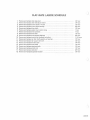
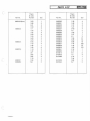
FLAT-RATE LABOR SCHEDULE
1.
2 ..
3.
4.
5.
6.
7.
8.
9.
10.
11.
12.
13.
14.
15.
16.
17.
18.
Remove
Remove
Remove
Remove
Remove
Remove
Remove
Remove
Remove
Remove
Remove
Remove
Remove
Remove
Remove
Remove
Remove
Remove
and
and
and
and
and
and
and
and
and
and
and
and
and
and
and
and
and
and
replace chain case cover ...... .. . ... .. . . . . . . . . . . . . . . . . . . . . .
replace chain and adjust tension . . . . . . . . ... . . . . . . . . . . . . . . . . . . .
replace driven clutch or V-belt .. ... .... .. ...... . . .... . . . .....
replace di-iven clutch bearings ...... ... . . . . . . . . . . . . .... .. . .. .
replace drive clutch ... ..... . . . . . . . . . . . . . . . . . . ...... .... ..
replace engine mount and/or strap . . . . . . . . . . . . . . . . . .... . . . . . . .
replace drive sprockets . . ... . . . . . . . . . . . . . ... . . . . . . . . . . . . .. .
replace drive shaft . . . . . . . . . . . . . . . . . . . . . . . . . . . . . . . . . . . . . . .
replace drive sprocket bearings . .. ... .. . . ...... . . ... ...... .. .
replace traction belt (endless) and adjust . . . . . . . . . . . . . . . . . . . . . . . .
replace rear idler shaft assembly or bearings . . . . . . . . . . . . . . . . . . . . ..
replace rear support arms (2) . . . . . . . . . . . . . . . . . . ..... . . ... ....
replace throttle cable ..... ... .... . . . . . . . . . . . . . . . ..... ... ..
replace brake cable . . .... .. . . . . . . . . . . . . . . . . . . . . . . . . . . . . . .
replace steering spindle .... .. . .. ..... ... . .... .. ..... .... ..
replace spindle arm . . . . . . . . . . . . . . ... . ... . . . . . . . . . . . . .. ...
replace carburetor . . . ... . . . . . . . . . . . . . . . . .. ... . .. ...... ...
replace Suspension System .. . . . . . . . . . . . . . .. ...... . . . . . . . . . .
.
.
.
.
.
.
.
.
.
.
.
.
.
.
.
.
.
.
1/4 hour
1/4 hour
1/2 hour
3/4 hour
1/2 hour
1 hour
1 hour
1/2 hour
3/4 hour
1-1/4 hours
1/2 hour
1/2 hour
1/4 hour
1/4 hour
1/2 hour
1/4 hour
3/4 hour
1/2 hour
1003632
CONTENTS
c
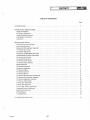
TABLE OF CONTENTS
Page
INTRODUCT ION
. . . . . .. . .
PREDELIVERY INSTRUCTIONS
Install Ski Assembly
Ski Damper Adjustment
Install Windshield Assembly
Fuel Mixture Instruction s
Lu brication . . . . .
c
1
2
2
2
3
SERVICE AND REPAIR
Hood Removal and Installation
Hood Assembly Repair .. . .
Steering and Ski Assembly Alignment
To Remove Drive Chain . . . . . . . .
Drive Chain Adjustment
. . . .. . .
To Remove Variable-Speed Drive Belt
Variable- Speed Drive Belt Adjustment
To Remove Drive Clutch
Drive Clutch Alignment .. .
To Remove Driven Clutch
To Remove Brake Assembly
Brake Adjustment . . . .
To Remove Carburetor .
Carburetor Adjustments
To Remove Engine .
To Remove Gas Tank ..
To Remove Muffler . ..
To Remove Sprocket Sea ls and Bearings
To Remove Drive Sprocket Assembly
To Remove Suspension Assembly
To Remove Traction Belt
Traction Belt Adju stment . . . .
Traction Belt Alignment
Traction Bell Tension Adju stment
Suspension System Adjustment
Spark Plug Replacement
Wiring Diagrams .
Troubleshooting
3
3
3
3
4
4
5
5
5
6
ILLUSTRATED PARTS LIST
14
6
6
6
7
7
8
9
9
9
9
10
10
10
10
11
11
11
12
12
c
1003632
ilii
)
INTRODUCTION
c
leSia~
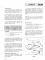
The windshield and ski assemplies will be found in the
shippi ng container. Carefully open the container and
immediately inspect the equ ipment for any damage or
missing items. The spindle pads and locknuts will be found
in the plastic bag. The bushings and screws are installed on
the spring mounting bracket to retain the ski-damper during
shipping.
INTRODUCTION
This manual has been prepared to provide all authorized
AMF Ski-Daddler Dealers, Distributors and technicians with
the instructions necessary to service and maintain the AMF
High-Performance Series XX Ski-Daddler snowmobiles.
The series classification for each snowmobile is clearly
shown on the left-hand side of the console control panel.
The Model Number and Serial Number are permanently
stamped on the nameplate attached to the rear right-hand
side of the main frame assembly . When ordering accessories
or replacement parts, always indicate the correct Model
Number and Serial Number as shown on the nameplate.
IMPORTANT: The owner must retain the Ski-Daddler
Inspection Record, Form No. 44770A. This form must be
shown to the dealer should any claim arise for missing or
damaged parts.
The following chart identifies the Ski-Daddler series
classification, corresponding model numbers and engine
designation covered in this manual.
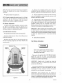
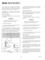
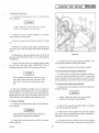
Install Ski Assembly
• Remove the screw (3, figure 1) and bushing securing
the ski-damper to the spring mounting bracket.
Series
Classification
Model Number
Engine
XX-1300
XX-1340
SD15M28B
SD15M26B
292
340
11T
• Place the spindle pad (1, figure 1) in the spring
mou nting bracket with the thicker section and the
directional arrow on the pad pointing forward.
• Secure the ski assembly to the lower end of the
spindle assembly by inserting the screw (3) and bushing
through the ski damper, spring mounting bracket and
spindle tube as illustrated. Apply 30 foot-pounds torque to
the locknut (2). Do not overtighten locknut as ski assembly
should float freely on the spindle.
SD15M28B
I
Eng;ne manufacturer's code number
Manu a l start
Traction belt width in inches
Sk i-Daddler
This manual is presented in two sections. The first
section, Maintenance, provides the instructions necessary
for maintenance and service while the second section, the
Illustrated Parts List is provided to facilitate the ordering
of spare and replacement parts.
The Parts List section also contains a numerical listing of
all items shown in the Illustrated Parts List. Thus, if the
part number is known but not its application, refer to the
numerical list. If the part number is not known, locate the
item on the illustration to obtain the index number keyed
to the applicable parts list_
If the information in this manual is not applicable to all
models, the exceptions will be noted and the correct
information for the particular model will be given.
c
SKI-DAMPER
ASSEMBLY--:_ _.l-..-/
ADJUSTING NUT
PREDELIVERY INSTRUCTIONS
The AM F Ski-Daddler snowmobiles are shipped
completely assembled except for the windshield assembly
and the ski assembly.
1003632
Figure 1
1
~NMlal PREDEL/VERY /NSTRUCT/ONSI~
)
NOTE: Be certain to install skiis with pivot of ski damper
forward and adjusting nut to outside of Ski-Daddler as
illustrated.
•
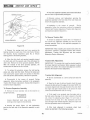
• Remove the protective plastic cover from the
windshield. Place the windshield in position on the hood
assembly . Replace the mounting strips as shown in figure 2.
• Using the original screws, loosely secure the mounting
strips and windshield to the hood assembly starting at the
center and working to the sides.
Repeat procedure for opposite ski.
NOTE: Properly installed skiis should toe out 0- to 1/2-inch
at the front end and should be symmetrical about the
center Iine of the sled. If necessary, refer to paragraph
Steering and Ski Assembly Alignment procedures.
• Engage the ends of the mounting strips over the trim
strip on the windshield and then tighten the screws, starting
at the sides and working to the center. Remove the
protective covering from the mounting strips. NOTE :
Check mounting strips for sharp edges or corners. Use a
fine-tooth file to smooth any sharp edges and corners.
Ski Damper Adjustment
To adjust the ski damper assemblies, remove the cotter
pin (figure 1) and tighten or loosen the adjusting nut as
required to achieve the desired tension. Replace cotter pin
and repeat procedure on opposite ski assembly .
IM PORTANT: Before replacing the hood assembly, check
the steering column to insure that it is not too loose nor
too tight. Adjust the bolts securing the steering colu mn and
U-straps at the roll bar and tachometer bracket as required
to obtain the desired feel and to insure good steering
response.
Install Windshield Assembly
•
Disconnect hood harness at the quick disconnect .
• Remove hood assembly. Refer to Hood Removal and
Installation procedure.
•
• Remove the screws (figure 2) securing the right- and
left-hand mounting strips to the hood . Remove the
mounting strips.
Replace the hood assem bly.
Fuel Mixture Instructions
WARNING'
WINDSHIELD TRIM
MOUNTING
STRIP, LH
Never fill the gasoline tank while the engine is
hot. Wipe off any spi lled gaso line before
attempting to start engine.
The correct oil -to-gasoline ratio is 20: 1 (20 parts regul ar
gasoline to 1 part oil) . Too much oil will cause carbon
deposits. Too little oil or a poor mix will cause insufficient
lubrication and possible engine damage.
IMPORTANT: Gasoline and oil should be mixed at
temperatures above zero. At temperatures below zero gas
and oil mix with difficulty.
Fuels containing additives are not recommended for use in
Ski-Daddler engines. For mixing with gasoline, use AMF
Nondetergent oil, Citgo, Rislone or Kendall oil prepared
exclusively for use in air-cooled, 2-cycle engines.
IMPORTANT: Some outboard motor oils contain an
additive that works well in outboard motors that operate at
much lower temperatures because they are water cooled.
However, the additives may cause spark plug fouling in the
air-cooled engines used on Ski-Daddler snowmobiles.
Figure 2
2
1003632
~ SERVICE AND REPAllOeMI3~
c
No . 2 lithium bearing grease may also be applied as
required to the wearplates and U-straps securing the
steering column tachometer bracket to the roll bar.
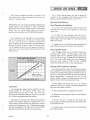
Use a mixture of gasoline and AMF oil as shown in the
Fuel Mixture Chart. Never use gasoline left over from the
summer or previous winter.
SERVICE AND REPAIR
IMPORTANT: the new no-lead anti-pollution gasolines may
contain additives that contribute to higher combustion
temperatures and varnish formations that may cause engine
seizing. Use only normal leaded regular and premium
gasolines when mixing for use in the Ski-Daddler engines.
Hood Removal and Installation
• To remove the hood assembly, release the hood latch
assemblies and remove the hood assembly by lifting rear
portion first .
• To install the hood assembly, place the hood in
position on the sled so that the forward hood clip and the
bottom edge of the hood engages the clips along the inside
edge of the bumper.
Mix the gasoline and oil thoroughly in a clean container
kept for this purpose only. The best way to ensure a good
mix is to pour the oil into a container with about one
gallon of gasoline and mix thoroughly. Then add additional
amounts of gasoline as shown on the Fuel Mixture Chart.
Fill Ski-Daddler gas tank from this separate container of
mixed fuel. Use a funnel with a fine-screen strainer when
filling the tank.
• Engage the left- and right-hand latch assemblies and
insert safety pins to secu re the hood to the main frame .
Hood Assembly Repair
AMF Fiberglass Repair Kits are available through your
authorized AM F Dealer. For large repairs, order AM F
Fiberglass Repai r Kit No . 1510693. Smaller repairs can be
made with Repair Kit No. 1510765 . Paint all repaired areas
on the hood using AM F-Orange color paint available in
easy-to-use spray container, AMF Part No. 1510828.
Follow the instructions in the kit when making repairs .
FUEL MIXTURE CHART
OIL (Ounces)
o
4
8
12
16
20
24
28
32
36
40
5 ~--r--+--~--+--+--~--+-~~~~
4~--t--1---+---r--+---~~~
__~+-~
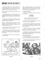
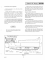
Steering and Ski Assembly Alignment
Good steering ability requires that the skis be properly
set and aligned with the sled body when the steering handle
is placed in the straight-ahead position. Remove any play in
the skis by pulling the skis toward the center of sled before
taking measurements. To determine that the skis are
properly aligned, measure the distance between the inside
edges of the skis at the front end and at the rear.
GASOLINE
(Gallons)
GASOLINE/OIL RATIO - 20 to 1
Properly aligned skis shou ld toe out 0- to 112-inch
maximum at the front. If the skis or steering mechanism are
not properly set, adjust as follows:
Lubrication
A low-temperature grease must be applied to the zerk
fittings located on the steeri ng spindle tubes; after
approximately each 20 hours of use. The chain case
housing must be checked after each 10 hours of use and
No.2 lithium bearing grease added as required .
c
•
• Remove the hood assembly. Refer to Hood Removal
and Installation.
The bearing cup retai ners that hold the drive and idler
sprocket seal bearings should be repacked with No. 2
lithium bearing grease whenever the bearings are removed
during normal maintenance. No . 2 lithium bearing grease
may also be applied to the inside of the drive and idler
sprocket bearing retainers during normal maintenance.
1003632
Place steering handle in a straight-ahead position.
• Remove the bolt (1, figure 3 ), two spacers (2),
bottom spacer and locknut securing the rod end bearing (3)
to the spindle arm (6) .
• Loosen the jam nut (4) securing the rod end bearing
(3) to the tie rod (5).
3
SERVICE AND REPAIR
• Move the affected ski into proper alignment and
recheck measuring points to insure that the skis toe out 0to 1/2-inch maximum at the front end and are in the same
orientation with the sled body as shown in figure 2_
NOTE: Sk i-damper adjustment is not normally requ ired
during ski-a lignment procedures. However, if adjustment is
desired, tighten or loosen the ad justing nut shown in figure
1 as required to obtain the desired t ension.
NOTE: If both skis need adjustment, repeat procedure for
the opposite sk i.
To Remove Drive Chain
)
• Remove the hood assembly. Refer to Hood Removal
and Installation .
• With skis properly set and steering handle in the
straight-ahead position, rotate rod end bearing (3, figure 3)
as required to bring rod end bearing in line with the spindle
arm (6) .
Always disconnect spark plug wires before
working on the engine or drive elements.
• Secure rod end bearing (3) to spindle arm (6) as
illustrated. Check for proper alignment and then tighten
jam nut (4) to secure rod end bearing.
• Remove the locknut securing the chain cover top and
remove chain cover top and spacer sleeve.
NOTE: If a greater adjustment is required than that
permitted by the steering linkage assembly, it will be
necessary to align the ski by making the adjustment at the
spindle tube assembly as follows:
• Loosen the bolts (1, figure 4) on both cam uprights
(2) and rotate the cam and shaft (3) as requ ired to loosen
the chain tension . During reassembly, apply 30 foot-pounds
torque to the bolt (1) .
• Remove screw (5, figure 4) and locknut (6) securing
spindle tube assembly (7) to spindle arm (8).
• Remove the cotter pin, slotted nut and washer
securing the top sprocket to the driven clutch shaft.
Remove the top sprocket and chain together.
• Remove spindle arm (8) and rotate ski and spindle
one notch in the requ ired direction; replace and secure
spindle arm to the spindle. Apply 20 foot-p6unds torque to
the locknut (6) .
)
• Reassembly is the reverse of removal. Perform drive
chain adjustment procedures and add No.2 lithium bearing
grease as required to the chain case.
• Recheck the skis for proper toe out and alignment as
previously described .
Drive Chain Adjustment
A properly adjusted drive chain (figure 4) should have a
1/8- to l/4-inch slack. Check and adjust chain as follows:
• Remove the locknut securi ng the chain cover top and
remove chain cover top and spacer sleeve.
)
Figure 3
Figure 4
4
1003632
SERVICE AND REPAIR
c
• Rotate the upper sprocket to tension one side of the
chain and then check the opposite side for proper slack. If
adjustment is req uired, loosen the bolts (1) securing the
cam uprights (2) on each side. During reassembly, apply 30
foot-pou nds torque to the bolts (1).
Variable-Speed Drive Belt Adjustment
• Rotate the cam (3) counterclockwise to tighten or
until the chain is properly tensioned. Hold the cam in this
position while tightening the cam upright bolts (1) on each
side. Be certain the lateral alignment between the drive
clutch and the driven clutch (4) is maintained while the
cam upright bolts are tightened.
Measurement must be taken as close to the drive clutch
flanges as possible. Be certain the driven clutch does not
open when belt is squeezed .
Proper drive belt tension is obtained when opposite sides
of the belt can be squeezed between the drive clutches to
2-3/4 to 3-1/4 inches as measured between the top and
bottom outside surface of the belt.
IMPORTANT: Do not use antislip belt dressing. Belt
slippage is a safety feature which prevents overstressing
drive-system components.
• Recheck chain tension before replacing the chain
cover, top and spacer sleeve.
• To adjust drive belt tension, loosen the locknut (8,
figure 3) securing the clutch rod tensioner to the main
frame assembly .
To Remove Variable-Speed Drive Belt
• Remove the drive chain . Refer to pa ragraph To
Remove Drive Chain.
•
c
USIA
NOTE: If the drive belt is wearing unevenly, check
alignment as described in Drive Clutch Alignment
procedures.
Remove the clutch guard assembly.
• Loosen the locknut (8, figure 3) and serrated washer
(7). During reassembly, apply 10 foot-pound s torque to the
locknut (8).
• Move the driven clutch (9) in the direction required
to obtain proper belt tension. Hold this position while
tightening the locknut to secure the clutch rod tensioner.
Be certain the washer (7) and bar serrations are properly
engaged. Apply 10 foot-pounds torque to the locknut (8) .
• Push the driven clutch toward the drive clutch to
permit removal of the variable-speed drive belt from the
drive clutch. If necessary the drive belt can be removed
from the drive clutch after the driven clutch is removed
from the bearing clamps.
To Remove Drive Clutch
• Remove the hood assembly . Refer to Hood Removal
and Installation.
• Remove the locknuts (7, figure 6) securing the
bearing clamps (8) and remove the bearing clamps. During
reassembly, apply 5 foot-pounds torque to the locknuts (7).
Always disconnect spark plug wires before
working on the engine or drive elements.
• Lift the driven clutch and drive belt clear of the brake
assembly and remove the variable-speed drive belt.
•
• Install replacement drive belt. Use AMF Part No.
37880 on Models SD15M26B and SD15M28B ;
• Loosen the locknut (8, figure 3) and serrated washer
(7) secu ring the clutch rod tensioner to the main frame .
During reassembly, apply 10 foot-pounds torque to the
locknut (8).
NOTE: Variable-speed drive belt installation procedures are
the reverse of removal except that the belt must first be
placed around the driven clutch and then around the drive
clutch. After installation, perform the drive chain
adjustment, variable-speed belt adjustment and the drive
clutch alignment procedures.
• Push the driven clutch toward the drive clutch to
permit removal of the variable-speed drive belt from the
drive clutch . If necessary remove belt after drive clutch is
removed from engine.
c
1003632
Remove the clutch guard assembly.
5
~t!MI31 SERVICE AND REPAIR I~
• Tighten engine holddown nuts and recheck
• To remove the drive clutch, remove the clutch
adapter bolt and washer. If necessary, use a clutch puller
and remove the drive clutch. NOTE: During reassembly
apply 50 to 60 foot·pounds torque to the clutch bolt.
alignment. Apply 25 foot-pounds torque when tightening
the engine holddown nuts.
To Remove Driven Clutch
• Reassembly is the reverse of removal. Perform
variable-speed drive, belt adjustment and drive clutch
alignment procedures.
NOTE .: The procedures required to remove the driven
clutch are the same as those described in paragraph To
Remove Variable-Speed Drive Belt.
Drive Clutch Alignment
To Remove Brake Assembly
• Remove the hood assembly. Refer to Hood Removal
and Installation .
• Remove hood assembly. Refer to Hood Removal and
Installation.
Always disconnect spark plug wires before
working on the engine or drive elements.
•
Always disconnect the spark plug wires before
working on the engine or drive elements.
Remove the clutch guard.
• Loosen the engine holddown nuts (figure 5) securing
the engine supports to engine mount straps.
• Disconnect brake cable and housing (3, figure 6) at
brake mounting bracket and at brake actuating lever.
• Place a straightedge on the fixed face of the drive
clutch and move the engine until the offset between the
stra ightedge and the front and rear edges of the driven
clutch is set to the A dimension as shown in figure 5.
Rotate driven clutch 90- degrees and repeat procedure.
• Remove the bolts and lockwashers securing the
mounting bracket to the driven clutch mounting.
A
B
Remove the brake assembly .
• Installation procedures are the reverse of removal.
Refer to Brake Adjustment procedures.
(TORQUE)
FT·LB
MODEL NO.
ENGINE
CLUTCH
0.20
55 ± 5
SD15M28B
292
700 Series
0.20
55 ± 5
SD15M26B
340
700 Series
-J I_ ®
•
Brake Adjustment
• To adjust the brake pads (5, figure 6) to the disk (1),
remove the cotter pin (2) and tighten or loosen the castle
nut (4) as required to permit the brake pads (5) to just clear
the brake disk. Reinstall the cotter pin.
~
• To adjust for excessive play in brake cable or lever
position, loosen jam nuts (6) and move brake housing (3) as
required. Tighten jam nuts.
STRAIGHTEDGE
DRIVEN CLUTCH
Check brake action after each adjustment to insure
proper brake operation. If necessary apply loctite antiseize
lubricant to the actuating cam lever (9, figure 6) and the
steel pins (10) as follows:
• Remove the cotter pin (2) and the castle nut (4) .
Remove the actuating cam lever (9) and apply lubricant to
the cam lever surface that contacts the pins (10) . Remove
the pins and apply lubricant to the pins. Reassemble the
cam lever and pins.
DRIVE CLUTCH
HOLD DOWN NUTS
VIEW
0
Figure 5
6
1003632
SERVICE AND REPAIR
c
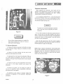
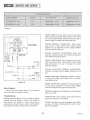
Carbu retor Adjustments
When adjusting the carburetor, best results will be
obtained if the adjustments are made on a warm engine.
During carburetor adjustments, DO NOT FORCE
ADJUSTMENT SCREWS INTO SEATS .
• TO ADJUST CARBURETOR - Close the high-speed
jet (DO NOT FORCE) . Then open the high-speed jet (figure
7) to the settings shown on the carburetor settings chart for
the particular engine (see figure 8) .
The engine can be seriously damaged if operated
with a lean gas mixture (high-speed jet turned
in too far).
Figure 6
WARNING
c
• Turn the low-speed jet (idle-mixture screw) shown in
figure 7 all the way in (DO NOT FORCE), then open as
shown in figure 8 for the particular engine. This ad justment
controls the mixture at idling speeds. A lean idle mixture
will result in poor acceleration.
I
Do not allow antiseize lubricant to contact the
brake pads (5, figure 6) or disk (1) . To do so
will result in brake slippage.
Keep the idle speed slower than the clutch engaging
speed by adjusting the idle-speed screw. NOTE: Do not use
the low-speed jet to adjust for idle speed.
To Remove Carburetor
• Remove the locknut securing the throttle rod screw
to the carburetor linkage. Remove the throttle rod screw
and jam nuts.
NOTE : Figure 7 shows a throttle-wire. If the throttle plate
fail s to open completely when the throttle contro l lever is
depressed, loosen the throttle-wire adjustment screw and
readjust the wire as required to ensure that the throttle
opens fully and returns freely.
• Remove the screws securing the ram tube to the
carburetor and remove the ram tube.
• Disconnect the fuel lines at the carburetor. Wipe up
any spilled gasoline immediately. Be certain to note the
position of the gas line and impulse lines to insure proper
reassembly.
• Remove the jam nuts and lockwashers securing the
carbu retor to the intake manifold and remove the
carburetor.
• Remove the gasket. Do not damage the gasket if
required for reassembly . NOTE: Replacement carburetors
are supplied with a new gasket.
c
• Installation is the reverse of removal. Adjust the
carburetor as described in the Carburetor Adjustment
procedures.
1003632
Figure 7
7
SERVICE AND REPAIR
)
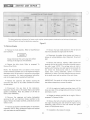
CARBURETOR SETTINGS CHART
SERIE S
CLASSIFICAT ION
ENGINE
SD15M28B
XX-1300
292
1
SD15M26B
XX-134O
340
1
MODEL NO.
HIGH-SPEED JET
+ 1/8
-
-
Open
1- 1/8
Open
1-1/8
0
+ 1/8
0
LOW-SPEED JET
+ 1/8
-
0
+ 1/8
-
Open
Open
0
The above carburetor settings are for factory stock engines, exhaust systems, carburetion and various altitudes may
require different settings for satisfactory operation.
Figure 8
To Remove Engine
• Remove the heat shield attached to the roll bar and
main frame between the engine and the muffler.
• Remove the hood assembly . Refer to Hood Removal
and Installation .
• Disconnect the engine wiring harness and loosen or
remove all wiring holddown clips. Di sco nnect the ground
lead.
Always disconnect the spark plug wires before
working on the engine or drive elements.
• Remove the locknuts, washers, rubber spacers and
bushings securing the engine and engine mounting straps to
the main frame. NOTE: The carriage bolts are held in
position with Tinnerman nuts and need not be removed. Do
not remove the shock mounts unless it is necessary to
replace them. During reassembly, tighten t he locknuts
sufficiently to allow a 5/16-inch clearance between bottom
of the shock mount and top surface of the main frame.
• Remove the drive clutch. Refer to paragraph To
Remove Drive Clutch.
NOTE: The Illustrated Parts list section of this manual
contains detailed exploded views of the engine and support
assemblies which will be helpful if referred to during engine
removal procedures. For engine maintenance instruction,
refer to the engine manual supplied with each sled.
• Remove the cap screws and washers securing the
carburetor heat shield to the intake manifold and remove
the heat shield.
IMPORTANT: Be certain all wiring and gasoline lines are
clear before attempting to remove the engine.
• Disconn ec t the gas lines at the carburetors.
Disconnect impulse lines at the engine. Wipe up any spilled
gasoline immediately. Note the position of all lines to
insure proper reassem bly.
• lift the engine and engine mounting straps until the
straps are clear of the carriage bolts and remove the engine
and straps as a unit.
• .Release the exhaust manifold at the engine. Refer to
paragraph To Remove Muffler.
• Remove the capscrews and spring lockwashers
secu ring the left· and right-hand intake manifold to the
engine. Remove the intake manifolds, carburetors and ram
tubes as a unit.
• Remove the bolt and washers securing the engine to
the engine mounting plate and remove the engine. During
reassembly, apply loc-tite to the bolt threads and tighten
bolts to 18 foot-pounds torque.
• Remove the engine-to-manifold gasket if required for
reassembly. NOTE: New, replacement engines are suppl ied
with new engine-to·manifold gaskets.
•
8
Installation is the reverse of removal.
1003632
)
SERVICE
C
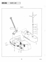
To Remove Gas Tank
• Remove the hood assembly. Refer to Hood Removal
and Installation.
Always disconnect spark plug wires before
working on the engine or drive elements.
• Check gas cap and indicator assembly to be certain
tank is empty. or nearly empty.
•
Remove the gas cap and indicator assembly (1 . figure
9).
• Remove the bolts (3) and washers securing the gas
spill chute (2) to the main frame and remove the gas spill
chute.
Figure 9
• Disconnect the tank-to-carburetor gas lines (6) at the
gas tank outlet fitting (5). Wipe up any spilled gasoline
immediately.
• Loosen the bolt and nut securing the muffler to the
mounting band assembly. Remove the muffler.
•
Remove the gas tank (4) by carefully sliding the tank
up and away from main frame. IMPORTANT: Do not
damage the gas tank outlet (5) when removing the tank.
•
Installation procedures are the reverse of removal.
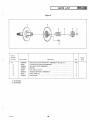
To Remove Sprocket Seals and Bearings
• Sprocket seals and bearings are located on each end
of the drive sprocket assembly drive shaft. To replace the
seals or bearings it will be necessary to remove the drive
sprocket assembly as described in the following paragraph.
Do not attempt to make any repairs to the gas
tank. Use extreme care when removing the gas
tank. Do not remove tank near flame or open
fire .
To Remove Drive Sprocket Assembly
• Remove the hood assembly and set the machine on
its right-hand side.
• Gas tank installation procedures are the reverse of
removal. NOTE: If the original tank is not to be installed. it
will be necessary to remove the gas tank outlet (5) and the
attached gas line filter; also the pressure relief valve (7).
These items are to be installed on the replacement tank.
Always disconnect spark plug wires before
working on the engine or drive elements.
To Remove Muffler
• Remove the hood assembly . Refer to Hood Removal
and Installation.
c
• Remove the suspension assembly. Refer to paragraph
To Remove Suspension Assembly .
Always disconnect the spark plug wires before
working on the engine or drive elements.
• Remove the lower sprocket from the drive sprocket
shaft and remove the sprocket and chain as described in
paragraph To Remove Drive Chain.
• Loosen the clamp securing the muffler to the dualexhaust manifold.
• Using a screw driver. carefully pry the oil sea ls (figure
10) away from the bearings at each end of the drive shaft.
1003632
9
SERVICE AND REPAIR
• Pivot the suspension assembly and traction belt about
the front axle to approximately gO-degrees.
)
• Remove screws and lockwashers securing the
suspension assembly to the front end of the main frame and
remove the suspension assembly.
• Installation is the reverse of removal.
During
reassembly, follow the instructions outlined in paragraphs
Traction Belt Tension Adjustment, Traction Belt Alignment
and Suspension System Adjust ment.
To Remove Traction Belt
To remove or replace the traction belt it is necessary to
first remove the suspension assembly and then the drive
sprocket assembly. Refer to the applicable paragraphs for
removal procedures.
DRIVING SPROCKETS
Figure 10
IMPORTANT: When installing the traction belt, follow the
instructions outlined in paragraphs Traction Belt Tension
Adjustment, Traction Belt Alignment and also recheck
Suspension System Adjustment.
• Remove the carriage bolts and nuts securing the
bearing retainers to each side of the main frame. Remove
the retainers. During reassembly apply No. 2 lithium
bearing grease to the bearing retainers.
• Move the drive shaft and sprocket assembly toward
the chain side until the opposite end of the shaft clears the
other side. Remove the drive sprocket assembly. NOTE:
With the removal of the drive sprocket assembly, the
traction belt will also be free for removal.
Traction Belt Adjustment
IMPORTANT: The traction belt must be checked regularly
for proper alignment and tension. When necessary to adjust
the belt, first perform the traction belt alignment and then
complete the traction tension adjustment .
• To replace the sprockets, remove the ball bearing,
grease seal, col lar and idler wheel. Remove the screws and
nuts securing the support plate and sprocket to the drive
shaft and sprocket plate assembly. Remove the sprocket.
Traction Belt Alignment
• Set the snowmobile on a level surface and raise the
back end.
• Reass e mbly is the reverse of removal. During
reassembly follow instructions outlined in the paragraphs
Traction Belt Tension Adjustment, Traction Belt Alignment
and Drive Chain Adjustment.
• Stand to the rear of sled and visually check the space
between the slide rail and the edges of the track. NOTE: On
a properly aligned track this space should be the same. Start
the engine and again visually check to be certain the track
remains centered whi le the track is running.
To Remove Suspension Assembly
• Remove the hood assembly and set the machine on
its right-hand side.
• If the track is not centered, stop the engine and on
that side where the edge of the track is closest to the slide
rail, rotate the adjusting screw (figure 11) until track is
centered. Pull the track for a few revolutions and then
start the engine and recheck alignment. Stop the engine and
lock the adjustment screw in this position.
Always disconnect spark plug wires before
working on the engine or drive elements.
• Remove the screws (figure 11) and lockwashers
securing the back end of the suspension assembly to main
frame.
• After track alignment is complete, check track
tension as described in the following paragraph.
10
1003632
)
~ SERVICE AND REPAIR leSl3~
c
• Raise the back end of the snowmobile until the track
clears the ground. Start the engine and allow the track to
rotate several turns. Then, stop the engine and repeat the
track tension adjustment procedure to ensure that proper
tension is maintained.
Traction Belt Tension Adjustment
• Set the snowmobile on a clean, flat surface and raise
the back end of the sled .
• Check traction belt tension by firmly pulling the
track downward at the center of the track . A properly
tensioned track should have a 1- to 1-1/2-inch clearance
between the plastic runner and the track cleats at the
approximate bottom center of the track . NOTE: Do not
attempt this with the engine running. Traction belt cleats
are sharp and must be handled carefully .
Suspension System Adjustment
The suspension system may be adjusted for a soft or
firm ride, or for varying snow conditions. If a firmer ride is
desired, adjust the jamnuts (figure 11) to tighten the
eyebolts located on each side of the track. Loosen the
eyebolts if a softer ride is desired. Adjust front or rear sets
of eyebolts equally.
• If adjustment is necessary, loosen the locknuts (figure
11) on each side of the sled and rotate the adjusting screws
as required to obtain proper track tension. IMPORTANT:
Adjust both screws equally so as not to disturb the track
alignment. Retighten the locknuts on both sides of the
snowmobile.,
Spark Plug Replacement
To maintain top engine performance the condition of
the spark plugs should be checked periodically and the gap
reset to 0.020-inch using a wire gauge. During reassembly
apply 18 to 20 foot-pounds torque.
Spark plug condition may be determined by the color. A
carbonized plug is black; a burnt plug is pale gray, whereas
a normal functioning spark plug is brown.
c
When replacing spark plugs, use AMF-approved spark
plugs to insure proper spark plug heat ranges for a
particular engine. NOTE: The Spark Plug Chart is provided
to identify spark plugs for light or severe service.
Never run the engine inside a building without
first opening all doors and windows to insure
proper ventilation.
h~=;:='r
L -:':;;:;:;:==l\
1
JAMNUTS
'C
PROPER TENSION
l -TO l1f.z -INCH PULL
Figure 11
1003632
11
~eMial SERVICE AND REPAIR
III
)
SPARK PLUG CHART
MODEL NUMBER
ENGINE
LIGHT SE RVICE
SEVERE SERVICE
SD15M28B (XX-1300)
292
38058 (N60 or *41XL)
38068 (N57 or 41XC)
SD15M26B (XX-1340)
340
38058 (N60 or *41XL)
38068 (N57 or 41 XC)
*Optional
ENGI NE STOPS. Fuel tank empty; fuel flow obstructed;
ignition system faulty. Spark plug(s) fouled or dirty. Engine
too hot and pistons seizing; carburetor setting too lean or
incorrect grade of oil being used, impulse line loose.
ENGINE OPERATES IRREGULARLY. Spark plug(s)
loose, fouled or faulty; ignition switch wiring shorted;
carburetor out of adjustment or dirty. Engine holddown
bolts loose; ignition timing off.
HIRTH 292 ENGINE
HIRTH 340 ENGINE
I
I
- - - -~-=-~-~-~-~-~-~-~-~~~E~N~GI~N~E·WIR~~
---- ~ ----------
o
'"
....l
....l
U
<{
>
II>
W
ENGINE WORKING FOUR -STROKE. Choke shut;
carburetor settings incorrect; dirt preventing carburetor
inlet needles from seating properly .
CONNECTIONS
...J
ENGINE LOSES POWER. Poor compression due to loose
head and crankcase bolts. Faulty ignition; timing; piston
rings sticking due to the use of improper oil. Carbon
deposits in cylinder.
TACHOMETER
BLACK
BLACK
RED
, ,
I
I
I
RED
,
I
,
I
,
I
BLUE
:
ENGINE BACKFIRES THROUGH CARBURETORS.
Carburetor fuel -supply channel clogged. Carburetor set too
lean.
QUICK-KILL
SWITCH
BLACK
BLACK
;~r:
ENGINE BACKFIRES THROUGH EXHAUST. Incorrect
or faulty spark plug(s); faulty ignition coil or condenser;
loose ignition wiring.
_
Figure 12
ENGINE OVERHEATS. Insufficient or incorrect grade oil
in fuel mixture; carburetor or fuel line partly clogged;
carburetor setting too lean; ignition timing too slow.
Wiring Diagrams
The electrical wiring diagram (figure 12) is provided for
the trained technicians using th is manual.
BRAKES. Excessive play in handbrake due to loose brake
cable or worn pads.
Troubleshooting
TRACTION BELT. Poor traction; check traction belt for
ENGINE HARD TO START. Fuel line blocked or leaking;
ruptured fuel-pump diaphram; water in fuel, flooded or
loose impulse line; ignition or switch wiring loose or
grounded; spark plug(s) fouled or faulty; contact breaker
points pitted or burned; quick-kill switch in off position.
alignment and tension; worn sprockets.
CLUTCH. Automatic clutch fails to engage at proper RPM's.
(see figure 13) . Check variable-speed drive belt for proper
tension and alignment.
12
1003632
~I SERVICE AND REPAIR leSla~
c
SKI ASSEMBLY . Poor steering ability due to loose skis;
worn wear rod. Poor riding characteristics due to loose or
defective ski-dampers.
CLUTCH ENGAGEMENT SPEEDS
ENGINE
ENGINE RPM
XX-1300
292
4300± 300
XX -1 340
340
4300 ± 300
CLASS
STEERING. Poor steering ability caused by improperly
adjusted skis; steering linkage loose or out of adjustment.
U-bracket bolts on roll bar too tight or too loose. Spring,
U-bracket loose.
Figure 13
EXCESS IVE FUEL CONSUMPTION. Carburetor fuel line
or gas tank leaking; choke closed; incorrect carburetor
setting.
THROTTLE CONTROL Excessive play in throttle control
lever caused by loose throttle control cable.
r
c
1003632
13
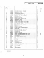
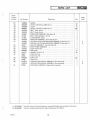
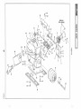
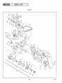
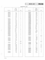
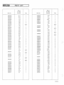
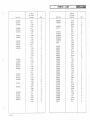
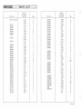
PARTS LIST
ILLUSTRATED PARTS LIST
Where no code letter appears in the code column, the
part is used on all models to which the particular figure
applies.
This section of the dealer's manual consists of an
illustrated parts list and a numerical index.
All model codes will be listed at the bottom of each
parts list page to provide a ready reference.
PARTS LIST
Th e parts-list consists essentially of exploded-view
illustrations keyed to the figure-reference column by index
numbers. The Parts List is arranged in the following
columns:
NUMERICAL INDEX
Th e numerical index is provided to afford dealers and
distributors with a means of determining to which models
their stock applies. The index consists of the following
three columns:
Figure-and-Index Number. The number preceding the dash
refers to the figure number on which the item is shown.
The number following the dash is the ind ex number keyed
to the item shown on the exploded view.
Part-Number Column. The part-number column tabulates
all parts called out in the parts list. The part numbers are
listed in numerical order starting with the first digit in the
number.
Part Number. The part number column identifies the item
by its assigned part number.
Index-Number Column. The index-number column reflects
the figure-and-index number of the part within the Parts
List. The number preceding the dash refers to the figure
number on which the item is shown. The number following
the dash locates the item within the given figure.
Description. The description co lumn identifies the part
with descriptive nomenclature.
Quantity . This column provides the total nu mber of items
required per assembly .
Quantity Co lumn . The quantity column reflects the total
number of parts required for the particular
figure-and-index-number application. In certain cases,
quantities differ between sled models. This circumstance is
covered by providing the larger quantity for the particular
figure -and-index number. In referring to the given
figure-and-index number in the parts-list section, the proper
quantity per sled may be determined.
Model Code. This column identifies, by code letter, the
Ski-Dadd ler models for which the part applies. The
following lists the code-to-model relationship:
Model
Code
SD15M28B
SD15M26B
A
B
Addendum . Numbers added.
14
1003632
)
PSl3
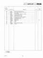
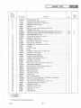
PARTS LIST
c
Figure
& Index
Number
1-
-1
-2
-3
-4
-5
-6
-7
-8
-9
-10
-11
-12
-13
-14
-15
-16
c
-17
-18
-19
-20
-21
-22
-23
-24
-25
-26
-27
-28
-29
-30
-31
-32
-33
-34
-35
-36
-37
-38
-39
-40
c
Part Number
1003106
1003107
1003525
1003280
1003461
1003462
9415426
33808
9000123
181648
120394
9000125
1003605
1003606
1003270
1003502
436752
1003366
9000122
1003353
10033 16
1002471
181577
181566
147579
9000123
1003291
1003290
33768
9000324
32532
32528
33769
37595
9000125
1003577
37345
9000302
120392
9000123
1003289
2791
1003371
Description
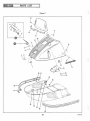
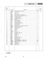
SKI -DADDLER, Model No_ SD15M28B _ _ . . .. . . .......... . . .
SKI-DADDLER, Model No . SD15M26B ... ..... . . . . . ....... .
WINDSHIELD, 15-lnch . . . .. .. ... . . . .... . ....... ..... _ .
HOOD ASSEMBLY (See figure 2) . . ... . . . . . ... . .. ........ .
BUMPER ASSEMBLY, RH (See figure 2) _ .. . . ..... . .. ...... .
BUMPER ASSEMBLY, LH (See figure 2) .... .. . . . . . . . . . . . . . .
SCREW, Truss HD, 1/4-28 by 1-1/2 IN. LG . . . . . . . . . . . . . ... . . .
WASHER, Formed ....... .. .. .. . .. .......... ... ... . . .
LOCKNUT, 1/4-28 THD .... . ... ... . .. . .... . ...... . . . . .
SCREW, HEX HD, 3/8-24 by 2 IN . LG ... . ... .......... .... .
WASHER, Plain, 13/32 ID . . . . . . . . . . . . . . . . _ . ...... ... .. .
LOCKNUT, 3/8-24 THD . . . . . . . . . . . . . . . ........ _ .. . . . . .
SKI AND SPRING ASSEMBLY, RH (See figure 3) . . . . . .... ... . .
SKI AND SPRING ASSEMBLY, LH (See figure 3) ..... ...... . . .
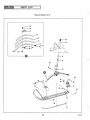
SEAT ASSEMBLY (See figure 4) ... . . . . . . . . . . . . . . . . . . . . . .
MUD FLAP, 15-lnch ............ .. ...... . .. ...... . ... .
SCREW, PAN HD, 10-32 by 3/4 IN . LG ....... _ ..... ... . ... .
STRAP, 15-lnch .. . ... ............. .. . .. ... .. ... .... .
LOCKNUT, 10-32 THD . ....... . _ .. ..... . . . . . . . .. .... . .
CLUTCH GUARD AND DECAL ASSEMBLY . . . . . . . . . . . . . . . . .
DECAL, Safety . . . . .. .. . _ . ..... .... .. .......... . ... .
STRAP, Clutch guard ........... . ... . . . ... . . . ... .. ... .
BOLT, HEX HD, 1/4-28 by 1-3/4 IN . LG ..... .. . . .... . . .. .. .
, BOLT, HEX HD, 1/4-28 by 3/4 IN. LG . ....... .. .......... .
WASHER, 1/4 ID . . ... . .. .......... _ ..... . .. . ... . ... .
LOCKNUT, 1/4-28 THD . . ..... . ... . . _ ..... . . ......... .
ENGINE AND SUPPORT ASSEMBLY (See figure 5) ...... .. . .. .
ENGINE AND SUPPORT ASSEMBLY (See figure 5) . . . . . . .. . .. .
SHOCK MOUNT .. . .. . ... . .. ... .... . .... ... . . ... .. . .
BOLT, Carriage, 3/8-24 by 2-1/4 IN. LG .. ... . ...... . ..... .. .
NUT ....... . .... _ ... . . . . . . . . . . . . . . . . . . . . . . ..... .
BUSHING . . . . . . . . . . . . . . . .. ....... . . ....... ... .. .. .
SPACER, Rubber .. ... . ........ . ... . ... ... ... .. . . _ . . .
WASHER ..... . .... . .... ... . . . .. .. . .. . ...... .. . .. .
LOCKNUT, 3/8-24 THD ......... .. . . .... ... .. . .. . .. . . .
HEAT SHIELD
.... .. ........' . . . . . . . . . . . . . . . . . . . . . .
SUPPORT, Heat shield ..... . .. . . . . . ... .. .. ... ..... .. . .
SCREW, Truss HD, 1/4-28 by 5/8 IN . LG . . .. . . . .......... .. .
WASHER, Plain, 1/4 ID . . .. ... . . . . . ....... . . . . . ....... .
LOCKNUT, 1/4-28 THD . . . . . . . . . . . . . . . . . . .......... . . .
SLED HARNESS .... .. . . . . . .. ........ . .... ...... . .. .
CLiP .... .. ... .. ..... ........ ..... ... . . . . . ...... .
TRACK ASSEMBLY ....... .. ........... ... ... . . .. . . .
A - SD15M28B
B - SD15M26B
1003632
15
Oty
1
1
Model
Code
A
B
1
1
1
1
4
4
4
2
4
2
1
1
1
1
4
1
4
1
1
1
2
1
4
3
1
1
4
4
4
4
4
4
4
1
2
4
4
4
1
1
1
A
B
45
21
23
24
....
en
14
."
<E'
c
n1
....
58
7
12
....
o
51
9
10
o
W
0>
W
I\)
u
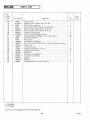
PARTS LIST
C
Figure
& Index
Number
1-41
-42
-43
-44
-45
-46
-47
-48
-49
-50
-51
-52
-53
-54
-55
-56
-57
-58
-59
-60
l
c
-61
Part Number
Description
Oty
1002803
9000828
1002808
9000827
1003434
1003433
1003597
181637
131099
1003730
1003491
1003492
37683
1003272
1002642
9000823
446143
30697
30696
9000829
37389
*1003274
1003275
*37926
GUIDE. . . . . . . . . . . . . . . . . . . . . . . . . . . . . . . . . . . . . . . . . . .
RIVET, 3/16 DIA by 0.652 IN. LG . . . . . . . . . . . . . . . . . . . . . . . .
CLEAT .. .. . .... . ..... . . . . . . . . . . . . . . . . .. . .... ....
RIVET, 3/16 DIA by 0.527 IN. LG . . . . . . . . . . . . . . . . . . . . . . ..
BELT, Track, 3-lnch . . . . . ..... ..... . ....... . . .. . ..... .
BELT, Track, 6-lnch . . . . . . . . . . . . . . . . . . . . . . . . . . . . . . . . . .
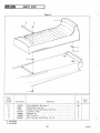
SUSPENSION ASSEMBLY (See figure 6) .. . . ... . .... .. . ... . .
BOLT, HEX, 3/8-24 by 1 IN . LG . .. . .. . . . . . . . . . . . . . . .... .
LOCKWASHER,3/8 ID . .. . .... . . ....... .. ........... .
SPROCKET ASSEMBLY, Drive (See figure 7) ..... . .. . .... ... .
DRIVEN CLUTCH AND MOUNTING ASSEMBLY (See figure 7) .. . .
DRIVEN CLUTCH AND MOUNTING ASSEMBLY (See figure 7) ... .
GAS CAP ASSEMBLY, Tank (See figure 8) . ....... . . ........ .
MAIN FRAME ASSEMBLY . . ........ .... ..... . .... . ... .
BODY STRIP, Wear . . . . . . . . . . . . . . . . . . ....... .. ... .. ..
POP RIVET . .. ...... . . . . . . . . . . . . . . . . . . . . . . . . ......
WASHER·, 3/16 IN . 10 . . . . . . . . . . ... . . . . . . . . . . . .. .. ....
FOOT PAD, LH . . . . . . . . . . . . . . . . . . . . . . . . . . . . . . . . . . . . .
FOOT PAD, RH . . . . . . . . . . . . . . . . . . . . . . . . . . . . . . . . . . . . .
POP RIVET ..... .. ... . . . . . . . . . . . . . . . . . . . . . . . . . .. ..
CABLE TIE ......... . ....... .... . . .. .. .. ... . .... ..
INSTRUCTION MANUAL ASSEMBLY (Not illustrated) ........ . .
INSTRUCTI ON MANUAL ASSEMBLY (Not illustrated) ..... ... . .
PARTS BAG ASSEMBLY, Engine (Not illustrated) .. ...... . . . ..
21
42
41
368
A - SD15M28B
B - SD15M26B
1003632
2
1
1
4
4
1
1
1
1
1
2
31
20
1
1
272
2
*Item 60, Instruction Manual Assembly contains Ski-Dadd ler documentation. Not shown.
* Item 61, Contains metric tools for engine maintenance. Not shown.
17
Model
Code
A
B
A
B
1
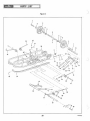
Figure 2
13
23
\
30 27
25
~24
32
)
29
33
18
1003632
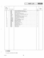
PARTS LIST
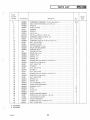
C
r
Figure
& Index
Number
Part Number
2-1
-2
-3
-4
-5
-6
-7
-8
-9
-10
-1 1
-12
-13
-14
-15
-16
-17
-1 8
-19
-20
-21
-22
-23
-24
-25
-2 6
-27
-28
-29
-30
-31
-32
-33
-34
-35
-36
-37
1003280
34984
34271
37045
1003511
132908
9000122
37006
9000122
37005
1003510
37001
37003
37051
37033
37034
9000941
9000555
34992
445170
35011
34271
1003506
1003279
34058
147579
34989
3427 1
35005
9000123
34983
37591
1003461
1003462
1002589
181566
9000191
1003578
Description
Oty
HOOD ASSEMBLY (See figure 1)
CLIP, Hood
RIVET
PLATE, Hood
GAS LID AND HINGE ASSEMBLY
SCREW, RD HD, 10-32 THO by 1/2 IN. LG
LOCKNUT, 10-32 THD
HINGE ASSEMBLY
LOCKNUT, 10-32 THD
SPR lNG, Flat
DECAL, Gas cover
GAS LID ASSEMBLY
BRACKET, Support
RUBBER BUMPER, Gas lid
TRIM STRIP, RH
TRIM STRIP, LH
SCREW, Truss HD, 1/4-20 THD by 5/8 IN. LG
JACKNUT, Molly, 1/4-20
ESCUTCHEON, Side
NUT, Spring
STRIKE
RIVET
HOOD
AI R DUCT, Hood
LOCKNUT, 1/4-20 THD
WASHER
CATCH, Hood
RIVET
GUIDE, Hood
LOCKNUT, 1/4-28 THO
SPACER, Bumper
COVER, Bumper
BUMPE R ASSEM BL Y, RH (See figure 1)
BUMPER ASSEMBLY, LH (See figure 1)
STOP, Hood
SCREW, HEX HO
KLICK PIN
DECAL, Racing
REF
1
3
1
1
2
2
1
2
1
1
1
1
2
1
1
7
7
2
6
2
4
1
1
4
4
2
4
6
6
6
1
REF
REF
1
2
2
2
,
c
A - SD15M28B
B - S015M26B
1003632
19
Model
Code
AB
I~
PARTS LIST
..
)
.
3 (Sheet 1 of 2)
Figure
25 -----...
r
24~
41
44
27
/~
22
L23
~
21
2
20
1003632
~I
c
c
PARTS LIST
ItaSI3~
Figure
& Index
Number
Part Number
Descripti on
Oty
3-1
-2
-3
-4
-5
-6
-7
-8
-9
-10
-1 1
-12
-13
-14
-1 5
-16
-17
-18
-19
-20
·21
-22
-23
-24
-25
-26
·27
-28
-29
-30
·31
-32
-33
-34
-35
-36
-37
-38
·39
-40
-4 1
-42
*37040
33320
181 651
21777
30251
9000125
37041
181 643
21777
9000125
30081
124925
37042
181578
147579
34688
34694
34689
9000123
37231
32185
142443
9000122
32187
9417420
32188
32186
1002782
32286
37159
37486
1003379
1003534
*1003380
18 1608
147579
34688
34694
34689
90001 23
1002984
1003394
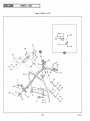
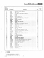
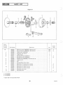
STEERING LINKAGE ASSEMBLY
·.·. ·. ·. ·. ·.· .
ARM, Spind le · . · . · . · . · .
·. ·.·.·.·.·.·.·.·. ·. ·.
BOL T, HEX HD, 3/8-24 THD by 2-3/4 IN . LG · . · . · .
·.· . · .
SPACER · . · . · . . . . . · . · . · . · . · .
·.·.·.·.
·.·.·.·.
SPACER ........ · . · . ... · . · . · .
· .... . . . . · . · . · . · . · ........ .
LOCKNUT, 3/8-24 THD
.
. . .. · . · . · . · . · . · . · .
·.·.
TIE ROD ASSEMBLY · . · . · . · .
· . ·. ·. · .·. · . · .· .· .
BOL T, H EX HD, 3/8-24THD by 1-1/2 IN . LG · . · . · . · .
·.·.
SPACER · .
·.·.·.
· . · . . . . . · . · .·. · . ·.· .
LOCKNUT, 3/8-24TH D
·.·.·.·. . . . . ·. ·. ·. ·. ·. ·. ·.·. ·.
ROD END · . . . . . . . · . . . . . · . · . . . . . · . · . · . · . · . · . .. . . . · .
JAM NUT, HEX, 3/8-24 THD · . ........ · .
·.
·. ·.·.·.·.·.
TIE ROD
.
.
.
.
.
..
·
..
·.·.
·.
· . · . · . .. . . . · . .. . . . · . · . · .
BOL T, HEX HD, 1/4-28 THD by 1-7/8 IN. LG · . · . · . · . · . · . · . · .
WASHER, Plain, 1/4 IN. ID ... · . · . · .. · . · .
·. ·.·.
U-STRAP . . . · . · . · . · . · . · . · . . . . . · .
·.·. ·. ·.·. ·.
WEARPLATE . . . . · . · . . .... . ........ · .
·.·. ·.·.·.·.·.
WEARPLATE
·. · . ·. ·. · . ·. ·. · . ·. · . ·. ·. ·. ·. ·. ·. ·. · .
LOCKNUT, 1/4-28 THD
. . .... · .
·.·.
·.·. ·.·. ·.·.
GRIP, Hand
. . . .. . . . .. · . . . .... · . · . · .
·.·.·.·.·.·.·.·.
THUMB CONTROL ASSEMBLY, Throttle · . · . · . · .
·. ·.
SCREW, RD HD, 10-32 THD by 1-3/8 IN . LG · . · .
·. ·.·.
LOCKNUT, 10-32 THD . · . · .
·. ·.·. ·.·. ·.
LEVER, Thumb . .. · . · . · .
·.
·.
·.
SCREW, Truss HD, 6-32 THD by 3/8 IN. LG
·.·.·.
·.
SPACER · . · . · . . . . . . . . . . . · . . . . . · . · . · . · . · . · . · . · . . . . .
CLAMP, Thumb control
. . . . · . · . · . · ..
·.· . · . · . · . · . · .
KILL-SWITCH ASSEMBLY · . · .
·. ·.·. ·.·.·. ·.·.
CLIP, WIRE
·. ·.
·.·.·.·.·.·.·.·.·.
·.
BRAKE CONTROL A SSEMBLY ... · . · . · .
·.·.·.·.·.·.·.
HAND CONTROL ASSEMBLY · . · . · . · . · . · . · . · .
·. ·.·.
THROTTL E CABLE, HOUSING AND BOOT ASSE MBLY · . · . · . · .
STEER ING HANDLE AND COLUMN ASSEMBLY
·. ·.·. ·.
STEERING COLUMN ASSEMBL Y
·. ·.·.·. ·.·. ·. ·.·.
SCREW, 1/4·28 THD by 1 IN . LG · .
·.·.·.·.
·. ·.·.
WASHER, Plain, 1/4 IN . ID · . · . · . · . · . · . · . · . · . · . · .
·.·.
U-STRAP
·.·.·.. . . . ·.. . . . ·. ·.·.·.·.·. ·.·.·.
WEARPLATE · . · . · . · . · . · . · . · .
·.·.·.·.·.
·.·.
WEARPLATE
· . ·.
·. ·.·.·. ·.·.·.·.·.·.·.
LOCK NUT, 1/4-28 THD
·. ·. · . ·. ·. ·. ·. ·.
·. ·. ·. ·. ·.·.
TACHOMETER · . · . · . · . · .
·.·.·.·.·. ·.·. ·.·. ·.
COV ER, Tachometer
· .·.·.· . ·.
·. ·.·. ·. ·. ·. ·.
2
2
2
4
2
2
2
2
4
2
4
4
2
2
4
1
1
1
2
2
1
1
1
1
2
2
1
1
3
1
1
1
1
1
2
4
1
1
1
2
1
1
-
A - SD15M288
B - SD15M26B
* 3-1 includes applicable items -2 through ·1 3
* 3-34 includes appl icable items ·20 through -33
1003632
21
Model
Code
PARTS LIST
I~
FIgure 3 (Sheet 2 of 2)
49
-------iL
~ - --~
75
58
">.--J
77
22
1003632
~I
c
Figure
& Index
Number
3-43
-44
-45
-46
-47
-48
-49
-50
-51
-52
-53
-54
-55
-56
-57
-58
-59
-60
-61
-62
-63
-64
-65
-66
-67
-68
-69
-70
-7 1
-72
-73
-74
-7 5
-76
-77
-78
-79
c
Part Number
137182
1003391
1003404
137258
37124
34945
30149
33753
33756
1003604
*1003605
*1003606
189329
9000125
37226
*1003607
+*1003608
177923
33748
28762
1003620
181643
274517
9000125
*100362 1
33297
33296
1003616
1003617
*1003619
37250
33729
1003618
33746
1002587
147579
1003609
9000123
1003610
A - SD15M28B
B - SD15M26B
1003632
leSl3~
PARTS LIST
Description
Oty
SCREW, Pan Hd, 6 by 1/4 IN . LG . . . . . . . . . . . . . . . . . . . . . . . . .
BRACKET, Tachometer ..... . ........ . . .... . ...... .. ..
ROLL BAR. . . . . . . . . . . . . . . . . . . . . . . . . . . . . . . . . . . . . . . .
COTTER PIN, 3/16 IN . DIA by 1-3/4 IN . LG
.......... . ... . .
WASHER, Steering co lumn .......... ... ..... .. .........
BUSH lNG, Steering column support .... ..... ..... . . .. .. ...
SPRING, Spindle .......... .. . . . . . . . . . . . . . . . . . . . . . . . .
BUSHING, Plain . . . . . . . . . . . . . . . . . . . . . . . . . . . . . . . . . . . .
BUSHING, Flange ... . .. ......... ..... . . . . . . . . . . . . . . .
SPINDLE . .......... .... ....... .. .... ...... ... ...
SKI AND SPRING ASSEMBLY, RH (See figure 1) . . . . . . . . . . . . . .
SKI AND SPRING ASSEMBLY, LH (See figure 1) .. . . . . . . . . . . . .
SCREW HEX HD, 3/8-24 THD by 3-1/4 IN . LG . . . . . . . . . . . . . . . .
LOCKNUT, 3/8-24 THD . . . . . . . . . . . . . . . . . . . . . . . . . . . . . . .
PAD, Spindle. . . . . . . . . . . . . . . . . . . . . . . . . . . . . . . . . . . . . . .
SPRING ASSEMBLY, RH . . . . . . . . . . . . . . . . . . . . . . . . . . . . . .
SPRING ASSEMBLY, LH .. .. .... . . ... .. . ... . .. .. ......
COTTER PIN ........ .. . . . . . . . . . . . . . . . .. . . . . . . . . . . .
PIVOT PIN, Spring. . . . . . . . . . . . . . . . . . . . . . . . . . . . . . . . . . .
PIN, Pivot ........... . . .. .. . . . . . . . . . . . . . . . . . . . . . . . .
BRACKET ASSEMBLY, Spring mounting . . . . . . . . . . . . . . . . . . .
SCREW, HEX HD, 3/8-24 THD by 1-1/2 IN . LG
............. .
WASHER, Flat, 3/8 IN. ID . . . . . . . . . . . . . . . . . . . . . . . . . . . . . .
LOCKNUT, 3/8-24 THD ...... .. ....... ....... .... .... .
BUMPER ASSEMBLY ... . . . . . . . . . . . . . . .... .... . ..... .
BUMPER .. . . . . . . . . . . . . . . . . . . . . . .... .. ....... . . .. .
PLATE, Spring ......... .. . . . . . . . . . . . . . . . . . . . . . . . . . .
LEAF SPRING, Top . ......... ... ....... .... ......... .
LEAF SPRING, Middle ........... . . . . . . . . . . . . . . . . . . . . .
LEAF SPR lNG, Main . . . . . . . . . . . . . . . . . . . . . . . . .. .... .. .
BUMPER, Main leaf . ........ . . .... .. ..... . ...... . .. . .
SPR lNG, Main lead . ... ....... ........ . ........ . . . ... .
LEAF SPR ING ....... ... . ... . ... . . .... ........... . .
WEAR PLATE, Ski . . . . . . . . . . . . . . . . . . . . ..... .. ....... .
SKI DAMPER ... ...... ..... ..... .... . . . . . . . . . . . . . . .
PLAIN WASHER, 1/4 IN. ID . . . . . . . . . . . . . . . . . . . . .... .. . .
WEAR ROD ASSEMBLY, Ski-weldment . . . . . . . . . . . . . . . . . . . .
LOCKNUT, 1/4-28 THD . . . . . . . . . . . . . . . . . . ... .... . . . .. .
SK I ASSEMBLY . . . . . . . . . . . . . . . . . . . . . . . . . . . . . . ..... .
2
1
1
2
1
1
2
2
2
2
REF
REF
2
2
2
1
1
4
2
2
2
4
4
4
2
2
2
2
2
2
2
2
2
2
2
2
2
2
2
* 3-53 includes applicable items - 57 through -79. For spares, order component parts only.
* 3-57 includes applicable items -61 through -73.
"* 3-65 includes items -66 and -67.
"* 3-70 includes items -71 and -72.
+ For replacement spring assembly order AMF Part No. 1002275.
23
Model
Code
RTS LIST
Figure 4
5
4
JI
I
7-'
Figure
& Index
Number
Part Number
4-1
-2
-3
-4
-5
-6
-7
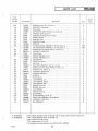
1003270
33395
144815
9413314
1003508
1003503
9000328
Description
SEAT ASSEM BL Y (See figure 1) . . . . . . . . . . . . . . . . . . . . . . . .
RECEPTACLE, Seat clip . . . . . . . . . . . . . . . . . . . . . . . . . . . . . .
SCREW, PAN HD, 6-32 THD by 3/4 IN . LG .. . ..... .... ... ..
LOCKNUT, 1/4-20 . . . . . . . . . . . . . . . . . . . . . . . . . . . . . . . . . .
WASHER, Bar . . . . . . . . . . . . . . . . . . . . . . . . . . . . . . . . . . . . .
NUT, Tinnerman . . . . . . . . . . . . . . . . . . . . . . . . . . . . . . . . . . .
BOLT, Carriage, 1/4-20 THD by 1-IN. LG . . . . . . . . . . . . . . . . . . .
Oty
.
.
.
.
.
.
.
Model
Code
REF
2
4
2
2
2
2
A - SD15M28B
B - SD15M26B
24
1003632
PARTS LIST
c
Figure
& Index
Number
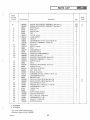
5-1
-2
-3
-4
-5
-6
-7
-8
c
-9
-10
-11
-12
-13
-14
-15
-16
-17
-18
-19
-20
-21
-22
-23
-24
-25
-26
-27
-28
-29
-30
-31
-32
-33
-34
-35
-36
-37
-38
r
Part Number
Descript ion
Oty
*1003291
*1003290
38058
34709
30489
37529
1003317
+1002431
124920
138538
1002460
443003
1002423
38383
1002421
38208
1002533
1002465
1002462
1002461
1002423
38383
1002463
38200
9000122
453284
1003035
216278
120380
30270
1002662
1002660
189348
120396
138549
37183
32588
1003520
1002665
181568
120380
120613
1002689
ENGINE AND SUPPORT ASSEM BLY (See figure 1)
· .·.·.
ENGINE AND SUPPORT ASSEMBLY (See fi gure 1) · . · .
·. ·.
SPARK PLUG
.... . . · . · . · . · . · . · . · . · . · . · .
·.·.·.·.
GAS LIN E
·.·.·.·.. . . . ·.·.·.·.·.·.·.·.·.·.·.·.·.
HOSE CLAMP · . · . · .
·. ·.·.·.
· . . .... . · . · . · . · . · . · .
TE E ........
.
.
.
.
·.
·.·.·.·.·.·.·. ·. ·.·.·.·.·.·.
FIL TER, In-Line · . · . · . · . · .
·.·.·.·.·.·. ·. ·.·.·.
CARBURETOR
· . · . · . ·. · . · . ·. ·. ·. ·. · . · . ·.
JAM NUT . . · . · . · . · . · . · .
· . · . · . ·. ·. · . · . ·. · . · . · .
LOCKWASHER , Internal tooth, 5/16IN . ID · . · . · . · . · . · . . .. .. . · .
MANIFOLD ASSEMBLY, Intake, RH · . · . · . · . · . · . · . · . . .... . · .
PIN, Groove
·. ·.
·.·. ·.·.·.·.. . . . ·. . . . ·.
NIPPLE, Impulse · . · .
· . · . ·. · . ·.· . · . . . . . · . · . · . .
STUD
·.·. · . · .· . · . ·. ·. · . · . · . · . ·. ·. ·. ·. . . . . ·.
CAM ASSEMBLY
·.·.
·.·. ·.·.·.·.·.·. ·.·.
BEAR lNG, Flange . . .
·.·.
·. ·. ·. ·. · .· . · . ·.· .
THROTTLE ARM ASSEMBLY · . . . . . . . . . · . · . · . · . · . · . . . . .
TH ROTTLE SHAFT . .
·.. . . .
·.·.
·.· .·. ·.·.
MANIFOLD MACHINING, Intake, RH
· . ·. · . ·. ·.·. · .·. · .
MANIFOLD ASSEMBLY, Intake, LH · . · . · . · . · . · . · . · . · . · . · .
NIPPLE, Impul se · . . . . .
·.·.. . . . ·.
·. ·.
·.
STUD
..
·.
·.·. ·.·.·.·.·.·.
·. ·. ·.
MANIFOLD MACHINING, Intake, LH
·.·. ·. ·. · . ·. ·. ·.
SCREW, Throttle
·.
·.
·.·.·.·. ·. · . ·.
LOCKNUT, 10·32 THO · .
· . · .·.·.·.·.·.·.
·.·. ·.
NUT, 10-32 THO · . · . · . · . · . · . · . · . · . · . · . · . · . · . · . · . · . · .
SHIELD, Carburetor · . · . · . · .
·.·.·. ·.·.·.·.·.·.
CAPSCREW, SOC HD, 1/4-20 by 1/2 IN. LG
·.· . ·. ·.
·.·.
LOCKWASHER, Spring . . · . · . · . · . · . · .
·.·. ·.
·. ·.
IMPULSE LINE · . · .
.. ·.·.·.·.·.·.·. ·.·.·.·.·.·.
DRIVE CLUTCH, 780 M (See figure 10) · . · . · . · . · . · . · . · .
·.
DRIVE CLUTCH, 780 M (See figure 10) · . · .
·.·. ·.
ADAPTER BOLT, Clutch · . · . · . · . · . .' . · . · .
·.·.·.
WASHER, Plain, 17/32 10 by 1-1/1600 · . · . · . · .
·.·. ·.·.
LOCKWASH ER, 1/2 ID
·.
·.
·.·. ·.·. ·.·. ·.
TUBING, Flex · . · . · . · . · . · . · . · .
·.
·.·. ·.
CLAMP . . . .
·.·.·.·.·.·.·.·.·. ·. · .·.·. ·. ·.·. ·.
MUFFLER WELDMENT · .
·.·.
·.
EXHAUST MAN I FOLD
·. ·.
·. · . ·.· . · . · .
BOL T, HEX HD, 1/4-28 THO
·. ·. ·.·. ·.·. ·.·.·. ·.·.
LOCKWASHER, 1/4 10
·.·. ·.·. ·.·. · .·.·.·. ·. ·.
JAM NUT, 1/4-28 THO
·.·.
·.·. ·.·.·.·.·.·.
SHROUD, Modified · . · .
·.·.
·.·. ·.·.·. ·.
REF
REF
2
4
12
1
2
2
4
4
1
2
1
2
1
2
1
1
1
1
1
2
1
2
2
6
1
2
2
2
1
1
1
1
1
1
2
1
1
1
1
1
1
A - SD15M28B
B - SD15M26B
* For spares, order components only
+ Carburetor Repair Kit No. 1002989
100363 2
25
Modei
Code
A
B
A
B
23
SUPPLIED
r::
WITH ENGINE
)2 21
~
\
\ 18
~~~tl'l.\
~
N
17;;
' .~
'~'3\/ ~
,3
43~
2
~
~~~ ~ ~
11
.~.......::;
~r .•~ ______
-'~)~
42-i-_-i
\ \"
0
'~\~---:Ar
\
~2
i A e:=:
/l\\-3
5
2
~.
.
31
~ 46
L45
39
...
o
o
CAl
Ol
CAl
N
....
....C;;
".
'-./"
i'\ ,
=;;:
~ / r~ U
--:'--{1 ",0" i,
33
0)
20
~
~~,
\
8 7
."
cE'
c
ca
U'I
~I
c
Figure
& Index
Number
Descript ion
Oty
37596
9000327
371 26
37595
90001 24
1002542
180175
120384
1002786
1003302
1003303
1003315
2791
1003286
1002692
MOUNTING STRAP, Machining
· . · . · . · . · . · . · .. · .
·.
BOL T, Carriage , 5/16-24 by 1-1/4 IN . LG · . · . · . · . · . · . · . · . · . · .
BAR WASHER
· . · . ·.
·.·.·. ·. ·. ·. ·.
PLAIN WASH ER, 13/32 ID by 1-1/2 OD · . · . · . · . · . · .
·.·.·.
LOCKNUT, 5/1 6-24 TH D · . · . · . · . · . · . · . · . · . · . · . · . · .
·.
BASE EXTRUSION, Engine. · .
. . ... · . · . · .
·.
BOLT, HEX HD, 1/2-13 by 1-1/4 IN . L G · . · ... · . · . · . · . · · . · .
LOCKWASHER, Spring, 1/2 IN . ID · . · . · . · . · . · . · . · . · . · . · . · .
LOCKWASHER, Spring · . · . · . · . · . · . · .
·.·.·.·.·.·.·.
ENGINE ,292 · . .. · . .. · . .. · . · ..... · . · . · . .... · . · . · . · .
EN GINE, 340 · ... · .
· . .. · . . . · . · . · . · . · . · . · . .. · .
..·.·. ·. ·.· .
DECAL
· . .. · .
·.
·.
·.·.
CLIP . . . .
·. ·.·. · . ·. ·. ·. ·. · . · . · .· . · .· .
Wiring Connecti ons, Engine · ... · ...
· . · . · . .. · . · .
CLAMP . . . · . · .
· . · . · . · . · ... · . · . · . · . · . · .
·. ·.
2
4
2
4
4
1
4
4
8
1
1
1
1
1
1
-49
-50
-51
-52
.
c
A - SD 15M28B
B - SD 15M26B
1 0 03632
IM SI 3ij
Part Number
5-39
-40
-41
-42
-43
-44
-45
-46
-47
-48
c
PARTS LIST
27
Model
Code
A
B
PARTS LIST
I ~F
)
Figure 6
,( .
36
\
35
28
1003632
~I
c
-(
C
Fi gure
& Index
Number
Part Number
6-1
-2
-3
-4
-5
-6
-7
-8
-9
-10
-11
-12
-13
-14
-1 5
-16
-17
-18
-19
-20
-21
-22
-23
-24
-25
-26
-27
-28
-29
-30
-31
-32
-33
-34
-35
-36
-37
-38
-39
-40
-41
-42
-43
-44
1003597
9000592
1002890
1003441
131017
1002850
1002844
9421 234
9000284
125529
1002888
271501
120383
1002604
1003457
1002820
706
1002849
1002825
1002388
1003487
189333
1003456
192481
1003444
120377
1003443
120377
189333
1003456
192481
1002816
1002817
1002604
1002853
1003442
9000825
1002819
9000826
1003595
181637
131099
1003445
181675
454012
Description
SUSPENSION ASSEMBLY, 15- lnch (See figure 1) · .
BOL T , HEX HD, 5/16-24 by 4-1/4 IN. LG ..... . · .
WASHER · . · .
·. ·. ·.·. ·. ·.·.·.·.
WHEEL, Molded · . · .
. .. . · .
· . · . ·. · .
WASHER · . · .
·.·.
·. ·. ·.·. · . ·.
SPACER .. . .. . · . · . · .
· . · .·. · . · . ·. · .
AXLE, Rear
·.
·.·.·.·. ·.
PIN, Drive, 5/32 by 1-1/4 IN . LG
·.
SETSC REW, 3/8-24 by 3/8 IN . LG
·. ·.·.·.
NUT, 7/16-14 THD · .
·.·.
·.·.
·.
CAPSCREW, HEX HD , 7-16-14 by 4 IN. LG · . · . · .
NUT, 7/16-14 THD · . · . · . · . · . · . · . · . · . · . · .
WASHER, 7/16 OD
·. ·.·.·.
AXLE ASSEMBLY, Inner · .
·.
·.·. · .
REAR ARM WELDM ENT
·.·.·.·.·.·.·. ·.
BUSH lNG, Nylon · .
· . · . · .. · . . . . · . · . · .
GREASE FITTING
· . · . · . · . · ... . · . · . · . · .
REAR ARM, Inner
· . · .. . · . · ... · . · . · .
INSERT, Pivot · .. . · . · . · . · . · . · . · . · . · .
·.
SPRING, LH · . · .. · . · . · . · . · . · .. · . · . · .
SPRING , RH
·.·.·.
·. ·. ·. ·. ·. ·. ·.
SCREW, HEX HD, 3/8-24 by 4-1/4 IN. LG
·.
WASHER, Carriage spring
·.·.·.·.·.
·.
NUT, 3/8-24 THD
.. ·.·. ·. ·. ·. ·. ·.·.
EY EBOLT · . · . · . · . . . · .
·.
·.·.
NUT, 3/8-16 TH D
·.·.
·.·.·. ·.·.
EYEBOLT
·. ·.·. ·. ·. ·. · . ·.·. ·. · . ·.
NUT, 3/8-1 6 THD
·.·.
·. ·. ·.·.
SCREW, HEX HD, 3/8-24 by 4-1/4 IN. LG · . · . · .
WASHER, Carriage spring · . · . · . · . · .
·.·. ·.
NUT, 3/8-24 THD
· . · .. . · ... · . · . · . · . · . · .
SPRING , LH . . . · .
. .. .. · . · . · . · . · .
·.
SPRING, RH · . · .
·
.
·
. ·.·.·.·.·.·.·.
·.
AXLE ASSEMBLY, Inner
·.
·.·.·.
FRONT ARM WELDMENT · .
·.·. ·.·. · .
RUNNER, Hi -Fax
·. ·.·.· .
·. ·.
RIV ET . .
·. ·.
·. ·. · . · . · . -.
PAD, Small
·.·. ·.·.·. ·.·. ·.
· . -.
RIVET . . · .
· . -.
·.·. ·.·.·.
SKID FRAME WELDMENT . · .
-.
·.
SCR EW, HEX HD, 3/8-24 by 1 IN . LG · .
·.
LOCKWASHER, 3/8 aD · . · . · . · . · . · . · . · .
SHOCK ABSORBER
·.
· . . . .. .. · . · . · .
SCR EW, HEX HD, 7/16-20 by 2-1/4
·.
NUT, 7/16-20 THD
· . · . .... .... · . · .
·.·.·.
A - SD15M28B
B - SD1 5M26B
1003 632
PARTS LIST
29
leS l a~
Oty
·.·.·.·.·.·.
.·.·.·.·. ·.
·.·. ·.·.·.
·. · . ·. · . · . ·.
· . · . ·. ·.
· . · . ·. ·. · . · .
·. ·.·.
·.
·. ·.·. ·. ·.
·.· . ·. ·. · .
· .. . · . · . · . · .
·.·. ·.·.·.
·.·.·.·.·. ·.
·.·.·.·.
·. · . · . ·. · . ·.
·.·.·. · . ·. ·.
· . · . · . · . ..
·. ·.·.·.·.
· . · . · . · . .. · .
·.·.·. ·.·.·.
·. ·.·. ·.
·. · . ·. ·. ·. ·.
·.·. ·.·.
·. ·. ·. ·.·.
·. ·.·.·.·.
·.·. ·.
.. ·.·. ·.
·.·.·.·.
·. ·.·. ·.
· . ·. ·. ·. ·.
·.·.·.·.·.
·.·.·.·.·.
·. ·.·.·.·.
·.·. ·.·.·.
· . · . · .. . · .
·.·.
· . · .... .
·
.
·
.
·. · . ·.
·.
·.·.
·.
·.
· . · . ·. ·. · .
·.·.·. ·. ·.
·. ·.·.
·.·.·.
·. ·. ·.·.·.
... · . ·.
·.·.·.·.·.·.
·.·.·.·.
·
REF
2
2
2
2
2
1
2
2
2
2
2
2
1
1
2
2
2
4
1
1
2
2
2
2
4
2
4
2
2
2
1
1
1
1
2
34
8
16
1
4
4
1
2
2
Model
Code
)
Figure 7 _ _ _ _ _ _ _ __
24
33
62
--- --<'»
r
3
~
2
4
52
1003632
~I
c
Figure
& Index
Number
Part Number
Description
Oty
1002018
37141
137258
35042
34629
180078
37440
*1003491
*1003492
1003405
272726
9000125
34277
119120
125250
9417098
34628
34636
147664
120393
9000124
34645
1003501
217921
9000122
272686
106751
1002703
180077
138538
1002125
1002124
1002126
1003075
37880
1003589
1003493
181 643
120382
37253
9000124
34826
273938
34950
CHAIN COVER, Top . . . . . . . . . . . . . . . . . . . . . . . . . . . . . . . . .
ROLLER CHAIN, 35·2, 102 pitch. . . . . . . . . . . . . . . . . . . . . . . . .
COTTER PIN, 3/16 IN. by 1-3/4 IN . LG ...... .. ... ... ... . . .
SPROCKET, 35-2, 45 teeth .... . . ... . .. . ... ..... . .......
SPACER. . . . . . . . . . . . . . . . . . . . . . . . . . . . . . . . . . . . . . . . . .
BOLT,HEXHD,5/16-18THDby7/8IN.LG.................
WASHER, Chain cover ..... . ....... ...... ..... .. ......
DRIVEN CLUTCH AND MOUNTING ASSEMBLY (See figure 1) . . . .
DR IVEN CLUTCH AND MOUNTING ASSEMBLY (See figure 1) .. . .
ROD TENSIONER, Clutch ....... . . . .. .. . . ... ...... . . ..
STUD, 3/8-24 THO by 1-1/2 IN . LG . . . . . . . . . . . . . . . .. ......
LOCKNUT, 3/8-24 THO. . . . . . . . . . . . . . . . . . . . . . . . . . . . . . .
SPROCKET, 35-2, 19 teeth .. ... . . .... .. ....... ... ......
COTTER PIN, 3/32 IN . by 1-1/4 IN. LG . ... . . . . . . . . . . . . . . . .
NUT, Slotted , 1/2-20 THO. . . . . . . . . . . . . . . . . . . . . . . . . . . . . .
WASHER, Flat, 17/32IN.by lIN . OD . . . . . . . . . . . . . . . . . . . . .
SPACER. . . . . . . . . . . . . . . . . . . . . . . . . . . . . . . . . . . . . . . . . .
CLAMP, Bearing ... ..... . . . . . . . . . . . . . . . . . . . . . . . . . . . .
STUD . . . . .. . . . . . . . . . . . . . . . . . . . . . . . . . . . . . . . . . ....
WASHER, 11/32 IN. 10 by 11/16 IN. 00 ..... . . . . . . . . . . . . . . .
LOCKNUT, 5/16-24 THO ... .. ... .. ...... . .. . . .. . ..... .
BEARING, Driven clutch . . . . . . . . . . . . . . . . . . . . . . . . . ... .. .
HUB AND DISC ASSEMBLY . . . . . . . . . . . . . . . . . . . . . . . . . . . .
SCREW, 10-32 THO by 5/8 IN. LG ......... . . . . . . . . . . . . . . .
LOCKNUT, 10-32 THO .. .. .... ..... ........ . .... .. ... .
LOCKNUT, 3/4-16 THO . . . . . . . . . . . . . . . . . . . ....... . ... .
KEY, Woodruff, No. 9, 3/16 IN . by 3/4 IN. LG .. . . . . . . . . . . . . . .
DISC BRAKE ASSEMBLY
............ . . ...... ..... . . .
BOLT, HEX HD, 5/16-18 THO by 3/4 IN. LG . . . . . . . . . . . . . ...
LOCKWASHER, Internal tooth . . . . . . . . . . . . . . . . . . ........
BRAKE BRACKET . . . . . . . . . . . . . . . . . . . . . . . . . . .... ....
ARM, Brake bracket . . . . . . . . . . . . . . . . . . . . . . . . . . . . . . . . . .
CALIPER, Disc brake . . . . . . . . . . . . . . . . . . . . . . . . . . . . . . . . .
PUCK, Brake. . . . . . . . . . . . . . . . . . . . . . . . . . . . . . . . . . . . . . .
BELT, Variable-speed . . . . . . . . . . . . . . . . . . . . . . . . . . . . . . . ..
DRIVEN CLUTCH AND SHAFT ASSEMBLY (See figure 9)
..... .
DRIVEN CLUTCH MOUNTING. . . . . . . . . . . . . . . . . . . . . . . . . .
BOLT, HEX HD, 3/8·24 THO by 1-1/2 IN . LG ...... . .. . ......
LOCKWASHER, Spring, 3/8 IN. 10 . . . . . . . . . . . . . . . . . . . . . . . .
WASH E R, Serrated . . . . . . . . . . . . . . . . . . . . . . . . . . . . . . . . . . .
LOCKNUT, 5/16-24 THO . . . . . . . . . . . . . . . . . . . . . . . . . . . . . .
R lNG, Circular push-on . . . . . . . . . . . . . . . . . . . . . . . . . . . . . . . .
PIN, Spring. . . . . . . . . . . . . . . . . . . . . . . . . . . . . . . . . . . . . . . .
CAM, Right side. . . . . . . . . . . . . . . . . . . . . . . . . . . . . . . . . . . . .
1
1
1
1
1
1
1
REF
REF
1
1
1
1
1
1
1
1
2
4
7-1
-2
-3
-4
-5
-6
-7
l
c
-8
-9
-10
-11
-12
-13
-14
-15
-16
-17
-18
-19
-20
-21
-22
-23
-24
-25
-26
-27
-28
-29
-30
-31
-32
-33
-34
-35
-36
-37
-38
-39
-40
-41
-42
A - SD15M28B
B - SD15M26B
* For spares, order individual components.
1003632
INSI3~
PARTS LIST
31
4
4
2
1
6
6
1
1
1
2
2
1
1
1
2
1
1
1
2
2
1
1
1
2
1
Model
Code
A
B
PARTS LIST
)
Figure
& Index
Number
Part Number
Description
7-43
-44
-45
-46
-47
-48
-49
-50
-51
-52
-53
-54
-55
-56
-57
-58
-59
-60
-61
-62
-63
-64
-65
34952
9417098
34965
37024
9000322
9000321
9000124
1003495
*1003370
34648
30079
1003369
1002516
1003367
1003377
181608
442826
1003368
1003373
9000394
1002734
1002992
138485
CAM, Left side .... ........ . ........... . ... . ... . ...
WASHER, Plain, 17/32 IN . 10 by 1 IN. 00 .. . . . . . . . . . . . . . . . .
SHAFT, Clutch mounting .... ... .. . ..... .. ........... .
BEAR IN G RETA IN ER AND PLATE ASSEMBLY ...... ... . . ..
BOLT, Carriage, 5/16-24 THD by 3/4 IN. LG . . . . . . . . . . . . . . . .
BOLT, Carriage, 5/16-24 THD by 5/8 IN . LG ...... . ...... . ..
LOCKNUT, 5/16-24 THO .. ..... ....... ......... ..... .
CHAIN COVER ASSEMBLY, Bottom ....... ...... . .......
DRIVE SPROCKET ASSEMBLY, 15-inch (See figure 1) . . .......
BEAR lNG, 25 MM bore . . . . . . . . . . . . . . . . . . . . . . . . . . . . . .
SEAL, Grease . . .... ....... .. ........ .. . . . ... . ... . .
DRIVE SHAFT ASSEMBLY . . . . . . . . . . . . . . . . . . . . . ......
SET COLLAR (with 5/16-18 THD by 1/4 IN . LG cup-point setscrew)
WH EEL, Idler ...... ... .. .. . . . . . . . . . . . . . .... . . . .. . .
FLANGE, Sprocket .. .. .......... .... ..... . .........
SCREW, 5/16-24 THD by 1 IN. LG ... ..... . . . .. .. ....... .
LOCKNUT, 5/16-24 THD .... ...... . .......... . . ... ...
SPROCKET . . . . . . . . . . . . . . . . . . . . . ...... . ... .... .. .
DRIVE SHAFT ASSEMBLY ... .. ....... .. ....... . .. . . .
LOCKNUT, 5/16-18 THD . . . . . . . . . . . . . . . . . . . . . . . . . . . . .
SLEEVE .... . . . . . . . . . . . . . . . . . . . ... , . . . . . . . . . . . . . .
SPACER . .... . ........... .. ... . . . . . . . . . . . . . . . . . ..
LOCKWASHER, External tooth, 5/16 ID .... .... . .... .. . ...
Oty
.
.
.
.
.
.
.
.
.
.
.
.
.
.
.
.
.
.
.
.
.
.
Model
Code
1
1
1
2
3
3
6
1
REF
2
2
1
2
2
2
10
10
2
1
1
1
3
2
A - S015M28B
B - SD15M26B
*For spares, order applicable items 7-49 through 7-58 only .
32
1003632
~I
c
Figure
& Index
Number
Part Number
8-1
-2
-3
-4
-5
-6
-7
-8
-9
-10
-11
-12
-13
-14
-15
-16
-17
-18
-19
37683
*37265
37684
37357
181566
147579
37213
144107
1002648
1002649
1003345
1003348
1003344
37524
37525
34154
37259
37418
37636
Description
GAS CAP ASSEMBLY (See figure 1)
·.·. ·.
GAS CAP AND INDICATOR ASSEMBLY
·.·.
GASKET, Gas cap
·.·.·. ·. ·.·.·.
SPILL CHUTE, Weldment, gas
·. ... ·. ·.
BOLT, HEX HD, 1/4-28 THD by 3/4 IN . LG · . · .
WASHER, Plain
·.
· . · ... · . · . · .
VENT AND PRESSURE RELIEF VALVE
PIPE REDUCER, 1/4 to 1/8 IN . · . · .
·. ·.
GAS LIN E, Tank-To-Carburetor · .. . · . · .
COVER, Gas line
· . ·. ·. ·. ·. ·. ·.·.·.
GAS LINE ASSEMBLY, Tank
·. ·.·. ·.·.
GAS LINE, Gas tank · .. · . · . · . · . · .
·.
WEIGHT, Fuel tand · . · .
·.·.·.·.·.·.
GAS OUTL ET, Gas tank
·. ·.
·.·.·.·.·.
RING, Retaining
·.
·.·.
GASKET, Gas tank outlet · . · . · . · . · . · . · . · .
GAS TAN K, Plastic · .
·. ·.·.·.·.·. ·.
PAD, Gas tank . . . . • . · 0 • · . · . · .
·.·.
PAD, Gas tank . . . . · . · .
·.·.·.
·.
c
c
A - SD15M28B
B - SD15M26B
* For spares, order AMF Part No. 37683.
1003632
PARTS LIST
33
leSid~
Oty
·. ·.
·. ·.·. ·.
· . · . · . · .. .
·.·.·.·.·.·.
· .·.
·.·. ·.
·.·.·.·.·. ·.
·.·. ·. ·. ·. ·.
·
.·.
·. ·.·.
· .·.·.
·.
·.·.·.
·.·.·.
· .·.·.
·.·.
·. ·. ·.
·.·.
·.·. ·. ·. ·. ·.
·. ·.·.
·.
·. ·.
·.·.·.·.
·.
·.·.
·.·.
·.·.·.
·. ·. ·. ·.·. ·. ·.
REF
1
1
1
2
2
1
1
1
1
1
1
1
1
2
1
1
2
6
Model
Code
PARTS LIST
I~
)
Figure 8
1--+--- 10
+-,.
@r-16
~::
l-13
I
@,
11
15
17
)
34
1003632
~I
r
PARTS LIST
Figure 9
2
I
L-~
7
c
Figure
& Index
Number
9-1
-2
-3
-4
-5
-6
-7
Part Number
Description
Oty
1003589
37607
100304 1
1002573
37603
1002572
37610
1003074
DRIVEN CLUTCH AND SHAFT ASSEMBLY (See figure 7) . . ... . .
FIXED FACE AND HUB ASSEMBLY . . . . ..... . .. .. . . . . . . · .
MOVABLE FACE ASSEMBLY . ... . .. . . . . . . . . . . · . .. . . ...... .
SPR ING .... .. . .... . . . . . . . . . . . . . . . . . . . . . . . . . . . . . . . . . . . .
KEY, Morton Hi-Pro
. . . . . . . . . . . . . . .... . ...... · . . . . . .... . .
TORQUE BRACKET ASSEMBLY ... .... ........ . . . . . . . . .. . . . . . . .
RING, Retaining . .................... . . . . . . . .. . . . . . . . · . . . . . . . · .
CAM, Slipper ... .. . . . . . . . . . . . . . . . . . . .. . . . . . . . . . . . . . · .
REF
1
1
1
1
1
1
3
A - SD15M28B
B - SD15M26B
c
1003632
35
Model
Code
I ~F
PARTS LIST
)
Figure 10
5
4
6
3
7
~.
=
11
Figure
& Index
Number
Part Number
Description
1002662
1002660
1003062
1002560
1002561
1003061
1003561
1003060
1003063
*1002564
1002562
1003081
1003628
1003080
1003629
1003089
1002559
DRIVE CLUTCH ASSEMBLY (See figure 5) . . . . . . . . . . . . . . . . .
DRIVE CLUTCH ASSEMBLY (See figure 5) . . . . . . . . . . . .... .
FIXED FACE ASSEMBLY . . . . . . . . . . . . . . . . . ... . .... . ..
WASHER, Idler bearing . . . . . . . . . . . . . . . . . ... . .... .. . ...
LINER, Spline ..... .. . . . . . . . . . . . . . . . . . . . . . . . . . . . . . .
MOVABLE FACE ASSEMBLY ..... . .. ... . . . . . . . . . . . . . ..
MOVABLE FACE ASSEMBLY . . . . . . . .. . . ..... . . .. ......
RAMP PLATE ASSEMBLY (Includes item 6) . . . . . . . . . . . ... ..
LOCK PLATE . . . . . . . . . . . . . . . . . . ... . . . . . . . . . . . . . . . .
NUT . . . . . . . . . . . . . . . . . . ... ... .. .. . . . . . . . . . . . . . . .
RETRACTOR, Roller weight .. ... .... . . . . . . . . . . . . . . . . . .
SERVICE KIT, Springs, pins, bushings . . . . . . . . . . . . . . . . . . . . .
SERVICE KIT, Springs, pins, bushings .... .. ... ....... ... ..
SERVICE KIT, Roller arm assy . . . . . . . . . . . . . . . .. . . . . . . . ..
SERVICE KIT, Roller arm assy ..... . . . . . . . . . . . . . . . . . . . .
WASHER, Ramp plate ...... ..... . . ..... ... . . . . . . . . . .
BEARING; Idler . . . . . . . . . . . . . . . . . . . . . . . . . . . . . . . . ... .
10-
-1
-2
-3
-4
-5
-6
-7
-8
-9
-10
-11
-12
Oty
.
.
.
.
.
.
.
.
.
.
.
.
.
.
.
.
.
REF
REF
1
1
6
1
1
1
1
1
Model
Code
A
B
A
B
1
1
1
1
1
1
A
B
A
B
1
B
A - SD15M28B
B - SD15M26B
* Apply 125 ± 15 foot-pounds torque .
36
1003632
c
NUMERICAL LIST
Part No.
1002018
1002124
1002125
1002126
1002421
1002423
1002431
1002460
1002461
1002462
1002463
1002465
1002471
1002516
1002529
1002533
1002542
1002560
1002561
1002562
1002564
1002572
1002573
1002587
1002589
1002604
(
1002642
1002648
1002649
1002660
1002662
1002665
1002689
1002692
1002703
1002734
1002782
1002786
1002803
1002808
1003632
Figure
& Index
Number
7-1
7-30
7-29
7-31
5-12
5-10
5-17
5-6
5-8
5-16
5-16
5-19
5-15
1-20
7-55
10-10
5-14
5-44
10-2
10-3
10-8
10-7
9-5
9-3
3-75
2-34
6-13
6-73
1-54
8-9
8-10
5-27
105-27
105-34
5-38
5-52
7-26
7-63
3-28
3-29
5-47
1-41
1-43
Oty
Part No.
1
1
1
1
1
1
1
2
1
1
1
1
1
1
2
1
1
1
1
6
1
1
1
1
2
1
1
1
2
1
1
1
1002816
1002817
1002819
1002820
1002825
1002844
1002849
1002850
1002853
1002888
1002890
1002984
1002992
1003035
1003041
1003060
1003061
1003062
1003063
1003074
1003075
1003080
1003081
1003106
1003107
1003270
1003272
1003274
1003275
1003279
1003280
REF
1
REF
1
1
1
1
1
1
3
8
21
41
1003286
1003289
1003290
1003291
1003302
1003303
1003315
1003316
1003317
1003344
Figure
& Index
Number
6-31
6-32
6-37
6-15
6-18
6-6
6-17
6-5
6-34
6-10
6-2
3-11
7-64
5-23
9-2
10-5
10-4
10-1
10-6
9-7
7-32
10-10
10-9
111-13
41-53
1-60
1-60
2-23
1-2
25-51
1-38
1-25
51-25
55-48
5-48
5-49
1-19
5-5
8-13
Oty
1
1
8
2
4
1
2
2
1
2
2
1
3
1
1
1
1
1
1
3
2
1
1
1
1
1
REF
1
1
1
1
1
REF
1
1
1
REF
1
REF
1
1
1
1
2
1
I~
PARTS LIST
Part No.
1003345
1003348
1003353
1003366
1003367
1003368
1003369
1003370
1003371
1003373
1003377
1003379
1003380
1003391
1003394
1003404
1003405
1003433
1003434
1003441
1003442
1003443
1003444
1003445
1003456
1003457
1003461
1003462
1003487
1003488
1003491
1003492
1003493
1003495
1003501
1003502
1003503
1003506
1003508
1003510
1003511
Figure
Figure
& Index
& Index
Number
8-11
8-12
1-18
1-16
7-56
7-60
7-54
7-51
1-40
7-61
7-57
3-32
3-34
3-44
3-42
3-45
7-8
1-46
1-45
6-3
6-35
6-26
6-24
6-42
6-22
6-14
1-3
2-32
1-4
2-33
6-20
6-19
1-51
7-7
1-51
7-7
7-35
7-50
7-21
1-14
4-6
2-72
4-5
2-10
2-4
Oty
Part No.
Number
Oty
1
1
1
1
1
2
1
1003520
1003525
1003534
1003561
1003577
1003578
1003589
5-33
1-1
3-33
10-4
1-33
2-37
7-34
96-39
1-47
63-52
1-11
3-53
1-12
3-53
3-57
3-57
3-77
3-79
3-68
3-69
3-73
3-70
3-61
3-65
10-9
10- 10
7-25
7- 12
6-25
6-27
5-25
5-36
7-37
6-12
5-46
1-36
7-18
1-9
5-29
5-37
5-7
3- 12
7-1 3
1
1
1
1
1
2
1
REF
1
1
2
1
1
1
1
1
1
1
2
2
2
2
2
1
2
1
1
REF
1
REF
1
1
1
1003595
1003597
1003604
1003605
1003606
1003607
1003608
1003609
1003610
1003616
1003617
1003618
1003619
1003620
1003621
1003628
1003629
106751
119120
120377
120380
REF
1
REF
1
1
1
1
2
1
2
1
1
120382
120383
120384
120392
120393
120394
120396
12061 3
124920
124925
125250
REF
1
1
REF
2
1
REF
1
REF
1
1
2
2
2
2
2
2
2
2
1
1
1
1
4
4
2
1
2
2
4
4
4
4
1
1
4
4
1
1003 6 32
RTS LIST
c
Part No.
125529
131017
131099
132908
137182
137258
138485
138538
138549
142443
144107
144815
147579
c
147664
177923
180077
180078
180175
181566
181568
181577
181578
181608
181637
181643
181648
181651
181675
189329
189333
c
1003632
Figure
& Index
Number
6·9
6·4
1·49
6-41
2·5
3·43
3-46
7·3
7·65
5·8
7·28
5·30
3·22
8·8
4·3
1·23
2·25
3·15
3·36
3·76
8·6
7·17
3·58
7·27
7·6
5·45
1·22
2·35
8·5
5·35
1·21
3·14
3-35
7·58
1-48
6-40
3·8
3·62
7·36
1·8
3·3
6-43
3·54
6·21
6·28
Oty
Part No.
2
2
4
4
2
2
2
1
2
4
2
1
1
1
4
4
4
4
2
2
2
4
4
2
1
4
1
2
2
1
2
2
2
10
4
4
2
4
2
2
2
2
2
2
2
189348
192481
Figure
& Index
Number
216278
21777
21792 1
271501
272686
272726
273938
274517
279 1
28762
30079
30081
30149
30251
30270
30489
30696
30697
32185
32186
32187
32188
32528
32532
32588
33296
33297
33320
33395
33729
33746
33748
33753
33756
33768
33769
33808
34058
34154
34271
•
5·28
6·23
6·30
5·24
3-4
3·9
7·22
6·11
7·24
7·9
7-41
3·63
1·39
5·50
3·60
7·53
3·1 1
3-49
3·5
5·26
5·3
1·57
1·57
3·21
3·27
3·24
3·26
1·29
1·28
5·31
3·67
3·66
3·2
4·2
3·72
3·74
3·59
3·50
3·51
1·26
1·30
1·6
2·24
8·16
2·2
Oty
1
2
2
2
4
4
6
2
1
1
2
4
1
1
2
2
4
2
2
2
12
1
1
1
1
1
1
4
4
2
2
2
2
2
2
2
2
2
2
4
4
4
4
1
3
Part No.
34271 (Cant.)
34277
34628
34629
34636
34645
34648
34688
34689
34694
34709
34826
34945
34950
34952
34965
34983
34984
34989
34992
35005
35011
35042
37001
37003
37005
37006
37024
37033
37034
37040
37041
37042
37045
37051
37124
37126
37141
37159
37183
Figure
& Index
Number
2-21
2-27
3-40
7-11
7-15
7-5
7-16
7-20
7-52
3-16
3-37
3-18
3-39
3-17
3-38
5-2
7-40
3-48
7-42
7-43
7-45
2-30
2-1
2-26
2-18
2-28
2-20
7-4
2-11
2-12
2-9
2-7
7-46
2-14
2-15
3-1
3-7
3-13
2-3
2-13
3-47
5-41
7-2
3-30
5-31
Oty
4
4
4
1
1
1
2
2
2
1
1
1
1
1
1
4
1
1
1
1
1
6
1
2
2
6
2
1
1
1
1
1
2
1
1
2
2
2
1
2
1
2
1
1
1
Part No.
37226
37231
37250
37253
37259
37265
37273
37345
37357
37389
37418
37440
37486
37524
37525
37529
37591
37595
37596
37603
37607
37610
37636
37683
37684
37880
37926
38058
38200
38208
38383
436752
442826
443003
445170
446143
453284
45401 2
706
9000122
Figure
& Index
Number
3-56
3-20
3-7 1
7-38
8- 17
8-2
8-7
1-34
8-4
1-59
8-18
7-7
3-3 1
8-14
8-15
5-4
2-31
1-31
5-42
5-34
9-4
9- 1
9-2
8-19
1-52
8-1
8-3
7-33
1-6 1
5-1
5-20
5- 13
5-11
5- 18
1-15
7-59
5-9
2-19
1-56
5-22
6-44
6-16
1-17
2-6
2-8
)
Oty
2
2
2
1
1
1
1
2
1
2
2
1
1
1
2
1
1
4
4
2
1
1
1
6
1
REF
1
1
1
2
2
2
2
2
4
10
2
6
20
6
2
2
4
2
2
1003632
PARTS LIST
c
Part No.
9000122 (Cont.)
9000123
9000124
9000125
c
9000191
9000284
c
1003632
Figure
& Index
Number
3-23
3-38
5-21
7-23
1-7
1-24
1-37
2-29
3-19
3-40
3-78
5-43
7-19
7-39
7-49
1-10
1-32
3-6
3-55
3-64
7-10
2-36
6-8
Figure
& Index
Oty
Part No.
1
2
2
6
4
3
4
6
2
2
2
4
4
1
6
2
4
2
2
4
1
2
2
9000302
9000321
9000322
9000324
9000327
9000328
9000394
9000555
9000592
9000823
9000825
9000826
9000827
9000828
9000829
9000941
9000955
9413314
9415426
9417098
9417420
9421234
Number
1-35
7-48
7-47
1-27
5-40
4-7
7-62
2-37
6-1
1-55
6-36
6-38
1-44
1-42
1-58
2-16
2-17
4-4
1-5
7-14
7-44
3-25
6-7
Oty
4
3
3
4
4
2
1
7
2
31
34
16
368
42
272
7
7
2
4
1
1
2
2