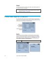
1
HYDRONIC MANOMETER MODEL HM685 OWNER’S MANUAL P/N 6006820, REVISION B JANUARY 2014 HYDRONIC MANOMETER MODEL HM685 OWNER’S MANUAL P/N 6006820, REVISION B JANUARY 2014 SHIP TO/MAIL TO: TSI Incorporated 500 Cardigan Road Shoreview, MN 55126-3996 USA U.S. Technical Support: (800) 874-2811/(651) 490-2811 Fax: (651) 490-3824 E-mail address: [email protected] Website: http://www.tsi.com INTERNATIONAL Technical Support: (001 651) 490-2811 Fax: (001 651) 490-3824 Manual History The following is a manual history of the Hydronic Manometer Model HM685 Owner’s Manual (P/N 6006820). ii Revision Date A B May 2013 January 2014 Hydronic Manometer Model HM685 Warranty Part Number Copyright Address Fax No. E-mail Address Limitation of Warranty and Liability (effective June 2011) 6006820 / Revision B / January 2014 ©TSI Incorporated / 2013–2014 / All rights reserved. TSI Incorporated / 500 Cardigan Road / Shoreview, MN 55126 / USA 651-490-3824 [email protected] (For country-specific terms and conditions outside of the USA, please visit www.tsi.com.) Seller warrants the goods sold hereunder, under normal use and service as described in the operator's manual, shall be free from defects in workmanship and material for twenty-four (24) months, or if less, the length of time specified in the operator's manual, from the date of shipment to the customer. This warranty period is inclusive of any statutory warranty. This limited warranty is subject to the following exclusions and exceptions: a. Hot-wire or hot-film sensors used with research anemometers, and certain other components when indicated in specifications, are warranted for 90 days from the date of shipment; b. Pumps are warranted for one year or 3000 hours; whichever comes first; c. Parts repaired or replaced as a result of repair services are warranted to be free from defects in workmanship and material, under normal use, for 90 days from the date of shipment; d. Seller does not provide any warranty on finished goods manufactured by others or on any fuses, batteries or other consumable materials. Only the original manufacturer's warranty applies; e. Unless specifically authorized in a separate writing by Seller, Seller makes no warranty with respect to, and shall have no liability in connection with, goods which are incorporated into other products or equipment, or which are modified by any person other than Seller. The foregoing is IN LIEU OF all other warranties and is subject to the LIMITATIONS stated herein. NO OTHER EXPRESS OR IMPLIED WARRANTY OF FITNESS FOR PARTICULAR PURPOSE OR MERCHANTABILITY IS MADE. WITH RESPECT TO SELLER’S BREACH OF THE IMPLIED WARRANTY AGAINST INFRINGEMENT, SAID WARRANTY IS LIMITED TO CLAIMS OF DIRECT INFRINGEMENT AND EXCLUDES CLAIMS OF CONTRIBUTORY OR INDUCED INFRINGEMENTS. BUYER’S EXCLUSIVE REMEDY SHALL BE THE RETURN OF THE PURCHASE PRICE DISCOUNTED FOR REASONABLE WEAR AND TEAR OR AT SELLER’S OPTION REPLACEMENT OF THE GOODS WITH NON-INFRINGING GOODS. TO THE EXTENT PERMITTED BY LAW, THE EXCLUSIVE REMEDY OF THE USER OR BUYER, AND THE LIMIT OF SELLER'S LIABILITY FOR ANY AND ALL LOSSES, INJURIES, OR DAMAGES CONCERNING THE GOODS (INCLUDING CLAIMS BASED ON CONTRACT, NEGLIGENCE, TORT, STRICT LIABILITY OR OTHERWISE) SHALL BE THE RETURN OF GOODS TO SELLER AND THE REFUND OF THE PURCHASE PRICE, OR, AT THE OPTION OF SELLER, THE REPAIR OR REPLACEMENT OF THE GOODS. IN THE CASE OF SOFTWARE, SELLER WILL REPAIR OR REPLACE DEFECTIVE SOFTWARE OR IF UNABLE TO DO SO, WILL REFUND THE PURCHASE PRICE OF THE SOFTWARE. IN NO EVENT SHALL SELLER BE LIABLE FOR LOST PROFITS OR ANY SPECIAL, CONSEQUENTIAL OR INCIDENTAL DAMAGES. SELLER SHALL NOT BE RESPONSIBLE FOR INSTALLATION, DISMANTLING OR REINSTALLATION iii COSTS OR CHARGES. No Action, regardless of form, may be brought against Seller more than 12 months after a cause of action has accrued. The goods returned under warranty to Seller's factory shall be at Buyer's risk of loss, and will be returned, if at all, at Seller's risk of loss. Buyer and all users are deemed to have accepted this LIMITATION OF WARRANTY AND LIABILITY, which contains the complete and exclusive limited warranty of Seller. This LIMITATION OF WARRANTY AND LIABILITY may not be amended, modified or its terms waived, except by writing signed by an Officer of Seller. Trademarks CompuDat is a trademark of TSI Incorporated. TSI and the TSI logo are registered trademark of TSI Incorporated. Microsoft, Excel, Windows, and Vista are registered trademarks of Microsoft Corporation. iv Hydronic Manometer Model HM685 Contents Manual History ............................................................................................ ii Warranty ..................................................................................................... iii About This Manual .................................................................................... ix Formatting and Typography .................................................................. ix Technical Assistance—Help! ................................................................ ix Safety Information ..................................................................................... xi Labels .................................................................................................... xi Description of Caution/Warning Symbols ............................................ xii Caution.............................................................................................. xii Warning............................................................................................. xii Caution or Warning Symbols ............................................................ xii CHAPTER 1 Introduction ........................................................................1-1 Instrument Description ........................................................................1-2 Unpacking ...........................................................................................1-3 CHAPTER 2 Getting Started ...................................................................2-1 Keypad ................................................................................................2-1 Powering the Instrument .....................................................................2-2 Using the AC Adapter ......................................................................2-2 Battery Installation ...........................................................................2-2 Battery Charging ..............................................................................2-4 Instrument Start-up .............................................................................2-5 Zeroing the Manometer .......................................................................2-5 Zeroing the Gauge Pressure Sensor ...............................................2-5 Zeroing the Differential Pressure Sensor ........................................2-6 Connecting the Manometer to the Test Points....................................2-7 Attaching the Hoses to the Manometer ...........................................2-7 Bleeding the Entrained Air ...............................................................2-7 Attaching the Hoses to the Test Points ...........................................2-8 Performing Pressure Measurements ..................................................2-8 Accessing the Pressure Measurement Screen ...............................2-8 Pressure Measurement Screen .......................................................2-9 Continuous Pressure Measurements ..............................................2-9 Discrete Pressure Measurements ...................................................2-9 Performing Flow Measurements .......................................................2-10 Accessing the Flow Measurement Screen ....................................2-10 Flow Measurement Screen ............................................................2-10 Continuous Flow Measurements ...................................................2-11 Discrete Flow Measurements ........................................................2-11 Performing Temperature Measurements ..........................................2-11 Connecting the Temperature Probe ..............................................2-11 v Setting Units of Measure ...................................................................2-12 Storing Discrete Measurements........................................................2-12 Disconnecting the Manometer from the Test Points .........................2-13 CHAPTER 3 Main Menu...........................................................................3-1 Zero Gauge Pressure..........................................................................3-1 Flow Setup ..........................................................................................3-2 Select Cv/Kv Factor .........................................................................3-2 Select Factor Type ...........................................................................3-3 Enter Cv/Kv Value ...........................................................................3-3 Edit Cv/Kv Name .............................................................................3-4 Select Fluid ......................................................................................3-5 CHAPTER 4 Data Logging ......................................................................4-1 Menu ...................................................................................................4-1 Log Mode ............................................................................................4-1 Log Settings ........................................................................................4-2 Choose Test ....................................................................................4-3 Name Test ...........................................................................................4-3 View Data ............................................................................................4-4 Choose Test ....................................................................................4-4 View Stats ........................................................................................4-4 View Samples ..................................................................................4-4 Delete Data .........................................................................................4-5 % Memory ...........................................................................................4-6 CHAPTER 5 Calculations Menu .............................................................5-1 Brake Power ........................................................................................5-1 Inputs ...............................................................................................5-2 Heat Flow ............................................................................................5-4 Inputs ...............................................................................................5-4 Calculating Cv/Kv ................................................................................5-6 Inputs ...............................................................................................5-7 Output ..............................................................................................5-8 Pump Law Impeller Diameter ..............................................................5-8 Inputs ...............................................................................................5-8 Output ..............................................................................................5-9 Pump Law Delta P ............................................................................5-10 Inputs .............................................................................................5-10 Output ............................................................................................5-11 Pump Law Brake Power....................................................................5-12 Inputs .............................................................................................5-12 Output ............................................................................................5-13 CHAPTER 6 Settings Menu.....................................................................6-1 Beeper .................................................................................................6-2 Select Units .........................................................................................6-2 Differential Pressure and Gauge Pressure .........................................6-3 Flow .....................................................................................................6-3 Temperature ........................................................................................6-4 Time Constant .....................................................................................6-4 Contrast ...............................................................................................6-5 vi Hydronic Manometer Model HM685 Set Time ..............................................................................................6-5 Set Date ..............................................................................................6-6 Time Format ........................................................................................6-6 Date Format ........................................................................................6-7 Number Format ...................................................................................6-7 Backlight ..............................................................................................6-8 Auto Off ...............................................................................................6-8 CHAPTER 7 Calibration ..........................................................................7-1 Calibration Differential Pressure and Calibration Gauge Pressure.....7-2 Calibration Temperature 1 and 2. .......................................................7-3 Restore Factory Calibration ................................................................7-3 CHAPTER 8 Maintenance and Troubleshooting ..................................8-1 Routine Maintenance ..........................................................................8-1 Draining the Hoses ..........................................................................8-1 Draining the Manometer Valve ........................................................8-1 In-Line Flow Restrictor .....................................................................8-2 Cleaning the In-line Flow Restrictors ...............................................8-2 Cleaning the Instrument Housing ....................................................8-2 Calibration ...........................................................................................8-3 Troubleshooting ..................................................................................8-3 Technical Contacts..............................................................................8-5 CHAPTER 9 USB Downloading to a Computer ....................................9-1 Installing the USB Software ................................................................9-1 Connecting the Manometer to the Computer ......................................9-2 First Time Connection......................................................................9-2 Software Interface ...............................................................................9-6 HM685 Data Download Steps .........................................................9-7 HM680 Download Instructions .........................................................9-9 Downloading Data .............................................................................9-10 APPENDIX A Specifications .................................................................. A-1 APPENDIX B Compliance ...................................................................... B-1 Contents vii (This page intentionally left blank) viii Hydronic Manometer Model HM685 About This Manual This manual explains how to set up, operate, and maintain the TSI® Hydronic Manometer Model HM685. Please read it thoroughly before using the instrument. Formatting and Typography Step-by-step instructions are numbered: 1, 2, 3, etc., set flush-left against the inside margin. References to keys on the manometer and the instrument's displayed readout are represented in bold typeface. In addition to the different typeface, displayed messages appear in quotes. Technical Assistance—Help! For technical assistance or questions about the instrument or this manual, or if the HM685 Hydronic Manometer needs repair or recalibration, call Technical Support at (651) 490-2811 or (800) 874-2811. ix (This page intentionally left blank) x Hydronic Manometer Model HM685 Safety Information Carefully read each of the following safety warnings prior to using the HM685 Hydronic Manometer. This section gives instructions to promote safe and proper handling of the HM658 Hydronic Manometer. IMPORTANT There are no user-serviceable parts inside the instrument. Refer all repair and maintenance to a qualified factory-authorized technician. All maintenance and repair information in this manual is included for use by a qualified factory-authorized technician. Labels Identification and calibration labels are attached to the outside of the hydronic manometer housing. 1. Serial number label (back panel) ) 2. Calibration label (back panel) 3. European symbol for non-disposable item. Item must be recycled. xi Description of Caution/Warning Symbols Appropriate caution/warning statements are used throughout the manual and on the instrument that require you to take cautionary measures when working with the instrument. Caution C a u t i o n Failure to follow the procedures prescribed in this manual might result in irreparable equipment damage. Important information about the operation and maintenance of this instrument is included in this manual. Warning W A R N I N G Warning means that unsafe use of the instrument could result in serious injury to you or cause damage to the instrument. Follow the procedures prescribed. Caution or Warning Symbols The following symbols may accompany cautions and warnings to indicate the nature and consequences of hazards: Warns that uninsulated voltage within the instrument may have sufficient magnitude to cause electric shock. Therefore, it is dangerous to make contact with any part inside the instrument. Warns that the instrument is susceptible to electro-static dissipation (ESD) and ESD protection procedures should be followed to avoid damage. Indicates the connector is connected to earth ground and cabinet ground. Carefully read each of the following safety warnings prior to using the HM685 Hydronic Manometer. W A R N I N G Never use the HM685 Hydronic Manometer or accessories on potable water systems or other systems which may be used to convey fluids for human or animal consumption. W A R N I N G Never charge non-rechargeable batteries by setting battery-type selection switch to NiMH when using alkaline or other non-rechargeable batteries. Fire, explosions, or other hazards may result. xii Hydronic Manometer Model HM685 C a u t i o n Never use the HM685 Hydronic Manometer to measure the pressure of volatile, flammable, or otherwise hazardous fluids or gasses. The instrument is not designed to be intrinsically safe, nor is it designed for use with caustic or corrosive chemicals. C a u t i o n Never connect the HM685 Hydronic Manometer or accessories to systems which exceed the instrument’s maximum pressure specification (300 psi; 2068 kPa). C a u t i o n Observe proper safety precautions and wear appropriate personal protective equipment, including gloves and eyewear, when working on high pressure or high temperature systems. Ruptured or leaking lines pose a potential risk of serious personal injury. C a u t i o n When using the HM685 Hydronic Manometer, verify all hose connections are secure prior to taking pressure measurements. Loose connections may result in the discharge of pressurized water or air, posing a potential risk of serious personal injury. C a u t i o n Exercise caution when disconnecting the HM685 Hydronic Manometer from a pressurized system. Water or air discharged under pressure poses a potential risk of severe injury. C a u t i o n Exercise caution in using the HM685 Hydronic Manometer near electrical equipment. Water spray associated with purging or disconnecting hoses presents a potential risk of damage to such equipment. C a u t i o n Thoroughly drain and dry the HM685 Hydronic Manometer hoses and internal piping after each use. This will help in limiting the potential for growth of hazardous microorganisms. C a u t i o n Never plug into the instrument any power supply other than the one provided with the instrument. C a u t i o n Always make certain that the battery switch is in the correct position for the type of battery being used (Alkaline/NiMH). Failure to do so may result in Fire, Explosions or other hazard. xiii C a u t i o n Never use Alkaline and NiMH batteries together on the same instrument. C a u t i o n Always use the hoses with the provided Flow Restrictor connected in line with the shut-off valves to prevent “Water Hammer.” Water Hammer is a fast moving shock wave of pressure caused by sudden changes in the system such as a valve being opened or closed or a pump being turned on or off. xiv Hydronic Manometer Model HM685 CHAPTER 1 Introduction The HM685 Hydronic Manometer is an easy-to-use instrument designed for the accurate measurement of pressure and calculation of flow in nonpotable water and air systems. Features of the manometer include the following: Single-function keys for ease of use Simultaneous measurement and display of High-side gauge and Differential pressure Direct calculation and display of Low-side gauge pressure Direct calculation and display of flow Data logging with calculated statistics Output port for downloading stored data to a computer User-selectable units of measure User-selectable time constant Easy-to-read, LCD with backlight Power supplied via AC adapter or batteries (alkaline or rechargeable NiMH) Internal NiMH battery charging Automatic power shutoff Splash-proof case Rugged carrying case for storage of meter, hoses, accessories, tools, and paperwork Two Temperature ports for simultaneous low and high side temperature measurements 1-1 Instrument Description The HM685 Hydronic Manometer includes: Meter 4-inch temperature probe Hard carrying case (2) 6-foot (1.8 m) hoses with shut-off valves & filters (2) P/T gauge adapter probes (2) B&G readout probes Keypad (2) ¼” Flare male × ¼” male NPT fittings (2) Female ¼” NPT to Male ¼” ISO Parallel Pipe Threads (2) Female ¼” NPT to Male ¼” ISO Tapered Pipe Threads AC adapter (4) NiMH batteries Carrying strap Owner’s manual NIST traceable certificate Valve Handle LCD Display Neck/Hanging Strap Clips Bottom Port Cover Pressure Ports AC Power Adapter Input Port USB Port Temperature Probe Port 2 Temperature Probe Port 1 Figure 1-1 HM685 Meter Description 1-2 Hydronic Manometer Model HM685 Unpacking As unpacking the instrument and accessories, check the components against the packing list. If any parts are missing or damaged, notify TSI immediately. Tables 1-1 and 1-2 list standard and optional components for the HM685 Hydronic Manometer. Table 1-1 Standard Components Item 4 in. (10 cm) long, 0.125 in. (3.175 mm) dia. Temperature probe Carrying case Blue and red hose kit with shut-off valves and flow restrictor P/T gauge adapter probes (2) B&G readout probes (2) AC adapter 4 AA-size NiMH battery Battery holder Carrying strap Owner’s manual USB Cable CompuDat CD Pocket screw driver Part No. 801290 1319409 6006813 632360004 632360010 6004983 1208048 1801206 2913011 6006820 1303754 1083575 3012054 Table 1-2 Optional Components Item Accessory fittings kit (USA only) 4 in. (10 cm) long, 0.125 in. (3.175 mm) dia. Temperature probe External battery charger with (4) AA NiMH batteries (USA only) Part No. HMFIT 801290 801093 Please register your HM685 promptly through our website at http://register.tsi.com. Registration of your product allows us to notify you of product updates. Introduction 1-3 (This page intentionally left blank) 1-4 Hydronic Manometer Model HM685 CHAPTER 2 G e t t i n g S ta r t e d Keypad Each key and its function are described below. ▲▼ The ▲and ▼keys are used to navigate through menus or to select an item to change. When entering text, these keys change the highlighted letter/number. ◄► The ◄ and ► keys are used to change the selected item. When entering text, these keys move the cursor to the desired location in a left/right or up/down direction. ESC The ESC key returns to the previous screen or to cancel an operation without saving changes. The ENTER key selects a menu item or accepts changes made within a menu item and returns to the previous screen. From either the Pressure or Flow Measurement screens, pressing the ENTER key accesses the Main Menu. READ Pressing the READ key initiates taking a time-averaged reading based on Log Mode and Log Settings. After taking the reading, the values are stored to memory (current Test ID) and displayed on screen for a period of four (4) seconds or until the READ key has been pressed again. The READ key also updates the calculations with current readings in the CALCULATIONS Menu. See Chapter 4 for more details on Data Logging and adjusting the log mode, sample interval and log settings. Press the BACKLIGHT key to turn the display’s backlighting on or off. Note: Backlighting has a significant impact on battery life. Use backlighting only when working in areas where you cannot read the display with existing light. DATA Press the DATA key from either the Pressure or Flow Measurement screens to access the Data Logging Menu. PRESS Press the PRESS key from the Flow Measurement screen to access the Pressure Measurement screen. Press the key to turn the HM685 Hydronic Manometer on or off. CALC Pressing the CALC key from either the Pressure or Flow Measurement screens provides access to the Calculations Menu. FLOW Pressing the FLOW key from the Pressure Measurement screen provides access to the Flow Measurement screen. 2-1 Powering the Instrument The HM685 Hydronic Manometer is equipped to power either by four (4) AA-size batteries (alkaline or rechargeable NiMH) or the AC adapter. Using the AC Adapter The AC adapter allows the HM685 Hydronic Manometer to power from a standard AC wall outlet. When using the AC adapter, the batteries (if installed) are bypassed. The AC adapter also charges the NiMH type batteries (if installed) in the unit. Note: With the battery-type selection switch set to NiMH, the manometer will initiate charging the batteries whenever the AC adapter is connected. C a u t i o n Only use TSI P/N 6004983, the AC adapter supplied with the instrument, when powering the HM685 Hydronic Manometer externally. Do not connect the AC adapter or car adapter provided with the battery optional charger (801093) or any other AC adapter to the HM675/685. Using any other power cable or power supply may cause damage to the device and void the warranty. WARNING Never charge non-rechargeable batteries by setting battery-type selection switch to NiMH with alkaline or other non-rechargeable batteries. Fire, explosions, or other hazards may result. C a u t i o n Never plug into the instrument any power supply other than the one provided with the instrument. Battery Installation To install/replace the batteries: 1. Turn the manometer off and locate the battery cover on the back of the unit. 2. Loosen the screw on the battery compartment cover and lift to remove. 3. Remove the battery holder. Tapping the backside of the meter against your hand may assist in removing the battery holder. 4. Remove the old batteries and replace with fresh batteries (alkaline or rechargeable NiMH). Ensure that the batteries are correctly oriented within the battery holder. 2-2 Hydronic Manometer Model HM685 5. Set the battery-type selection switch to indicate the type of batteries to be used (alkaline or rechargeable NiMH). Battery Type Selection Switch Figure 2-1 Location of Battery-Type Selection Switch WARNING Do not use Lithium batteries in this instrument. Fire, explosions, or other hazards may result. C a u t i o n Never use Alkaline and NiMH batteries together on the same instrument. C a u t i o n Always make certain that the battery switch is in the correct position for the type of battery being used (Alkaline/NiMH). Failure to do so may result in Fire, Explosions, or other hazard. 6. Reinstall the battery holder. Ensure the battery holder orientation is such that its terminals make contact with the spring contacts within the battery compartment. 7. Replace the battery compartment cover. Getting Started 2-3 Notes: The NiMH batteries included with the instrument may require recharging prior to first use. Fully charged batteries should enable the instrument to operate for a period of at least twelve (12) hours Setting the battery-type selection switch properly will prevent unwanted charging of non-rechargeable alkaline batteries and provide charging of NiMH batteries when the AC adapter is connected. A battery charge life remaining indicator is shown on the display whenever the manometer is powered by batteries, and turned on. When using NiMH batteries, the indicator of battery charge life remaining will not be accurate due to their inherent non-linear voltage drop with power use. Due to the danger of battery leakage, remove batteries from the battery compartment prior to storage. Never mix battery types. For maximum battery life, ensure backlight is “off” when not needed. Battery Charging WARNING Do not use Lithium batteries in this instrument. Fire, explosions, or other hazards may result. C a u t i o n Never plug into the instrument any power supply other than the one provided with the instrument. C a u t i o n Always make certain that the battery switch is in the correct position for the type of battery being used (Alkaline/NiMH). Failure to do so may result in Fire, Explosions or other hazard. C a u t i o n Never use Alkaline and NiMH batteries together on the same instrument. The HM685 Hydronic Manometer allows for internal charging of AA-size type NiMH (only) batteries. Charging of the batteries is initiated as follows: 1. Turn the manometer off and locate the battery cover on the back of the unit. 2. Loosen the screw on the battery compartment cover and lift to remove. 3. Remove the battery holder. Tapping the backside of the meter against your hand may help in removing the battery holder. 4. Verify the batteries installed are rechargeable type NiMH. 5. Set the battery-type selection switch to NiMH. 2-4 Hydronic Manometer Model HM685 6. Reinstall the battery holder. Ensure the battery holder orientation is such that its terminals make contact with the spring contacts within the battery compartment. 7. Replace the battery compartment cover. 8. Plug in the AC adapter. Notes: Full charge of the batteries is achieved within four (4) hours. Fully charged batteries should enable the instrument to operate for a period of at least twelve (12) hours. The manometer is fully operational while charging batteries. Never attempt to charge battery types other than AA-size rechargeable NiMH. For maximum battery life, ensure the backlight is “off” when not needed. Never mix battery types. NiMH batteries should only be charged at room temperature. Starting with batteries that are too cold or too warm can cause the charge cycle to terminate early. Instrument Start-up Upon turning the HM685 Hydronic Manometer on, the meter engages in a brief self-check while displaying the serial number, model number, and revision of the instrument being used. While completing the self-check, the user is given the option to zero the gauge pressure sensor or skip the zero process prior to proceeding to the Pressure Measurement Screen. Zeroing the Manometer The HM685 Hydronic Manometer is equipped with both a gauge and differential pressure sensor, allowing for simultaneous measurement and display of High-side gauge and Differential pressure. The gauge and differential pressure sensors are zeroed independently of one another. Zeroing the Gauge Pressure Sensor To ensure the most accurate gauge pressure (High P) measurements, the HM685 gauge pressure sensor should be zeroed prior to taking readings on each new system. When not in the instrument start-up sequence, the gauge pressure sensor is zeroed as follows: 1. Enter the Main Menu by pressing the ENTER ( ) key. 2. Select Zero Gauge Pressure. Getting Started 2-5 3. Follow the on-screen instruction to complete the gauge pressure sensor zeroing process. 4. Allow the manometer to stand undisturbed for five (5) seconds until the zero gauge pressure sensor function has completed. Notes: Zeroing the gauge pressure sensor requires the user to disconnect the High pressure (red) hose; as such it is often most convenient to zero the gauge pressure sensor as part of the start-up sequence (i.e., before hoses have been connected). The zero offset of the gauge pressure sensor is sensitive to temperature changes. If moving the manometer between areas of extreme temperature difference, it is best to allow the meter to settle to the new temperature prior to zeroing. Zeroing the Differential Pressure Sensor To ensure the most accurate differential pressure (dP) measurements and calculated flow (Flow) values, the HM685 differential pressure sensor should be zeroed prior to taking readings on each new system. The differential pressure sensor is zeroed as follows: 1. Go to the Measurement Screen. 2. Turn the valve handle on the manometer to the BYPASS position. 3. The instrument will automatically zero the differential pressure sensor. Follow the on-screen instructions and return the knob to MEASURE once this is done. Notes: Any pressures applied to the hoses will not affect the dP zeroing function. This feature allows for successful zeroing of the differential pressure sensor while maintaining connections to the system under test. 2-6 Zeroing of the differential pressure sensor is initiated any time the valve handle has been turned to the BYPASS position while in the Pressure or Flow Measurement screens. This feature allows for successful zeroing of the differential pressure sensor while entrained air is being purged from the hoses. The zero offset of the differential pressure sensor is sensitive to temperature changes. If moving the manometer between areas with extreme temperature difference, it is best to allow the meter to settle to the new temperature prior to zeroing. Hydronic Manometer Model HM685 Connecting the Manometer to the Test Points Attaching the Hoses to the Manometer 1. Connect the straight female flare fitting on the High pressure (red) hose to the male fitting on the top of the manometer marked with a plus (+) sign. 2. Connect the straight female flare fitting on the Low pressure (blue) hose to the male fitting on the top of the manometer marked with a minus(-) sign. Bleeding the Entrained Air To ensure the most accurate pressure measurements, all entrained air within the hoses should be purged as follows: 1. Turn the shut-off ball valve on both the High and Low pressure hoses to the closed position. 2. Turn the valve handle on the manometer to the MEASURE position. 3. Using an appropriate fitting, connect the open end of the High pressure (red) hose to the test point with the higher line pressure. 4. Attach the appropriate fitting to the open end of the Low pressure (blue) hose. 5. To ensure all the air is bled from the hoses, hold the open end of the Low pressure (blue) hose in an upright position over a suitable receptacle or near a drain. 6. Turn the shut-off ball valve on both the High and Low pressure hoses to the open position. 7. Turn the valve handle on the manometer to the BYPASS position to allow the liquid flow to displace the entrained air. Note: Zeroing of the differential pressure sensor is initiated any time the valve handle has been turned to the BYPASS position while in the Pressure or Flow Measurement screens. This feature allows for successful zeroing of the differential pressure sensor while entrained air is being purged from the hoses. 8. Once the liquid is flowing steadily from the Low pressure (blue) hose, turn the valve handle on the manometer to the MEASURE position. Note: The time to fully prime the hose with fluid may take up to one minute depending on the line pressure. Higher line pressure will reduce the bleed time. Getting Started 2-7 Attaching the Hoses to the Test Points 1. As indicated previously, use an appropriate fitting to connect the open end of the High pressure (red) hose to the test point with the higher line pressure. 2. Using an appropriate fitting, connect the open end of the Low pressure (blue) hose to the test point with the lower line pressure. Note: If the hoses are connected in the inverse orientation (i.e., High pressure (red) hose to the lower line pressure), the displayed Highside gauge pressure (High P) will be less than the Low-side gauge pressure (Low P), and the Differential pressure (dP) and resulting calculated flow (Flow) will be negative. Performing Pressure Measurements The HM685 Hydronic Manometer allows for simultaneous measurement and display of the High-side gauge and Differential pressure. The calculated Low-side gauge pressure is also displayed. While in the Pressure Measurement screen, the manometer makes and displays continuous pressure measurements, and allows for data storage to the memory. Accessing the Pressure Measurement Screen The Pressure Measurement screen is accessed by pressing the PRESS key from the Flow Measurement screen, or by pressing the ESC key from any of the primary menus (Main Menu, Data Logging Menu, and Calculations Menu) when that menu was accessed from the Pressure Measurement screen. 2-8 Hydronic Manometer Model HM685 Pressure Measurement Screen *Shown with two optional accessory temperature probes attached. High-Side Gauge Pressure The High-side gauge pressure measurement is indicated as High on the manometer display. Low-Side Gauge Pressure The Low-side gauge pressure reading is indicated as Low on the manometer display. It represents a calculated value determined from the measured High-side gauge and Differential pressure as follows: Low P = High P – dP Differential Pressure The Differential pressure measurement is indicated as dP on the manometer display. Continuous Pressure Measurements The HM685 Hydronic Manometer continuously measures and displays pressure readings whenever the manometer is in the Pressure Measurement or Flow Measurement screen, with the exception of when the READ key is pressed. When the READ key is pressed, the displayed readings are averaged measurements taken over the sampling period as defined by the Log Mode and Log Settings. The display is updated once per second. Discrete Pressure Measurements Taking a discrete pressure measurement allows for measurement and display of a single time-averaged reading taken over the sampling period as defined by the Log Mode and Log Settings. Discrete pressure measurement values are displayed on-screen for a period of 4 seconds and then returns to continuous measurement mode. See Chapter 4, Data Logging, for more details on setup. 1. Press the READ key. 2. Allow the manometer to stand undisturbed until the reading is complete. Getting Started 2-9 Performing Flow Measurements The HM685 Hydronic Manometer allows for continuous calculation and display of flow. While in the Flow Measurement screen, the manometer makes and displays continuous pressure measurements, calculates and displays continuous flow readings, and allows for discrete data storage to the memory. Note: The Cv (Kv) value of the measured valve must be known in order to obtain meaningful flow readings. Accessing the Flow Measurement Screen The Flow Measurement screen is accessed by pressing the FLOW key from the Pressure Measurement screen. Flow Measurement Screen *Shown with the accessory temperature probe disconnected. 2-10 Flow The flow reading is indicated as Flow on the manometer display. It represents a calculated value determined from the measured Differential pressure and user entered values for the valve flow coefficient (Cv or Kv) and fluid specific gravity. Cv/Kv The valve flow coefficient is indicated as Cv (Kv) on the manometer display. Notes: The Cv (Kv) value of the measured valve must be known in order to obtain meaningful flow readings. 100 different Cv (Kv) names and values can be stored in the instrument (Reference Chapter 3, Flow Setup). Hydronic Manometer Model HM685 Continuous Flow Measurements The HM685 Hydronic Manometer continuously measures and displays flow readings whenever the manometer is in the Flow Measurement screen, with the exception of when the READ key is pressed. When the READ key is pressed, the displayed readings are averaged measurements taken over the sampling period as defined by the Log Mode and Log Settings. The display is updated once per second. See Chapter 4, Data Logging, for more details on setup. Discrete Flow Measurements Taking a flow measurement allows for measurement and display of a single time-averaged reading taken over the sampling period as defined by the Log Mode and Log Settings. Discrete pressure or flow measurement values are displayed on-screen for a period of 4 seconds and then returns to continuous measurement mode. See Chapter 4, Data Logging, for more details on setup. 1. Press the READ key. 2. Allow the manometer to stand undisturbed until the reading is complete. Performing Temperature Measurements The HM685 Hydronic Manometer accessory temperature probe is a 1/8” diameter, stainless steel sheathed immersion probe designed for measurement of water line temperatures. When using the accessory temperature probe, the HM685 Hydronic Manometer is equipped to make and display continuous temperature measurements in both the Pressure and Flow Measurement screens. Two temperature probes can be connected to the instrument to measure upstream and downstream temperature simultaneously. Connecting the Temperature Probe Connect the keyed 3-pin plug of the accessory temperature probe to the mating connector located on the right-hand side of the manometer. Note: A locking nut is provided on the accessory temperature probe plug to allow for a more secure attachment when connecting to the manometer. Getting Started 2-11 Setting Units of Measure The units of measure for gauge pressure, differential pressure, flow, and temperature are adjusted within the Setting Menu. See Chapter 6, Settings Menu for more details. Available unit settings are as follows: Gauge Pressure psi, inH2O, ftH2O, inHg, kPa, mH2O, mmHg, and bar Differential Pressure psi, inH2O, ftH2O, inHg, kPa, mH2O, mmHg, and bar Flow USGPM, UKGPM, l/s, l/m, m3/h Temperature °F or °C Storing Discrete Measurements Taking a discrete measurement allows for measurement, display, and storage of a single time-averaged reading taken over the sampling period. Discrete measurement values are stored to the memory (current Test ID) and displayed on-screen for a period of four (4) seconds. See Chapter 4, Data Logging for more details on data logging and adjusting the log mode, sample interval, and log settings. 1. Press the READ key (from the Pressure or Flow Measurement screen). 2. Allow the manometer to stand undisturbed until the reading is complete (time of completion is dependent on the time constant setting). Note: 2-12 Discrete measurements stored from the Pressure Measurement screen will not contain flow data. Hydronic Manometer Model HM685 Disconnecting the Manometer from the Test Points C a u t i o n Exercise caution when disconnecting the HM685 Hydronic Manometer from a pressurized system. Water or air discharged under pressure poses a potential risk of severe injury. C a u t i o n Exercise caution in using the HM685 Hydronic Manometer near electrical equipment. Water spray associated with purging or disconnecting hoses presents a potential risk of damage to such equipment. C a u t i o n Thoroughly drain and dry the HM685 Hydronic Manometer hoses and internal piping after each use. This will help in limiting the potential for growth of hazardous microorganisms. The following provides a guideline for disconnecting the manometer from the test points once measurements have been completed. 1. Turn the shut-off ball valve on both the High and Low pressure hoses to the closed position. 2. Disconnect the High pressure (red) hose from the higher line pressure test point. 3. Disconnect the Low pressure (blue) hose from the lower line pressure test point. Note: If additional measurements at another location/system containing the same fluid are to be made, it is not necessary to proceed to step 4 and drain the fluid entrained within the hoses at this time. The fluid remaining within the hoses will help minimize the time necessary to bleed entrained air prior to making subsequent measurements. 4. Place the open end of the Low pressure (blue) hose in a suitable receptacle or near a drain. 5. Turn the valve handle on the manometer to the BYPASS position. 6. Turn the shut-off ball valve on the Low pressure (blue) hose to the open position to discharge the pressurized fluid out of the open end of the Low pressure (blue) hose. 7. Elevate the High pressure (red) hose and turn its shut-off ball valve to the open position to allow for draining of the remaining entrained fluid. Getting Started 2-13 (This page intentionally left blank) 2-14 Hydronic Manometer Model HM685 CHAPTER 3 Main Menu The Main Menu is accessed by pressing the ENTER Pressure or Flow Measurement screens. key from either the Zero Gauge Pressure Zero Gauge Pressure zeros the manometer’s gauge pressure sensor. Refer to Zeroing the Manometer in the Getting Started chapter for instructions. 3-1 Flow Setup Use Flow Setup to set values for key factors that impact measured flow values. Select Cv/Kv Factor Allows input up to 100 valve flow coefficients (Cv/Kv factors) to calculate flow from differential pressure. These are typically coefficients provided by the balancing valve manufacturers and can be dependent on the type of valve and the valve setting in the case of variable valves. Within Flow Setup 100 user-programmed valve flow coefficients (Cv or Kv) that are stored within the instrument are selectable. The most recent selected Cv (Kv) factor is the default when entering the Flow Measurement screen. 3-2 Hydronic Manometer Model HM685 Select Factor Type Enter Cv/Kv Value A known Cv/Kv Value is required of the measured valve to obtain accurate flow readings. Main Menu 3-3 Edit Cv/Kv Name Up to 100 different Cv/Kv names and values can be stored. Edit the name of the selected Cv (Kv) factor. (continued on next page) 3-4 Hydronic Manometer Model HM685 Select Fluid Defines the fluid for the manometer to account for the fluid’s specific gravity when calculating flow. The fluid type of the system being measured is Water or Other. Water Select Water to automatically determine the specific gravity based upon the measured temperature of the fluid (Tprobe). Note: If the accessory temperature probe is not connected, the user will have the option of manually entering the fluid temperature (T-entered). Other Select Other to prompt for entry of the fluid’s specific gravity. Note: When Other is selected as the fluid type, the entered value for specific gravity will not be compensated with changes in temperature. Specific Gravity Main Menu 3-5 Entered Temperature 3-6 Hydronic Manometer Model HM685 CHAPTER 4 D a ta L o g g i n g Menu Access the Data Logging Menu by pressing the DATA key from either the Pressure or Flow Measurement screens or from the Main Menu. Log Mode The HM685 is programmable to store measurement to memory in the following logging formats: Auto-save Cont-key Cont-time 4-1 Auto-Save Logging In Auto-save mode, user samples are automatically logged to memory at the end of the sampling period. To start logging, press the Read key. Cont-.key Logging In Cont-key Logging mode, logging starts by press the Read key. The instrument continues logging until the Esc key is pressed. Cont.-time Logging In Cont-time mode, readings start by pressing the Read key. The instrument continues taking samples until the time set in “Sample Time” elapses or the Esc key is pressed. Log Settings Log Settings defines the frequency period with which the manometer will log sample readings. When the Log Mode is set to Cont-Time, this setting is also used to define the length of the test in hh:mm:ss. Note: 4-2 It is recommended that the logging interval must be set at a time period that is greater than or equal to the current setting of the time constant. Hydronic Manometer Model HM685 Choose Test Use the Choose Test screen to choose the Test where the samples (readings) will be stored. Name Test Name Test screen allows customizing the Test ID name of the selected test using 10 characters maximum. Use the arrow keys to move the cursor to a desired location, press Enter to accept. This feature can be used to logically name measurement locations for future analysis or report generation; e.g., Conference Room 1, Break Room, Machine Shop, etc. Data Logging 4-3 View Data The View Data screen allows users to choose the data they wish to review. Choose Test Select any of the 100 available Test IDs within the instrument. All new data stored is saved to the most recently selected Test ID. View Stats Displays statistics (average, minimum, and maximum) of a selected Test ID and the number of samples and date/time the samples were taken. AVG (average of all values stored in TEST ID.) MIN (lowest value stored in TEST ID) MAX (highest value stored in TEST ID) SUM (sum of all values stored in TEST ID) Note: SUM is only presented for flow readings. View Samples Displays the total number of readings to be stored as part of the continuous unattended data logging. Note: 4-4 The instrument can store a maximum of 4000 different samples. These samples can be distributed over one or all of the available Test IDs. Hydronic Manometer Model HM685 Delete Data Delete discrete samples, an entire Test ID, or all data stored to the instrument at this menu. Note: Deleted data cannot be retrieved. Delete All Delete all samples stored to the instrument, as well as restoring the factory set default names to each of the Test IDs. Delete Test Delete all samples within the current Test ID as well as restoring its factory set default name. Delete Sample Delete discrete samples within the current Test ID. The ▲and ▼keys toggle between the individual data samples. Note: Test ID statistics automatically recalculate upon deletion of an individual stored sample. Data Logging 4-5 % Memory % Memory displays the total memory available. Delete All, under Delete Data, clears memory and resets to 100 percent. 4-6 Hydronic Manometer Model HM685 CHAPTER 5 Calculations Menu The HM685 Hydronic Manometer is capable of performing a variety of calculations useful in evaluating hydronic system performance. The Calculations Menu is accessed by pressing the CALC key from either the Pressure or Flow Measurement screens. Brake Power This Calculations Menu option determines pump brake power. Press READ button to auto calculate differential pressure 5-1 Inputs The following inputs are necessary for calculating brake power. Use the ▲ and ▼ keys to select the parameter, and the ◄ and ► keys to change the value of the highlighted field. Units for the inputs are driven by what was last set in the Pressure and Flow Measurement screens. Flow The pump flow rate. dP The pressure drop measured across the pump. Note: The pressure drop across the pump can be entered as a real-time measurement. With the value for differential pressure highlighted, press the READ key. The field will begin updating with measured values of differential pressure. Press the READ key again to discontinue real-time updates. Press READ button to auto calculate differential pressure 5-2 Hydronic Manometer Model HM685 Efficiency The pump efficiency (as a percent). Notes: Power Units The pump efficiency should be provided by the manufacturer. If the pump efficiency is not known, allowing for an efficiency factor of 70 % is a good rule-of-thumb. The calculated pump brake power (BP) automatically updates as the input parameters are changed. Using the ▲ and ▼ keys to scroll, and the ◄ and ► keys to change the selected field, the unit of measure for brake power can be adjusted. Available units for brake power are: bhp, W, and kW. Calculations Menu 5-3 Heat Flow This Calculations Menu option allows for determination of heat flow. Upstream Temperature Press READ button to auto calculate T1 and T2 Downstream Temperature Inputs The following inputs are necessary for calculating heat flow. Use the ▲ and ▼ keys to select the parameter to be updated, and the ◄ and ► keys to change the value of the highlighted field. Units for the inputs are driven by what was last set in the Pressure and Flow Measurement screens (with the exception of specific heat). T1 T2 Flow 5-4 The upstream fluid temperature of the device being measured. Note: The upstream temperature can be entered as a real-time measurement if the accessory temperature probe is connected. With the value for the upstream temperature highlighted, press the READ key. The field will begin updating with measured values of temperature. Press the READ key again to discontinue real-time updates. The downstream fluid temperature of the device being measured. Note: The downstream temperature can be entered as a real-time measurement if the accessory temperature probe is connected. With the value for the downstream temperature highlighted, press the READ key. The field will begin updating with measured values of temperature. Press the READ key again to discontinue real-time updates. The flow rate through the device. Note: The flow rate through the device can be entered as a real-time measurement. With the value for flow highlighted, press the READ key. The field will begin updating with calculated values of flow. Press the READ key again to discontinue real-time updates. Hydronic Manometer Model HM685 Specific Heat The specific heat of the system fluid. Note: The unit of measure for specific heat is driven by that selected for heat flow as follows: Heat flow in Btu/hr → specific heat in Btu/lb°F Heat flow in W or kW → specific heat in kJ/kg°C The default specific heat is that of water: 1.00 Btu/lb°F (4.19 kJ/kg°C) Specific Gravity Calculations Menu 5-5 Heat Flow Units Heat Flow measurement can display in Btu/hr, W, or KW units. The calculated heat flow (HF) automatically updates as the input parameters are changed. Using the ▲ and ▼ keys to scroll, and the ◄ and ► keys to change the selected field, the unit of measure for heat flow can be adjusted. Available units for heat flow are: Btu/hr, W, and kW. Calculating Cv/Kv This Calculations Menu option allows for determination of a valve flow coefficient (Cv or Kv). Differential Pressure Flow Coefficient 5-6 Hydronic Manometer Model HM685 Inputs The following inputs are necessary for calculating the flow coefficient. Use the ▲ and ▼ keys to select the parameter to be updated, and the ◄ and ► keys to change the value of the highlighted field. Units for the inputs are driven by what was last set in the Pressure and Flow Measurement screens. Differential Pressure (dP) The pressure drop across the valve. Flow The flow rate through the valve. Specific Gravity The specific gravity of the system fluid. Calculations Menu 5-7 Output The calculated valve flow coefficient (Cv or Kv ) automatically updates as the input parameters are changed. Note: Whether a Cv or Kv value is being calculated is dependent on the type (Cv or Kv ) set for the current selected valve flow coefficient (Reference Chapter 3, Flow Setup). Pump Law Impeller Diameter This Calculations Menu option allows for determination of required pump impeller size. The calculation is based upon the following affinity law: Flow varies directly as the change in impeller diameter. Actual Flow Actual Impeller Diameter Desired Flow Required Impeller Diameter Inputs The following inputs are necessary for calculating the required impeller diameter. Use the ▲ and ▼ keys to select the parameter to be updated, and the ◄ and ► keys to change the value of the highlighted field. Units for the inputs are driven by what was last set in the Flow Measurement screen (with the exception of impeller diameter). Flow1 5-8 The actual system flow rate. Hydronic Manometer Model HM685 Diam1 The actual pump impeller diameter. Flow2 The desired system flow rate. Impeller Dia Units The impeller diameter in inches or millimeters. Output The calculated required impeller diameter (Diam2) to achieve the desired flow will automatically update as the input parameters are changed. Using the ▲ and ▼ keys to scroll, and the ◄ and ► keys to change the selected field, the unit of measure for impeller diameter may be adjusted. Available units for impeller diameter are: in, and mm. Calculations Menu 5-9 Pump Law Delta P This Calculations Menu option allows for determination of required pump pressure drop. The calculation is based upon the following affinity law: Pump pressure drop varies as the square of flow. Actual Flow Actual Differential Pressure Desired Flow Required Differential Pressure Inputs The following inputs are necessary for calculating the required pump pressure drop. Use the ▲ and ▼ keys to select the parameter to be updated, and the ◄ and ► keys to change the value of the highlighted field. Units for the inputs are driven by what was last set in the Pressure and Flow Measurement screens. Flow1 5-10 The actual system flow rate. Hydronic Manometer Model HM685 dP1 The actual pump pressure drop. Flow2 The desired system flow rate. Output The calculated required pump pressure drop (dP2) to achieve the desired flow will automatically update as the input parameters are changed. The units for pump pressure drop are driven by what was last set in the Pressure and Flow Measurement screens. Calculations Menu 5-11 Pump Law Brake Power This Calculations Menu option allows for determination of required pump brake power. The calculation is based upon the following affinity law: Pump brake power varies as the cube of flow. Actual Flow Actual Pump Brake Power Desired Flow Required Pump Brake Power Inputs The following inputs are necessary for calculating the required pump brake power. Use the ▲ and ▼ keys to select the parameter to be updated, and the ◄ and ► keys to change the value of the highlighted field. Units for the inputs are driven by what was last set in the Pressure and Flow Measurement screens (with the exception of brake power). Flow1 5-12 The actual system flow rate. Hydronic Manometer Model HM685 BP1 The actual pump brake power. Flow2 The desired system flow rate. Output The calculated required pump brake power (BP2) to achieve the desired flow will automatically update as the input parameters are changed. Using the ▲ and ▼ keys to scroll, and the ◄ and ► keys to change the selected field, the unit of measure for pump brake power may be adjusted. Available units for pump brake power are: bhp, W and kW. Calculations Menu 5-13 (This page intentionally left blank) 5-14 Hydronic Manometer Model HM685 CHAPTER 6 Settings Menu The Settings menu allows customization of the instrument display. General settings include: Beeper Select Units Differential Pressure and Gauge Pressure Flow Temperature Time Constant Contrast Set Time Set Date Time Format Date Format Number Format Backlight Auto Off Navigate to the Settings menu by pressing the Enter key at the Pressure or Flow display. Use the arrow keys to select an option or to change the settings for each option. Press the Enter key to accept the selected setting. 6-1 Beeper The Beeper setting changes the keypad press with an audible beep or silent. Enable sets an audible beep Disable provides no audible beep Select Units Select Units adjusts the format of the delimiter in both displayed and stored data for differential pressure, gauge pressure, flow, and temperature. 6-2 Hydronic Manometer Model HM685 Differential Pressure and Gauge Pressure Highlight either differential pressure or gauge pressure and press the Enter key. Use the arrow keys to highlight the appropriate measurement and press the Enter key to accept. Flow At the Select Units screen, highlight Flow and press the Enter key. Highlight the appropriate measurement and press the Enter key to accept. Settings Menu 6-3 Temperature Temperature readings can display in °C or °F. At the Select Units menu, highlight Temperature and press the Enter key to select the desired setting. Time Constant The current value of the time constant is adjustable. Available settings include 1, 5, 10, 20, and 30 seconds. Notes: The time constant is the period over which the manometer averages measurements. Example: with the time constant equal to ten (10) seconds, the displayed reading represents the average of measurements taken over the previous ten (10) seconds. Increasing the time constant will serve to improve measurement stability, particularly when measuring systems with fluctuating pressures. 6-4 Hydronic Manometer Model HM685 Contrast The Contrast menu allows contrast adjustment to the manometer display based on the surrounding lighting environment. Setting selections range from 0 to 10. The higher the settings number, the darker the contrast of the display. Use the up and down or left and right arrow keys to adjust contrast. Set Time The Set Time menu sets the instrument’s real-time clock. The digit selected to change will flash. Use the arrow keys to select the hour/minute digits and to adjust accordingly. Press the Enter key to confirm. The time format of 12 or 24 hour is set at the Time Format menu. Settings Menu 6-5 Set Date The date is programmed to the instrument at the Set Date menu. The digit selected to change will flash. Use the arrow keys to select the date, month, or year and to adjust the date accordingly. Press the Enter key to confirm. Time Format The time format displays the time in a 12 or 24 hour format. 6-6 Hydronic Manometer Model HM685 Date Format Three date settings are selectable based on user preference and include: Month/Date/Year Date/Month/Year Year/Month Date Number Format Settings Menu 6-7 Backlight The Backlight feature illuminates the display in low light conditions. Backlight options include: Auto (automatically turns on backlight in low-light condition) Disable (no backlighting) Enable (backlight is always on) Auto Off Automatic shutoff extends battery life by turning off the instrument if the keypad is inactive for a period of thirty (30) minutes. Shutoff options include: Disable (instrument does not power off after inactivity) Enable (instrument powers off after 30 minute inactivity) Note: 6-8 The automatic shutoff feature is disabled whenever data logging is active. Hydronic Manometer Model HM685 CHAPTER 7 Calibration On the calibration screen, the user can either adjust the factory calibration value so their measurements meet another standard or can restore factory calibration settings to the instrument in case they believe the calibration of the instrument has changed. The following items can be seen in each section of the calibration screen. 1. The magnitude of user adjustment 2. The factory calibrated measurement value 3. The measurement value after performing the user adjustment. This allows the user to change measurement calibration by a specific amount and to change back to factory calibration if necessary. 7-1 Calibration Differential Pressure and Calibration Gauge Pressure The Span Factor is used to adjust the pressure readings on the meter. It is multiplied by the factory calibrated pressure to yield the displayed pressure value. Example - If the user determines that differential pressure is reading 2.3% too low, they enter a Span Factor of 1.023 and afterward all differential pressure values will be multiplied by 1.023. 7-2 Hydronic Manometer Model HM685 Calibration Temperature 1 and 2 The temperature User Offset is added to temperature measurements to yield the displayed temperature value. Example - If the user determines that temperature probe 1 is reading 0.5°C too high, they enter a User Offset of -0.5°C and afterward all temperature values from probe 1 will be shifted down by 0.5°C Restore Factory Calibration Factory calibrations for differential pressure, gauge pressure, and temperatures can be restored using below menu options. Calibration 7-3 (This page intentionally left blank) 7-4 Hydronic Manometer Model HM685 CHAPTER 8 Maintenance and Tr o u b l e s h o o t i n g The HM685 Hydronic Manometer has been designed to provide long-term field use with minimum required maintenance. As with any precision electronic device, proper care, maintenance, and handling will ensure its accurate and reliable operation. IMPORTANT There are no user-serviceable parts inside this instrument. Opening the instrument case may void the warranty. TSI recommends that you return the HM685 Hydronic Manometer to the factory for any required maintenance or service not described in this manual. Routine Maintenance The following guidelines should be followed whenever storing the HM685 Hydronic Manometer: Draining the Hoses Fluid within the High (red) and Low (blue) pressure hoses should be properly drained whenever the instrument is being stored after use. 1. Disconnect the manometer hoses from the test points (Reference Chapter 2, "Disconnecting the Manometer from the Test Points"). 2. Disconnect the High (red) and Low (blue) pressure hoses from the manometer. 3. Turn the shut-off ball valve on both the High and Low pressure hoses to the open position. 4. Using a suitable high pressure air source, blow the entrained liquid from both hoses. Draining the Manometer Valve Fluid within the manometer valve should be properly drained whenever the instrument is being stored after use. 1. Disconnect the High (red) and Low (blue) pressure hoses from the manometer. 2. Turn the valve handle on the manometer to the BYPASS position. 3. Hold the manometer with the pressure ports directed downward to allow liquid to drain from the unit. 8-1 4. Turn the valve handle on the manometer to the MEASURE position. 5. Hold the manometer with the pressure ports directed downward to allow liquid to drain from the unit. Note: The HM685 Hydronic Manometer should be stored with the valve handle in the MEASURE position. In-Line Flow Restrictor The blue and red hose assemblies include flow restrictors. The flow restrictors must be used to prevent damage to the pressure sensors from unexpected water hammering or pressure spikes and also acts as a filter. Do not use the HM685 Hydronic Manometer without the flow restrictors installed in the hose assemblies or sensor damage or clogging will occur. Short Hose Section Flow Restrictor Shut-Off Valve Cleaning the In-line Flow Restrictors These flow restrictors should be flushed periodically with clean water to minimize potential clogging. 1. Disconnect the hose from the manometer. 2. Turn the shut-off ball valve on the hose to the closed position. 3. Connect the straight female flare fitting (farthest from the hose shut-off valve) on the hose to a suitable water source. 4. Place the open end of the hose in a suitable receptacle or near a drain. 5. Turn the shut-off ball valve on the hose to the open position and allow water to flush through for several minutes. 6. Using a suitable high pressure air source, blow the entrained water from the hose. 7. Repeat with the second hose. Note: If necessary, remove the flow restrictor for further cleaning or flushing. Reattach to hose assembly when complete. Cleaning the Instrument Housing The HM685 Hydronic Manometer may be cleaned using a soft, damp, clean cloth. Note: 8-2 Solvents or abrasive cleaners should never be used to clean the instrument housing, keypad, or display. Hydronic Manometer Model HM685 Calibration TSI recommends that the HM685 Hydronic Manometer receive an annual calibration. TSI will verify calibration of the instrument and re-issue a certificate of calibration with traceability to NIST. This “annual checkup” helps to ensure the specified accuracy of the instrument is maintained. To calibrate the instrument, please ship TSI the complete package that includes the meter and accessory temperature probe. Everything should be packed carefully within the carrying case and then inside a shipping box. The original shipping box and packaging (carton and foam) is preferred. Before returning the Hydronic Manometer to TSI for service, visit our website at http://rma.tsi.com or call TSI at 1-800-874-2811 (USA) or 001 (651) 490-2811 for specific return instructions. Customer Service will need the following information when you call: The instrument model number The instrument serial number A purchase order number (unless under warranty) A billing address A shipping address Troubleshooting The following table lists the symptoms, possible causes, and recommended solutions for common problems encountered with the instrument. If your symptom is not listed, or if the recommended solutions do not address your problem, please contact the factory. Symptom No display “ “ flashing on display “8888” flashing on display Possible Causes Unit not turned on. Corrective Action Press On/OFF key. Low or dead batteries. Replace or recharge the batteries. Dirty battery contacts. Clean the battery contacts. AC adapter not connected. Low battery charge. Plug in AC adapter. Replace or recharge the batteries. Dirty battery contacts. Clean the battery contacts. The indicated measurement is out of range. The allowable ranges for pressure and temperature measurements are shown on the specifications page. Maintenance and Troubleshooting 8-3 Symptom “-----” on display Instrument unresponsive to pressure Possible Causes The temperature sensor is unplugged The pressure measurement is out of the meter’s range. Hoses are clogged Corrective Action Try one of the below two steps: 1. Plug in temperature probe. 2. Return the pressure measurement to the correct range Make sure hoses and flow restrictors are unclogged from any debris by following instructions on Cleaning the In-line Flow Restrictors. The following table lists error messages which can be displayed should the instrument detect a problem. Should any of these error messages recur repeatedly, the instrument should be returned to the factory for servicing. 8-4 Error Message Possible Causes & Corrective Action "Lithium Battery Low” The battery which runs the real-time clock and saves data logging information is depleted and should be replaced. Please return the unit to factory to replace the battery. "Reading Logged Data” There was a problem with the logged data. The user should download their logged data as soon as practical and then execute the “Delete All” command to re-initialize data logging. If the lithium battery is depleted, this could also cause an error reading logged data. "Saved Measurement Params” There was a problem with the measurement parameters read from memory. They should be checked to make sure they still represent the user’s desired settings. Measurement parameters are Cv/Kv, selected fluid, time constant, and measurement units. "Saved User Config” There was a problem with the user configuration read from memory. It should be checked to make sure it still represents the user’s desired settings. These are settings that do not impact measurements – contrast, logging mode, log sample intervals, backlight setting time & date format, decimal setting (commas or periods), beeper enable setting and auto power-down setting "Saved Pressure Zero” There was a problem with a pressure zero reading read from memory. Differential pressure and gauge pressure should both be re-zeroed. Hydronic Manometer Model HM685 Technical Contacts If you have any difficulty installing the Hydronic Manometer, or if you have technical or application questions about this instrument, contact an applications engineer at one of the locations listed below. If the Hydronic Manometer fails, or if you are returning it for service, visit our website at http://service.tsi.com or contact TSI at: TSI Incorporated 500 Cardigan Road Shoreview, MN 55126 USA Phone: +1-800-874-2811 (USA) or +1 (651) 490-2811 E-mail: [email protected] TSI GmbH Neuköllner Strasse 4 52068 Aachen GERMANY Telephone: Fax: E-mail: Web: +49 241-52303-0 +49 241-52303-49 [email protected] www.tsiinc.de TSI Instruments Ltd. Stirling Road Cressex Business Park High Wycombe, Bucks HP12 3ST UNITED KINGDOM Telephone: Fax: E-mail: Web: +44 (0) 149 4 459200 +44 (0) 149 4 459700 [email protected] www.tsiinc.co.uk Maintenance and Troubleshooting 8-5 (This page intentionally left blank) 8-6 Hydronic Manometer Model HM685 CHAPTER 9 USB Downloading to a Computer The HM685 Hydronic Manometer allows for downloading of stored data to a computer by using the included Windows®-based CompuDat™–USB downloading program and USB interface cable. Installing the USB Software Successful installation of the CompuDat™–USB downloading software is completed as follows: 1. Insert the CompuDat–USB Software CD into the computer CD drive. 2. Allow the Autorun program to initiate the installation. Note: If the program fails to start automatically, run the file setup.exe located on the CD. 3. Follow the on-screen instruction to properly install the program. Notes: The user must have administrative rights on the computer in order to successfully install the included USB downloading software. Restart the computer (as prompted) upon completing the installation prior to first running the USB downloading program. The CompuDat-USB 2.0 program is also compatible with the HM680 meter. 9-1 Connecting the Manometer to the Computer The HM685 Hydronic Manometer is connected to the computer using the provided USB interface cable. The meter must be powered on in order to properly establish communication. First Time Connection The first time the meter is connected to the computer, you will be prompted to complete the following New Hardware installation. Note: The screens shown here are from a Windows® XP (32-bit only) system installation. Windows 7 (32- and 64-bit) system screens will differ. Windows 7 screen images are also shown below. 1. Select Automatic Install and click Next. Figure 9-1 Found New Hardware Wizard 9-2 Hydronic Manometer Model HM685 Figure 9-2 Windows 7 Found New Hardware Wizard 2. Click Continue Anyway for Windows® XP system. Windows® 7 system will install the driver automatically. Figure 9-3 Hardware Installation USB Downloading to a Computer 9-3 3. Click Finish for Windows® XP system. No action needed for Windows® 7 system. Figure 9-4 Completing the Found New Hardware Wizard Figure 9-5 Windows 7 Installation Notification 9-4 Hydronic Manometer Model HM685 4. Verify that the meter driver has installed successfully by checking the device manager. Go to Device Manager using the following steps: a. Click on the Windows Start button. b. Go to Control Panel, then Administrative Tools then select Computer Management c. Double-click on Device Manager. Figure 9-6 Confirm Meter Software Installation USB Downloading to a Computer 9-5 Software Interface With the HM685 meter connected to the computer, double-click on the CompuDat-USB 2.0 icon on computer’s desktop. All downloadable data stored to the instrument will be presented in a form similar to as follows: When launching the software with more than one supported meter connected, the following screen appears. Select the meter from which you want to download data. If only one meter is connected, either the screen for HM680 files and folders or the screen for HM685 displays. Figure 9-7 Instrument Selection Screen Figure 9-8 HM685 Data Download Screen 9-6 Hydronic Manometer Model HM685 HM685 Data Download Steps 1. Highlight the test (row) in test list or just left mouse click like Windows operation to select the test/tests. 2. Select tests and click Download Selected button to download selected tests or click Download All button to download all tests. 3. The following screen is shown when downloading starts. Figure 9-9 HM685 Download Test Data Screen 4. When download finishes, a dialog similar to the following appears. Figure 9-10 HM685 Data Download Screen 5. Click OK button and a dialog similar to the standard windows file save as dialog appears. 6. Change the filename or use default and click Save button. USB Downloading to a Computer 9-7 Figure 9-11 HM685 Download Test Screen 7. Test/tests will be saved to one file. 9-8 Hydronic Manometer Model HM685 8. If HM680 is selected and OK is clicked, the screen shown below will display. Follow instructions for downloading data from HM680. Figure 9-12 HM680 USB Folders and Files HM680 Download Instructions All TestIDs The All TestIDs file contains all data stored to each of the instrument’s 100 available Test IDs. Cv Factors The Cv Factors file contains all data associated with the instruments 100 available Cv/Kv valve coefficients. TestIDs Folder Each TestIDs folder contains files for each of the Test ID numbers indicated (example: the folder “TestIDs 1-10” will contain files of stored data for Test ID 1 through Test ID 10). TestIDs folders can be downloaded in their entirety or opened for access to individual Test ID files. USB Downloading to a Computer 9-9 Downloading Data Downloading stored data is completed as follows: 1. Single-click the desired file/folder to highlight. 2. Click the Save As icon in the toolbar. Note: The Save As option may also be used from the file pull-down menu. 3. Choose the filename, file type, and directory to save data to. Notes: Double-clicking or using the Open menu option allows for automatically opening the selected file using an appropriate application (i.e., Microsoft® Excel® spreadsheet) upon having saved the file to the computer. 9-10 TSI recommends that you do not save data files in the C:\Program Files directory when running on a Windows® 7 operating system in a multi-user environment. Hydronic Manometer Model HM685 APPENDIX A Specifications Model HM685 Hydronic Manometer specifications are as follows (specifications are subject to change without notice). Range Differential Pressure ................ Gauge Pressure ...................... Flow1 .............................................................. Operating Temperature ........... Storage Temperature .............. Temperature Probe ................. 0 to 300 psi (0 to 2068 kPa) 0 to 300 psi (0 to 2068 kPa) 0 to 9999 USGPM (0 to 631 l/s, 0 to 2271 m3/h) 40 to 113°F (5 to 45°C) electronics -4 to 140°F (-20 to 60°C) -40 to 250°F (-40 to 121°C) Resolution Pressure (best) ........................ Flow (best) ............................... Temperature ............................ 0.001 psi (0.01 kPa) 0.0001 USGPM (0.00001 l/s) 0.1°F (0.1°C) Accuracy Pressure2 ................................. Flow ......................................... Temperature ............................ ±1% of reading or .072 psi (0.5 kPa), whichever is greater per pressure accuracy + valve deviation ±0.5°F (0.3°C) from 32 to 160°F (0 to 71°C); max ±2.0°F (1.2°C) from -40 to 32°F (-40 to 0°C) and from 160 to 250°F (71 to 121°C) Units Pressure .................................. Flow ......................................... Temperature ............................ psi, in. H2O, ft H2O, kPa, mm Hg, in. Hg, m H2O, bar USGPM, UKGPM, m3/h, l/s, l/m degrees F, degrees C Statistics ................................. min, max, average, sum up to 4000 readings Data Storage .......................... 100 Test IDs, 4000 combined readings, time and date stamped Logging Interval ..................... user selectable (5 to 3600 seconds) Time Constant ........................ user selectable (1, 5 10, 20, and 30 seconds) Display .................................... LCD with backlight Dimensions (meter only) ........ 11.1 in. × 4.7 in. × 3.5 in. (28.2 cm × 11.9 cm × 8.8 cm) Pressure Connection ............ ¼” 37° Flare Fitting, Male Weight with Batteries ............ 2.65 lb. (1.20 kg) A-1 Power Requirements ............. four AA-size cells, alkaline or rechargeable NiMH (included), or AC adapter (included) 9 VDC, 2 A, regulated Battery Life3............................ minimum of 12 hours with backlight on minimum of 18 hours with backlight off Recharge Time ....................... 4 hours (internal charger) Warranty ................................. 2-year factory warranty 1 The flow reading is a calculated value determined from the measured Differential pressure, user entered valve flow coefficient (Cv or Kv), and fluid specific gravity. Accuracy statement applies from 0 to 250 psi (0 to 1724 kPa). 3 The minimum battery life stated will occur after the NiMH batteries have been recharged 2 to 3 times after initial charge. 2 A-2 Hydronic Manometer Model HM685 APPENDIX B Compliance CE Marking EN61326 / EN 55011, Class B: Radiated Emissions EN61326 / EN 55011, Class B: Conducted Emissions EN61000-4-2: Electrostatic Discharge Immunity EN61000-4-3: Electromagnetic Field Immunity EN61000-4-4: Burst Immunity EN61000-4-5: Surge Immunity EN61000-4-6: Conducted PS Immunity EN61000-4-8: Rated Power-Frequency Field Immunity EN61000-4-11: Voltage Dips\Short Interruptions Immunity RoHS Marking Yes B-1 (This page intentionally left blank) B-2 Hydronic Manometer Model HM685 TSI Incorporated – Visit our website www.tsi.com for more information. USA UK France Germany Tel: +1 800 874 2811 Tel: +44 149 4 459200 Tel: +33 4 91 11 87 64 Tel: +49 241 523030 P/N 6006820 Rev B India China Singapore ©2014 TSI Incorporated Tel: +91 80 67877200 Tel: +86 10 8219 7688 Tel: +65 6595 6388 Printed in U.S.A.