1
MAINTENANCE
MANUAL
TSIO-360-RB
Courtesy of Bomar Flying Service
www.bomar.biz
PART NO. X30645A
1996 TELEDYNE INDUSTRIES, INC.
FAA APPROVED
OCTOBER 1996
DEFINITIONS OF NOTES, CAUTIONS and WARNINGS
NOTES, CAUTIONS and WARNINGS are defined for the use in this manual as follows:
NOTE . . . Special interest information which may facilitate performance of a procedure or
operation of equipment.
CAUTION . . . Used to emphasize certain information or instructions which if disregarded may
result in damage to engine or accessories.
WARNING
Used to provide warning with respect to information and/or instructions which if
disregarded will endanger personnel and/or severely damage the engine resulting in
subsequent engine malfunction or failure.
Notes, cautions and warnings do not impose undue restrictions. They are inserted to
obtain maximum safety, efficiency and performance. Abuse, misuse or neglect of
equipment can cause eventual engine malfunction or failure.
CFC WARNING STATEMENT
The United States Environmental Protection Agency (EPA) has adopted regulations under
the Clean Air Act which require warning statements accompany all products
"manufactured with" or which contain a Class 1 ozone depleting substance as defined in
EPA regulation 58, Federal Regulation 8136, February 11, 1993. Teledyne Continental
Motors is pursuing alternatives to these substances to eliminate their use as soon as
possible.
WARNING: Manufactured with 1,1,1 trichloroethane and /or CFC-113, substances which harm public health
and the environment by destroying ozone in the upper atmosphere.
This warning applies to all Teledyne Continental Motors fuel injection assemblies, manifold valve
assemblies, regulator assemblies, magneto assemblies, starter adapters, oil pumps, oil coolers, accessory
cases, crankcases, cylinder and valve assemblies, cylinder kits, bearings, turbochargers, turbocharger
bearings and thrust collars, tubes, hoses, and exhaust systems and components.
WARNING: Manufactured with 1,1,1 trichloroethane, CFC-12 and /or CFC-113, substances which harm
public health and the environment by destroying ozone in the upper atmosphere.
This warning applies to all Teledyne Continental Motors new and rebuilt engines.
ii
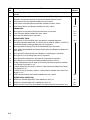
CURRENT STATUS OF PAGES AS
OF
OCTOBER 1996
See "Manual Revisions," in the introduction section for distribution procedure.
THE ORIGINAL DATE OF THIS PUBLICATION IS OCTOBER 1996.
DESTROY SUPERSEDED PAGES.
INSERT LATEST PAGES;
WARNING
If the user of this manual is uncertain whether all current revisions have been incorporated
into the manual, contact Teledyne Continental Motors. Do not perform any operation,
maintenance, installation or other operation until the manual is confirmed current.
MODEL:
PAGE
ALL
TSIO-360-MB & -SB
STATUS
PAGE
FORM X30645A
STATUS
PAGE
STATUS
PAGE
STATUS
ORIGINAL
iii
WARNING
BACKGROUND. Replacement parts, materials and accessories may be sold as being of aircraft
quality when actually the quality and origin of these units are unknown. Users of such units are
usually unaware of potential hazards involved with replacement parts not eligible for use on
certificated aircraft.
Units may be deceptively advertised as "unused," "like new" or
"remanufactured." This implies the quality of such units is equal to an original, repaired or
overhauled unit.
Federal Aviation Regulations (FAR) 43.13 and FAR 145.57 specify performance rules for
replacement of parts and materials used in maintenance and alteration of United States (US)
certificated aircraft. As outlined in FAR 91.403, FAR 121.363, FAR 123.45, and FAR 135.143 (a),
the owner/operator is responsible for continued airworthiness of the aircraft which includes parts
replacement.
IDENTIFICATION OF THE APPROVED PARTS. Approved serviceable replacement parts are
identified by:
a. A Federal Aviation Administration (FAA) Form 8130-3 Airworthiness Approval Tag. An
Airworthiness Approval Tag identifies a part or group of parts approved by authorized FAA
representatives.
b. An FAA Technical Standard Order (TSO) number and identification mark that indicates the
part or appliance has been manufactured under the requirements of FAR 21 Subpart O.
c. An FAA Parts Manufacturer Approval (PMA) symbol, together with the manufacturer's name,
part number and make and model of the type certified product on which the part might be
installed, stamped on the part. An FAA / PMA is issued under FAR 21.305. The make and
model information may be on a tag attached to the part.
d. Shipping ticket, invoice or other document which verifies the part was manufactured by a
facility holding an FAA Approved Production Inspection System issued under FAR 21 Subpart
F or by a manufacturer holding an FAA Production Certificate issued under FAR 21 Subpart G.
e. Certificate of airworthiness for export issued by a foreign government under the provisions of
FAR 21 Subpart N.
KNOW YOUR SUPPLIER. Many reproduced parts and components are available for purchase
and installation on US certified aircraft. Often, an original part is used as a sample to produce
duplicates. The reproduced parts appear to be as good as the original part; however, many
unknown factors are not readily apparent to the purchaser such as degree of heat treating, plating,
inspections, tests and calibrations. Often the faulty part is not discovered until a malfunction or an
accident occurs.
SUMMARY. In accordance with FAR certification of materials, parts and appliances for
return to service for use on aircraft is the responsibility of the person\agency who signs the
approval. The owner/operator is responsible for the continued airworthiness of the aircraft. To
assure continued safety in aircraft operation, great care must be used when inspecting, testing
and determining the acceptability of all parts and materials. Exercise extreme discretion to identify
and establish the origin of materials, parts, and accessories.
iv
NOTICE TO ALL USERS
This manual does not contain maintenance or installation information for supplemental type
certificated components or systems. This manual contains information on engines, components
and systems designed, tested and certified by TCM in accordance with the pertinent type design
data.
The following publication contains information applicable to each engine maintenance
requirement. It is important all personnel involved with these functions thoroughly read and
understand the information provided; these instructions inform of the procedures necessary to
maintain continued airworthiness and they must be followed carefully.
Prior to performing maintenance, the mechanic must meet requirements of FAR 65 and must
follow FAR Parts 43, 91 and 145 as applicable. Use this manual in conjunction with Teledyne
Continental Motors (TCM) service documents, related publications, accessory manufacturer's
instructions, FAR and FAA Advisory Circulars.
This manual contains no warranties, either expressed or implied.
Publication Format
This publication is formatted for practical use and ease of reference. Chapter and page
numbering are independent so that revisions can be made without affecting the entire publication.
Due to the large volume of information necessary for maintenance, maintenance chapters are
independently numbered. For example, chapter 1 begins on page 1; chapter 2 begins again with
page 1, etc. To locate information easily, use the Publication Table of Contents and the Chapter
Contents provided at each division.
WARNING
This manual, the Service Documents, the Overhaul Manual and the Parts Catalog constitute
the instructions for Continued Airworthiness prepared by TCM as approved by the FAA,
pursuant to FAR Part 33. As required by FAR § 43.13, each person performing
maintenance, alteration or preventive maintenance on the engine or accessories must use
the methods, techniques and practices prescribed in the Instructions for Continued
Airworthiness. Failure to comply with the Instructions for Continued Airworthiness may
result in engine malfunction, engine failure, injury or death.
v
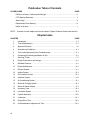
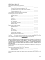
Publication Table of Contents
COVER PAGES
PAGE
Definition of Notes, Cautions and Warnings........................................................................ii
CFC Warning Statement......................................................................................................ii
Status Page.........................................................................................................................iii
Replacement Parts Warning ...............................................................................................iv
Notice to all users................................................................................................................ v
NOTE ... Contents of each chapter are listed in chapter "Chapter Contents" before each division.
Chapter Index
CHAPTER
vi
PAGE
1
Introduction ................................................................................................................... 1-2
2
Tools (Maintenance)..................................................................................................... 2-1
3
Approved Products ....................................................................................................... 3-1
4
Airworthiness Limitations.............................................................................................. 4-1
5
Time Limits/Operational Insp./Troubleshooting ........................................................... 5-1
6
Unpacking/De-Inhibiting/Installation & Test ................................................................. 6-1
7
Servicing, Fluids ........................................................................................................... 7-1
8
Engine Preservation and Storage ................................................................................ 8-1
9
Standard Practices ....................................................................................................... 9-1
10
Engine Maintenance................................................................................................... 10-1
11
Exhaust System.......................................................................................................... 11-1
12
Ignition System ........................................................................................................... 12-1
13
Fuel Injection System ................................................................................................. 13-1
14
Induction System ........................................................................................................ 14-1
15
Air Conditioning System ............................................................................................. 15-1
16
Electrical Charging System ........................................................................................ 16-1
17
Starter & Starter Adapter ............................................................................................ 17-1
18
Accessory Case.......................................................................................................... 18-1
19
Lubrication System ..................................................................................................... 19-1
20
Cylinder Assembly...................................................................................................... 20-1
21
Crankcase................................................................................................................... 21-1
22
Engine Drive Train ...................................................................................................... 22-1
23
Post Maintenance Adjustment & Test ........................................................................ 23-1
CHAPTER 1
SECTION
PAGE
1-1
Scope ...................................................................................................... 1-2
1-2
Related Publications ............................................................................. 1-2
1-3
Manual Revisions .................................................................................. 1-3
1-4
Service Reports and Inquires .............................................................. 1-3
1-5
Description of Engine Model Code ..................................................... 1-4
1-6
Definition of Terms................................................................................ 1-4
1-7
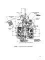
Engine Design Features ....................................................................... 1-4
1-8
General ................................................................................................... 1-9
1-9
Engine Specifications ........................................................................... 1-9
1-10
Operating Limits .................................................................................... 1-9
FIGURE
PAGE
1-1
Engine Description L/TSIO360-RB ...................................................... 1-5
1-2
Engine Description L/TSIO360RB ....................................................... 1-6
1-1
1-1
SCOPE
This publication contains information on maintenance and installation of Teledyne
Continental Motors (TCM) L/TSIO-360-RB
1-2
RELATED PUBLICATIONS
The following are related engine and accessory manuals.
1. Overhaul Manual for L/TSIO-360-RB Series Aircraft engine, Form X30596A
Supplement No.
2. Illustrated Parts Catalog for L/TSIO-360-RB Series Aircraft Engine, Form XX30597A.
Supplement No. 1
3. Operators and Installation Manual for L/TSIO-360-RB Series Aircraft Engine, Form
X30644.
4. Teledyne Continental Motors Aircraft Engine Service Documents (including service
bulletins).
5. Fuel Injection Manual, Form 30593A.
6. Starter Service Instructions, Form X30592.
7. TCM Ignition Systems Master Service Manual, Form No. X40000.
8. Alternator Maintenance and Parts Catalog, Form No. X30631A.
The above publications can be ordered through your Teledyne Continental Motors
Distributor or ordered directly, if prepaid, from:
Teledyne Continental Motors
P.O. Box 90
Mobile, Alabama 36601
ATTN: Publications Sales Department
Telephone: (334) 438-3411
For price information on the above publications see TCM Publications Index Form X-94, Current Publications and Form X-3-94, Optional Publications.
9. Slick Ignition Systems Master Service Manual Form No. F-1100.
Order through:
Slick Aircraft Products
Unison Industries
530 Blackhawk Park Avenue
Rockford, Illinois 61104
ATTN: Subscription Department
Telephone: (815) 965-4700
1-2
1-3
MANUAL REVISIONS
Revisions to this manual will be furnished to purchasers who complete and return the
registration post card in the front of this manual.
Page iii, "Current Status of Pages," is updated at each revision. Remove and discard the
old page iii. Insert the new page iii as a record of which revisions have been incorporated
into the manual.
WARNING
If the user of this manual is uncertain whether all current revisions have been
incorporated into the manual, contact TCM. Do not perform any operation,
maintenance, installation or other operations until the manual has been confirmed to
be current.
1-4
SERVICE DOCUMENTS
TCM service documents include categories for: Mandatory Service Bulletins, Critical Service
Bulletins, Service Bulletins, Service Information Directives, Service Information Letters and
Special Service Notices.
Category Definitions:
CATEGORY 1: MANDATORY SERVICE BULLETIN (MSB) - Service documents relating to
known or suspected hazards to safety that have been incorporated in whole or in part in an
Airworthiness Directive (AD) issued by the FAA or have been issued, at the direction of FAA,
by the manufacturer to require compliance with an already issued AD or an equivalent
issued by another country's airworthiness authority.
CATEGORY 2: CRITICAL SERVICE BULLETIN (CSB) - Service documents determined by
the product manufacturer to constitute a threat to continued safe operation of an aircraft or
to persons or property on the ground unless some specific action (inspection, repair,
replacement, etc..) is taken by the product owner or operator. Documents in this category
may be candidates for incorporation in an Airworthiness Directive issued by the FAA.
CATEGORY 3: SERVICE BULLETIN (SB) - Service documents considered by the product
manufacturer to constitute a substantial improvement to the inherent safety of an aircraft or
component of an aircraft.
CATEGORY 4: SERVICE INFORMATION DIRECTIVE (SID) - Service documents
determined by the manufacturer to enhance safety, maintenance or economy.
CATEGORY 5: SERVICE INFORMATION LETTER (SIL) - This category provides general
information that may be useful to the owner/operator or aircraft maintenance technician
(AMT).
SPECIAL SERVICE NOTICE (SSN) - TCM may issue a Special Service Notice when a
product condition can be rectified by direct contact with each customer to whom the product
was delivered. Special service notices will be upgraded to Service Bulletins if confirmation
of compliance with the Special Service Notice cannot be verified by TCM.
SERVICE REPORTS AND INQUIRIES. If you have an inquiry or require technical
assistance, contact a TCM distributor, field representative or customer service.
1-3
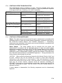
1-5
DESCRIPTION OF ENGINE MODEL CODE
Example code: L/TSIO-360-RB (1)
1-6
L
TS
I
O
360
RB
1
Left hand
rotation
Turbo super
charged
Fuel injection
Horizontally
opposed
Displacement
(360 cubic inch)
model
specification
number
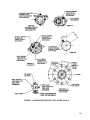
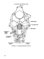
DEFINITION OF TERMS
Front, rear, left and right refer to the engine view facing the accessory end. The accessory
end is referred to as the rear and propeller flange the front of the engine. Cylinders are
numbered starting from the rear with odd numbers on the right and even numbers on the
left.
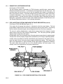
1-7
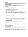
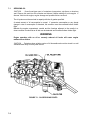
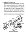
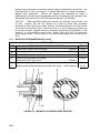
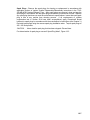
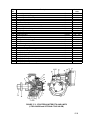
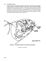
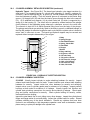
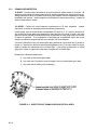
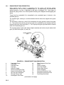
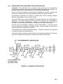
ENGINE DESIGN FEATURES
The L//TSIO-360-RB series The L//TSIO-360-RB series engines are air cooled, having six
horizontally opposed overhead inclined valve cylinders. The cylinder displacement of 360
cubic inches is achieved with a 4.4 inch bore and a 3.875 inch stroke. The L/TSIO-360-RB
series engines are fuel injected. The crankshaft is equipped with pendulum type
counterweight dampers that suppress torsional vibrations.
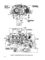
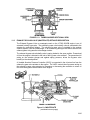
The L/TSIO-360-RB series engine have a doweled six bolt hole configuration propeller
flange. A mounting pad is provided to utilize a hydraulic controlled governor for a constant
speed propeller.
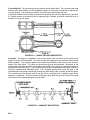
The L/TSIO-360-RB series engines are designed with a wet sump and a positive
displacement oil pump. When properly adjusted under normal operating conditions, the
desired oil pressure is maintained by a pressure relief valve. Engine cranking is
accomplished by a geared right angle drive starter adapter and a direct current starter
motor.
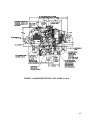
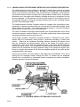
The L/TSIO-360-RB series incorporate provisions for a belt driven alternator installed on the
from 1-3-5 side of the crankcase. The engine is equipped with two gear driven magnetos
mounted on the accessory case. The exhaust and turbocharging system is supplied with
the engine.
1-4
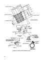
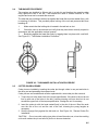
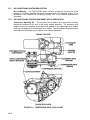
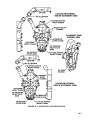
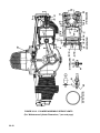
FIGURE 1-1. Engine Description L/TSIO-360-RB
1-5
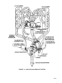
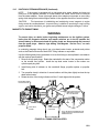
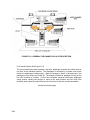
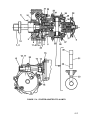
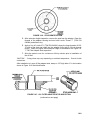
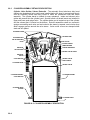
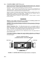
FIGURE 1-2. ENGINE DESCRIPTION L/TSIO 360-RB (Cont’d)
1-6
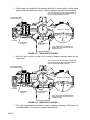
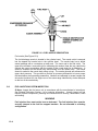
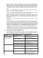
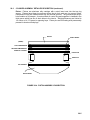
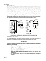
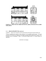
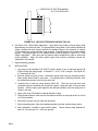
FIGURE 1-2. ENGINE DESCRIPTION L/TSIO 360-RB (Cont’d)
1-7
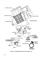
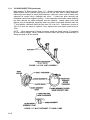
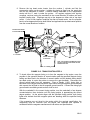
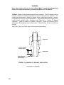
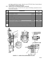
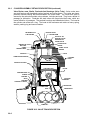
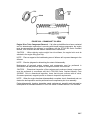
FIGURE 1-2. ENGINE DESCRIPTION L/TSIO 360-RB (Cont’d)
1-8
FIGURE 1-2. ENGINE DESCRIPTION L/TSIO 360-RB (Cont’d)
1-9
1-8
GENERAL
The operating limits and specifications listed in this section are applicable to the L/TSIO360-RB series aircraft engines. Consult the L/TSIO-360-RB Operator & Installation Manual,
Form X30644 for additional operating procedures.
For time between overhaul (TBO) for L/TSIO-360-RB series engines see section 5-2 and the
latest TBO Service Bulletin (Overhaul Periods For All Teledyne Continental Aircraft
Engines). Accessories supplied with engine by TCM have the same TBO; with criteria for
service and longevity outlined in current TCM TBO Service Bulletins, unless otherwise
specified.
1-9
ENGINE SPECIFICATIONS
Manufacturer
Teledyne Continental Motors
Model L/TSIO-360-RB.
Cylinders
Arrangement .......................... Individual cylinders in a horizontally opposed position
Compression Ratio .............................................................................................. 7.5:1
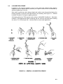
Firing Order (TSIO-360-RB) ...................................................................... 1-6-3-2-5-4
Firing Order (LTSIO-360-RB) ................................................................... 1-4-5-2-3-6
Number of cylinders ................................................................................................... 6
Bore (Inches) ..................................................................................................... 4.438
Stroke (Inches)................................................................................................... 3.875
Piston Displacement (cu. in.) ................................................................................ 360
Brake Horsepower
Rated Maximum Continuous Operation L/TSIO-360-RB, .............................220 BHP
1-10
OPERATING LIMITS
NOTE . . . The following specifications apply to all L/TSIO-360-RB engines unless otherwise
specified.
Crankshaft Speed - RPM
L/TSIO-360-RB
Rated Maximum Continuous Operation ..................................................... 2600 RPM
Idle...........................................................................................................700 RPM±25
Manifold Pressure Limit (In. Hg.) Absolute.......................................................... 38.0”
Fuel Control System .................................................. Precision RSA-5 Fuel Injection
Fuel .............................................................For fuel grade , see Chapter 7, Servicing
Oil ................................................ For Oil grade & capacity, see Chapter 7, Servicing
Oil Pressure
Idle, Minimum, psi ................................................................................................... 10
Normal Operation, psi .................................................................................... 30 to 60
Oil Sump Capacity (U.S. Quarts) ........................................................................... 8.0
Oil Consumption (Lb./BHP/Hr. Max.) ............................................. .006 X % Power
100
1-10
1-10
OPERATING LIMITS (Cont’d)
Oil Temperature Specifications
All Temperatures .........................................................TCM Approved Multi Viscosity
Below 40°F Ambient (Sea Level) .............. TCM Approved SAE 30 or Multi Viscosity
Above 40°F Ambient (Sea Level).............. TCM Approved SAE 50 or Multi Viscosity
Oil Temperature Limits
Minimum for Take-Off....................................................................................... 100°F
Maximum Allowable.......................................................................................... 240°F
Recommended Operational Range ......................................................... 160 - 180°F
Cylinder Head Temperature
TSIO-360-RB
Recommended maximum at cruise....................................................................420°F
Limit ....................................................................................................................460°F
Turbine Inlet Temperature
Maximum Continuous .....................................................................................1650°F
Maximum, 60 seconds ....................................................................................1700°F
Ignition Timing (Compression stroke, breaker opens)
Right Magneto, degrees BTC............................................................................22°±1°
Left Magneto, degrees BTC ..............................................................................22°±1°
The following spark plugs are approved for use in engine models according to the following
listing:
L/TSIO-360-RB.
Use:
TCM
630049
Champion,
RHM38E
Spark Plug Gap
Use spark plug manufacturer's specified gap.
1-11
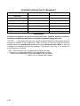
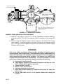
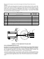
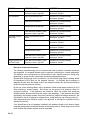
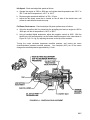
ACCESSORY DRIVE RATIOS TO CRANKSHAFT
Accessory
Direction of Rotation*
Drive Ratio
Tachometer
-
Magneto
CW
1.5:1
Starter
CW
24.73:1
* ** Propeller Governor
CW
1:1
Fuel Pump (Injection),
CCW
1:1
Freon Compressor
CW
1.545:1 * * * *
* * * Accessory Drive Pad
CCW
1.545:1
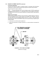
WARNING
Oil pressure is applied to the face of accessory drive pads. If gaskets, accessory or cover is
not properly installed and hardware is not properly torqued oil leakage will occur.
CAUTION . . . A removable oil transfer plug conducts oil under pressure from the propeller governor
through the crankshaft to the propeller hub. When a test club or fixed pitch propeller is used for
testing purposes the governor pad cover must have an internal grooved surface to allow the
circulating oil to lubricate the front main bearings. The governor pad cover is not needed if a
propeller governor is installed.
* “CW” - Clockwise and CCW – Counterclockwise (facing drive pad).
* * This drive is a modified AND 20010 and is supplied with cover plate.
* * * This drive is a modified AND 20000 and is supplied with cover plate.
* * * * Ratio is for 6.0" diameter driven sheave.
1-12
CHAPTER 2
TOOLS AND EQUIPMENT
Section
Page
2-1
General Information................................................................................................ 2-2
2-2
Possible Special Tool Procurement Sources......................................................... 2-3
2-3
Special Tools ......................................................................................................... 2-4
2-1
2-1
GENERAL INFORMATION
The mechanic should be equipped with a complete set of the necessary tools that include
the following:
1. Wrenches - 1/4" through 1 1/4"
2. Common and Philips Head Screwdrivers
3. Pliers - Common Diagonal Cutters, Needle Nose, Duck Bill, Snap Ring
4. Ratchets 1/4”,3/8”, & 1/2” Drive
5. Sockets - 1/4” Drive 5/32” through 1/2” / 3/8” Drive 3/8” through 1" / 1/2” Drive 7/16”
through 1-1/4”
6. Sockets (Deepwell) - 1/2" Drive 7/16" through 1"
7. Feeler Gauges
8. Leather or Soft Plastic Mallet
9. Torque Wrenches* 0-500 In. Lbs. / 0-100 Ft. Lbs.
10. Micrometers*
11. Slide Hammer
12. Pullers
13. Thickness Gauges
14. Vernier Calipers*
15. Small Hole Gauges
16. Ford Wrench
* Must be currently calibrated, and the calibration must be traceable to the National Bureau
of Standards.
2-2
2-2
POSSIBLE SPECIAL TOOL PROCUREMENT SOURCES
- NOTICE All tools in the "Special Tool" list are for reference only, and not for the purpose of promoting
or suggesting tools to be purchased from the indicated sources. The following information is
given as an aid for special tool procurement purposes.
COMPANY
GENERAL PRODUCT SUMMARY
ALCOR
Box 32516
10130 Jones Maltsberger Rd.
San Antonio, TX 78284
(512) 349-3771
Instruments for Light Powered Aircraft
Special Tools
KENT - MOORE
29784 Little Mack
Roseville, MI 48066-2298
(800) 253-0138
Precision Instruments
Measuring Instruments
Precision Tools
Special Tools
CHAMPION SPARK PLUG, CO.
Box 910, 900 Upton Ave.
Toledo, OH 43661
(419) 535-2461
EASTERN ELECTRONICS, INC.
180 Roberts St.
East Hartford, CT 06108
(203) 528-9821
FEDERAL TOOL SUPPLY CO. INC.
1144 Eddy St.
Providence, Rhode Island 02940
(800) 343-2050
AIRCRAFT TOOL SUPPLY
P.O. Box 4525, 2840 Breard St.
Monroe, LA 71201
(507) 451-5310
McMASTER-CARR SUPPLY CO.
P.O. Box 4355
Chicago, Illinois 60680
(312) 833-0300
SNAP ON TOOLS
2611 Commerce Blvd.
Birmingham, Alabama 35210
(205) 956-1722
Kell-Strom Tool Company, Inc.
214 Church St.
Wethersfield, CT 06109
Spark Plugs Ignitors
Oil Filters
Special Tools
Krautkramer Branson
P.O. Box 350
Lewiston PA 17044
(717) 242-0327
Merrit Products
201 W. Mansville
Compton, California 90224
310/639-4242
Ultrasonic Test Equipment
Fuel Pressure Test Equipment
Measuring Instruments
Precision Tools
Piston Position Indicators
Precision Inspection Instruments
Special Tools
Precision Tools
Special Tools
Precision Tools
Special Tools
Precision Tools
Special Tools
Ignition Test Equipment
Special Tools
2-3
COMPANY
APPROVED AIRCRAFT ACCESSORIES INC.
29300 Goddard Road
Romulus, Michigan 48174
(313) 946-5547
2-3
GENERAL PRODUCT SUMMARY
Model 20 ATM-C Porta-Test Unit
SPECIAL TOOLS
Specific tools listed or equivalent tools marketed by other manufacturers are necessary for
overhaul and maintenance of the aircraft engine.
ITEM
NO.
TOOL
See
Section
GENERAL ENGINE RECIPROCATING
1
646953 Master Orifice Tool for cylinder compression test available from Kent - Moore
5-4
2
7251 Differential Pressure Cylinder Checker available from Kent - Moore
5-4
IGNITION SYSTEM
3
Borrough's 3608A Protractor/Timing Indicator Disc or equivalent for setting engine timing
12-6
4
Model E25 Timing Indicator available from Eastern Electronics, Inc.
12-7
5
11-9110-1 Magneto Timing Light available from KELL-STROM Tool Company Inc.
12-7
FUEL INJECTION
6
Borrough's 8165 Injector Nozzle Remover and Installer or equivalent
13-3
CHARGING SYSTEM
7
Borrough's 7726 Torch Band Tension Adjuster or equivalent for Gen./Alt. Belt
Tensioning
16-5
8
BTU-33-73F Belt Tension Gage available from Kent - Moore
16-5
9
Borrough's 4973 Generator Drive Holders or equivalent
16-5
10
Borrough's 61-5 Pulley Pulled or equivalent for gen./alt. sheave removal
16-5
11
Borrough's 8091 GEN./ALT. Output Tester or equivalent.
16-5
12
647 Alternator Analyzer Voltage Regulator Tester available from Eastern Electronics,
Inc.
16-5
13
E100 Alternator/Regulator/Battery Tester available from Eastern Electronics, Inc.
16-5
14
Model 29 Voltage & Circuit Tester available from Eastern Electronics, Inc.
16-5
STARTING SYSTEM
15
Borrough's 8093C Bearing Puller or equivalent for needle bearing removal
17-5
16
Borroughs 23-1 Needle Bearing Installer or equivalent
17-5
LUBRICATION SYSTEM
17
8048 Oil Pressure Relief Spot Facer available from Kent - Moore
19-3
18
68-3 Push Rod Spring Compressor available from Kent - Moore
20-6
19
3882 Cylinder Base Nut Wrenches available from Kent - Moore
20-6
20
Borrough's 8079 Cylinder Base Nut Wrenches or equivalent
20-6
21
3882, 3882-2 Cylinder Base Nut Wrenches available from Kent - Moore
20-6
22
3601 Ring Compressor for cylinder installation available from Kent - Moore
20-6
23
8121 Piston Pin Removers available from Kent - Moore
20-6
24
3602 Valve Spring Compressor available from Kent - Moore
20-6
CYLINDERS
2-4
ITEM
NO.
TOOL
Courtesy of Bomar Flying Service
www.bomar.biz
See
Section
25
545-116 Dial Bore Gages available from Federal Tool Supply Co. Inc.
20-6
26
CFL10 Cylinder Hone available from Snap On Tools
20-6
27
No. 1675 Valve Seat Grinder Set "Sioux Brand" available from Aircraft Tool Supply
20-6
28
AEX 375 Valve Seat Grinder Pilot .437 Dia. available from Aircraft Tool Supply
29
K28 Intake Valve Seat Grinding Stone (Roughening 45°) available from Aircraft Tool
Supply
30
K98 Intake Valve Seat Grinding Stone (Finishing 45°) available from Aircraft Tool Supply
31
K428 Exhaust Valve Seat Grinding Stone (Roughening 45°) available from Aircraft Tool
Supply
32
K498 Exhaust Valve Seat Grinding Stone (Finishing 45°) available from Aircraft Tool
Supply
33
Borrough's 5221A Holding Fixture Adapters or equivalent
34
Borrough's 5221B Cylinder Holding Fixture or equivalent
35
Borrough's 8156 Cylinder Heating Stand or equivalent
36
Borrough's 8086 Valve Seat Insert Remover & Replacer or equivalent
37
Borrough's 4910 Installer Valve Seat Insert or equivalent
38
Borrough's 4956 Installer Valve Seat Insert or equivalent
39
Borrough's 8116 Common Parts Kit or equivalent
40
Borrough's 8116-1B through 15B Boring Bars or equivalent
41
Borrough's 8116-1R through 15R Reamers or equivalent
42
Borrough's 8116-1 through 16 Expanding Guide Bodies or equivalent
43
4909 Valve Seat (Straight Side) Insert Cutters available from Kent - Moore
4954 Valve Seat (Straight Side) Insert Cutters available from Kent - Moore
4985 Valve Seat (Straight Side) Insert Cutters available from Kent - Moore
5224 Valve Seat (Straight Side) Insert Cutters available from Kent - Moore
5225 Valve Seat (Straight Side) Insert Cutters available from Kent - Moore
44
8135 Valve Seat (Step Side) Insert Cutters available from Kent - Moore
8136 Valve Seat (Step Side) Insert Cutters available from Kent - Moore
8138 Valve Seat (Step Side) Insert Cutters available from Kent - Moore
45
Borrough's 8122A Common Drive Handle or equivalent
46
122 Valve Guide Cleaner available from Kent - Moore
47
2873 Valve Guide Remover available from Kent - Moore.
48
3619 Valve Guide Replacer available from Kent - Moore
49
Borrough's 3170 Floating Holder or equivalent
50
4981 Valve Guide Remover available from Kent - Moore
51
Borrough's 8116-24 through 29 Valve Stem Hole Reamers or equivalent
52
3606-CP Reamer (Carbide Tipped) available from Kent - Moore
53
2684 Reamer to Morse Taper Adapter (Square Shank) available from Kent - Moore
54
2848 Plug Gage for valve guide inspection available from Kent - Moore
55
4943-1HS through 5HS Reamers, Valve Guide Boss available from Kent - Moore
56
Borrough's 4918 Spark Plug Insert Replacer or equivalent
57
Borrough's 4919 Spark Plug Insert Remover or equivalent
3606-HP Reamer (High Speed Steel) available from Kent - Moore
2-5
ITEM
NO.
TOOL
See
Section
58
Borrough's 445, 18mm Spark Plug Tap or equivalent for straightening out damaged
threads
20-6
59
2769A13 Rosan® Stud Remover available from McMASTER-CARR Supply Co.
20-6
Rosan® is a registered trademark of Fairchild Aerospace Fastener Division
60
8074 Rosan® Lock Ring Installer available from Kent - Moore
61
8118 Rocker Arm Bushing Remover/Installer available from Kent - Moore
62
3610 Reamer Rocker Arm Bushing available from Kent - Moore
63
Borrough's 8114 Crankcase Through Bolt Removers or equivalent
21-5
64
L423 Crankcase Splitter available from Kent - Moore
21-5
65
Borrough's 505 Stud Drivers or equivalent
21-5
20-6
CRANKCASE
ENGINE DRIVE TRAIN
66
Borrough's 8117A Runout Block Set or equivalent for crankshaft inspection
67
Krautkramer Branson Model USK 7D, USL42, USL 48, USN 50, USN 52, or OR7S for
Crankshaft Ultrasonic Testing available from Fax Corporation
68
Borrough's 8087A Polishing Tools for Crankshaft Bearings or equivalent
69
3604, 8068 Crankshaft Blade and Damper Bushing Remover/Replacer available from
Kent - Moore
70
Borrough's 8077C Bushing Remover & Replacer, Counterweight or equivalent
71
Borrough's 8111A Connecting Rod Fixture or equivalent
72
Borrough's 8072C Adapter Kit or equivalent for connecting rod inspection
73
8071 Reamers for connecting rod bushing available from Kent - Moore
74
D-4000 Federal Dimension Air Gage for connecting rod bushing inspection available
from Federal Tool Supply Co. Inc.
75
1.00025 Setting Ring for checking 1.0000 to 1.0005 tolerance available from Federal
Tool Supply Co. Inc.
76
1.00025 Air Plug for checking 1.0000 to 1.0005 tolerance available from Federal Tool
Supply Co. Inc.
77
5209 Propeller Shaft Oil Seal Installer available from Kent - Moore
22-5
22-5
OPERATIONAL INSPECTION
78
85328 Alcor Portable Digital EGT Unit available from Alcor, Inc.
23-1
79
85329 Alcor Portable Digital CHT available from Alcor, Inc.
23-1
80
Model 20 ATM-C Porta-Test Unit available from Approved Aircraft Accessories, Inc.
23-1
2-6
CHAPTER 3
SEALANTS AND LUBRICANTS
Sealants / Lubricants ...................................................................................................................... 3-2
3-1
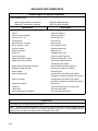
SEALANTS AND LUBRICANTS
Aviation Engine Oil Ashless Dispersant
Recommended Grade
Above 40°F ambient air, sea level
Below 40°F ambient air, sea level
SAE 50 or Multi Viscosity
SAE 30 or Multi Viscosity
Manufacturer
Brand Name
BP Oil Corporation
BP Aero Oil
Castrol
Castrol Aero AD Oil
Castrol Limited (Australia)
Castrol Aero AD Oil
Chevron U.S.A., Inc.
Chevron Aero Oil
Continental Oil
Conco Aero S
Delta Petroleum Company
Delta Avoil Oil
Exxon Company, U.S.A.
Exxon Aviation Oil EE
Gulf Oil Company
Gulfpride Aviation AD
Mobil Oil Company
Mobil Aero Oil
NYCO S.A.
TURBONYCOIL 3570
Pennzoil Company
Pennzoil Aircraft Engine Oil
Phillips Petroleum Company
Phillips 66 Aviation Oil, Type A
Phillips Petroleum Company
X/C Aviation Multiviscosity Oil
SAE 20W50, SAE 20W60
Quaker State Oil & Refining Company
Quaker State AD Aviation Engine Oil
Red Ram Limited (Canada)
Red Ram X/C Aviation Oil 20W50
Shell Australia
Aeroshell (R) W
Shell Canada Limited
Aeroshell Oil W, Aeroshell Oil W 15W50
Anti-Wear Formulation Aeroshell Oil W 15W50
Shell Oil Company
Aeroshell Oil W, Aeroshell Oil W 15W50
Anti-Wear Formulation Aeroshell Oil W 15W15
Sinclair Oil Company
Sinclair Avoil
Texaco Inc.
Texaco Aircraft Engine Oil - Premium AD
Total France
Total Aero DM 15W50
Union Oil Company of California
Union Aircraft Engine Oil HD
Break-in Oil
MIL-C-6529 Type II Corrosion preventive mineral oil
NOTE . . . Mineral oil conforming with MIL-C-6529 Type II contains a corrosion preventive additive and must
not be used for more than 25 hours or six months, whichever occurs first. If oil consumption has not
stabilized in this time, drain and replenish the oil and replace the oil filter.,
3-2
Preservative Oil
TYPE
SUGGESTED SOURCES
APPLICATION
MIL-C-6529 Type II
(Aeroshell Fluid 2F or equivalent),
MIL-P-46002
Grade 1 oil, (NOX RUST VCI-105
or equivalent) May be purchased
through:
Rock Island Lubricant & Chemical
Co.
P.O. Box 5015
1320 1st Street
Rock Island, Illinois 61204
Phone: 1-800-522-1150
For Temporary storage (up to 90
days)
For Indefinite storage
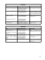
Lubricants
TYPE
SUGGESTED SOURCES
APPLICATION
Molyshield Grease
May be purchased through:
Needle bearings and ball bearings
American Lubricants
Valve stems
1227 Deeds
Dayton, Ohio 45401
All ACC
couplings
Phone: (513) 222-2851
Idler gear and pin
drive
splines
and
Fuel injection controls, o-rings,
springs, shafts and bushings
Magneto rubber drive bushings
Dow Corning® G-N Paste
[Dow Corning® G-N Paste is a
registered trademark of Dow
Corning Corporation.]
For Distributor information call
1-800-248-2481, have state & city
information available
Camshaft lobes and lifter faces
Alvania (Shell #2)
For Distributor information: Shell
Product
Information
Center,
Phone: 1-800-231-6950
Front crankshaft oil seal
MIL-S-3545C Grease (Shell #5)
Shell Product Information Center,
Phone: 1-800-231-6950
Fuel injection linkage pivot points,
throttle shaft bushings, lever
bushings
Permatex Maintain® Lubricant
For Distributor information call:
Permatex Customer Service @
Phone: 1-800-641-7376
Fuel injection linkage pivot points,
throttle shaft bushings,
lever
bushings
#646943 - Anti Seize Lubricant
or
Loctite Anti-Seize Lubricant 767
May be purchased through
your local TCM Distributor
or
All fuel injector
cylinder head)
For Distributor information: Loctite
Customer Service @
Exhaust studs (nut end before
torquing)
Phone: 1-800-243-4874
All class 4 studs
nozzles
(at
All mechanical tach drive housing
threads
3-3
Lubricants
TYPE
SUGGESTED SOURCES
APPLICATION
Approved Ashless Dispersant Oil
See Aviation Engine Oil Ashless
Dispersant Table
Cylinder studs and through bolts,
crankcase studs, connecting rod
bolts and nuts and engine
accessory studs unless otherwise
specified
CHAMPION® - Spark Plug
Thread Lubricant No. 2612
[CHAMPION® is a registered
trademark of Cooper Industries.]
For
Champion
Products
Distributor information: Phone:
803-843-5400
Spark plugs
Chesterton No. 4
Chesterton Technical Product
Information
Phone: (508) 469-6783
For Distributor information call
1-800-248-2481 have state & city
information available
Induction
connections
Dow Corning® No. 4
system
hose
Spin-on oil filter rubber seals
Sealants
TYPE
Permatex Aviation Grade 3D
and
#641543 Silk Thread
and
#646942 Gasket Maker
or
Loctite Gasket Eliminator
515 Sealant
#653692 - Primer
SUGGESTED SOURCES
For Distributor information call:
Permatex Customer Service @
Phone: 1-800-641-7376
APPLICATION
Crankcase parting face, oil pump
covers, scavenge pump covers
May be purchased through
your local TCM Distributor
May be purchased through
your local TCM Distributor
For Distributor information call:
Loctite Customer Service @
Phone: 1-800-243-4874
May be purchased through
your local TCM Distributor
Crankcase crankshaft nose oil
seal area
or
Loctite LocQuic Primer 7649
#646942- Gasket Maker
For Distributor information:
Loctite Customer Service @
Phone: 1-800-243-4874
May be purchased through your
local TCM Distributor
or
Loctite Gasket Eliminator
515 Sealant
#642188 - Gasket Sealant
(TCM) 1.5 oz. tube
3-4
For Distributor information:
Loctite Customer Service @
Phone: 1-800-243-4874
May be purchased through
your local TCM Distributor
or
Engine nose seal, outside
diameter of all uncoated oil seals,
non-beaded oil sump gaskets
Cam bore cover gasket, idler pin
gasket, oil filler neck gasket and
holes, pressed in plugs
Sealants
TYPE
Loctite Teflon PS/T Pipe Sealant
#646940 - F/I Sealant
SUGGESTED SOURCES
K & W Copper Coat
For Distributor information call:
K & W Products Customer
Phone: 1-800-423-9446
For Distributor information:
Loctite Customer Service @
Phone: 1-800-243-4874
May be purchased through
your local TCM Distributor
APPLICATION
Pipe threads, pressure relief
valve housing threads, tach drive
threads, oil temperature control
valve, studs that are exposed to
oil
All pipe thread fittings in fuel
injection system
or
Loctite Hydraulic Sealant 569
Miller-Stephenson
MS 122/C02 Spray
For Distributor information:
Loctite Customer Service,
Phone: 1-800-243-4874
For Distributor information:
Miller-Stephenson Customer
Service, Phone: 1-800-992-2424
Ignition harness terminals
magneto block end
at
Adhesives
TYPE
646941 High Strength Adhesive
Sealant or Loctite 271
SUGGESTED SOURCES
May be purchased through
your local TCM Distributor
653696 Primer or Loctite LocQuic
Primer 7471
For Distributor information:
Loctite Customer Service,
Phone: 1-800-243-4874
May be purchased through
your local TCM Distributor
For Distributor information:
Loctite Customer Service,
Phone: 1-800-243-4874
3M
649306 Sealant (optional 646940)
or Loctite Adhesive Sealant 222
(optional
Loctite
Hydraulic
Sealant
569),
3M Brand EC1252 White Spot
Putty
APPLICATION
Cylinder deck studs, squirt
nozzles, fuel manifold valve
diaphragm and plunger assembly
Through stud holes on accessory
end of crankcase, manifold valve
to bracket screws
Cylinder deck studs, magneto
flanges, throttle body and fuel
metering unit
3-5
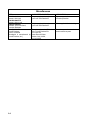
Miscellaneous
TYPE
TCM P/N 626531-1
Enamel - Gold (1qt)
TCM P/N 626531-2
Enamel - Gold (1 gal)
TCM P/N 535001S
Lockwire -.032 in dia. Steel,
Corrosion Resistant
“ACCELAGOLD”
Turco® Products
Tucker, GA 30084
[Accelagold is manufactured by
Turco® Products, Inc.]
3-6
SUGGESTED SOURCES
May be purchased through
your local TCM Distributor
APPLICATION
High temp. paint for cosmetic and
corrosion protection
May be purchased through
your local TCM Distributor
Where applicable for lockwiring
For sales and service: Elf Atochem
N.A. Turco® Products Div.
P.O. Box 195
State Route 95 West
Marion, Ohio, 43302,
215-419-5376
Corrosion protection interior and
exterior aluminum parts
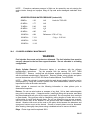
CHAPTER 4
AIRWORTHINESS LIMITATIONS
This Airworthiness Limitations section has been FAA approved and specifies maintenance required
under §§ 43.16 and 91.403 of the Federal Aviation Regulations unless an alternative program has
been FAA approved. Federal Aviation Regulations §§ 43.16 and 91.403 require owner/operator
compliance with all maintenance limitations in this section concerning mandatory replacement
times, inspection intervals and other related procedures that are specific to this engine. Any such
limitations listed below are part of the design limits of the engine and the engine was type
certificated based upon required owner/operator compliance with the limitations.
1. Mandatory Replacement Times.
Subject to additional information contained in FAA Airworthiness Directives (AD) issued after the
date of certification, the engines covered in this manual do not contain any components having
mandatory replacement times required by type certification.
2. Mandatory Inspection Intervals.
Subject to additional information contained in FAA Airworthiness Directives (AD) issued after the
date of certification, the engine does not require specific intervals of inspection pursuant to type
certification.
3. Other Related Procedures
Subject to additional information contained in the Airworthiness Directives (AD) issued after the date
of certification, there are no other related procedures required pursuant to the type certification
for this engine.
4. Distribution of Changes to Airworthiness Limitations.
Changes to the Airworthiness Limitations section constitute changes to the type design of this
engine and require FAA approval. Such changes will be published in FAA Airworthiness
Directives (AD).
NOTE
The limitations in this section apply only to specific limitations which are part of the engine design.
Under the Federal Aviation Regulations numerous other additional limitations are applicable to this
engine and it's accessories. For example Federal Aviation Regulation Parts 91 and 43, among other
parts, define inspection criteria, maintenance requirements and procedures that are applicable to
this engine. It is the responsibility of the owner / operator to maintain the engine in an airworthy
condition by complying with all applicable Federal Aviation Regulations and by performing
maintenance in accordance with TCM Instructions for Continued Airworthiness, which consist of
TCM publications and service documents.
4-1
INTENTIONALLY
LEFT
BLANK
4-2
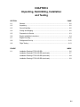
CHAPTER 5
TIME LIMITS/OPERATIONAL INSPECTION/ENGINE
TROUBLESHOOTING
SECTION
PAGE
5-1
General .................................................................................................. 5-2
5-2
Overhaul Periods ................................................................................... 5-2
5-3
Operational Inspection........................................................................... 5-3
5-4
Test Operating Limits ............................................................................ 5-4
5-5
Time Interval Inspections....................................................................... 5-5
5-6
Scheduled Maintenance........................................................................ 5-6
5-7
Unscheduled Maintenance.................................................................. 5-11
5-8
General Information............................................................................. 5-14
5-9
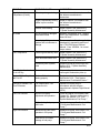
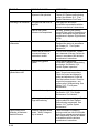
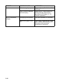
Engine Troubleshooting Chart............................................................. 5-14
5-1
5-1
GENERAL
The scheduled inspection and maintenance described in this section must be complied with
in addition to all aircraft manufacturer and accessory manufacturer inspection and
maintenance requirements. This manual does not contain inspection or maintenance
requirements for supplemental type certificated components or systems. Such information
must be obtained from the supplemental type certificate holder.
Safety, efficiency and engine service life is predicated on compliance with the aircraft and
engine manufacturer's required instructions, inspections and maintenance schedule. The
owner/operator is primarily responsible for maintaining the engine in an airworthy condition,
including compliance with applicable Airworthiness Directives as specified in Part 39 of the
Federal Aviation Regulations (FAR); reference FAR 91.163.
NOTE . . . Engine operational inspection must be performed before and after any 50 or 100hour inspections or maintenance in accordance with "Operational Inspection" requirements
described in this manual (See Chapter Contents).
During engine 50 and 100-hour inspections, if engine components must be replaced, refer to
the applicable system maintenance chapter. Adjustment information will be found in the
individual system chapters of this section.
NOTE . . . The figures depicted in this section are for illustration purpose only. They are not
intended to be accurate detailed illustrations of any specific engine model, part or
equipment.
WARNING
When performing any inspection or maintenance, always treat the engine as if the
ignition switch was on. Do not stand or allow anyone else to stand within the arc of
the propeller. A loose or broken wire or a component malfunction could cause the
engine and propeller to rotate and/or the engine to start.
Engines operated in extremely humid locations or in exceptionally cold, damp climates or
coastal areas may require more frequent inspections. If the engine is operated in excess of
100 hours per year, the engine must be inspected at each 100-hour interval in addition to an
annual inspection.
5-2
OVERHAUL PERIODS
Engine Model
L/TSI0-360-RB
Overhaul Period
1800 HOURS
NOTE . . . Overhaul periods for the engine include all engine accessories.
5-3
OPERATIONAL INSPECTION
An operational inspection must be performed prior to 50/100-hour inspections.
STARTING
Start engine using the starting procedure given in the airframe manufacturers Airplane Flight
Manual (AFM).
5-2
OPERATIONAL CHECK LIST
Check and record the following system data :
Starter ........................................................................................................ _________
*Record RPM Drop for each magneto at 1700
(150 RPM MAXIMUM AND 50 RPM SPREAD MAXIMUM) .............. _________
*Propeller Operation at 1700......................................................... _________
*Or as specified in aircraft manufacturer's instructions.
Increase engine to full power and record:
Manifold Pressure.......................................................................... _________
RPM............................................................................................... _________
Fuel Flow ....................................................................................... _________
Oil Pressure ................................................................................... _________
Oil Temperature............................................................................. _________
Cylinder Head Temperature .......................................................... _________
Alternator Output ........................................................................... _________
Reduce engine to idle and record:
Manifold Pressure.......................................................................... _________
RPM............................................................................................... _________
Oil Pressure ................................................................................... _________
Oil Temperature............................................................................. _________
Cylinder Head Temperature .......................................................... _________
Magneto System Grounding Check .............................................. _________
CAUTION . . . The magneto system grounding check must be accomplished at idle RPM
only. Damage to the engine may result at engine speeds above idle RPM.
WARNING
Absence of RPM drop when checking magnetos is an indication of a malfunction in
the ignition system resulting in a hot magneto. This type of malfunction must be
corrected prior to continued operation of the engine. The engine may inadvertently
experience ignition or start-up anytime the propeller is moved. Damage, injury or
death may result.
If engine continues to run when magnetos are switched Off a malfunction is occurring in the
ignition system.
Slowly move mixture control to IDLE CUT OFF and record:
Mixture RPM Rise ( 25 to 50 RPM )............................................. __________
Positive Fuel Cutoff ..................................................................... __________
When propeller stops rotating, place ignition switch, master switch and fuel selector in off
position.
5-3
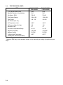
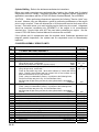
5-4
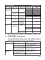
TEST OPERATING LIMITS
ITEM
ENGINE MODEL
TSIO-360-RB
ENGINE MODEL
LTSIO-360-RB
* Full Throttle Speed- RPM
2600
2600
Manifold Pressure In. hg. Absolute
38.0
38.0
Idle Speed - RPM
700±25
700±25
Fuel Grade (Octane)
100LL/100
100LL/100
Fuel Flow at
Full Throttle (Lbs. /Hr.)
140 - 150
140-150
Oil Temperature Limit
240°F
240°F
Oil Pressure (Max. Oil Cold)
100
100
Minimum at Idle
10
10
Oil Pressure Operational Range
30 - 80
30 - 80
Magneto Drop (Max.)
Magneto Spread
150 RPM
50 RPM
150 RPM
50 RPM
Cylinder Head Temperature
with Bayonet Thermocouple (Max.)
460°F
460°F
* Maximum RPM may not be attainable at static run-up depending on setting of propeller low pitch
stops
5-4
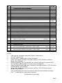
5-5
TIME INTERVAL INSPECTIONS
Inspection procedures and maintenance information are provided in the individual system
chapters.
Engine mounted accessories not supplied by TCM may require servicing at specific
intervals; some of these are alternators, pneumatic pumps, air / oil separators and stand-by
generators. Refer to the instructions provided by the aircraft manufacturer, accessory
manufacturer or STC holder for detailed information.
CAUTION . . . New, rebuilt and overhauled engines or engines that have had overhauled or
new cylinders and new piston rings installed must be given a 100-hour inspection after 25
hours of operation.
Oil Change Interval: *
With small full flow filter ..............................................50 hours
With large full flow filter ...............................................100 hours
Oil Filter Change Interval: *
With large or small full flow filter
50 hours
*NOTE . . . Hours stated or six months, whichever comes first.
CAUTION . . . Use only TCM approved oils. See TCM approved oils in Operation Section,
"Normal Operating Procedures."
25-HOUR INSPECTION
NOTE: Research and comply with all applicable Service Publications and Airworthiness
Directives.
1. After the first 25 hours of operation on new, rebuilt or overhauled engines, perform a
complete 100-hour inspection. Drain the oil used for engine break-in. If engine oil
consumption has stabilized, service the engine with TCM approved oil. If oil
consumption has not stabilized, service engine with a mineral oil conforming to MIL-C6529 Type II.
First 25 hours of operation - Mineral (non-detergent) oil or Corrosion Preventive oil
corresponding to MIL-C-6529 Type II.
NOTE . . . Mineral oil conforming to MIL-C-6529 Type II is a straight mineral oil with a
corrosion preventive additive. This oil must not be operated in excess of 25 hours or 6
months, whichever occurs first. If oil consumption has not stabilized within the first 25 hours
of engine operation, drain and replenish the oil and replace the filter.
Approved Oil Grade: All Temperatures...TCM Approved Multi Viscosity
Below 40° F. Ambient Air (Sea Level )... TCM Approved SAE 30 or Multi Viscosity
Above 40° F. Ambient Air (Sea Level )... TCM Approved SAE 50 or Multi Viscosity
2. Visually inspect the engine and nacelle for fuel, oil leaks and other discrepancies.
3. Correct any discrepancies noted during this inspection prior to returning the engine to
service
5-5
5-6
SCHEDULED MAINTENANCE
50-HOUR INSPECTION
NOTE: Research and comply with the Service Publications and Airworthiness Directives.
1. Thoroughly inspect the engine for any signs of leakage. Clean engine exterior by
spraying or brushing with a flame resistant solvent used for general cleaning of engine
parts.
NOTE . . . Any environmentally hazardous materials used in cleaning must be collected and
disposed of in accordance with Environmental Protection Agency regulations.
CAUTION . . . Do not use any alkaline cleaning solutions for external engine cleaning, these
solutions will remove the “alodized" finish of aluminum parts.
CAUTION . . . Do not use Kerosene or Gasoline for cleaning.
2. A pre-inspection operational run-up must be performed. See "Operational Inspection" of
this chapter.
a. Record the engine operating parameters.
b. Verify the recorded parameters meet the published specifications for the engine as
provided in the aircraft or engine manufacturer's Maintenance, Operator's and
Overhaul Manuals.
WARNING
Operation of a malfunctioning engine can result in additional engine damage, engine
failure, bodily injury or death.
After the operational inspection, inspect, isolate and repair any leaks found.
3. Reference the applicable Airplane Flight Manual for operational values.
4. Remove and inspect induction air filter. Clean or replace as instructed by the filter
manufacturer. Inspect induction system ducts, seals and gaskets for condition and
deterioration in accordance with the aircraft manufacturer's instructions. With induction
air filter installed:
(a) Verify the induction air filter retainer is properly installed and the attaching hardware
is secure in accordance with the aircraft manufacturer's instructions.
(b) Replace any questionable components as required in accordance with the aircraft
manufacturer's instructions.
(c) Inspect all engine controls for proper travel, freedom of movement, wear, correct
rigging and correct attachment in accordance with the aircraft manufacturer's
instructions.
5-6
CAUTION ... Failure to properly install the induction air filter will result in unfiltered air being
ingested into the engine which will accelerate engine wear and reduce engine service life.
5. Inspect induction air box for security and deterioration in accordance with the aircraft
manufacturer's instructions.
WARNING
Insure the fuel selector is in the off position prior to servicing fuel filters.
6. Drain the fuel filter and service as required and reinstall in accordance with the aircraft
manufacturer's instructions.
7. Visually inspect engine and nacelle for fuel, oil leaks and other discrepancies.
WARNING
Failure to identify and correct fuel or oil leaks can result in engine/nacelle fire, loss of
engine power, engine failure, bodily injury or death.
8. Drain engine oil (small full flow filter). During engine oil change, oil must be drained into an
appropriate container and disposed of properly. Reinstall oil drain plug with new gasket,
torque to 190 - 210 in. lbs. and safety.
9. Remove oil filter. Inspect filter element. See "Oil Filter Element Inspection, Oil Analysis and
Spectrographic Oil Analysis" at the end of this chapter.
10. Place a thin film of Dow Corning DC-4 compound on new oil filter gasket. Install new oil
filter. Torque filter to 192 - 216 and safety wire.
11. Inspect all induction system or cylinder drain(s) for clogging or restriction.
12. Inspect ignition leads for chafing, deterioration and proper routing.
13. Visually inspect magnetos for condition. Inspect, repair and adjust as required if magneto
drop or spread was not within published limits.
14. Inspect exhaust system for cracks, excessive leakage, deterioration, loose and missing
brackets, clamps and hardware. Visually inspect turbocharger and associated turbocharger
system components for evidence of oil or exhaust leakage.
15. Correct all discrepancies noted.
WARNING
Operation of a malfunctioning engine can result in additional engine damage, bodily
injury or death.
16. At the completion of any maintenance event the engine must be given a complete and
thorough operational run-up. A test flight will be required if any engine adjustments have
been made which affect flight characteristics or operation; This test flight is require by FAR
91.407.
a. Record all engine parameters.
b. Verify recorded parameters are within the specifications published for the engine and
aircraft.
c. Correct any discrepancies noted during operational run-up prior to returning engine to
service.
5-7
100-HOUR INSPECTION
NOTE: Research and comply with the Service Publications and Airworthiness Directives.
In addition to the items listed in 50 Hour the following inspections and maintenance must be
performed.
1. Drain engine oil. Reinstall oil drain plug with new gasket, torque to 190 - 210 in. lbs. and
safety.
2. Perform a cylinder compression test.
3. Inspect the entire engine, accessory section and nacelle for indications of fuel, oil or
hydraulic leaks. Inspect all wiring, flammable fluid lines and hoses and electrical
connections for proper routing, support and evidence of deterioration.
4. Inspect the induction and exhaust system for leaks, cracks, deterioration, broken,
missing or loose brackets, clamps and hardware.
5. Cylinder Barrel. Using an inspection light and mirror, thoroughly inspect the cylinder
barrel including the cylinder barrel fins and the areas between and adjacent to the fins
for cracks, sharp indentations, chafing damage and pitting. This visual inspection must
include a detailed external inspection of the areas of the cylinder barrel which
experience the highest operational stresses from the power stroke of the piston. These
areas are the 12 o'clock area of the first six fins below the head on one side of the
engine, and the 6 o'clock area on the other side. In addition, inspect for any signs of
leakage of oil, fuel, soot or any condition that could indicate that the integrity of the
cylinder or the head-to-barrel junction has been breached.
6. Cylinder Head. Inspect the external surfaces of the cylinder head including the cylinder
head fins, intake and exhaust ports, top and bottom spark plug bosses and fuel nozzle
boss. Inspect for cracks, exhaust flange leakage or any signs of leakage of oil, fuel, soot
or any conditions that could indicate that structural integrity of the cylinder or the headto-barrel junction has been breached.
7. Inter-cylinder and peripheral baffling. Carefully inspect all inter-cylinder and
peripheral baffling for correct installation, proper positioning, deterioration, chafing and
missing or broken sections. CORRECT OR REPLACE ANY DISCREPANT BAFFLING.
8. Liquid cooled cylinders. In addition to 5, 6 and 7 above, as applicable, inspect
cylinder head cooling jacket for leaks.
9. Thoroughly wash the entire engine with an approved cleaning solution and repeat the
visual inspection outlined above..
CAUTION . . . Failure to properly install and maintain engine baffles and baffle seals will
adversely affect cylinder service life.
10. Insure magneto to engine timing is within specifications.
CAUTION . . . Magnetos using riveted type impulse coupling require repetitive 100-hour
inspection.
11. Clean, inspect, gap, test and rotate all spark plugs.
WARNING
Worn spark plugs that are continued in service may cause internal arcing in the
magnetos.
12. Check all engine controls, control cables, control rod ends and levers for security, wear,
improper assembly, routing and freedom of movement throughout the entire range of
travel.
5-8
WARNING
Insure fuel selector is in the off position prior to removing the fuel metering unit inlet
screen.
13. Inspect fuel nozzles, upper deck and fuel injection nozzle reference lines, hoses,
manifolds and fittings for proper routing, support and signs of fuel stains. Inspect
manifold valve for security of installation, proper venting and signs of fuel stains.
14. At the first 100-hour inspection on new, rebuilt or overhauled engines, remove fuel
injection nozzles. Clean nozzles by soaking in lacquer thinner, acetone or methyl ethyl
ketone (MEK). Fuel nozzles must be cleaned every 300-hours or annual inspection.
NOTE . . . Any environmentally hazardous materials used in cleaning must be contained and
disposed of in accordance with Environmental Protection Agency regulations.
CAUTION ... Never clean nozzles with wire or other similar object. If nozzle jet is plugged and
obstruction cannot be removed by solvent action, REPLACE THE NOZZLE.
15. Inspect all accessories for condition, security of mounting and proper operation. Refer to
aircraft or component manufacturer's Maintenance Manual for specifics.
16. Inspect engine mount legs for cracks. Check engine mount isolators for signs of
deterioration, proper assembly and security.
17. Check all fasteners for integrity and security.
18. Visually inspect the turbocharger center housing for general condition. Inspect the
compressor housing "V" band clamp for security. Inspect the exhaust housing bolts and
lock tabs for security. Inspect the oil inlet and outlet fittings and surrounding area for
evidence of oil leakage.
19. Remove the induction air supply duct to the turbocharger compressor and inspect the
compressor blades for evidence of foreign object damage. Turn compressor wheel by
hand, check for freedom of rotation. Inspect the interior of the air supply duct for general
condition.
20. Remove the turbocharger exhaust stack and inspect the turbine wheel for damage,
freedom of rotation and evidence of oil.
21. Visually inspect exhaust system transition unit at the turbocharger for general condition
and evidence of exhaust leaks, cracks and distortion.
22. Verify operation and accuracy of EGT/TIT system. Note: The aircraft manufacturer may
require the EGT/TIT system to be operational for all categories of flight. Check the
limitations section of the Airplane Flight Manual for specific requirements. Calibration of
the EGT/TIT system may be mandatory at 100 hour intervals. Consult the aircraft
manufacturer's Maintenance Manual for specific instructions.
23. Remove the turbocharger compressor discharge duct and inspect the interior for
evidence of oil. If there is evidence of oil in the duct, further inspection of the
turbocharger is required to determine cause and source of oil. Refer to the turbocharger
manufacturer's information for specific instructions.
24. Inspect all turbocharger control system linkage for correct rigging, looseness and
lubricate link rod pins with Permatex Maintain® Lubricant.
25. Inspect waste gate actuator and butterfly valve for general condition and freedom of
movement. Check link rod pins and levers for wear. Lubricate waste gate butterfly valve
with "Mouse Milk".
5-9
26. Visually inspect magneto pressurization filter for contamination. If filter element is white,
it may be continued in service. If filter element has turned to yellow or red, element is
contaminated and must be replaced. If there is visible moisture present in the filter
canister the magnetos must be removed from the engine, disassembled and inspected
for possible internal contamination and corrosion.
27. Correct any discrepancies noted.
28. Perform post inspection operational run-up. Visually inspect engine and nacelle for fuel
and oil leaks.
29. Correct any discrepancies noted during this inspection prior to returning engine to
service.
SYSTEM DRAIN INSPECTION.
At each scheduled maintenance interval, perform the following inspection to ensure that
the drain(s) function properly:
WARNING
Do not rotate the propeller or allow any personnel to stand in the area of the
propeller arc while performing the following inspection.
1. Perform a normal engine start priming sequence in accordance with the Aircraft
Manufacturer or STC holder's instructions.
2. Observe the drain location(s) in the engine cowling and make certain that fuel drains
from each.
3. Remove, clean or replace any drain that does not function properly.
500-HOUR INSPECTION
In addition to the items listed for 100-hour inspections, perform the following inspections and
maintenance every 500 hours of engine operation.
1. Magnetos require a thorough, detailed inspection. Refer to the applicable service and
overhaul information published by the manufacturer of the magneto. Magnetos must be
overhauled or replaced at the same intervals as the engine. TCM magnetos (formerly
Bendix) must be overhauled or replaced every four years regardless of total operating hours
since last overhaul or replacement.
2. Engine mounted accessories not supplied by TCM such as alternators, stand-by generators,
etc., may require servicing at specific intervals. Refer to the instructions provided by the
aircraft manufacturer, accessory manufacturer or STC holder for detailed information.
3. TCM gear driven alternators require inspection and testing at 500-hour intervals. Refer to
the applicable alternator manufacturer's instructions. See "Related Publications" in the
Introduction section of this manual.
5-10
5-7
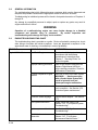
UNSCHEDULED MAINTENANCE
Unscheduled maintenance events include but are not limited to:
PROPELLER STRIKES
A propeller strike is: (1) any incident, whether or not the engine is operating, that requires
repair to the propeller other than minor dressing of the blades or (2) any incident while the
engine is operating in which the propeller makes contact with any object that results in a
loss of engine RPM. Propeller strikes against the ground or any object, can cause engine
and component damage even though the propeller may continue to rotate. This damage
can result in catastrophic engine failure.
A. PROPELLER STRIKE INSPECTIONS.
Following any propeller strike a complete engine disassembly and inspection is
mandatory and must be accomplished prior to further operation. Inspect all engine
accessories in accordance with the manufacturer's instructions. In addition to the
engine component inspection requirements set forth in the appropriate overhaul
manual, pay particular attention to the following areas while performing the
specified non-destructive testing:
1. Crankshaft surfaces forward of the front main bearing journal. These surfaces
must be free of sludge, paint or any other substance that could mask reliable
magnetic particle inspection indications.
2. Forward crankcase bearing support and adjacent structure.
NOTE:. . . In addition to any part that is damaged, TCM recommends for counterweight
equipped engines, replacement of all counterweight pins, bushings, end plates and snap
rings regardless of their condition.
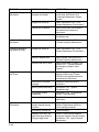
B. MINOR FOREIGN OBJECT DAMAGE (FOD) INSPECTION.
For instances where the propeller is damaged by a small foreign object during
operation, such as a small stone, inspection and repair must be accomplished in
accordance with the propeller manufacturer's published instructions. Any time
foreign object damage requires propeller removal for repairs other than minor
dressing of the blades, the incident is considered a propeller strike and must be
inspected as outlined in paragraph A above.
HYDRAULIC LOCK
GENERAL INFORMATION
Hydraulic lock is defined as a condition in which a volume of liquid, equal to or greater
than the clearance volume of the combustion chamber, is drawn into the cylinder during
starting. This liquid, being incompressible, restricts piston travel during the compression
stroke. Damage only occurs after the preceding cylinder or cylinders in the firing order
have fired, thereby providing the required force to drive the piston of the fluid filled cylinder
through the compression stroke.
Most hydraulic lock events in horizontally opposed aircraft engines are due to fuel
accumulation in the induction system and/or cylinder assembly. Over priming prior to or
during engine starting will allow fuel to accumulate in the induction system or cylinder
faster than the system drains can evacuate it. Other causes of hydraulic lock can be
attributed to:
1. Restricted or clogged induction system or cylinder drain(s).
2. Extended operation of the electric boost pump:
a. During failed engine start.
5-11
b. Following loss of power during ground operation.
c. Following momentary engine shutdown.
d. During single engine operation for training purposes on twin engine aircraft.
3. Over priming and attempting engine start with the aircraft parked on an incline that
negates the effective operation of the drain system.
4. A failure to drain oil from cylinders that have been preserved.
Damage from a hydraulic lock can be extensive. Engine components such as connecting
rods, cylinder assemblies, pistons, piston pins, crankcase and crankshaft can be
damaged due to the extreme stress.
WARNING
Over priming can cause a flooded intake resulting in a "hydraulic lock" event and
subsequent engine malfunction or failure. If you over prime, or flood your engine,
make certain that all fuel has drained from the intake manifold and/or cylinder prior
to attempting engine starting.
INSPECTION PROCEDURES FOR SUSPECTED HYDRAULIC LOCK.
In the event of a suspected hydraulic lock, perform the following inspection:
1. Remove all cylinders and connecting rods in accordance with the applicable TCM
Overhaul Manual. Inspect the connecting rods in accordance with applicable TCM
Overhaul Manual.
2. If all rods meet the criteria specified by TCM, reassemble the engine in accordance
with the overhaul manual.
3. If any connecting rod does not meet TCM acceptance criteria, remove and
disassemble the engine to allow inspection of the crankcase and crankshaft in
accordance with the applicable TCM Overhaul Manual. Replace any part that does
not meet Overhaul Manual inspection criteria.
Replace each non-conforming
connecting rod and its associated piston, piston pin and cylinder assembly.
NOTE: . . Any parts that require replacement must be destroyed to prevent future installation.
4. Reassemble the engine in accordance with the applicable TCM Overhaul Manual and
return the aircraft to service.
ENGINE OVERSPEED INSPECTION
Engine operation at speeds in excess of rated RPM limitations can cause damage to the
engine and can result in subsequent engine failure.
If an engine overspeed occurs determine the cause for overspeed and correct it. The
airframe manufacturer's instructions on engine and propeller overspeed must also be
referenced and followed.
If an engine overspeed occurs comply with the following procedures:
RPM TO 3000
1. Less than one minute - No action required
2. More than one minute - Proceed as follows:
a) Drain oil through a fine mesh screen and inspect for debris.
b) Remove oil filter and inspect filter element for debris.
5-12
c) Remove and inspect inside of rocker covers for debris. Inspect valve stem
(keeper grooves) and valve keepers for condition, security and proper
installation. Inspect valve springs, rocker arms, spring retainers, rotocoils,
pushrods, etc.
d) Perform a borescope inspection on all cylinders.
e) If no discrepancies are noted, re-service engine, perform operational inspection
and correct any discrepancies noted prior to returning the engine to service.
f)
If discrepancies are found a decision must be made, based on the evidence, as
to the extent of the corrective action required.
RPM TO 3300
1. In addition to action required for "B" above proceed as follows:
a) Remove all cylinder assemblies including rods and pistons.
b) Clean, inspect, repair or replace all components removed from the engine in
accordance with the manufacturer's current overhaul manual. Using new
connecting rod bolts and nuts, reassemble, service and test the engine in
accordance with the manufacturer's current overhaul manual.
c) After five and ten hours of engine operation remove oil filter and inspect filter
element for debris.
RPM EXCEEDING 3300
1. Remove engine and clearly identify "Removal For Overspeed".
2. Engine and accessories must be completely overhauled in accordance with the
respective manufacturer's current overhaul instructions or replaced with certified
airworthy components.
LIGHTNING STRIKE
It is impossible to assess internal damage that may result from a lightning strike. A
complete disassembly and inspection of the engine must be accomplished in accordance
with the manufacturer's current overhaul manual.
CONTAMINATED FUEL INCORRECT FUEL GRADE
If the aircraft is inadvertently serviced with the wrong grade of fuel or jet fuel the fuel must be
completely drained and the tank properly serviced.
Any engine operated on fuel of lower grade than approved for the engine or jet fuel must be
completely disassembled, cleaned, inspected, repaired, reassembled and tested in
accordance with the manufacturer's current overhaul manual.
5-13
5-8
GENERAL INFORMATION
The troubleshooting chart which follows discusses symptoms which can be diagnosed and
interprets the probable causes and the appropriate corrective actions to be taken.
Troubleshooting for individual systems will be found in that particular section of Chapters 11
through 22.
Any attempt by unqualified personnel to adjust, repair or replace any parts, may result in
engine malfunction or failure.
WARNING
Operation of a malfunctioning engine can cause further damage to a disabled
component and possible injury to personnel.
By careful inspection and
troubleshooting such damage and injury can be avoided.
5-9
ENGINE TROUBLESHOOTING CHART
This troubleshooting chart is provided as a guide. Review all probable causes given, check
other listings of troubles with similar symptoms. Items are presented in sequence of the
approximate ease of checking, not necessarily in order of probability.
TROUBLE
PROBABLE CAUSE
CORRECTION
Engine Will Not Start
Fuel Tank Empty
Service aircraft fuel system in
accordance with the airframe
manufacturer's instructions See
Chapter 7, "Servicing Fluids," for
correct fuel grade.
Improper starting procedure
Refer to the airframe manufacturer's
Airplane Flight Manual (AFM) for
engine starting procedures. Check for
performance of each item.
Cylinder overprimed. Engine
flooded.
Allow fuel to drain from intake system.
Induction system leak
Torque or replace loose or damaged
hose connection. See Section 14-5,
"Induction System maintenance."
Excessive Starter slippage
Replace starter adapter. See Section
17-5.
Fuel system malfunction
Isolate cause and correct. See
Section 13-4, "Fuel Injection System
Troubleshooting."
Ignition system malfunction
See Section 12-5, "Ignition
Troubleshooting."
Manifold valve vent
obstruction
Repair or replace manifold valve. See
Section 13-5, "Fuel System
Maintenance 'Manifold Valve.' "
5-14
WARNING . . . Starting an engine
with a flooded intake system will
result in hydraulic lock and
subsequent engine malfunction.
TROUBLE
PROBABLE CAUSE
CORRECTION
Engine Will Not Run At
Idling Speed
Fuel injection system
improperly adjusted
See Section 13-4, "Fuel Injection
System Troubleshooting."
Air leak in intake manifold
Torque loose connection or replace
damaged part. See Section 14-5,
"Induction System Maintenance."
Fuel injection system
improperly adjusted
See Section 13-4, "Fuel Injection
System Troubleshooting."
Mixture levers set for
improper mixture
Adjust the manual mixture control in
accordance with the airframe
manufacturer's Airplane Flight Manual
(AFM).
Fouled Spark Plugs
Remove, clean and adjust gaps. See
Section 12-6, "Ignition System
Maintenance 'Spark Plugs."
Hydraulic lifters fouled
Remove and clean lifters. Inspect and
clean oil filter at more frequent
intervals. See Section 20-6, "Cylinder
Assembly Maintenance 'Hydraulic
Valve Tappets."
Burned or warped exhaust
valves, worn seat, scored
valve guides
Repair cylinder. See Section 20-6,
"Cylinder Assembly Maintenance."
Improper manual leaning
procedure
Refer to the airframe manufacturer's
Airplane Flight Manual (AFM) for
engine operating instructions.
Fuel injection system
maladjusted
See Section 13-4, "Fuel Injection
System Troubleshooting."
Restrictions in air intake
passages
Check passages and remove
restrictions.
Improper manual leaning of
fuel/Air mixture
See the airframe manufacturer's
Airplane Flight Manual (AFM) for
correct leaning procedure.
Rough Idling
Engine Runs Too Lean At
Cruising Power
Engine Runs Too Rich At
Cruising Power
Engine Runs Too Lean Or Fuel injection system
maladjusted
Too Rich At Throttle
Setting Other Than Cruise
See Section 13-4, "Fuel Injection
System Troubleshooting."
Continuous Fouling Of
Spark Plugs
Replace rings. Replace cylinder if
damaged. See Section 20-6,
"Cylinder Assembly Maintenance."
Hone cylinder walls, replace rings.
See Section 20-6, "Cylinder
Assembly Maintenance."
Piston rings excessively worn
or broken
Piston rings are not seated
5-15
TROUBLE
PROBABLE CAUSE
CORRECTION
Engine Runs Rough At
High Speed
Loose mounting bolts or
damaged mount pads
Torque mounting bolts. Replace
mount pads. See Section 21-5,
"Crankcase Maintenance 'Engine
Mounts.' "
Plugged fuel nozzle jet
Clean. See Section 13-5, "Fuel
System Maintenance 'Fuel Nozzles.' "
Propeller out of balance
Remove and repair in accordance
with airframe manufacturer's
instructions.
Ignition system malfunction
See Section 12-5, "Ignition
Troubleshooting."
Continuous Missing At
High Speed
Broken valve spring
Replace, See Section 20-6,
"Cylinder Assembly Maintenance."
Continuous Missing At
High Speed (Cont’d)
Plugged fuel nozzle jet
Clean. See Section 13-5, "Fuel
System Maintenance 'Fuel Nozzles.' "
Burned or warped valve
Repair cylinder. See Section 20-6,
"Cylinder Assembly Maintenance."
Hydraulic lifter dirty or worn
Remove and clean or replace. See
Section 20-6, "Cylinder Assembly
Maintenance 'Hydraulic Valve
Tappets.' "
Throttle not full open
Check and adjust linkage. See
Rigging of Mixture and Throttle
Controls in the applicable airframe
manufacturer's instructions.
Restrictions in air intake
passages
Inspect air intake and remove
restrictions.
Ignition system malfunction
See Section 12-5, "Ignition
Troubleshooting."
Fuel injection system
maladjusted
See Section 13-4, "Fuel Injection
System Troubleshooting."
Exhaust system gas leakage
See the airframe manufacturer's
instructions.
Lean fuel/air mixture due to
improper manual leaning
procedure
See the airframe manufacturer's
Airplane Flight Manual (AFM) for
correct leaning procedure.
Dirt between cylinder fins
Clean thoroughly.
Magnetos out of time. No
appreciable drop detected
during pre-flight check.
Re-time, Check internal magneto
timing and magnetos timing to engine.
See Section 12-6, Ignition System
Maintenance.
Sluggish Operation And
Low Power
High Cylinder Head
Temperature
5-16
TROUBLE
PROBABLE CAUSE
CORRECTION
High Cylinder Head
Temperature (Cont’d)
Exhaust system gas leakage
Locate and correct in accordance with
the airframe manufacturer's
instructions.
Engine compartment cooling
baffles in poor condition.
Repair or replace in accordance with
the airframe manufacturer’s
instructions.
Exhaust valve leaking
Repair cylinder. See Section 20-6,
"Cylinder Assembly Maintenance."
At front of engine; damaged
crankshaft oil seal
Replace. See Section 22-5, "Engine
Drive Train Maintenance 'Crankshaft
Nose Oil Seal.' "
Around plugs fittings and
gaskets due to looseness or
damage
Torque or replace. See the applicable
disassembly, reassembly portions of
the L/TSIO-360 Series Overhaul
Manual, Form X30596A, for correct
torque values.
Piston rings excessively worn
Repair cylinder. See Section 20-6,
"Cylinder Assembly Maintenance."
Valve faces and seats worn
Repair cylinder. See Section 20-6,
"Cylinder Assembly Maintenance."
Excessively worn cylinder
walls
Replace cylinder & piston rings. See
Section 20-6, "Cylinder Assembly
Maintenance."
Slow Engine Acceleration
On A Hot Day
Mixture too rich
Momentarily pull mixture control back
until engine acceleration picks up.
Engine Will Not Stop At
Idle Cut-Off
Fuel manifold valve not
seating properly
Repair or replace fuel manifold valve.
See Section 13-5, "Fuel System
Maintenance 'Fuel Manifold Valve.' "
Climbing to Altitude Fuel
Flow Fluctuates
Fuel Vaporization, Fuel
mixture too rich
Operate fuel boost pump in
accordance with the airframe
manufacturer's Airplane Flight Manual
(AFM).
Low Fuel Pressure
Incorrect fuel pump
adjustment and operation
Check and adjust in accordance with
Chapter 23. Replace malfunctioning
pumps. See Section 13-5, "Fuel
System Maintenance 'Fuel Pump.' "
Malfunctioning fuel pump
relief valve
Replace fuel pump. See Section 13-5,
"Fuel System Maintenance’ Fuel
Pump.' "
Malfunctioning relief valve
operation in fuel pump
Replace fuel pump. See Section 13-5,
"Fuel System Maintenance’ Fuel
Pump.' "
Restricted re-circulation
passage in fuel pump
Replace fuel pump. See Section 13-5,
"Fuel System Maintenance’ Fuel
Pump.' "
Oil Leaks
Low Compression
High Fuel Pressure
5-17
TROUBLE
Fluctuating Fuel Pressure
Engine Has Poor
Acceleration
Engine Runs Rough At
Speeds Above Idle
Engine Lacks Power
Reduction in Maximum
Manifold Pressure
5-18
PROBABLE CAUSE
CORRECTION
Incorrect fuel pump
adjustment and operation
Check and adjust in accordance with
Chapter 23. Replace malfunctioning
pumps. See Section 13-5, "Fuel
System Maintenance 'Fuel Pump.' "
Fuel gage line leak or air in
gage line
Drain gage line and torque
connections in accordance with the
airframe manufacturer's instructions.
Vapor in fuel system,
excessive fuel temperature
Normally, operating the auxiliary
pump will clear system. Operate boost
pump in accordance with the airframe
manufacturer's Airplane Flight Manual
(AFM).
Idle mixture too lean
(Check RPM Rise, Idle Cutoff).,
Readjust idle mixture in accordance
with Chapter 23, "Fuel System
Adjustment."
Incorrect fuel-air mixture,
worn control linkage, or
restricted air cleaner
Torque loose connections, replace
worn elements of linkage. Service air
cleaner in accordance with airframe
manufacturer's instructions.
Malfunctioning ignition
system
Check ignition cables and
connections. Replace malfunctioning
spark plugs. See Section 12-4,
"Ignition System Inspection."
Improper fuel-air mixture
Check fuel manifold connections for
leaks. Torque loose connections.
Check fuel control and linkage for
setting and adjustment. Check fuel
filters and screens for dirt. Check for
proper fuel pump pressure, and
replace pump if malfunctioning. See
Section 13-5, "Fuel System
Maintenance."
Restricted fuel nozzle jet
Remove and clean all nozzle jets.
See Section 13-5, "Fuel System
Maintenance 'Fuel Nozzles.' "
Ignition system and spark
plugs malfunctioning
Clean and re-gap spark plugs. Check
ignition cables for wear. Replace
malfunctioning components. See
Section 12-6, "Ignition System
Maintenance."
Incorrectly adjusted throttle
control, "sticky" linkage or
dirty air cleaner
Check movement of linkage by
moving control from idle to full throttle.
Make proper adjustments and replace
worn components. Service air cleaner
in accordance with the airframe
manufacturer's instructions.
TROUBLE
Low Oil Pressure
Indication On Engine
Gage
Low Oil Pressure
Indication On Engine
Gage(cont'd)
PROBABLE CAUSE
CORRECTION
Malfunctioning ignition
system component
Inspect spark plugs for fouled
electrodes, heavy carbon deposits,
erosion of electrodes, improperly
adjusted electrode gaps, and cracked
porcelains. Test plugs for regular
firing under pressure. Replace
damaged or misfiring plugs. Gap
spark plugs to spark plug
manufacturer's specifications. See
Section 12-6, "Ignition System
Maintenance 'Spark Plugs.'
Loose or damaged intake
manifold
Inspect entire manifold system for
possible leakage at connections.
Replace damaged components,
torque all connections and clamps.
See Section 14-5, "Induction System
Maintenance."
Fuel nozzles malfunctioning
Check for restricted nozzle jets, lines
and clean or replace as necessary.
See Section 13-5, "Fuel System
Maintenance 'Fuel Nozzles.'
Malfunctioning Turbocharger
wastegate or exhaust system
See Section 11-8, "Exhaust System
Troubleshooting ."
Insufficient oil in oil sump, oil
dilution or using improper
grade oil for prevailing
ambient temperature
Add oil, or change oil to proper
viscosity. See Chapter 7, "Servicing
Fluids.' "
High oil temperature
Malfunctioning oil temperature control
valve in oil cooler; oil cooler
restriction. Replace valve or clean oil
cooler. See Section 18-5, "Oil
Cooler."
Leaking, damaged or loose
oil line connections Restricted screen or filter
Check for restricted lines, loose
connections, and for partially plugged
oil filter or screens. Clean parts,
torque connections, and replace
malfunctioning parts. See Section 185, "Oil Pump," for filter replacement.
Oil pressure gage
malfunction
Check oil pressure gage calibration in
accordance with the airframe
manufacturer's instructions.
Engine oil pressure
maladjusted
Adjust oil pressure in accordance with
Chapter 23, "Oil Pressure
Adjustment."
Low oil supply. Oil viscosity
too low
Replenish. Drain and refill with
correct seasonal weight. See Chapter
7, "Servicing Fluids."
5-19
TROUBLE
High Oil Temperature
Indication
5-20
PROBABLE CAUSE
CORRECTION
Malfunctioning oil pump
Replace oil pump. See Section 18-5,
"Oil Pump."
Weak or broken oil pressure
relief valve spring
Replace spring. Adjust pressure to
30-60 pounds per square inch in
accordance with Chapter 23, "Oil
Pressure Adjustment."
Prolonged ground operation
Limit ground operation to a minimum.
Malfunctioning gage or bulb
unit
Check wiring. Check bulb unit. Check
gage. Replace malfunctioning parts in
accordance with the airframe
manufacturer's instructions.
CHAPTER 6
Unpacking, Deinhibiting, Installation
and Testing
SECTION
PAGE
6-1
General ................................................................................................................... 6-2
6-2
Unpacking............................................................................................................... 6-2
6-3
Ground Handling .................................................................................................... 6-2
6-4
Crating and Shipping .............................................................................................. 6-2
6-5
Preparation for Service........................................................................................... 6-3
6-6
Engine Installation Instructions............................................................................... 6-4
6-7
Engine Pre-oiling .................................................................................................. 6-12
6-8
Preflight and Run-Up ............................................................................................ 6-12
6-9
Flight Testing ........................................................................................................ 6-13
FIGURE
6-1
INDEX
Installation Drawing L/TSIO-360-RB ...................................................................... 6-6
Installation Drawing L/TSIO-360-RB (continued)................................................... 6-7
Installation Drawing L/TSIO-360-RB (continued)................................................... 6-8
Installation Drawing L/TSIO-360-RB (continued)................................................... 6-9
6-1
INTENTIONALLY
LEFT
BLANK
6-2
6-1
GENERAL
Technicians involved with engine preparation and installation into the airframe must possess
a detailed knowledge of safe procedures used in engine servicing and the operation of
ground support equipment.
The engine must have a detailed visual inspection prior to installation in the airframe.
6-2
UNPACKING
Packaging Category "A" (Cardboard Container)
1. Cut steel banding straps securing the container. (Use caution as straps may spring
loose when cut).
2. Remove the staples from the base of the cardboard cover.
3. Lift cardboard cover vertically and remove.
4. Attach a hoist to the engine lifting eye, located at the top of the crankcase backbone.
Take up slack on the hoist, then cut the steel banding straps holding the engine to the
base. (Use caution as straps may spring loose when cut.) Lift the engine vertically and
install on a transportation stand or dolly.
CAUTION . . . Do not allow chains to become entangled on engine or its hardware.
Packaging Category "B" (Wooden Container)
1. Remove the (4) four lag screws attaching the wooden cover to the base.
2. Lift the wooden cover vertically and remove.
3. Open the moisture proof plastic bag.
4. Attach a hoist to the engine lifting eye located at the top of the crankcase backbone.
Take up slack on the hoist, prior to loosening the engine mount bolts; then remove the
bolts from the shipping shock mounts. Lift the engine vertically and install on a
transportation stand or dolly.
CAUTION . . . Do not allow chains to become entangled on engine or its hardware.
6-3
GROUND HANDLING
After engine is removed from container (attached to hoist) proceed with care. Do not let
engine front, rear, sides or bottom come in contact with any obstructions as the extreme
weight may cause damage to the engine or components. If contact has occurred, inspect
for obvious or consequential damage.
6-4
CRATING AND SHIPPING
Category"A" (cardboard container). Lower engine onto container base and attach with
metal banding straps. Install and attach container cover.
Category "B" (wooden container). Lower engine onto container base. Attach engine using
shock mounts and bolts. Cover engine with plastic bag. Install and attach container cover to
base.
6-3
6-5
PREPARATION FOR SERVICE
If the engine is not to be installed within five (5) days after removing shipping plugs, it must
be represerved in accordance with procedures listed in Chapter 8.
If the engine is to be installed within five (5) days after unpacking, remove the shipping plugs
installed in the lower spark plug holes and turn the crankshaft through at least two complete
revolutions in order to remove the cylinder preservation oil from the cylinder. Remove the
shipping plugs installed in the upper spark plug holes and inspect the cylinder bore with a
borescope for rust or contamination. Contact your Teledyne Continental Motors Distributor if
any abnormal condition is noted.
Apply Champion® thread lubricant to spark plugs in accordance with the manufacturer's
instructions (see Chapter 3). Install the spark plugs and torque to 300-360 in. lbs.Install the
upper spark plugs finger tight.
CAUTION . . . During installation of propeller governor in accordance with the airframe
manufacturer's instructions ,insure that the governor gear splines align properly with the
camshaft governor drive gear and that the governor is fully seated to the crankcase prior to
installing the attaching hardware. This will eliminate the possibility of misalignment forcing
the governor bevel gear over the camshaft governor drive gear. Also insure that the proper
gasket is used and lubrication holes are properly aligned.
WARNING
Oil pressure is applied to the face of the accessory drive pads. If gasket, accessory
or cover is not properly installed and hardware is not properly torqued oil leakage will
occur.
CAUTION . . . When a test club or fixed pitch propeller is used for testing purposes the
governor pad cover must have an internal grooved surface to allow the circulating oil to
lubricate the front main bearing. The governor pad cover is not needed if a propeller
governor is installed.
WARNING
Do not connect the ignition harness to the spark plugs until the propeller installation
is completed. Failure to comply could result in bodily injury when the propeller is
rotated during installation.
NOTE . . . Remove all protective plugs from the following locations: exhaust outlets,
crankshaft flange and fuel pump fittings.
NOTE . . . Drain preservative oil from sump. Engines that have a complete set of
overhauled or new cylinders and new piston rings installed must be serviced with clean
Engine Break-In and Preservation oil conforming with MIL-C-6529 TYPE II until it has been
determined that the engine oil consumption has stabilized (approximately 25 hours of
operation.) Thereafter, the engine must be serviced with clean ashless dispersant oil. See
Section 7-2, "Approved Ashless Dispersant Oils."
6-4
6-6
ENGINE INSTALLATION INSTRUCTIONS (See Figures 6-1)
CAUTION . . . The engine must be hoisted using the lifting eye brackets only.
WARNING
The aircraft fuel tanks and lines must be purged to remove all contamination prior to
installation of the main fuel inlet line to the fuel pump. Failure to comply can cause
erratic fuel injection system operation and damage to its components.
Install the engine and make airframe to engine connections in accordance with the airframe
manufacturer's instructions.
Install all airframe manufacturer required components including cooling baffles, hoses,
fittings, brackets and ground straps in accordance with the airframe manufacturer's
installation instructions.
WARNING
Do not connect the ignition harness to the spark plugs until the propeller installation
is completed. Failure to comply could result in bodily injury when the propeller is
rotated during installation.
6-5
FIGURE 6-1. INSTALLATION DRAWING
6-6
FIGURE 6-1. INSTALLATION DRAWING (cont'd)
6-7
FIGURE 6-1. INSTALLATION DRAWING (cont'd)
6-8
FIGURE 6-1. INSTALLATION DRAWING (cont'd)
6-9
6-7
ENGINE PRE-OILING
It is important that all engine internal moving parts be properly lubricated before initial
running of engine. Pre-oil engine prior to initial engine operation according to the following
procedure:
1. Pre-oiling may be accomplished using a bladder type pressure pot capable of holding at
least (1) gallon of clean aviation engine oil with an output pressure of 50 not to exceed
60 psi. See Section 7-2, "Approved Ashless Dispersant Oils," for proper type of oil to
use. See Section 1-10, "Operating Limits," for proper seasonal oil grade.
2. Remove rocker box covers from cylinders. Connect pre-oiler supply hose to engine oil
pressure gage line connection (fitting). Open pre-oiler valve and watch cylinder rocker
areas for indication of oil flow. Some engines may take as long as twenty (20) minutes
for oil indication depending on oil temperature.
3. After oil flow has been confirmed, re-install rocker covers using new gaskets, torque
rocker cover screws to limit specified in the L/TSIO-360 Overhaul Manual, Form OH-08.
Close valve on pre-oiler. Disconnect pre-oiler supply hose and cap or re-install engine
oil pressure gage line on pressure gage line connection (fitting) as applicable.
4. Check engine oil gage rod (dipstick) and service to correct capacity. Engine is now
ready for initial run-up and test.
CAUTION . . . Recheck the oil level in the sump. Do not operate the engine with more or
less than the oil sump capacity. See Sections 1-10, "Operating Limits" and 7-1, "Servicing
Oil," for correct grade oil, sump capacity and servicing points.
If the magneto attaching nuts were loosened or the magnetos rotated during engine
installation, magneto to engine timing must be adjusted to specification prior to starting. See
Section 12-5 Ignition System Maintenance of this manual.
Apply Champion® thread lubricant to spark plugs in accordance with the manufacturer's
instructions (see Chapter 3). Install the upper spark plugs and torque to 300-360 inch
pounds.
Install the ignition harness "B" nuts on the spark plugs. The nuts are stamped with a
position identifier, i.e. "1t" which means the top spark plug of the number one cylinder.
6-8
PREFLIGHT AND RUN-UP
NOTE . . . Engines that have a complete set of overhauled or new cylinders and new piston
rings installed must be serviced with Engine Break-In and Preservation oil conforming with
MIL-C-6529 TYPE II until it has been determined that the engine oil consumption has
stabilized (approximately 25 hours of operation.)
Thereafter, the engine must be serviced with the appropriate grade (depending on ambient
temperature) of ashless dispersant oil. See Section 7-2, "Approved Ashless Dispersant
Oils."
Start the engine in accordance with the procedures in the airframe manufacturer's Airplane
Flight Manual (AFM).
High power ground operation resulting in cylinder and oil temperatures exceeding normal
operating limits can be detrimental to cylinders, pistons, valves and rings.
The fuel system must be adjusted prior to flight in accordance with this manual. See Chapter
23, "Fuel System Adjustment."
An operational inspection in accordance with section 5-3 of this manual must be performed
prior to releasing the aircraft for test flight. The operational inspection must be performed to
insure that no induction system, exhaust system, oil system, fuel system leaks or any other
6-10
discrepancies exist. After the operational inspection a test flight is required to insure that the
engine and aircraft meet all of the manufacturer's performance and operational
specifications prior to releasing the aircraft for normal service.
WARNING
Although the engine fuel system was adjusted at engine test, the fuel system must be
checked and adjusted in accordance with Chapter 23 "Fuel System Adjustment," of
this manual and current TCM service documents when the engine is first installed
into the airframe and at 100 hour intervals to insure proper operation. All
discrepancies must be corrected prior to test flight.
6-9
FLIGHT TESTING
CAUTION . . . Adhere to engine operating limits published in this Manual and the Pilot's
Operating Handbook/Airplane Flight Manual during test flight.
Ambient air and engine operating temperatures are of major concern during this test flight.
Accomplish a normal pre-flight run-up in accordance with the airframe manufacturer's Pilot's
Operating Handbook/Airplane Flight Manual. Conduct a normal take-off with full power and
monitor the fuel flow, RPM, oil pressure, cylinder head temperatures and oil temperatures.
Reduce to climb power in accordance with the flight manual and maintain a shallow climb
attitude to gain optimum airspeed and cooling. Rich mixture should be used for all
operations except leaning for cruise economy. Leaning operations must be performed in
accordance with the airframe manufacturer's Pilot's Operating Handbook/Airplane Flight
Manual.
Level flight cruise should be at 75% power with best power or richer mixture for the first hour
of operation. During the second hour, alternate power settings between 65% and 75%
power with the appropriate best power mixture settings. The best power mixture setting is
100°F to 150°F rich of peak exhaust gas temperature.
The descent should be made at low cruise power settings with careful monitoring of engine
pressures and temperatures.
Any abnormal conditions detected during test flight must be corrected and any final
adjustments must be accomplished prior to releasing the aircraft for normal service.
6-11
INTENTIONALLY
LEFT
BLANK
6-12
CHAPTER 7
SERVICING FLUIDS
SECTION
PAGE
7-1
Servicing, Oil........................................................................................................... 7-2
7-2
Approved Engine Lubricating Oils.......................................................................... 7-3
7-3
Fuel ......................................................................................................................... 7-3
7-4
Oil Filter Element Inspection .................................................................................. 7-4
7-5
Spectrographic Oil Analysis ................................................................................... 7-4
FIGURE
7-1
PAGE
Oil Servicing Points ................................................................................................ 7-2
7-1
7-1
SERVICING OIL
CAUTION . . . Some funnel-type quart oil containers incorporate a styrofoam or aluminum
seal. Remove this seal from the container and discard it before adding oil to the engine. If
the seal falls into the engine, engine damage and possible failure can result.
The oil system must be serviced to capacity with the oil grades specified.
A certain amount of oil consumption is normal. If excessive consumption or any abrupt
change in rate of consumption is detected, this condition must be corrected before further
flight.
Maintain the engine compartment, nacelle and the fuselage adjacent to the nacelle in a
clean condition in order that an oil leak can be detected and corrected before further flight.
WARNING
Engine operation with no oil or severely reduced oil levels will cause engine
malfunction or failure.
CAUTION . . . Petroleum base aviation engine oil is flammable and must be stored in a well
ventilated area away from any heat source.
FIGURE 7-1. OIL SERVICING POINTS
7-2
7-2
APPROVED ASHLESS DISPERSANT OILS :
BP Oil Corporation
Castrol
Castrol Limited (Australia)
Chevron U.S.A., Inc.
Continental Oil
Delta Petroleum Company
Exxon Company, U.S.A.
Gulf Oil Company
Mobil Oil Company
NYCO S.A.
Pennzoil Company
Phillips Petroleum Company
Phillips Petroleum Company
Quaker State Oil & Refining Company
Red Ram Limited (Canada)
Shell Australia
Shell Canada Limited
Shell Oil Company
Sinclair Oil Company
Texaco Inc.
Total France
Union Oil Company of California
BP Aero Oil
Castrol Aero AD Oil
Castrol Aero AD Oil
Chevron Aero Oil
Conco Aero S
Delta Avoil Oil
Exxon Aviation Oil EE
Gulfpride Aviation AD
Mobil Aero Oil
TURBONYCOIL 3570
Pennzoil Aircraft Engine Oil
Phillips 66 Aviation Oil, Type A
X/C Aviation Multiviscosity Oil
SAE 20W50, SAE 20W60
Quaker State AD Aviation Engine Oil
Red Ram X/C Aviation Oil 20W50
Aeroshell (R) W
Aeroshell Oil W, Aeroshell Oil W 15W50
Anti-Wear Formulation Aeroshell Oil W 15W50
Aeroshell Oil W, Aeroshell Oil W 15W50
Anti-Wear Formulation Aeroshell Oil W 15W15
Sinclair Avoil
Texaco Aircraft Engine Oil - Premium AD
Total Aero DM 15W50
Union Aircraft Engine Oil HD
APPROVED MINERAL OIL:
MIL-C-6529 TYPE II
7-3
FUEL
Aviation Minimum Grade
100LL (Blue) or 100 (Green)
WARNING
The use of lower octane rated fuel or jet fuel will result in damage or destruction of an
engine the first time high power is applied. This would most likely occur on takeoff.
If the aircraft is inadvertently serviced with the wrong grade of fuel or jet fuel the fuel
must be completely drained and the tank properly serviced.
For aircraft fueling procedure, see the airframe manufacturer's instructions.
7-3
7-4
OIL FILTER ELEMENT INSPECTION
Inspect oil filter element at each oil and filter change even if oil analysis is being used. Filter
element inspection may identify internal engine wear that will not be identified through oil
analysis.
New, rebuilt, overhauled engines or engines that have had cylinders replaced will generally
exhibit noticeable amounts of normal wear material at the first and second oil and filter
change. The amount of material present should significantly decrease between the first and
second oil and filter change if the engine and or cylinders have been properly operated
during the break-in period.
As with oil analysis, oil filter element inspection provides maintenance personnel with
additional information on the wear characteristics of a specific engine. Sudden, unexplained
increases in concentration of wear material in a filter element should alert maintenance
personnel to investigate the source and cause of the material.
Material Identification:
Ferrous - attracts to magnet.
Aluminum - will "sizz" or bubble when placed in a 50 % solution of muriatic acid.
Bronze or Copper - will turn bright green when placed in nitric acid.
Carbon - will disintegrate when rubbed between index finger and thumb.
Sand - will not disintegrate when rubbed between two hard surfaces and will scratch glass
when pressure is applied.
Nickel - will not be magnetically attracted but looks similar to ferrous material.
Tin - will not be attracted magnetically. It looks similar to nickel but is soft and malleable.
7-5
SPECTROGRAPHIC OIL ANALYSIS
Spectrographic oil analysis has become popular with the owners and operators of general
aviation piston powered aircraft. This process was developed more than 35 years ago by
the railroads as a method of identifying wear characteristics in large diesel engines.
Eventually oil analysis was adopted by the military and then by commercial and general
aviation.
Engines are designed and manufactured using various materials and alloys. The engine
lubrication system is designed to provide either pressure or splash oil to areas of the engine
subjected to frictional loading. During normal operation these areas undergo minute,
continuous wear; sub-micronscopic material is released from these contact surfaces and are
suspended in the lubricating oil. Spectrographic oil analysis identifies these materials and
their level of concentration in parts per million (PPM).
There are two accepted methods of performing oil analysis: atomic absorption and atomic
emissions.
Atomic absorption will identify suspended wear material that is five micron in size or smaller,
while atomic emissions will identify suspended wear material that is ten micron in size or
smaller. Since engine oil analysis is used as a tool to establish engine wear trends and
deviations from the established norm, either method is acceptable; however, it is important
to realize the oil analysis program must utilize the same laboratory for all sample analysis.
Comparing an oil analysis report from a separate laboratory will have little meaning if each
laboratory uses a different analysis method.
7-4
7-5
SPECTROGRAPHIC OIL ANALYSIS (continued)
A proper spectrographic oil analysis program should begin with the first engine oil change.
Establishing a wear trend data base for an engine will require analysis of at least three oil
samples. As the engine accumulates operating time and additional oil samples are
analyzed, a definitive wear trend can be identified. Unexplained deviations from normal
wear trend patterns should be investigated using accepted, conventional inspection
methods.
Spectrographic oil analysis must be accomplished according to a set protocol to provide any
useful information. Even if done properly, spectrographic oil analysis will rarely provide any
prior indication of a fatigue type failure. A single spectrographic oil sample will usually not
provide a high level of useful information since there is no established wear trend data on
that specific engine for comparison.
Spectrographic oil analysis will assist in the identification of an internal engine problem. If
samples are properly taken at regular intervals, it should provide the owner / operator and oil
analysis technician with information relative to normal or abnormal wear that occurs during
the course of engine operation. Deviations from an established wear trend pattern should
alert the owner / operator and oil analysis technician to further investigate.
Limitations
Variations in operation, use and maintenance may be reflected in the parts per million
content reported. Deviations from standard or previously used sampling procedures may
result in variations to the parts per million content in the sample report.
General Procedures
To establish a data base for comparison and analysis, oil samples must be taken on a
regular schedule using the same sampling techniques and laboratory. The engine must
have been operated long enough to obtain normal operational temperatures and the oil
sample taken within 30 minutes after engine shut down. The tube or funnels used to drain
the oil from the sump must be clean and free of any foreign material or residue. If the oil
sample is taken from the oil as it drains from the sump, allow approximately 1/3 of the oil
drain prior to taking the sample. If the sample is taken via the oil filler or other location using
a sampling tube, it is critical the sample be taken from two or three inches above the bottom
of the oil sump, not from the bottom. Do not take an oil sample from the oil filter canister.
7-5
INTENTIONALLY
LEFT
BLANK
7-6
CHAPTER 8
ENGINE PRESERVATION AND STORAGE
Section
Page
8-1
General ................................................................................................................... 8-2
8-2
Engine Preservation ............................................................................................... 8-2
8-3
Temporary Storage................................................................................................. 8-2
8-4
Indefinite Storage ................................................................................................... 8-3
8-5
Indefinite Storage Inspection Procedures .............................................................. 8-4
8-6
Returning An Engine To Service............................................................................ 8-4
8-1
8-1
GENERAL
There is no practical procedure that will insure corrosion prevention on installed aircraft
engines. Susceptibility to corrosion is influenced by geographical location, season and
usage. The owner/operator is responsible to recognize the conditions that are conducive to
corrosion and take appropriate precautions.
8-2
ENGINE PRESERVATION
Corrosive attack can occur in engines that are flown only occasionally regardless of
geographical location. In coastal areas and areas of high humidity corrosive attack can
occur in as little as two days. The best method of reducing the likelihood of corrosive attack
is to fly the aircraft at least once every week for a minimum of one hour.
NOTE. . . Corrosive attack may reduce engine service life. Of primary concern are cylinders,
piston rings, valves, valve guides camshaft and lifters.
NOTE. . . See Precision Airmotive Corporation instructions for preservation of the fuel servo
unit.
The following procedure, if properly utilized, will aid in reducing the severity of corrosive
attack.
8-3
TEMPORARY STORAGE
Preparation for storage.
1. Remove oil sump drain plug and drain oil. Replace drain plug, torque and safety.
Remove oil filter. Install new oil filter torque and safety. Service engine to proper sump
capacity with oil conforming to MIL-C6529 Type II.
2. Perform a ground run-up. Perform a pre-flight inspection and correct any discrepancies.
Fly the aircraft for one hour at normal operation temperatures.
WARNING
To prevent possibility of serious bodily injury or death, before moving the propeller
accomplish the following:
a. Disconnect all spark plug leads.
b. Verify magneto switches are connected to magnetos, that they are in the
"OFF" Position and "P" leads are grounded.
c. Throttle position "CLOSED."
d. Mixture control "IDLE-CUT-OFF."
e. Set brakes and block aircraft wheels.
f. Insure that aircraft tie-downs are installed and verify that the cabin door latch
is open.
g. Do not stand within the arc of the propeller blades while turning the propeller.
3. After flight remove all spark plug leads and remove the top spark plugs. Protect the
ignition lead ends with AN-4060 Protectors. Using a common garden sprayer or
equivalent, spray atomized preservative oil that - meets MIL-P-46002, Grade 1, at room
temperature through upper spark plug hole of each cylinder with the piston at bottom
dead center position. Rotate crankshaft as opposite cylinders are sprayed. Stop
crankshaft with none of the pistons at top dead center.
4. Re-spray each cylinder. To thoroughly cover all surfaces of the cylinder interior move
the nozzle or spray gun from the top to the bottom of the cylinder.
5. Install top spark plugs but do not install spark plug leads.
8-2
6. Seal all engine openings exposed to the atmosphere using suitable plugs and covers.
7. Tag each propeller in a conspicuous place with the following notation on the tag: DO
NOT TURN PROPELLER - ENGINE PRESERVED PRESERVATION DATE
.
NOTE. . . If the engine is not returned to flyable status on or before the 90-day expiration, it must be
preserved in accordance with "Indefinite Storage" procedures in this chapter.
8-4
INDEFINITE STORAGE
PREPARATION FOR STORAGE
1. Remove oil sump drain plug and drain oil. Replace drain plug, torque and safety.
Remove oil filter. Install new oil filter torque and safety. Service engine to proper sump
capacity with oil conforming to MIL-C6529 Type II.
2. Perform a ground run-up. Perform a pre-flight inspection and correct any discrepancies.
Fly the aircraft for one hour at normal operation temperatures.
WARNING
To prevent possibility of serious bodily injury or death, before moving the
propeller accomplish the following:
a. Disconnect all spark plug leads.
b. Verify magneto switches are connected to magnetos, that they are in
the "OFF" Position and "P" leads are grounded.
c. Throttle position "CLOSED."
d. Mixture control "IDLE-CUT-OFF."
e. Set brakes and block aircraft wheels.
f. Insure that aircraft tie-downs are installed and verify that the cabin door
latch is open.
g. Do not stand within the arc of the propeller blades while turning the
propeller.
3. After flight remove all spark plug leads and remove the spark plugs. Protect the ignition
lead ends with AN-4060 Protectors. Install protective plugs P/N 22671 in bottom spark
plug holes. Using a common garden sprayer or equivalent, spray atomized preservative
oil that meets MIL-P-46002, Grade 1, at room temperature through upper spark plug
hole of each cylinder with the piston at bottom dead center position. Rotate crankshaft
as opposite cylinders are sprayed. Stop crankshaft with none of the pistons at top dead
center.
4. Re-spray each cylinder. To thoroughly cover all surfaces of the cylinder interior move
the nozzle or spray gun from the top to the bottom of the cylinder.
5. Install dehydrator plugs MS 27215-1 or -2 in each of the upper spark plug holes. Make
sure each plug is blue in color when installed.
6. Attach a red "REMOVE BEFORE FLIGHT" streamer to each bag of desiccant. Place a
bag of desiccant in the exhaust pipes and seal the openings.
7. Seal all engine openings exposed to the atmosphere using suitable plugs and covers.
8. Tag propeller in a conspicuous place with the following notation on the tag: DO NOT
TURN PROPELLER - ENGINE PRESERVED - PRESERVATION DATE
.
8-3
8-5
INDEFINITE STORAGE INSPECTION PROCEDURES
1. Aircraft prepared for indefinite storage must have the cylinder dehydrator plugs visually
inspected every 15 days. The plugs must be changed as soon as they indicate other
than a dark blue color. If the dehydrator plugs have changed color in one-half or more of
the cylinders, all desiccant material on the engine must be replaced.
2. The cylinder bores of all engines prepared for indefinite storage must be re-sprayed with
corrosion preventive mixture every 90 days.
8-6
RETURNING AN ENGINE TO SERVICE AFTER STORAGE
1. Remove seals and all desiccant bags.
2. Remove cylinder dehydrators and plugs or spark plugs from upper and lower spark plug
holes.
3. Remove oil sump drain plug and drain the corrosion preventive mixture. Replace drain
plug, torque and safety. Remove oil filter. Install new oil filter torque and safety.
Service the engine with oil in accordance with the manufacturer's instructions.
WARNING
To prevent possibility of serious bodily injury or death, before moving the propeller
accomplish the following:
a. Disconnect all spark plug leads.
b. Verify magneto switches are connected to magnetos, that they are in the
"OFF" Position and "P" leads are grounded.
c. Throttle position "CLOSED."
d. Mixture control "IDLE-CUT-OFF."
e. Set brakes and block aircraft wheels.
f. Insure that aircraft tie-downs are installed and verify that the cabin door latch
is open.
g. Do not stand within the arc of the propeller blades while turning the propeller.
4. Rotate propeller by hand several revolutions to remove preservative oil.
5. Service and install spark plugs and ignition leads in accordance with the manufacturer's
instructions.
6. Service engine and aircraft in accordance with the manufacturer's instructions.
7. Thoroughly clean the aircraft and engine. Perform visual inspection.
8. Correct any discrepancies.
9. Conduct a normal engine start.
10. Perform operational test in accordance with "Operational Inspection," Chapter 1,
Maintenance. .
11. Correct any discrepancies.
12. Perform a test flight in accordance with airframe manufacturer's instructions.
13. Correct any discrepancies prior to returning aircraft to service.
14. Change oil and filter after 25 hours of operation.
8-4
CHAPTER 9
STANDARD PRACTICES
SECTION
PAGE
9-1
General .............................................................................................................. 9-2
9-2
Lockwire Procedure ........................................................................................... 9-3
9-3
Tab Washer Procedure ...................................................................................... 9-5
9-4
Cotter Pin Procedure.......................................................................................... 9-5
9-5
Application Of Adhesives ................................................................................... 9-6
9-6
Installation Of Gaskets ....................................................................................... 9-6
FIGURE
PAGE
9-1
General Lockwire Procedure.............................................................................. 9-3
9-2
General Lockwire Patterns................................................................................ 9-4
9-3
Tab Washer Installation Procedure.................................................................... 9-5
9-4
General Cotter Pin Installation ........................................................................... 9-6
9-1
9-1
GENERAL
To facilitate and insure proper reinstallation, tag or mark all parts and hardware as they
are removed or disassembled.
Tag any unserviceable parts or units for investigation and possible repair. Take extreme
care to prevent foreign matter, lockwire, nuts, washers, dirt, etc., from entering the engine
on or off the aircraft. Make use of protective caps, plugs and covers to insure openings
are unexposed.
WARNING
Dust caps used to protect open lines must be installed OVER the tube ends and
NOT IN the tube ends. Flow through the lines will be blocked if lines are
inadvertently installed with the dust caps in the tube ends.
If anything is dropped into the engine work must be stopped immediately and the item
removed.
Insure all parts are thoroughly cleaned, properly protected from dust and corrosion and
properly stored until assembly .
Make sure replacement nonmetallic and metallic parts show no sign of storage
deterioration. Parts exceeding specified shelf life limitations must not be used.
9-2
9-2
LOCKWIRE PROCEDURE
Lockwiring is the securing together of two or more parts with lockwire which shall be
installed in such a manner that any tendency for a part to loosen will be counteracted by
additional tightening of the wire.
Wire shall be pulled taut while being twisted and caution must be exercised during the
twisting operation to keep the wire tight without over stressing. See Figure 9-1, "General
Lockwire Procedure" for steps in applying lockwire.
All lockwire utilized on TCM engines must conform to MS 20995 Condition A. Most bolts
utilized in TCM engines that require lockwiring will use .032 lock wire and require twisting
at a rate of 7 to 10 twists per inch. Lockwire shall be new at each application.
FIGURE 9-1. GENERAL LOCKWIRE PROCEDURE
9-3
9-3
LOCKWIRE PROCEDURE (cont'd)
Various examples of lockwiring are shown in Figure 9-2, "General Lockwire Patterns."
1. All items to be lockwired must be properly torqued. Applying torque that is above or
below specified limits to obtain alignment of the holes is not permitted.
2. Lockwire shall be installed in such a manner that the strand through the hole will have
a tendency to pull the in the tightening direction.
3. Insert half of the required length of lockwire through the first unit and bend around the
head of the unit. The direction of wraps and twist of strands shall be such that the
loop around the unit comes under the strand protruding from the hole so that the loop
will stay down and will not tend to slip up and leave a slack loop.
4. Twist the strands while taut until the twisted part is just short of a hole in the next unit.
The twisted portion should be within one-eighth (1/8) inch from the hole in either unit.
5. Insert the uppermost strand through the hole in the second unit and follow the rules in
paragraph three.
6. After lockwiring the last unit, continue twisting the wire to form a pigtail providing a
minimum of four twists to insure that the pigtail will not unravel. Cut off the excess
lockwire and bend the pigtail toward the part and against the bolt head flats. DO NOT
ALLOW THE PIGTAIL TO EXTEND ABOVE THE BOLT HEAD.
FIGURE 9-2. GENERAL LOCKWIRE PATTERNS
9-4
9-4
TAB WASHER PROCEDURE
Tab washers are installed by fitting a tab in a tab slot and bending the remaining tabs
firmly against the bolt or nut flat. Tab washers are used in various locations in TCM
engines and must not be reused after removal.
The tabs that are provided to be bent up against the head flats must be seated firmly, with
no scarring of the tabs. This provides proper locking of the unit and prevents tabs from
breaking off.
1.
Make certain that the holding tab is located in the tab hole or slot.
2.
Check the units to be secured and verify that they have been correctly torqued in
accordance with the applicable overhaul manual.
3.
Bend tabs against the head flats firmly by tapping them into place with a soft drift.
See Figure 9-3, "Tab Washer Installation Procedure."
FIGURE 9-3. TAB WASHER INSTALLATION PROCEDURE
9-5
COTTER PIN PROCEDURE
Cotter pins are installed by inserting the cotter pin through a hole in one part and slots in
the other part and spreading the exposed ends.
Cotter pins are not reusable and must be replaced with a new cotter pin after removal.
1. Torque the nut to the lower limit of the torque specification. If the slots in the nut do not
line up with one of the holes in the bolt, continue torquing until one does but do not
exceed the upper limit of the torque specification. Change the nut if necessary.
2. Insert the cotter pin with the head seated firmly in the slot of the nut. Bend the ends
over the flat on the nut and the end of the bolt, trimming the prong lengths as
necessary.
3. Seat the prongs firmly against the bolt and nut. See Figure 9-4, "General Cotter Pin
Installation."
CAUTION. . . Do not use side-cutting type pliers to bend the ends over, since the resulting
nick could weaken the pin and allow a portion to become detached.
9-5
FIGURE 9-4. GENERAL COTTER PIN INSTALLATION
9-6
APPLICATION OF ADHESIVES
Adhesives and sealants will be used as specified in this manual.
WARNING
The improper use of sealants and adhesives will cause engine malfunction or
failure.
Gasket Maker P/N 646942 must be applied in a thin even coat. Gasket Maker surfaces
must be clean and free of oil and grit.
NOTE. . . TCM general purpose primer 653160 must be used for surface preparation
before applying gasket maker at the engine nose seal area.
9-7
INSTALLATION OF GASKETS
All gaskets must be new and visually inspected prior to installation.
If the gasket shows any indication of gouges, nicks, cuts or bends discard it and obtain an
undamaged gasket.
Gasket surfaces must be clean and free of oils and grit. Apply a thin coat of TCM Gasket
Sealant #642188 to both sides of gasket where specified. Once gasket sealant has been
applied install gasket. Install assembly and evenly torque hardware.
WARNING
Gaskets and components must be properly positioned, hardware torqued and
safetied as required during assembly to prevent oil loss.
9-6
CHAPTER 10
ENGINE MAINTENANCE
10-1
GENERAL
During engine 50 and 100 hour inspections, if engine components must be remove and
replaced, refer to the applicable disassembly/reassembly instructions found in the TSIO360 Series Overhaul Manual, Form OH-08 as outlined in Maintenance Section of each
system.
NOTE . . . Engine operational inspection must be performed prior to any 50 or 100 hour
static inspections. See Section 5-3, “Operational Inspection.”
Compare recorded findings of operational inspection to Operating Limits Section 1-10
and information listed under applicable system 50 and 100 hour inspection of the following
chapters.
Corrections and adjustments will be found in the individual system chapters of this manual
under “Maintenance” and Chapter 23, “Post Maintenance Adjustment and Test.”
At the completion of all 50/100 hour inspection procedures, see Chapter 23 and perform
the post maintenance operational test.
WARNING
The figures depicted in this publication are for illustration purposes only. They are
not intended to be accurate detailed illustrations of any specific engine model, part
or equipment.
10-1
INTENTIONALLY
LEFT
BLANK
10-2
CHAPTER 11
EXHAUST SYSTEM
SECTION
PAGE
11-1
Exhaust System Description............................................................................. 11-2
11-2
Turbocharger Detailed Description.................................................................. 11-4
11-3
Exhaust By-pass Valve (Wastegate) Detailed Description............................ 11-5
11-4
Variable Absolute Pressure Controller (VAPC) Detailed Description .......... 11-6
11-5
Turbocharger Lubrication System ................................................................... 11-7
11-6
Exhaust System Inspection .............................................................................. 11-7
11-7
Exhaust System Troubleshooting.................................................................... 11-9
11-8
Exhaust System Maintenance......................................................................... 11-11
FIGURE
PAGE
11-1
Induction and Exhaust System Schematic ..................................................... 11-3
11-2
Basic Turbocharger ........................................................................................... 11-4
11-3
Turbocharger Sectional View............................................................................ 11-5
11-4
Wastegate............................................................................................................ 11-5
11-5
Variable Absolute Pressure Controller ............................................................ 11-6
11-6
Slipjoint Assembly ............................................................................................. 11-8
11-6
Multi-Segment "V" Band Clamp........................................................................ 11-8
11-1
11-1
EXHAUST SYSTEM DESCRIPTION
The L/TSIO-360-RB exhaust system contains the following engine components: rear
mounted turbocharger, hydraulic wastegate, lubrication plumbing, exhaust collector
assembly, and turbocharger tailpipe assembly.
During normal engine operation, exhaust gases exiting the cylinder combustion chambers,
flow through the exhaust collector to the turbocharger turbine housing inlets. The exhaust
gas flow provides turbine wheel rotation and exits through the turbine housing discharge port
and tailpipe assembly. The turbine wheel drives the compressor wheel which is connected
by a common shaft.
Engine manifold pressure is maintained within the specified limits by controlling the
turbocharger compressor discharge pressure.
Compressor discharge pressure (deck pressure) is regulated by controlling the flow of
exhaust gas through the turbocharger turbine. This is accomplished by installing a
hydraulically controlled butterfly type exhaust by-pass valve (wastegate) in the exhaust
system prior to the inlet of the turbine housing. The wastegate butterfly valve is spring
loaded to the open position and closed by pressurized oil from the engine.
Oil flow through the wastegate actuator is controlled by a variable absolute pressure
controller (VAPC) that is mounted to the induction system after the turbocharger
compressor, but before the throttle butterfly valve, sensing compressor discharge pressure.
The controller is mechanically linked to the throttle and using a system of cams, followers
and poppet valves controls oil flow from the wastegate actuator to the engine.
On engine start, the controller senses insufficient compressor discharge pressure (deck
pressure) and restricts the flow of oil from the wastegate actuator to the engine. This
causes the wastegate butterfly valve to close. As the throttle is advanced, exhaust gas flow
across the turbine increases, increasing turbine/compressor shaft speed and compressor
discharge pressure. The (VAPC) senses compressor discharge pressure and as pressure
increases to the selected setting, the controller poppet valve begins to open, relieving oil
pressure to the wastegate actuator. This allows the butterfly valve to move toward the open
position. Exhaust gases by-pass the turbine and the turbine/compressor shaft speed
stabilizes, and compressor discharge pressure stabilizes, maintaining selected manifold
pressure.
11-2
FIGURE 11-1. INDUCTION AND EXHAUST SYSTEM
11-3
11-2
TURBOCHARGER DETAILED DESCRIPTION.
The turbocharger consists of a radial inward flow turbine and turbine housing, a centrifugal
flow impeller (compressor) and compressor housing, each bolted to a center housing.
The center housing incorporates bearings that support the turbine/compressor shaft. The
shaft and bearings are lubricated with pressurized engine oil that enters the center housing
through an oil inlet check valve and fitting. Drilled passages direct the pressurized oil to the
bearings. After passing through the bearings the oil is evacuated from the center housing oil
outlet and check valve by an engine driven scavenge pump. Oil seals installed outboard of
the turbine/compressor shaft bearings retain the oil in the center housing. The inlet and
outlet check valves prevent oil from flooding the center housing when the engine is not
operating.
During engine operation, exhaust gases from the engine pass through the turbine housing
and cause the turbine wheel to rotate. Since the turbine wheel and compressor are
attached to a common shaft, the compressor rotates with in the compressor housing. The
compressor impeller draws in ambient air, through the aircraft induction system, compresses
the air and delivers it to the engine intake manifold.
As engine power is increased the flow of exhaust gases increase which increases the speed
of the turbine/compressor assembly and the output of the turbocharger. The flow of exhaust
gases through the turbocharger is controlled by the Exhaust By-pass Valve or wastegate.
FIGURE 11-2. BASIC TURBOCHARGER
11-4
FIGURE 11-3. TURBOCHARGER SECTIONAL VIEW
11-3
EXHAUST BY-PASS VALVE (WASTEGATE) DETAILED DESCRIPTION.
The Exhaust By-pass Valve or wastegate used on the L/TSIO-360-RB engine is an oil
actuated, butterfly type valve. The exhaust by-pass valve butterfly valve is connected to the
actuator by mechanical linkage. The exhaust by-pass valve is installed in the engines
exhaust system, near the turbocharger, in an exhaust by-pass pipe that allows some of the
exhaust gases to by-pass the turbocharger turbine.
The exhaust by-pass valve butterfly valve is spring loaded to the open position. Pressurized
oil from the engine is directed to the inlet of the by-pass valve actuator. The pressurized oil
acting on the actuator plunger and against spring pressure, drives the by-pass valve
butterfly to the closed position.
A Variable Absolute Pressure Controller (VAPC) is connected in the oil return line from the
exhaust by-pass valve actuator to the engine. The VAPC controls the oil pressure acting on
the exhaust by-pass valve actuator by increasing or decreasing the restriction to return oil
flow from the by-pass valve actuator to the engine.
Figure 11-4 WASTEGATE
(continued on next page)
11-5
11-4
VARIABLE ABSOLUTE PRESSURE CONTROLLER (VAPC) DETAILED DESCRIPTION.
The variable absolute pressure controller is designed to maintain deck pressures to provide
sea level horsepower at varying altitudes. By means of a sensing port in the pneumatic
section of the controller, the outside of the aneroid bellows is subjected to deck pressure.
The aneroid bellows is linked to a poppet valve, spring loaded normally closed. As pressure
differences occur, the poppet valve readjusts, changing the amount of restriction to oil flow
from the wastegate. As the restriction of oil flow occurs, pressure in the hydraulic portion of
the wastegate increases, causing the wastegate butterfly valve to close, increasing exhaust
gas flow to the turbocharger turbine.
The Variable Absolute Pressure Controller consists of a poppet valve (controlling oil flow),
referenced to a pressure sensitive bellows on one side and a mechanically actuated, spring
loaded plunger on the other. The mechanical actuated plunger is connected through a
series of cams, levers and link rods to the throttle plate.
The VAPC is installed on the engine intake manifold, prior to the throttle plate, and in such a
way that the pressure sensitive bellows is in the intake manifold and senses turbocharger
compressor discharge pressure (deck pressure).
During engine operation compressor discharge pressure is referenced by the VAPC’s
bellows while the mechanically linked plunger is positioned according to throttle plate
position. When ever the compressor discharger pressure sensed by the bellows is less
than the mechanical and spring pressure acting on the plunger the poppet valve is
positioned to restrict oil flow from the wastegate actuator to the engine and the wastegate
butterfly valve goes closed. If the compressor discharge pressure sensed by the bellows is
greater than the mechanical and spring pressure acting on the plunger the poppet valve
moves to a position that increase oil flow from the wastegate actuator to the engine and the
wastegate butterfly valve opens.
During cruise operation, the forces acting on the poppet valve are stabilized. Thus, the oil
flowing from the wastegate actuator through the VAPC is constant and the wastegate
butterfly valve is positioned in a intermediate position maintaining the selected compressor
discharge pressure and manifold pressure.
FIGURE 11-5. VARIABLE ABSOULUTE PRESSURE CONTROLLER
11-6
11-5
TURBOCHARGER LUBRICATION SYSTEM
Pressurized oil is supplied to the turbocharger from the engine. A fitting located in left
crankcase half (2-4-6 cylinder side), below number 2 and 4 cylinder, oil gallery supplies
pressurized engine oil to the turbocharger center housing oil inlet.
Oil is return to the engine from the turbocharger center housing is accomplished by a
scavenge pump contained in the starter adapter assembly.
Flexible, high pressure hoses connect the engines oil system to the turbocharger. Since the
turbocharger is mounted below the center line of the engine, check valves are installed in
the oil supply hose and oil return hose to prevent oil from flooding the turbocharger center
housing when the engine is not operating.
11-6
EXHAUST SYSTEM INSPECTION
50 HOUR INSPECTION - Visually inspect entire exhaust system for security, welded joints
for cracking, evidence of exhaust gas leakage and turbocharger compressor, turbine for
freedom of rotation. Inspect turbocharger oil seals and lubrication system plumbing for
evidence of oil leakage.
100 HOUR INSPECTION
Before proceeding with cleaning and inspection, insure that the exhaust system is cool. The
entire exhaust should be cleaned and visually inspected for condition and leaks using the
following procedure.
Cleaning - In order to thoroughly inspect the exhaust system, components must be clean
and free of oil, grease, etc. Use a suitable solvent (such as Stoddard solvent), and wipe
away any debris. Wipe any excess solvent dry with a clean cloth.
CAUTION . . . Never use flammable solvents, wire brushes or abrasives to clean exhaust
system components. Never use a lead pencil to mark any exhaust system component.
The turbocharger, wastegate and controller assemblies must be cleaned and inspected in
accordance with the component manufacturer's instructions, Airesearch, 3201 Lomita Blvd.
Torrance California, 90505.
Visual inspection - Perform all requirements of 50 hour inspection with the addition of the
following: During 100 hour inspection, items which might hinder inspection may be removed
except multi-segment "V" band clamps. In the event that exhaust system components have
to be removed, see the L/TSI0-360 Overhaul Manual, Form X30596A.
Stacks, Risers, Elbows - Inspect these components for burned areas, cracks and looseness.
During this inspection give special attention to the condition of welded area and seams for
cracks.
Visually inspect exhaust elbow to manifold clamps for corrosion, cracks and security.
Discard any clamps that exhibit corrosion or cracks and torque any loose connections.
Visually inspect slipjoints for bulging and cracks. See figure 11-6
( Continued on next page)
11-7
11-6
100 HOUR INSPECTION (continued)
Multi-segment "V" Band Clamps, Figure 11-7. Clamps located between turbocharger and
tailpipe should first be cleaned using crocus cloth on the outer band of clamp assembly.
Inspect spot weld areas for cracks and looseness, inspect the corner radii of clamp inner
segments for cracks using a flashlight and mirror. If clamp has been removed and
reinstalled, inspect inner segment spacing. If inner segments contact after clamp assembly
has been torqued, the clamp assembly must be replaced. Inspect clamp outer band
flatness using a straightedge, especially within two inches of spot weld tabs that retain the
"T" bolt fastener, clearance should be less than .062 of an inch. Clearances in excess of
.062 of an inch are cause for rejection. Inner segment and outer band contact must be
100%.
NOTE . . . When replacement of clamp is required, install new clamp insuring "V" segments
go over exhaust flanges, using a rawhide or plastic mallet, tap clamp circumferentially as
clamp is torqued to 40 inch pounds.
FIGURE 11-6. SLIP JOINT ASSEMBLY
FIGURE 11-7. MULTI-SEGMENT "V" BAND CLAMP
11-8
11-7
EXHAUST SYSTEM TROUBLESHOOTING
This troubleshooting chart is provided as a guide. Review all probable causes given, check
other listings of troubles with similar symptoms. Items are presented in sequence of the
approximate ease of checking, not necessarily in order of probability.
TROUBLE
PROBABLE CAUSE
CORRECTION
Engine
Lacks
Power, Improperly adjusted controller
Reduction
In
Maximum
Manifold Pressure or Critical
Altitude
Loose or
system
damaged
To adjust the controller, see
Chapter 23.
exhaust Inspect entire exhaust system to
turbocharger for cracks and
leaking connections.
Torque
connections
and
replace
damaged parts.
Malfunctioning turbocharger
Check for unusual noise in
turbocharger. If malfunction is
suspected, remove exhaust
and/or air inlet connections and
check rotor assembly for
possible rubbing in housing,
damaged rotor or damaged
bearings.
Per component
manufacturer's
instructions,,
replace if turbocharger damage
is noted.
Exhaust system gas leakage
Inspect exhaust system for gas
leakage, gaskets at cylinder
exhaust ports, gaskets at turbine
inlet flanges etc., and correct.
White Smoke Exhaust
Turbo coking, oil forced through Clean or change turbocharger.
turbine housing seal
Low Manifold Pressure
Improperly adjusted controller
Adjust according to Chapter 23
or replace if adjustment cannot
be made.
Binding wastegate
Replace
Induction or exhaust manifold Repair or replace as required
leaks
Manifold Pressure
Than Normal
Higher Binding wastegate
Replace wastegate
Manifold Pressure
Than Normal (con’t)
Higher Improperly adjusted controller
Adjust, see Chapter 23
Loss of
Altitude
Critical Improperly adjusted controller
Adjust,, see Chapter 23.
Aircraft's
Induction or exhaust manifold Repair or replace as required
leaks
11-9
TROUBLE
PROBABLE CAUSE
Loss of Aircraft's
Altitude (cont’d)
Turbocharger
Leaking
Oil
CORRECTION
Critical Aftercooler plugged or damaged
Repair or replace as required.
Seals Worn or damaged seals
Refer
to
Turbocharger
Manufacturer's Instructions
Engine Oil Level Frequently Leaking Turbocharger
Low After Servicing Prior to valves and seals
Operation
check Replace check valves. Refer to
Turbocharger
Manufacturer's
Instructions for turbocharger
maintenance.
Lack of Oil to Turbocharger
11-10
Damaged check valve
Replace check valve
11-8
EXHAUST SYSTEM MAINTENANCE
Exhaust System Collector - Component maintenance is limited to torquing loose
connections and replacement of components. Under no circumstance shall any exhaust
system component be welded. For replacement of exhaust system collector component,
see the applicable portion of Exhaust System Disassembly/Reassembly in the L/TSIO-360RB Overhaul Manual, Form X30596A.
Turbochargers, Wastegate, Controller - For replacement of these components, see the
applicable portion of exhaust system disassembly/reassembly in the L/TSI0-360 Series
Overhaul Manual X30596A. For maintenance of these components refer to the component
manufacturer's instructions, Airesearch, 3201 Lomita Blvd. Torrance California, 90505.
Lubrication Plumbing - Turbocharger lubrication plumbing must be replaced if deteriorated
or leaking in accordance with the applicable Disassembly/Reassembly portions in the
L/TSIO-360-RB Overhaul Manual, Form X30596A.
11-11
INTENTIONALLY
LEFT
BLANK
11-12
CHAPTER 12
IGNITION SYSTEM
SECTION
PAGE
12-1
Slick Ignition System Description ......................................................................... 12-2
12-2
Ignition System Component Detailed Description ............................................... 12-2
12-3
Ignition System Inspection 50/100/500 Hour ....................................................... 12-2
12-4
Ignition Troubleshooting ....................................................................................... 12-4
12-5
Ignition System Maintenance ............................................................................... 12-5
FIGURE
PAGE
12-1
Magneto Accessory Drive Adapter....................................................................... 12-6
12-2
Reverse Spark Plug Installation Procedure ......................................................... 12-8
12-3
Spark Plug Wear .................................................................................................. 12-8
12-4
Timing Position Step 1.......................................................................................... 12-9
12-5
Timing Position Step 2........................................................................................ 12-10
12-6
Timing Position Step 3........................................................................................ 12-10
12-7
Timing Position Step 4........................................................................................ 12-11
12-8
Timing Position Step 5........................................................................................ 12-12
12-9
Coating Insulating Sleeve................................................................................... 12-13
12-10
Ignition Wiring Diagram ...................................................................................... 12-14
12-1
12-1
SLICK IGNITION SYSTEM DESCRIPTION
The L/TSIO-360 engines utilize two Slick (Unison) 6224 Series pressurized magnetos. The
left magneto fires the 1-3-5-lower and the 2-4-6 upper spark plugs, while the right magneto
fires the 1-3-5 upper and 2-4-6-lower spark plugs.
The Slick 6224 Series pressurized magnetos, manufactured by Slick Electro Incorporated,
530 Blackhawk Park Avenue, Rockford, Illinois 61101, are designed to provide ignition for
six cylinder light aircraft engines. The magnetos generate and distribute high tension
current through high tension leads to the spark plugs.
To obtain the retard spark necessary for starting, the magnetos employ an impulse coupling.
The impulse coupling rotates the magneto between impulse trips faster than engine
cranking speed, thus generating a better spark for starting the engine. The impulse coupling
automatically retards the spark during engine cranking, and drives the magneto.
The Slick 6224 magnetos are pressurized by engine deck pressure piped from the 2-4-6
side of the controller and overboost valve adapter.
12-2
IGNITION SYSTEM COMPONENT DETAILED DESCRIPTION
For a detailed description of magnetos and harnesses see Slick Ignition Systems Master
Service Manual Order Form F-1100 as applicable. See Related Publications Section 1-4 for
ordering information.
Magneto Drive Assembly - Each magneto is driven by a magneto drive gear, retainer and
bushings housed inside the accessory case. Two rubber bushings (per magneto) are
installed within a retainer on the drive gear. The rubber bushings provide a shock absorbing
engagement between magneto and engine drive train. The magnetos are attached to the
upper rear portion of the accessory case and secured by retainers, lockwashers and nuts.
The magneto drive gear assemblies are driven by the camshaft gear
12-3
IGNITION SYSTEM INSPECTION
WARNING
Absence of any RPM drop when checking magnetos may indicate improper
grounding in the ignition circuit. Should the propeller be moved by hand (as during
pre-flight) the engine may fire and cause injury to personnel. This type of malfunction
must be corrected prior to continued operation of the engine. Continued operation of
the engine at idle RPM with the ignition switch in the "OFF" position will verify this
malfunction.
50 HOUR INSPECTION - Compare recorded findings of operational inspection with the
following: The magneto drop for left or right magneto must be no greater than 150 RPM and
magneto spread no greater than 50 RPM with ignition timing at 20° BTC ±1°. If magneto
drop is out of tolerance proceed to Ignition System Maintenance, Section 12-6 ignition timing
for the applicable ignition system. During magneto off check, if the engine continues to run
then see Slick service instructions.
Visually inspect high tension ignition leads for chafing, deterioration and other requirements
in accordance with Ignition System Manufacturer's instructions. Inspect magneto accessory
drive adapters for secureness and oil leaks.
12-2
12-3
IGNITION SYSTEM INSPECTION (continued)
100 HOUR INSPECTION - Perform all requirements of 50 hour inspection and the following:
WARNING
Magneto-to-engine timing maintenance does not insure magneto, harness and spark
plug performance. Failure to properly maintain the magneto, harness and spark
plugs will lead to internal engine damage and failure. Magneto, ignition harness and
spark plugs must be maintained in accordance with the manufacturer's instructions.
NOTE . . . A single severe "kick back" while cranking the engine can cause failure of
components in the cranking system. Kick back can be caused by intermittent operation of
the impulse couplings. Perform the following operational tests at the specified intervals to
insure that these systems are functioning properly.
Magneto Inspection:
See the magneto manufacturer's instructions for magneto 100 hour inspection procedures.
12-3
12-3
IGNITION SYSTEM INSPECTION (continued)
NOTE . . . Minor changes in magneto timing can be expected during normal engine service.
The time and effort required to check and adjust the magnetos to specifications is slight and
the operator will be rewarded with longer contact point life, smoother engine operation and
less corrective maintenance between routine inspections. See Section 12-5 for ignition
system maintenance of the harness, magneto, spark plugs and timing procedure.
WARNING
Spark plug and spark plug lead maintenance is necessary to insure proper magneto
operation. Failure to maintain the spark plugs and ignition harness leads will result
in ignition system malfunction and subsequent engine malfunction.
Spark Plug Inspection:
Disconnect ignition leads and remove spark plugs. Spark plug inspection must be
performed in accordance with Section 12-5 "Spark Plugs."
500 HOUR INSPECTION - At each 500 hour interval the magnetos must be disassembled
and inspected in accordance with the applicable magneto service manual. Magnetos
require overhaul at engine TBO, every 4 years, or as specified by the manufacturer. See
Chapter 1 "Related Publications" for manual ordering information.
12-4
IGNITION TROUBLESHOOTING
The following troubleshooting chart is provided as a guide. Review all probable causes
given, check other listings of troubles with similar symptoms. Items are presented in
sequence of the approximate ease of checking not necessarily in order of probability.
TROUBLE
PROBABLE CAUSE
CORRECTION
Engine Fails To Start Due Ignition switch OFF or grounded Turn switch ON.
To Ignition Troubles
switch wires
grounded wires
Check
for
Spark plugs fouled improperly Remove and clean. Adjust to
gapped or loose
proper gap in accordance with
Spark
Plug
Manufacturer's
Specifications.
Re-install and
torque to 300-360 inch pounds.
Magnetos improperly timed to See Section 12-5 Ignition System
engine
Maintenance, "Placing Crankshaft
In Timing Position" and "Magneto
Timing And Installation On
Engine."
Shorted condenser
Replace condenser in accordance
with magneto manufacturer's
instructions.
Magneto internal timing incorrect Inspect
internal
timing
of
or timed for opposite rotation.
magnetos in accordance with the
magneto
manufacturer's
instructions. See Section 12-5
Ignition System Maintenance,,
"Placing Crankshaft In Timing
Position" and "Magneto Timing
And Installation On Engine."
12-4
TROUBLE
PROBABLE CAUSE
CORRECTION
Rough Idling
Spark plugs fouled or improperly Clean spark plugs. Adjust spark
gaped
plug gap in accordance with spark
plug
manufacturer's
specifications.
Weak condenser
Rough At Speeds Above Loose or improperly
Idle
spark plugs
Replace condenser in accordance
with magneto manufacturer's
instructions.
gaped Torque to 300-360 inch pounds
torque. Adjust to proper gap in
accordance with spark plug
manufacturer's specifications.
High tension leak in ignition Inspect ignition harness in
harness
accordance with ignition harness
manufacturer's instructions.
Weak or burned out condenser Replace points and condenser in
with
magneto
as evidenced by burned or accordance
manufacturer's instructions.
pitted breaker points
Sluggish Operation and/or Fouled or dead spark plugs
Excessive RPM Drop
Improperly gaped spark plugs
Adjust
to
proper
gap
in
accordance with spark plug
manufacturer's specifications.
Magnetos out of time
Inspect
internal
timing
of
magnetos in accordance with
magneto
manufacturer's
instructions. See Section 12-5
"Placing The Crankshaft In Timing
Position" and 'Magneto Timing
And Installation On Engine."
Damaged magneto
points or condenser
12-5
Clean spark plugs. Replace dead
spark plugs. See Section 12-6,
"Spark Plugs".
breaker Replace points and condenser in
accordance
with
magneto
manufacturer's instructions.
IGNITION SYSTEM MAINTENANCE
Harness Assemblies - Remove the harness assemblies for repair or replacement in
accordance with the applicable portion of Ignition System Disassembly/Reassembly
instructions in the L/TSIO-360 Overhaul Manual Form X30596A. See Chapters 8 and 18.
Any harness assembly maintenance such as single lead replacement must be performed in
accordance with the Harness Manufacturer's Instructions, See Slick Order Form F-1100.
See Section 1-4," Related Publications" for ordering information.
Magnetos - Remove the magnetos for repair or replacement in accordance with the
applicable portion of Ignition System Disassembly/Reassembly instructions in the L/TSIO360 Overhaul Manual Form X30596A. Any magneto maintenance such as point
replacement, condenser replacement, impulse coupling replacement or internal magneto
12-5
timing must be performed in accordance with the magneto manufacturer's instructions. See
Slick Order Form F-1100. See Section 1-4", Related Publications" for ordering information.
Magneto Drive Assemblies - Remove the magneto drive assemblies for repair or
replacement in accordance with the applicable portion of the Magneto and Accessory Drive
disassembly instructions in the L/TSIO-360 Overhaul Manual Form X30596A.
CAUTION . . . When performing dimensional inspection the following "Service Limits" may
be used. However, they are only intended as a guide for re-use when performing
maintenance of the engine prior to major overhaul. Parts with dimensions or fits that exceed
service limits must not be re-used. Parts with values up to and including service limits may
be re-used, however, judgment should be exercised considering the PROXIMITY of the
engine to its recommended overhaul time. Service limits must NOT be used when
overhauling an engine. See the current L/TSIO-360 Overhaul Manual for minimum fits and
limits.
12-5
IGNITION SYSTEM MAINTENANCE (cont’d)
FITS & LIMITS
REF.
LEFT AND RIGHT MAGNETO ACCESSORY
SERVICE
1
Magneto gear Support Shaft-to-Bearing..............................................Diameter
0.0002L
2
Sleeve in magneto and accessory drive gear......................................Diameter
0.0036T
3
Washer in Drive Gear...........................................................................Diameter
0.0021T
4
Magneto coupling retainer on magneto
and accessory drive gear sleeve .........................................................Diameter
0.0550L
5
Magneto coupling retainer in magneto drive gear slot ............. Side Clearance
0.040L
6
Magneto coupling rubber bushings on magneto drive lugs...... Side Clearance
0.010L
FIGURE 12-1. MAGNETO ACCESSORY DRIVE ADAPTER
12-6
Spark Plugs - Remove the spark plugs for cleaning or replacement in accordance with
applicable portions of Ignition System Disassembly/Reassembly instructions in the TSIO360-MB &-SB Overhaul Manual, Form. After spark plugs are removed, clean and gap the
spark plugs in accordance with the spark plug manufacturer's instructions and test. Replace
any spark plug that does not meet the manufacturer's specifications. Insure that each spark
plug is free of any residue from cleaning process. If all requirements of cylinder
compression test in Section 20-4 have been accomplished, apply Champion® thread
lubricant to spark plugs in accordance with the manufacturer's instructions (see Chapter 3.)
Re-install spark plugs using the reverse spark plug installation order. Torque spark plugs to
300 - 360 inch pounds.
CAUTION . . . Never install a spark plug that has been dropped. Discard them.
For determination of spark plug re-use see" Spark Plug Wear", Figure 12-3.
12-7
5
T
T
3
B
B
6
T
T
B
B
4
1
T
T
B
B
2
CYLINDER ROTATION
CYLINDER
NUMBER
CYLINDER
NUMBER
FROM
TO
1 TOP
6 BOTTOM
1 BOTTOM
6 TOP
2 TOP
5 BOTTOM
2 BOTTOM
5 TOP
3 TOP
4 BOTTOM
3 BOTTOM
4 TOP
4 TOP
3 BOTTOM
4 BOTTOM
3 TOP
5 TOP
2 BOTTOM
5 BOTTOM
2 TOP
6 TOP
1 BOTTOM
6 BOTTOM
1 TOP
FIGURE 12-2. SPARK PLUG ROTATION PROCEDURE
FIGURE 12-3. SPARK PLUG WEAR
12-8
12-5
IGNITION SYSTEM MAINTENANCE (Continued)
NOTE . . . If the engine is equipped with a right angle drive starter adapter and does not
freely turn in the opposite direction of normal rotation the starter motor must be removed
from the starter adapter. Some right angle starter drive adapters incorporate an over-riding
spring clutch design that restricts engine rotation in the opposite direction of normal rotation.
CAUTION . . . The importance of establishing and maintaining correct magneto to engine
timing cannot be overemphasized. Incorrect timing, in addition to producing a rough running
engine, can lead to detonation, pre-ignition and possible internal engine damage or failure.
MAGNETO TO ENGINE TIMING
WARNING
To prevent injury or death, before beginning maintenance on the ignition system,
insure that the magneto switches and master switches are in the off position the
aircraft battery is disconnected and all ignition leads are disconnected and removed
from the spark plugs. Attach a sign stating "Hot Magneto - Do Not Turn," on each
propeller blade.
In conducting magneto timing check, use a top dead center locator, protractor and pointer
such as the Eastern Electronics Model E25 Timing Indicator or equivalent.
Use the following basic timing procedure to insure that timing is accomplished in accordance
with the required specifications.
1. Remove all top spark plugs. Rotate the crankshaft to the start of the compression stroke
on the number one cylinder. Install the top dead center locator in the number one
cylinder spark plug hole.
2. Install timing disk of indicator on the crankshaft flange, propeller spinner or propeller
hub.
3. Turn propeller slowly in direction of normal rotation until the piston lightly touches the top
dead center locator.
4. Rotate the disc of the timing indicator until the 0° mark aligns with the pointer.
POSITIVE DEAD CENTER
LOCATOR INSTALLED.
ADJUST THE PROTRACTOR/
TIMING INDICATOR DIAL TO
THE 0o TDC INDICATION.
350
TDC
10
# 1 CYLINDER
PISTON LIGHTLY
TOUCHING
NORMAL DIRECTION
OF ROTATION.
NOTE: THE PROTRACTOR/TIMING INDICATOR
SHOWN IS USED WITH THE PROPELLER AND
SPINNER INSTALLED.
FIGURE 12-4 TIMING POSITION STEP 1
12-9
5. Slowly rotate the crankshaft in the opposite direction of normal rotation until the piston
lightly touches the dead center locator. Observe reading on the disk under the pointer.
NOTE: DIAL INDICATOR POSITIONS SHWON ARE EXAMPLES
ONLY. POSITIONS ON THE PROTRACTOR/TIMING INDICATOR
DISC WILL DIFFER FROM ENGINE TO ENGINE.
POSITIVE DEAD CENTER
LOCATOR INSTALLED.
EXAMPLE: 85o POSITION.
80
90
# 1 CYLINDER
PISTON LIGHTLY
TOUCHING
OPPOSITE
NORMAL DIRECTION
OF ROTATION.
NOTE: THE PROTRACTOR/TIMING INDICATOR
SHOWN IS USED WITH THE PROPELLER AND
SPINNER INSTALLED.
FIGURE 12-5. TIMING POSITION STEP 2
6. Move the disk to exactly one half of the number of degrees observed toward the top
center mark.
NOTE: DIAL INDICATOR POSITIONS SHWON ARE EXAMPLES
ONLY. POSITIONS ON THE PROTRACTOR/TIMING INDICATOR
DISC WILL DIFFER FROM ENGINE TO ENGINE.
POSITIVE DEAD CENTER
LOCATOR INSTALLED.
EXAMPLE: 42.5o POSITION.
40
50
# 1 CYLINDER
PISTON LIGHTLY
TOUCHING
NORMAL DIRECTION
OF ROTATION.
NOTE: THE PROTRACTOR/TIMING INDICATOR
SHOWN IS USED WITH THE PROPELLER AND
SPINNER INSTALLED.
FIGURE 12-5. TIMING POSITION STEP 3
7. This will be approximately one half the number of degrees remaining of 360 degrees of
crankshaft rotation. You have now located top dead center.
12-10
8. Remove the top dead center locator from the number 1 cylinder and find the
compression stroke on the number 1 cylinder by placing a finger over the spark plug
hole as the crankshaft is rotated. Continue rotating crankshaft on the compression
stroke until the 0° mark is under the pointer. On engines equipped with impulse
couplings, continue turning the crankshaft in the normal direction of rotation until each
impulse coupling trips. Couplings may trip a few degrees on either side of top dead
center. If one or both impulse couplings trip after top dead center, turn the propeller
back to a few degrees before top dead center and approach the top dead center position
from the normal direction of rotation.
POSITIVE DEAD CENTER
LOCATOR REMOVED.
0o TDC POSITION.
350
TDC
10
# 1 CYLINDER
NORMAL DIRECTION
OF ROTATION.
NOTE: THE PROTRACTOR/TIMING INDICATOR
SHOWN IS USED WITH THE PROPELLER AND
SPINNER INSTALLED.
FIGURE 12-5. TIMING POSITION STEP 4
9. To check either the magneto timing or to time the magneto to the engine, move the
propeller in the opposite direction of normal rotation past the specified magneto timing
setting and then back in the direction of normal rotation until the desired setting before
top dead center is under the pointer to remove the gear backlash. Disconnect the
ground switch leads from the magnetos. Place a Bendix 11-851 timing light or
equivalent on the engine and connect the right lead to the right magneto ground terminal
and connect the left lead to the left magneto ground terminal. Connect the timing light
ground lead to a suitable ground such as a bolt or stud.
With the crankshaft in the correct timing position, turn the crankshaft a few degrees
counterclockwise, then clockwise until the timing pointer is approaching the correct
degree position. As the pointer aligns with the specified timing position, both timing
lights must indicate that both magneto points are breaking within the specified timing
tolerance.
If the magnetos are not timed to the engine within the required specification, the
magneto(s) must be removed from the engine and inspected and repaired in
accordance with the magneto manufacturer's instructions and specifications
12-11
POSITIVE DEAD CENTER
LOCATOR REMOVED.
EXAMPLE:FULLADVANCE
FIRING POSITION 20o BEFORE
TOP DEAD CENTER.
10
20
30
#1CYLINDER
NORMALDIRECTION
OFROTATION.
NOTE:THE PROTRACTOR/TIMING INDICATOR
SHOWN IS USED WITH THE PROPELLER AND
SPINNER INSTALLED.
FIGURE 12-5. TIMING POSITION STEP 5
MAGNETO TIMING AND INSTALLATION ON ENGINE
A. Insert the T118 timing pin, going in "L" or "R" hole (depending on magneto rotation) in
the distributor block. Turn rotor in the opposite rotation of magneto until pin engages the
gear.
B. Without turning the magneto coupling, hold the magneto in the position it will occupy
when installed. Check the alignment of the gear coupling slot and impulse coupling
lugs. If not aligned, pull the magneto drive gear out of mesh and turn to position needed.
Push gear back into mesh.
WARNING
Prior to any engine or magneto timing procedure disconnect all ignition harness
spark plug leads from the spark plugs. Do not attach any ignition harness spark plug
leads to the spark plugs until all magneto, engine timing procedures and magneto to
switch connections have been entirely completed. The magneto is in a SWITCH ON
condition when the switch wire is disconnected. To prevent possibility of serious
bodily injury or death, before moving the propeller accomplish the following:
a. Disconnect all spark plug leads.
b. Verify magneto switches are connected to magnetos, that they are in the
“OFF" Position and "P" leads are grounded.
c. Throttle position "CLOSED."
d. Mixture control "IDLE-CUT-OFF."
e. Set brakes and block aircraft wheels.
f. Insure that aircraft tie-downs are installed and verify that the cabin door
latch is open.
g. Do not stand within the arc of the propeller blades while turning the
propeller.
12-12
C. Insure that the crankshaft is positioned in accordance with Section 12-6 "Placing
Crankshaft In Timing Position."
D. Insure that the magneto drive coupling bushings and retainers are properly installed.
Place a new gasket on the magneto flange and install magneto carefully so that the
drive coupling lugs mate with the slots of the drive bushings. Install holding washers,
lock washers and nuts. Snug nuts but do not torque. This will allow turning of the
magnetos for final timing. Remove the T118 timing pins from Slick magnetos.
WARNING
Any debris that falls into the engine interior must be removed prior to engine
operation.
E. Using the above procedure, paragraphs A through D, install the remaining magneto.
F. The magneto timing light breaker point leads are connected to the ground terminals of
the magnetos. The timing light breaker point leads are connected so that the light on the
right side of the timing light box represents the right magneto and the light on the left
side of the timing light box represents the left magneto. The timing lights should indicate
that the points in both magnetos are closed. Tap the right magneto up with a nonmarring hammer until the light indicates points just opening. Tap the left magneto down
until the light indicates points just opening. Secure magnetos.
G. Watch the lights on the magneto timing light. Turn the crankshaft a few degrees
counterclockwise then clockwise until the timing indicator's pointer is pointing to the
correct degree. As the pointer aligns with the correct degree both lights on the magneto
timing light must indicate that the points just open within one-half-degree of crankshaft
rotation. If timing light does not indicate the above re-adjust the magnetos.
NOTE . . . Point opening is indicated by light illumination on some timing lights while other
timing lights operate in the reverse manner, i.e., the light goes out when the points open.
CAUTION . . . When installing the magneto on the engine using the specified nuts and
clamps, take the following precautions. Tighten both nuts by hand to finger tightness.
Torque each nut alternately to 8.3 to 10.0 ft.-lbs. Exceeding 10.0 ft.-lbs. torque may cause
the mounting flange to crack.
H. Torque the magneto attaching hardware to 8.3 - 10.0 foot pounds.
Disconnect timing light from magnetos. Insure that connections between magneto and
ignition switch are secure.
I.
If the ignition harness was removed during ignition system maintenance it must be
reinstalled in accordance with the following instructions.
IGNITION HARNESS PRE- INSTALLATION INSTRUCTIONS
A. Clean the mating surfaces before installing harness on magneto. Install and tighten nuts
around plate alternately to seat cover squarely on magneto. Torque screws according to the
Magneto Manufacturer's Instructions.
B. The harness assemblies are constructed of a lightweight, flexible, silicone coated cable.
Because the harness assemblies are lightweight and flexible the following must be observed
when installing the harness on an engine:
1.
Support leads with the necessary clamps and cable ties to prevent any whipping or
chafing action.
2.
Route leads as far away as possible from exhaust manifold to insure they are not
exposed to temperatures in excess of 400°F.
12-13
3.
To prevent sticking of sleeves and to minimize twisting of ferrule coat insulating
sleeves, use MS122N/C02 Spray, Miller-Stephenson Chemical Co., Inc., 16 Sugar
Hollow Road, Danbury, Connecticut 06810. See Figure 12-9, "Coating Insulating
Sleeve."
NOTE . . . Hold ferrules while torquing or loosening spark plug coupling nuts to protect against
twisting conduit or cable.
4.
Clamp harness leads as required.
COAT
FIGURE 12-9. COATING INSULATING SLEEVE
IGNITION HARNESS INSTALLATION
A. The high tension cable outlet plates can be attached to either magneto in only one position.
B. Attach cable outlet plate to magneto.
C. Apply Champion® thread lubricant to spark plugs in accordance with the manufacturer's
instructions see Chapter 3. Install all spark plugs and torque to 300-360 inch pounds.
D. Secure the ignition leads to the cylinder rocker covers using the ignition lead clamps and
rocker cover screws. Use caution routing and attaching leads. Keep leads away from high
heat sources such as the exhaust manifold. Keep the leads away from any engine
component that may cause chafing.
CHAFING: A condition caused by a rubbing action between adjacent or contacting parts under
light pressure which results in wear.
NOTE . . . An ignition system wiring diagram is located on next page, see figure 12-10.
NOTE . . . The cylinder firing order is 1-6-3-2-5-4.
Install the ignition leads on the proper plugs and screw on. Torque ignition lead coupling nuts to
110 - 120 inch pounds.
E. Consult service bulletins issued by the ignition harness manufacturer regarding tips for
increased service life.
12-14
UPPER
SPARK PLUGS
UPPER
SPARK PLUGS
ENGINE FIRING ORDER
MAGNETO FIRING ORDER
5
6
1 6 3 2 5 4
1 2 3 4 5 6
4
3
2
1
3
2
1
6
4
5
5
4
6
1
2
3
RIGHT MAG
LEFT MAG
2
1
4
3
6
5
LOWER
SPARK PLUGS
LOWER
SPARK PLUGS
FIGURE 12-10. IGNITION WIRING DIAGRAM
12-15
INTENTIONALLY
LEFT
BLANK
12-16
CHAPTER 13
FUEL SYSTEM
SECTION
PAGE
13-1
Engine Fuel System Description .................................................................. 13-2
13-2
Fuel Injection System Component Detailed Description ........................... 13-2
13-3
Fuel Injection System Inspection 50/100 Hour............................................ 13-4
13-4
Fuel Injection System Troubleshooting....................................................... 13-6
13-5
Fuel System Maintenance ............................................................................. 13-7
FIGURE
PAGE
13-1
Fuel Pump Description L/TSIO-360-RB........................................................ 13-2
13-2
General Fuel Manifold Valve Description ................................................... 13-3
13-3
General Fuel Nozzle Description .................................................................. 13-3
13-4
General F/I Sealant Application .................................................................... 13-4
13-5
General Control Linkage Lubrication Points............................................... 13-5
13-6
Fuel Pump Drive Fits and Limits .................................................................. 13-8
13-1
13-1
ENGINE FUEL SYSTEM DESCRIPTION
Fuel System L/TSIO-360-RB
The fuel injection system, composed of a TCM fuel pump, manifold valve, nozzles and a
®Precision Airmotive fuel servo. Fuel flows from the fuel pump to the fuel servo unit. The
fuel then flows from the fuel servo unit to the fuel manifold valve where it is distributed to
the six fuel injector nozzles. Fuel flows through the fuel nozzles to the intake valve ports.
A detailed description of the fuel pump, fuel manifold and nozzles are given in the
following sections. See the Precision Airmotive Corporation RSA-5 Operating and Service
Manual for a schematic of the fuel sustem and a detailed description of the fuel servo unit.
See Related Publications Section 1-4 for ordering information.
13-2
FUEL INJECTION SYSTEM COMPONENT DETAILED DESCRIPTION (cont’d)
Fuel Pump L/TSIO-360-RB (See Figure 13-1)
Fuel enters the fuel pump inlet where it is directed to the fuel pump blades. The fuel
pump blades create fuel flow and the fuel is directed to the fuel pump outlet. Fuel leaving
the fuel outlet is directed through various fittings and fuel line to fuel servo assembly.
The use of a positive displacement, engine-driven pump means that changes in engine
speed affect pump flow and pressure proportionally. The fuel pump provides greater
capacity than is required by the engine.
An adjustable relief valve maintains pump flow and pressure proportional to engine speed.
This provision insures proper pump pressure and delivery for all engine operating speeds.
A check valve is provided so that the aircraft boost pump pressure to the system can by –
pass the engine driven fuel pump during engine priming and starting. This feature also
aids in the suppression of vapor formation during high ambient temperature conditions.
The check valve also permits the use of the aircraft auxiliary fuel boost pump in the
unlikely event of an engine driven fuel pump malfunctions.
FIGURE 13-1. FUEL PUMP DESCRIPTION L/TSIO-360-RB
13-2
FIGURE 13-2. GENERAL FUEL MANIFOLD VALVE DESCRIPTION
Fuel manifold Valve (See Figure 13-2)
The fuel manifold valve body contains a fuel inlet, diaphragm chamber and outlet ports for
fuel lines to the individual nozzles. The diaphragm is enclosed by a vented cover which
retains the diaphragm loading spring. When the plunger is down in the body bore, fuel
passages to the nozzles are closed off. The plunger is drilled for passage of fuel from the
fuel inlet chamber to its base. As fuel flow increases, pressure overcomes diaphragm
spring tension causing the plunger to move to the open position and fuel flows from
manifold valve outlets through fuel lines to the fuel lines to the fuel nozzles assemblies.
(continued on next page)
13-3
FIGURE 13-3. FUEL NOZZLE DESCRIPTION
Fuel nozzle (See Figure 13-3)
The fuel discharge nozzle is located in the cylinder head. The nozzle outlet is screwed
into the tapped fuel nozzle hole in the cylinder head. The nozzle body has a drilled
central passage with a counterbore at each end. The lower end is the fuel outlet. The
upper bore contains a removable jet for calibrating the nozzles. Near the top, radial holes
connect the upper counterbore with the outside of the nozzle body for air admission. A
shroud is mounted on the nozzle body and extends over the nozzle body. The nozzle
shroud is sealed to the nozzle body using o-rings. The nozzle shrouds are referenced to
upper deck pressure. This provides a positive air pressure differential to insure proper
fuel atomization at all operating parameters. Nozzles are calibrated in several ranges and
all nozzles furnished for one engine are of the same range identified by a letter stamped
on the hex of the nozzle body.
13-3
FUEL INJECTION SYSTEM INSPECTION
50 Hour- Inspect the fuel servo unit in accordance with the manufacturer’s instructions.
See Related Publication Section 1-4 for ordering information. Visually inspect all fuel
injection system components, plumbing and connections for security, deterioration, leaks
and chafing.
WARNING
Fuel injection lines must not be bent or deformed. The fuel injection lines must be
securely clamped to the fuel line support brackets. Do not assemble in a binding
configuration.
13-4
WARNING
Never clean nozzles with wire or other similar object. If nozzle jet is plugged and
obstruction cannot be removed by solvent action REPLACE THE NOZZLE.
100 Hour- Perform all requirements under 50 hour inspection. The fuel nozzles must be
removed, cleaned and visually inspected every three hundred hours of operation. The
nozzles must be cleaned by soaking in lacquer thinner, methyl ethyl keytone or acetone
for several hours. Blow dry with compressed air. Apply 646943 anti seize lubricant to fuel
nozzle threads (cylinder end) in accordance with Figure 13-4, “ General F/I Sealant
Application.” Install fuel nozzles in cylinders 1 through 6. Torque fuel nozzles to 55-65
inch pounds. Re- install fuel lines on fuel nozzles. Torque fuel line “B” nuts to 40-45 inch
pounds.
CAUTION… Never use Teflon tape on fuel injection system fittings.
FLARED END
APPLY F/I SEALANT
SPARINGLY HERE
TAPERED END
DO NOT APPLY F/I
SEALANT TO THE FIRST
TWO THREADS
FIGURE 13-4. GENERAL F/I SEALANT APPLICATION
(continued on next page)
13-5
FUEL INJECTION SYSTEM INSPECTION (cont’d).
WARNING
Failure to comply with the following instructions can result in fuel system linkage
and/or related component damage and subsequent loss of engine power.
Inspect the operation of each engine related control, including the throttle, mixture,
propeller and alternate air controls. Make certain that each control has full limit of travel
and that no binding or excessive play caused by worn parts or improper installation is
evident. Inspect the fuel servo levers in accordance with the manufacturer’s instructions.
See Related Publications Section 1-4 for ordering information.
FIGURE 13-5. GENERAL CONTROL LINKAGE LUBRICATION POINTS
WARNING
Connections requiring torqued fasteners must not exhibit any movement or
motion between components. Such movement may cause abnormal wear
resulting in component malfunction or failure and subsequent loss of power.
Inspect all engine control cables for proper routing and security in accordance with the
airframe manufacturer’s instructions. Inspect all engine control cables for signs of
damage or wear caused by chafing and heat distress in accordance with the airframe
manufacturer’s instructions.
See Figure 13-5. To insure proper operation and to pr3event accelerated water, the fuel
servo to controller linkage must be inspected for excessive play which can cause lost
motion and breakage of parts. Inspect the pivot points of levers and linkages for debris,
old grease and oil. Inspect the fuel servo levers for worn bushings which cause excessive
play in accordance with the servo manufacturer’s instructions. Clean pivot point areas
thoroughly using clean Stoddard solvent. After cleaning, dry each area using compressed
air.
13-6
Unless otherwise specified by the servo or airframe manufacturer, apply LPS 2,
PERMATEX “Maintain” Lubricant or equivalent to the two pivot points shown in Figure 135. If lever or link rods are replaced initial lubrication must be accomplished using SHELL
#5 or LUBRICATE #630AA or equivalent. The other pivot points and control connections
shown in Figure 13-5 must be maintained in accordance with the servo or airframe
manufacturer’s instructions.
WARNING
Anytime fuel control to throttle linkage, attaching hardware, levers or lever
bushings haven replaced or reassembled, the fuel system must be checked,
adjusted and tested in accordance with Precision Airmotive Corporation RSA-5
Operation and Service Manual. See Related Publication Section 1-4 ordering
information.
Worn or corroded linkage or attaching hardware must be replaced in accordance with
Chapters 9 and 10 of the L/TSIO-360 overhaul manual, Form X30596A. Fuel servo levers
or lever bushings must be replaced in accordance with Precision Airmotive Corporation
RSA-5 Operation and Service Manual. See Related Publications Section 1-4 for ordering
information.
Consult the airframe manufacturer and /or their most current published instructions
concerning aircraft engine control cable attach point inspection, cleaning, repair,
installation and lubrication.
After the preceding procedures have been accomplished verify that each control has full
limit of travel, the required safeties are in place, that no binding of levers or linkages is
occurring and that control movement is unrestricted by contact with other parts or
components that are located in close proximity.
Compare recorded findings of operational inspection with the following data:
ENGINE
{
RPM
Propeller
L/TSIO-360-RB
700 RPM IDLE
2600 RPM F/T
{
Unmetered or
Pump Pressure
(PSID)
35-45
Fuel Flow
Lbs./Hr.
140-150
Fuel Flow
Gal./Hr.
(APPROX.)
24.0 - 25.0
NOTE . . . The fuel system must be adjusted using a calibrated Porta-Test Unit connected in
accordance with the manufacturer’s instructions.
{See Aircraft Specifications for other values where applicable.
NOTE… Fuel pressures must be checked using external, calibrated instrumentation connected to
the fuel system as shown in Chapter 23, “Fuel System Adjustment.” Do not use airframe
cockpit gages when checking fuel pressures.
If the fuel system is not functioning properly, proceed to fuel system troubleshooting to determine
the cause and procedure for correction.
(continued on next page)
13-7
13-4
FUEL INJECTION SYSTEM TROUBLESHOOTING
This troubleshooting chart is provided as a guide. Review all probable causes given,
check other listings of troubles with similar symptoms. Items are presented in sequence of
the approximate ease of checking, not necessarily in order of probability.
TROUBLE
PROBABLE CAUSE
CORRECTION
Engine Will Not Start And No
Fuel Flow Gage Indication
No fuel to engine
Check tank fuel level. See the airframe manufacturer's
instructions.
Mixture control improperly rigged
Check mixture control for proper rigging. See the
airframe manufacturer's instructions.
Engine not primed
Prime in accordance with the airframe manufacturer's
instructions.
Selector valve in wrong position
Position selector valve to MAIN TANK position.
Engine flooded
Allow all fuel to drain from intake system.
WARNING...Starting an engine with a flooded
intake system will result in hydrostatic lock and
subsequent engine malfunction or failure.
No fuel to engine
Loosen one line at nozzle. If no fuel shows, with fuel
flow on gage, replace fuel manifold valve. See Section
13-5, "Manifold Valve."
Nozzle jet restricted
Remove nozzles and clean. See Section 13-5 Fuel
Nozzles."
Improper idle mixture
Adjust fuel mixture in accordance with Precision
Airmotive Corporation RSA-5 Operation and Service
Manual. See Related Publications Section 1-4 for
ordering information.
Poor Acceleration
Idle mixture incorrect
Adjust fuel mixture in accordance with Precision
Airmotive Corporation RSA-5 Operation and Service
Manual. See Related Publications Section 1-4 for
ordering information.
Poor Acceleration (cont’d)
Unmetered fuel pressure too high
Lower unmetered fuel pressure. Adjust in accordance
with Section 23-2, "Fuel System Adjustment."
Worn linkage
Replace worn elements of linkage in accordance with
airframe manufacturer's instructions.
Restricted nozzle jet
Remove and clean all nozzles. See Section 13-5, "Fuel
Nozzles."
Improper mixture
Adjust engine-driven fuel pump in accordance with
Section 23-2, "Fuel System Adjustments"
Restricted flow to metering unit
Check for restriction between fuel pump and metering
unit.
Inadequate flow from fuel pump
Adjust engine-driven fuel pump in accordance with
section 23-2, "Fuel System Adjustments."
Restricted flow beyond metering
valve
Check for restricted nozzles or fuel manifold valve.
Clean or replace as required. See Section 13-5, "Fuel
Nozzles & Fuel Manifold Valve."
Restricted recirculation passage in
fuel pump
Replace engine-driven fuel pump. See Section 13-5,
"Fuel Pump."
Engine Will Not Start With Fuel
Flow Gauge Indication
Rough Idle
Engine Runs Rough
Low Fuel Flow Gauge
Indication
High Fuel Flow Gauge
Indication
13-8
TROUBLE
PROBABLE CAUSE
CORRECTION
Fluctuating or Erroneous Fuel
Flow Indications
Fuel vapor as a result of high ambient
temperatures
If not cleared with auxiliary pump, check for clogged
vapor vent in fuel pump vapor separator cover. Clean
only with solvent, no wires. See Section 13-5, "Fuel
Pump."
Air in fuel flow gauge line. Leak at
gage connection.
Repair leak and purge line. Refer to airframe
manufacturer’s instruction.
Engine getting fuel
Check mixture controls in full idle cut-off. Check
auxiliary pump is OFF. If neither, replace manifold
valve. See Section 13-5, "Manifold Valve."
Poor Idle Cut-Off
13-5.
FUEL SYSTEM MAINTENCE
WARNING
Anytime the fuel pump, fuel servo unit, fuel manifold valve or fuel injection nozzles are
removed and replaced, the fuel system must be checked, adjusted and tested in
accordance with Precision Airmotive Corporation RSA-5 Operation and Service Manual.
See Related Publications Section 1-4 for ordering information.
Fuel Manifold Valve - For replacement of fuel manifold valve, see the applicable portion of
disassembly and reassembly procedure in the L/TSIO-360-RB Overhaul Manual, Form X30596A.
The manifold valve may be replaced with new or it must be repaired and calibrated in accordance
with the applicable instructions in the Fuel Injection Systems Parts and Overhaul Manual, Form
X30593A.
NOTE… The appropriate test calibration equipment must be available for the overhaul of any
TCM fuel injection system component.
Fuel Nozzles- For replacement of fuel nozzles, see the applicable portion of disassembly and
reassembly procedure in the L/TSIO-360-RB Overhaul Manual, Form X30596A. If nozzles are
obstructed and ccanot be cleaned by soaking in lacquer thinner, methyl ethyl keytone or acetone
for several hours and blown dry with compressed air, they must be replaced with new.
FUEL Pump- For replacement of fuel pump see the applicable portion of disassembly and
reassembly procedure in the L/TSIO-360 RB Overhaul Manual, Form X30596A. The fuel pump
may be replaced with new or it must be repaired and calibrated in accordance with the applicable
instructions in the Fuel Injection System Parts And Overhaul Manual, Form X30593A.
NOTE… The appropriate test calibration equipment must be available for overhaul of any TCM
fuel injection component.
(continued on next page)
13-9
Whenever the fuel pump is removed from the engine the following Fits and Limits must be
checked.
CAUTION…When performing dimensional inspection the following “Service Limits” may be used.
However, they are only intended as a guide for re-use when performing maintenance of the
engine prior to values up to and including service limits may be re- used, however, judgment
should be exercised considering the PROXIMITY of the engine to its recommended overhaul
time. Service limits must NOT be used when overhauling an engine. See current L/TSIO-360RB
Overhaul manual for minimum fits and limits.
REF. NO
1
2
3
4
5
6
7
8
FITS & LIMITS
SERVICABLE
LIMIT (MAX)
FUEL PUMP DRIVE
Fuel pump adapter pilot in crankcase ...............................diameter:
Fuel pump body pilot in adapter........................................diameter:
Oil seal in adapter .............................................................diameter:
Fuel pump drive shaft in impeller shaft .............................diameter:
Fuel pump drive shaft in governor gear ............................diameter:
Governor driven gear in crankcase ...................................diameter:
Governor driven gear bore in crankcase...........................diameter:
Governor drive gear to camshaft gear ..............................diameter:
1
0.005L
0.0045L
0.002T
0.011L
0.055L
0.005
0.876
0.012
8
6, 7
3
5
2
4
FIGURE 13-6. FUEL PUMP DRIVE FITS AND LIMITS
FUEL SYSTEM MAINTENANCE (cont’d)
Fuel Servo Unit- For removal and replacement of the fuel servo unit, see the applicable portion of
disassembly and reassembly procedure in the L/TSIO-360 RB Overhaul Manual, Form X30596A.
The fuel servo unit may be replaced with new or it must be repaired and calibrated in accordance
with the applicable instructions in the Precision Airmotive Corporation RSA-5 Operation and
Service Manual. See Related Publications Section 1-4 for ordering information.
Fuel Injection System Plumbing- Any fuel injection system plumbing or attaching hardware found
to be loose, deteriorated, leaking, chafed, broken, bent or dirty must torqued, replaced or cleaned
in accordance with the applicable portion of the L/TSIO-360 Overhaul manual, Form X30596A.
13-10
CHAPTER 14
INDUCTION SYSTEM
SECTION
PAGE
14-1
Induction System Description........................................................................... 14-3
14-2
Overboost Valve Detailed Description ............................................................. 14-3
14-3
Induction System Inspection 50/100 Hour ....................................................... 14-4
14-4
Induction System Troubleshooting................................................................... 14-4
14-5
Induction System Maintenance ........................................................................ 14-5
FIGURE
14-2
PAGE
Overboost Valve............................................................................................... 14-3
14-1
14-1
INDUCTION SYSTEM DESCRIPTION
See Figure 11-1, “Induction and Exhaust System Schematic,” for induction system
components and induction air flow.
The induction system is mounted above the engine. It serves to carry induction air to the
individual cylinder intake ports.
Engine components through which air flows following the aircraft air inlet filter/alternate air
door are: turbocharger compressor, aftercooler, overboost/controller adapter, fuel servo
unit throttle area, balanced manifold, induction tubes and cylinder intake ports. Air flows
through these components in the order they are listed.
As the compressor wheel rotates high volume compressed intake air is discharged from
the compressor housing outlet.
The compressed air flows through induction tubing to the aftercooler. The cooled
compressed air flows from the aftercooler through induction tubes to the throttle
assembly.
Installed on the controller, overboost valve adapter assembly is an overboost valve that
will relieve excessive deck pressure in the event of wastegate/controller malfunction. Air
exiting the fuel metering/throttle assembly flows into the balanced induction manifold and
is distributed to the individual cylinder intake ports through induction tubes. Induction air
flows into the intake ports and is mixed with fuel from the injector nozzles where it enters
the cylinder as a combustible mixture when the intake valve opens.
Refer to the airplane manufacturer's Airplane Flight Manual (AFM) for alternate air door
operations.
14-2
OVERBOOST VALVE DETAILED DESCRIPTION.
The overboost valve consists of a housing, spring, valve head and aneroid bellows
assembly. The valve head is held in the closed position by the spring and aneroid
bellows. The overboost valve is set to open slightly above maximum deck pressure to
prevent damage in the event of a system malfunction.
FIGURE 14-2. OVERBOOST VALVE
14-2
14-3
INDUCTION SYSTEM INSPECTION
50 HOUR - Visually inspect the induction manifold, aftercooler and overboost valve for
security, safetying, leaks, cracks, and chafing. Inspect all induction tube connections for
security and wear. Inspect all induction tube hoses for deterioration. Any attaching
brackets exhibiting cracks must be replaced. Torque loose hardware using the values
specified in the L/TSIO-360 Series Overhaul Manual, Form X30596A.
100 HOUR - Perform all inspection procedures listed under 50 hour inspection and
inspect alternate air door operation, air filter and control connections for freedom of
movement and/or lost motion due to wear in accordance with the airframe manufacturer's
instructions. Fuel control unit to controller linkage, levers, and bushings must be cleaned,
inspected and lubricated in accordance with the instructions in Section 13-3, "Fuel
Injection System Inspection, 100 Hour."
Inspect manifold drain lines and check valves for leaks, chafing and function. At each
scheduled maintenance interval, perform the following inspection to ensure that the
drain(s) function properly:
14-4
INDUCTION SYSTEM TROUBLESHOOTING
This troubleshooting chart is provided as a guide. Review all probable causes given.
Check other listings of troubles with similar symptoms. Items are presented in sequence
of approximate ease of checking, not necessarily in order of probability.
TROUBLE
PROBABLE CAUSE
CORRECTION
Engine Will Not Start
Induction system intake
obstructed
Locate and remove obstruction
Engine Will Not Run At Idling
Speed
Induction system leakage
See Section 14-5.
Engine Runs Too Rich At
Cruise Power
Restrictions in air intake
passages
Check air passages remove
restriction
Sluggish Operation And Low
Power
Throttle not opening wide
Check and adjust control
connections in accordance
with the airframe
manufacturer's instructions.
14-5
INDUCTION SYSTEM MAINTENANCE
Induction System - Induction system maintenance is limited to removal and replacement
of malfunctioning components and torquing loose connections in accordance with the
applicable portions of the L/TSIO-360 Series Overhaul Manual, Form X30596A. Induction
System disassembly and reassembly procedures.
Lubrication - Fuel and controller linkage, levers, and bushings must be cleaned,
inspected and lubricated in accordance with the instructions in Section 13-3, "Fuel
Injection System Inspection, 100 Hour."
14-3
INTENTIONALLY
LEFT
BLANK
14-4
CHAPTER 15
AIR CONDITIONING
SECTION
PAGE
15-1
Air Conditioning System Description................................................................ 15-2
15-2
Air Conditioning System Component Detailed
Detail Description ............................................................................................. 15-2
15-3
Compressor Bracket Inspection ....................................................................... 15-3
15-4
Air Conditioning Troubleshooting ..................................................................... 15-3
15-5
Compressor Bracket Maintenance................................................................... 15-3
FIGURE
15-2
PAGE
Compressor Drive (TSIO-360-RB) ................................................................... 15-2
15-1
15-1
AIR CONDITIONING SYSTEM DESCRIPTION
Air Conditioning – The TSIO-360-RB engine utilizes a compressor mounting kit for the
addition of a customer supplied belt driven compressor and air conditioning system. For a
description of the complete air conditioning system refer to the airframe manufacturer’s
information.
15-2
AIR CONDITIONING SYSTEM COMPONENT DETAIL DESCRIPTION
Compressor Mounting Kit – The accessory drive adapter and compressor mounting
brackets are attached to the rear of the starter adapter assembly. The accessory drive
adapter houses the scavenge pump gears and gearing for two right angle drive adapter
pads and a shaftgear for the compressor drive sheave. Two compressor mounting brackets
are attached to the adapter by the adapter cover attaching hardware.
ENGINE TOP VIEW
ENGINE REAR VIEW
FIGURE 15-1. COMPRESSOR DRIVE (TSIO-360-RB)
15-2
15-3
COMPRESSOR BRACKET INSPECTION
50-Hour – Visually inspect the compressor bracket assembly for security and cracks. The
drive belt, customer supplied, air conditioning components, plumbing and connections must
be inspected in accordance with the airframe manufacturer’s instructions.
15-4
AIR CONDITIONING SYSTEM TROUBLESHOOTING
See the Airframe Manufacturer’s Instructions
15-5
COMPRESSOR MOUNTING KIT MAINTENANCE
Remove and replace worn or malfunctioning compressor mounting kit components in
accordance with applicable portions of disassembly, reassembly in the L/TSIO-360
Overhaul Manual, Form X30596A Supplement 1. Freon compressor drive belt inspection,
removal/installation, alignment and tensioning must be performed in accordance with
airframe manufacturer’s instructions. Customer supplied, air conditioning components,
plumbing and connections must be repaired in accordance with airframe manufacturer’s
instructions.
15-3
INTENTIONALLY
LEFT
BLANK
15-4
CHAPTER 16
ELECTRICAL SYSTEM
SECTION
PAGE
16-1
Electrical Charging System Description.......................................................... 16-2
16-2
Electrical Charging System Component Detailed Description ..................... 16-2
16-3
Charging System Inspection 50/100 Hour....................................................... 16-2
16-4
Charging System Troubleshooting .................................................................. 16-2
16-5
Charging System Maintenance......................................................................... 16-2
16-1
16-1
ELECTRICAL CHARGING SYSTEM DESCRIPTION
The L/TSIO-360-RB engines incorporate provisions on the right front crankcase half for
mounting a belt driven alternator. The alternator generates electrical current for powering
the aircraft electrical system. For description of the aircraft electrical and charging system
see the applicable Airframe manufacturer’s Instructions.
FIGURE 16-1. BELT DRIVEN ALTERNATOR
16-2
16-2
ELECTRICAL CHARGING SYSTEM COMPONENT DETAILED DESCRIPTION
Alternator - For a detailed description of TCM alternators see TCM Form No. X30531-3,"
Alternator Service Instructions." See Section 1-4," Related Publications" for ordering
information.
16-3
CHARGING SYSTEM INSPECTION
50 Hour - Visually inspect the alternator mounting hardware for security and corrosion.
Inspect the alternator and mounts for cracks. The drive belt belt and electrical connections
must be inspected in accordance with the airframe manufacturer’s instructions.
100 Hour - Perform all requirements of 50 hour inspection. Compare findings of engine
operational inspection with Airframe Manufacturer's Alternator Output And Load
Specifications. During inspection of charging system, any indication of an alternator
malfunction will require alternator removal. The alternator may be removed for repair or
replacement in accordance with the applicable portions of the L/TSIO-360 Overhaul Manual,
Form X30596A, alternator disassembly/reassembly.
16-4
CHARGING SYSTEM TROUBLESHOOTING
Refer to the airframe manufacturer's applicable charging system troubleshooting
information.
16-5
CHARGING SYSTEM MAINTENANCE
Alternator - For maintenance or repair of TCM alternators See TCM Form No. X30531-3,"
Alternator Service Instructions." The alternator and mounting bracket may be removed for
repair or replacement in accordance with the applicable portions of the L/TSIO-360
Overhaul Manual, Form X30596A, alternator disassembly/reassembly.
Alternator drive belt inspection, removal/installation, alignment and tensioning must be
performed in accordance with the airframe manufacturer's instructions.
16-3
INTENTIONALLY
LEFT
BLANK
16-4
CHAPTER 17
STARTING SYSTEM
SECTION
PAGE
17-1
Starter And Starter Adapter Description...................................................... 17-2
17-2
Starting System Component Detail Description ......................................... 17-2
17-3
Starter And Starter Adapter Inspection ....................................................... 17-3
17-4
Starting System Troubleshooting ................................................................ 17-4
17-5
Starting System Maintenance ....................................................................... 17-4
FIGURE
PAGE
17-1
Starter And Starter Drive Adapter Description............................................ 17-2
17-2
Starter Adapter Description .......................................................................... 17-3
17-3
Starter Adapter Fits And Limits
(L/TSI0-360-RB and Optional TSIO-360-RB) ............................................... 17-5
17-4
Starter Adapter Fits And Limits(TSI0-360-RB) .......................................... 17-7
17-1
17-1
STARTER AND STARTER ADAPTER DESCRIPTION
The L/TSIO-360-RB engines utilize a starting system that employs an electric starter
motor mounted on a right angle drive adapter. As the starter motor is electrically
energized, the adapter worm shaft and gear engage the starter shaftgear by means of a
spring and clutch assembly. As the shaftgear rotates, it in turn rotates the crankshaft gear
and crankshaft. After engine start, the clutch spring disengages from the shaftgear.
The TSIO-360-RB engines utilize an accessory drive adapter and freon compressor
mounting brackets. The accessory drive adapter has provisions for installing a sheave on
an extended shaft.
Accessories may be mounted on either of the drive pads provided. See Chapter 15.
FIGURE 17-1. STARTER AND STARTER ADAPTER DESCRIPTION
17-2
STARTING SYSTEM COMPONENT DETAIL DESCRIPTION
Starter - For a detailed description of TCM electric starter motors see TCM Form X30592,
Starter Service Instructions. See Section 1-4," Related Publications" for ordering
information.
Starter Adapter - The starter adapter assembly uses a worm drive gear shaft and worm
gear to transfer torque from the starter motor to the clutch assembly. The shaft is
supported in the housing at the starter end by a ball bearing and retaining ring, the
opposite end is supported by a needle bearing pressed into the adapter housing. As the
worm gear rotates the worm wheel and clutch spring, the clutch spring is tightened around
the drum of the starter shaftgear. As the shaftgear turns, its torque is transmitted directly
to the crankshaft gear. The starter shaftgear is supported at the adapter cover by a
pressed in ball bearing, and is supported at the opposite end by a needle bearing in the
crankcase. The L/TSIO-360-RB starter adapter rotates the crankshaft in a clockwise
direction.
17-2
CLUTCH SPRING
WORM WHEEL
SCAVENGE PUMP
GEAR
SHAFT GEAR
COVER
CRANKCASE
BUSHING
SCAVENGE PUMP
GEAR
NEEDLE
BEARING
ROLLER BEARING
STANDARD STARTER ADAPTER L/TSIO-360-RB
WORM DRIVE GEAR
AND SHAFT
BALL BEARING
NEEDLE BEARING
STARTER
MOTOR
ADAPTER
HOUSING
SCAVENGE PUMP
GEAR
CLUTCH SPRING
BEARING
CRANKCASE
SHAFT GEAR
NEEDLE BEARING
BUSHING
NEEDLE BEARING
WORM WHEEL
SCAVENGE PUMP
GEAR
DRIVE SHEAVE
BEVEL GEARS
STANDARD ADAPTER TSIO-360-RB
FIGURE 17-2. STARTER ADAPTER DESCRIPTION
17-3
STARTER AND STARTER ADAPTER INSPECTION
50 Hour - Visually inspect starter drive adapter to engine, starter adapter cover to adapter
housing and starter to adapter attaching hardware for security. Visually inspect for oil
leakage at cover oil seal area, cover to adapter and starter adapter to engine area.
100 Hour - Perform all visual inspection requirements of 50 hour inspection. Starter
motor electrical connections must be inspected for security and corrosion.
17-3
17-4
STARTING SYSTEM TROUBLESHOOTING
This troubleshooting chart is provided as a guide. Review all probable causes given.
Check other listings of troubles with similar symptoms. Items are presented in sequence
of the approximate ease of checking, not in order of probability.
TROUBLE
PROBABLE CAUSE
CORRECTION
Starter Will Not Operate
Master switch circuit
continuity
Refer to the airframe
manufacturer's instructions
Master circuit continuity
Refer to the airframe
manufacturer's instructions
Starter motor malfunctioning
See Section 17-5, "Starter".
Starter Motor Runs But
Does Not Turn Crankshaft
Starter adapter drive train or
clutch malfunctioning
See Section 17-5, "Starter
Adapter".
Starter Motor Dragging
Improperly charged battery
Refer to airframe
manufacturer's instructions
Starter switch contacts
burned or dirty
Refer to airframe
manufacturer's instructions
Malfunctioning Starter
See Section 17-5, "Starter".
17-5
STARTING SYSTEM MAINTENANCE
Starter - The starter motor may be removed for repair or maintenance in accordance with
applicable portions of starter and starter adapter disassembly/ reassembly instructions in
the L/TSIO-360 Overhaul Manual, Form X30596A Supplement 1.
Disassembly,
maintenance and reassembly of the starter motor must be performed in accordance with
the starter manufacturer's instructions.
Starter Adapter - The starter adapter may be removed from the engine and
disassembled in accordance with the applicable portions of starter and starter adapter
disassembly/reassembly instructions in the L/TSIO-360 Overhaul Manual, Form X30596A
Supplement 1. Whenever the starter adapter is removed from the engine because of
malfunction it must be disassembled, cleaned, inspected and repaired in accordance with
the L/TSIO-360 Overhaul Manual, FormX30596A Supplement 1. During maintenance the
service limits on the next page can be used.
CAUTION. . . When performing dimensional inspection the following "Service Limits" may
be used. However, they are only intended as a guide for re-use when performing
maintenance of the engine prior to major overhaul. Parts with dimensions or fits that
exceed service limits must not be re-used. Parts with values up to and including service
limits may be re-used, however, judgment should be exercised considering the
PROXIMITY of the engine to its recommended overhaul time. Service limits must NOT be
used when overhauling an engine. See the current L/TSIO-360 Overhaul Manual, for
minimum and limits.
If starter adapter is disassembled, the following components must be dimensionally
inspected.
17-4
Ref.
No.
1
2
3
4
5
6
7
8
9
10
11
12
13
14
15
16
17
18
19
20
21
22
23
24
25
26
27
Description
Starter shaftgear in bearing.................................................................................................... Diameter
Starter shaftgear front (bearing) journal................................................................................. Diameter
Starter shaftgear in needle bearing........................................................................................ Diameter
Scavenge pump gear shaft in cover bushing ......................................................................... Diameter
Bushing in adapter cover ....................................................................................................... Diameter
Adapter cover oil seal bore ................................................................................................... Diameter
Starter adapter Cover Pilot In Adapter Housing..................................................................... Diameter
Worm wheel gear .......................................................................................................... End Clearance
Clutch spring on Starter Shaftgear drum .50-.56 from drum end........................................... Diameter
Clutch spring on clutch drum.................................................................................................. Diameter
From center line of worm gearshaft to starter adapter thrust pads .......................................................
Needle bearing bore............................................................................................................... Diameter
Ball bearing in starter adapter ................................................................................................ Diameter
Worm gearshaft in needle bearing area................................................................................. Diameter
Worm gearshaft in ball bearing .............................................................................................. Diameter
Starter pilot to starter drive adapter........................................................................................ Diameter
Starter drive tongue to worm shaft drive slot................................................................ Side Clearance
Needle bearing to worm gear shaft ........................................................................................ Diameter
Starter gear to crankshaft gear .............................................................................................. Backlash
Starter worm wheel gear and worm gear............................................................................... Backlash
Scavenge pump driven gear on shaft .................................................................................... Diameter
Scavenge pump drive gear in adapter ................................................................................... Diameter
Scavenge pump gears in adapter .......................................................................................... Diameter
Scavenge pump drive gears in adapter ........................................................................ End Clearance
Scavenge pump drive gear in starter shaftgear ..................................................................... Diameter
Starter shaftgear in scavenge pump cover ............................................................................ Diameter
Scavenge pump driven gear to drive gear ............................................................................. Backlash
Serviceable
Limit
0.0045
1.058
0.0031L
0.0035L
0.003T
1.249 -1.251
0.003L
0.015
0.004T
0.008L
0.252
7485 - .7495
0.001L
0.5600
0.0004L
0.0065L
0.030L
0.0031L
0.016
0.020
0.004L
0.004L
0.008L
0.005
0.004
0.004L
0.027
FIGURE 17-3. STARTER ADAPTER FITS AND LIMITS
(LTSIO-360-RB and OPTIONAL TSIO-360-RB)
17-5
17-5
Ref.
No.
1
2
3
4
5
6
7
8
9
10
11
12
13
14
15
16
17
18
19
20
21
22
23
24
25
26
27
28
29
30
31
32
33
34
35
36
37
38
STARTING SYSTEM MAINTENANCE (cont'd)
Description
Serviceable
Limit
Starter shaftgear in bearing ..................................................................................... Diameter
Starter shaftgear front (bearing) journal................................................................... Diameter
Starter shaftgear in needle bearing.........................................................................................
Starter shaftgear in accessory drive adapter bushing.............................................................
Bushing in adapter cover ........................................................................................................
Gearshaft housing oil seal bore ..............................................................................................
Starter adapter cover pilot in adapter housing ......................................................... Diameter
Worm wheel gear............................................................................................ End Clearance
Clutch spring on Starter Shaftgear drum .50-.56 from drum end ............................. Diameter
Clutch spring on clutch drum ................................................................................... Diameter
From center line of worm gearshaft to starter adapter thrust pads .........................................
Needle bearing bore ................................................................................................ Diameter
Worm gearshaft in ball bearing................................................................................ Diameter
Ball bearing in starter adapter housing .................................................................... Diameter
Starter pilot to starter drive adapter ......................................................................... Diameter
Starter drive tongue to worm shaft drive slot ................................................. Side Clearance
Needle bearing to worm gear shaft.......................................................................... Diameter
Worm gearshaft in needle bearing area................................................................... Diameter
Starter gear to crankshaft gear ................................................................................ Backlash
Starter worm wheel gear and worm shaft gear ........................................................ Backlash
Scavenge pump driven gear on shaft ...................................................................... Diameter
Scavenge pump gears in adapter ............................................................................ Diameter
Scavenge pump drive gear on starter shaftgear...................................................... Diameter
Scavenge pump driven gear to drive gear ............................................................... Backlash
R/H side accessory drive bushing in adapter........................................................... Diameter
R/H accessory drive shaft end in bushing................................................................ Diameter
L/H side accessory drive bushing in adapter ........................................................... Diameter
L/H accessory drive shaft end in bushing ................................................................ Diameter
Driver bevel gear on shaftgear................................................................................. Diameter
Accessory drive shaft............................................................................................... Diameter
Accessory drive shaft............................................................................................... Diameter
Accessory drive shaft............................................................................................... Diameter
Driven bevel gear inside .......................................................................................... Diameter
R/H oil seal bore ...................................................................................................... Diameter
L/H oil seal bore....................................................................................................... Diameter
Driven and driver bevel gears.................................................................................. Backlash
Gearshaft housing bearing bore .............................................................................. Diameter
Sheave gearshaft .................................................................................................... Diameter
0.0045
1.059
0.0031L
0.002L
0.003T
1.574-1.576
0.003L
0.015
0.004T
0.008T
0.252
.7485- .7495
0.0004L
0.001L
0.0065L
0.030L
0.0031L
0.5600
0.016
0.020
0.004L
0.0080L
0.0017L
0.027
0.004T
0.003L
0.004T
0.003L
0.002L
1.0600-1.0610
.9360-.9370
.8100-.8110
.9370-.9380
1.249-1.251
1.500-1.502
0.016
1.0610-1.0620
0.8120-0.8125
17-6
FIGURE 17-4. STARTER ADAPTER FITS & LIMITS
17-7
INTENTIONALLY
LEFT
BLANK
17-8
CHAPTER 18
ACCESSORY CASE
SECTION
PAGE
18-1
Accessory Case.................................................................................................... 18-2
18-2
Accessory Case Detailed Description.................................................................. 18-2
18-3
Accessory Case Inspection .................................................................................. 18-4
18-4
Accessory Case Troubleshooting ........................................................................ 18-4
18-5
Accessory Case Maintenance.............................................................................. 18-4
FIGURE
18-1
PAGE
Accessory Case Description ................................................................................ 18-3
18-1
18-1
ACCESSORY CASE
The aluminum alloy casting is attached to the rear of the engine crankcase. Crankcase
dowels align the accessory case with the crankcase. The accessory case is secured to the
crankcase by crankcase studs and various attaching hardware. Accessory mount pads on
the rear surface are machined in one plane parallel to the machined parting flange which
surrounds the front side of the casting. Mounting pads for the magnetos, alternator cover,
starter, tachometer drive, oil filter adapter, oil pressure relief valve and an oil suction screen
boss are provided. The oil pump housing is machined into the internal portion of the
accessory case.
18-2
ACCESSORY CASE DETAILED DESCRIPTION
See Figure 18-1 for accessory locations. A machined, threaded boss is located on the lower
right hand side of the L/TSIO-360-RB and lower left hand side of the TSIO-360-RB
accessory case for installation of an oil pressure relief valve. The front face of the accessory
case is machined flat to mate with the crankcase. Oil pump gear chambers are machined in
the interior of the accessory case. The oil pump is driven by the cam gear. Passages are
cast into the accessory case to allow oil to flow from the oil sump through the suction tube to
the oil pump gears, pressure relief valve and main oil gallery. The accessory case is sealed
to the crankcase and oil sump by a gasket.
Oil Suction Screen Boss - A threaded oil screen boss is located on the bottom left hand
side of the accessory case.
18-2
FIGURE 18-1. ACCESSORY CASE DESCRIPTION
18-3
18-3
ACCESSORY CASE INSPECTION
50 Hour - Visually inspect accessories for security and all gasket areas for oil leaks. All
accessory studs must be visually inspected and checked for security. Safety mechanisms
such as lockwire and locking tab washers must be inspected for proper installation and
security. Inspect all areas of the accessory case for cracks.
100 Hour - Perform all inspection requirements of 50 hour inspection.
18-4
ACCESSORY CASE TROUBLESHOOTING
This troubleshooting chart is provided as a guide. Review all probable causes given. Check
other listings of troubles with similar symptoms. Items are presented in sequence of the
approximate ease of checking, not in order of probability.
TROUBLE
PROBABLE CAUSE
CORRECTION
Oil Loss
Loose accessories or deteriorated
gaskets. Loose or stripped studs.
Insufficient torque
See Section 18-5, Accessory Case
Cracked accessory case
See the L/TSIO-360 Series Overhaul
Manual Form X30596A for
accessory case replacement.
Loose or stripped studs. Insufficient
torque
See the L/TSIO-360 Series Overhaul
Manual, Form X30596A for stud
replacement and torque values.
Loose Accessories
18-5
ACCESSORY CASE MAINTENANCE
Accessories - If oil leaks are found remove applicable component, replace gasket and reinstall component in accordance with the applicable system or component
Disassembly/Reassembly portions of the L/TSIO-360 Series Overhaul Manual, Form
X30596A. Insure re-installed component is properly torqued and safetied.
Studs - The replacement of studs may require component removal and replacement in
accordance with the applicable component/system, Disassembly/Reassembly portions of
the L/TSIO-360 Series Overhaul Manual, Form X30596A. When re-installing components,
insure they are properly torqued and safetied.
18-4
CHAPTER 19
LUBRICATION SYSTEM
SECTION
PAGE
19-1
Lubrication System Description............................................................................ 19-2
19-2
Lubrication System Component Detailed Description
Oil Pump ............................................................................................................... 19-4
Oil Cooler and Oil Temperature Control Valve .................................................... 19-6
Oil Sump ............................................................................................................... 19-7
Oil Suction Tube ................................................................................................... 19-7
19-3
Lubrication System Inspection ............................................................................. 19-7
19-4
Lubrication System Troubleshooting.................................................................... 19-9
19-5
Lubrication System Maintenance ....................................................................... 19-10
FIGURE
PAGE
19-1
Lubrication System Schematic............................................................................. 19-3
19-2
Oil Pump Description TSIO-360........................................................................... 19-5
19-2
Oil Pump Description LTSIO-360......................................................................... 19-5
19-3
Oil Cooler and Oil Temperature Control Valve Description ................................. 19-6
19-4
Oil Sump and Suction Tube Description .............................................................. 19-7
19-5
Stud Identification ................................................................................................. 19-8
19-6
Oil Filter Stud Inspection ...................................................................................... 19-8
19-7
Lubrication System Service Limits ..................................................................... 19-12
19-1
19-1
LUBRICATION SYSTEM DESCRIPTION
The engine oil supply is contained in the oil sump. Oil is drawn from the sump through the
oil suction tube to the intake side of the engine driven, gear type, oil pump. From the
outlet side of the pump, oil passes to an oil pressure relief valve installed in the oil gallery
in the accessory case. The valve opens when the pump pressures exceed the adjusted
limit and oil is directed back to the oil sump. From the pressure relief valve the oil flows to
a full flow oil filter.
From the oil filter oil is directed through a gallery to the oil cooler. The oil cooler
incorporates an oil temperature control valve. Oil passing through the oil temperature
control valve cavity is directed either through the oil cooler core or by-passes the oil cooler
core depending on the oil temperature to the left crankcase gallery. In this manner engine
oil temperature is maintained within the normal operating range.
Oil passages off the left main gallery direct oil flow to the camshaft journals, the right main
gallery and hydraulic valve tappet bosses. Oil flow is also directed upward to each of the
crankshaft main bearings and forward to the propeller governor pad. Oil from the rear
crankshaft main bearing is directed upward to the starter shaft gear bushing. Oil flow is
tapped off the left main oil gallery and directed to the turbocharger through various hoses,
fittings and a check valve to the turbocharger bearings. The oil from the turbocharger is
collected through various hoses, fittings and a check valve by the oil scavenge pump
where it is returned to the engine oil sump.
From the propeller governor lubricating oil is directed through a crankcase gallery to the
front main bearing where it is directed to the interior of the crankshaft. Oil then travels
through a transfer plug installed in the crankshaft to the variable pitch propeller. Hydraulic
valve tappets transfer oil from the main oil galleries to the cylinder overhead through the
hollow pushrods to a drilled oil passage in the rocker arms. Oil exiting the rocker arms
lubricates the valve stems, springs and rotocoils. The oil then falls to the lower rocker
cavity and returns to the crankcase and sump through the pushrod housings.
19-2
FIGURE 19-1 LUBRICATION SYSTEM SCHEMATIC
19-3
19-2
LUBRICATION SYSTEM COMPONENT DETAILED DESCRIPTION
Oil Pump - The oil pump is a positive displacement pump that consists of two meshed
steel gears that revolve inside the oil pump cavity machined in the accessory case.
The camshaft drives the oil pump drive gear, which drives the oil pump driven gear. The
oil pump driven gear is supported by a shaft pressed into the accessory case and
supported by the oil pump cover plate.
The oil pump drive gear shaft is supported by bushings pressed into the accessory case.
As the engine starts rotating the oil pump drive gear turns (looking from the rear of the
engine forward) counterclockwise, this drives the driven gear in a clockwise direction.
The two gears turning create a suction that draws oil from the sump, through the oil
suction tube to the oil pump gears. The oil is then forced around the outside of the gears
and directed through a gallery to the pressure relief valve and oil filter.
An adjustable oil pressure relief valve regulates oil pressure within the specified limits.
This insures adequate lubrication to the engine and its accessories at all speeds.
19-4
ACCESSORY CASE INTERNAL VIEW
TSIO-360
FIGURE 19-2. OIL PUMP DESCRIPTION TSIO-360
19-5
ACCESSORY CASE INTERNAL VIEW
LTSIO-360
FIGURE 19-3. OIL PUMP DESCRIPTION LTSIO-360
19-6
19-2
LUBRICATION SYSTEM COMPONENT DETAILED DESCRIPTION (continued)
Oil Cooler And Oil Temperature Control Valve - Oil flowing from the oil filter enters the
oil cooler inlet, oil temperature control valve cavity. When the oil is below normal
operating temperature, the oil temperature control valve (vernatherm) is open allowing oil
to flow through the by-pass portion of the oil cooler adapter. Oil flowing through the bypass flows past the oil temperature control valve and out to the crankcase left main oil
gallery.
When oil temperature reaches 168°F-172°F the oil temperature control valve closes and
the oil flows through the cooler core. As the oil flows through the cooler core cooling air
fins between the core oil passages dissipate heat from the oil maintaining normal
operational oil temperatures.
OIL COOLER
ADAPTER PLATE
OIL FLOW TO
LEFT MAIN OIL
GALLERY
OIL IN FROM
OIL FILTER
OIL FLOW (OIL BELOW
NORMAL OPERATING
TEMPERATURE
COOLING FINS
OIL TEMPERATURE
CONTROL VALVE
OIL FLOW (OIL
AT NORMAL
OPERATING
TEMPERATURE)
19-4. OIL COOLER AND OIL TEMPERATURE CONTROL VALVE DESCRIPTION
(continued on next page)
19-7
19-2LUBRICATION SYSTEM COMPONENT DETAILED DESCRIPTION (continued)
Oil Sump - The oil sump is cast aluminum. The sump is attached to the crankcase flange
with 14 nuts, washers and lock washers. The oil sump assembly incorporates a tapped
drain plug boss. The drain plug boss has provisions for safety wiring of the oil drain plug.
Oil Suction Tube - The oil suction tube is threaded into the oil sump and sealed to the
accessory case by the accessory case gasket. Oil flows from the sump through the oil
suction tube to the accessory case oil suction screen cavity.
CRANKCASE
CRANKCASE TO SUMP
ATTACHING HARDWARE
GASKET
ACCESSORY
CASE
GASKET
SAFETY
WIRE
OIL SCREEN
PLUG
OIL SUMP
SAFETY WIRE
SAFETY WIRE
OIL PICK-UP TUBE
OIL DRAIN PLUG
FIGURE 19-5. OIL SUMP AND SUCTION TUBE DESCRIPTION
19-3
LUBRICATION SYSTEM INSPECTION
50 HOUR - Remove oil drain plug, drain oil into approved container (oil warm) and replace
plug. Torque oil sump plug to 190-210 inch pounds and safety as required. Oil must be
properly disposed of. Cut safety wire and remove oil filter.
Oil Filter Adapter Inspection - A new stud P/N 653489 must be installed if the old stud is
a plain steel color with a length of 1.440" inch, if it is found to be loose or it is installed
beyond the stud setting height specified in Figure 19-7, "Oil Filter Adapter Stud
Inspection." Install new stud in accordance with the following procedure:
A. Remove old stud P/N 632373 and inspect the threads in the adapter housing
for damage. Replace the adapter housing if any thread damage is evident.
Note. . . Oil filter adapters that incorporate this modification from the factory can be
determined by the letter "S" stamped into the adapter housing, See Figure 19-6 "Stud
Identification."
B. Clean the adapter housing threads thoroughly to remove any remaining thread
adhesive and oil.
C. Install the applicable new stud (P/N 653489) and confirm that the incomplete
thread on the stud stops at the first thread in the adapter housing and does not
continue into the housing below the minimum .500" extension. See Figure 197, "Oil Filter Adapter Stud Inspection." Replace the adapter housing if the
extension is less than the specified .500" minimum.
19-8
FIGURE 19-6. STUD IDENTIFICATION
D. After extension height inspection, remove the stud from the adapter. Clean the
threads of the adapter housing and stud with Loctite "Primer T" (TCM P/N
646944) and allow to dry.
E. Apply a line of Loctite 271 (TCM P/N 646941) along the large threads (.812516 end) of the stud and install into the adapter finger tight to 30 inch pounds
torque. Check for proper stud extension height in accordance with Figure 197," Oil Filter Adapter Stud Inspection."
F. Allow the parts to cure for a minimum of thirty minutes prior to installation of
the oil filter.
CAUTION. . . Curing times may vary depending on ambient temperature. Consult Loctite
instructions.
After installation of a new oil filter adapter stud, stamp a .125" high letter "s" in the location
shown in Figure 19-6 Stud Identification
FIGURE 19-7. OIL FILTER ADAPTER STUD INSPECTION
(continued on next page)
19-9
Using an oil filter can cutter (See Chapter 2 Tools), open filter can and inspect filter
element for debris. If no foreign particles are present, insure oil filter adapter is clean,
lubricate oil filter seal using Dow Corning® DC-4 compound and install new oil filter.
Torque oil filter to 192-216 inch pounds. Safety as required in accordance with Section 92," Lockwire Procedure." If debris is detected on filter element, see Section 19-5," Oil
Filter."
NOTE. . . Oil and filter change intervals may vary depending on the type of oil filter used.
See Section 5-2," Oil And Filter Change Interval."
NOTE. . . If the aircraft is exposed to severe conditions, such as training, extreme weather
or infrequent operation, oil change hourly intervals should be decreased.
Install oil sump plug, torque to 190-210 inch pounds. Safety wire in accordance with
Section 9-2," Lockwire Procedure." Refill engine with clean aviation engine oil of the
proper grade and weight, to the correct engine oil quantity in accordance with Chapter 7,
"Servicing Oil."
CAUTION. . . Use only TCM approved oils after break in period. See chapter 7 for TCM
approved oils.
Visually inspect oil sump to crankcase attaching hardware and oil sump drain plug for
security and safetying. Visually inspect all lubrication system component gasket areas for
oil leaks. Visually inspect all lubrication system components for cracks, dents, stripped
threads, punctures and abnormal wear. Visually inspect oil pressure gauge plumbing for
oil leaks, security and deterioration. Any components exhibiting cracks, dents, punctures
or that are worn beyond serviceable limits must be discarded and replaced with new.
100 HOUR - Perform all inspection requirements of 50 hour inspection and the following.
If oil pressure does not conform with 10 psi minimum 30 to 60 psi normal operation and
100 psi maximum (oil cold) pressure determine the cause and adjust or repair as required.
19-4
LUBRICATION SYSTEM TROUBLESHOOTING
This troubleshooting chart is provided as a guide. Review all probable causes given.
Check other listings of troubles with similar symptoms. Items are presented in sequence
of the approximate ease of checking, not necessarily in order of probability.
TROUBLE
PROBABLE CAUSE
CORRECTION
Excessive Oil Consumption
(See Excessive Crankcase
Pressures, See Section 19-5),
Oil leakage
Replace leaking oil lines, torque loose
connections, see Section 19-5.
Gasket or seal leakage
Replace gasket or oil seals, see Section
19-5.
Improper seasonal weight or grade oil
Service engine with proper oil, see Chapter
7, "Servicing Oil".
Worn piston rings or valve guides
See Section 19-6, "Pistons".
Low oil supply, Replenish
See Chapter 7, "Servicing Oil".
Cooler air passages clogged
Clean thoroughly, see Section 19-5. "Oil
Cooler".
Cooler core plugged
Remove cooler and flush thoroughly, see
Section 19-5, "Oil Cooler".
Thermostat damaged or held open by
solid matter
Remove clean valve and seat. If still
inoperative, replace. See Section 19-5,
"Oil Temperature Control Valve".
High Oil Temperature Indication
19-10
TROUBLE
PROBABLE CAUSE
CORRECTION
High Oil Temperature Indication
(cont’d)
Oil viscosity too high
Drain and refill with correct seasonal
weight. See Chapter 7, "Servicing Oil".
Prolonged ground operation
Limit ground operation to a minimum, refer
to airframe manufacturer's operating
instructions.
Malfunctioning gauge or bulb unit
Check wiring. Check bulb unit. Check
gage. Refer to airframe manufacturer's
instructions.
Low oil supply, Oil viscosity too low
Replenish. Drain and refill with correct
seasonal weight. See Chapter 7,
"Servicing Oil".
Malfunctioning pressure pump
Replace pump. See Section 19-5, "Oil
Pump".
Malfunctioning pressure gauge
Check gauge. Clean plumbing. Replace if
required in accordance with airframe
manufacturer's instructions.
Weak or broken oil pressure relief
valve spring
Replace spring. Adjust oil pressure in
accordance with Section 23-2, "Oil
Pressure Adjustment".
Clogged Oil Filter
See Section 19-5," Oil Filter".
Oil Pressure Maladjusted
Adjust oil pressure in accordance with
Section 23-2, "Oil Pressure Adjustment".
Low Oil Pressure Indication
19-5
LUBRICATION SYSTEM MAINTENANCE
Oil Pump - The accessory case may be removed in accordance with applicable portions of
accessory case disassembly/reassembly instructions in L/TSIO-360 Series Overhaul
Manual, Form X30596A. See Section 23-4 for oil pressure adjustment.
NOTE. . . Repairs other than stoning nicks on parting flanges, replacement of studs, worn
parts and refacing the oil pressure relief valve seat on the oil pump housing are not
possible. The oil pump driven gear shaft is pressed into the accessory case pump
housing and cannot be replaced. The pump gear chamber must not be enlarged. If it is
scored, the accessory case must be discarded. Heavy scoring on the gear contact area
of the oil pump cover renders it unserviceable. See Section 19-3, "100 Hour Inspection"
for oil pressure relief valve seat refacing. Discard accessory cases with oil pump housing
that exhibit cracks or that are worn beyond specified limits.
Oil Filter Adapter - Repairs other than stud replacement, worn parts replacement, and
stoning nicks on parting flanges, are not possible. Discard oil filter adapters that exhibit
cracks. The oil filter adapter stud must be inspected and replaced if necessary in
accordance with Section 19-3," Oil Filter Adapter Inspection."
Oil Filter - Cut safety wire and remove the filter. Using an oil filter can cutter, open can
and inspect the oil filter element.
Oil Sump - If repair or replacement is required, the oil sump assembly may be removed
from the engine in the aircraft provided clearance is available. After clearance has been
gained, the oil sump may be removed and reinstalled in accordance with the L/TSIO-360
Series Overhaul Manual, Form X30596A.
Whenever oil sump is removed for
19-11
maintenance the oil suction tube screen must be cleaned and all lower internal hardware
inspected for security and safetying. Oil sumps that are warped or cracked must be
discarded.
19-5
LUBRICATION SYSTEM MAINTENANCE (continued)
Oil Suction Tube - The oil sump and accessory case must be removed to gain access to
the oil suction tube. If oil suction tube access is required, see the applicable portions of oil
sump/accessory case in accordance with the applicable disassembly/reassembly in the
L/TSIO-360 Series Overhaul Manual, Form X30596A
Oil Cooler - The oil cooler or its components may be removed for replacement and repair
in accordance with the applicable portions of oil cooler disassembly/reassembly
instructions in the L/TSIO-360 Series Overhaul Manual, Form OH-08..
Oil Pressure Relief Valve - Cut safety wire, remove the oil pressure relief valve and
inspect the plunger for scoring, nicks, and the conical face for roughening. Inspect oil
pressure relief valve limits in accordance with Section 19-5. Oil pressure relief valves with
scoring, nicks, roughening of the conical face or that exceed the specified limits must be
discarded and replaced with new.
Inspect the oil pressure relief valve seat for scoring, nicks or roughening. Seats with these
indications must be refaced. Using an Oil Pressure Relief Spot Facer as shown in
Chapter 2," Tools," reface the pressure relief valve seat in the oil pump housing.
CAUTION. . . Reface pressure relief valve seat using light finger pressure when turning
refacing tool.
After the refacing procedure, the depth from the top of the oil pump housing to the seat
face must not exceed the specified limit item (2) in Figure 19-8," Lubrication System
Service Limits." Accessory cases with oil pressure relief valve housings that exceed
specified limits must be discarded.
CAUTION. . . Thoroughly clean oil pressure relief valve cavity after refacing procedure. All
debris from the refacing procedure must be removed.
Reassemble serviceable or new relief valve housing and adjusting screw. Turn adjusting
screw into housing about halfway. Install new copper washer and nut. Assemble plunger,
spring, washer and slide into housing. Coat housing threads with TCM anti-seize
lubricant. insure relief valve components are aligned and install in oil pump housing.
Torque housing to 240-260 inch pounds. Safety wire oil pressure relief valve housing in
accordance with Section 9-2," Lockwire Procedure." The engine oil pressure must be
adjusted prior to release for return to service in accordance with Section 23-2, "Oil
Pressure Adjustment."
Oil Temperature Control Valve - Remove the oil temperature control valve and inspect
the valve seat for scoring, nicks, roughness or deterioration. Inspect oil temperature
control valve limits in accordance with Section 19-5. Oil temperature control valves
exhibiting any of the above indications or that exceed specified limits must be discarded
and replaced with new. Reinstall serviceable or new oil temperature control valve using
new gasket and torque to 440-460 inch pounds. Safety wire oil temperature control valve
housing in accordance with Section 9-2," Lockwire Procedure."
CAUTION. . . When performing dimensional inspection the following "Service Limits" may
be used. However, they are only intended as a guide for re-use when performing
maintenance of the engine prior to major overhaul. Parts with dimensions or fits that
exceed service limits must not be re-used. Parts with values up to and including service
limits may be re-used, however, judgment should be exercised considering the
PROXIMITY of the engine to its recommended overhaul time. Service limits must NOT be
19-12
used when overhauling an engine. See the current L/TSIO-360 Series Overhaul Manual
Form X30596A for minimum fits and limits.
19-5
LUBRICATION SYSTEM MAINTENANCE (continued)
If the accessory case is removed from the engine the following components must be
dimensionally inspected.
REF.
NO.
1
2
3
4
5
6
7
8
9
10
11
DESCRIPTION
SERVICEABLE
LIMIT
Oil pump gears in housing .........................................................End Clearance:
Oil pump gears in housing .................................................................. Diameter:
Oil pump gear shafts in housing ......................................................... Diameter:
Oil pump gear shafts in cover ............................................................. Diameter:
Oil pump driven gear on shaft ............................................................ Diameter:
Oil pump driver gear to driven gear .................................................... Backlash:
Driver gear shaft in oil pump drive gear.............................................. Diameter:
Oil pump driver gear to camshaft gear ............................................... Backlash:
Oil pressure relief valve spring (compressed to 1.58 inches) ...................Load:
Oil pressure relief valve seat .................................................................. Depth:
Oil temperature control valve 0.090 inch minimum travel at ...Oil Temperature:
Oil temperature control valve must be fully closed..................Oil Temperature:
Oil temperature control valve must crack open at 180°F ........................... PSI:
0.006
0.006L
0.004L
0.004L
0.004L
0.027
0.003L
0.019
14.5-15.5 Lbs
1.19-1.29
120°F-170°F
168°F-172°F
18 Pounds
FIGURE 19-7. LUBRICATION SYSTEM SERVICE LIMITS
19-13
INTENTIONALLY
LEFT
BLANK
19-14
CHAPTER 20
CYLINDER ASSEMBLY
SECTION
PAGE
20-1
Cylinder Cooling ...............................................................................................20-2
20-2
Cylinders, Pistons And Valve Train ..................................................................20-4
20-3
Cylinder Assembly Detailed Description ..........................................................20-4
20-4
Cylinder Assembly Inspection 50/100 Hour......................................................20-7
20-5
Cylinder Assembly Troubleshooting ..............................................................20-13
20-6
Cylinder Assembly Maintenance ....................................................................20-15
FIGURE
PAGE
20-1
Engine Cooling Airflow Diagram.......................................................................20-2
20-2
Cylinder Piston And Valve Train.......................................................................20-3
20-3
Cylinder Assembly Description.........................................................................20-4
20-4
Piston Assembly Description ............................................................................20-5
20-5
Valve Train Description ....................................................................................20-6
20-6
Hydraulic Tappet Description ...........................................................................20-7
20-7
Master Orifice Tool ...........................................................................................20-8
20-8
Static Seal ........................................................................................................20-9
20-9
Dynamic Seal ...................................................................................................20-9
20-10
Differential Pressure Tester Calibration .........................................................20-10
20-11
Ring Positioning .............................................................................................20-12
20-12
Cylinder Assembly Service Limits ..................................................................20-19
20-13
Maintenance Cylinder Dimensions .................................................................20-20
20-14
Cylinder Flange Torque Sequence For Single Cylinder Installation ...............20-21
20-1
20-1
CYLINDER COOLING
Cylinder cooling is accomplished by transferring heat from the cylinder barrel and cylinder
head cooling fins to the surrounding airflow. The engine cowling, inner cylinder baffles,
peripheral baffles and baffle seals direct cooling airflow evenly around the cylinders
providing uniform cylinder temperatures. Ram air induced by the aircrafts forward speed
provides the source of cooling air. Airflow is regulated by the size of the cooling air inlets
and outlets. Increasing or decreasing outlet size with the use of airframe cowl flaps
changes airflow and is used as an aid in controlling engine operating temperatures. Below
is a general illustration showing engine cooling airflow.
FIGURE 20-1. GENERAL ENGINE COOLING AIRFLOW DIAGRAM
(continued on next page)
20-2
20-2
CYLINDERS, PISTONS AND VALVE DRIVE TRAIN
The cylinders, pistons and valve train are the portion of the engine that develop power. The
cylinder combustion chamber provides a controlled area for burning fuel/air mixture and
converting that heat energy into mechanical energy. Aviation fuel and air is drawn into a
cylinder during the intake stroke, compressed by the piston during the compression stroke
and then ignited by a high intensity spark from the spark plug. As the mixture is ignited, the
expanding gases force the piston to move inward toward the crankshaft.
This inward motion acting on the connecting rod and crankshaft throw is converted into
rotary motion by the crankshaft. As the crankshaft throw rotates past half of one revolution,
the connecting rod and piston start moving outward on the exhaust stroke toward the
cylinder head. During this movement, the exhaust valve begins to open allowing the
burned mixture (exhaust) to escape. Momentum from the crankshaft forces the piston
toward the cylinder head in preparation of the next intake stroke event.
Proper mechanical timing between the crankshaft and camshaft allows the intake and
exhaust valves to open and close in synchronization with piston position in all six cylinders.
Proper magneto internal timing and magneto to engine mechanical timing allow precise
spark plug ignition at 20° ±1° before top dead center during the piston's compression
stroke.
PISTONS
AND RINGS
VALVES
ROCKER ARM
CRANKSHAFT
CONNECTING
ROD
CYLINDER HEAD
AND BARREL
PUSHROD
OIL SUMP
HYDRAULIC
TAPPET
CAMSHAFT
FIGURE 20-2. CYLINDER PISTON AND VALVE TRAIN
20-3
20-3
CYLINDER ASSEMBLY DETAILED DESCRIPTION
Cylinder, Valve Guides, Valves, Rotocoils - The externally finned aluminum alloy head
castings are heated and valve seat inserts installed before the head is screwed and shrunk
onto an externally finned steel alloy barrel to make the permanent head and barrel
assembly. The cylinder barrel is nitrided for wear resistance. Intake and exhaust valve
guides are pressed into the cylinder head. Special helical coil thread inserts are installed in
upper and lower spark plugs holes. The cylinder intake port is located on top of the cylinder
and the exhaust port is located on the bottom. Rotocoil assemblies retain two concentric
springs surrounding each valve and are locked to the stems by tapered, semi-circular keys
which engage grooves around the valve stems. Valve rocker covers are stamped sheet
steel and zinc plated.
ROCKER COVER
ROCKER SHAFT
VALVE RETAINER
KEYS
EXHAUST
VALVE GUIDE
ROCKER ARM
ROTOCOIL
OUTER SPRING
INNER SPRING
SPRING RETAINER
INTAKE VALVE GUIDE
EXHAUST
VALVE
COOLING FINS
INTAKE VALVE
SEAT INSERT
CYLINDER HEAD
INTAKE VALVE
CYLINDER BARREL
COOLING FINS
CYLINDER BARREL
CYLINDER BASE
FLANGE
CYLINDER SKIRT
FIGURE 20-3. CYLINDER ASSEMBLY DESCRIPTION
20-4
20-3
CYLINDER ASSEMBLY DETAILED DESCRIPTION (continued).
Piston - Pistons are aluminum alloy castings with a steel insert cast into the top ring
groove. Pistons have three ring grooves above the pin hole and one ring groove below.
Compression rings are installed in the top, and second grooves. The groove below the pin
hole contains an oil scraper. A center slotted oil control ring and expander is installed in the
third groove which has six oil drain holes to the interior. Weight differences are limited to
1/2 ounce or 14.175 grams in opposing bays. Piston pins are full floating with permanently
pressed-in aluminum end plugs.
PISTON
STEEL INSERT
(RINGS)
TOP COMPRESSION
SECOND COMPRESSION
THIRD OIL CONTROL
PISTON PIN
END PLUG
OIL SCRAPER
PISTON SKIRT
FIGURE 20-4. PISTON ASSEMBLY DISCRIPTION
20-5
20-3
CYLINDER ASSEMBLY DETAILED DESCRIPTION (continued).
Valve Rocker arms, Shafts, Pushrods And Housings (Valve Train) - Valve rocker arms
are steel forgings with hardened pushrod sockets and rocker faces. The rocker arm has a
precision bronze bushing that accommodates the rocker shaft. The rocker arm shaft is
secured to the rocker boss studs using retainers, lock tabs and nuts. They have a drilled oil
passage for lubrication. Pushrods are steel tubes with forged steel ball ends, which are
center drilled for oil passages. The pushrod housings are beaded steel tubes. The bead at
the cylinder end retains an o-ring. The bead at the crankcase end retains a heavy spring,
washer, packing ring and second washer.
RETAINING BOLT
ROCKER SHAFT
ROCKER ARM
TAB WASHER
ROTOCOIL ON
EXHAUST VALVE
RETAINER ON
INTAKE VALVE
OUTER VALVE
SPRING
PRESSED IN
BALL END
O-RING
PRESSED BEAD
INNER VALVE
SPRING
VALVE
PUSHROD
LUBRICATION PASSAGE
CYLINDER
HEAD
PUSHROD HOUSING
PISTON
PRESSED BEAD
SPRING
WASHER
SEAL
WASHER
HYDRAULIC TAPPET
CYLINDER
BARREL
CRANKCASE
CONNECTING
ROD
CAMSHAFT
FIGURE 20-5. VALVE TRAIN DESCRIPTION
20-6
CRANKSHAFT
20-3
CYLINDER ASSEMBLY DETAILED DESCRIPTION (continued).
Hydraulic Tappet - See Figure 20-6. The barrel type hydraulic valve tappet consists of a
steel body (1), an expanding spring (2), a check valve assembly (3, 4 and 5), a plunger (6),
a socket (7) and a retaining ring (8). A groove (9), around outside of the body picks up oil
from the crankcase oil gallery. From the exterior groove oil is directed to the interior body
groove (11) through hole (10) and from the interior groove through the hole to the reservoir
(12). Oil is withheld from reservoir (14) by check valve ball (5) which is supported by a
spring (4) in the housing (3). The check valve is opened by outward motion of the plunger
under pressure of the expanding spring whenever a clearance occurs in the valve train.
The reservoir is kept full of oil which transmits lifting force from the body of the plunger.
The plunger and socket are selectively fitted to the body to permit a calibrated leakage so
the lifter will readjust its effective length after each cycle while the cylinder valve is closed to
return "lash" in valve train to zero. The barrel type hydraulic tappets may be removed and
replaced without complete disassembly of the engine.
8
7
11
9
10
6
1
12
5
13
14
2
1. Body
2. Spring Plunger
3. Check Ball Retainer
4. Spring, Check Ball
5. Check Ball
6. Plunger
7.Socket
8. Ring, retaining
9. Oil groove, exterior
10. Oil inlet, body
11. Oil groove, interior
12. Oil reservoir, plunger
13. Hole, oil discharge
14. Oil reservoir, body
15. Hole, Oil Outlet
4
15
3
FIGURE 20-6. HYDRAULIC TAPPET DESCRIPTION
20-4
CYLINDER ASSEMBLY INSPECTION
50 HOUR - Visually inspect cylinder to engine attaching hardware for security. Inspect
exhaust and intake flange areas for leaks. Inspect induction and exhaust tube attaching
hardware for security. Inspect rocker box cover hardware for security and safetying.
Inspect rocker cover to cylinder gasket area for evidence of oil leakage. Inspect pushrod
housings at both ends for evidence of oil leakage. Visually inspect fuel injection and
cylinder drain plumbing connections for security and evidence of leakage. Check spark
plug and ignition connections for security. Check cylinder baffling for security, cracks,
dents and wear from chafing.
Inspect the steel barrel fins for rust, pitting or any other damage. Inspect the cylinder barrel
flange and flange radius for rust and pitting. Inspect the cylinder barrel for cracks. Discard
cylinders exhibiting any of the above indications. Discard any cylinders that have been
involved in an overheating or high temperature operation event such as detonation, severe
piston scoring, or piston pin damage to the cylinder bore.
20-7
20-4
CYLINDER ASSEMBLY INSPECTION (cont'd)
Inspect for corrosion and pitting on the cylinder head, the head fins and fin roots. Inspect the
cylinder head for cracks. A radial fin crack extending to the root of a fin may have penetrated
the dome wall. Discard cylinders exhibiting any of the above indications.
CAUTION. . . Corrosion pits reduce wall thickness and will cause stress concentrations and
subsequent fracture. Discard cylinders that have been allowed to become pitted in the
areas mentioned in cylinder barrel and head inspections above.
Inspect for evidence of cylinder head to barrel leakage. Inspect for possible turning of the
cylinder head in relation to the barrel flange. Cylinders with this indication must be
discarded and replaced with a serviceable cylinder assembly.
Visually inspect pushrod housings for cracks and dents.
pushrod housings.
Discard cracked or dented
WARNING
Welding of the cylinder head structure can destroy the assembly preloads and
casting strength resulting in cylinder assembly failure.
100 HOUR - Perform all visual inspection requirements of 50 hour inspection. Perform the
following cylinder compression test which is to be done soon after the operational engine
test in Section 5-4.
Cylinder Compression Test - The differential pressure test is an accepted method of
determining cylinder condition by measuring air pressure loss past the pistons, rings and
valves. The operation of the equipment is based on the principle that, for any given airflow
through a fixed orifice, a constant pressure drop across that orifice will result.
The compression testing equipment must be calibrated and used in the proper manner to
insure accurate results.
To accurately accomplish a leakage check, use the following information on leakage and
use the Master Orifice tool to calibrate the leakage checking equipment used on Teledyne
Continental engines.
FACTORY CALIBRATED ORIFICE
(CLEAN With Soft Brush. Do Not Alter Size)
DUST CAP
DUST CAP
SPARK PLUG
THREADS (18mm)
FIGURE 20-7. MASTER ORIFICE TOOL (For procurement, see chapter 2)
20-8
EXHAUST
VALVE
SEAL
SPARK
PLUG
SEAL
INTAKE
VALVE
SEAL
CYLINDER
HEAD &
BARREL
SEAL
CYLINDER
WALL
DIMENSION
& CHOKE
1ST & 2ND
COMPRESSION
RING GAP
PISTON
DIMENSION
FIGURE 20-8. STATIC SEAL
FIGURE 20-9. DYNAMIC SEAL
LEAKAGE CHECKS.
Cylinder leakage is broken down into two areas of concern the "Static Seal" and the
"Dynamic Seal."
Static Seal
The static seal consists of the valve to valve seat seals, spark plug to spark plug port seals
and cylinder head to barrel seal. No leakage of the static seal is permissible.
Dynamic Seal
The dynamic seal consists of the piston rings to the cylinder wall seal. This seal leakage
can vary from cylinder to cylinder, ring gap position, wear or the amount of engine oil on the
cylinder wall.
EQUIPMENT
Testing equipment must be kept clean and checked periodically for accuracy as follows:
using a line pressure of 100 to 120 pounds per square inch, close the cylinder pressure
valve, then set the regulator pressure valve to 80 pounds per square inch. The pressure in
both gages should stabilize with no leakage.
The restrictor orifice dimension in the Master Orifice Tool for Teledyne Continental aircraft
engines must be 0.040 inch orifice diameter, 0.250 inch long with 60° approach angle, and
must flow 120 ±5 cubic feet per hour at 30 pounds per square inch differential pressure.
20-9
20-4 (cont'd)
Master Orifice Tool
For conformity in testing equipment a Master Orifice Tool, Part Number 646953, has been
developed to calibrate equipment and determine the low indicated leakage limit prior to the
engine leakage check. Connect compressed air at 100 - 120 pounds per square inch to the
tester with cylinder pressure valve closed. Turn the regulator pressure valve on, adjusting
pressure to indicate 80 pounds per square inch. Remove the dust caps from both ends of
the Master Orifice Tool and install onto a cylinder spark plug adapter. Turn the cylinder
pressure valve on and readjust regulator pressure gauge to read 80 pounds per square
inch. At this time the cylinder pressure gauge indication will be the low allowable limit for
cylinder leak checks. The low allowable limit is referred to as the master orifice calibrated
pressure reading. After the master orifice calibrated pressure reading has been recorded,
close regulator pressure valve and remove Master Orifice Tool from the cylinder adapter.
See the schematic diagram of a typical differential pressure tester shown below.
CYLINDER
ADAPTER
CYLINDER
PRESSURE
VALVE
CYLINDER
ADAPTER
CYLINDER
PRESSURE
VALVE
CYLINDER
PRESSURE
GAUGE
CYLINDER
PRESSURE
GAUGE
RESTRICTOR
ORIFICE
RESTRICTOR
ORIFICE
REGULATOR
PRESSURE
GAUGE
REGULATOR
PRESSURE
VALVE
COMPRESSED
AIR SOURCE
MASTER ORIFICE
(HAND TIGHT)
REGULATOR
PRESSURE
GAUGE
CYLINDER
REGULATOR
PRESSURE
VALVE
COMPRESSED
AIR SOURCE
FIGURE 20-10. DIFFERENTIAL PRESSURE TESTER CALIBRATION
PERFORMING THE CHECK.
The following procedures are listed to outline the principles involved, and are intended to
supplement the manufacturer's instructions for the particular tester being utilized.
WARNING
To prevent possibility of serious bodily injury or death, before moving the propeller
accomplish the following:
a. Disconnect all spark plug leads.
b. Verify magneto switches are connected to magnetos, that they are in the
"OFF" Position and "P" leads are grounded.
c. Throttle position "CLOSED."
d. Mixture control "IDLE-CUT-OFF."
e. Set brakes and block aircraft wheels.
f. Insure that aircraft tie-downs are installed and verify that the cabin door
latch is open.
g. Do not stand within the arc of the propeller blades while turning the
propeller.
20-10
1. Perform the test as soon as possible after the engine is shut down to insure that the piston
rings, cylinder walls, and other engine parts are well lubricated and at operating conditions.
2. Turn the crankshaft by hand in the direction of rotation until the piston, in the cylinder being
checked, is coming up on its compression stroke.
3. Install an adapter in the spark plug hole and connect the calibrated differential pressure
tester to the adapter. (NOTE: Cylinder pressure valve is in the Closed position). Slowly
open the cylinder pressure valve and pressurize the cylinder, not to exceed 20 pounds per
square inch. Continue rotating the engine against this pressure until the piston reaches top
dead center. Reaching top dead center is indicated by a flat spot or sudden decrease in
force required to turn the crankshaft. If the crankshaft is rotated too far, back up at least
one-half revolution and start over again to eliminate the effect of backlash in the valve
operating mechanism and to keep the piston rings seated on the lower ring lands. This is
critical because the slightest movement breaks this piston ring sealing and allows the
pressure to drop.
WARNING
Care must be exercised in opening the cylinder pressure valve, since sufficient air
pressure will be built up in the cylinder causing it to rotate the crankshaft if the
piston is not at top dead center. The propeller must be secured during check to
prevent rotation.
4. Open the cylinder pressure valve completely. Check the regulator pressure gauge and
adjust, if necessary to 80 pounds per square inch.
5. Observe the pressure indication on the cylinder pressure gage. The difference between
this pressure and the pressure shown by the regulator pressure gauge is the amount of
leakage through the cylinder. If the cylinder pressure gauge reading is higher than the
previously determined master orifice calibrated pressure reading, proceed to the next
cylinder and perform leak check. If the cylinder pressure gauge reading is lower, proceed
with the following:
NOTE. . . Document cylinder compression pressure.
Static Seal Check(See Figure 20-8, "Static Seal.")
6. First check the static seal for leakage. Positive identification of static seal leakage is
possible by listening for air flow sound at the exhaust or induction system port. When
checking for cylinder head to barrel leakage, use a soapy solution between the fins and
watch for bubbles. Use a soapy solution around both spark plug seals for leakage. NO
LEAKAGE IS ALLOWED IN STATIC SEALS.
7. If leakage is occurring in the intake or exhaust valve areas, See Section 20-6, "Cylinder
Maintenance" for staking valves. Leakage by the valves must be eliminated before a
dynamic seal check can be performed.
8. If leakage is noted between the cylinder head and barrel, REPLACE THE CYLINDER, See
Section 20-6, "Cylinder Maintenance."
Dynamic Seal Check (See Figure 20-9, "Dynamic Seal.")
9. To check the dynamic seal of a cylinder, proceed with the leakage test and observe the
pressure indication of the cylinder pressure gauge. The difference between this pressure
and the pressure shown by the regulator gauge is the amount of leakage at the dynamic
seal.
20-11
10. If the leakage is below the previously determined low cylinder gauge reading, loss past the
dynamic seal may be due to piston ring end gap alignment or by the piston and piston rings
angular direction in the cylinder bore see Figure 20-11,"Ring Positioning." First insure that
the piston and piston rings are centered. This can be accomplished by reducing regulator
pressure to 20 pounds per square inch and working piston through top dead center several
times bringing the piston to top dead center in the normal direction of engine rotation.
Adjust regulated pressure to 80 pounds per square inch and determine amount of loss. If
the gauge reading is higher than the previously determined master orifice calibrated
reading, proceed to next cylinder to be tested.
NOTE. . . Piston ring rotation within the ring land is a normal design characteristic. As
illustrated in Figure 20-11, "Ring Positioning," the compression ring location may have a
direct bearing on the dynamic seal pressure check. Therefore, complete the test in the
opposite direction if readings are below prescribed limits.
TOP COMPRESSION
RING GAP
T.D.C.
DIRECTION
OF
MOVEMENT
TOP COMPRESSION
RING GAP
T.D.C.
DIRECTION
OF
MOVEMENT
FIGURE 20-11. RING POSITIONING
11. If recheck of cylinder pressure gauge reading indication remains below allowable loss,
engine may be run up to operating temperature and rechecked prior to cylinder being
removed and repaired. Rework of cylinders must be accomplished in accordance with
"Cylinder Assembly Repair And Replacement" in the L/TSIO-360 Series Overhaul
Manual, Form X30596A.
20-12
COMPRESSION TEST TROUBLESHOOTING
FIRST CHECK
CHECK FOR
METHOD
CONDITIONS
{ CORRECTIVE
ACTION
STATIC SEAL
(NO LEAKAGE
PERMISSABLE
Intake Valve to
seat seal
Listen for air flow
in intake port
Exhaust valve to
seat seal
Listen for air flow
in exhaust port
Spark plug (2) to
port seal
Apply soapy
solution around
spark plug
Apply soapy
solution between
head and barrel
Apply soapy
solution around
cylinder head
area
Test gauge below
tolerance
Carbon
Cracked Cylinder
Seat worn or burned
Valve worn or burned
Carbon
Cracked Cylinder
Seat worn or burned
Valve worn or burned
Loose helical coil
Cracked cylinder
Stake Valve
Replace cylinder
Reface or replace
Reface or replace
Stake Valve
Replace cylinder
Reface or replace
Reface or replace
Replace helical coil
Replace cylinder
Bubbles
Replace cylinder
Bubbles
Replace cylinder
Piston cracked or out
of limits
Replace Piston
Worn rings
Cylinder wall
dimensions out of
limits
None
Replace rings
Replace Cylinder
Cylinder head to
barrel seal
Cylinder head
cracks
DYNAMIC SEAL
Leakage by piston
rings remove oil
filler cap, listen
Test gauge
above tolerance
None
NOTE: { Perform all corrective actions in accordance with Section 20-6 "Cylinder
Assembly Maintenance."
20-5
CYLINDER ASSEMBLY TROUBLESHOOTING
This troubleshooting chart is provided as a guide. Review all probable causes given.
Check other listings of troubles with similar symptoms. Items are presented in sequence of
the approximate ease of checking, not necessarily in order of probability.
TROUBLE
PROBABLE CAUSE
CORRECTION
Rough Idling
Hydraulic tappets fouled
See Section 20-6 Cylinder Assembly
Maintenance "Hydraulic Tappets."
Burned or warped exhaust valves,
worn valve seats Scored valve guides
See Section 20-6 Cylinder Assembly
Maintenance "Cylinders."
Valve seats worn and leaking, piston
rings worn or stuck in ring lands
See Section 20-6 Cylinder Assembly
Maintenance "Cylinders."
Exhaust valve leaking, cylinder baffles
loose or bent. Cooling area between
cylinder fins obstructed.
See Section 20-6 Cylinder Assembly
Maintenance "Cylinders."
Exhaust gasket leaking
Replace gasket.
High Cylinder Head
Temperature
20-13
TROUBLE
Low Compression
Continuous Fouling Of
Spark Plugs
Sluggish Operation and
Low Power Output
PROBABLE CAUSE
CORRECTION
Valve seats worn and leaking,, piston
rings worn or stuck in ring lands
See Section 20-6 Cylinder Assembly
Maintenance "Cylinders."
Piston rings excessively worn
See Section 20-6 Cylinder Assembly
Maintenance "Cylinders."
Valve faces and seats worn
See Section 20-6 Cylinder Assembly
Maintenance "Cylinders."
Excessively worn cylinder walls
See Section 20-6 Cylinder Assembly
Maintenance "Cylinders."
Valve seats worn and leaking, piston
rings worn or stuck in ring lands
See Section 20-6 Cylinder Assembly
Maintenance "Cylinders."
Piston rings excessively worn or
broken
See Section 20-6 Cylinder Assembly
Maintenance "Cylinders."
Piston rings not seated
See Section 20-6 Cylinder Assembly
Maintenance "Cylinders."
Cylinder has been overheated
See Section 20 -6 Cylinder Assembly
Maintenance "Cylinders."
Cylinder bore out of round
See Section 20-6 Cylinder Assembly
Maintenance "Cylinders."
Valve seats worn and leaking piston
rings worn or stuck in ring lands
See Section 20-6 Cylinder Assembly
Maintenance "Cylinder."
Valve seats worn and leaking, piston
rings worn or stuck in ring lands
See Section 20-6 Cylinder Assembly
Maintenance "Cylinder."
Excessive Crankcase Pressures
The following troubleshooting test is recommended when excessive crankcase pressures
are suspected. An airspeed indicator may be used as a substitute for a water manometer.
The indicator can be plumbed into a field modified oil cap, dipstick housing or timing plug,
depending on engine model, to determine excessive crankcase pressure.
Engines with timing plugs can be modified or use P/N 630415 plug which is already drilled
for attachment of the fitting for the airspeed indicator. On engines that incorporate a
separate dip stick tube, the rubber hose to the airspeed indicator can be connected directly
to this tube and secured with a clamp.
By the use of the following table it will be possible to obtain actual water pressure (in H2O)
when checking a suspect engine. Run engine on the ground at full power to check for
excessive pressure. If the pressures are excessive, check the system with crankcase
breather system disconnected from the engine vent standpipe. If the pressure then drops
appreciably the breather system should be checked for possible blockage caused by, but
not limited to, the air oil separator, collapsed lines, sludge build up, wet vacuum pump, etc.
After disconnecting the breather system if the pressure is still high the cylinders must be
checked for blow-by.
If the aircraft has an air oil separator installed in the breather system it will cause a higher
airspeed reading when connected because of the back pressure. When the ground run has
been finished the breather system must be reinstalled.
20-14
NOTE. . . Excessive crankcase pressure in flight can be caused by ram air entering the
engine interior through an improper fitting oil cap seal and/or damaged crankshaft nose
seal.
AIRSPEED VERSUS WATER PRESSURE (Inches H2O)
20-6
50MPH=
1.23
H20
60 MPH=
1.77
H20
70 MPH=
2.42
H20
80 MPH=
3.16
H20
90 MPH=
4.00
H20
100 MPH=
4.94
Reference: 1 PSI = 2" Hg
120 MPH=
7.131
140 MPH=
9.729
150 MPH=
11.18
Limits for TSIO-360
1" Hg. = 13.6" H20
CYLINDER ASSEMBLY MAINTENANCE
WARNING
Fuel injection lines must not be bent or deformed. The fuel injection lines must be
securely clamped to the fuel line support brackets. Do not assemble in a binding
configuration.
Single Cylinder Removal - Disconnect battery in accordance with the airframe
manufacturer's instructions. Tag the propeller with the warning "DO NOT TURN
PROPELLER." Remove cowling and any airframe supplied accessories in accordance
with the airframe manufacturer's instructions. Remove cylinder using cylinder and piston
removal instructions in the L/TSIO-360 Series Overhaul Manual, Form X30596A.
NOTE. . . When the cylinder is removed with the spark plugs installed, inspection can be
accomplished by filling the inverted cylinder bore with nonflammable solvent and then
inspected for leaks at the static seal areas.
When cylinder is removed use the following information to clean pistons prior to
dimensional inspection.
Pistons - Do not use wire brushes or scrapers of any kind. Soft or hard carbon deposits
may yield to solvent action. If deposits remain, install tight fitting skirt protector sand blast
the piston heads with soft grit or by the vapor grit method. Do not use sand, shot, metal grit
or glass beads. Ring grooves must be cleaned by pulling lengths of binder twine or very
narrow strips of crocus cloth through them. Do not use automotive ring grooves scrapers,
since the corner radii at the bottoms of the grooves and side clearances must not be
altered. Abrasive cloth must not be used on the piston skirts because the diameters and
cam-ground contour must not be altered. Scored or burned pistons must be discarded.
After cleaning, thoroughly rinse pistons using a stoddard solvent to remove all debris.
Rings - Piston rings must be replaced 100%.
20-15
Cylinder Baffling - Refer to the airframe manufacturer's instructions.
Before any repair procedures are performed after cleaning, the cylinder and it's related
components must be visually, fluorescent penetrant and magnetic particle Inspected as
applicable in accordance with the L/TSIO-360 Series Overhaul Manual, Form X30596A.
CAUTION. . . When performing dimensional inspection the following "Service Limits" may
be used. However, they are intended as a guide for performing maintenance of the engine
prior to major overhaul. Parts with dimensions or fits that exceed service limits must not be
re-used. Parts with values up to and including service limits may be re-used. Judgement
should be exercised considering the PROXIMITY of the engine to its recommended
overhaul time. Service limits must NOT be used when overhauling an engine. See the
current L/TSIO-360 Series Overhaul Manual for minimum fits and limits.
If the cylinder and it's components meet the required visual, fluorescent penetrant and
magnetic particle inspections, the cylinder and its components must be dimensionally
inspected.
CYLINDER ASSEMBLY SERVICE LIMITS
Ref.
No.
Description
Servicable
Limit Max.
CYLINDER AND HEAD ASSEMBLY
1
2
3
4
5
5
5
6
7
8
9
10
11
12
13
14
15
16
20-16
|
|
Cylinder bore (lower 4 1/4" of barrel) ................................................. Diameter:
Cylinder bore choke at (5.75 from open end of barrel) ...........................Taper:
Cylinder bore out-of-round ................................................................................ :
{ | Cylinder bore ..................................................................... Allowable Oversize:
Cylinder bore surface roughness (Nitride Barrels)
using 180 grit stone,, cross hatch ............................................................Angle:
Microfinish (measured in direction of piston travel)................................... RMS:
Cylinder bore surface roughness (Channeled Chrome)
using 180 grit stone, cross hatch .............................................................Angle:
Finish all area within ring travel. Must show evidence of contact with honing
stone. Partially honed areas shall not exceed 10% of bore surface and no
area shall exceed one inch in any direction.
Finish - pitting is undesirable if present,, it is subject to the following limits:
Pits (No more than two pits in any 1/4 inch Diameter circle)
Not more than 25 pits of any one size in entire cylinder bore is acceptable.
Pit Size................................................................................................ Diameter:
Cylinder bore surface roughness (Cermicrome®)
Finish - pitting is undesirable if present,, it is subject to the following limits:
Pits (No more than two pits in any 1/4 inch Diameter circle)
Not more than 25 pits of any one size in entire cylinder bore is acceptable.
Pit Size................................................................................................ Diameter:
Cylinder barrel in crankcase............................................................... Diameter:
Intake valve seat insert in cylinder head ............................................ Diameter:
Intake valve guide in cylinder head .................................................... Diameter:
Exhaust valve guide in cylinder head ................................................. Diameter:
Exhaust valve seat insert in cylinder head ......................................... Diameter:
Intake valve seat.......................................................................................Width:
Exhaust valve seat ...................................................................................Width:
Exhaust valve seat-to-valve guide axis ....................................................Angle:
Intake valve seat-to-valve guide axis .......................................................Angle:
ROCKER ARMS AND SHAFTS
Rocker shaft in rocker arm bearing .................................................... Diameter:
Rocker arm bushing (inside) ........................................... Finish Bore Diameter:
Rocker Arm............................................................................... Side Clearance:
Rocker arm to roto-coil ......................................................................Clearance:
See Note |
See Note |
0.0020
See Note |
22° - 32°
25
22° - 32°
.031
.031
0.0110L
0.0055T
0.0010T
0.0010T
0.0070T
See Note ~
See Note ~
45° - 30'
60° - 30'
0.0060L
0.5955
0.0150
0.020
Ref.
No.
Description
17
18
19
20
21
22
23
24
25
Rocker arm grind...................................................................................... Width:
Intake valve in guide............................................................................Diameter:
Exhaust valve in guide .........................................................................Diameter
Intake valve face (to stem axis)................................................................ Angle:
Exhaust valve face (to stem axis) ............................................................ Angle:
Intake valve ............................................................................................ Length:
Exhaust Valve ........................................................................................ Length:
Intake valve seat-to-stem (full indicator reading) .................................Run Out:
Exhaust valve seat-to-stem (full indicator reading) ..............................Run Out:
Servicable
Limit Max.
CYLINDER AND HEAD ASSEMBLY
}
}
~
26
Rocker arm foot-to-valve stem (dry valve gear lash) ........................................ :
PISTONS, RINGS AND PINS
Piston (bottom of skirt) in cylinder .......................................................Diameter:
Top piston ring in groove.......................................................... Side Clearance:
Second piston ring in groove.................................................... Side Clearance:
Third piston ring in groove........................................................ Side Clearance:
Fourth piston ring in groove ..................................................... Side Clearance:
Top ring gap at 6.22 depth (in cylinder barrel) ........................................... Gap:
Second ring gap at 6.22 depth (in cylinder barrel)..................................... Gap:
Third ring gap at 1.00 depth (in cylinder barrel) ......................................... Gap:
Fourth ring gap at 1.00 depth (in cylinder barrel)....................................... Gap:
Piston pin in piston (standard or 0.005' oversize) ...............................Diameter:
Piston pin.............................................................................................Diameter:
Piston pin (0.005' oversize) .................................................................Diameter:
Piston pin in cylinder ................................................................. End Clearance:
Piston pin in connecting rod bushing ..................................................Diameter:
Hydraulic tappet in crankcase ............................................................Diameter:,
SPRING TEST DATA
Inner valve spring 625957 compressed to 1.100 in. length ...................... Load:
Inner valve spring 625957 compressed to 1.500 in. length ...................... Load:
Outer valve spring 625958 compressed to 1.168 in. length ..................... Load:
Outer valve spring 625958 compressed to 1.159 in. length ..................... Load:
Installed outer valve spring .....................................................................Height:
27
28
29
30
31
32
33
34
35
36
37
38
39
40
41
42
43
0.34
0.0050L
0.0057L
60° - 15°
45° - 15'
See Note }
See Note ~
0.0040
Replace
100%
0.2000
0.0120L
0.0040L
0.0040L
0.0065L
0.0065L
0.030
0.030
0.030
0.030
0.0010L
0.9984
1.0034
0.050L
0.0040L
0.0035L
62 LBS
33 LBS
77 LBS
43 LBS
1.559
NOTES:
{
|
}
~
Cermicrome is a registered trademark of Engine Components Inc.
Use .005" oversize rings.
See Figure 20-13, "Maintenance Cylinder Dimensions."
Intake valves may be reworked in accordance with the L/TSIO-360 Series Overhaul
Manual, Form X30596A.
Exhaust valves MUST NOT be reworked, worn exhaust valves must be replaced 100%.
See TCM Service Bulletin M90-13 or current revision as applicable.
Intake and exhaust valve seats may be reworked in accordance with the TSIO-360 Series
Overhaul Manual, Form X30596A.
Valve guides may be replaced in accordance with the L/TSIO-360 Series Overhaul
Manual, Form X30596A.
If the required rocker arm to roto-coil clearance cannot be obtained without exceeding
0.34 - 11/32 grind width, the rocker must be replaced.
(See illustration on next page)
20-17
FIGURE 20-12. CYLINDER ASSEMBLY SERVICE LIMITS
(For “Maintenance Cylinder Dimensions,” (see next page)
20-18
TSIO-360 SERIES
CAUTION. . . Cylinder assemblies exceeding new parts dimension shown are acceptable when
performing maintenance before engine overhaul. However, piston ring gaps given in the table of
limits must be maintained. When engine is being overhauled TCM requires that all Parts be
brought back to new parts limits by rework or replacement. See New Parts and Service Limits in
L/TSIO-360 Series Overhaul Manual,Form X30596A.
NOTE. . . DIMENSIONS SHOWN ARE FINISHED AFTER HONING.
FIGURE 20-13. MAINTENANCE CYLINDER DIMENSIONS
20-19
20-6
CYLINDER ASSEMBLY MAINTENANCE (continued)
Single Cylinder Reassembly - After all cylinder components have been cleaned,
inspected and repaired in accordance with TCM specifications, reassemble cylinder in
accordance with Cylinder and Piston Sub-Assembly of the L/TSIO-360 Series Overhaul
Manual, Form X30596A.
Single Cylinder Reinstallation - Reinstall repaired or new cylinder in accordance with the
L/TSIO-360 Series Overhaul Manual, Form X30596A. Loosely install spark plugs and
gaskets in cylinder. Have an assistant hold nuts on opposite end of cylinder through bolts
when torquing cylinder attaching hardware.
Hydraulic Valve Tappets - Malfunctioning hydraulic valve tappets must be removed,
discarded and replaced with new. Remove and replace tappets in accordance with the
applicable instructions in the L/TSIO-360 Series Overhaul Manual, Form X30596A.
Reinstall all valve train components that were removed using new o-rings, seals and
gaskets in accordance with in the L/TSIO-360 Overhaul Manual, Form X30596A. Rocker
cover screws must be torqued to 45-55 inch pounds and safetied as required.
20-20
CHAPTER 21
CRANKCASE ASSEMBLY
SECTION
PAGE
21-1
Crankcase Description ......................................................................................... 21-2
21-2
Crankcase Detailed Description........................................................................... 21-2
21-3
Crankcase Inspection 50/100 Hour...................................................................... 21-3
21-4
Crankcase Troubleshooting ................................................................................. 21-5
21-5
Crankcase Maintenance....................................................................................... 21-5
FIGURE
PAGE
21-1
Crankcase Description ......................................................................................... 21-2
21-2
Inspection of Crankcase Non Critical Area .......................................................... 21-3
21-3
Inspection of Crankcase Critical and Non Critical Areas ..................................... 21-4
21-1
21-1
CRANKCASE DESCRIPTION
The crankcase provides a tight enclosure and oil galleries for lubrication. The crankcase is
sufficiently rigid to provide support for the crankshaft, camshaft and bearings.
21-2
CRANKCASE DETAILED DESCRIPTION
Two aluminum alloy castings are joined along the vertical center plane to form the complete
crankcase. The individual castings (with studs and inserts) will be referred to as the "left
crankcase" and "right crankcase" throughout this section.
Bosses molded in the crankcase castings are line bored in the assembled castings to form
bearings for the camshaft and saddles for precision crankshaft main bearing inserts. A
needle bearing is installed between the left and right rear upper crankcase halves to support
the front end of the starter adapter shaft gear. Guides are bored through lateral bosses for
hydraulic tappets.
Cylinder mounting pads on the left crankcase are farther forward than the corresponding
pads on the right crankcase to permit each connecting rod to work on a separate crankpin.
There are six studs and two through bolts for attaching cylinder base flanges. The propeller
governor mount pad is located on the left hand lower front corner of the of the left case half.
A fuel pump mounting pad is located on the front lower right crankcase.
The crankcase interior is vented by a breather assembly consisting of a tube and baffle
assembly with a side extension for hose attachment. The breather assembly is pressed into
a boss on the upper right crankcase.
21-2
FIGURE 21-1. CRANKCASE DESCRIPTION
21-3
21-3
CRANKCASE INSPECTION
50 HOUR - Visually inspect accessories for security and all gasket areas for oil leaks. All
accessory and cylinder mounting studs must be visually inspected and checked for security.
Safety mechanisms such as lockwire and locking tab washers must be inspected for proper
installation and security. Inspect engine mount brackets for cracks and security. Inspect all
areas of crankcase for cracks.
100 HOUR - Perform all visual inspection requirements of 50 hour inspection. Inspect
crankcase for cracks in accordance with the following instructions.
Critical (gray) and non-critical areas are illustrated in Figure 21-3. If a crack is observed in
any of the non-critical (dark gray) areas that is less than two (2) inches in length, the crack
should be scribe marked at its extremities and re-inspected for crack progression at the next
50 hours of operation. If no progression is observed and no additional cracks are found,
continue to inspect at regular intervals not to exceed 100 hours duration.
If a crack is observed in any non-critical (dark gray) areas that is more than two (2) inches in
length, or if a previously observed crack has progressed to two (2) or more inches in length,
repair or replace the crankcase prior to further flight. If any crack is observed in a critical
(gray) area, repair or replace the crankcase or engine prior to further flight.
Reasons for crankcase replacement:
A. Any crack in the critical (gray) areas.
B. Any crack two (2) inches or more in length in the non-critical (dark gray) area.
C. Any crack that is leaking oil (not seeping).
FIGURE 21-2. INSPECTION OF CRANKCASE NON CRITICAL AREA
21-4
FIGURE 21-3. INSPECTION OF CRANKCASE CRITICAL (GRAY) AND NON CRITICAL (DARK
GRAY) AREAS
21-3
CRANKCASE INSPECTION (continued)
CAUTION. . . Repair of the crankcase must be performed by FAA approved repair facilities only.
TCM has established that welding of the crankcase is an acceptable repair process. The weld
procedure must conform with approved FAA repair standards and the dimensional integrity of the
crankcase must be maintained. Refer to TCM Service Bulletin M90-17 or current revision as
applicable.
(continued on next page)
21-5
21-4
CRANKCASE TROUBLESHOOTING
This troubleshooting chart is provided as a guide. Review all probable causes given. Check
other listing of troubles with similar symptoms. Items are presented in sequence of the
approximate ease of checking, not necessarily in order of probability.
TROUBLE
PROBABLE CAUSE
CORRECTION
Oil Loss
Loose accessories or deteriorated See Section 21-5 "Crankcase Maintenance."
gaskets
Cracked crankcase
See Section 21-3 "Crankcase Inspection."
Insufficient torque
Torque hardware to proper value in accordance
with the TSI0-360 Series Overhaul Manual,
Form X30596A.
Loose or stripped studs
See Section 21-5 "Studs."
Insufficient torque
Torque hardware to proper value in accordance
with Most current version of the L/TSIO-360
Series Overhaul Manual X30596A.
Engine Runs Rough
Cracked engine mount
See Section 21-5 "Engine Mounts."
Excessive Crankcase Pressure
Cylinder blow-by
See Section 20-4, "Cylinder Compression Test."
Loose Accessories
21-5
CRANKCASE MAINTENANCE
Crankcase - Leaking gaskets must be replaced. Remove component, replace gasket and
re-install component in accordance with applicable system or component section in the most
current version of the L/TSIO-360 Series Overhaul Manual, Form X30596A. Exercise
judgment as to the extent of disassembly required. During reassembly, insure that all
reinstalled components are properly torqued and safetied.
Studs – The replacement of crankcase studs or helical coils will require component removal
and replacement in accordance with the applicable component system section in the
L/TSIO-360 Series Overhaul Manual, Form X30596A. Replace studs or helical coils in
accordance with the L/TSIO-360 Series Overhaul Manual, Form X30596A. During
reassembly, insure that all reinstalled components are properly torqued and saftied.
Engine Mounts - Replace engine shock mounts in accordance with the airframe
manufacturer's instructions.
CAUTION. . . When relieving engine weight from the airframe, the engine hoist must be
attached to the engine lifting eyes only.
NOTE. . . Place a support at the load bearing area of aircraft tail to prevent damage to the
airframe.
Crankcase Separation - If the crankcase halves must be separated, remove the engine
from airframe in accordance with the most current version of the L/TSIO-360 Series
Overhaul Manual, Form X30596A and the airframe manufacturer's instructions. Engine
disassembly, cleaning, inspection, repair, replacement and assembly must be accomplished
in accordance with the most current version of the L/TSIO-360 Series Overhaul Manual,
Form X30596A.
21-6
NOTE. . . Exercise judgment in determining how far systems and components should be
disassembled.
Any maintenance of engine systems and components removed from engine must be
performed in accordance with that particular system or component section of this manual.
CAUTION. . . Dimensional inspection of the crankcase and crankcase internal components
must be performed in accordance with the L/TSIO-360 Series Overhaul Manual, Form
X30596A. Prior to dimensional inspection, insure that the part conforms with all visual,
fluorescent penetrant, magnetic particle or ultrasonic inspection requirements.
All crankcase repairs must be performed in accordance with the most current version of the
L/TSIO-360 Series Overhaul Manual, Form X30596A. Any non TCM supplied accessory
that was disassembled for maintenance must be re-assembled in accordance with the
applicable accessory manufacturer's instructions. Any maintenance involving crankcase
separation will require an acceptance test, oil consumption determination, reinstallation in
airframe and test flight in accordance with the most current version of the L/TSIO-360 Series
Overhaul Manual, Form X30596A.
21-7
INTENTIONALLY
LEFT
BLANK
21-8
CHAPTER 22
ENGINE DRIVE TRAIN
SECTION
PAGE
22-1
Engine Drive Train Description............................................................................. 22-2
22-2
Engine Drive Train Component Detailed Description .......................................... 22-3
22-3
Engine Drive Train Inspection .............................................................................. 22-5
22-4
Engine Drive Train Troubleshooting..................................................................... 22-5
22-5
Engine Drive Train Maintenance.......................................................................... 22-6
FIGURE
PAGE
22-1
Engine Drive Train Description............................................................................. 22-2
22-2
Crankshaft Description ......................................................................................... 22-3
22-3
Connecting Rod Description................................................................................. 22-4
22-4
Camshaft Description ........................................................................................... 22-5
22-5
Helix Pattern Application ...................................................................................... 22-6
22-6
Crankshaft Oil Seal............................................................................................... 22-7
22-1
22-1
ENGINE DRIVE TRAIN DESCRIPTION
When starting engine, torque is transmitted from the starter (12) through adapter
components (13, 14, 15 & 16) to crankshaft gear (1). As worm-wheel (15) is turned, the
spring mounted on its hub, is tightened to grip drum of shaftgear (16). After engine is
started the spring returns to its normal position releasing the shaftgear and disengaging the
starter.
Torque from the crankshaft (2) is transmitted by the crankshaft gear (1) directly to the
camshaft gear (3).
The camshaft gear, rotating in a counterclockwise direction drives the magneto drive gears
(10, 11 ).
The fuel pump is driven by a shaft (19) connected to the prop governor driven bevel gear
(7). The governor drive bevel gear (6) is keyed to the camshaft (4) and meshes with and
drives the governor drive bevel gear (7). The oil pump drive gear (8) mates with the internal
teeth of the camshaft gear (3).
The scavenge pump is part of the starter adapter assembly and is driven by the starter shaft
gear (16) which drives gear (17) and (18).
FIGURE 22-1. ENGINE DRIVE TRAIN DESCRIPTION
1.
2.
3.
4.
5.
6.
7.
8.
9.
10.
22-2
Crankshafts Gears
11.
Right Magneto Drive Gear
Crankshaft
12.
Starter
Camshaft Gear
13.
Starter Coupling
Camshaft
14.
Worm Drive Shaft
Hydraulic Tappet
15.
Starter Worm Wheel
Governor Drive Bevel Gear
16.
Starter Shaftgear
Governor Driven Bevel Gear
17.
Scavenge Pump Drive Gear
Oil Pump Drive Shaftgear
18.
Scavenge Pump Driven Gear
Oil Pump Driven Gear
19.
Fuel Pump Drive Shaft
Left Magneto Drive Gear
(continued on next page)
22-2
ENGINE DRIVE TRAIN COMPONENT DETAILED DESCRIPTION
Crankshaft - The crankshaft has four, machined, main journals which are supported by
precision bearing inserts in each of the four bearing saddles machined in the crankcase. Six
machined rod journals provide attachment of the connecting rod assemblies.
Figure 22-2 shows the method of numbering the crankshaft main journals, connecting rod
journals and crankshaft cheeks which are identified by letters and location numbers.
Counterweights assemblies are supplied in matched pairs with the bushings installed.
Maximum weight difference not to exceed 2 grams.
The counterweight order number designates the vibration frequency the counterweight is
absorbing. If a vibration frequency occurs six times per revolution, the counterweight is
designated a 6th order counterweight. Similarly, if a vibration occurs five times per
revolution, the counteracting counterweight is designated a 5th order counterweight.
One sixth order counterweight is installed on one #2 cheek hanger. A four and one-half
order counterweight is installed on the opposite hanger. It does not matter on which side of
a cheek a particular counterweight is installed.
The crankshaft gear is heated to facilitate installation. The gear is indexed on the crankshaft
by a dowel and secured by machined bolts.
A neoprene oil seal is seated in a machined bore in the crankcase assembly in the shaft exit
area, and is sealed to the crankshaft by a helical spring inside the seal's cavity.
CC = Crankshaft Cheek
RJ = Rod Journal
MJ = Main Journal
FIGURE 22-2. CRANKSHAFT DESCRIPTION
22-3
Connecting Rod - The connecting rods are made of aircraft quality steel. The connecting rod large
diameter end, which attaches to the crankshaft crankpin or rod journal, is fitted with a cap and two
(2) piece bearing. The bearing cap is held to the main rod by special bolts and nuts.
A split steel backed bronze bushing is pressed into the piston pin end and machined for a precision
fit. Weight variation of connecting rods in opposing bays, Example: #1 and #2 connecting rods, is
limited to 1/2 ounce/14 grams.
FIGURE 22-3. CONNECTING ROD DESCRIPTION
Camshaft - The forging is machined on four main journals, nine cam lobes and the gear mount
flange at the rear of the camshaft. The main journals are supported in the crankcase by machined
bearing saddles. The hydraulic tappets move inward and outward in their bores by the eccentric
shape of the cam lobes. The lobes and journals are ground and hardened. Movement of the
tappets open and close the intake and exhaust valves within the cylinder by mechanical linkage of
the pushrods and rocker arms. Valve opening and closing is synchronized with piston position by
timing the camshaft and crankshaft gears. Four unequally spaced bolts secure the gear to the
camshaft and insure proper positioning, locating the gears timing mark in relation to the cam lobes.
The camshaft gear has internal teeth for driving the oil pump gear and if installed a gear driven
alternator or generator. A front mounted, keyed bevel gear drives the governor driven bevel gear
which drives the fuel pump through a common shaft.
FIGURE 22-4. CAMSHAFT DESCRIPTION
22-4
22-3
ENGINE DRIVE TRAIN INSPECTION
50 Hour - Visually inspect the front crankshaft exit area for evidence of oil leakage, corrosion
or pitting and any obvious over stressing of the crankshaft and flange. Visually inspect
propeller installation in accordance with the airframe manufacturer's Instructions.
100 Hour - Perform visual inspection requirements of 50 hour inspection.
Crankshaft Sudden Stoppage - In case of prop strike (sudden stoppage) see Section 5-7 of
this manual.
Engine Overspeed - In case of engine overspeed, see Section 5-7 of this manual.
22-4
ENGINE DRIVE TRAIN TROUBLESHOOTING
This troubleshooting chart is provided as a guide. Review all probable causes given. Check
other listings of troubles with similar symptoms.
22-5
TROUBLE
PROBABLE CAUSE
CORRECTION
Oil Loss
Worn crankshaft nose seal
Replace nose seal, See
Section 22-6.
ENGINE DRIVE TRAIN MAINTENANCE
Crankshaft Nose Oil Seal - The crankshaft nose oil seal may be replaced according to the
following instructions:
WARNING
To prevent starting of engine before moving the crankshaft accomplish the following:
a. Disconnect all spark plug leads.
b. Verify magneto switches are connected to magnetos, that they are in the
"OFF" Position and "P" leads are grounded.
c. Throttle position "CLOSED."
d. Mixture control "IDLE-CUT-OFF."
e. Set brakes and block aircraft wheels.
f. Insure that aircraft tie-downs are installed and verify that the cabin door
latch is open.
g. Do not stand within the arc of the propeller blades while turning the
propeller.
A. SPLIT TYPE OIL SEAL
1. Remove oil seal.
2. Clean surfaces thoroughly making certain that no debris remains on the shaft or in
the seal counterbore. Wash seal area with solvent.
3. Remove any plating in the one inch area shown in Figure 22-5, "Helix Pattern
Application." Remove plating by working a piece of very fine emery cloth back and
forth around the shaft. This should blend the finish uniformly without leaving any
lines (scratches).
22-5
DIRECTION OF PATTERN MARKS
(30°) THIS DISTANCE
1”
FIGURE 22-5. HELIX PATTERN APPLICATION TSIO-360
4. See Figure 22-5, "Helix Pattern Application." Apply helix using a strip of 180 grit emery cloth
approximately one half inch wide. Do approximately one quarter of the surface indicated at
a time, stroking the cloth outward toward the propeller flange in the direction of rotation
(CCW) towards you using maximum hand pressure. Reverse direction for left hand rotating
engines. This should result in a 30° pattern similar to that illustrated in Figure 22-5, "Helix
Pattern Application." After doing the first portion rotate crankshaft by hand to make next
portion available. Apply the same pattern again and continue completely around the
crankshaft in this manner.
1. Repeat cleaning operation.
B.
INSTALLATION
1. Use only oil seal assembly P/N 530917 which consists of an oil seal and spring P/N
530974 Check the spring length. It should be 7 - 9/16" ±1/32" in length. See Figure 226 "Crankshaft Oil Seal."
2. Remove spring from new oil seal. Unhook the spring ends using an unwinding motion.
Wrap spring around shaft in seal area. Turn spring ends in unwinding direction, then
join and allow one end to wind into the other end.
3. Lubricate the oil seal lips using Alvania (Shell #2). Twist the seal and slide over
crankshaft with the recessed side toward the engine. Bring the ends of the seal back
together. With the spring ends opposite the seal split carefully work the spring into it's
recess in the seal.
4. Apply a thin coat of Permatex to outside diameter of seal.
5. Using thumb pressure, work seal into counterbore with the oil seal split at the 10 o'clock
or 2 o'clock position.
6. After seal is in place, wipe oil from seal and shaft.
7. Spray exposed portion, from which plating has been removed, with aluminum primer.
8. After installation, re-install oil seal retainer plates. Torque retainer plate hardware 4
each 10 - 24 screws to 21.0 - 25.0 inch pounds.
22-6
FIGURE 22-6. CRANKSHAFT OIL SEAL
Engine Drive Train Component Removal - If all other probabilities have been evaluated
and it is determined a malfunction is occurring with internal engine components, the engine
must be removed from the airframe in accordance with the L/TSIO-360 Series Overhaul
Manual, Form X30596A and the airframe manufacturer's instructions.
CAUTION. . . When relieving engine weight from the airframe, the engine hoist must be
attached to the engine lifting eyes only.
NOTE. . .Place a support at the load bearing area of airframe tail to prevent damage to the
airframe.
NOTE. . .Exercise judgment in determining the extent of disassembly.
Maintenance of removed engine systems and components must be performed in
accordance with that particular system or component section of this manual.
CAUTION. . . Dimensional inspection of the crankcase and crankcase internal components
must be performed in accordance with the L/TSIO-360 Series Overhaul Manual, Form
X30596A. Prior to dimensional inspection, insure that the part conforms with all visual,
fluorescent penetrant, magnetic particle or ultrasonic inspection requirements.
NOTE. . .When the engine has been disassembled a complete visual, dimensional and non
destructive test inspection must be performed on all components prior to re-assembly.
Engine disassembly, cleaning, inspection, repair, replacement, assembly and test must be
accomplished in accordance with the L/TSIO-360 Series Overhaul Manual, Form X30596A.
22-7
INTENTIONALLY
LEFT
BLANK
22-8
CHAPTER 23
POST MAINTENANCE ADJUSTMENT AND TEST
SECTION
PAGE
23-1
Post Maintenance Operational Test..................................................................... 23-2
23-2
Engine Adjustment And Setup ............................................................................. 23-4
23-3
Test Flight ........................................................................................................... 23-12
FIGURE
PAGE
23-1
General Oil Pressure Adjustment......................................................................... 23-4
23-2
Fuel Pump Adjustment - Idle Speed .................................................................... 23-5
23-3
Fuel Servo Adjustments ....................................................................................... 23-6
23-6
Controller Adjustment ........................................................................................... 23-7
23-7
ADMP VS. Oil Temperature ................................................................................. 23-8
23-8
Constant Speed Sea Level Performance Curve.................................................. 23-9
23-10
Fuel Flow Vs. Metered Fuel Pressure................................................................ 23-10
23-13
Fuel Flow Vs. Brake Horsepower....................................................................... 23-11
TABLE
23-1
PAGE
Fuel System Pressure and Flow Value Chart ...................................................... 23-3
23-1
23-1
POST MAINTENANCE OPERATIONAL TEST
STARTING
WARNING
Over priming can cause hydrostatic lock and subsequent engine malfunction.
CAUTION. . . Insure propeller area is clear before initiating starting sequence.
NOTE. . . If engine has had a new cylinder or cylinders and piston rings installed, start the
engine in accordance with the airframe manufacturer's Airplane Flight Manual (AFM.)
Operate the engine at 750 RPM for one minute, gradually increasing RPM to 1000 RPM in
three minutes. Check the magneto circuit for proper grounding prior to a normal shut-down.
Allow the engine to cool adequately and make a visual inspection for any discrepancies. If
engine exhibits any discrepancies, return to the applicable chapter to correct the
discrepancy. All discrepancies must be corrected prior to operational test and engine
adjustment.
NOTE. . . Before starting engine, insure that fuel tanks contain proper type of fuel (100LLblue or 100 green). The aircraft fuel system must be serviced in accordance with the
airframe manufacturer's instructions. Check engine oil sump for proper servicing. See
Chapter 7 for oil type, specification and servicing point.
Start engine using the starting procedure given in the airframe manufacturers Airplane Flight
Manual (AFM).
Oil Pressure - Check, If no oil pressure is noted within 30 seconds, shut engine down and
investigate.
CAUTION. . . Operation of engine without oil pressure may result in engine malfunction or
stoppage.
OPERATIONAL INSPECTION
An operational inspection must be performed prior to 50/100-hour inspections.
OPERATIONAL CHECK LIST
Check and record the following system data :
Starter ............................................................................................. __________
*Record RPM Drop for each magneto at 1700
(150 RPM MAXIMUM AND 50 RPM SPREAD MAXIMUM) ............... __________
*Propeller Operation at 1700 .......................................................... __________
*Or as specified in aircraft manufacturer's instructions.
Increase engine to full power and record:
Manifold Pressure ........................................................................... __________
RPM ................................................................................................ __________
Fuel Flow......................................................................................... __________
Oil Pressure .................................................................................... __________
Oil Temperature .............................................................................. __________
Cylinder Head Temperature ........................................................... __________
Alternator Output............................................................................. __________
23-2
Reduce engine to idle and record:
Manifold Pressure............................................................................__________
RPM.................................................................................................__________
Oil Pressure .....................................................................................__________
Oil Temperature...............................................................................__________
Cylinder Head Temperature ............................................................__________
Magneto System Grounding Check ................................................__________
CAUTION. . . The magneto system grounding check must be accomplished at idle RPM only.
Damage to the engine may result at engine speeds above idle RPM.
WARNING
Absence of RPM drop when checking magnetos is an indication of a malfunction in the
ignition system resulting in a hot magneto. This type of malfunction must be corrected prior
to continued operation of the engine. The engine may inadvertently experience ignition or
start-up anytime the propeller is moved. Damage, injury or death may result.
If engine continues to run when magnetos are switched Off a malfunction is occurring in the ignition
system.
Slowly move mixture control to IDLE CUT OFF and record:
Mixture RPM Rise (25 to 50 RPM) .................................................................................. __________
Positive Fuel Cutoff ......................................................................................................... __________
When propeller stops rotating, place ignition switch, master switch and fuel selector in off position.
TABLE 23-1. OPERATING LIMITS
ITEM
ENGINE MODEL
L/TSIO-360-RB
Full Throttle Speed - RPM
2600
Idle Speed - RPM
700
Fuel Grade (Octane)
100LL/100
Fuel Flow at Full Throttle (Lbs. /Hr.)
140 - 150
Oil Temperature Limit
240° F
Oil Pressure (Max. Oil Cold)
100 PSI
Minimum at Idle
10 PSI
Magneto Drop
(Max.) Magneto Spread
Cylinder Head Temperature with Bayonet
Thermocouple (Max.)
150 RPM
50 RPM
460°F
23-3
23-2
ENGINE ADJUSTMENT AND SETUP
Oil Pressure Adjustment
The adjusting screw is turned clockwise to increase oil pressure and counterclockwise to
decrease oil pressure. With normal operating oil temperature (180° - 200°F), adjust oil
pressure to maintain, 30-80 pounds per square inch at full power RPM. Torque locknut and
safety as required.
FIGURE 23-1. OIL PRESSURE ADJUSTMENT
23-4
23-2
ENGINE ADJUSTMENT AND SETUP (continued)
Fuel System Adjustment
Verify that the aircraft fuel system is operating properly in accordance with the airframe
manufacturer's instructions before performing any engine fuel system setup procedures.
Adjust the engine fuel system as follows:
NOTE : . . A currently calibrated Porta-Test Unit Model number 20 ATM-C manufactured
by Approved Aircraft Accessories, Inc. or equivalent must be used to adjust the fuel system.
The Porta-Test Unit must be connected and operated in accordance with the manufacturer's
instructions.
Engine-driven fuel pump:
With the engines operating at 2600 rpm and 38.0 inches Hg. Manifold pressure mixtures to
24.0 to 25.0 gallons per hour, and the emergency fuel pumps in the off position, verify the
the engine-driven fuel pump discharge pressure is set to 35 - 45 psig. If the engine driven
fuel pump pressure does not fall within this range, the fuel pressure may be adjusted by the
following method:
a. Loosen jam nut on the fuel pressure adjustment.
b. Adjust screw clockwise to increase fuel pressure, or counter-clockwise to decrease fuel
pressure.
FIGURE 23-2. FUEL PUMP ADJUSTMENT
(continued on next page)
23-5
c. Repeat static runup and readjust pressure as required to obtain fuel pump pressure of
35 to 45 psig.
Idle Mixture: Check and adjust idle mixture as follows:
Idle Performance
a. Operate the engine at 1500 to 1800 rpm until cylinder head temperatures are 250° F to
350° F and the oil temperature is 160° F to 180° F.
b. Reduce the engine speed and stabilize it at 700 ± 25 RPM.
c. Slowly but positively, move the mixture control from FULL RICH toward IDLE CUTOFF.
The engine speed should increase 25 to 50 rpm before beginning to drop toward zero.
d. If the engine speed increase is less that 25 rpm, the mixture is too lean and you will
need to adjust the idle mixture set screw to enrich the mixture. If the engine speed
increase is more that 50 rpm, the mixture is too rich and you will need to adjust the idle
mixture set screw to lean the mixture.
FIGURE 23-3. FUEL MIXTURE ADJUSTMENT
23-6
Idle Speed: Check and adjust idle speed as follows:
a. Operate the engine at 1500 to 1800 rpm until cylinder head temperatures are 250° F to
350° F and the oil temperature is 160° F to 180° F.
b. Reduce engine speed and stabilize it at 700 ± 25 rpm.
c. Adjust the idle speed screw that is located on the aft side of the throttle lever until
contact is made with the throttle arm stop.
Full Power Performance: Check and adjust full power performance as follows:
a. Orient the aircraft so that it is pointed into the prevailing wind and run engine at 1500 to
1800 rpm until the oil temperature is 160°F to 180°F.
b. Using a handheld digital tachometer, adjust the propeller controls to 2600. With the
throttle in the full forward position, set the intake manifold pressure to the value shown in
Figure 23-5 (±0.5 In. Hg.) by adjusting the screw on the top of the controller.
Turning the screw clockwise decreases manifold pressure, and turning the screw
counterclockwise increases manifold pressure. One complete (360°) turn of the screw
changes the manifold pressure approximately 1.0 inch.
FIGURE 23-4. CONTROLLER ADJUSTMENT
23-7
FIGURE 23-5. ADMP VS. OIL TEMPERATURE
c. Adjust fuel flow rates: Set the engines to 2600 rpm, the manifold pressure to 38.0 Hg.
And the mixture controls to full rich. Adjust fuel flow rates to the range of 24.0 to 25/0
gallons per hour with the fuel flow adjustment knob that is located on the top, left side of
the FSA-5 fuel servo. Turn the knob clockwise to decrease the fuel flow or counterclockwise to reduce it. Turning the knob seven clicks in either direction reduces or
increases fuel flow approximately 1 gallon per hour. The final fuel flow setting shall not
exceed 15 clicks in the counter-clockwise (LEAN) direction.
Recheck
a. Recheck idle settings 700 ± 25 RPM and adjust as required.
b. Recheck full power settings as specified above and adjust as required.
c. Remove test equipment in accordance with the manufacturer's instructions.
d. After all ground checks and adjustments are completed, check to insure that all lines that
were disconnected during setup have been reconnected and torqued to specified
values. Safety wire mixture adjustment knob. Torque "jam nut" on the controller
adjustment screw to the limit specified in the L/TSIO-360 Series Overhaul Manual, Form
X30596A to prevent the screw setting from changing. Torque the jam nut on the enginedriven fuel pump to the limit specified in the L/TSIO-360 Series Overhaul Manual, Form
X30596A.
23-8
FIGURE 23-6. CONSTANT SPEED SEA LEVEL PERFORMANCE CURVE
23-9
FIGURE 23-7. FUEL FLOW VS. METERED FUEL PRESSURE
23-10
FIGURE 23-8. FUEL FLOW VS. BRAKE HORSEPOWER
23-11
23-3
TEST FLIGHT
Ambient air and engine operating temperatures are of major concern during this test flight.
Do a normal pre-flight run-up in accordance with the Airplane Flight Manual. Conduct a
normal take-off with full power and monitor the fuel flow, RPM, oil pressure, cylinder head
temperatures and oil temperatures. Reduce to climb power in accordance with the Airplane
Flight Manual. The manual mixture control should be set in the full rich position for all
operations except leaning for field elevation and leaning to maintain smoothness during
climb and leaning for cruise economy. Leaning operations must be performed in
accordance with the Airplane Flight Manual.
NOTE. . . New, rebuilt and overhauled engines or engines that have had new or repaired
cylinders installed must be flown in accordance with the following procedure for the first two
hours of operation.
Level flight cruise should be at 75% power with best power or richer mixture for the first hour
of operation. The second hour power settings should alternate between 65% and 75%
power with the appropriate best power mixture settings. The best power mixture setting is
100° to 125° rich of peak turbine inlet temperature. Engine controls or aircraft attitude
should be adjusted as required to maintain engine temperatures and pressures within
specifications.
Descent from high altitude should be accomplished at low cruise power settings. During
descent engine pressures and temperatures must be carefully monitored. Avoid long
descents with cruise RPM and manifold pressure below 18" Hg.
CAUTION. . . Rapid descents at high RPM and low manifold pressure are to be avoided.
During descent monitor cylinder head and oil temperatures maintaining above the minimum
recommended operating range.
NOTE. . . Avoid long descents at low manifold pressure, which can result in excessive
engine cooling. Satisfactory engine acceleration may not occur when power is applied.
Any discrepancies detected during test flight must be corrected and the aircraft again test
flown prior to approval of engine for return to service. The appropriate logbook entries must
be made in accordance with Part 43 of the Federal Aviation Regulations (FAR) before the
engine can be returned to service.
23-12