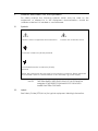
1
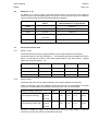
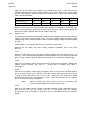
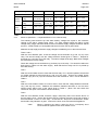
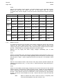
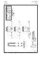
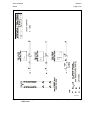
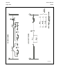
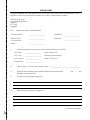
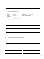
| AUTOMATION MVAX 12, 21, 31, 91 Trip Circuit Supervision Relay Technical Manual R8010Q GRID Note: The technical manual for this device gives instructions for its installation, commissioning, and operation. However, the manual cannot cover all conceivable circumstances or include detailed information on all topics. In the event of questions or specific problems, do not take any action without proper authorization. Contact the appropriate Alstom Grid technical sales office and request the necessary information. Any agreements, commitments, and legal relationships and any obligations on the part of Alstom Grid including settlements of warranties, result solely from the applicable purchase contract, which is not affected by the contents of the technical manual. This device MUST NOT be modified. If any modification is made without the express permission of Alstom Grid, it will invalidate the warranty, and may render the product unsafe. The Alstom Grid logo and any alternative version thereof are trademarks and service marks of Alstom Grid. All trade names or trademarks mentioned herein whether registered or not, are the property of their owners. This manual is provided for informational use only and is subject to change without notice. © 2010, Alstom Grid. All rights reserved. SAFETY SECTION STANDARD SAFETY STATEMENTS AND EXTERNAL LABEL INFORMATION FOR Alstom Grid EQUIPMENT 1. INTRODUCTION This Safety Section and the relevant equipment documentation provide full information on safe handling, commissioning and testing of this equipment. This Safety Section also includes reference to typical equipment label markings. The technical data in this Safety Section is typical only, see the technical data section of the relevant equipment documentation for data specific to a particular equipment. Before carrying out any work on the equipment the user should be familiar with the contents of this Safety Section and the ratings on the equipment’s rating label. Reference should be made to the external connection diagram before the equipment is installed, commissioned or serviced. Language specific, self-adhesive User Interface labels are provided in a bag for some equipment. 2. HEALTH AND SAFETY The information in the Safety Section of the equipment documentation is intended to ensure that equipment is properly installed and handled in order to maintain it in a safe condition. It is assumed that everyone who will be associated with the equipment will be familiar with the contents of this Safety Section, or the Safety Guide (SFTY/4L M). When electrical equipment is in operation, dangerous voltages will be present in certain parts of the equipment. Failure to observe warning notices, incorrect use, or improper use may endanger personnel and equipment and also cause personal injury or physical damage. Before working in the terminal strip area, the equipment must be isolated. Proper and safe operation of the equipment depends on appropriate shipping and handling, proper storage, installation and commissioning, and on careful operation, maintenance and servicing. For this reason only qualified personnel may work on or operate the equipment. Qualified personnel are individuals who: Are familiar with the installation, commissioning, and operation of the equipment and of the system to which it is being connected; Are able to safely perform switching operations in accordance with accepted safety engineering practices and are authorized to energize and de-energize equipment and to isolate, ground, and label it; Are trained in the care and use of safety apparatus in accordance with safety engineering practices; Are trained in emergency procedures (first aid). The equipment documentation gives instructions for its installation, commissioning, and operation. However, the manuals cannot cover all conceivable circumstances or include detailed information on all topics. In the event of questions or specific problems, do not take any action without proper authorization. Contact the appropriate Alstom Grid technical sales office and request the necessary information. 3. SYMBOLS AND LABELS ON THE EQUIPMENT For safety reasons the following symbols which may be used on the equipment or referred to in the equipment documentation, should be understood before it is installed or commissioned. 3.1 Symbols Caution: refer to equipment documentation Caution: risk of electric shock Protective Conductor (*Earth) terminal Functional/Protective Conductor (*Earth) terminal Note: This symbol may also be used for a Protective Conductor (Earth) terminal if that terminal is part of a terminal block or sub-assembly e.g. power supply. *NOTE: 3.2 THE TERM EARTH USED THROUGHOUT THIS TECHNICAL MANUAL IS THE DIRECT EQUIVALENT OF THE NORTH AMERICAN TERM GROUND. Labels See Safety Guide (SFTY/4L M) for typical equipment labeling information. 4. INSTALLING, COMMISSIONING AND SERVICING Equipment connections Personnel undertaking installation, commissioning or servicing work for this equipment should be aware of the correct working procedures to ensure safety. The equipment documentation should be consulted before installing, commissioning, or servicing the equipment. Terminals exposed during installation, commissioning and maintenance may present a hazardous voltage unless the equipment is electrically isolated. Any disassembly of the equipment may expose parts at hazardous voltage, also electronic parts may be damaged if suitable electrostatic voltage discharge (ESD) precautions are not taken. If there is unlocked access to the rear of the equipment, care should be taken by all personnel to avoid electric shock or energy hazards. Voltage and current connections should be made using insulated crimp terminations to ensure that terminal block insulation requirements are maintained for safety. Watchdog (self-monitoring) contacts are provided in numerical relays to indicate the health of the device. Alstom Grid strongly recommends that these contacts are hardwired into the substation's automation system, for alarm purposes. To ensure that wires are correctly terminated the correct crimp terminal and tool for the wire size should be used. The equipment must be connected in accordance with the appropriate connection diagram. Protection Class I Equipment Before energizing the equipment it must be earthed using the protective conductor terminal, if provided, or the appropriate termination of the supply plug in the case of plug connected equipment. The protective conductor (earth) connection must not be removed since the protection against electric shock provided by the equipment would be lost. When the protective (earth) conductor terminal (PCT) is also used to terminate cable screens, etc., it is essential that the integrity of the protective (earth) conductor is checked after the addition or removal of such functional earth connections. For M4 stud PCTs the integrity of the protective (earth) connections should be ensured by use of a locknut or similar. The recommended minimum protective conductor (earth) wire size is 2.5 mm² (3.3 mm² for North America) unless otherwise stated in the technical data section of the equipment documentation, or otherwise required by local or country wiring regulations. The protective conductor (earth) connection must be lowinductance and as short as possible. All connections to the equipment must have a defined potential. Connections that are pre-wired, but not used, should preferably be grounded when binary inputs and output relays are isolated. When binary inputs and output relays are connected to common potential, the pre-wired but unused connections should be connected to the common potential of the grouped connections. Before energizing the equipment, the following should be checked: Voltage rating/polarity (rating label/equipment documentation); CT circuit rating (rating label) and integrity of connections; Protective fuse rating; Integrity of the protective conductor (earth) connection (where applicable); Voltage and current rating of external wiring, applicable to the application. Accidental touching of exposed terminals If working in an area of restricted space, such as a cubicle, where there is a risk of electric shock due to accidental touching of terminals which do not comply with IP20 rating, then a suitable protective barrier should be provided. Equipment use If the equipment is used in a manner not specified by the manufacturer, the protection provided by the equipment may be impaired. Removal of the equipment front panel/cover Removal of the equipment front panel/cover may expose hazardous live parts, which must not be touched until the electrical power is removed. UL and CSA listed or recognized equipment To maintain UL and CSA approvals the equipment should be installed using UL and/or CSA listed or recognized parts of the following type: connection cables, protective fuses/fuseholders or circuit breakers, insulation crimp terminals, and replacement internal battery, as specified in the equipment documentation. Equipment operating conditions The equipment should be operated within the specified electrical and environmental limits. Current transformer circuits Do not open the secondary circuit of a live CT since the high voltage produced may be lethal to personnel and could damage insulation. Generally, for safety, the secondary of the line CT must be shorted before opening any connections to it. For most equipment with ring-terminal connections, the threaded terminal block for current transformer termination has automatic CT shorting on removal of the module. Therefore external shorting of the CTs may not be required, the equipment documentation should be checked to see if this applies. For equipment with pin-terminal connections, the threaded terminal block for current transformer termination does NOT have automatic CT shorting on removal of the module. External resistors, including voltage dependent resistors (VDRs) Where external resistors, including voltage dependent resistors (VDRs), are fitted to the equipment, these may present a risk of electric shock or burns, if touched. Battery replacement Where internal batteries are fitted they should be replaced with the recommended type and be installed with the correct polarity to avoid possible damage to the equipment, buildings and persons. Insulation and dielectric strength testing Insulation testing may leave capacitors charged up to a hazardous voltage. At the end of each part of the test, the voltage should be gradually reduced to zero, to discharge capacitors, before the test leads are disconnected. Insertion of modules and pcb cards Modules and PCB cards must not be inserted into or withdrawn from the equipment whilst it is energized, since this may result in damage. Insertion and withdrawal of extender cards Extender cards are available for some equipment. If an extender card is used, this should not be inserted or withdrawn from the equipment whilst it is energized. This is to avoid possible shock or damage hazards. Hazardous live voltages may be accessible on the extender card. External test blocks and test plugs Great care should be taken when using external test blocks and test plugs such as the MMLG, MMLB and MiCOM P990 types, hazardous voltages may be accessible when using these. *CT shorting links must be in place before the insertion or removal of MMLB test plugs, to avoid potentially lethal voltages. *Note: When a MiCOM P992 Test Plug is inserted into the MiCOM Service Manual MVAX R8010O Page 1/24 TYPE MVAX TRIP CIRCUIT SUPERVISION RELAY Service Manual MVAX R8010O Page 3/24 CONTENTS 1. INSTALLATION 5 1.1 General 5 1.2 Unpacking 5 1.3 Storage 5 1.4 Relay mounting 5 2. COMMISSIONING 6 2.1 General 6 2.2 Wiring 6 2.3 Insulation 6 2.4 MVAX 11 6 2.5 MVAX 12 6 2.6 MVAX 21, 31, 91 7 2.7 Electrical operation tests 7 2.7.1 MVAX 11 only 7 2.7.2 MVAX 12 only 7 2.7.3 MVAX 21 only 8 2.7.4 MVAX 31 (MVAX 91 – 3 separate MVAX 31’s in a size 8 case) 9 2.7.5 MVAX 31 04 only 10 2.7.6 MVAX 31 with CCT breaker closure inhibit contact 11 3. MAINTENANCE 13 4. MECHANICAL SETTINGS 13 4.1 General 13 4.1.1 With the armature closed the clearance between the back of the armature and the back stop should be 0.075/0.2mm (0.003"/0.008"). 13 4.1.2 Nominal armature gap open. 13 4.2 Contact settings 14 4.2.1 MVAX 11 (Unit RL1.) 14 4.2.2 MVAX 12, MVAX 21, 31 (Unit RL1.) 14 4.2.3 MVAX 21 (Unit RL2), MVAX 31 (Units RL2 and RL3) 14 4.3 Mechanical flag settings 14 R8010O Page 4/24 MVAX 4.3.1 Hand reset reverse flags 14 4.3.2 Self reset reverse flags 14 5. PROBLEM ANALYSIS 15 5.1 Failure to operate/reset 15 5.2 Output contacts not changing state. 15 5.3 Reset time on MVAX 12 too short. 15 6. SPARES 15 6.1 Repairs 15 7. COMMISSIONING TEST RECORD 23 FIGURES Figure 1: Circuit and application diagram – trip supervision relay 16 Figure 2: Supervision of interposing control relay type MVAW 17 Figure 3: Supervision of tripping relay type MVAJ 17 Figure 4: Circuit diagram – MVAX21 trip circuit supervision relay without preclosing supervision 18 Application diagram – MVAX21 trip circuit supervision relay without preclosing supervision 19 Circuit diagram – MVAX31 trip circuit supervision relay with preclosing supervision 20 Application diagram - MVAX31 trip circuit supervision relay with preclosing supervision 21 Figure 5: Figure 6: Figure 7: Service Manual MVAX R8010O Page 5/24 1. INSTALLATION 1.1 General Protective relays, although generally of robust construction, require careful treatment prior to installation on site. By observing a few simple rules the possiblity of premature failure is eliminated and a high degree of performance can be expected. Relays are either despatched individually or as part of a panel/rack mounted assembly in cartons specifically designed to protect them from damage. Relays should be examined immediately they are received to ensure that no damage has been sustained in transit. If damage has been sustained in transit, a claim should be made to the transport company concerned immediately, and the nearest Alstom Grid representative should be promptly notified. 1.2 Unpacking Care must be taken when unpacking and installing the relays so that none of the parts are damaged or their settings altered, and must at all times be handled by skilled persons only. Relays should be examined for any wedges, clamps, or rubber bands necessary to secure moving parts to prevent damage during transit and these should be removed after installation and before commissioning. Relays which have been removed from their cases should not be left in situations where they are exposed to dust or damp. This particularly applies to installations which are being carried out at the same time as constructional work. 1.3 Storage If relays are not installed immediately upon receipt they should be stored in a place free from dust and moisture in their original cartons and where de-humidifier bags have been included in the packing they should be retained. The action of the de-humidifier crystals will be impaired if the bag has been exposed to ambient conditions and may be restored by gently heating the bag for about an hour, prior to replacing it in the carton. Dust which collects on a carton may, on subsequent unpacking, find its way into the relay; in damp conditions the carton and packing may become impregnated with moisture and the dehumidifying agent will lose its efficiency. The storage temperature range is –25°C to +70°C. 1.4 Relay mounting The installation should be clean, dry and reasonably free from dust and excessive vibration. The site should preferably be well illuminated to facilitate inspection. An outline diagram is normally supplied showing panel cut-outs and hole centers. For individually mounted relays these dimensions will also be found in Publications R6103 MVAX 11 and R6010 MVAX 12, 21, 31 and 91. Publication R7012 is a Parts Catalogue and Assembly Instructions. This document will be useful when individual relays are to be assembled as a composite rack or panel mounted assembly. Publication R6001 is a leaflet on the modular integrated drawout system of protective relays. Publication R6014 is a list of recommended suppliers for the pre-insulated connectors. R8010O Service Manual Page 6/24 MVAX 2. COMMISSIONING 2.1 General Before leaving the factory all relays are accurately adjusted, tested and carefully packed. Hence there should be no need for any re-adjustment on commissioning. Moving parts are held in position during transit by rubber bands and packing. These should be removed carefully. To gain access to the relay first loosen the captive cover screws. Then carefully remove the cover from the case. The module can then be removed from the case by grasping the handles at the top and bottom of the front plate and pulling forwards. Care must be taken to ensure that mechanical settings of the element are not disturbed. Carefully remove the rubber band securing the flag mechanism. Check that the ends of the push rods are located in the holes in the contact springs. Carefully actuate the armature of each unit in turn with a small screwdriver/probe. Note immediately after the point where any make contacts just close there is a further small movement of the armature. This ensures that contact follow through and wiping action is present. Repeat similarly with break contacts on armature release. On units fitted with hand reset flag indicators, check that the flag is free to fall before, or just as, any make contacts close. Replace the module in the case and refit the cover. Make sure that the reset mechanism in the cover is correctly located with respect to the relay element, and that the flag (or mechanism) can be reset. 2.2 Wiring Check that ratings of the relay agree with the supplies to which it is to be connected. Check all wiring connections to the relay, including the case earthing connection above the terminal block. It is especially important that dc supplies are wired with the correct polarity. The relay diagram number appears inside the case. 2.3 Insulation The relay, and its associated wiring, may be insulation tested between: a) all electrically isolated circuits b) all circuits and earth An electronic or brushless insulation tester should be used, having a dc voltage not exceeding 1000V. Accessible terminals of the same circuit should first be strapped together. Deliberate circuit earthing links, removed for the tests, subsequently must be replaced. 2.4 MVAX 11 With MVAX 11 relays check that all wiring complies to the appropriate application diagram to ensure that the relay is wired correctly. 2.5 MVAX 12 With MVAX 12 relays, check that terminal 13 of the relay case is wired to the POSITIVE of the trip supply. Service Manual R8010O MVAX 2.6 Page 7/24 MVAX 21, 31, 91 For MVAX 21, 31 and 91 relays, check the external wiring to ensure the correct values of external resistors (where appropriate) are wired to the correct relay terminals, in accordance with the following table and the appropriate application diagram. Supply volts Alarm supply circuit REXT1 Trip supply circuit REXT2 and REXT3, as appropriate 24/27 - 270 ohm 30/34 – 470 ohm 48/54 240 ohm 1,500 ohm 110/125 1,500 ohm 4,000 ohm *1,200 ohm 220/250 4,100 ohm 2 off 4,000 ohm in series * S/R reverse flag 2.7 Electrical operation tests 2.7.1 MVAX 11 only Isolate the MVAX from the trip supply batteries by removing fuses/links as necessary. Connect a supply across relay terminals 21 – 27 and supply the relevant voltage from the list below. Check that the current is within those figures stated in the same column. Repeat again only using terminals 27 – 28. 2.7.2 Rated voltage range (V) 30/34 48/54 110/125 120/250 Test voltage (V) 30 48 110 220 Terminals 21 – 27 46.1/56.3mA 24.1/29.5mA 11/13.4mA 11.4/14mA Terminals 27 – 28 46.1/56.3mA 24.1/29.5mA 11/13.4mA 11.4/14mA MVAX 12 only Isolate the relay from the trip supply batteries by removing fuses/links as necessary. Using an ohmmeter check the resistance across the relay side of the fuses/links. Provided there are no parallel paths, the resistance should be within ±10% of the following: MVAX 12 rating range (V) 24/27 30/34 48/54 110/125 220/250 Relay resistance (Ohms): No flag/hand reset flag 2 contacts 4 contacts 710 416 1170 620 2970 1760 10370 7470 33100 23100 Relay resistance (Ohms): No flag/hand reverse flag 2 contacts 4 contacts 590 407 940 590 2330 1740 8670 6770 27100 22100 Connect a variable dc supply to the isolated circuit ensuring correct polarity is observed (Terminal 13 of the relay must be maintained POSITIVE). R8010O Service Manual Page 8/24 MVAX Apply 75% of the relay’s lower voltage of the voltage rating range. Check that the relay operates satisfactorily and that the flag indication can be reset. Reduce the voltage slowly until the relay drops-off. Check that this occurs between 25% to 40% of the lower voltage rating, as indicated below: V rating range 24/27 30/34 48/54 110/125 220/250 75% of lower (V) 18 22.5 36 82.5 165 25-40% of lower (V) 6 – 9.6 7.5 – 12 12 – 19.2 27.5 – 44 55 – 88 Replace all links and fuses. Check that the relay operates and manually reset the flag. With alarm circuits operational, temporarily remove a trip supply fuse. Check that the appropriate alarms are initiated. Replace the fuse and reset the relay flag. 2.7.3 MVAX 21 only The following tests assume trip and alarm supply battery voltages are equal to the maximum voltage of the relay’s voltage rating range. For other voltages within the relays normal voltage rating range, tolerance bands for other measured supply voltages should be altered pro-rata. A table (Table 1) of acceptable tolerances for each test is given below. Measure the trip supply and alarm supply voltages immediately prior to the tests and note. Test 1 With the circuit breaker open, check that no voltage appears across terminals 13 and 14 of the relay. Check that the voltage appearing across terminals 21(+) and 28 comply with that given in Table 1 (alarm supply) and that the front relay, RL1, has operated. Reset its flag. Test 2 With the circuit breaker closed, check that the front relay remains operated. Measure the voltage across terminals 13(+) and 14. Ensure that it complies with Table 1 (Trip supply). Test 3 With the circuit breaker closed, apply a temporary short circuit across the external resistor REXT2* of the trip supply circuit. Ensure the CB does not trip. Remove the short circuit and re-apply it across terminals 13 and 14 of the relay. Check that RL1 drops-off to initiate alarm circuits and that RL1 flag indication is given. Ensure the CB does not trip. Remove the short circuit and reset the flag/alarms. *Note: Where 2 resistors are used in series for REXT2, a temporary short circuit should be applied across each resistor in turn. Test 4 With the circuit breaker closed, operate, or simulate operation of the associated trip relay. Note that the CB trips but ensure that RL1 of the MVAX does not operate. RL1 and RL2 units are slugged on drop-off to prevent mal-operation during the transition period. Service Manual R8010O MVAX Page 9/24 Relay V. rating 24/27 30/34 48/54 110/125 220/250 Ref. V. for tolerance 27 34 48 110 220 Test 1 (Alarm supply) Hand reset flag Full volts (no ext. R) Full volts (no ext. R) 35.3 – 38.8 29.1 – 36.3 24.9 – 32.5 Self reset flag Full volts (no ext. R) Full volts (no ext. R) 37.1 – 40.4 38.2 – 46.6 28.5 – 37.0 Hand reset flag 15.0 – 17.0 18.0 – 20.5 25.8 – 29.8 53.6 – 61.2 107.0 – 120.9 Self reset flag 12.0 – 14.0 18.0 – 20.5 25.8 – 29.8 53.6 – 61.2 107.0 – 120.9 Test 2 (Trip supply) Table 1 2.7.4 MVAX 31 (MVAX 91 – 3 separate MVAX 31’s in a size 8 case) The following tests assume trip and alarm battery voltages are equal to the maximum voltage of the relay’s voltage rating range. For other voltages within the relay’s normal voltage rating range, tolerance bands for other measured supply voltages should be altered pro-rata. A table (Table 2) of acceptable tolerances for each test is given below. Measure the trip supply and alarm supply voltages immediately prior to the tests and note. Tests 1 and 2 With the circuit breaker open, check the voltage across terminals 13(+) and 14(–ve) of the relay. This should comply with the voltage tolerance limited given in Table 2. Repeat for terminals 21(+) and 22(–ve) of the relay. The same voltage limits apply. Both these voltages are derived from the trip supply. Check the voltage across terminals 27(+) and 28(–ve) of the relay. This should be within the limits given in Table 2 for the alarm supply. Note that the front relay unit RL1 is picked-up and reset its flag. Test 3 With the circuit breaker closed check that the front relay RL1, remains operated. Check that no voltage appears across terminals 21 and 22 of the relay. Ensure the voltage across terminals 13(+) and 14(–ve) has increased from that obtained in Test 1 to that indicated in Table 2. Test 4 With the circuit breaker closed, as in test 3 above, check that the voltage between terminals 14(+) and 22(–ve) is zero. Measure the resistance between terminals 14 and 22 which should comply within ±10% of the values given in Table 2. (Note: This test check that contact 52–b is open in the breaker closed condition). Test 5 With the circuit breaker closed, as above, apply a temporary short circuit across REXT2* of the trip supply circuit. Ensure the CB does not trip. Remove the short circuit and re-apply it across terminals 13 and 14 of the relay. Check that RL1 drops off to initiate alarm circuits and that RL1 flag indication is given. Remove the short circuit and reset the flag/alarms. *Note: Where 2 resistors are used in series for REXT2, a temporary short circuit should be applied across each resistor in turn. R8010O Service Manual Page 10/24 MVAX Test 6 With the circuit breaker closed, operate, or simulate operation of the associated trip relay. Ensure the CB trips but ensure that RL1 of the MVAX does not operate. The MVAX relay units are slugged on drop-off to prevent mal-operation during the transition period. Relay V. rating 24/27 30/34 48/54 110/125 220/250 Ref. V. for tolerance 27 34 54 125 250 Hand reset flag 7.8 – 8.2V 9.4 – 9.8V 13.6 – 14.2V 27.9 – 29.4V 55.3 – 58.4V Self reset flag 6.3 – 6.7V 9.4 – 9.8V 13.6 – 14.2V 27.9 – 29.4V 55.3 – 58.4V Hand reset flag Full volts (no ext. R) Full volts (no ext. R) 36.5 – 42.7V 31.3 – 38.8V 27.3 – 33.8V Self reset flag Full volts (no ext. R) Full volts (no ext. R) 38.2 – 39.3V 40.9 – 43.7V 31.1 – 34.0V Hand reset flag 15.7 – 16.3V 18.8–19.7V 27.1 – 28.5V 55.8 – 58.9V 110.6 –116.8V Self reset flag 12.7 – 13.3V 18.8–19.7V 27.1 – 28.5V 55.8 – 58.9V 110.6 –116.8V Hand reset flag 665 1085 3100 7400 14700 Self reset flag 522 1085 3100 7400 14700 Test 1 (Trip supply) Test 2 (Alarm supply) Test 3 (Trip supply) Test 4 Table 2 2.7.5 MVAX 31 04 only The following test assume trip and alarm supply battery voltages are equal to the maximum voltage for the relays voltage rating range. For other voltages within the relays normal voltage rating range, tolerance bands for other measured supply voltages should be altered pro-rata. A Table (Table 1) of acceptable tolerance for the test is given. Measure the trip supply and alarm supply voltages immediately prior to tests and note. Test 1 With the circuit breakers open, check that no voltage appears across terminals 13 and 14, 21 and 22 of the relay. Check that the voltage appearing across terminals 27(+) and 28 comply with that given in Figure 1 (alarm supply) and that the front relay RL1, has operated. Reset the flag. Test 2 With the circuit breakers closed, check that the front relay remains operated. Measure the voltage across terminals 13(+), 14, 21(+) and 22. Ensure that these comply with Figure 1 (trip supply). Test 3 With the circuit breakers closed, apply a temporary short circuit across each of the external resistors REXT2(1)* and REXT2(2)* of the trip supply circuits. Ensure the circuit breakers do not trip. Remove the short circuits and reapply them across terminals 13 and 14 and 22 of the relay. Check that RL1 drops-off to initiate alarm circuits and that the RL1 flag indication is given. Ensure the circuit breakers do not trip. Remove the short circuits and reset the flag/alarms. *Note: Where 2 resistors are used in series for REXT2, a temporary short circuit should be applied across each resistor in turn. Service Manual R8010O MVAX Page 11/24 Test 4 With the circuit breakers closed, operate or simulate operation of the associated trip relays. Note that the circuit breakers trip but ensure that RL1 of the MVAX does not operate. RL1, RL2(1) and RL2(2) units are slugged on drop-off to prevent mal-operation during the transition period. Restore any external wiring connections that may have been disturbed during the above tests. 2.7.6 MVAX 31 with CCT breaker closure inhibit contact The following tests assume trip and alarm battery voltages are equal to the maximum voltage of the relay’s voltage rating range. For other voltages within the relay’s normal voltage rating range, tolerance bands for other measured supply voltages should be altered pro-rata. A table (Table 3) of acceptable tolerances for each test is given below. Measure the trip supply and alarm supply voltages immediately prior to the tests and note. Tests 1 and 2 With the circuit breaker open, check the voltage across terminals 13(+) and 14(–ve) of the relay. This should comply with the voltage tolerance limited given in Table 3. Repeat for terminals 21(+) and 22(–ve) of the relay. The same voltage limits apply. Both these voltages are derived from the trip supply. Check the voltage across terminals 27(+) and 28(–ve) of the relay. This should be within the limits given in Table 3 for the alarm supply. Note that the front relay unit RL1 is picked-up and reset its flag. Test 3 With the circuit breaker closed check that the front relay RL1, remains operated. Check that no voltage appears across terminals 21 and 22 of the relay. Ensure the voltage across terminals 13(+) and 14(–ve) has increased from that obtained in Test 1 to that indicated in Table 3. Test 4 With the circuit breaker closed, as in test 3 above, check that the voltage between terminals 14(+) and 22(–ve) is zero. Measure the resistance between terminals 14 and 22 which should comply within ±10% of the values given in Table 3. (Note: This test check that contact 52–b is open in the breaker closed condition). Test 5 With the circuit breaker closed, as above, apply a temporary short circuit across REXT2* of the trip supply circuit. Ensure the CB does not trip. Remove the short circuit and re-apply it across terminals 13 and 14 of the relay. Check that RL1 drops off to initiate alarm circuits and that RL1 flag indication is given. Remove the short circuit and reset the flag/alarms. *Note: Where 2 resistors are used in series for REXT2, a temporary short circuit should be applied across each resistor in turn. R8010O Service Manual Page 12/24 MVAX Test 6 With the circuit breaker closed, operate, or simulate operation of the associated trip relay. Ensure the CB trips but ensure that RL1 of the MVAX does not operate. The MVAX relay units are slugged on drop-off to prevent mal-operation during the transition period. Relay V. rating 110/125 Ref. V. for tolerance 125 Test 1 (Trip supply) Test 2 (Alarm supply) Test 3 (Trip supply) Test 4 Hand reset flag 25.8 – 31.6V Self reset flag 25.8 – 31.6V Hand reset flag 31.3 – 38.8V Self reset flag 38 – 46.6V Hand reset flag 51.6 – 63.1V Self reset flag 51.6 – 63.1V Hand reset flag 7400 Self reset flag 7400 Table 3 MVAX31 with CCT breaker clsoure inhibit contact Service Manual R8010P MVAX 3. Page 13/24 MAINTENANCE Periodic maintenance is not necessary. However, periodic inspection and test is recommended. This should be carried out every 12 months or more often if the relay is operated frequently or is mounted in poor environmental conditions. Tests 2.3, 2.4, 2.5, 2,6 and 2.7 should be carried out to prove operation. 4. MECHANICAL SETTINGS 4.1 General Armature gap measurements should be made with the top of the feeler gauge level with the centre line of the core. Contact pressures are measured with a gramme gauge at the contact tips. In general contact gaps and follow through are defined by quoting an armature gap at which the tips should be just closed or just open. The relay contact state is always defined with the relay in the unenergised position, unless otherwise specified on the appropriate circuit diagram. Symbol used on diagrams Contact Type Normal duty Make (Normally open) M Break (Normally closed) B 4.1.1 With the armature closed the clearance between the back of the armature and the back stop should be 0.075/0.2mm (0.003"/0.008"). 4.1.2 Nominal armature gap open. MVAX 11 Unit RL1 1.38mm (0.055") MVAX 12 MVAX 21, 31 and 91 Unit RL1 MVAX 21 Unit RL2 MVAX 31, 91 Unit RL2 and RL3 Note: 1.5mm (0.060") 0.7mm (0.030") On the MVAX 12 a screw is fitted to the armature. It must protrude by 0.075/0.2mm (0.003"/0.008"). R8010O Service Manual Page 14/24 MVAX 4.2 Contact settings 4.2.1 MVAX 11 (Unit RL1.) With the armature closed onto a 0.25mm (0.011") feeler gauge the make contacts should be closed, but should be open using a 0.38mm (0.015") feeler gauge. 4.2.2 Force to just close the break contacts: 20/25 grams. Force to just open the break contacts: 18/23 grams. Contact gap: 1.5/1.75mm (0.06/0.07"). MVAX 12, MVAX 21, 31 (Unit RL1.) With the armature closed onto a 0.25mm (0.011") feeler gauge the make contacts should be closed, but should be open using a 0.35mm (0.013") feeler gauge. With the armature closed onto a 0.75mm (0.029") feeler gauge the break contact should be open, but should be closed using a 0.8mm (0.031") feeler gauge. Force to just close the make contacts: 20/25 grams. Force to just open the break contacts: 20/25 grams. Force to just lift the fixed contact off its support: 15/20 grams. Contact gap for make and break contacts: 1.75/2mm (0.07/0.08"). Note: 4.2.3 On MVAX 21, 31 Relays - To measure the force to just close or the force to just break on the lower right hand contact when viewed from the front of the module, it is necessary to carefully lift the upper moving contact blade to remove the pressure on the lower contact. MVAX 21 (Unit RL2), MVAX 31 (Units RL2 and RL3) With the armature closed onto a 0.25mm (0.011") feeler gauge the make contact should be closed, but should be open using a 0.35mm (0.013") feeler gauge. Force to just close the make contact: 10/15 grams. Force to just lift the fixed contact off its support: 10/15 grams. Contact gap: 1.0/1.1mm (0.038/0.042"). 4.3 Mechanical flag settings 4.3.1 Hand reset reverse flags With the armature closed onto a 0.45mm (0.018") feeler gauge, the flag should be free to fall, but should not fall using a 0.35mm (0.013") feeler gauge. Adjustment is made to the catch spring on the flag. 4.3.2 Self reset reverse flags Adjust the flag operating lever such that the flag side arm is parallel to the frame, when viewed from the side and the flag covers the flag label. Service Manual R8010O MVAX Page 15/24 5. PROBLEM ANALYSIS 5.1 Failure to operate/reset Check diagram for correct input connections. Check the correct voltages are applied. Ratings values are shown on module front plate. Ensure the power supply is capable of supplying the necessary power. Ensure correct series resistors are used and connected to correct relay terminals. Flag spring may have been distorted and is holding the armature open or closed. Check internal wiring. Check continuity – result open circuit. Coil open circuit. Internal wiring damaged. Series resistor open circuit (resistors may be internal or external). 5.2 Output contacts not changing state. Pushrod not in position. Check output terminals with reference to diagram. Contamination of contacts. MVAX 21, 31, 91. Units RL2, RL3 contacts not closing. 5.3 Reset time on MVAX 12 too short. Check capacitor C1 is not open circuit or short circuit. Contacts should be cleaned with the burnishing tool supplied in relay tool kits. On no account should knives, files or abrasive materials be used. Check mechanical settings as per Section 4. 6. SPARES When ordering spares, quote the full relay model number and any component references numbers, or briefly describe the parts required. 6.1 Repairs Should the need arise for the equipment to be returned to Alstom Grid for repair, then the form at the back of this manual should be completed and sent with the equipment together with a copy of any commissioning test results. Figure 1: 4 6 14 22 28 3 5 13 21 27 Circuit and application diagram – trip supply supervision relay Short terminals break before (c). Long terminals. (c) CT shorting links make before (b) and (c) disconnect. (b) (a) Note 1 Module terminal block viewed from rear 2 1 Case earth 13 C1 R1 2 4 2M 1M RL1 2 R2 1 3 1B 2B Combinations of output contacts 2 4 M B B 14 M : Make B : Break Contact descriptions 1 3 M M B Output contacts to module terminals R8010O Service Manual Page 16/24 MVAX Service Manual R8010O MVAX Page 17/24 Push button MVAW Interposing control relay R1 21 R2 27 1 Figure 2: MVAX 11 Supervisory relay 3 2 28 4 P1077ENa Supervision of interposing control relay type MVAW MVAJ Tripping relay Protective relay contact R1 Supervision relay 27 1 Figure 3: R2 28 MVAX 11 3 21 2 Supervision of tripping relay type MVAJ 4 P1078ENa Figure 4: 6 8 10 12 14 22 28 3 5 7 9 1 13 21 27 Short terminals break before (c). Long terminals. (c) CT shorting links make before (b) and (c) disconnect. (b) (a) Note 1 Module terminal block viewed from rear 2 4 1 Case earth Vx Vx 21 27 13 RL2-1 R1 RL2 2 4 RL1 3 1 3 5 7 Viewed from front M Viewed from front 3B 28 14 1B 2B 3M 2M 1M Combinations of output contacts B 5 7 M M M B 2 4 M M B M : Make B : Break Contact descriptions B 1 3 M B B Output contacts to module terminals R8010O Service Manual Page 18/24 MVAX P1079ENa Circuit diagram – MVAX21 trip circuit supervision relay without preclosing supervision Figure 5: 13 C.B. aux. switch 52-b REXT(2) Trip relay RL2 27 21 RL2-1 Alarm supply (Vx (1)) 14 C.B. aux. switch 52-a Trip supply (Vx (2)) RL1 3 Trip coil 52 T Trip coil 28 REXT(1) RL1-3 RL1-2 RL1-1 7 4 3 Note: Contact arrangement shown is typical only. 5 2 1 Alarm contacts Service Manual R8010O MVAX Page 19/24 P1080ENa Application diagram – MVAX21 trip circuit supervision relay without supervision preclosing R8010O Page 20/24 Service Manual MVAX P4066ENa Figure 6: Circuit diagram – MVAX31 trip circuit supervision relay with preclosing supervision Service Manual MVAX R8010O Page 21/24 P4067ENa Figure 7: Application diagram - MVAX31 trip circuit supervision relay with preclosing supervision R8010O Page 22/24 Service Manual MVAX P4068ENa Service Manual R8010O MVAX 7. Page 23/24 COMMISSIONING TEST RECORD Trip Supply Supervision Relay Type MVAX 11 – Type MVAX 12 – Type MVAX 21 – Type MVAX 31 – Type MVAX 91 (delete as appropriate) Date Station Circuit Reay Model No Serial No Relay type Circuit/supply ref. V. rating range Value of ext. resistor fitted MVAX 11 Trip/Vx1 /V MVAX 12 Trip/Vx1 /V REXT1 ohms MVAX 21 Alarm/Vx1 /V REXT1 ohms Trip/Vx2 /V REXT2 ohms Alarm/Vx1 /V REXT1 ohms Trip/Vx2 /V REXT2/3 ohms MVAX 31/91 N/A Commissioning preliminaries Tick if satisfactory Insulation tests: Satisfactory Test results: Not required MVAX 11 relay Test 2.7.1 Resistance across terminals 21 – 27 / Ω 27 – 28 / Ω Trip supply voltage V CB open Relay stable CB closed Relay stable Trip circuit open Relay operates Contacts checked Test results: *Test 2.7.2 MVAX 12 relay * Relay resistance ohms * Relay operates satisfactlorily at Volts * Relay drops off at Volts Fuse removal. Alarm initiation satisfactory * Note: These tests omitted only at site engineers discretion tick R8010O Service Manual Page 24/24 MVAX Test results: MVAX 21 relay Test 2.7.3 Measured trip supply 1 2 CB open CB closed 3 Test results: (tick) V alarm supply V Volts across terminals 13 and 14 V Volts across terminals 21 and 28 V Volts across terminals 13 and 14 V 4 (tick) MVAX 31 relay Test 2.7.4 Measured trip supply (1 and 2) CB open 3 CB closed 4 CB closed 5 alarm supply Volts across terminals 13 and 14 21 & 2 V 6 V V 21 and 22 V 27 and 28 V 13 and 14 V Resistance between 14 and 22 (tick) Note: V (tick) For details of the above tests, see Publication R8010. Comments: Commissioning Engineer Customer Witness Date Date ohms REPAIR FORM Please complete this form and return it to Alstom Grid – SAS with the equipment to be repaired. This form may also be used in the case of application queries. Alstom Grid – SAS St. Leonards Avenue Stafford ST17 4LX England For : After Sales Service Department Customer Ref: ___________________ Model No: ___________________ Alstom Grid Contract Ref: ___________________ Serial No: ___________________ Date: ___________________ 1. What parameters were in use at the time the fault occurred AC Volts ___________________ Main VT/Test set DC Volts ___________________ Battery/Power supply AC current ___________________ Main CT/Test set Frequency ___________________ 2. Which type of test was being used _____________________________________ 3. Were all the external components fitted where required? (Delete as appropriate) 4. List the relay settings being used 5. What did you expect to happen Yes / No continued overleaf What did happen 7. When did the fault occur Instant Yes / No Intermittent Time delayed Yes / No (Delete as appropriate) By how long __________________ _ 8. What indications if any did the relay show 9. Was there any visual damage 10. Any other remarks which may be useful: Yes / No Signature Title Name (in capitals) Company name 6. PUBLICATION: R8010Q Alstom Grid Substation Automation Solutions Business www.alstom.com/grid Alstom Grid Worldwide Contact Centre online 24 hours a day: +44 (0) 1785 250 070 www.alstom.com/grid/contactcentre/