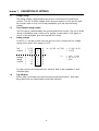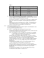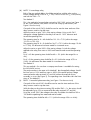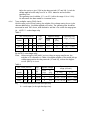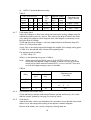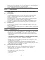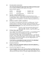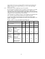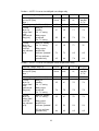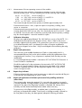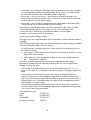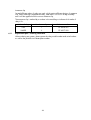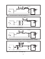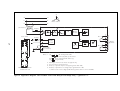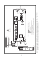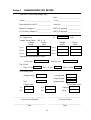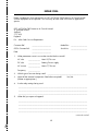
1
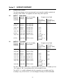
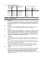
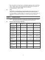
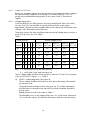
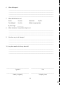
Service Manual
Type MVTD
Inverse Time Delayed Relays
HANDLING OF ELECTRONIC EQUIPMENT
A person's normal movements can easily generate electrostatic potentials of several thousand volts.
Discharge of these voltages into semiconductor devices when handling electronic circuits can cause
serious damage, which often may not be immediately apparent but the reliability of the circuit will have
been reduced.
The electronic circuits of GEC ALSTHOM T&D Protection & Control Limited products are completely safe
from electrostatic discharge when housed in the case. Do not expose them to the risk of damage by
withdrawing modules unnecessarily.
Each module incorporates the highest practicable protection for its semiconductor devices. However, if it
becomes necessary to withdraw a module, the following precautions should be taken to preserve the high
reliability and long life for which the equipment has been designed and manufactured.
1. Before removing a module, ensure that you are at the same electrostatic potential as the equipment
by touching the case.
2. Handle the module by its front-plate, frame, or edges of the printed circuit board.
Avoid touching the electronic components, printed circuit track or connectors.
3. Do not pass the module to any person without first ensuring that you are both at the same
electrostatic potential. Shaking hands achieves equipotential.
4. Place the module on an antistatic surface, or on a conducting surface which is at the same
potential as yourself.
5. Store or transport the module in a conductive bag.
More information on safe working procedures for all electronic equipment can be found in BS5783 and
IEC 147-0F.
If you are making measurements on the internal electronic circuitry of an equipment in service, it is
preferable that you are earthed to the case with a conductive wrist strap.
Wrist straps should have a resistance to ground between 500k – 10M ohms. If a wrist strap is not
available, you should maintain regular contact with the case to prevent the build up of static.
Instrumentation which may be used for making measurements should be earthed to the case whenever
possible.
GEC ALSTHOM T&D Protection & Control Limited strongly recommends that detailed investigations on the
electronic circuitry, or modification work, should be carried out in a Special Handling Area such as
described in BS5783 or IEC 147-0F.
Types:
MVTD11 Inverse Time Delayed Undervoltage Relay
MVTD12 Inverse Time Delayed Overvoltage Relay
MVTD13 Inverse Time Delayed Neutral Displacement Relay
CONTENTS
SAFETY SECTION
5
1
1.1
1.2
1.3
1.4
DESCRIPTION OF SETTINGS
Voltage settings
Time multiplier setting switches
Setting example
Trip indication
8
8
8
8
8
2
2.1
2.2
2.3
2.4
AUXILIARY EQUIPMENT
External series resistors
MVTD 11 – Undervoltage
MVTD 12 – Overvoltage
MVTD 13 Neutral Displacement
9
9
9
9
10
3
3.1
3.2
3.3
3.4
3.5
3.6
INSTALLATION
Precautions
Packing
Inspection
Unpacking
Storage
Siting
10
10
10
10
10
10
11
4
4.1
4.2
4.3
COMMISSIONING
Relevant sections for testing of each relay
Commissioning preliminaries
Commissioning tests
11
11
12
13
5
5.1
5.2
MAINTENANCE
Visual inspection
Functional checks
20
20
20
6
6.1
6.2
6.3
6.4
6.5
6.6
6.7
6.8
6.9
6.10
20
20
21
21
21
21
21
24
24
24
6.11
PROBLEM ANALYSIS
Test equipment required for fault finding
General procedure and precautions
Inspection – removal of module from case
Connections for MVTD 11, MVTD 12 and MVTD 13
Checking voltage supplies to module
Printed circuit board tests
Calibration information
Repairs and replacements
Repair of trip indicator
Repair and replacement of miniature pcb mounted relay and flag mechanism
(where fitted)
Replacement parts – ordering information
7
COMMISSIONING TEST RECORD
33
REPAIR FORM
35
4
24
26
SAFETY SECTION
This Safety Section should be read before commencing any work on the equipment.
Health and safety
The information in the Safety Section of the product documentation is intended to
ensure that products are properly installed and handled in order to maintain them in
a safe condition. It is assumed that everyone who will be associated with the
equipment will be familiar with the contents of the Safety Section.
Explanation of symbols and labels
The meaning of symbols and labels which may be used on the equipment or in the
product documentation, is given below.
Caution: refer to product documentation
Caution: risk of electric shock
Protective/safety *earth terminal
Functional *earth terminal.
Note: this symbol may also be used for a protective/
safety earth terminal if that terminal is part of a
terminal block or sub-assembly eg. power supply.
*Note: The term earth used throughout the product documentation is the direct
equivalent of the North American term ground.
Installing, Commissioning and Servicing
Equipment connections
Personnel undertaking installation, commissioning or servicing work on this
equipment should be aware of the correct working procedures to ensure safety.
The product documentation should be consulted before installing, commissioning or
servicing the equipment.
Terminals exposed during installation, commissioning and maintenance may present
a hazardous voltage unless the equipment is electrically isolated.
If there is unlocked access to the rear of the equipment, care should be taken by all
personnel to avoid electric shock or energy hazards.
Before energising the equipment it must be earthed using the protective earth
terminal, or the appropriate termination of the supply plug in the case of plug
connected equipment. Omitting or disconnecting the equipment earth may cause a
safety hazard.
5
The recommended minimum earth wire size is 2.5 mm2, unless otherwise stated in
the Technical Data section of the product documentation.
Before energising the equipment, the following should be checked:
Voltage rating and polarity;
CT circuit rating and integrity of connections;
Protective fuse rating;
Integrity of earth connection (where applicable)
Equipment operating conditions
The equipment should be operated within the specified electrical and environmental
limits.
Battery replacement
Where internal batteries are fitted they should be replaced with the recommended
type and be installed with the correct polarity, to avoid possible damage to the
equipment.
Insertion of modules and pcb cards
These must not be inserted into or withdrawn from equipment whilst it is energised,
since this may result in damage.
Current transformer circuits
Do not open the secondary circuit of a live CT since the high voltage produced
may be lethal to personnel and could damage insulation.
External resistors
Where external resistors are fitted to relays, these may present a risk of electric shock
or burns, if touched.
Insulation and dielectric strength testing
Insulation testing may leave capacitors charged up to a hazardous voltage. At the
end of each part of the test, the voltage should be gradually reduced to zero, to
discharge capacitors, before the test leads are disconnected.
Insertion and withdrawal of heavy current test plugs
When using a heavy current test plug, CT shorting links must be in place before
insertion or removal, to avoid potentially lethal voltages.
Fibre optic communication
Where fibre optic communication devices are fitted, these should not be viewed
directly. Optical power meters should be used to determine the operation or signal
level of the device.
6
Decommissioning and Disposal
Decommissioning: The auxiliary supply circuit in the relay may include capacitors
across the supply or to earth. To avoid electric shock or energy
hazards, after completely isolating the supplies to the relay
(both poles of any dc supply), the capacitors should be safely
discharged via the external terminals prior to decommissioning.
Disposal:
It is recommended that incineration and disposal to water
courses is avoided. The product should be disposed of in a safe
manner. Any products containing batteries should have them
removed before disposal, taking precautions to avoid short
circuits. Particular regulations within the country of operation,
may apply to the disposal of lithium batteries.
Technical Specifications
Protective fuse rating
The recommended maximum rating of the external protective fuse for this equipment
is 16A, GEC Red Spot type or equivalent, unless otherwise stated in the Technical
Data section of the product documentation.
Insulation class: IEC 1010-1: 1990/A2: 1995
Class I
EN 61010-1: 1993/A2: 1995
Class I
This equipment requires a
protective (safety) earth
connection to ensure user
safety.
Installation
Category
(Overvoltage):
IEC 1010-1: 1990/A2: 1995
Category III
EN 61010-1: 1993/A2: 1995
Category III
Distribution level, fixed
installation. Equipment in
this category is qualification
tested at 5kV peak, 1.2/50µs,
500Ω, 0.5J, between all supply
circuits and earth and also
between independent circuits.
Environment:
IEC 1010-1: 1990/A2: 1995
Pollution degree 2
EN 61010-1: 1993/A2: 1995
Pollution degree 2
Compliance is demonstrated by
reference to generic safety
standards.
Product safety:
73/23/EEC
Compliance with the European
Commission Low Voltage
Directive.
EN 61010-1: 1993/A2: 1995
EN 60950: 1992/A3: 1995
Compliance is demonstrated
by reference to generic safety
standards.
7
Section 1
1.1
DESCRIPTION OF SETTINGS
Voltage settings
The setting voltage is determined by the positions of the bottom five dual-in-line
switches. The sum of all the voltages shown by each respective switch position and
the constant value as show on the relay nameplate, gives the required setting
voltage.
1.2
Time multiplier setting switches
The TMS setting is determined by the top three dual-in-line switches. The sum of all the
settings indicated by each switch position and the constant value 0.125, again as
shown on the nameplate, gives the required TMS setting.
1.3
Setting example
An MVTD 11 with the switches set to the position shown corresponds to a voltage
setting of 80V and a TMS setting of 0.375.
TMS
switches
Voltage
setting
switches
( 0.125
( 0.25
(
0.5
-->
<--->
0
0
0
(
(
(
(
(
-->
-->
<-<--->
0
0
0
0
0
1.5
3
6
12
24
xt = (0.125 + ∑) TMS
VS
= 0.125 + 0.25
= 0.375
= (62 + ∑) volt
= 62 + 6 + 12
= 80V
For other versions the setting method is identical. Refer to the nameplate on each
individual relay.
1.4
Trip indication
Earlier relays were fitted with hand reset mechanical flag indicators, later relays
being fitted with non-volatile hand reset led trip indicators.
8
Section 2
2.1
AUXILIARY EQUIPMENT
External series resistors
The following dropper resistors pre-mounted on an external assembly, marked with
the relay serial number, are supplied with each relay when required.
2.2
2.3
MVTD 11 – Undervoltage
Relay ac
Relay dc
Resistor assembly
rating (V) rating (V)
part number
50/60Hz
Dropper resistor fitted
100/120
30/34
Not required
DC series
resistor (ohm)
Rext 1
–
57/70
30/34
Not required
–
–
100/120
48/54
FJ0340 007
220Ω
–
57/70
48/54
FJ0340 007
220Ω
–
100/120
110/125
FJ0340 001
1.0kΩ
–
57/70
110/125
FJ0340 001
1.0kΩ
–
100/120
220/250
ZE0103 018
2 x 4.7kΩ in
parallel
–
57/70
220/250
ZE0103 018
2 x 4.7kΩ in
parallel
–
MVTD 12 – Overvoltage
Relay ac
Relay dc
Resistor assembly
rating (V) rating (V)
part number
50/60Hz
AC series
resistors (ohm)
Rext 2
–
Dropper resistor fitted
100/120
30/34
None required
DC series
resistor (ohm)
Rext 1
–
AC series
resistors (ohm)
Rext 2
–
380/440
30/34
ZE0103 020
–
66kΩ
100/120
48/54
FJ0340 007
220Ω
–
380/440
48/54
ZE0103 021
220Ω
66kΩ
100/120
110/125
FJ0340 001
1.0kΩ
–
380/440
110/125
ZE0102 022
1.0kΩ
66kΩ
100/120
220/250
ZE0103 018
2 x 4.7kΩ in
parallel
–
380/440
220/250
ZE0103 023
2 x 4.7kΩ in
parallel
66kΩ
The 66kΩ external resistor, Rext 2, required only on the MVTD 12, is made up of two
15kΩ and two 18kΩ wirewound resistors, all connected in series.
The MVTD 12 is initially calibrated with this external resistor assembly and if the
assembly or any of the resistors on it are changed, the relay must be recalibrated.
9
2.4
MVTD 13 Neutral Displacement
Relay ac
Relay dc
Resistor assembly
rating (V) rating (V)
part number
50/60Hz
57/120
30/34
None required
DC series
resistor (ohm)
Rext 1
–
57/120
48/54
FJ0340 007
220Ω
–
57/120
110/125
FJ0340 001
1.0kΩ
–
57/120
220/250
ZE0103 018
2 x 4.7kΩ in
parallel
–
Section 3
3.1
Dropper resistor fitted
AC series
resistors (ohm)
Rext 2
–
INSTALLATION
Precautions
Protective relays, although generally of robust construction, require careful treatment
prior to installation and a wise selection of site. By observing a few simple rules the
possibility of premature failure is eliminated and a high degree of performance can
be expected.
3.2
Packing
The relays are either despatched individually or as part of a panel/rack mounted
assembly, in cartons specifically designed to protect them from damage.
3.3
Inspection
Relays should be examined immediately they are received to ensure that no damage
has been sustained in transit. If damage due to rough handling is evident, a claim
should be made immediately to the transport company concerned and the nearest
GEC ALSTHOM T&D Protection & Control representative should be promptly notified.
Relays which are supplied unmounted and not intended for immediate installation
should be returned to their protective polythene bags.
3.4
Unpacking
Care must be taken when unpacking and installing the relays so that none of the
parts is damaged or their settings altered, and they must only be handled by skilled
persons.
Relays should be examined for any wedges, clamps or rubber bands necessary to
secure moving parts to prevent damage during transit and these should be removed
after installation and before commissioning.
Relays which have been removed from their cases should not be left in situations
where they are exposed to dust or damp. This particularly applies to installations
which are being carried out at the same time as constructional work.
3.5
Storage
If relays are not installed immediately upon receipt they should be stored in a place
free from dust and moisture in their original cartons and where de-humidifier bags
have been included in the packing they should be retained. The action of the
de-humidifier crystals will be impaired if the bag has been exposed to humid
conditions and may be restored by gently heating the bag for about an hour, prior to
replacing it in the carton.
10
Dust which collects on a carton may, on subsequent unpacking, find its way into the
relay; in damp conditions the carton and packing may become impregnated with
moisture and the de-humidifying agent will lose its efficiency.
Storage temperature –25°C to +70°C.
3.6
Siting
The installation should be clean, dry and reasonably free from dust and excessive
vibration. The site should preferably be well illuminated to facilitate inspection.
An outline diagram is normally supplied showing panel cut-outs and hole centres. For
individually mounted relays these dimensions will also be found in Publication
R6051.
Section 4
COMMISSIONING
Note:
4.1
Earlier relays were fitted with hand reset mechanical flag indicators, later
relays being fitted with non-volatile hand reset led trip indicators.
Relevant sections for testing of each relay
Test
Description
Section
MVTD 11
Undervoltage
MVTD 12
Overvoltage
Comissioning
preliminaries
4.2
✓
✓
✓
DC auxiliary
supply check
4.3.1
✓
✓
✓
Test block
type MMLG
4.3.2
✓
✓
✓
Isolation of
VT circuit
4.3.3
✓
✓
✓
Voltage
setting check
4.3.4
4.3.4a
4.3.4b
4.3.4c
Operating time
characteristic
check
4.3.5
4.3.5a
4.3.5b
4.3.5c
TMS checks
4.3.6
4.3.6a
4.3.6b
4.3.6c
Final setting
check
4.3.7
✓
✓
✓
Trip indicator
and contact
check
4.3.8
✓
✓
✓
Final checks
4.3.9
✓
✓
✓
11
MVTD 13
N. displacement
4.2
Commissioning preliminaries
4.2.1
Electrostatic discharge (ESD)
The relay uses components which are sensitive to electrostatic discharges.
When handling the withdrawn module, care should be taken to avoid contact with
components and electrical connections. When removed from the case for storage,
the module should be placed in an electrically conducting anti-static bag.
See full recommendations inside the front cover of this publication.
4.2.2
Inspection
Carefully examine the module and case to see that no damage has occurred during
transit.
Check that the relay serial number of the module, case cover and resistor assembly
(when required) are identical, and that the model number and rating information are
correct.
CAUTION: If a mechanical flag indicator is fitted, damage is likely to be incurred if
the flag indicator/armature assembly of a miniature relay is actuated
manually with a screwdriver/probe. Flags should be reset with the cover
in position by the facility provided.
4.2.3
Wiring
Check that the external wiring is correct to the relevant relay diagram or scheme
diagram. The relay diagram number appears inside the case.
Particular attention should be paid to the correct wiring and value of any external
resistors indicated on the wiring diagram/relay rating information.
If a test block MMLG is provided, the connections should be checked to the scheme
diagram, particularly that the supply connections are to the live side of the test block
(coloured orange) and with terminals allocated with odd numbers (1, 3, 5, 7 etc.).
The auxiliary supply voltage to the scheme should be routed via test block terminals
13 and 15.
4.2.4
Earthing
Ensure that the case earthing connection above the rear terminal block is used to
connect the relay to a local earth bar.
4.2.5
Insulation
The relay and its associated wiring may be insulation tested between:
– all electrically isolated circuits
– all circuits and earth
An electronic or brushless insulating tester should be used, having a dc voltage not
exceeding 1000V. Accessible terminals of the same circuit should first be strapped
together. Deliberate circuit earthing links removed for the tests, must subsequently be
replaced.
12
4.3
Commissioning tests
Equipment required for all relays
– dc voltmeter to check nominal dc volts.
– ac voltmeter to cover setting range.
– resistance meter.
– electronic timer.
– double pole switch (except for MVTD 01).
MVTD 12 380/440V version only:
– step up transformer to cover range 0-800V.
– ac ammeter for use when no step up transformer is available (0-10mA).
MVTD 11 only:
– variable resistor (rheostat) 500Ω/0.5A.
– double pole changeover switch (break before make).
MVTD 13 only:
– wirewound resistor 6W/50kΩ.
Note:
4.3.1
Measuring accuracy depends upon the accuracy of the instruments used.
DC auxiliary supply check
Ensure that the correct series dropping resistor(s) are fitted if required. Remove the
relay from its case and check that the incoming dc supply at the relay case terminals
13(+ve) and 14(–ve) is within the range specified below.
4.3.2
Rated dc voltage (V)
DC operative range (V)
30/34
48/54
110/125
220/250
24
37.5
87.5
175
– 37.5
– 66
– 150
– 300
Test block type MMLG
If a test block is included in the scheme, it may also be associated with protection CT
circuits. It is important that the sockets in the type MMLB 01 test plug which
correspond to the current transformer secondary windings are LINKED BEFORE THE
TEST PLUG IS INSERTED INTO THE TEST BLOCK.
DANGER:
DO NOT OPEN CIRCUIT THE SECONDARY CIRCUIT OF A CURRENT
TRANSFORMER SINCE THE HIGH VOLTAGE PRODUCED MAY BE
LETHAL AND COULD DAMAGE INSULATION.
The test plug isolates test block terminals 13 and 15 from 14 and 16 respectively
removing the dc supply, making it necessary to add links between these terminals to
restore the auxiliary supply to the relay.
13
4.3.3
Isolation of VT circuit
Before any secondary injection tests are carried out, the voltage transformer supply to
the relay should be isolated by removing the VT secondary link/fuses. This is to
prevent any accidental back energisation of the system via the VT from the test
supplies.
4.3.4
Voltage setting check
Since the relay has very little hysteresis the pick-up and drop-off values of the relay
are very close. This has the effect of causing the led to flicker as the setting is
approached. The pick-up value should be taken as the value at which the green timer
start led is fully illuminated without flickering.
The pick-up value of the relay should be measured with the voltage setting switches in
each of the positions shown in Table 1.
Table 1
Switch positions
Switch 1 2 3 4 5
Pick up voltage (V rms)
MVTD 11
57/70V
MVTD 11
MVTD 12
MVTD 12 MVTD 13
100/120V 100/120V 380/440V 57/120V
Test 1
0 0 0 0 0
32
62
105
400
5
Test 2
1 0 0 0 0
33
63.5
107.5
410
6
Test 3
0 1 0 0 0
34
65
110
420
7
Test 4
0 0 1 0 0
36
68
115
440
9
Test 5
0 0 0 1 0
40
74
125
480
13
Test 6
1 1 1 1 1
63
108.5
182.5
710
36
Key
1 = switch closed (in the left hand position)
0 = switch open (in the right hand position)
The ac voltage supply should be connected across terminals 27 and 28 via one pole
of the switch (SW1) in Figures 1, 2, 3 and 4.
(a)
MVTD11 undervoltage relay (See Figure 4)
The ac voltage should be increased to a value above the setting value and the
trip indicator reset.
Slowly decrease the voltage until the relay picks up. This will be indicated by
the illumination of the green timer start led on the relay frontplate. Record the
pick-up value.
Repeat the test for each of the values in Table 1.
The allowable errors on the voltage settings are ±2% on the lowest setting and
±4% on all other settings. (No allowance has been made for instrument errors).
14
(b)
MVTD 12 overvoltage relay
See Figures 1 and 2 for test circuits for the 100/120V and 380/440V versions
respectively.
Note: If the 380/440V version is being commissioned, a step-up transformer
is needed to allow the calibration of the settings to be checked. If no
transformer is available, the alternative test method below should be
used.
Check that the led trip indicator is reset and slowly increase the ac voltage until
the led on the front plate is fully illuminated. This is the pick-up value and should
be recorded.
The allowable errors on the voltage settings are ±2% on the lowest setting and
±4% on all other settings. (No allowance has been made for instrument errors).
Alternative test method for 380/440V version of MVTD 12
This method should be used only when no step-up transformer is available.
See Figure 3 for test circuit.
First, accurately measure the resistance of the dropper resistor assembly
(REXT2).
With the relay on the lowest setting and the dropper resistor (REXT2) removed
from the circuit, measure the pick-up voltage directly at the relay terminals
(27 and 28) and the ac current into the relay at pick-up.
The effective pick-up value can now be calculated using the following formula:
Veff = Vm + (Im x Rm)
Where: Veff = the effective pick-up voltage
Vm
= the measured pick-up voltage with REXT2 out of circuit
Im
= the measured pick-up voltage with REXT2 out of circuit
Rm
= the measured resistance of the dropper resistor assembly
(REXT2)
The pick-up value should be within ±2% of the setting value. (No allowance has
been made for instrument errors).
This test has checked the calibration point of the relay and the other settings
need only be checked to see that they are functioning. Refer to tests 2 – 6 in
Table 1 for the appropriate switch positions.
With the dropper resistors (REXT2) still out of circuit, monitor the voltage at the
relay terminals (27, 28). Slowly increase the voltage until the relay picks up
(when the green timer start led is fully illuminated).
The measured pick-up values should be higher than the pick-up value on the
lowest setting (400V) as indicated below.
Take the pick-up value at 400V as being X.
15
Table 2
Test No. Voltage setting (V)
(c)
Pick up voltage at relay terminals (27, 28) (V)
1
400
X
2
410
X + 2±1
3
420
X + 4±1
4
440
X + 9±2
5
480
X + 17±2
6
710
X + 66±4
MVTD 13 neutral displacement relay (See Figure 1 for test circuit)
A series dropper resistor of approximately 50kΩ is required to obtain sufficient
accuracy in determining the pick-up value of the relay.
Check that the trip indicator is reset and slowly increase the ac voltage until the
green timer start led on the frontplate is fully illuminated. Record the pick-up
voltage.
Repeat the test for each of the settings shown in Table 1. The allowable errors
on the voltage settings are ±2% on the lowest setting and ± 4% on all other
settings. (No allowance has been made for instrument errors).
4.3.5
Operating time characteristic checks
It is recommended that the relays are timed at two points on the characteristic curve
as given in the following relevant sections.
(a)
MVTD 11 undervoltage relay (See Figure 4 for the test circuit)
One pole of the changeover switch (SW1) should be used to start the timer and
one of the relay contacts used to stop the timer.
Note: If the changeover switch or variable resistor (rheostat) is not available,
it is permissible to test the relay at only one point on the characteristic
curve ie. switching from 120% of the setting to zero.
With the relay on the minimum voltage setting (32Vn = 57/70V or 62V for
Vn = 100/120V) and the TMS = 1x, the variac and variable resistor should be
adjusted to provide 120% and 70% of the setting voltage respectively.
Using the changeover switch (SW1 in Figure 4), change the applied voltage to
the relay from 120% to 70% of the voltage setting. Measure and record the
operating time.
The operating time should be 16.67s ±7.5% (within the range 15.42s to
17.92s). No allowance has been made for instrument errors.
Adjust the variable resistor to give zero volts from the wiper connection
(ie. take the wiper to the beginning of the track). Switch the voltage applied to
the relay from 120% of the setting to zero and measure and record the
operating time.
The operating time should be 5s ±5% (within the range 4.75s to 5.25s).
No allowance has been made for instrument errors.
16
(b)
MVTD 12 overvoltage relay
Both of the test methods below should be carried out with the relay on the
lowest voltage setting (105V for Vn = 100/120V or 400V for Vn = 380/440V)
and with the TMS = 1x.
Test Method 1
This is the method to be used when testing the 100/120V version (see Figure 1
for test circuit) and the 380/440V version with a step up transformer (see
Figure 2 for test circuit).
One pole of the switch (SW1) should be used to start the timer and one of the
relay contacts used to stop the timer.
Adjust the variac to give 130% of the setting voltage. Using switch SW1
change the voltage applied to the relay from zero to 130%. Measure and
record the operating time.
The operating time for K = 40 should be 133.33s ±7.5% (within the range
123.33s to 143.33s).
The operating time for K = 5 should be 16.67s ±7.5% (within the range 15.42s
to 17.92s). No allowance has been made for instrument errors.
Adjust the variac to give 200% of the setting voltage. Switch the voltage
applied to the relay from zero to 200% and measure and record the operating
time.
For K = 40 the operating time should be 40s ± 5% (within the range 38s to
42s).
For K = 5 the operating time should be 5s ±5% (within the range 4.75s to
5.25s). No allowance has been made for instrument errors.
Test Method 2
This test method is for use when no step-up transformer is available for testing
the 380/440V version.
The test procedure is the same as for Method 1 but the applied voltages should
be from zero to 130% and from zero to 200% of the actual pick-up voltage
measured at the relay terminals (27 and 28) without the external resistor
assembly in circuit (see Figure 3). The operating times should be within the limits
given in Test Method 1.
(c)
MVTD 13 neutral displacement relay (see Figure 1 for the test circuit)
One pole of the switch SW1 should be used to start the timer and one of the
relay contacts used to stop the timer.
With the relay on the minimum setting (5V) and the TMS = 1x, the variac should
be adjusted to give 10V as measured at the relay terminals (27 and 28).
Using the switch (SW1) the voltage to the relay should be switched from 0V to
10V and the operating time measured and recorded.
The operating time should be 40s ±11% (within the range 35.6s to 44.4s).
17
Adjust the variac to give 100V at the relay terminals (27 and 28). Switch the
voltage applied to the relay from 0V to 100V. Measure and record the
operating time.
The operating time should be 2.11s at ±5% (within the range 2.0s to 2.22s).
No allowance has been made for instrument errors.
4.3.6
Timer multiplier setting (TMS) checks
With the relay on the lowest setting, the multiple of the voltage setting shown in the
relevant table below, should be applied to the relay. The operating time should be
measured at each TMS shown, and checked to see that it lies within the range given.
(a)
MVTD 11 undervoltage relay
Table 3
TMS
value
(xt)
TMS switch position
Applied voltage
Operating time
range (seconds)
From
(xVs)
To
(xVs)
0.25
1.2
0
1.175 – 1.325
0
0.375
1.2
0
1.781 – 1.969
1
0.625
1.2
0
2.969 – 3.281
Switch
1
2
3
Test 1
1
0
0
Test 2
0
1
Test 3
0
0
(b) MVTD12 overvoltage relay
Note:
When testing the 380/440V version without a step-up transformer, the
multiples of Vs referred to in Table 4 should be multiples of the actual pick-up
voltage measured at the relay terminals (27 and 28), without the dropper
resistor (REXT2) in circuit.
Table 4
TMS switch position
Applied voltage
Operating time
range (seconds)
Switch
1
2
3
TMS
value
(xt)
Test 1
1
0
0
0.25
0
2.0
9.4 – 10.6 1.175 – 1.325
Test 2
0
1
0
0.375
0
2.0
14.25 – 15.75 1.781 – 1.969
Test 3
0
0
1
0.625
0
2.0
23.75 – 26.25 2.969 – 3.281
Key
From
(xVs)
To
(xVs)
1 = switch closed (in the left hand position)
0 = switch open (in the right hand position)
18
k = 40
k=5
(c)
MVTD13 neutral displacement relay
Table 5
Switch
1
2
3
TMS
value
(xt)
Test 1
1
0
0
0.25
0
20.0
0.495 – 0.558
Test 2
0
1
0
0.375
0
20.0
0.750 – 0.829
Test 3
0
0
1
0.625
0
20.0
1.250 – 1.382
TMS switch position
4.3.7
Applied voltage
From
To
(xVs)
(xVs)
Operating time
range (seconds)
Final setting check
Adjust the voltage to its functional setting and measure the pick-up voltage using the
method described in previous sections. Also measure the drop-off value in the same
way, taking the voltage at which the green timer start led goes out and stays out as
being the drop-off voltage.
Check that the pick-up voltage is within the stated tolerance and that the drop-off is
within 5% of the pick-up value.
Set the TMS to the setting required and apply the multiple of the voltage setting given
in Table 6 for the relevant relay. Measure the operating time.
The operating time should be:
(t x TMS value) ±8%
Where t is the operating time given in Table 6.
Note:
When testing the 380/440V version of the MVTD12 without a step up
transformer, the applied voltage should be switched from zero to twice the
actual pick-up value measured without REXT2 in circuit, and NOT from zero
to twice the voltage setting as given in the table.
Table 6
Applied voltage
Relay
From
(xVs)
To
(xVs)
MVTD11
1.2
0
MVTD12
0
2
MVTD13
4.3.8
0
20
Operating time
t (seconds)
5
K=
40 : 40
K=
5 : 5
2.11
Trip indicator and contact check
Check that the trip indicator and reset pushbutton operate satisfactorily. Also check
that the contacts operate by carrying out continuity checks.
4.3.9
Final checks
Operate the relay with the trip and alarm links restored to ensure that the the trip and
alarm circuits are energised according to the relevant schematic diagram.
Remove all test leads, test switches, temporary shorting leads etc.
19
Replace any links that have been removed to facilitate testing. If a plug (MMLB) and
test block (MMLG) have been used, remove the test plug.
Caution: Replace the test block cover to put the protection in service.
Section 5
MAINTENANCE
Periodic maintenance is not necessary. However, periodic inspection and test is
recommended.
5.1
Visual inspection
Isolate all supplies and withdraw the module from the case using the two black
handles on the relay. Inspect the printed circuit board for any sign of loose
components or connections.
Note that when fitted, mechanical flag mechanisms should not be disturbed unless
found to be operating incorrectly during the routine function tests.
Your attention is drawn to the fact that the relay can be damaged by electrostatic
discharges. The PCB should not be touched unless precautions have been taken.
5.2
Functional checks
Period function tests should be carried out using the test procedures shown in the
commissioning section.
The operation of the trip indicator and the reset pushbutton should be checked during
these functional tests.
Section 6
PROBLEM ANALYSIS
These instructions enable a fault to be localised to sub-assembly level. Fault finding to
component level is not recommended. The main reasons for this are as follows:
– fault finding on printed circuit boards requires the use of specialised knowledge
and equipment.
– components used in manufacture are subject to strict quality control and in certain
cases selected for particular characteristics. Complementary metal oxide (CMOS)
components are used, which require extremely careful handling.
– damage can be caused to the printed circuit track unless extreme care is used in
the replacement of components.
– replacement of some components will necessitate recalibration of the relay.
– the printed circuit boards are covered with a protective coating of polycoat which
makes access to tracks and components very difficult.
6.1
Test equipment required for fault finding
Equipment required for fault finding is minimal and consists of the following:
– digital multimeter with ranges of 0 - 1000V ac/dc and 0 – 1A ac/dc.
– dc voltage supply 30V 0.5A.
– ac voltage source 0 – 500V 50Hz at 10mA.
– oscilloscope (optional).
– relay tool kit.
20
6.2
General procedure and precautions
Care must be taken when making test connections to printed circuit boards to avoid
short circuiting or damaging the copper tracks. Before connecting or disconnecting
any test equipment the relay must be isolated from the supply.
Relevant schematic diagrams.
6.3
MVTD11
–
Undervoltage
–
F10MVTD11 501
MVTD12
–
Overvoltage
–
F10MVTD12 501
MVTD13
–
Neutral displacement
–
F10MVTD13 501
Inspection – removal of module from case
Unscrew the two front cover screws and remove the clear plastic front cover.
Ensure that the dc supply is isolated and then withdraw the module assembly by the
two black handles. A quick inspection of the relay may result in the detection of
obvious faults, ie. loose components or connections. Otherwise proceed to the next
section.
6.4
Connections for MVTD 11, MVTD 12 and MVTD 13
The connections of the relay can be classified into two different types. Firstly, the
external connections to the relay: these are the connections between the relay
terminals and the rest of the systems. Secondly, the printed circuit board connections:
these are the connections between the relay terminal block and the printed circuit
board soldered connections.
Terminal connections:
6.5
Terminals 13 and 14 are connected to the positive and
negative dc supply. Terminals 1 to 6 are the tripping
outputs of the relay. Terminals 27 and 28 are the ac input.
Checking voltage supplies to module
The dc voltage ratings available are 30/34V, 48/54V, 110/125V and 220/250V.
Where voltage sources which are higher than 30V are used, external dropper
resistors are connected in series with the positive supply rail.
Check that the dc supply voltage is present and that the polarity is correct between
terminals 13 and 14 on the relay case terminal block when the module is removed
from the case. Note that when the module is in the case and the supply is connected,
the voltage across the terminals may be less due to the voltage drop across the
external dropper resistor RD (if fitted).
Check that the ac is present between terminals 27 and 28. For the 380/440V ac
version of the inverse time delayed overvoltage relay (MVTD 12), check that the
series resistors are fitted in series with the ac supply terminals.
6.6
Printed circuit board tests
If all the connections are intact and the supplies are of the correct voltage and
polarity, it is likely that the fault will lie somewhere on the PCB. Proceed to the next
two sections to try to confirm this.
6.6.1
Monitoring of the voltage across relay coil
Set the time multiplier setting to 0.125. Connect an electronic voltmeter across the
connectors leading to the trip indicator pcb to monitor the output signal. Adjust the ac
input to an amplitude lower and then higher than the relay setting voltage, allowing
sufficient time for the relay to time out. The output voltage should change from zero to
21
approximately 24V for the overvoltage (MVTD 12) and the neutral displacement
(MVTD 13) version and from approximately 24V to zero for the undervoltage
(MVTD 11) version.
6.6.2
Measurements of the dc operating currents of the modules
By monitoring the dc operating current of a module, a good indication is provided
that the module is connected correctly and that the dc power supply section is
operating correctly if the current measured lies within about ±10% of the specified
value. Allowances must be made for supply voltages deviating from the lower rated
voltage as this has a significant effect on the dc burden.
These dc burden tests should be carried out in the operated and non-operated state –
that is with the ac input both above and below the voltage setting level.
An ammeter should be connected in the positive supply line to measure these
butdens. Typical values for the dc burdens are shown in the following tables for the
MVTD 11, 12 and 13.
Burdens – MVTD 11 inverse time delayed undervoltage relay
Nominal voltage range (V)
30/34
48/54
110/125
220/250
Series dropper
resistor RD (ohm)
Rext 1
None
220Ω
1kΩ
4.7kΩ
parallel
4.7kΩ
30
48
110
220
DC voltage supplied for test (V)
Current
drain for
relays fitted
with
mechanical
flag (mA)
Relay on
standby
Vin > V setting
25
38
71
75
Relay output
energised
Vin < V setting
63
64
72
76
Current
drain for
relays fitted
with led
trip indicator
(mA)
Relay on standby
Vin > V setting
25
38
71
75
Relay output
and led trip
indicator operated
76
77
85
89
LED trip indicator
operated only
69
70
78
82
22
Burdens – MVTD12 inverse time delayed overvoltage relay
Nominal voltage range (V)
30/34
48/54
110/125
220/250
Series dropper
resistor RD (ohm)
Rext 1
None
220Ω
1kΩ
4.7kΩ
parallel
4.7kΩ
30
48
110
220
DC voltage supplied for test (V)
Current
drain for
relays fitted
with
mechanical
flag (mA)
Relay on
standby
Vin < V setting
21
39
71
76
Relay output
energised
Vin > V setting
59
60
72
76
Current
drain for
relays fitted
with led
trip indicator
(mA)
Relay on standby
Vin < V setting
21
39
71
76
Relay output
and led trip
indicator operated
72
73
85
89
LED trip indicator
operated only
65
66
78
82
Burdens – MVTD13 inverse time delayed neutral displacement relay
Nominal voltage range (V)
30/34
Series dropper
resistor RD (ohm)
Rext 1
DC voltage supplied for test (V)
48/54
110/125
220/250
None
220Ω
1kΩ
4.7kΩ
parallel
4.7kΩ
30
48
110
220
Current
drain for
relays fitted
with
mechanical
flag (mA)
Relay on
standby
Vin < V setting
39
41
70
76
Relay output
energised
Vin > V setting
78
79
79
79
Current
drain for
relays fitted
with LED
trip indicator
(mA)
Relay on standby
Vin < V setting
39
41
70
76
Relay output
and LED trip
indicator operated
91
92
92
92
LED trip indicator
operated only
84
85
85
85
23
6.6.3
Measurement of the ac operating currents of the modules
Monitor the ac input current by connecting an ammeter in series with one input
terminal and the source. This test should be done at the following input voltages.
63.5V
110V
415V
63.5V
on
on
on
on
57/70V
100/120V
380/440V
57/120V
version
version
version
version
of
of
of
of
MVTD
MVTD
MVTD
MVTD
11
11 & MVTD 12
12
13
The current through the transformer primary should be approximately 6mA.
If the measured current is zero, suspect an open circuit primary winding, series
resistor or connection.
If the measured current exceeds 8mA, check that the external dropper resistors are
correctly fitted (380/440V version only). Also check that the series resistor R11, fitted
on the PCB is the correct value. If these are correctly fitted, then the primary windings
may be shorted together – return the module for repair.
6.7
Calibration information
All relays are supplied precalibrated. The 380/440V ac version of the MVTD 12 is
calibrated with the external series dropper resistors, Rext 2, fitted on the resistor
assembly supplied with the module. If any external ac series resistor or the printed
circuit board assembly itself is exchanged, the relay will require recalibration.
The dc series dropper resistor Rext 1 may be exchanged without affecting the relay
calibration.
6.8
Repairs and replacements
The instructions given enable the detection of faults to sub-assembly level. It is
recommended that any fault on the pcb should be rectified by replacement of the
complete board. However, if any component is replaced, then the relay must be
recalibrated.
It is recommended that the module is returned to GEC ALSTHOM T&D Protection &
Control Limited for recalibration.
Should the need arise for the equipment to be returned to GEC ALSTHOM T&D
Protection & Control Limited for repair, then the form at the back of this manual
should be completed and sent with the equipment together with a copy of any
commissioning test results.
6.9
Repair of trip indicator
If the trip indication fails then it may be necessary to replace the mechanical flag unit
or led indicator pcb depending on which is fitted.
6.10
Repair and replacement of miniature pcb mounted relay and flag mechanism
(where fitted)
The miniature relay cannot be repaired. If it is proved to be operating incorrectly,
it must be replaced. The flag assembly can be reset, or damaged parts replaced as
required. If any part of the flag/relay assembly is disturbed, the settings of the
assembly must be checked and adjustments made where necessary.
To gain access to the flag assembly, to replace parts or check the settings, it is
necessary to dismantle the module. Once access to the flag assembly, mounted on
the front plate of the relay, has been gained, adopt the following procedure:
24
– remove the screw holding the side plate to the top plate and remove the side plate.
this will reveal the miniature relay and the flag spring. Access is possible through
the side of the assembly unless impeded by other components.
– remove the 3 screws (2 at the top, 1 at the bottom) holding the printed circuit
board to the top and bottom plates. The circuit board, with the miniature relay can
not be withdrawn from the flag assembly.
– remove the 2 screws holding the flag spring and clamp plate to the bottom plate.
The flag spring can now be extracted from the assembly.
Note that the top and bottom plates cannot be removed from the relay front plate
without damaging the adhesive name plate, which covers the heads of the
countersunk screws holding the top and bottom plates to the front plate.
Assembly is in the reverse order of dismantling.
Setting up procedure of flag assembly
Flag spring units are supplied pre-bent and should need no further adjustment before
assembly.
With the flag spring and printed circuit board carrying the miniature relay assembled
to the top and bottom plates check the settings:
– lift the flat spring to the latched position so that the tab on the flag spring rests on
the catch on the relay.
a. with a gap of 0.4mm between the inside face of the armature and the core, the
flag should remain latched.
b. with a gap of 0.15mm the flag should drop. If necessary, carefully bend the
tab
to fulfil these conditions.
These tests should be performed by positioning an appropriate feeler gauge
between the armature and coil and then energising the coil with the appropriate
voltage to pick up the relay.
– with the flag in the latched position the spring should exert a force of 10 – 12
grams on the catch. This is checked using a gram gauge, just lifting the flag off the
catch.
– with the flag in the latched position the white stripes on the flag should show
evenly through the slots in the nameplate. Adjustment is made by slackening the
pcb fixing screws and moving the pcb assembly up or down as necessary, then retightening the screws. After adjustment of the pcb the catch engagement must be
rechecked as in a. and b. above.
– allow the flag to drop (by energising the relay coil). The red stripes should show
evenly through the slots in the nameplate. Adjustment is made by bending the tabs,
one on each side of the bottom plate.
Flag replacement parts
Spring
Flag
Clamp plate
GT7001 001
GT9009 001
GT2007 001
Printed circuit board
ZG0859
25
Armature clip
Several different makes of relay are used, which require different designs of armature
clip. When ordering a replacement relay, state that it is for use in a flag assembly
and it will be supplied with the correct armature clip.
The armature clip is marked by a number in the moulding to indicate which make of
relay it fits:
6.11
Make of relay
Number on clip
Reference number
PASI
1
GT 6008 001
HALLER
2
GT 6007 002
Replacement parts – ordering information
When ordering any spares, please quote the relay model number and serial number
as well as the printed circuit board part number.
26
Start
timer
Test resistor
for MVTD 13
27
SW1
1
3
Stop
Timer
5
V
28
Figure 1 Test circuit for MVTD 13 and 100/120V MVTD 12
Start
timer
27
SW1
REXT2
1
3
Stop
Timer
5
V
28
Step up transformer
Figure 2 Test circuit for 380/440V MVTD 12
Start
timer
Test resistor
for MVTD 13
A
SW1
27
1
3
Stop
Timer
5
V
28
Figure 3 Test circuit for 380/440V MVTD 12 when no step up transformer is available
Start
timer
Test resistor
for MVTD 13
27
SW1
V
Variable resistor
Figure 4 Test circuit for MVTD 11 undervoltage relay
27
3
5
28
Variac
1
Stop
Timer
A
A
A
B
B
C
C
B
Phase rotation
C
B
C
b
c
(See Note 3)
27
t
28
Case earth
28
1
2
3
4
5
6
Rext(1)
(See Note 4)
<V s
x
t
V
Output
circuits
RL1
2
RL1–1
13
Power
supply
circuits
14
18
Reset
RL2
1
21
27
22
28
Module terminal block
viewed from rear
Notes: 1. (a)
6
RL1–2
2
4
14
18
1
3
OP
Case earth
(See Note 2)
13
5
CT shorting links make
before (b) and (c) disconnect.
(b)
Short terminals break before (c).
(c)
Long terminals.
2. Earthing connections as shown are typical only.
3. VT connections are typical
4. Rext(1) is required only for dc supplies greater than 30V.
5. Contacts RL1–1 and RL1–2 are shown in the de-energised state.
Contacts will make across terminals 1 and 3, 2 and 4 for an
undervoltage condition.
Figure 5 Application diagram: static modular inverse time delayed undervoltage relay – Type MVTD 11
Output
contacts
A
A
A
B
B
C
C
B
C
b
c Rext(2)
27
(See Note 5)
28
C
B
Phase rotation
(See Note 3)
t
<V s
x
V
t
Output
circuits
RL1
2
5
Case earth
29
1
2
3
4
5
6
Rext(1)
RL1–1
13
(See Note 4) 14
Power
supply
circuits
OP
Reset
18
3
RL2
1
Case earth
(See Note 2)
13
21
14
18
Notes: 1. (a)
22
(b)
Short terminals break before (c).
(c)
Long terminals.
28
CT shorting links make
before (b) and (c) disconnect.
3. VT connections are typical only.
4. Rext(1) is required only for dc supplies greater than 30V.
Module terminal block
viewed from rear
6
RL1–2
2
4
2. Earthing connections as shown are typical only.
27
1
5. Rext(2) is required for ac voltage inputs greater than 110V.
ie. When used on low voltage (220–415V) systems where no VT is available.
Figure 6 Application diagram: static modular inverse time delayed overvoltage relay – Type MVTD 12
Output
contacts
30
4
6
14
3
5
13
28
27
13
28
27
18
(See Note 4) 14
Rext(1)
dn
V
x
t
Output
circuits
CT shorting links make
before (b) and (c) disconnect.
Short terminals break before (c).
Long terminals.
<V s
t
4. Rext(1) is required only for dc supplies greater than 30V.
3. VT connections are typical only.
OP
Reset
2. Earthing connections as shown are typical only.
(b)
(c)
Notes: 1. (a)
Case earth
(See Note 2)
Power
supply
circuits
B
Phase rotation
C
A
RL2
1
RL1
2
RL1–2
RL1–1
Figure 7 Application diagram: static modular inverse time delayed neutral displacement voltage relay – Type MVTD 13
(suitable for use with unearthed, solidly earthed or impedance earthed systems)
Module terminal block
viewed from rear
22
21
18
2
1
Case earth
da
N
(See Note 3)
C
C
C
B
B
B
A
A
A
4
2
6
3
1
5
Output
contacts
31
4
6
14
3
5
13
28
27
(See Note 4)
Rext(1)
n
e
18
14
13
28
27
V
x
t
Output
circuits
4. Rext(1) is required only for dc supplies greater than 30V.
3. VT connections are typical only.
2. Earthing connections as shown are typical only.
Short terminals break before (c).
Long terminals.
(c)
A
C
B
Phase rotation
CT shorting links make
before (b) and (c) disconnect.
t
C
B
A
(b)
Notes: 1. (a)
Case earth
(See Note 2)
Power
supply
circuits
<V s
Generator
Reset
OP
RL2
1
RL1
2
Figure 8 Application diagram: static modular inverse time delayed neutral displacement voltage relay – Type MVTD 13
(for use with distribution earthed generators for stator earth faults)
Module terminal block
viewed from rear
22
21
18
2
1
Case earth
(See Note 3)
N
E
Distribution transformer
RL1–2
RL1–1
4
2
6
3
1
5
Output
contacts
32
Section 7
COMMISSIONING TEST RECORD
Type MVTD inverse time voltage relays
Date ____________________________
Station _______________________________
Circuit ___________________________
Relay Model No. MVTD ________________
Serial No. _______________________
Rated AC Voltage Vn _____________________
REXT2 (If required) ________________
DC Auxiliary Voltage Vx __________________
REXT1 (If required) ________________
DC supply check
Vx
Volts
Voltage Setting Check TMS = 1 X
Voltage
setting
Pick-up
value
Voltage
setting
Test 1
Test 4
Test 2
Test 5
Test 3
Test 6
Pick-up
value
Operating time characteristic check
1st Op. time
2nd Op. time
TMS Check
TMS = 0.25
TMS = 0.375
TMS = 0.625
Final setting check
Voltage setting
Pick-up value
Drop-off value
TMS
Operating time
Contact check
Trip indicator check
1-3
3-5
Operate
2-4
4-6
Reset
______________________________________
Commissioning Engineer
_______________________________________
Customer Witness
______________________________________
Date
_______________________________________
Date
33
34
REPAIR FORM
Please complete this form and return it to GEC ALSTHOM T&D Protection & Control Limited
with the equipment to be repaired. This form may also be used in the case of application
queries.
GEC ALSTHOM T&D Protection & Control Limited
St. Leonards Works
Stafford
ST17 4LX,
England
For: After Sales Service Department
Customer Ref:
_____________________
Model No: __________________
GECA Contract Ref:
_____________________
Serial No:
Date:
_____________________
1.
__________________
What parameters were in use at the time the fault occurred?
AC volts
_____________ Main VT/Test set
DC volts
_____________ Battery/Power supply
AC current
_____________ Main CT/Test set
Frequency
_____________
2.
Which type of test was being used? ____________________________________________
3.
Were all the external components fitted where required?
(Delete as appropriate.)
4.
List the relay settings being used
Yes/No
____________________________________________________________________________
____________________________________________________________________________
____________________________________________________________________________
5.
What did you expect to happen?
____________________________________________________________________________
____________________________________________________________________________
____________________________________________________________________________
____________________________________________________________________________
continued overleaf
✁
35
6.
What did happen?
____________________________________________________________________________
____________________________________________________________________________
____________________________________________________________________________
____________________________________________________________________________
7.
8.
When did the fault occur?
Instant
Yes/No
Intermittent
Yes/No
Time delayed
Yes/No
(Delete as appropriate).
By how long?
___________
What indications if any did the relay show?
____________________________________________________________________________
____________________________________________________________________________
____________________________________________________________________________
9.
Was there any visual damage?
____________________________________________________________________________
____________________________________________________________________________
____________________________________________________________________________
10. Any other remarks which may be useful:
____________________________________________________________________________
____________________________________________________________________________
____________________________________________________________________________
______________________________________
Signature
_______________________________________
Title
______________________________________
Name (in capitals)
_______________________________________
Company name
✁
36
37
38
39
GEC ALSTHOM T&D PROTECTION & CONTROL LIMITED
St Leonards Works, Stafford ST17 4LX, England
Tel: 44 (0) 1785 223251 Telex: 36240 Fax: 44 (0) 1785 212232
GEC ALSTHOM T&D PROTECTION & CONTROLE
Avenue de Figuières - 34975 Lattes Cedex - France
Tél: (33) 4 67 20 54 54 Télex: 485 093 F Fax: (33) 4 67 20 54 99
Email: [email protected] – Internet: www.gecalsthomgpc.co.uk
Our policy is one of continuous product development and the right is reserved to supply equipment which may vary from that described.
©1997 GEC ALSTHOM T&D Protection & Control Limited.
Publication R8051E
Printed in England.