1
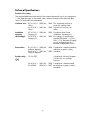
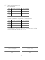
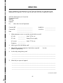
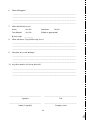
Service Manual
Type MFAC
High Impedance Differential Relays
Service Manual
Type MFAC
High Impedance Differential Relays
HANDLING OF ELECTRONIC EQUIPMENT
A person's normal movements can easily generate electrostatic potentials of several thousand volts.
Discharge of these voltages into semiconductor devices when handling electronic circuits can cause
serious damage, which often may not be immediately apparent but the reliability of the circuit will have
been reduced.
The electronic circuits of ALSTOM T&D Protection & Control Ltd products are completely safe from
electrostatic discharge when housed in the case. Do not expose them to the risk of damage by
withdrawing modules unnecessarily.
Each module incorporates the highest practicable protection for its semiconductor devices. However, if it
becomes necessary to withdraw a module, the following precautions should be taken to preserve the high
reliability and long life for which the equipment has been designed and manufactured.
1. Before removing a module, ensure that you are at the same electrostatic potential as the equipment
by touching the case.
2. Handle the module by its front-plate, frame, or edges of the printed circuit board.
Avoid touching the electronic components, printed circuit track or connectors.
3. Do not pass the module to any person without first ensuring that you are both at the same
electrostatic potential. Shaking hands achieves equipotential.
4. Place the module on an antistatic surface, or on a conducting surface which is at the same
potential as yourself.
5. Store or transport the module in a conductive bag.
More information on safe working procedures for all electronic equipment can be found in BS5783 and
IEC 60147-0F.
If you are making measurements on the internal electronic circuitry of an equipment in service, it is
preferable that you are earthed to the case with a conductive wrist strap.
Wrist straps should have a resistance to ground between 500k – 10M ohms. If a wrist strap is not
available, you should maintain regular contact with the case to prevent the build up of static.
Instrumentation which may be used for making measurements should be earthed to the case whenever
possible.
ALSTOM T&D Protection & Control Ltd strongly recommends that detailed investigations on the electronic
circuitry, or modification work, should be carried out in a Special Handling Area such as described in
BS5783 or IEC 60147-0F.
TYPES:
MFAC 14
MFAC 34
CONTENTS
SAFETY SECTION
5
1.
1.1
1.2
1.3
1.4
INSTALLATION
General
Unpacking
Storage
Site
9
9
9
9
9
2.
2.1
2.2
COMMISSIONING
Description of relay, calculation of setting and commissioning preliminaries
Instructions to ensure that the relay can be commissioned at the specific settings
for the application
10
10
3.
MAINTENANCE
18
4.
4.1
4.2
4.3
MECHANICAL SETTINGS
General
Contact settings
Mechanical flag settings
18
18
18
18
5.
5.1
5.2
PROBLEM ANALYSIS
Failure to operate
Output contacts not changing state
19
19
19
6.
SPARES
20
7.
COMMISSIONING TEST RECORD
21
REPAIR FORM
23
4
12
SAFETY SECTION
This Safety Section should be read before commencing any work on the equipment.
Health and safety
The information in the Safety Section of the product documentation is intended to
ensure that products are properly installed and handled in order to maintain them in
a safe condition. It is assumed that everyone who will be associated with the
equipment will be familiar with the contents of the Safety Section.
Explanation of symbols and labels
The meaning of symbols and labels which may be used on the equipment or in the
product documentation, is given below.
Caution: refer to product documentation
Caution: risk of electric shock
Protective/safety *earth terminal
Functional *earth terminal.
Note: this symbol may also be used for a protective/
safety earth terminal if that terminal is part of a
terminal block or sub-assembly eg. power supply.
*Note: The term earth used throughout the product documentation is the direct
equivalent of the North American term ground.
Installing, Commissioning and Servicing
Equipment connections
Personnel undertaking installation, commissioning or servicing work on this
equipment should be aware of the correct working procedures to ensure safety.
The product documentation should be consulted before installing, commissioning or
servicing the equipment.
Terminals exposed during installation, commissioning and maintenance may present
a hazardous voltage unless the equipment is electrically isolated.
If there is unlocked access to the rear of the equipment, care should be taken by all
personnel to avoid electric shock or energy hazards.
Voltage and current connections should be made using insulated crimp terminations
to ensure that terminal block insulation requirements are maintained for safety. To
ensure that wires are correctly terminated, the correct crimp terminal and tool for the
wire size should be used.
5
Before energising the equipment it must be earthed using the protective earth
terminal, or the appropriate termination of the supply plug in the case of plug
connected equipment. Omitting or disconnecting the equipment earth may cause a
safety hazard.
The recommended minimum earth wire size is 2.5 mm2, unless otherwise stated in
the technical data section of the product documentation.
Before energising the equipment, the following should be checked:
Voltage rating and polarity;
CT circuit rating and integrity of connections;
Protective fuse rating;
Integrity of earth connection (where applicable)
Equipment operating conditions
The equipment should be operated within the specified electrical and environmental
limits.
Current transformer circuits
Do not open the secondary circuit of a live CT since the high voltage produced
may be lethal to personnel and could damage insulation.
External resistors
Where external resistors are fitted to relays, these may present a risk of electric shock
or burns, if touched.
Battery replacement
Where internal batteries are fitted they should be replaced with the recommended
type and be installed with the correct polarity, to avoid possible damage to the
equipment.
Insulation and dielectric strength testing
Insulation testing may leave capacitors charged up to a hazardous voltage. At the
end of each part of the test, the voltage should be gradually reduced to zero, to
discharge capacitors, before the test leads are disconnected.
Insertion of modules and pcb cards
These must not be inserted into or withdrawn from equipment whilst it is energised,
since this may result in damage.
Fibre optic communication
Where fibre optic communication devices are fitted, these should not be viewed
directly. Optical power meters should be used to determine the operation or signal
level of the device.
6
Older Products
Electrical adjustments
Equipments which require direct physical adjustments to their operating mechanism to
change current or voltage settings, should have the electrical power removed before
making the change, to avoid any risk of electric shock.
Mechanical adjustments
The electrical power to the relay contacts should be removed before checking any
mechanical settings, to avoid any risk of electric shock.
Draw out case relays
Removal of the cover on equipment incorporating electromechanical operating
elements, may expose hazardous live parts such as relay contacts.
Insertion and withdrawal of extender cards
When using an extender card, this should not be inserted or withdrawn from the
equipment whilst it is energised. This is to avoid possible shock or damage hazards.
Hazardous live voltages may be accessible on the extender card.
Insertion and withdrawal of heavy current test plugs
When using a heavy current test plug, CT shorting links must be in place before
insertion or removal, to avoid potentially lethal voltages.
Decommissioning and Disposal
Decommissioning: The auxiliary supply circuit in the relay may include capacitors
across the supply or to earth. To avoid electric shock or energy
hazards, after completely isolating the supplies to the relay
(both poles of any dc supply), the capacitors should be safely
discharged via the external terminals prior to decommissioning.
Disposal:
It is recommended that incineration and disposal to water
courses is avoided. The product should be disposed of in a safe
manner. Any products containing batteries should have them
removed before disposal, taking precautions to avoid short
circuits. Particular regulations within the country of operation,
may apply to the disposal of lithium batteries.
7
Technical Specifications
Protective fuse rating
The recommended maximum rating of the external protective fuse for this equipment
is 16A, Red Spot type or equivalent, unless otherwise stated in the technical data
section of the product documentation.
Insulation class: IEC 61010-1: 1990/A2: 1995 This equipment requires a
Class I
protective (safety) earth
EN 61010-1: 1993/A2: 1995 connection to ensure user
Class I
safety.
Installation
Category
(Overvoltage):
IEC 61010-1: 1990/A2: 1995 Distribution level, fixed
Category III
installation. Equipment in
EN 61010-1: 1993/A2: 1995 this category is qualification
Category III
tested at 5kV peak, 1.2/50µs,
500Ω, 0.5J, between all supply
circuits and earth and also
between independent circuits.
Environment:
IEC 61010-1: 1990/A2: 1995 Compliance is demonstrated by
Pollution degree 2
reference to generic safety
EN 61010-1: 1993/A2: 1995 standards.
Pollution degree 2
Product safety:
73/23/EEC
Compliance with the European
Commission Low Voltage
Directive.
EN 61010-1: 1993/A2: 1995 Compliance is demonstrated
EN 60950: 1992/A11: 1997 by reference to generic safety
standards.
8
Section 1.
1.1
INSTALLATION
General
Protective relays, although generally of robust construction, require careful treatment
prior to installation and a wise selection of site. By observing a few simple rules the
possiblity of premature failure is eliminated and a high degree of performance can
be expected.
The relays are either despatched individually or as part of a panel/rack mounted
assembly in cartons specifically designed to protect them from damage.
Relays should be examined immediately they are received to ensure that no damage
has been sustained in transit. If damage due to rough handling is evident, a claim
should be made immediately to the transport company concerned and the nearest
ALSTOM T&D Protection & Control Ltd representative should be promptly notified.
Relays which are supplied unmounted and not intended for immediate installation
should be returned to their protective polythene bags.
1.2
Unpacking
Care must be taken when unpacking and installing the relays so that none of the
parts are damaged or their settings altered and must at all times be handled by
skilled persons only.
Relays should be examined for any wedges, clamps, or rubber bands necessary to
secure moving parts to prevent damage during transit and these should be removed
after installation and before commissioning.
Relays which have been removed from their cases should not be left in situations
where they are exposed to dust or damp. This particularly applies to installations
which are being carried out at the same time as constructional work.
1.3
Storage
If relays are not installed immediately upon receipt they should be stored in a place
free from dust and moisture in their original cartons and where de-humidifier bags
have been included in the packing they should be retained. The action of the dehumidifier crystals will be impaired if the bag has been exposed to damp ambient
conditions and may be restored by gently heating the bag for about an hour, prior to
replacing it in the carton.
Dust which collects on a carton may, on subsequent unpacking, find its way into the
relay; in damp conditions the carton and packing may become impregnated with
moisture and the de-humidifying agent will lose its efficiency.
The storage temperature range is –25° and +70°C.
1.4
Site
The installation should be clean, dry and reasonably free from dust and excessive
vibration. The site should preferably be well illuminated to facilitate inspection.
An outline diagram is normally supplied showing panel cut-outs and hole centres.
For individually mounted relays these dimensions will also be found in Publication
R6008.
Publication R7012 is a Parts Catalogue and Assembly Instructions. This document will
be useful when individual relays are to be assembled as a composite rack or panel
mounted assembly.
9
Publication R6001 is a leaflet on the modular integrated drawout system of protective
relays.
Publication R6014 is a list of recommended suppliers for the pre-insulated
connectors.
Section 2.
COMMISSIONING
2.1
Description of relay, calculation of setting and commissioning preliminaries
2.1.1
Description of MFAC 14/MFAC 34
This is a voltage operated relay having seven equally spaced settings of
15–185 volts, 25–175 volts, 25–375 volts or 100–400 volts which may be selected
by means of a plug bridge.
The relays may be used for any type of high impedance circulating current
protection.
2.1.2
List of abbreviations.
IE
IF
IFM
IP
IR
ISH
N
n
RCT
RL
RR
RSH
VF
VK
VP
VS
VR
2.1.3
= Current transformer exciting current at relay setting voltage (referred to the
CT secondary current)
= Maximum value of primary through fault current for which protection must
remain stable.
= Maximum value of primary fault current for internal fault.
= Primary current for operation of protection.
= Relay operating current.
= Current in shunt resistor at relay setting VR.
= Turns ratio of current transformer.
= No. of current transformers in parallel with relay.
= Secondary resistance of current transformer.
= Lead resistance between furthest current transformer and relay connection
point.
= Relay impedance.
= Value of shunt resistor.
= The theoretical voltage which would be produced across the relay circuit
under internal fault condition.
VF = IFM (RCT + 2RL + RR)
N
= Knee point voltage of current transformer.
= Peak voltage across relay circuit under maximum internal fault conditions.
= Minimum setting voltage. (calculated)
= Relay setting voltage.
Calculation of relay setting.
The minimum setting voltage to ensure stability is
VS
≥
IF (RCT + 2RL)
N
The relay plug setting voltage VR must be set to the nearest tap above VS.
10
The minimum knee point voltage must be
VK
≥
2VR
The operating current of the relay is 38mA, irrespective of tap selected, excluding the
current drawn by the external metrosil. When a standard metrosil is included with the
relay, the relay operating current including the metrosil is given in the table below.
It must be appreciated that metrosils have large tolerances and these figures are
given for guidance only.
a) Low range relay (5V steps)
15
Setting voltage VR
38
Relay current IR(mA)
(including metrosil, C = 450)
50
38
75
39
100 125 150 175 185
42 46 55 72 81
50
19
75
20
100 125 150 175
23 27 36 53
75
19
125 175 225 275 325
20 22 24 31 44
b) Low range relay
Setting voltage VR
25
Relay current IR(mA)
19
(including metrosil, C = 450)
c) High range relay
Setting voltage VR
25
Relay current IR(mA)
19
(including metrosil, C = 900)
d) 100–400V version
Setting voltage VR
100 150 200 250 300 350 400
Setting voltage IR(mA)
19 19 20 20 23 27 36
(including metrosil, C = 1100)
The primary current for operation is given by
IP = N (IR + nIE)
If the resultant value of IP is too low it may be increased by the addition of a shunt
resistor RSH to give a current of
ISH = VR
RSH
The new increased value of primary current
IP = N (IR + nIE + ISH)
External metrosils.
Each FAC relay is applied with an external metrosil which must be wired across the
relay circuit. This provides a shunt circuit for high internal fault currents and prevents
a high voltage being developed across the CT and relay circuits.
2.1.4
Commissioning preliminaries.
Inspection.
Carefully examine the module and case to see that no damage has occurred during
transit. Check that the relay serial number on the module, case and cover are
identical, and that the model number and rating information are correct.
Carefully remove any elastic bands/packing fitted for transportation purposes.
Carefully actuate the armature of each unit in turn with a small screwdriver/probe.
Note that immediately after the point where any normally open contacts just make
11
there is a small further movement of the armature. This ensures that contact follow
through and wiping action is present. On units fitted with hand reset flag indicators,
check the flag is free to fall before, or just as, any normally open contacts touch.
Check that the external wiring is correct to the relevant relay diagram or scheme
diagram. The relay diagram number appears inside the case.
Particular attention should be paid to the correct wiring and value of any external
resistors indicated on the wiring diagram/relay rating information.
Note that shorting switches shown on the relay diagram are fitted internally across
the relevant case terminals and close when the module is withdrawn. It is essential
that such switches are fitted across all CT circuits.
If a test block type MMLG is provided, the connections should be checked to the
scheme diagram, particularly that the supply connections are to the ‘live’ side of the
test block (coloured orange) and with terminals allocated with odd numbers (1, 3, 5,
7, etc.).
Earthing.
Ensure that the case earthing connection above the rear terminal block, is used to
connect the relay to a local earth bar.
Insulation.
The relay, and its associated wiring, may be insulation tested between:
a) all electrically isolated circuits
b) all circuits and earth
An electronic or brushless insulation tester should be used, having a dc voltage not
exceeding 1000V. Accessible terminals of the same circuit should first be strapped
together.
Deliberate circuit earthing links, removed for the tests, must subsequently be replaced.
Terminal allocation.
Terminals of the relay are normally allocated as below, but reference should always
be made to the relevant diagram.
a) Single pole relays
Normally open contacts 1, 3 and 2, 4.
AC current input – 27, 28.
An alternative version of the relay has additional normally open contacts
connected to 5, 7 and 6, 8.
b) Triple pole relays
Normally open contacts 1, 3 and 2, 4.
The contacts are normally connected in parallel for the three phases but a
version of the relay having contacts brought out separately is available.
AC current inputs - 23, 24 : 25, 26 : 27, 28.
2.2
Instructions to ensure that the relay can be commissioned at the specific settings for
the application
It is only necessary to check the relay at the setting on which it is to be used.
The relay must not be used at any setting other than that for which the setting has
been calculated.
12
2.2.1
Test equipment required
1 – Secondary injection test equipment capable of providing an ac voltage supply
of up to at least 120% of the relay setting.
1 – Multifinger test plug type MMLB 01 for use with test block type MMLG if fitted.
1 – Miniature split plug type MMLB 03 to fit relay plug bridge.
3 – Calibrated multimeters 0–10 amp ac, 0–400 volt ac.
1 – Set primary injection testing equipment.
2.2.2
General
If the relay is wired through an MMLG test block it is recommended that all
secondary injection tests should be carried out using this block.
Ensure that the main system current transformers are shorted before isolating the relay
from the current transformers in preparation for secondary injection tests.
DANGER:
DO NOT OPEN CIRCUIT THE SECONDARY CIRCUIT OF A CURRENT TRANSFORMER
SINCE THE HIGH VOLTAGE PRODUCED MAY BE LETHAL AND COULD DAMAGE
INSULATION.
When type MMLG test block facilities are installed, it is important that the sockets in
the type MMLB 01 test plug, which correspond to the current transformer secondary
windings, are LINKED BEFORE THE TEST PLUG IS INSERTED INTO THE TEST BLOCK.
Similarly, a MMLB 02 single finger test plug must be terminated with an ammeter
BEFORE IT IS INSERTED to monitor CT secondary currents.
It is assumed that the initial preliminary checks have been carried out.
2.2.3
Relay CT shorting switches
With the relay removed from its case, check electrically that the CT shorting switch is
closed.
2.2.4
Secondary injection testing
Connect the circuit as shown in Figure 1 and ensure that the current transformer
primary is open circuit and that if any earthing connections are fitted, they do not
short out the primaries of any current transformers.
Increase the voltage until the relay just operates.
Note the current in the relay (this can be done using the miniature split plug inserted
into the appropriate position of the plug bridge connected to an ammeter). It should
be approximately 38mA at setting.
Note also the voltage at which the relay operates which should correspond to the
setting VR of the relay with a tolerance of ±10%. The total secondary current for
operation will be given on ammeter A1. This test should be repeated for each pole of
the relay.
Drop off/Pick up ratio.
Check that this ratio is greater than 50%.
13
2.2.5
Primary injection testing
It is essential that primary injection testing is carried out to prove the correct polarity
of current transformers.
Before commencing any primary injection testing it is essential to ensure that the
circuit is dead, isolated from the remainder of the system and that only those earth
connections associated with the primary test equipment are in position.
2.2.6
Primary fault setting
The primary fault setting of any balanced scheme can be checked using the circuit
shown in Figure 2. The primary current is injected into each current transformer in
turn and increased until the relay operates. The voltage at which the relay operates
should be within ±10% of the relay setting voltage VR. The primary current for
operation and relay current should be noted.
In the case of machine protection similar tests must be carried out by injecting first
into each current transformer in turn to determine the primary fault setting.
For large machines the machine itself can be used to provide the fault current to
check the primary fault setting as shown in Figure 5. The machine should be run up
to speed with no excitation. The excitation should then be increased until the relays
have all operated. The primary current, relay current and relay voltage should be
noted as each relay operates.
2.2.7
Through fault stability
With any form of unbalanced protection it is necessary to check that the current
transformers are correctly connected. For this purpose with a restricted earth fault
scheme the circuit shown in Figure 3 may be used. During this test it is necessary to
measure the spill current in the relay circuit and short out the relay and stabilising
resistor (if fitted). The current is increased up to as near full load as possible and the
spill current noted. The spill current should be very low, only a few milliamps if the
connections are correct. A high reading (twice the injected current, referred through
the current transformer ratio) indicates that one of the current transformers is reversed.
Injection should be carried out through each phase to netural.
Where primary injection is not practicable in the case of restricted earth fault
protection on a transformer it may be possible to check stability by means of back
energising the transformer from a low voltage (415V) supply as shown in Figure 4.
In the case of machine protection, similar stability tests must be carried out by
injecting into one and out of another current transformer connected on the same
phase.
For large machines, the machine itself can be used to provide the fault current, but
the short circuit must now be fitted as shown in Figure 6. The machine should be
run up to normal speed and the excitation increased until the primary current is
approximately full load, when the spill current should be checked.
All other types of balanced protection should be tested in a similar manner.
At the conclusion of the tests ensure that all connections are correctly restored and
any shorting connections removed.
14
Relay
A2
Metrosil
Stabilising resistor (if fitted)
Ammeter
(in plug bridge circuit)
A1
V
Figure 1 Secondary injection of relay to check secondary operating current, setting voltage and relay
operating current.
A1
Primary injection
test set
V
A2
Stabilising resistor (if fitted)
Relay
Ammeter (in plug bridge circuit)
Figure 2 Sensitivity check of restricted earth fault scheme by primary injection.
15
A1
Primary injection
test set
A
B
C
Temporary connections
A2
Metrosil
Relay
Stabilising resistor (if fitted)
Figure 3 Stability check of restricted earth fault protection.
A1
A
B
LV
supply
C
Temporary short circuit
A2
Relay
Stabilising resistor (if fitted)
Figure 4 Stability check on restricted earth fault scheme by back energising with a low voltage supply.
16
Temporary short circuit
Isolating
links
Generator
A
B
C
V
87
87
87
87 Generator differential relay
V Voltmeter
Figure 5 Testing sensitivity of generator differential protection using generator to supply primary
current.
Isolating
links
Temporary short circuit
Generator
A
B
C
A2
A2
A2
87
87
87
87 Generator differential relay
A2 Ammeter
Figure 6 Checking stability of generator differential protection.
17
Section 3.
MAINTENANCE
Periodic maintenance is not necessary. However, periodic inspection and test is
recommended. This should be carried out every l2 months or more often if the relay is
operated frequently or is mounted in poor environmental conditions.
3.1
Repeat secondary injection tests 2.2.4 to prove operation, with emphasis on contact
wear and condition. Mechanical settings may be checked against those shown in
Section 4.
Section 4.
4.1
MECHANICAL SETTINGS
General
Armature gap measurements should be made with the top of the feeler gauge level
with the centre line of the core.
Contact pressures are measured with a gramme gauge at the contact tips.
In general contact gaps and follow through are defined by quoting an armature gap
at which the tips should be just closed or just open.
The relay contact state is always defined with the relay in the unenergised position,
unless otherwise specified on the appropriate circuit diagram.
4.1.1
With the armature closed the clearance between the back of the armature and the
back stop should be 0.003"/0.008".
4.1.2
Nominal armature gap open: 0.060" for all types.
Set screw in armature so that armature gap when closed is approximately
0.005"/0.010".
4.2
Contact settings
4.2.1
Normal duty make contacts
With the armature closed onto a 0.011" feeler gauge the make contacts should be
closed, but should be open using a 0.013" feeler gauge.
Contact settings
2 contacts
(MFAC 34)
4 contacts
(MFAC 14)
Force to just close the make
contacts
20/25 grams
15/20 grams
Force to just lift the fixed contact
off its support
15/20 grams
20/25 grams
Nominal contact gap 0.060"/0.080"
4.3
Mechanical flag settings
4.3.1
Settings for self reset units
MFAC l4/34
With the armature closed on to a 0.013" feeler gauge the flag should be free to fall,
but should not fall using an 0.018" feeler gauge. Adjustment is made to the catch
spring on the flag.
18
Section 5.
5.1
PROBLEM ANALYSIS
Failure to operate
Check diagram for correct input connections.
Check tap voltage; this is marked above or below the plug bridge on the front of the
module.
Note: with the plug removed the relay setting goes to the highest tap value.
Measure the input current at VS, this should be 38mA (excluding the metrosil).
Flag spring may be jammed between armature and core face, preventing armature
closure.
Check internal wiring for damage.
Check choke continuity - resistance 240 ohms ±15%.
Check resistor values - remove pcb from module and fold down to gain access to
board.
Setting range
15–185
Adjustable resistor
Capacitor
Relay coil
Setting range
25–175
25–327
Adjustable resistor RV1
Capacitor
Relay coil
Setting range
100–400
5.2
Resistors on PCB ZJ0038
R1 – R3
R5–R6
R7–R8
680Ω
680Ω
150Ω
0–1000Ω
3.3µF
190Ω
R9
120Ω
Resistors on PCB ZJ0038
R1 – R6
1.3KΩ
2.4KΩ
510Ω
C1 1.7µF ±5% 50Hz, 1.18µF ±5% 60Hz.
560Ω ±15%
Resistors on PCB ZJ0038
R1–R6
2.7KΩ
R9
3.9KΩ
Output contacts not changing state
Check output terminals with reference to appropriate diagram.
Operating pushrods not in position
Internal wiring damaged
Contamination of contacts
Contacts should be cleaned with the burnishing tool supplied in the relay tool kits.
On no account should knives, files or abrasive materials be used.
Check mechanical settings as per Section 4.
19
Section 6.
SPARES
When ordering spares, quote the full relay model number and any component
reference numbers, or briefly describe the parts required.
Should the need arise for the equipment to be returned to ALSTOM T&D Protection &
Control Ltd for repair, then the form at the back of this manual should be completed
and sent with the equipment together with a copy of any commissioning test results.
20
Section 7.
COMMISSIONING TEST RECORD
High Impedance Differential Relay Type MFAC
Date
Station
Circuit.
Relay Model No.
Serial No.
Setting range
CT ratio
Setting voltage
Relay setting
Type of ext. metrosil
Shunt resistor ohms
(if fitted)
Calculated primary
operating current
Test results
2.2.3
Relay CT shorting switch
2.2.4
Secondary voltage to operate relay.
Phase
Total current (A1)
Relay current (A2)
PU volts
DO volts
A
B
C
Drop off / pick up ratio check
2.2.6
Primary current to operate relay
Phase
Primary current (A1)
Relay current (A2)
A
B
C
N
21
Relay voltage
2.2.7
Stability check by primary injection
Restricted earth fault
Phases
Primary current (A1)
Spill current (A2)
A–N
B–N
C–N
Circulating current between two or more sets of current transformers.
Phases
Primary current (A1)
Spill current (A2)
A1–A2
B1–B2
C1–C2
Where more than two sets of current transformers are involved, injection should be
carried out between set 1 and each other set in turn.
Commissioning Engineer
Customer Witness
Date
Date
22
REPAIR FORM
Please complete this form and return it to ALSTOM T&D Protection & Control Ltd with the
equipment to be repaired. This form may also be used in the case of application queries.
ALSTOM T&D Protection & Control Ltd
St. Leonards Works
Stafford
ST17 4LX,
England
For:
After Sales Service Department
Customer Ref: ___________________________
Model No: __________________
Contract Ref:
___________________________
Serial No:
Date:
___________________________
1.
__________________
What parameters were in use at the time the fault occurred?
AC volts
_____________ Main VT/Test set
DC volts
_____________ Battery/Power supply
AC current
_____________ Main CT/Test set
Frequency
_____________
2.
Which type of test was being used? ____________________________________________
3.
Were all the external components fitted where required?
(Delete as appropriate.)
4.
List the relay settings being used
Yes/No
____________________________________________________________________________
____________________________________________________________________________
____________________________________________________________________________
5.
What did you expect to happen?
____________________________________________________________________________
____________________________________________________________________________
____________________________________________________________________________
____________________________________________________________________________
continued overleaf
✁
23
6.
What did happen?
____________________________________________________________________________
____________________________________________________________________________
____________________________________________________________________________
____________________________________________________________________________
7.
8.
When did the fault occur?
Instant
Yes/No
Intermittent
Yes/No
Time delayed
Yes/No
(Delete as appropriate).
By how long?
___________
What indications if any did the relay show?
____________________________________________________________________________
____________________________________________________________________________
____________________________________________________________________________
9.
Was there any visual damage?
____________________________________________________________________________
____________________________________________________________________________
____________________________________________________________________________
10. Any other remarks which may be useful:
____________________________________________________________________________
____________________________________________________________________________
____________________________________________________________________________
______________________________________
Signature
_______________________________________
Title
______________________________________
Name (in capitals)
_______________________________________
Company name
✁
24
25
26
27
A L S T O M T & D P r o t e c t i o n & C o n t r o l L t d St Leonards Works, Stafford, ST17 4LX England
Tel: 44 (0) 1785 223251 Fax: 44 (0) 1785 212232 Email: [email protected] Internet: www.alstomgpc.co.uk
©1998 ALSTOM T&D Protection & Control Ltd
Our policy is one of continuous product development and the right is reserved to supply equipment which may vary from that described.
Publication R8007E
Printed in England.