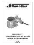
1
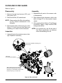
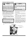
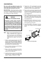
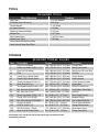
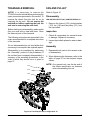
ZT-2800®
Integrated Zero-Turn Transaxle
Service and Repair Manual
BLN-52441
December 2008
Table Of Contents
Foreword ...................................................... 1
Hub Removal ............................................... 19
Description and Operation ............................ 2
Tear Down and Reassembly........................ 20
Introduction ................................................... 2
How To Use This Manual ............................. 20
Hydraulic Schematic ..................................... 3
General Instructions .................................... 20
External Features ......................................... 4
Tools ............................................................ 21
Technical Specifications ............................... 6
Torques ........................................................ 21
Product Identification .................................... 6
Transaxle Removal ...................................... 22
Safety ........................................................... 7
Fan and Pulley........................................ 22-24
Personal Safety ............................................ 7
Side Cover .................................................. 25
Tool Safety .................................................... 7
Bull, Pinion and Reduction Gears................ 26
Work Area Safety.......................................... 7
Charge Pump .............................................. 27
Servicing Safety............................................ 7
Input Shaft ................................................... 28
Troubleshooting ............................................ 8
Bypass Arm ................................................. 29
Service and Maintenance ............................. 9
Swashplate .................................................. 30
External Maintenance ................................... 9
Center Section ............................................. 31
Service and Maintenance Procedures.......... 9
Brake Assembly ...................................... 32-33
Fluids ............................................................ 9
Center Section Kit........................................ 34
Fluid Volume and Level ................................ 9
Check Plugs & Seals ................................... 35
Filter and Filter Guard................................. 10
Cylinder Blocks ............................................ 35
Fluid Change Procedure............................. 11
Axle Shaft .................................................... 36
Purging Procedures .................................... 12
Assembly After Complete Tear Down .......... 37
Return To Neutral Setting ........................... 13
Side Cover – Screw Tightening Sequence .. 38
Return To Neutral Assembly ....................... 14
How To Use Service Schematic .................. 39
Control Arm Assembly ................................ 15
ZT-2800® Transaxle Exploded View ............ 40
Parking Brake Adjustment .......................... 16
ZT-2800® Transaxle Parts List ..................... 41
Parking Brake Assembly............................. 17
Glossary Of Terms .................................. 42-43
Brake Arm Assembly .................................. 18
ZT-2800®
i
FOREWORD
Headquartered in Sullivan, Illinois, Hydro-Gear®
is a world leader in the design, manufacture,
and service of quality hydrostatic transaxles for
the lawn and garden industry. The mission of
our company is to be recognized by our customers and the industry as a world-class supplier
and the quality leader in everything we do.
Internal repair procedures require that the
transaxle unit be removed from the vehicle.
This Service and Repair Manual is designed
to provide information useful in servicing and
troubleshooting the Hydro-Gear ZT-2800 ®
Integrated Zero-Turn Transaxle.
This is not a certification, test or study guide for
a certification test. If a technician is interested in
certification, they should contact an agent representing EETC (Equipment & Engine Training
Council) at (262) 367-6700 or their Hydro-Gear
Central Service Distributor. Many distributors
will be hosting certification testing. These study
guides will cover most of the products and
manufacturers in our industry.
Also included is a glossary of terms that are
frequently used throughout the industry and in
Hydro-Gear service publications. Understanding terminology is very important!
For more information about Hydro-Gear or our
products, please contact your Central Service
Distributor, or call our Customer Service Department at (217) 728-2581.
It is necessary, and a good shop practice, that
your service area be equipped with the proper
tools and the mechanics be supplied the latest
information available. All repair procedures
illustrated in this guide are suggested, but preferred methods of repair.
ZT-2800®
1
DESCRIPTION AND OPERATION
Introduction
The purpose of this manual is to provide information useful in servicing the Hydro-Gear®
ZT-2800 ® Integrated Zero-Turn Transaxle.
This manual includes the ZT-2800’s general
descriptions, hydraulic schematics, technical
specifications, servicing and troubleshooting
procedures.
Other than recommended oil and filter changes,
the transaxle normally will not require servicing during the life of the vehicle in which it is
installed. Should other servicing be required,
the exterior of the transaxle will need to be
thoroughly cleaned before beginning most
procedures. Do not wash the transaxle while
it is hot. Do not use a pressure washer to
clean the unit.
General Description
The ZT-2800 is a self contained unit designed
for the transfer and control of power. It provides
an infinitely variable speed range between zero
and maximum in both forward and reverse
modes of operation.
This transaxle uses a variable displacement
pump with a maximum displacement of 10cc
per revolution, and motor with a fixed displacement of 16cc per revolution. The variable displacement pump features a trunnion
mounted swashplate with a direct-proportional
displacement control. Reversing the direction
of the swashplate reverses the flow of oil from
the pump and thus reverses the direction of the
motor output rotation. The pump and motor are
of the axial piston design and utilize spherical
nosed pistons which are held against a thrust
race by internal compression springs.
The ZT-2800 transaxle is fully flooded with oil.
A common external expansion tank assures the
drives’ cool, quiet operation. An external filter
provides ease of access for oil maintenance of
the drive for the estate and entry level profes2
sional vehicles. The ZT-2800 is designed for
both charged and uncharged product versions.
In the uncharged consumer vehicle drive, fluid
passes through the filter by interaction of the
positive head on the fluid from a properly elevated expansion tank and the negative pressure created at the pump inlet during piston
operation.
Hydro-Gear’s patented charge configuration is
used in the estate/professional version. Here,
fluid is drawn from the case and through the
filter and into a fixed displacement gerotor
pump. Charge pump flow not used to feed the
low pressure side of the system is passed over
a charge relief valve and back into the transaxle
case.
The check valves in the center section are used
to control the make-up flow of the fluid to the
low pressure side of the loop.
The ZT-2800 has an internal cog style parking
brake. It is essential to fully disengage the brake
prior to operation.
A cam style, block lifting bypass is utilized in
the ZT-2800 to permit moving the vehicle for a
short distance at a maximum of 2 m.p.h. (3.2
Km/h) without starting the engine. The brake
must be disengaged prior to actuating the bypass mechanism.
WARNING
Actuating the bypass will result in the
loss of hydrostatic braking capacity. The
machine must be stationary on a level
surface and in neutral when actuating
the bypass.
ZT-2800®
HYDRAULIC SCHEMATIC
Vent
Input Shaft
Case Reservoir
Bypass
Motor
Pump
Motor Shaft
System Check Valves
Filter
Charge Relief
Charge Pump
Figure 1, Hydraulic Schematic With Charge Pump
Vent
Input Shaft
Case Reservoir
Bypass
Pump
Motor
Motor Shaft
System Check Valves
Filter
Figure 2, Hydraulic Schematic Without Charge Pump
ZT-2800®
3
EXTERNAL FEATURES ZT-2800®
Axle Shaft
Parking Brake Shaft
Main Housing
Bypass Arm
Control Arm
— Top View —
Drain Port
(For Horizontal Installation)
Top Port Plug
Parking
Brake Arm
Side Cover
— Inboard View —
4
ZT-2800®
EXTERNAL FEATURES ZT-2800®
Input Shaft
Axle Shaft
Oil Filter
Expansion Port (For Horizontal Installation)
— Outboard View—Left (Standard Control) —
Fan and Pulley Kit
Return To Neutral Assembly
Charge Pump
— Outboard View—Right (Return To Neutral Control) —
ZT-2800®
5
TECHNICAL SPECIFICATIONS
ZT-2800 ® TECHNICAL SPECIFICATIONS
Overall Transaxle Reduction
20.69:1
24.74:1
27.23:1
Input Speeds
3000 rpm Non-Charge — 3600 rpm Charged
Maximum Hi-Idle (No Load)
1800 rpm
Minimum
Output Torque
Intermittent
300 lb-ft (406 N-m)
340 lb-ft (461 N-m)
370 lb-ft (502 N-m)
Continuous
160 lb-ft (217 N-m)
180 lb-ft (244 N-m)
200 lb-ft (270 N-m)
Maximum with 18” tires
400 lb (181 kg)
480 lb (217 kg)
540 lb (244 kg)
Maximum with 20” tires
360 lb (163 kg)
440 lb (199 kg)
480 lb (217 kg)
Maximum with 22” tires
—
400 lb (181 kg)
440 lb (199 kg)
Weight on Tires (per unit)
Axle Shaft Diameter
1.00 in (25.4 mm)
Axle Shaft End Options
Tapered 4–Bolt Flange
Parking Brake Type
Internal
32 lb (14.5 kg)
Weight of Unit
PRODUCT IDENTIFICATION
The model and configuration of the ZT-2800 can be determined from the label shown below.
HYDRO-GEAR
BOM Mo
del Num
ber
ilt
u
Year B
ZH-KCEE-1B8C-1BXX
5 186 B4 476
Date (Julian- Day of year)
ZH-KCEE-1B8C-1BXX
ing Number
Sales Draw
Assembled in USA
Serial Number (unique for that model - for that day)
Type of Product and Build Information
Figure 3, Configuration Label
6
ZT-2800®
SAFETY
This symbol points out important safety
instructions which, if not followed, could endanger the personal safety and/or property of
yourself and others. Read and follow all instructions in this manual before attempting maintenance on your transaxle. When you see this
symbol - HEED ITS WARNING.
Wear appropriate clothing. Loose or hanging
clothing or jewelry can be hazardous. Use the
appropriate safety equipment, such as eye
and hearing protection, and safety-toe and
slip-proof shoes.
Never use compressed air to clean debris from
yourself or your clothing.
Tool Safety
WARNING
POTENTIAL FOR SERIOUS INJURY
Inattention to proper safety, operation, or
maintenance procedures could result in
personal injury, or damage to the equipment. Before servicing or repairing the
ZT-2800® transaxle, fully read and understand the safety precautions described
in this section.
Personal Safety
Certain safety precautions must be observed
while servicing or repairing the ZT-2800. This
section addresses some of these precautions
but must not be considered an all-inclusive
source on safety information. This section is
to be used in conjunction with all other safety
material which may apply, such as:
1. Other manuals pertaining to this machine,
2. Local and shop safety rules and codes,
3. Governmental safety laws and regulations.
Use the proper tools and equipment for the
task.
Inspect each tool before use and replace any
tool that may be damaged or defective.
Work Area Safety
Keep the work area neat and orderly. Be sure
it is well lit, that extra tools are put away, trash
and refuse are in the proper containers, and dirt
or debris have been removed from the working
areas of the machine.
The floor should be clean and dry, and all extension cords or similar trip hazards should be
removed.
Servicing Safety
Certain procedures may require the vehicle to
be disabled in order to prevent possible injury
to the servicing technician and/or bystanders.
The loss of hydrostatic drive line power may
result in the loss of hydrostatic braking capability.
Be sure that you know and understand the
equipment and the hazards associated with it.
Do not place speed above safety.
Some cleaning solvents are flammable. Use
only approved cleaning materials: Do not use
explosive or flammable liquids to clean the
equipment.
Notify your supervisor whenever you feel there
is any hazard involving the equipment or the
performance of your job.
To avoid possible fire, do not use cleaning
solvents in an area where a source of ignition
may be present.
Never allow untrained or unauthorized personnel to service or repair the equipment.
Discard used cleaning material in the appropriate containers.
ZT-2800®
7
TROUBLESHOOTING
WARNING
Do not attempt any servicing or adjustments with the engine running.
Use extreme caution while inspecting
the drive belt assembly and all vehicle
linkage!
Follow all safety procedures outlined in
the vehicle owner’s manual.
In many cases, problems with the ZT-2800®
are not related to a defective transaxle, but are
caused by slipping drive belts, partially engaged
bypass valves, and loose or damaged control
linkages. Be sure to perform all operational
checks and adjustments outlined in Service and
Maintenance, before assuming the transaxle
is malfunctioning. The table below provides a
troubleshooting checklist to help determine the
cause of operational problems.
T RO U BLE S HOOT I NG CHE CKL I S T
Po s s ible Cau s e
Co r r e c t ive Ac t io n
U nit Op er at e s I n On e Dir e c t io n On l y
Control linkage bent or out of adjustment
Repair or replace linkage, Page 9
Drive belt slipping or pulley damaged
Repair or replace drive belt or pulley, Page 9
Ve hicle Doe s No t Dr ive /Tr a ck S t r a ig h t
Vehicle tires improperly inflated
Refer to vehicle manufacturer suggested pressure
Control linkage bent or out of adjustment
Repair or replace linkage, Pages 9 and 13
Bypass assembly sticking
Repair or replace bypass, Page 29
Brake Partially Engaged
Disengage Brake, Replace Broken or Missing Brake Return Spring
Un it I s No isy
Oil level low or contaminated oil
Fill to proper level or change oil, Page 11
Excessive loading
Reduce vehicle loading, Page 9
Loose parts
Repair or replace loose parts
Bypass assembly sticking
Repair or replace linkage, Page 9
Air trapped in hydraulic system
Purge hydraulic system, Page 12
Brake Partially Engaged
Disengage Brake, Replace Broken or Missing Brake Return Spring
Un it Ha s No /L ow Powe r
Engine speed low
Adjust to correct setting
Control linkage bent or out of adjustment
Repair or replace linkage, Page 9
Drive belt slipping or pulley damaged
Repair or replace drive belt or pulley, Page 9
Oil level low or contaminated oil
Fill to proper level or change oil, Page 11
Excessive loading
Reduce vehicle loading, Page 9
Bypass assembly sticking
Repair or replace linkage, Page 9
Air trapped in hydraulic system
Purge hydraulic system, Page 12
Brake Partially Engaged
Disengage Brake, Replace Broken or Missing Brake Return Spring
Un it I s Op e r at in g Ho t
Debris buildup around transaxle
Clean off debris, Page 20
Cooling fan damaged
Repair or replace cooling fan, Pages 22-24
Oil level low or contaminated oil
Fill to proper level or change oil, Page 11
Excessive loading
Reduce vehicle loading, Page 9
Air trapped in hydraulic system
Purge hydraulic system, Page 12
Brake Partially Engaged
Disengage Brake, Replace Broken or Missing Brake Return Spring
Tr a n sa x le L e a k s Oil
8
Damaged seals, housing, or gaskets
Replace damaged components
Air trapped in hydraulic system
Purge hydraulic system, Page 12
ZT-2800®
SERVICE AND MAINTENANCE
External Maintenance
Regular external maintenance of the ZT-2800®
should include the following:
1. Check the vehicle operator’s manual for the
recommended load ratings. Insure that the
current application does not exceed load
rating.
2. Check oil level in accordance with “Fluid
Change Procedure,” step 12. Refer to page
11.
3. Inspect the vehicle drive belt, idler pulley(s),
and idler spring(s). Insure that no belt slippage can occur. Slippage can cause low
input speed to the transaxle.
4. Inspect the vehicle control linkage to the
directional control arm on the transaxle. Also
insure that the control arm is securely fastened to the trunnion arm of the transaxle.
5. Inspect the bypass mechanism on the
transaxle and the vehicle linkage to insure
that both actuate and release fully.
Service and Maintenance Procedures
Some of the service procedures presented on
the following pages can be performed while the
ZT-2800 is mounted on the vehicle. Any repair
procedures as mentioned in the repair section
of this manual must be performed after the unit
has been removed from the vehicle.
Typically, an engine oil with a minimum rating
of 9.0 cSt (55 SUS) at 230° F (110° C) and an
API classification of SL is recommended. A
20W50 engine oil has been selected for use
by the factory and is recommended for normal
operating procedures.
Fluid Volume and Level
Fluid volume information is provided in
the table below. Total system volume will depend on expansion tank size, hose length and
transaxle volume.
Certain situations may require additional fluid
to be added or even replaced. Refer to page 10
and figure 5 for the proper fill port location.
Recheck the fluid level once the unit has been
operated for approximately 1 minute.
Purging will be required if oil has been changed.
Refer to the purging procedures on page 12.
Fluid Description
20W50 engine oil
Component
Volume
Transaxle (bottom of fill port)
2284 ml (77.23 fl. oz.)
Expansion Tank (cold fill line)
40-82 ml (1.35-2.77 fl. oz.)
Hose (0.5″ I.D.)
38.60 ml (1.31 fl. oz.) / ft.
Fluids
The fluids used in Hydro-Gear products have
been carefully selected, and only equivalent, or
better products should be substituted.
ZT-2800®
9
FILTER AND FILTER GUARD
Refer to Figure 4
Disassembly
Assembly
1. Remove the hex head screws (105), and
filter guard (106).
1. Reassemble all parts in the reverse order
of disassembly.
2. Remove the filter (23) and discard.
2. When tightening the fasteners, refer to the
table on page 21 for the required torque
values.
NOTE: Always replace the filter when performing any internal maintenance to the
transaxle.
3. Remove the metal oil drain plug (5) or the
fitting (111) from inlet port and allow any
remaining oil to drain from the transaxle.
Inspection
3. Fill transaxle with oil. Refer to “Fluid Change
Procedures,” page 11, steps 3 and 4 for filter
change instructions.
NOTE: As a general rule, use the low end of
the torque specification on fasteners
when reassembling the unit.
1. Inspect all parts for excessive wear or damage. Replace if necessary.
111
Units will have installed, the fitting (111)
or the plug (5).
23
5
Drain port
(for horizontal installation)
11
106
When refilling the transaxle with oil,
remove the port plug (5), if installed,
and plug (11). Fill until the oil reaches the
lower lip of port (11) on side cover.
105
Figure 4, Filter and Guard
10
ZT-2800®
FLUID CHANGE PROCEDURE
This transaxle is designed with an external filter
for ease of maintenance. To ensure constant
fluid quality levels and longer life, an initial oil
and filter change at 75-100 hours, then every
400 hours thereafter is recommended.
The following procedure can be performed
with the transaxles installed in the vehicle, and
the vehicle on level ground. Apply the bypass
valve for each transaxle and lock the vehicle
parking brake.
1. Remove the three 1/4” filter guard screws
and filter guard. Clean any loose debris from
around the perimeter of the filter. See figures
4 and 5.
2. Place an oil drain pan (12” or more diameter and 8 qt. capacity is optimal) beneath
the oil filter. Remove the oil filter from the
transaxle.
3. After the oil has drained, wipe the filter base
surface off and apply a film of new oil to the
gasket of the new replacement filter (HydroGear part number 52114).
4. Install the new filter by hand, turn 3/4 to one
full turn after the filter gasket contacts the
filter base surface.
5. Re-install the filter guard with three 1/4”
screws. Torque screws to 65 in. lbs.
(7.3 Nm) each.
6. Repeat steps 1-5 on the opposite side
transaxle drive.
7. Drain old oil filters of all free flowing oil prior
to disposal. Place used oil in appropriate
containers and deliver to an approved recycling collection facility.
8. Remove the top port plug (figure 6) from the
left side and right side transaxles prior to
filling with oil. This will allow the transaxles
to vent during oil fill.
9. Remove the cap from the transaxle’s expansion tank located on the vehicle frame.
10. Fill with 20W50 motor oil until oil just appears at the bottom of each transaxle’s top
port (approximately 2 qts. per transaxle, 4
qts. total). Install the top port plug into each
transaxle as the oil level reaches this port.
11. Install and torque the top port plugs to 180
in. lbs. (20.3 Nm).
12. Continue to fill the transaxles through the
expansion tank until the “Full Cold” line is
reached on the Hydro-Gear expansion tank
(refer to vehicle owner’s manual for specific
volumes).
13. Re-install the expansion tank cap by hand.
Be careful to not overtighten.
14. Proceed to the purge procedure.
Top Port Plug
Filter
Filter Guard
Filter
(Guard Removed For Visual Clarity)
Figure 5, Filter Location
ZT-2800®
Screws
Figure 6, Filter And Filter Guard
11
PURGING PROCEDURES
Due to the effects air has on efficiency in hydrostatic drive applications, it is critical that it is
purged from the system.
Air creates inefficiency because its compression and expansion rate is higher than that of
the oil approved for use in hydrostatic drive
systems.
The following procedures are best performed
with the vehicle drive wheels off the ground.
Then repeated under normal operating conditions. If this is not possible, then the procedure
should be performed in an open area free of
any objects or bystanders.
1. Disengage the brake if activated.
These purge procedures should be implemented any time a hydrostatic system has been
opened to facilitate maintenance or the oil has
been changed.
2. With the bypass valve open and the engine
running, slowly move the directional control
in both forward and reverse directions (5 or
6 times).
The resulting symptoms in hydrostatic systems
may be:
3. With the bypass valve closed and the engine
running, slowly move the directional control
in both forward and reverse directions (5 to
6 times). Check the oil level, and add oil as
required after stopping the engine.
1. Noisy operation.
2. Lack of power or drive after short term operation.
3. High operation temperature and excessive
expansion of oil.
Before starting, make sure the transaxle is at
the proper oil level. If it is not, fill to the specifications outlined in this manual.
12
4. It may be necessary to repeat Steps 2 and
3 until all the air is completely purged from
the system. When the transaxle operates
at normal noise levels and moves smoothly
forward and reverse at normal speeds, then
the transaxle is considered purged.
ZT-2800®
RETURN TO NEUTRAL SETTING
WARNING
WARNING
POTENTIAL FOR SERIOUS INJURY
Do not attempt any servicing or adjustments with the engine running.
Use extreme caution while inspecting
the drive belt assembly and all vehicle
linkage!
Inattention to proper safety, operation, or
maintenance procedures could result in
personal injury, or damage to the equipment. Before servicing or repairing the
ZT-2800® transaxle, fully read and understand the safety precautions described
in this section.
Follow all safety procedures outlined in
the vehicle owner’s manual.
The return to neutral mechanism on the
transaxle is designed to set the directional
control into a neutral position when the operator
releases the vehicle hand control. Follow the
procedures below to properly adjust the return
to neutral mechanism on the transaxle:
3. Start the engine and increase the throttle to
full engine speed.
1. Confirm the transaxle is in the operating
mode (bypass disengaged). Raise the
vehicle’s drive tires off the ground to allow
free rotation.
5. Stop the vehicle’s engine. Reattach and
adjust the vehicle’s linkage according to the
vehicle owner’s manual.
NOTE: It may be necessary to remove the
drive tire from the axle hub to access the
linkage control and the transaxle return arm.
Remove the wheel by removing the lug nuts.
Do not remove the axle/hub nut.
2. Remove the Original Equipment Manufacturer’s (OEM’s) control linkage at the control
arm.
ROTATION "B"
4. Check for axle rotation. If the axle does not
rotate, go to Step 5. If the axle rotates, go
to Step 6.
6. Note the axle directional movement. Stop
the vehicle engine. Loosen the RTN adjustment screw until the control arm can
be rotated. Rotate the control arm in the
opposite direction of the axle rotation in 5
degree increments. Tighten the RTN adjustment screw. Recheck according to steps 3
and 4. Refer to Figure 7.
ROTATION "A"
RTN Adjusting Screw
Speed and Direction
Control Arm
Figure 7, Return to Neutral Setting
ZT-2800®
13
RETURN TO NEUTRAL ASSEMBLY
Refer to Figure 8
Disassembly
Assembly
1. Remove all items previously discussed in
their recommended order.
1. Reassemble all parts in the reverse order
of disassembly.
2. Remove the RTN control arm kit (211) by
first removing the spring (147) and Torx
head screw (46). The remaining members
of the assembly can be removed as a single
item – washer (146), unidirectional scissor
arm kit (145), and the control arm (44).
2. When tightening the fasteners, refer to the
table on page 21 for the required torque
values.
3. Refer to the RTN adjustments on page
13.
NOTE: As a general rule, use the low end of
the torque specification on fasteners
when reassembling the unit.
3. Remove the Allen head screw (142), washer
(45), neutral arm (141) and spacer (140).
NOTE: Only remove the seal (41) if damaged
or worn. The seal is not part of the
RTN control arm kit (211), and cannot
be serviced separately. Refer to “Seal
Kit” in the Items List on page 41.
Inspection
46
1. Inspect all parts for excessive wear or damage. Replace if necessary.
146
211
145
44
142
45
141
140
147
41
REFER TO “RETURN TO NEUTRAL SETTING”
ON PAGE 13.
Figure 8, Return to Neutral Assembly
14
ZT-2800®
CONTROL ARM ASSEMBLY
Refer to Figure 9
Disassembly
Assembly
1. Remove all items previously discussed in
their recommended order.
1. Reassemble all parts in the reverse order
of disassembly.
2. Remove the lock nut (47), the washer (45)
and the Torx head screw (46).
2. When tightening the fasteners, refer to the
table on page 20 for the required torque
values.
3. Remove the control arm (44), the washers
(43) and the stud (42).
NOTE: Only remove the seal (41) if damaged
or worn. The seal cannot be serviced
separately. Refer to “Seal Kit” in the
Items List on page 41.
NOTE: As a general rule, use the low end of
the torque spec on fasteners when
reassembling the unit.
Inspection
1. Inspect all parts for excessive wear or damage. Replace if necessary.
44
45
47
43
42
46
41
Figure 9, Control Arm Assembly
ZT-2800®
15
PARKING BRAKE ADJUSTMENT (Code 1 or 2)
Character #7 in the model number code = 1
or 2.
Example: ZX-XXXX-1XXX-XXXX
4. While holding the parking brake handle
(102) firmly onto the splines, remove clip
(103) from the shaft tip.
5. Before removing the parking brake handle
(102) scribe a reference mark between the
handle and shaft tip (101).
WARNING
POTENTIAL FOR SERIOUS INJURY
When servicing the parking brake on
unlevel terrain, it is essential to chock
the vehicle wheels to prevent vehicle
movement.
It should not be necessary to adjust the transaxle
parking brake over the life of the vehicle. In the
event that the transaxle parking brake does not
hold per vehicle manufacturer’s specifications,
the parking brake can be adjusted by rotating
the handle (102).
1. Note orientation of the vehicle parking brake
and linkage in the activated (locked) position.
2. Disengage the brake.
3. Detach the vehicle parking brake linkage
from the parking brake handle (102).
6. Remove the brake handle (102) far enough
to rotate the handle one tooth in the angular
direction opposite the brake handle’s actuated position.
7. Attach the retaining clip (103) to the brake
cam shaft.
8. Connect the vehicle parking brake linkage
to the brake handle (102).
9. Test the parking brake to assure it meets
the vehicle manufacturer’s specifications.
10. It is also important to assure that the parking brake is not partially engaged while the
vehicle is in the normal drive mode. This
can be confirmed by moving the vehicle to
level ground, turning the engine off, disengaging the brake, engaging the bypass and
assuring that the vehicle can be moved by
pushing with reasonable effort.
Brake (Cam) Shaft (101)
Brake Handle (102)
Reference Mark
Clip (103)
Brake (Cam) Shaft (101)
Figure 10, Brake Handle Orientation
16
Brake Handle (102)
Figure 11, Brake Handle Removal
ZT-2800®
PARKING BRAKE ASSEMBLY (Code 1 or 2)
Character #7 in the model number code = 1
or 2.
Inspection
Example: ZX-XXXX-1XXX-XXXX
1. Inspect all parts for excessive wear or damage. Replace if necessary.
Refer to Figure 12
2. Inspect the splines on the handle and brake
cam shaft.
Disassembly
1. Mark the position of the cam stop retainer
(104) in relation to the side cover (2).
NOTE: The orientation of the cam stop and
brake-cam to one another is very important. Indicate their relationship to
each other on the side cover to assist
in their correct assembly. See Insert
below.
2. Remove the retaining clip (103).
Assembly
1. Reassemble all parts in the reverse order
of disassembly.
2. When tightening the fasteners, refer to the
table on page 21 for the required torque
values.
NOTE: As a general rule, use the low end of
the torque specification on fasteners
when reassembling the unit.
3. Mark the position of the brake (cam) shaft
(101) in relation to the brake handle (102).
4. Remove the brake handle (102).
5. Remove the hex head screws (105) and the
cam stop retainer (104).
Brake-Cam
Shaft
(101)
Cam Stop
Retainer
(104)
ORIENTATION
Cam Stop Retainer (104)
105
102
Side Cover (2)
103
Brake (Cam) Shaft (101)
Figure 12, Parking Brake
ZT-2800®
17
BRAKE ARM ASSEMBLY (Code 3)
Character #7 in the model number code = 3
Inspection
Example: ZX-XXXX-3XXX-XXXX
1. Inspect all parts for excessive wear or damage. Replace if necessary.
Refer to Figure 13
Disassembly
2. Inspect the splines on the brake arm and
brake shaft.
1. Mark the position of the brake arm (102) in
relation to the brake shaft (101).
Assembly
NOTE: The orientation of the brake arm and
brake shaft to one another is very important.
1. Reassemble all parts in the reverse order
of disassembly.
2. Remove the retaining clip (103).
3. Remove the brake arm (102).
Brake Arm (102)
Reference Mark
Brake Shaft (101)
Brake Shaft (101)
102
103
Figure 13, Parking Brake
18
ZT-2800®
HUB REMOVAL
Do not use this procedure to remove the
drive wheel from the transaxle. Remove the
drive wheel by removing the lug nuts.
5. Tighten the 1-1/8” socket head center bolt
evenly and slowly. Note: This pressure will
separate the hub from the tapered axle.
DESCRIPTION: Follow the directions below
for removal of 4 bolt flanged hubs from tapered
axle shafts to facilitate maintenance to bearings, bushings and seals externally.
6. Remove the lug nuts and separate the hub
removal tool from the flanged hub and discard the “old” flanged hub and replace with
a new flanged hub.
WARNING
7. Refer to the appropriate manual / schematics for parts, repair procedures and proper
torque during reassembly of the flanged hub
to the tapered axle.
POTENTIAL FOR SERIOUS INJURY
Inattention to proper safety, operation,
or maintenance procedures could result in personal injury, or damage to the
equipment. Before servicing or repairing
the transaxle, fully read and understand
the safety precautions described in the
transaxle Service and Repair manual that
pertains to the specific transaxle to be
repaired.
8. Install wheel and rim and torque lug nuts.
Reference applicable vehicle service manual for proper lug nut torque.
9. Lower the vehicle to the ground, remove
chocks. Note: Brake will still be in engaged
mode.
Hub Retaining Nut
Flanged Hub
Note:
Before using the Hub Removal Tool
(Hydro - Gear P/N 71241), apply a thin
coat of anti-seize to the bolt threads.
Thread the bolt in and out of the Hub
Puller prior to using it for the first
time.
1. With the vehicle engine placed in the “OFF”
position, chock the front wheels, engage the
parking brake. Raise the vehicle drive tires
off the ground and remove the lug nuts from
the vehicles’ drive wheel/hub studs.
Axle Shaft (94)
Lug Nut
Figure 14, Hub Assembly
2. Remove the hex retaining nut (3/4-16) from
the center of the axle hub.
3. Back out the hub removal tool bolt with a
1-1/8” socket before installing the hub removal tool to the axle hub.
4. Insert the hub removal tool over the flange
wheel hub studs. Install lug nuts and secure
evenly. Torque to 100 lb-in. (11.3 Nm).
ZT-2800®
19
TEAR DOWN AND REASSEMBLY
How to Use This Manual
Each subassembly illustrated in this manual is
illustrated with an exploded view showing the
parts involved. The item reference numbers
in each illustration are for assembly instructions only. See page 41 for part names and
descriptions. A complete exploded view and
item list of the transaxle is provided at the end
of the repair section.
General Instructions
Cleanliness is a primary means of assuring
satisfactory life on repaired units. Thoroughly
clean all exposed surfaces prior to any type
of maintenance. Cleaning of all parts by using a solvent wash and air drying is usually
adequate. As with any precision equipment,
all parts must be kept free of foreign material
and chemicals.
Upon removal, it is recommended that all seals,
O-rings, and gaskets be replaced. During
installation lightly lubricate all seals, O-rings
and gaskets with a clean petroleum jelly prior
to assembly. Also protect the inner diameter of
seals during installation by covering the shaft
with a cellophane or plastic wrap material. Be
sure all remnants of this covering are removed
after servicing.
Parts requiring replacement must be replaced
from the appropriate kits identified in the Items
Listing, found at the end of this manual. Use
only original Hydro-Gear replacement parts
found in BLN-51427 (CD).
IMPORTANT: When internal repair is performed on the ZT-2800® transaxle, the oil filter
must be replaced.
Protect all exposed sealing surfaces and open
cavities from damage and foreign material. The
external surfaces should be cleaned before
beginning any repairs. Do not use a pressure
washer to clean the transaxle.
20
ZT-2800®
TOOLS
R E QUIRED TOOL S
Miscellaneous
Hub Puller
Flat Blade Screw Driver (2)
Torque Wrench
Air Impact Wrench
Rubber or Neoprene Mallet
Breaker Bar
Side Cutters/Snips
Needle Nose Pliers
Large External Snap Ring Pliers
Small Internal Snap Ring Pliers
Sockets
1/2”-3/8” Adapter
3/8” Deep
1-1/8” Deep
1/4” Allen
3/4” Deep
9/16” Deep
T-40 Torx Head
7/8” Deep
TORQUES
R E Q U I R ED TORQUE VAL UES
Item
Description
Torque
Operation
5
7
11
23
24
25
27
42
46
47
99
105
111
122
123
134
142
142
Plug 9/16-18 (Metal)
Screw, Hex head 1/4-20 x 1.25”
Plug, 9/16-18 (Metal)
Filter
Check Plug or Shock Valve
Check Plug or Shock Valve
Screw, Hex Head 3/8-16 x1.5
Stud, Short 5/16-24
Torx Head Screw 5/16-24 x 1.00
Nut, Hex Lock 5/16-24 UNF
Nut, Hex Lock 3/4-16
Screw, Hex Head 1/4-20 x .75
Fitting, STR 9/16-18 SAE
Nut, Hex Locking 1/2-20 Nylon
Screw, Hex Head
HFHCS 1/4-20 x .75
SHCS 5/16-24 x 1 Patch
Stud, 5/16-24 Friction Pack
180 – 240 lb-in (20.3 - 27.1 Nm)
105 – 155 lb-in (11.8 - 17.5 Nm)
180 – 240 lb-in (20.3 - 27.1 Nm)
130 – 150 lb-in (14.7 - 16.9 Nm)
280 – 400 lb-in (31.6 - 45.2 Nm)
280 – 400 lb-in (31.6 - 45.2 Nm)
525 – 700 lb-in (59.3 - 79.1 Nm)
50 – 120 lb-in (5.6 - 13.5 Nm)
230 – 310 lb-in (25.9 - 35.0 Nm)
85 – 120 lb-in (9.6 - 13.5 Nm)
180 – 200 lb-ft (244 - 271 Nm)
65 – 95 lb-in (7.3 - 10.7 Nm)
180 – 240 lb-in (20.3 - 27.1 Nm)
360 – 520 lb-in (40.6 - 58.7 Nm)
50 – 80 lb-in (5.6 - 9.0 Nm)
65 – 95 lb-in (7.3 - 10.7 Nm)
175 – 200 lb-in (19.7 - 22.6 Nm)
50 – 65 lb-in (5.6 - 7.3 Nm)
Oil Input Port
Side Cover Screws
Side Cover, Oil Level Port
Oil Filter
Center Section
Center Section
Center Section Screws
Control Arm
RTN/FR Control Arm
Control Arm, Short Stud
Hub Nut
Filter Guard Screws
Breather Fitting
Fan to Input Shaft Nut
Fan to Pulley Assembly
Charge Plate Screws
Neutral Arm Screw
Friction Pack Stud
As a general rule, use the low end of the torque spec on fasteners when
reassembling the unit.
ZT-2800®
21
TRANSAXLE REMOVAL
FAN AND PULLEY
NOTE: It is necessary to remove the
ZT-2800® from the vehicle before performing the
repair procedures presented in this section. To
remove the wheel from the hub, do so by
removing the lug nuts. Do not remove the
axle/hub nut unless replacing the hub, the
axle seal or removing the axle shaft.
Refer to Figure 15
Before starting any disassembly, make certain
that your work area is neat and clean. Clean
the external parts of the transaxle.
The following procedures are presented in the
order recommended for a complete tear down
of the transaxle.
Do not disassemble the unit any farther than
necessary to accomplish the required repairs.
Reassembly is accomplished by performing
the “Assembly” portions of the procedures. If
the unit has been completely disassembled, a
summary of the assembly procedures, in the
order in which they should occur, is given on
page 37.
122
123
Disassembly
FAN AND PULLEY KIT (207) CONFIGURATION “A”
1. Remove the locknut (122), slotted washer
(123), fan (120) and the pulley (121) from
the input shaft.
Inspection
1. Check all components for excessive wear
or damage. Replace if necessary.
2. Inspect input shaft splines for wear or damage.
Assembly
1. Reassemble all parts in the reverse order
of disassembly.
2. When tightening the fasteners, refer to the
table on page 21 for the required torque
values.
NOTE: As a general rule, use the low end of
the torque specification on fasteners
when reassembling the unit.
120
121
Figure 15, Fan/Pulley Kit (207) Configuration “A”
22
ZT-2800®
FAN AND PULLEY (Continued)
Refer to Figure 16
Refer to Figure 17
FAN AND PULLEY KIT (207) CONFIGURATION “B”
FAN AND PULLEY KIT (207) CONFIGURATION “C”
1. Remove the locknut (122), and detach the
fan and pulley assembly from the input
shaft.
1. Remove the locknut (122) and detach the
fan and pulley assembly from the input
shaft.
2. Separate the assembly by removing the
screws (123), fan (120) and the pulley
(121).
2. Remove the hex head screws (123) to
separate the fan (120) and pulley (121) assembly.
Inspection
Inspection
1. Check all components for excessive wear
or damage. Replace if necessary.
1. Check all components for excessive wear
or damage. Replace if necessary.
Assembly
Assembly
1. Reassemble all parts in the reverse order
of disassembly.
1. Reassemble all parts in the reverse order
of disassembly.
2. When tightening the fasteners, refer to the
table on page 21 for the required torque
values.
2. When tightening the fasteners, refer to the
table on page 21 for the required torque
values.
NOTE: As a general rule, use the low end of
the torque specification on fasteners
when reassembling the unit.
122
122
123
121
120
120
121
123
Figure 16, Fan/Pulley Kit (207) Configuration “B”
Figure 17, Fan/Pulley Kit (207) Configuration “C”
ZT-2800®
23
FAN AND PULLEY (Continued)
Refer to Figure 18
Disassembly
FAN AND PULLEY KIT (207) CONFIGURATION “D”
1. Remove the locknut (122), slotted washer
(123), pulley (121), fan (120) and pulley disc
(121) the from the input shaft.
Inspection
1. Check all components for excessive wear
or damage. Replace if necessary.
2. Inspect input shaft splines for wear or damage.
Assembly
1. Reassemble all parts in the reverse order
of disassembly.
2. When tightening the fasteners, refer to the
table on page 21 for the required torque
values.
NOTE: As a general rule, use the low end of
the torque specification on fasteners
when reassembling the unit.
122
123
124
120
121
Figure 18, Fan/Pulley Kit (207) Configuration “D”
24
ZT-2800®
SIDE COVER
Refer to Figure 19
Disassembly
Inspection
1. Remove all external items previously discussed in their recommended order.
1. Inspect the bearing and bushing areas in the
side cover for excessive wear or damage.
Replace if necessary.
2. Remove filter (23) and discard. Drain oil
from transaxle. Refer to page 11.
Assembly
3. Remove the screws (7), separate side cover
(2) from main housing (1), using “pry points”
as required.
1. Apply a bead of sealant around the perimeter of the main housing face. See “Sealant
Application Diagram” on page 37.
4. Remove the bearing (93) from side cover
(2).
2. Install the locating pins, if not already installed.
5. Remove the spacer (92) from axle (94).
3. Install the side housing (2). Use care not to
smear the sealant bead.
6. Clean off all the old sealant from the cover
(2) and the main housing (1). Take care
not to damage the sealing surfaces. A wire
brush and solvent is effective.
IMPORTANT: Before scraping the old sealant from the main housing, place a protective
cover over the internal parts of the transaxle;
avoiding any debris from entering the housing.
4. Install the side housing screws (7). Refer to
the screw tightening pattern on page 38.
5. When tightening the fasteners, refer to the
table on page 21 for the required torque
values.
1
94
Pry Point
Locating pin
2
92
93
Pry Point
7
Locating pin
Stuff a clean rag in the center section
oil filter passage before scraping the
sealant off the center section. This is to
prevent any sealant from getting into the
oil passage.
Figure 19, Side Cover
ZT-2800®
25
BULL, PINION AND REDUCTION GEARS
Refer to Figure 20
Disassembly
Assembly
1. Remove external items beginning on page
22.
1. Install the washer (74), pinion gear (72),
and secure their placement with retaining
ring (71) onto the motor shaft (73).
2. Remove washer (80) and reduction gear
set (81-82) as an assembly and set aside.
Remove second washer (80) and jack shaft
pin (83).
3. Remove the washer (70), retaining ring (71),
pinion gear (72) and washer (74) from the
motor shaft (73).
4. Remove the bull gear (91).
2. Install the washer (70) onto the motor shaft
(73).
3. Install the bull gear (91) onto the axle
(94).
4. Install the jack shaft pin (83), washer (80),
reduction gears (82) and (81).
5. Install washer (80) to jack shaft pin (83).
Inspection
1. Inspect the bull gear (91) – teeth and internal
splines, for wear or damage.
2. Separate the reduction gears and inspect
the gears and jack shaft pin for excessive
wear or damage. Replace if necessary.
94
91
80
83
81
82
80
74
70
71
72
Motor Shaft (73)
Figure 20, Bull, Reduction and Pinion Gear
26
ZT-2800®
CHARGE PUMP
Refer to Figures 21-21a
Disassembly
1. Mark the orientation of the charge pump
cover relative to the main housing, prior to
removal. Refer to figure 21.
2. Remove the hex head screws (134), charge
pump cover, gerotor assembly, and the Oring (132). Remove the connecting tubes
(130) at this point – only if the center section
will be removed. A pick type tool can be used
to remove the connection tubes.
3. When tightening the fasteners, refer to the
table on page 21 for the required torque
values.
NOTE: As a general rule, use the low end of
the torque specification on fasteners
when reassembling the unit.
Inspection
1. Inspect the gerotor assembly for wear or
damage. Replace if necessary.
Assembly
1. Reassemble all parts in the reverse order
of disassembly.
NOTE: When reinstalling the charge pump
components, replace the O-ring (132)
Also replace the connecting tubes
(130), if they have been removed.
130
132
2. Align the mark on the charge pump cover,
from step 1, Disassembly, with the mark on
the main housing.
Gerotor
Charge Pump Cover
203
Charge Pump Cover
Main Housing
134
Figure 21a, Charge Pump
Mark
Figure 21, Charge Pump Cover Orientation
ZT-2800®
27
INPUT SHAFT
Refer to Figure 22
Disassembly
Assembly
1. Requires removal of all items beginning on
page 22.
1. Reassemble all parts in the reverse order
of disassembly.
2. Remove the retaining ring (57).
3. Remove the lip seal (56) and discard.
4. Remove the washer (55) and the pump shaft
assembly (52–53).
NOTE: To assist in the removal of the pump
shaft, lightly tap (using a neoprene
head hammer) the shaft from the
charge pump side of housing. Care
should be taken not to damage the
shaft or gerotor running surface.
57
56
55
54
53
52
Remove the bearing from pump shaft
only if worn or damaged.
5. Remove the wire ring retainer (54) and the
bearing (53) from the pump shaft (52).
Inspection
1. Inspect the bearing and input shaft for wear
or damage. Inspect the splines on the shaft
for possible damage. Replace if necessary.
Figure 22, Input Shaft
28
ZT-2800®
BYPASS ARM
Refer to Figure 23
Disassembly
Assembly
1. Requires removal of all items beginning on
page 22.
1. Install a new lip seal (30).
2. Remove the push-on retaining ring (35) and
discard. Remove the bypass arm (34).
3. Remove the retaining ring (33).
4. Remove the bypass rod (32) and the clip
retaining ring (31) as a single item.
2. Install the clip retaining ring (31) and bypass
rod (32).
3. Install the retaining ring (33).
4. Install the bypass arm (34) and new push-on
retaining ring (35).
NOTE: It is not necessary to remove the clip
retaining ring (31) from the bypass rod
(32) unless it is damaged or worn.
5. Remove the lip seal (30) and discard.
35
Inspection
1. Inspect the bypass rod (32) for wear or damage. Replace if necessary.
NOTE: Take care to insure that the bypass rod
is free of burrs that may cut the rubber
lip seal.
34
33
32
31
30
Figure 23, Bypass Arm
ZT-2800®
29
SWASHPLATE
Refer to Figures 24-25
Disassembly
Assembly
1. Requires removal of all items beginning on
page 22.
1. Reassemble all parts in the reverse order
of disassembly.
2. Remove the swashplate (40) and pump
cylinder block assembly (69) as a single
item.
2. Apply a light coating of oil to running surfaces on center section, swashplate bearing
races, thrust bearing assembly and pump
block assembly.
3. Separate the pump cylinder block assembly
(69) and the thrust bearing (65) from the
swashplate (40) and set aside.
NOTE: Removal will be aided by applying a
small amount of pressure on the trunnion mounted swashplate towards the
center section. While CAREFULLY
removing the swashplate and block assembly, keep the block face flush with
the center section to minimize damage
to the running surface.
3. Place the thrust bearing assembly (65) into
swashplate (40) such that the thick race of
the bearing assembly faces out.
4. With the piston facing the thrust bearing,
place the pump block assembly (69) into
the swashplate.
5. While pressing the pump block assembly
(thrust bearing – pump cylinder block) and
swashplate together, align to center section
in main housing.
Inspection
1. Inspect the swashplate (40) and thrust
bearing assembly (65) for wear or damage.
Replace if necessary.
2. Inspect pump block per detail on page 32.
40
65
Thick Race
Toward Pistons
69
Figure 25, Hydraulic Pump Components
40
69
Figure 24, Swash Plate
30
ZT-2800®
CENTER SECTION
Refer to Figure 26
Disassembly
Assembly
1. Requires removal of all items beginning on
page 22.
1. Reassemble all parts in the reverse order
of disassembly.
2. Remove the center section mounting screws
(27).
2. Apply a light coating of oil to all running
surfaces on the center section.
3. Remove the center section, the motor shaft
(73), the motor cylinder block assembly (64)
and the brake shaft (101) as a single item.
3. Place the thrust bearing assembly (60) into
the main housing (1).
4. Remove the motor cylinder thrust bearing
(60).
5. Remove the motor cylinder block assembly
(64) from the motor shaft (73). Remove the
motor shaft (73) from the center section.
NOTE: A bypass puck is located beneath the
motor cylinder block assembly. See
item 22, page 34.
6. Remove brake shaft assembly (101) and
set aside. Refer to figures 27-28, pages
32-33.
Inspection
1. Inspect the races of the thrust bearing (60)
for wear or damage.
4. Place the motor shaft (73) into the center
section. Slide the motor block assembly (64)
onto the motor shaft (73) so that the pistons
are facing the thrust bearing (60).
5. Install the brake shaft assembly (101), if not
already installed. Refer to figures 27-28,
pages 32-33.
6. Align the assembled components (center
section, the motor block and shaft, and the
brake shaft assembly) with the main housing
and install.
7. Install the center section mounting screws
(27) to the proper torque.
1
2. Inspect the motor shaft for wear or damage.
Replace if necessary.
3. Inspect for scratches on the machined surfaces of the center section.
4. Inspect motor cylinder block assembly (64)
per detail on page 35.
64
73
27
60
27
101
Center Section
27
Figure 26, Center Section
ZT-2800®
31
BRAKE ASSEMBLY (Code 1 or 2)
Character #7 in the model number code = 1
or 2.
Assembly
Example: ZX-XXXX-1XXX-XXXX
1. Install the new O-rings (10) onto the brake
(cam) shaft (101).
Refer to Figure 27
NOTE: Apply a thin coating of oil to the O-rings
before installing.
Disassembly
1. Remove the center section per detail on
page 31.
NOTE: Take note of the orientation of the brake
cam (101) and the brake puck (100).
2. Remove the brake (cam) shaft (101) and
the brake puck (100).
To protect the O-rings from possible
damage during installation, apply a
protective covering over the splines of
the brake cam (e.g., cellophane, tape,
etc.).
2. Place the brake puck (100) onto the brake
(cam) shaft (101). Install the brake cam kit
(208) in center section.
3. Remove the O-rings (10) from the brake
(cam) shaft (101) and discard.
Inspection
1. Inspect all components for unusual wear or
damage.
Center Section
100
10
101
10
Figure 27, Brake Cam Kit
32
ZT-2800®
BRAKE ASSEMBLY (Code 3)
Assembly
Character #7 in the model number code = 3
1. If removed, install brake pawl on brake shaft.
Refer to figure 29 for orientation
Example: ZX-XXXX-3XXX-XXXX
NOTE: Apply a thin coating of oil to the O-rings
before installing.
Refer to Figure 28
Disassembly
1. Remove the center section per detail on
page 31.
NOTE: Take note of the orientation of the brake
pawl (100) and the brake shaft (101).
2. Remove the brake shaft (101) and the brake
pawl (100).
To protect the O-rings from possible
damage during installation, apply a
protective covering over the splines of
the brake shaft (e.g., cellophane, tape,
etc.).
2. Install the new O-rings (10) onto the brake
shaft (101).
3. Remove the O-rings (10) from the brake
shaft (101) and discard the O-rings.
4. Remove the brake pawl from the brake shaft
if pawl, shaft or splines are damaged.
Inspection
Z * - (G, H, J) * * * - * (A-D, J-M) * * - * * * *
1. Inspect all components for unusual wear or
damage.
Center Section
Z * - (K, L, M) * * * * - * (A-D, J-M) * * - * * * *
101
10
Z * - (G, H, J) * * * - * (E-H, N-T) * * - * * * *
100
10
Figure 28, Brake Shaft Assembly
ZT-2800®
Z * - (K, L, M) * * * - * (E-H, N-T) * * - * * * *
Figure 29, Brake Pawl Orientation
33
CENTER SECTION KIT
Refer to Figure 30
Disassembly
Assembly
1. Remove the bypass plate (22) from the
center section.
1. Install the charge relief kit (202). Beginning
with the ball, then the spring, followed by,
the cross pin.
2. Remove the plug seals (26) and discard.
Refer to figure 31, on page 35.
IMPORTANT: Before removing the check
plugs, it is important to note their specific location, i.e., check plug (24) needs to be reinstalled
in the same port it was removed from and the
same for check plug (25). After removing the
check plugs, inspect for debris or damage.
3. Remove the check plugs (24) and (25) and
inspect. Refer to Check Plugs & Seals, page
35.
2. Install the new check plugs (24) and (25) in
their proper ports.
3. Install the new plug seals (26).
4. Install the bypass plate (22). Applying a very
small film of grease on the bypass plate, will
help secure it in the center section.
Center Section
22
— Charge Relief Kit —
4. Remove the pin, spring and ball that make
up the charge relief kit (202). Depressing
the charge spring with the (clean) flat side
of a slotted screw driver will allow the pin
to slide out. Use caution when relieving
spring force. Inspect the center section at
the charge seat for wear or damage.
24
Charge
Relief Kit
(202)
25
NOTE: The check ball should seat properly in
the check seat.
26
Inspection
1. Inspect all components for unusual wear or
damage. Pay particular attention to the center section’s threaded ports and passages;
there must be no lose particles or debris.
Figure 30, Center Section Kit (201)
Rubber Plug (16)
NOTE: For non-charge units without “charge
relief,” a rubber plug (16) will be present
rather than connecting tubes (ref. on
page 27, Figure 21a). See diagram to
the right.
Solid
Center Section — Non-Charge
34
ZT-2800®
CHECK PLUGS & SEALS
CYLINDER BLOCKS
Refer to Figure 31
Refer to Figure 32
In order to gain access to the check plugs (24
& 25), it is necessary to remove the plug seals
(26). This is accomplished by inserting a seal
hook or puller into, and through, one of the
insertion points (rectangular recesses) on the
plug seal, refer to figure 31. After successfully
removing the plug seals, discard and replace
with new seals.
Inspect each component of the cylinder block
assemblies for wear or damage. Inspect the
cylinder block’s running surface for scratches
or galling. Replace if necessary.
NOTE: During separation of the cylinder
blocks, take care not to damage the
surfaces of the pistons and block.
Apply a thin coating of oil to all components of the cylinder block assemblies
before reassembly.
Insertion Area
After reassembling the cylinder block components, set aside until ready for installation of
the center section and swashplate. Refer to
pages 30 and 31.
Figure 31, Plug Seal (26)
Pistons
Piston Seats
Springs
Cylinder Block
Figure 32, Pump/Motor Cylinder Block Assembly
ZT-2800®
35
AXLE SHAFT
Refer to Figure 33
Disassembly
Assembly
1. Remove all items beginning on page 22.
1. Assemble items in reverse order of disassembly.
2. Remove the retaining ring (90).
3. Remove and discard the lip seal (96).
4. Remove the axle shaft (94) in the direction
of arrow.
5. Remove the bearing (95).
NOTE: To protect the lip seal from possible
damage when installing into the bore
and over the axle shaft, apply a protective covering over the splines, sharp
corners and/or keyway of the axle shaft
(e.g., cellophane, tape, etc.).
NOTE: Remove the bearing from the axle shaft
only if worn or damaged.
Inspection
1. Inspect the splines on the axle shaft for wear
or damage. Replace if necessary.
2. Inspect the bearing (95) for wear or damage.
Replace if necessary.
90
96
95
94
Figure 33, Axle Assembly
36
ZT-2800®
ASSEMBLY AFTER A COMPLETE TEAR DOWN
If the unit has been torn down completely, the
following summary identifies the assembly procedures necessary to completely assemble the
unit. Each assembly procedure is located by a
page reference.
The part reference numbers provided in each
assembly procedure are keyed to the individual
exploded views, and are also keyed to the complete unit exploded view on page 40.
7. Apply sealant to the main housing and center section prior to installing the side cover.
See page 25 and diagram below.
NOTE: Prior to applying the new sealant, the
old sealant must be removed from all
surfaces.
1. Install the axle shaft. See page 36.
A small consistent bead (approx.
1/16 – 1/8 inch) of the sealant around
the housing face will be sufficient. Use
sparingly.
2. Install the hydraulic components. See pages
30-35.
The illustration below indicates the correct sealant path.
3. Install the bypass rod and arm. See page
29.
4. Install the input shaft. See page 28.
8. Install the RTN assembly. See page 14.
9. Install the transaxle onto the vehicle.
5. Install the charge pump. See page 27.
10. Install new oil filter and fill the transaxle with
new oil. See pages 9 and 10.
6. Install the reduction gears, pinion gear and
bull gear. See page 26.
11. Perform the purge procedures listed on
page 12.
Sealant Path for Main Housing
Sealant Path for Center Section
Figure 34, Sealant Application Diagram
ZT-2800®
37
SIDE COVER – SCREW TIGHTENING SEQUENCE
Starting with the number “1” screw location,
tighten sequentially through to “16.”
Torque each screw to 105 - 155 lb-in
(11.87 - 17.52 Nm).
NOTE: As a general rule, use the low end of
the torque specification.
Figure 35, Screw tightening sequence diagram
38
ZT-2800®
HOW TO USE THE ZT-2800® SERVICE SCHEMATIC
(Online or Schematic CD)
1. Locate the transaxle model number located on the transaxle. Refer to page 6.
2. Become familiar with the model number code by associating model number code characters
to component parts/unit attributes. See example below:
Model No.
Z
H
-
H
C
E
E
-
3
J
D
B
-
2
B
L
X
Character
1
2
-
3
4
5
6
-
7
8
9
10
-
11
12
13
14
Attribute
Series
Axle Side
& Charge
Pump
Rotation
Axle End,
Studs &
Length
Check
Valve
Rot. A
& Input
Axis
Check
Valve
Rot. B
Brake
Arm
&
Style
Brake
Arm Side,
Rotation &
Pos.
Control
Side &
Type
Control
Arm
Bypass
Arm
Fan &
Pulley
Kit
Breather
Fittings
Reserved
Reduction
Ratio & Pinion Material
3. On page 1 of the ZT-2800 service schematic, locate the part/item number that you want to find the
part number for. In this example, we’ll use item number 81, Gear.
4. Proceed through the schematic pages until you see an illustration of the part.
5. Match the item number on the illustrated part to the item number listed in the part/attribute
table(s) on the page. Notice that 81 is listed several times in this table.
H
81
52148
GEAR, 43T
1
6. To narrow your search in the table, find the character column code that appears as the
second character in your model number. In this example it will be “H”. Refer to the model
number in step 2.
7. Since character number 2 is “H”, the part number for item 81 is 52148.
ZT-2800®
39
40
* - Parts Included in 200 Seal Kit
ITEMS NOT SHOWN
13
Sealant
14
Oil, 20W50, 70.3 oz
200 Seal Kit
209 Hub Puller
ZT-2800® TRANSAXLE EXPLODED VIEW
ZT-2800®
ZT-2800® TRANSAXLE PARTS LIST
1
2
5
7
10
11
13
14
20
22
23
24
25
26
27
30
31
32
33
34
35
40
41
42
43
44
45
46
47
52
53
54
55
56
57
60
64
65
69
70
71
72
73
74
80
81
82
83
90
91
92
93
94
95
Housing, Main
Cover, Side
Plug 9/16-18 (Metal)
Screw, Hex head 1/4-20 x 1.25”
O-ring, -111,.103 x .424
Plug, 9/16-18 (Metal)
Sealant (Loctite 5900)
Oil, 20W50
Center Section
Plate, Bypass
Filter, Oil
Check Plug/Shock Valve
Check Plug/Shock Valve
Seal, Plug 1.250 x .250
Bolt, Center Section 3/8-16 x 1.5 (patch)
Seal, Lip .375 x .75 x .25
Ring, Retaining .375 External
Rod, Bypass
Ring, Retaining .750 Internal
Arm, Bypass
Ring, Retaining .375 External
Trunnion, Swashplate
Seal, Lip 18 x 32 x 7
Stud, Short 5/16-24
Puck, Friction
Arm, Control
Washer .34 x .88 x .06
Screw, Torx 5/16-24 x 1.00 (patch)
Nut, Hex Lock 5/16-24 UNF
Shaft, Input
Bearing, Ball 17x40x12 Open 6203
Ring, Retaining Wire .561 I.D.
Washer 1.23 x 1.56 x .04
Seal, Lip 17 x 40 x 7
Ring, Retaining 2.06 Internal
Bearing, Thrust
Cylinder Block (Motor)
Bearing, Thrust Ball 30 x 52 x 13
Cylinder Block (Pump)
Washer .63 x 1.0 x .05
Ring, Retaining 62 External
Gear, Pinion (16T, 14T, 13T)
Shaft, Motor
Washer .72 x 1.16 x .04
Washer .5 x 1.0 x .03
Gear, Reduction (43T, 45T, 46T)
Gear, Reduction 11T
Pin, Jack Shaft
Ring, Retaining 2.06 Internal
Gear, Bull 54T
Spacer .750 x 1.000 x .257
Bearing, Ball .75 x 40 x 12
Shaft, Axle
Bearing, Ball 1.0 x 52 x 15 Open 6205M
ZT-2800®
96
97
99
100
101
102
103
105
106
109
111
120
121
121
122
123
123
123
124
130
131
132
133
134
135
136
137
140
141
142
145
146
147
200
201
202
203
207
209
210
211
212
Seal, Lip 25 x 52 x 10 TC (Gray)
Hub
Nut, Hex Lock 3/4-16
Pawl, Brake
Shaft, Brake
Handle, Brake
Clip, Retaining
Screw, Hex Flange Head 1/4-20 x .75
Guard, Filter
Spacer
Fitting, STR 9/16-18 SAE .5 BARB
Fan 7.0 (10 Blade)
Pulley
Disc, Pulley
Nut, Hex Locking 1/2-20 Nylon
Washer, OD Slotted .53 x 1.63 x .0
HFHCS 1/4-20 x .75
HHCS 1/4-20 x .875
Pulley
Tube, Connecting
Gerotor Assembly
O-ring, -137, 0.103 x 2.050
Cover, Charge Pump
Screw, Hex Flange Head 1/4-20 x .75
Ball
Spring, Relief
Pin, Spring
Spacer .320 x 1.005 x .179
Arm, Neutral
SHCS 5/16-24 x 1 Patch
Assembly, RTN
Washer, .343 x 1.500 x .062
Spring, Extension
Kit, Seal
Kit, Center Section
Kit, Charge Relief
Kit, Charge
Kit, Fan and Pulley
Puller, Hub
Kit, Input Shaft
Kit, RTN Control Arm
Kit, Axle Shaft
41
GLOSSARY OF TERMS
Axial Piston: Type of design for hydraulic motors and pumps in which the pistons are arranged
parallel with the spindle (input or output shaft).
Bypass Valve: A valve whose primary function is to open a path for the fluid to bypass the motor
or pump. Also referred to occasionally as the freewheel valve or dump valve.
Case Drain Line (Return Line): A line returning fluid from the component housing to the reservoir.
Cavitation: A concentrated gaseous condition within the fluid causing the rapid implosion of a
gaseous bubble.
Center Section: A device which acts as the valve body and manifold of the hydrostatic transaxle
or transmission.
Charge Pump: A device which supplies replenishing fluid to the fluid power system (closed
loop).
Charge Pressure: The pressure at which replenishing fluid is forced into a fluid power system.
Charge Relief Valve: A pressure control valve whose primary function is to limit pressure in the
charge circuit.
Check Valve: A valve whose primary function is to restrict flow in one direction.
Closed Loop: A sealed and uninterrupted circulating path for fluid flow from the pump to the
motor and back.
Decay Rate: The ratio of pressure decay over time.
Entrained Air: A mechanically generated mixture of air bubbles having a tendency to separate
from the liquid phase.
Gerotor: A formed rotor set operating about an eccentric that provides a fixed displacement for
pumps or motors.
Hydraulic Motor: A device which converts hydraulic fluid power into mechanical force and motion by transfer of flow under pressure.
Hydraulic Pump: A device which converts mechanical force and motion into hydraulic fluid power
by producing flow.
Hydrostatic Pump: See “Hydraulic Pump.”
Hydrostatic Transaxle: A multi component assembly including a gear case and a hydrostatic
transmission.
Hydrostatic Transmission: The combination of a hydraulic pump and motor in one housing to
form a device for the control and transfer of power.
Inlet Line: A supply line to the pump.
42
ZT-2800®
Integrated Zero-Turn Transaxle: The combination of a hydrostatic transmission and gear case
in one housing to form a complete transaxle.
Manifold: A conductor which provides multiple connection ports.
Neutral: Typically described as a condition in which fluid flow and system pressure is below that
which is required to turn the output shaft of the motor.
Pressure Decay: A falling pressure.
Priming: The filling of the charge circuit and closed loop of the fluid power system during start
up, frequently achieved by pressurizing the fluid in the inlet line.
Purging: The act of replacing air with fluid in a fluid power system by forcing fluid into all of the
components and allowing the air a path of escape.
Rated Flow: The maximum flow that the power supply system is capable of maintaining at a
specific operating pressure.
Scoring: Scratches in the direction of motion of mechanical parts caused by abrasive contaminants.
Swash Plate: A mechanical device used to control the displacement of the pump pistons in a
fluid power system.
System Charge Check Valve: A valve controlling the replenishing flow of fluid from a charge
circuit to the closed loop in a fluid power system.
System Pressure: The pressure which overcomes the total resistance in a system, including all
efficiency losses.
Valve: A device which controls fluid flow direction, pressure, or flow rate.
Variable Displacement Pump: A pump in which the displacement per revolution can be varied.
Volumetric Displacement: The volume for one revolution.
ZT-2800®
43
NOTES
44
ZT-2800®
NOTES
ZT-2800®
45
© 2008 HYDRO-GEAR
Printed in U.S.A.
Rev. P5