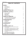
1
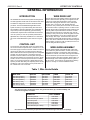
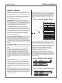
™
Automation
! IMP OR T ANT !
- F or Y our S afety R ead this manual before
ins talling or us ing this equipment
ARC PRODUCTS AUTOMATION
DWF-4 TIG WIRE FEED SYSTEM
OPERATIONS AND SERVICE MANUAL
1245 30th Street
San Diego, CA 92154-34777
619-628-1022
619-628-1028 FAX
[email protected]
service@ arc-products.com
www.ap-automation.com
www.arc-products.com
THANK YOU!!!
. . . for purchasing Arc Products Equipment. Our commitment to you is to
provide an ever expanding family of quality arc positioning equipment,
controller and accessories. Please take a moment to read the following
pages as they contain important information regarding proper use of this
product and of welding/cutting safety and procedures.
WHOM DO I CONTACT
For help?
• Contact your distributor
For additional information,
such as Technical Manuals,
Service, and Parts, Circuit
and Wire Diagrams, User’s
Guides, Distributor Directories
• Contact your distributor
To file a claim for loss or How to contact Arc
damage during shipment? Products:
• Contact your delivering carrier.
For assistance in filing or settling
claims,
• contact your distributor and/or
equipment manufacturer’s
Transportation Department
Call: 619-628-1022
Fax: 619-628-1028
[email protected]
[email protected]
Arc Products
Attn: Customer Service
1245 30th Street
San Diego, CA 92154
0600-0312 Rev. A
4
0600-0312 Rev. A
TABLE OF CONTENTS
SAFETY
DEFINITIONS
SAFETY INFORMATION
ELECTRIC SHOCK
PERSONAL PROTECTION
FIRE SAFETY
VENTILATION
SAFETY REFERENCES
7
7
7
8
8
9
9
INTRODUCTION
10
EFFECT OF CONTROLS
AMPLITUDE CONTROL
POSITION CONTROL
SPEED CONTROL
DWELL CONTROL
CALIBRATION CONTROL
11
11
11
11
12
13
EXPLANATION OF FUNCTIONS – CIRCUIT DIAGRAM
AP AUTOMATION PROBE CURRENT WAVEFORMS
TYPICAL DWELL AND FREQUENCY WAVEFORMS
PROBE-TO-TORCH MOUNTING ORIENTATION
14
15
16
17
TROUBLESHOOTING
TOOLS REQUIRED
INITIAL SET UP
TROUBLESHOOTING CHART
18
18
18
19
GENERAL INFORMATION
EFFECTS OF CONTROLS
THEORY OF OPERATION
TROUBLESHOOTING
SPECIFICATIONS
CONTROL UNIT
PROBES
PROBE TIPS
20
20
21
DRAWING & PARTS LIST
Parts List & Diagram for Arc Osc. Cont. Assembly MA-20, 0600-0211
Control Block Diagram
Parts List & Diagram for PCB Assembly, Control Circuit, 1022-0084
Parts List & Diagram for Power Supply Assembly Arc Osc., 1026-0086
Parts List & Diagram for PCB Assembly, Power Supply, 1022-0025
Parts List & Diagram for PCB Assembly, Power Amp, 1022-0122
Parts List & Diagram for Mother Board Assembly, Arc Osc., 1022-0009
Power Supply Assembly Schematic
Circuit Diagram
Parts List & Diagram for MP-1 Probe Assembly
Parts List & Diagram for MP-2 Probe Assembly
Parts List & Diagram for MP-100 Probe Assembly
General Terms & Conditions
22
24
25
27
28
29
30
31
32
33
34
35
36
5
SAFETY
6
0600-0312 Rev. A
0600-0312 Rev. A
SAFETY
SAFETY
!IMPORTANT!
THIS MANUAL HAS BEEN DESIGNED FOR
EXPERIENCED WELDING AND CUTTING EQUIPMENT
OPERATORS AND MUST BE READ COMPLETELY
BEFORE USING THIS EQUIPMENT. IF YOU LACK
EXPERIENCE OR ARE UNFAMILIAR WITH THE
PRACTICES AND SAFE OPERATION OF WELDING
AND CUTTING EQUIPMENT, PLEASE CONSULT YOUR
FOREMAN. DO NOT ATTEMPT TO INSTALL, OPERATE,
OR PERFORM MAINTENANCE ON THIS EQUIPMENT
UNLESS YOU ARE QUALIFIED AND HAVE READ AND
UNDERSTOOD THIS MANUAL. IF IN DOUBT ABOUT
INSTALLING OR OPERATING THIS EQUIPMENT,
CONTACT YOUR DISTRIBUTOR OR THE CUSTOMER
SERVICE DEPARTMENT OF Arc Products.
DEFINITIONS
Throughout this manual, NOTE, CAUTION, WARNING
and DANGER are inserted to call attention to particular
information. The methods used to identify these
highlights and the purpose for which each is used, are
as follows:
SAFETY
INFORMATION
Safety is a combination of good judgement and proper
training. Operation and maintenance of any arc
welding and cutting equipment involves potential
hazards. Individuals who are unfamiliar with cutting
and welding equipment, use faulty judgement or lack
proper training, may cause injury to themselves and
others. Personnel should be alerted to the following
potential hazards and the safeguards necessary to
avoid possible injury. In addition, before operating this
equipment, you should be aware of your employer’s
safety regulations.
BE SURE TO READ AND FOLLOW ALL AVAILABLE
SAFETY REGULATIONS BEFORE USING THIS
EQUIPMENT.
ELECTRIC SHOCK
NOTE
Operational, procedural, and background information
which aids the operator in the use of the machine,
helps the service personnel in the performance of
maintenance, and prevents damage to the equipment.
CAUTION
An operational procedure which, if not followed, may
cause minor injury to the operator, service personnel
and/or bystanders.
WARNING
An operational procedure which, if not followed, may
cause severe injury to the operator, service personnel,
or others in the operating area.
DANGER
THE VOLTAGES PRESENT IN THE WELDING AND
CUTTING ENVIRONMENT CAN CAUSE SEVERE
BURNS TO THE BODY OR FATAL SHOCK. THE
SEVERITY OF ELECTRICAL SHOCK IS DETERMINED
BY THE PATH AND THE AMOUNT OF CURRENT
THROUGH THE BODY.
A) Install and continue to maintain equipment
according to USA Standard C1, National Electric Code.
B) Never allow live metal parts to touch bare skin or
any wet clothing. Use only dry gloves.
C) When welding or cutting in a damp area, or when
standing on metal, make sure you are well insulated by
wearing dry gloves, rubber soled shoes, and by
standing on a dry board or platform.
D) Do not use worn or damaged welding or torch
cables. Do not overload the cables. Use well
maintained equipment.
An operational procedure which, if not followed, will
cause severe injury or even death to the operator,
service personnel or bystanders.
E) When not welding/cutting, turn equipment OFF.
Accidental grounding can cause overheating and
create a fire hazard. Do not coil or loop the cable
around parts of the body.
7
SAFETY
0600-0312 Rev. A
F) The ground cable should be connected to the
workpiece as close to the work area as possible.
Grounds connected to building framework or other
locations remote to the work area reduce efficiency
and increase the potential hazard of electric shock.
Avoid the possibility of the cutting current passing
through lifting chains, crane cables or other electrical
paths.
G) Keep everything dry you might touch, including
clothing, the work area, welding gun, torch and
welding or cutting machines. Fix water leaks
immediately. Do not operate equipment standing in
water.
H) Never use a cutting torch or welding gun which is
damaged or contains cracks in its housing.
D) Always wear safety glasses or goggles when in a
cutting or welding area. Use safety glasses with side
shields or goggles when chipping slag or grinding.
Chipped slag is hot and may travel a considerable
distance. Bystanders should also wear safety glasses
or goggles.
E) Compressed gas cylinders are potentially
dangerous, refer to the suppliers for proper handling
procedures.
F) Wear ear plugs or other ear protection devices when
operating cutting or welding equipment.
FIRE SAFETY
I) Refer to AWS-Z49.1 for grounding
recommendations.
PERSONAL
PROTECTION
SKIN AND EYE BURNS RESULTING FROM BODY
EXPOSURE TO ELECTRIC-ARC WELDING AND
CUTTING RAYS OR HOT METAL CAN BE MORE
SEVERE THAN SUNBURN.
A) Use a proper face shield fitted with the correct filter
(#10 or greater) and cover plates to protect your eyes,
face, neck and ears from the sparks and rays of the
cutting/welding arc when cutting/welding or observing
cutting/welding. Warn bystanders not to watch the arc
and not to expose themselves to the cutting/welding
arc rays or to hot metal.
B) Wear flameproof gauntlet-type gloves, a heavy longsleeve shirt, cuff-less trousers, high-topped shoes, and
a welding helmet or cap (for hair protection) to protect
the skin from arc rays and hot sparks or hot metal.
C) Protect other nearby personnel from arc rays and
hot sparks with a suitable nonflammable partition.
8
HOT SLAG OR SPARKS CAN CAUSE A SERIOUS FIRE
WHEN IN CONTACT WITH COMBUSTIBLE SOLIDS,
LIQUIDS OR GASES.
A) Move all combustible materials well away from the
cutting area or completely cover materials with a
nonflammable covering. Combustible materials include
but are not limited to wood, clothing, sawdust,
gasoline, kerosene, paints, solvents, natural gases,
acetylene, propane, and similar articles.
B) Do not weld, cut or perform other hot work on used
barrels, drums, tanks or other containers until they
have been completely cleaned. There must be no
substances in the container which might produce
flammable or toxic vapors.
C) For fire protection, have suitable extinguishing
equipment handy for instant use.
0600-0312 Rev. A
VENTILATION
SAFETY
NEMA Standard EW1-2.02 approved as ANSI C87.1-1976
outlines both usual and unusual service conditions for a
welding power source. AP Automation products have been
designed and manufactured to meet the usual service
conditions as well as conform to the other NEMA standards. If
an unusual service condition is required, Arc Products/AP
Automation should be consulted.
WELDING AND CUTTING FUMES AND GASES,
PARTICULARLY IN CONFINED SPACES, CAN CAUSE
DISCOMFORT AND PHYSICAL HARM IF INHALED
OVER AN EXTENDED PERIOD OF TIME.
A) INSTALLATION
Install the equipment in accordance with OSHA and National
Electrical Code Standards, or other applicable standards.
A) At all times, provide adequate ventilation in the
welding and cutting area by either natural or
mechanical means. Do not weld or cut on galvanized,
zinc, lead, beryllium or cadmium materials unless
positive mechanical ventilation is provided to prevent
inhaling fumes and gases from these materials.
B) COOLING
Locate the AP Automation Welding equipment so that airflow
into the front and out of the back is not obstructed. Avoid
placing the unit where dust or grinding particles will be
directed into the unit.
B) Do not weld or cut in locations close to chlorinated
hydrocarbon vapors coming from de-greasing or
spraying operations. The heat of arc rays can react
with solvent vapors to form phosgene, a highly toxic
gas, and other irritant gases.
C) ACCESS
Locate the AP Automation equipment where there is room for
the operator to manipulate the controls or change the
connections on either the front or the rear. Avoid placing
the unit in a hallway or other area where foot traffic might
be impeded.
C) If you develop momentary eye, nose or throat
irritation during welding or cutting, it is an indication
that the ventilation is not adequate. Stop work and take
the necessary steps to improve ventilation in the
welding or cutting area. Do not continue to weld or cut
if physical discomfort persists.
D) SECURITY
Locate the unit where it can be secured to a platform, deck or
other structure that is capable of safely supporting the
unit and any other potential load.
D) Use an air supplied respirator if ventilation is not
adequate to remove all fumes and gases.
E) Beware of gas leaks. Welding or cutting gases
containing argon are more dense than air and will
replace air when used in confined spaces. Do not
locate gas cylinders in confined spaces. When not in
use, shut OFF the gas supply at its source.
F) Refer to AWS Standard Z49.1 for specific ventilation
recommendations.
LOCATION OF EQUIPMENT
(Service Operating Conditions)
WARNING THE SMALL SIZE AND UNIQUE
DESIGN OF AP AUTOMATION’S PRODUCT LINE
REQUIRES THE OPERATOR BE AWARE OF CERTAIN
SAFEGUARDS REGARDING THE PROPER PROCEDURE FOR PLACEMENT OF THE EQUIPMENT.
GOOD JUDGMENT AND COMPLIANCE WITH YOUR
PARTICULAR JOB SITE SAFETY REQUIREMENTS
ARE ESSENTIAL. THE FOLLOWING SAFEGUARDS
ARE RECOMMENDED.
PORTABILITY
WARNING
THE SMALL SIZE AND UNIQUE DESIGN
OF AP AUTOMATION’S PRODUCT LINE REQUIRE THAT
THE OPERATOR BE AWARE OF CERTAIN SAFEGUARDS
CONCERNING THE MOVEMENT OF THE EQUIPMENT.
GOOD JUDGMENT AND COMPLIANCE WITH YOUR
PARTICULAR JOB SITE SAFETY REQUIREMENTS ARE
ESSENTIAL THE FOLLOWING SAFEGUARDS ARE
RECOMMENDED:
A) In lifting and carrying a power source it is recommended
that two people be used. The unit is designed to be lifted
using a suitably rated and inspected choker (made of
rope or nylon) run through both handles. Refer to the
applicable OSHA standards or contact AP Automation for
any questions regarding the lifting of this unit. Accessory
units of less than 25 Ibs. may be safely lifted by one
individual.
B) Never drag, pull or lift the unit by the cables. Always lift
the unit using the handles provided.
C) Never move the unit to a position that would allow its
input and output cables to impede or block foot traffic.
9
SAFETY
D) Move and lift the unit in accordance with OSHA job
site standards.
E) Do not allow the unit to remain operating when lifting
or moving it.
F)
Never move a power source unless all 10 flange
screws and nuts holding the top and bottom cases
are tight.
G) Do not lift a power source/wire feeder combination
when the wire feeder is mounted to the power
source handles. Always disassemble the wire feeder
from the power source before lifting.
DANGER
ANY TIME AP AUTOMATION EQUIPMENT IS PLACED ABOVE GROUND LEVEL, THE
POTENTIAL HAZARD OF THE UNIT FALLING EXISTS.
SAFETY PRECAUTlONS
AROUND ARC
POSITIONING SYSTEMS
AP Automation equipment employs the use of moving
electromechanical components to position the weld head
and torch. Operators should exercise caution when working
with moving equipment. Care should be taken not to allow
loose clothing, jewelry or hair to get caught in the equipment
causing injury. All automated systems should be turned off
and have AC power positively disconnected before maintenance or repair.
10
0600-0312 Rev. A
SAFETY REFERENCES
The following publications provide additional
information on important welding safeguards.
A) ANSI/ASC Z49.1-1988, American National Standard
“Safety in Welding and Cutting”.
B) Bulletin No. F4-1, “Recommended Safe Practices for
the Preparation for Welding and Cutting Containers
and Piping that have held Hazardous Substances”.
C) OSHA Safety and Health Standards, 29CFR 1910,
available from the United States Department of Labor,
Washington, DC 20210.
D) NFPA Standard 518, “Fire Prevention in Use of
Cutting and Welding Processes”, available from the
National Fire Protection Association, 470 Atlantic
Avenue, Boston, MA 0021 0.
E) NEMA Standards Publication/No. EW1-1989, Electric
Arc-Welding Apparatus, approved as ANSI C87.1-1989.
Available from National Electrical Manufacturers
Association, 155 E. 44th Street, New York, NY 10017.
0600-0312 Rev. A
EFFECTS OF CONTROLS
GENERAL INFORMATION
INTRODUCTION
WIRE DRIVE UNIT
AP AUTOMATION cold wire feed systems are designed for
accurate application of filler wire into the weld or braze area.
The DWF-4 is designed to be used for GTAW and PAW
processes. The AP AUTOMATION Digital Wire Feeder
System is made up of a positive feeding wire drive with a
zero backlash 3-axis wire manipulator. This combination of
components produces exceptionally good wire feeding
characteristics. Systems will accommodate wire sizes from
.020" dia. (.50mm) to .094" dia. (2.39mm) and feed at an
adjustable rate, continuously variable from 0 to 300 inches
per minute. A standard DWF-4 system is shown in Figure
1.1.
The wire drive unit uses urethane rollers to grip the wire and
feed it in either direction depending on the signals from the
control unit. These rollers eliminate the need to change
rollers when changing wire sizes from .020" (.50mm) dia.
through .062" (1.57 mm) dia. wire. Special rollers are
required for .094 (2.39mm) dia. wire. All wire can be loaded
into the drive while it is operating. There is no need to handfeed the wire through the mechanism before operating. Inlet
and exit guides are provided with the wire drive. one inlet
guide covers the entire range of wire sizes from .020" dia.
(.50mm) to .094" (2.39 mm) dia. Three exit guides cover the
range of wire diameters. Two of the exit guides are for the
.020" through .062" range. The third is for the .094" wire.
The guides are stored inside the drive housing. If a drive for
.020" -.062" wire is ordered then two exit and one inlet guide
will be supplied. If a drive for .094" is ordered, then one exit
and one inlet guide will be supplied.
CONTROL UNIT
The control unit uses solid state circuitry in its motor supply
and control circuits and operates from a 115/230 V.A.C., 50/
60 Hz line supply. Provisions have been made for forward or
reverse jog to allow easy pre-positioning of the filler wire.
Start of wire feed and control of speed may be accomplished
manually, from the front panel, or remotely, through the
interface connector located on the rear panel. The speed at
which the wire will feed is pre-set through use of the “PUSH
TO SET” function on the front panel and can be controlled
within .10" per minute increments. A digital readout of wire
speed is provided. Start delay and stop delay timers are also
provided for cycle control. Timers can be pre-set within .10
sec. intervals from 0 to 9.9 seconds.
WIRE GUIDE ASSEMBLY
The wire guide assembly used with the DWF-4 wire drive
unit consists of a guide mechanism, conduit, liners, and tip.
The guide mechanism is constructed to allow full position
adjustment for vertical, cross seam, feed angle and distance
from the electrode. Tips and liners can be changed to suit
the wire size being used (see information listed in Table 1.1)
Standard length of the conduit supplied with the system is
36" (914.4mm). The length may be shortened by following
steps 2.5.1 through 2.5.4 in the installation section.
Table 1, Wire Guide Details
WIRE SIZE
ROLLER
EXIT GUIDE
LINER
GUIDE TIP
.020" DIA (0.50mm)
.030" DIA (0.76mm)
.035" DIA (0.89mm)
.045" DIA (1.1mm)
.062" DIA (1. 5mm)
.094" DIA (2. 39mm)
1066-0084
1066-0084
1066-0084
1066-0084
1066-0084
1066-0092
1070-0051
1070-0051
1070-0051
1070-0051
1070-0086
1070-0116
2360-0951
2360-0951
2360-0951
2360-0951
2360-0960
NONE
1076-0038
2360-0137
2360-0137
2360-0145
2360-0153
2360-0099
You may also order a combination of the wire guide mechanism, tip, conduit assembly, and
conduit liner together, as follows:
WIRE SIZE
.020" DIA (.50mml
.030-.035" DIA (.76-.89mml
.045" DIA (l.lmml
.062" DIA (1.5mml
.094" DIA (2.39mml
.020-.062" DIA (.50-1.5mm)
PART NUMBER
1060-0022
1060-0031
1060-0049
1060-0057
1060-0065
1060-0171*
*This includes all tips necessary for operation from .020" DIA through .062" DIA in one package.
11
GENERAL INFORMATION
0600-0312 Rev. A
INSTALLATION
GENERAL SET-UP
A standard AP Automation DWF-4 system is illustrated in Figure 2.1 with the necessary interconnections shown for a typical
installation. The parts are listed below:
Table 2, DWF-4 Components
DWF-4 (.020-.062)
DWF-4 (.094")
Control Unit
0600-0217
0600-0217
Wire Drive Unit
1060-0006
1060-0014
Wire Guide Assembly
1060-0171
1060-0189
CONTROL UNIT LOCATION
The control unit should be placed in a location that provides
easy access to the controls and proper air ventilation for
cooling. Adequate ventilation is provided by maintaining a
minimum of 5" (127mm) of unrestricted space between the
control unit sides and rear and the nearest obstruction. The
location should be selected to minimize any dust, dirt,
moisture or corrosive vapors the control unit could be
subjected to. Control unit outline dimensions are given in
Figure 2.2.
12
CAUTION
THE CONTROL UNIT CAN OPERATE
ON EITHER 100/120 VOLTS OR 208/230 VOLTS AC, 50
OR 60 HZ. BE SURE TO SELECT THE PROPER INPUT
VOLTAGE ON THE REAR PANEL BEFORE CONNECTING
TO POWER.
0600-0312 Rev. A
EFFECTS OF CONTROLS
13
GENERAL INFORMATION
0600-0312 Rev. A
WIRE DRIVE UNIT MOUNTING
Figure 4 is an outline and a mounting dimension guide. The drive unit may be mounted using the inlet guide surface or the
bottom surface (opposite the adjusting knob) through use of the existing tapped holes in the housing. The wire drive exit
guide has a 7/16- 20 UNF external thread for mating with the supplied wire guide conduit for a DWF-4 system.
¼" -20 unc
x .31" DP
2 Mounting Holes
4.0"
4.69"
4.31"
Side
4.65"
Wire
Feed
2.45"
2.875"
Ctrs
5.53"
.62"
1.750"
Ctrs
2 Bottom Mounting Holes
.78"
1.65"
1.12"
Wire Drive Unit
1-3/8" Dia.
Barrel
Torch
¼" -20 unc
x .31" DP
2 Bottom
Mounting
Holes
3.75"
Torch
8.25"
Approx.
Wire Guide Manipulator
Figure 4, Wire Drive Unit and Wire Guide Manipulator Dimensions
14
0600-0312 Rev. A
EFFECTS OF CONTROLS
CAUTION
IN APPLICATIONS WHERE HIGH FREQUENCY OR CAPACITIVE DISCHARGE START IS USED THE
DRIVE HOUSING SHOULD BE GROUNDED TO THE SAME POTENTIAL AS THE WORKPIECE. THIS WILL PREVENT
POSSIBLE DAMAGE TO THE WIRE FEED DRIVE.CAUSED BY ARCING. GROUNDING CAN BE ACCOMPLISHED
THROUGH THE UNUSED THREADED MOUNTING HOLES IN THE DRIVE HOUSING.
SOCKET
SLEEVE
NIPPLE
FITTING COMPONENTS
WIRE GUIDE MOUNTING
a sharp cut-off wheel or a fine-tooth hack saw. Remove
tape and trim any loose wires flush with tube stock. Any
burrs on the bore of the tube stock should be removed
with a knife. Clean the hose bore. The wire braid will
tend to “neck down” on this end. This is characteristic of
wire braid hose and can be used to advantage in the
assembly of the fittings. Slip the socket over the
“necked down “ end of the hose, positioned approximately 3” (76 mm) from the end. Mount nipple hex in a
The guide mechanism portion of the wire guide assembly is
made to accommodate a standard 1-3/8" (34.9mml diameter
machine torch barrel (see Figure 2.4). Guide tips are
available for specific wire sizes from .020" to .094" in
diameter. The conduit, with proper liner, is attached to both
the wire drive exit guide and the wire guide mechanism (see
Table 1.1 for proper selection of these parts). Sharp bends
in the conduit must be avoided. If shorter conduit lengths
are required, see Section 2.51.
CONDUIT LENGTH ADJUSTMENT
The conduit as supplied is an assembled unit 36" (914 mm)
in length. If shorter lengths are desired, the conduit may be
cut and reassembled according to the following steps.
A)
Disassemble existing fitting on one end. Save the fitting
components. Wrap hose with masking tape at cut-off
point and cut square to length through taped area using
vise. Work the hose bore over the nipple to size the
tube and aid in separating the braid prior to fitting the
sleeve. Remove hose from nipple.
B)
Push the sleeve over the end of the tube and under the
wire braid by hand. Complete positioning of the sleeve
by pushing the hose end against a flat surface. Visually
inspect to see that tube stock butts against the inside
shoulder of the sleeve. Set the sleeve barbs into the
Teflon tube by pushing the assembly tool or a round
nose tapered punch into the end of the sleeve and tube.
15
THEORY OF OPERATION
0600-0312 Rev. A
Table 4, Wire Guide Assembly Parts list
SIGNAL
Remote Start/Stop
Inhibit
FWD/REV JOG
Remote Speed Control
Start Delay On
Auto Feed
Motor Pulse
C)
D)
REMARKS
5-24 VDC, or contact closure signal to start
5-24 VDC, or contact closure signal to inhibit wire
feed without stopping weld cycle
Contact closure signal to drive wire forward or
reverse
10K potentiometer or 0-1.235 volt signal for 0-300
ipm
24 VDC lamp, or relay drive during start delay
24 VDC lamp, or relay drive during automatic cycle
wire feed
24 VDC low level signal pulse 1 pulse .0116 inches
of wire travel.
Lubricate nipple and socket threads. For stainless steel
fittings, use a molydisulfide base lubricant (e.g.
.Molykote Type G) ; lubricants containing chloride are
not recommended. Other material combinations use
standard petroleum lubricants. Hold the nipple with hex
in vise. Push hose over nipple with twisting motion until
seated against nipple chamfer. Push socket forward,
and hand start threading of socket to nipple.
Wrench-tighten nipple hex until clearance with socket
hex is 1/32" or less. Tighten further to align corners of
nipple and socket hexes. Clean and inspect all
assemblies.
After the conduit is prepared, the liner may be cut to
length and installed as shown in Figure 2.4 and
explained in Section 2.4.
REMOTE CONTROLS
A number of remote capabilities are available with the DWF4 system. On the rear panel of the control unit a connector is
provided for remote operation. Optional remote controls are
available such as the Remote Control Pendant, and Wire
Feed Pulse Cycle Control. They have their own separate
housings with cable and connector for mating directly to the
control unit remote connector. See Section 6 for details.
The remote connector, in addition to providing for the
remote control connections, provides the user access to
other wire feeder signals. This may be used to incorporate
the DWF-4 into a complete welding package system. The
signals available are listed in Figure 3.3 and are described
in more detail in Section 3.4. AP Automation also provides
an optional pre-wired connector and shielded cable for
connection to these signals. (See Sections 3.4 and 6.1).
CHANGING RETRACT DISTANCE
The wire retract distance which occurs at the end of a wire
feed cycle comes preset from the factory at .512 inches.
This distance can be changed through the range of .085
inches to 1.28 inches by changing the “E” jumpers. (See
Table 4.4) .
16
0600-0312 Rev. A
THEORY OF OPERATION
OPERATION
PRECAUTIONS
Verify the following before connecting power to control unit.
A)
Make certain the drive unit is grounded.
B)
Check that all connections are secure and properly
installed. All connections should be made to the torch
and power supply before applying power to the control
unit.
C)
Should the cover of the control unit be removed for any
reason, be sure the AC line cord is disconnected.
D)
Check line voltage selector switch on rear panel for
proper input voltage being used.
CAUTION
THE CONTROL UNIT CAN OPERATE
ON EITHER 100/120 VOLTS OR 208/230 VOLTS AC, 50
OR 60 HZ. BE SURE TO SELECT THE PROPER INPUT
VOLTAGE ON THE REAR PANEL BEFORE CONNECTING
CONTROL DESCRIPTION -DWF-4
Refer to Figure 6 for location of the following front panel
controls.
ON-OFF: Switches primary line voltage to the control unit.
When power is ON, the power indicator will be illuminated.
MANUAL START - OFF - REMOTE START: In the center
OFF position, a wire feed cannot be initiated; in the up
MANUAL START position, a wire feed cycle is started. If this
switch is placed down, in the REMOTE START position, a
wire feed cycle can be initiated by applying an external
signal to the proper pins of the remote connector on the rear
panel. (See page ??? for complete details on REMOTE
START.) The feed cycle stops for the DWF-4 system when
either the REMOTE START (if used) or the MANUAL
START switch is placed in the OFF position.
REVERSE -FORWARD JOG: Pressing the Jog Switch
down, to the FORWARD position, will cause wire to feed out
of the wire drive unit at the rate of 102.4 inches per min;
(2601 mm/min) this speed is factory set and cannot be
changed. Pressing the Jog Switch up, to the REVERSE
position, will cause wire to be pulled back into the wire drive
unit -also at 102.4 inches per min. (2601 mm/min). Releasing the switch will cause it to return to the center OFF
position. In this way wire can be pre-positioned for the weld
cycle.
START DELAY: Allows for a delay between the time a weld
cycle is initiated and the time when wire feeding begins;
START DELAY is preset table in .1 second increments, from
0.0 to 9.9 seconds.
then stops feeding. STOP DELAY allows for crater fill and is
variable from 0 to 9.9 seconds in .1 sec. intervals.
WIRE SPEED: Digital display that indicates WIRE SPEED
in inches per minute, in .1 inch per minute increments.
PUSH TO SET: Used in conjunction with the SPEED control
to preset wire feed rate. Pressing this switch while rotating
the speed control allows the operator to preset the wire feed
rate without actually feeding wire, thereby eliminating waste
of filler wire.
SPEED CONTROL: When in the STANDARD position, wire
speed is controlled by the SPEED potentiometer located
directly under the digital display on the control panel. When
in the REMOTE position, wire speed is controlled by a
REMOTE signal.
SEQUENCE OF OPERATION
After the DWF-4 has been installed, make sure all cables
and connectors are properly mated. Check the line voltage
selector switch on the rear panel to ensure it is set at the
proper position to match the line voltage being used. The
MANUAL/REMOTE switch should be in the OFF position.
Back off thumbscrew on the drive unit to allow introduction
of wire between drive rolls. Turn the power switch ON. The
POWER indicator should illuminate and the digital display
should read all zeros. Adjust thumbscrew to provide contact
on wire. Activate the FORWARD Jog Switch and “guide” the
filler wire into the wire drive entrance guide. The rollers will
“pick up” the wire and begin feeding. Continue feeding the
wire FORWARD until the wire is in position at the end of the
guide tip. Use JOG FORWARD/REVERSE to adjust
position.
Select the desired amount of START DELAY by setting the
thumb-wheel switches to the appropriate value. Do the
same for STOP DELAY or FEED TIME as applicable. Next,
select the WIRE SPEED by pressing the PUSH TO SET
button. While holding this button in, rotate the SPEED knob
until the desired WIRE SPEED is indicated on the digital
display; set the SPEED CONTROL selector switch to the
STANDARD position. Positioning the MANUAL START/
REMOTE START switch to the MANUAL START position
will now initiate a wire feed cycle.
The digital display will blink during START DELAY time. At
the end of START DELAY, wire will begin to feed and the
speed will be indicated on the display. Re-setting the
MANUAL START switch to OFF will initiate the end of a wire
feed cycle for the DWF-4. After STOP DELAY times out, the
motor on the wire drive unit will reverse and retract the filler
wire from the weld puddle; after the retract time, wire will
stop feeding and the cycle is complete.
STOP DELAY: Allows for a delay between the time when a
weld cycle is terminated and the time when wire retracts
17
THEORY OF OPERATION
0600-0312 Rev. A
Figure 6, DWF-4 Rear Panel
18
0600-0312 Rev. A
THEORY OF OPERATION
REMOTE SIGNALS
Electrical connections are made as shown in Figures 7, 8,
and 9. A pre-wired connector and cable is available from
AP Automation (P/N 1074-0045).
REMOTE START is implemented by applying a signal
between PIN C and F. PIN C is the positive terminal and PIN
F is the negative terminal. This signal should be 5-24 VDC.
The cycle will remain active as long as the signal is applied.
The cycle terminates when the signal is removed.
MOTOR PULSE signal is an output that signals each step of
the feed motor. This signal is a 24V, 18-sec wide pulse with
a 10K source resistance. It may be used for a tachometer
output of wire length output. Each pulse represents .0116
inches of wire feed. The signal is on PIN H; return is ground
(PIN D).
Figure 7, REMOTE WIRING CABLE
Pins
{
The DWF-4 control unit has the capability of being controlled from a remote location. Seven signals are available
as described in Table 4 as well as the following paragraphs.
I
J
H
The INHIBIT FUNCTION is implemented by applying a
signal to PINS E and G; PIN E is positive and PIN G is
negative. This signal should be 5-24 VDC. When the inhibit
signal is applied, the wire feed is interrupted, but the cycle is
not affected at its point in the cycle. When the inhibit signal
is removed, the wire feed will continue. This feature is
helpful for manual override or a pulse synchronization of
wire to a pulsing power source.
REMOTE JOG FORWARD/REVERSE is implemented by
the use of a SPDT switch. The center pole is connected to
PIN D. The forward pole is connected to PIN D. The
forward pole is connected to PIN L, and the reverse pole is
connected to PIN K. This switch is now wired in parallel with
the Jog switch on the front panel, and functions in the same
manner.
REMOTE WIRE SPEED control is implemented in much the
same way. A 10K 1/2W potentiometer is connected with its
wiper
(center pole) on PIN N. The plus reference voltage pole is
connected to PIN M and the minus or ground pole is
connected to PIN A. This pot is now selected by switching
the speed control switch on the front panel (lower right
corner of wire speed area) to the REMOTE position. Wire
speed is now determined by setting this pot. The wire speed
may also be controlled by a 0 to 1.235 volt signal (PIN A to
PIN N which corresponds to O to 300 inch per minute wire
speed).
BROWN
START DELAY
BLACK
NO CONNECTION
RED
AUTO FEED
BLACK
NO CONNECTION
ORANGE MOTOR PULSES
BLACK
NO CONNECTION
B
YELLOW +20 VOLTS
D
BLACK
DIGITAL GROUND
A
BLACK
ANALOG GND
N
GREEN
WIPER
M
BLUE
POT (REF)
BLACK
NO CONNECTION
E
WHITE
INHIBIT (+)
G
BLACK
INHIBIT (-)
C
RED
START (+)
F
WHITE
START (-)
L
RED
FORWARD
K
GREEN
REVERSE
The remote start function requires a signal of +5 to 24 VDC.
This signal is applied to PIN C of J3. The common is from
the DWF-4. This signal is optically isolated from the DWF4; therefore, the signal common need not be attached to the
control unit ground. This signal would normally come
through the normally open contacts of a relay that is
activated at the start of a weld cycle, for example, the AP
Automation Seam Tracker interface relay.
The inhibit function requires a signal of +5 to 24 VDC
applied to PIN E of J3, and common connected to PIN G of
J3. The inhibit signals are optically isolated from the DWF-4
control unit, and the common need not be connected to the
control unit ground.
Figure 8, REMOTE START WIRING
REMOTE START DELAY signal is an output that signals
when the system is in the DELAY timing mode. When the
START DELAY times out, the signal is removed. This signal
is 24 VDC 500mA max current. It may be used to light a
remote indicator lamp or energize a relay coil. The signal
connects to PIN I of the remote connector; return is ground
(PIN D).
REMOTE AUTO FEED signal is an output that signals when
the system is feeding wire automatically at the selected rate.
Its output characteristics are the same as the remote start
delay signal. The signal is on PIN J at the remote connector;
return is ground (PIN D).
PIN B
PIN C
PIN F
PIN D
+20 VDC
REMOTE START (+)
REMOTE START (-)
GROUND
Figure 9, INHIBIT FUNCTION WIRING
PIN B
PIN E
PIN G
PIN D
+20 VDC
INHIBIT (+)
INHIBIT (-)
GROUND
19
TROUBLESHOOTING
0600-0312 Rev. A
MAINTENANCE AND REPAIR
MAINTENANCE REQUIREMENTS
CONTROL UNIT CALIBRATION
The DWF-4 wire feed system has no special scheduled
maintenance requirements. However, periodic inspection of
control and wire drive is helpful in preventing equipment
failures. Replace any worn or broken parts found. Periodic
dust and oil removal from both the control and drive is
recommended.
The control unit has been calibrated and fully tested before
leaving the factory. It is unlikely that it would require
adjustment, however, if the need for re-calibration arises,
there are three adjustments that can be made that affect
wire speed and delay time accuracy. The only test equipment required is a good quality frequency counter of known
accuracy. Refer to Figure 11 for easy location of the
potentiometers and test points. Two adjustments, R2 and R7
affect wire speed accuracy. Perform the following steps to
calibrate the control unit.
GENERAL PRECAUTIONS
Figure 10 shows a control unit for the DWF-4 system.
Assemblies and parts that are authorized for user replacement are listed in Table 6. Should the user experience a
problem and determine the defective part (see TROUBLESHOOTING, Table 5), the suggested repair procedure is to
remove and replace the defective part. Figure 11 and Table
7 provide a detailed parts breakdown of the circuit board
assembly.
CAUTION WHEN INSPECTING OR REPAIRING
A)
Connect the frequency counter to TP 14.
B)
Rotate the speed control knob on the front panel to its
minimum speed setting, i.e. fully counter-clockwise.
Now adjust R7 until the frequency counter indicates
zero.
C)
Repeat Step B). There is only one adjustment to be
made on the time base osc. -R10; it sets the start and
stop delay accuracy and the wire speed readout
accuracy.
D)
Connect the frequency counter to TP 2, and adjust R10
for a reading of 2560 Hz ± 1 Hz.
THE CONTROL UNIT ASSEMBLY, DISCONNECT AC
POWER FROM THE UNIT BEFORE REMOVING THE
COVER TO PREVENT ELECTRICAL SHOCK.
NOTE
REPEAT STEPS B) THROUGH D) IF THE ADJUSTMENT
ON R10 IS CHANGED.
20
0600-0312 Rev. A
TROUBLESHOOTING
TROUBLESHOOTING CHART
Table 5, Troubleshooting Guide
TROUBLE INDICATION
1 Power ON lamp does not
REPAIR STEPS
a Verify that power cord is plugged in and circuit breaker is reset.
light.
b Verify that all plugs are installed in the circuit board.
c Check +20v (TP 9, Figure 11). Replace board if necessary.
d Check lamp; replace if necessary.
2 Digital display does not
a Repeat Steps a, b and c above.
light.
b Check +5v (TP 12, Figure 11). Replace board if necessary.
c Replace digital display board
3 Incorrect START/STOP
a Repeat Step 1-b above.
delays
b Recalibrate (see Section "Control Unit Calibration").
c Replace thumbwheel assembly or circuit board.
4 Feed cycle does not start
a Verify that MANUAL START/OFF/REMOTE switch is in correct
position.
b Repeat Step 1-b above
c Replace circuit board.
5 Incorrect wire feed speed
a Verify that SPEED CONTROL switch is in correct position.
b Repeat Step 1-b and 3-b above.
c Check input signal (TP 15, Figure 11). Replace speed pot or circuit
board if necessary.
d Verify that thumbscrew is fully seated. Exception: Back off one full turn
when using .020" dia. wire.
e Verify that correct drive rolls for wire diameter are installed (see
Table 1).
f Check roller surface; if excessively worn, slip off urethane wheels and
replace.
6 Motor turns but wire does
a Verify that drive unit is connected to control.
not feed.
b Repeat Step 1-b above.
c Check motor and cable continuity. It should be about 1.5 ohms from
PIN A, D, E and C referenced to pin B on motor connector. Repair or
replace if necessary.
d Check motor current (speed less than 10 ipm = 80-110 mv between
TP 7 and TP 8 - see Figure 11). Replace circuit board if necessary.
e Loosen feed tension adjustment knob completely. Verify wire runs
smoothly off wire reel and through guides and conduit.
f Verify thumbscrew is properly adjusted. Exception: Back off one full
turn when using .020" dia. wire.
g Verify correct drive rolls for wire diameter. (See Table 1) .
h Check roller surface; if excessively worn, slip off urethane wheels and
replace.
21
DRAWING & PARTS LISTS
0600-0312 Rev. A
DRAWING & PARTS LIST
Figure 10, Control Unit Assembly, PN 0600-0217
22
0600-0312 Rev. A
DRAWING & PARTS LISTS
Table 6, Parts List for Control Unit Assembly
ITEM
QTY
PART No.
DESCRIPTION
1
1
1066-0009
CHASSIS ASSY
2
1
1062-0007
PWB DWF-4 CONTROLLER/DRIVER
3
1
1062-0015
PWB DWF-4 DISPLAY AND DRIVER
4
1
1066-0041
TRANSFORMER ASSY, DWF-4
5
1
1066-0033
ASSY, THUMBWHEEL SWITCH
6
1
1066-0025
ASSY, THUMBWHEEL SWITCH
7
1
1074-0011
CABLE ASSY,DWF-4 INTERNAL INTERFACE
8
1
1074-0029
CABLE ASSY,DWF-4 DRIVE INTERFACE
9
1
2066-0139
SWITCH, JOG FWD/REV OR 120/140 VOLT
10
1
2120-0131
CIRCUIT BREAKER ETA TYPE, 1 AMP
11
1
2060-0047
SWITCH, JOG FWD/REV
12
1
2060-0071
SWITCH, SPEED CONTROL,STAND/REMOTE
13
1
2624-0051
POT 10K,10 TURN,SPEED CONTROL
14
1
2062-0056
SWITCH, MOMENTARY, PRESS TO SET
15
1
2060-0055
SWITCH, REMOTE START/MANUAL START
16
1
2060-0063
SWITCH, POWER ON/OFF
17
1
941000-011
LAMP POWER ON INDICATOR
18
1
2120-0123
RFI FILTER AC INPUT LINE
23
DRAWING & PARTS LISTS
0600-0312 Rev. A
DWF-4
CONDUIT
A/R
A/R
Figure 5, Wire Guide Assembly
24
0600-0312 Rev. A
DRAWING & PARTS LISTS
Table 3, Wire Guide Assembly Parts list
ITEM
QTY
PART No.
DESCRIPTION
1
1
1070-1066
BODY MANIPULATOR MACHINED
2
1
1070-1074
PIVOT -WIRE MANIPULATOR
3
1
1070-1023
KNOB, VERT. ADJ -WIRE MANIP.
4
1
1070-1031
CLAMP, WIRE MANIPULATOR
5
1
1076-1035
RACK -WIRE MANIPUALATOR
6
1
1070-0167
CLAMP , TORCH
7
1
1070-1091
COUPLING, MANIPULATOR, TWECO
8
1
2408-1079
SCREW, THUMB 10-32 ST STEEL
9
1
2408-1296
SCREW, THUMB
10
2
1076-0097
FITTING MODIFIED
11
1
2380-0187
HOSE, FLEX -TEFLON LINED
12
1
2360-1567
TIP, WIRE GUIDE, .020
13
1
2360-1575
TIP, WIRE GUIDE, .035
14
1
2360-1583
TIP, WIRE GUIDE, .045
15
1
2360-1591
TIP, WIRE GUIDE, .062
16
1
2360-1605
TIP, WIRE GUIDE, .030
17
1
2360-1613
TIP, WIRE GUIDE, .052
18
1
2360-0099
TIP, WIRE GUIDE, .094
19
A/R
2360-0951
LINER, CONDUIT
20
A/R
2360-0960
LINER, CONDUIT
25
DRAWING & PARTS LISTS
0600-0312 Rev. A
Figure 10, Controller/Driver PWB Assembly, PN 1062-0007
Table 6, Parts List for Controller/Driver PWB Assembly
26
QTY
PART No.
1
1
1
2
1
1
1
1
1
4
1
1
1
1
2
3
3
1
1075-0041
1175-0044
2208-0571
2208-0563
1108-0555
2208-0385
2208-0377
2208-0580
2820-0072
2800-0251
2810-0311
2800-0375
2800-0626
2800-0227
2800-0065
2800-0359
2800-0022
2800-0014
DESCRIPTION
REF. DESIGNATION
PWB,DRILLED -CONT/DRVR
HEATSINK,SWITCH -PWR DRIVE
CONN,RECT,PLUG (14CKT)
CONN,RECT,PLUG (9CKT)
CONN,RCT,PLUG (6CKT)
CONN,RECT,PLUG (8CKT)
CONN,RECT,PLUG (6CKT)
CONN,RECT,PLUG (16CKT)
IC V TO FREQ CONVERTER
IC,HEF4510BP
IC,TIMER
IC,MCI4518BCP
IC,MCI4020BCP
IC,CD4085B3
IC,CD4013B3
IC,MC14093BCP
IC,CD4001B3
IC,CD4001A3
Item 1
Item 2
J3
J4,J7
J6
J1
J2
J5
U1
U8-U11
U20
U3
U6
U23
U7,U22
U16-18
U2,U13,U21
U5
0600-0312 Rev. A
DRAWING & PARTS LISTS
Table 6, Continued, Parts List for Controller/Driver PWB Assembly
QTY
PART No.
DESCRIPTION
REF. DESIGNATION
1
3
1
1
1
2
1
3
3
2
4
5
1
4
6
4
8
1
4
2
2
32
2800-0324
2800-0421
2820-0161
2718-0060
2718-0043
1066-0017
1070-0019
2708-0162
2708-0138
2712-0091
2712-0105
2712-0121
2700-0037
2702-01.51
2700-0029
2702-0097
2702-0038
2502-0278
2502-0057
2504-0040
2506-0156
2500-0307
IC,MC14077BCP
IC,MC14584BCP
IC,OPTO ISOLATOR
REG,+15V,U17812UC
REG,+5V,UA78057C
CORE ASSY
INSULATOR,CORE
XSTR
XSTR,POWER,80V
XSTR , NPN MPS A05
XSTR,NPN FREQ 100
XSTR,PNP FRQ 100
DIODE
DIODE,RECT 5A 100V
DIODE,SIGNAL
DIODE,RECT
DIODE,RECT 1.0A 100V
CAP,ELCTLT 1000UF 75VDC
CAP,ELCTLT 1000UF 35V
CAP,TANT,10UF 25V
CAP,3 MFD, 100V, 10%
CAP,CER .1UF 100V
1
4
1
7
2
2
1
1
1
1
1
1
1
15
2
7
1
1
3
4
1
1
2
2
2
1
2
1
1
4
1
4
1
15
2800-0260
2500-0218
2500-0161
2500-0196
2614-0013
2622-0114
2622-0131
2622-0106
2606-3442
2606-4872
2606-4376
2606-3931
2606-4651
2600-3709
2600-2800
2600-3822
2600-2e51
2600-2907
2600-2311
2600-3211
2600-5507
2600-4071
2600-3725
2600-1374
2600-3873
2602-2622
2602-2801
2604-1694
2604-1716
2604-1546
2604-1473
3036-0001
2610-0917
2340-0324
IC,CD4516BE
CAP,CER .01UF 50V
CAP,CER .001UF 100V
CAP,CER .001UF 200V
RESISTOR NETWORK-SIP 47K
POT,TRMR, 10K
POT, TRMR, 20K
POT,TRMR, 1K
RES MF 3.83K 1/10W 1%
RES MF 118K 1.10W 1%
RES MF 35.7K 1/10W 1%
RES MF 12.4K 1/10W 1%
RES MF 69. 8K 1/10W 1%
RES CARB 10K 1/4W 5%
RES CARB 1.0K 1/4W 5%
RES CARB 22K 1/4W 5%
RES CARB 1.5K 1/4W 5%
RES CARB 2.0K 1/4W 5%
RES CARB 510 OHMS 1/4 5%
RES CARB 5.1K 1/4W 5%
RES CARB 1.00M 1/4W 5%
RES CARB 47K 1/4W 5%
RES CARB 12K 1/4W 5%
RES CARB 47 OHMS 1/4W 5%
RES CARB 27K 1/4W 5%
RES CARB 820 OHMS 1/2W 5%
RES CARB 1. 0AR 1/2W 5%
RES CARB 3. 3AR 2W 5%
RES CARB 3.9K 2W 5%
RES CARB 680 OHMS 2W 5%
RES CARB 330 OHMS 2W 5%
WIRE NI CHROME
RES WW 5 OHMS SW 3%
LUG,TEST POINT
U15
U4,U14,U24
U19
VR1
VR2
L1,L2
Item 3
Q1,Q3,Q4
Q2,Q5,Q6
Q13,Q14
Q7,Q8,Q9,Q12
Q1Q,Q11,Q19-21
CR28
CR7-CR10
CR18, CR20-22,25,CR27
CR1-CR4
CR5,CR6, CR11-CR14, CR23,CR24
C1
C2,C6, C.l2,C13
C4,C8
C10,C11
C3,C5,C7, C9,C14,C16, C22,C26,
C30-C41, C43-C54
U12
C20,C27-C29
C17
C15,C18,C19, C21,C23-C25
RN1,RN2
R10,R22
R7
R2
R3
R9
R11
R21
R25
R4-R6,R8, R12-R16,R18,R47-49,R75,R83
R17,R87
R19,R28,R30, R34,R35,R40,R41
R23
R24
R27,R32,R33
R36,R38,R43,R44
R74
R82
R78,R79
R80,R81
R88,R89
R31
R46,R77
R26
R29
R37,R39,R42,R86
R45
R84,R85
R20
TP1-TP12,14,15
27
DRAWING & PARTS LISTS
28
0600-0312 Rev. A
QTY
PART No.
DESCRIPTION
4
1
7
2500-0218
2500-0161
2500-0196
CAP,CER .01UF 50V
CAP,CER .001UF 100V
CAP,CER .001UF 200V
2
2
1
1
1
1
1
1
1
15
2614-0013
2622-0114
2622-0131
2622-0106
2606-3442
2606-4872
2606-4376
2606-3931
2606-4651
2600-3709
RESISTOR NETWORK-SIP 47K
POT,TRMR, 10K
POT, TRMR, 20K
POT,TRMR, 1K
RES MF 3.83K 1/10W 1%
RES MF 118K 1.10W 1%
RES MF 35.7K 1/10W 1%
RES MF 12.4K 1/10W 1%
RES MF 69. 8K 1/10W 1%
RES CARB 10K 1/4W 5%
2
7
2600-2800
2600-3822
RES CARB 1.0K 1/4W 5%
RES CARB 22K 1/4W 5%
1
1
3
4
1
1
2
2
2
1
2
1
1
4
1
4
1
15
2600-2e51
2600-2907
2600-2311
2600-3211
2600-5507
2600-4071
2600-3725
2600-1374
2600-3873
2602-2622
2602-2801
2604-1694
2604-1716
2604-1546
2604-1473
3036-0001
2610-0917
2340-0324
RES CARB 1.5K 1/4W 5%
RES CARB 2.0K 1/4W 5%
RES CARB 510 OHMS 1/4 5%
RES CARB 5.1K 1/4W 5%
RES CARB 1.00M 1/4W 5%
RES CARB 47K 1/4W 5%
RES CARB 12K 1/4W 5%
RES CARB 47 OHMS 1/4W 5%
RES CARB 27K 1/4W 5%
RES CARB 820 OHMS 1/2W 5%
RES CARB 1. 0AR 1/2W 5%
RES CARB 3. 3AR 2W 5%
RES CARB 3.9K 2W 5%
RES CARB 680 OHMS 2W 5%
RES CARB 330 OHMS 2W 5%
WIRE NI CHROME
RES WW 5 OHMS SW 3%
LUG,TEST POINT
REF.
DESIGNATION
C20,C27-C29
C17
C15,C18,C19,
C21,C23-C25
RN1,RN2
R10,R22
R7
R2
R3
R9
R11
R21
R25
R4-R6,R8,
R12-R16,R18,
R47-49,R75,R83
R17,R87
R19,R28,R30,
R34,R35,R40,R41
R23
R24
R27,R32,R33
R36,R38,R43,R44
R74
R82
R78,R79
R80,R81
R88,R89
R31
R46,R77
R26
R29
R37,R39,R42,R86
R45
R84,R85
R20
TP1-TP12,14,15
0600-0312 Rev. A
DRAWING & PARTS LISTS
29
DRAWING & PARTS LISTS
30
0600-0312 Rev. A
ITEM
No.
QTY
PART No.
1
2
3
4
5
6
7
8
9
10
11
12
13
14
15
16
17
18
20
21
22
23
24
25
29
30
31
32
33
34
1
1
1
2
1
1
2
2
1
1
1
1
1
A/R
1
2
A/R
A/R
4
2
2
2
2
8
1
1
1
1
1
1
1066-0076
1066-0106
1066-0114
1066-0084
1070-0035
1072-0061
1070-0043
1076-0020
1070-0051
1070-0060
1070-0078
2204-0090
2200-0306
2144-0027
2360-1779
2040-0013
2144-0043
2144-0035
2402-0801
2408-0935
2400-0346
2360-0528
2360-0536
2140-0009
1070-0086
1075-0326
1066-0416
1066-0122
1066-0092
1070-0116
DESCRIPTION
BOGIE ASSEMBLY, DWF-4
DRIVE MOTOR ASSEMBLY, DWF-4
COVER ASSEMBLY, DRIVE, DWF-4
URETHANE ROLLER ASSEMBLY
HOUSING, WIRE FEEDER
RETAINER, DRIVE GEAR
BUSHING, GEAR SHAFT
SHAFT , BOGIE
GUIDE, WIRE- EXIT
GUIDE, WIRE -INLET
KNOB, SCREW
CLAMP , BACKSHELL
CONNECTOR, CIRCULAR STR PLUG
TUBING SHRINK, BLACK
SPRING COMPRESSION
STRAIN RELIEF -PLASTIC
TUBING SHRINK, BLACK
TUBING SHRINK, BLACK
SCREW SCH HEX 10-24 X .375
SCREW CONE PT. 10-24 X .50
SCREW PANHD PHIL 6-32 X 3/8
SPACER, BEARING .020 THICK
SPACER, BEARING .032 THICK
CABLE, 6 COND, 22 AWG
GUIDE, WIRE EXIT
NAMEPLATE-DIGITAL CONTROL
DRIVE MOTOR ASSEMBLY H.D. .094W
BOGIE ASSEMBLY DWF-4 .O94W
URETHANE ROLLER ASSEMBLY .094W
GUIDE, WIRE EXIT .O94W
0600-0312 Rev. A
DRAWING & PARTS LISTS
The standard setting for the DWF-4 is .512". However, the following lengths may be obtained by
inserting jumpers from Pl, P2, P3 and P4 on the U12 IC Circuit to +12V and ground as shown:
LENGTH DESIRED
JUMPER CONNECTION TO +12V AND GROUND FROM:
(INCHES)
(MM)
P1
P2
P3
P4
0.085
2.15
+12
GND
GND
GND
0.170
4.32
GND
+12
GND
GND
0.256
6.50
+12
+12
GND
GND
0.341
8.67
GND
GND
+12
GND
0.427
10.86
+12
GND
+12
GND
0.512*
13.00
GND
+12
+12
GND
0.597
15.16
+12
+12
+12
GND
0.683
17.35
GND
GND
GND
+12
0.768
19.51
+12
GND
GND
+12
0.853
21.67
GND
+12
GND
+12
0.939
23.85
+12
+12
GND
+12
1.024
26.00
GND
GND
+12
+12
1.109
28.17
+12
GND
+12
+12
1.195
30.35
GND
+12
+12
+12
1.280
32.51
+12
+12
+12
+12
* Standard
31
DRAWING & PARTS LISTS
NOTE
DIGITAL DISPLAY CIRCUIT
REFER TO FIGURE ??? “SCHEMATIC DIAGRAM DWF-4
CONTROL UNIT”
The wire speed indicator is a digital display composed of
four LED’s and an IC (U1) that contains four counters,
latches, decoders and drivers. It also contains its own osc.
that drives its internal multiplexing circuits. The blink during
start delay is implemented by U18, Q14 and Q13. After start
delay has timed out, U18 PIN 10 remains High; and through
Q13 a ground is provided for the transistors on the display
board.
SPEED CONTROL CIRCUITS
There are two speed control circuits in the DWF-4 control
unit. One is for the Jog and Retract functions, and is a
preset speed. The other is for wire feed during the weld
cycle and this speed is variable.
Variable-speed motor pulses originate at U1, which is a
voltage-controlled oscillator. The output at PIN 14 is a
square wave whose frequency is determined primarily by
the setting of R1 (the speed control pot) located on the front
panel. The upper and lower frequency limits of this oscillator
are set by pots R2 and R7 respectively. When the proper
logic conditions exist in the gating circuits, this signal is sent
through U2 to 03 where it is divided by 70. Each one of 70
pulses is then sent to U4 where it is squared up and routed
to U22, which in conjunction with U23 generates the four
separate phases for the motor in the wire drive unit.
Fixed speed motor pulses, as required for the Jog and
Retract functions are generated at U5. This is referred to as
the time base osc. and operates at a fixed frequency.
When selected by the proper logic via the same route as the
variable pulses described in the preceding paragraph. The
basic frequency of this osc. is 10240 Hz; and this results in a
fixed motor speed that feeds wire at 102.4 inches per minute
(2601 mm/min)
DELAY TIMER CIRCUITS
Start delay timers 08 and 09 are preset table counters with
thumb-wheel switches connected to their Jam inputs. These
inputs are weighted 1, 2, 4 and 8; and by selecting a number
on the thumb-wheel switch, this BCD value is present at the
Jam inputs. A 10Hz clock signal from 06 is applied to the
clock inputs (PIN 15) of each counter. When either a manual
or remote signal is applied to the control unit to start a cycle,
014 PIN 8 goes to a logic low level. This low is applied to
count clock pulses. Assume that 3.6 seconds has been
selected on the thumb-wheel switch for a start delay time.
When the sixth clock pulse appears at U9, its C0 goes low,
enabling U8 at CI, PIN 5. When coincidence is detected by
internal comparators, U8 C0 at PIN 7 goes low and this
signal is gated through U13, U21 and U18 to produce the
auto feed time signal which allows motor pulses to reach the
motor.
Stop delay operates in much the same manner, except it is
initiated by the removal of the manual or remote start cycle
signal. Its delay time is used to hold the auto feed time
signal on until its delay period has timed out.
32
0600-0312 Rev. A
MOTOR POWER SUPPLY CIRCUIT
The motor power supply circuit is composed of two main
sections. U20 is an oscillator which, through U24, U7 and
UJ21 drives Q1 and Q2 in a chopper configuration. This
chopped DC is then rectified by diodes CR7, CR8, CR9 and
CR10 into the positive and negative voltages, which serve
as the supply for Q3, Q4, Q5 and Q6. The four phases
required for the separate motor windings are generated by
U22 and U23. Transistors Q8, Q9, Q10 and Q11 are drivers
for transistors Q3 through Q6. This circuit arrangement
results in one motor winding being energized at all times;
this serves as a brake while wire is not being fed.
0600-0312 Rev. A
DRAWING & PARTS LISTS
33
DRAWING & PARTS LISTS
34
0600-0312 Rev. A
0600-0312 Rev. A
35
0600-0312 Rev. A
General Terms & Conditions
These general terms and conditions of sale supersede all printed terms on the
customer’s purchase order or any other inconsistent terms unless mutually agreed
to in writing prior to acceptance of the customer’s purchase order by Arc Products.
Order Acceptance
No order shall be effective and enforceable against
Arc Products unless a duly authorized agent of Arc
Products accepts it.
Pricing
All prices listed in brochures, price lists or other
publications issued by Arc Products are subject to
change without notice. Prices for parts and
equipment shall be those in effect at the time of order
placement.
Discounts
Discounts from published suggested list prices shall
be granted to all authorized Distributors in
accordance with the categories and schedules
described in the most recent Arc Products Price
Guide.
Minimum Billing
There is a $25.00 minimum billing for standard orders
shipped from San Diego, California.
Shipping Policy & Charges
All prices are F.O.B. our factory in San Diego,
California, USA. Small package charges will normally
be prepaid and added to the invoice as a separate
charge. Truck shipments will normally be sent freight
collect. Customer may specify method of shipment
and carrier, otherwise freight will be sent best way.
Terms of Payment
Net 30 days from date of shipment.
Credit/Security
If Arc Products deems its customer’s credit insecure,
Arc Products may cancel any outstanding orders for
the customer and/or revoke any further extension of
credit. Arc Products shall be entitled to a late
payment charge on any past due amounts at the
maximum rate provided by law not below 1½% per
month.
Transfer of Title
All products are sold F.O.B. San Diego, California
and title to those products passes to the customer
at the time the carrier accepts shipment. Arc Products
shall have no obligation covering transportation or
any other risks. Any claim for loss or damage must
36
be filed by the customer with the carrier. Arc Products
will furnish copies of suitable bills of lading and will
also issue a tracer on any shipment at the request
of the customer.
Drop Shipments
Drop shipments are allowed. Arc Products’ customer
assumes full responsibility as stated above for any
and all drop shipments on their behalf. Additionally,
Arc Products’ customer is responsible for the full
value of the drop shipment providing a confirmation
of delivery can be supplied.
Return and Cancellation Policy
Cancellation of Orders:
Standard Items:
·
Cancellation of orders for standard items
ordinarily carried for stock shipments will
not be subject to cancellation charges,
provided notice is given prior to scheduled
shipping date.
Special Items:
·
Cancellation of orders for extraordinary
quantities of standard items or any special
items not normally stocked by Arc
Products will be subject to cancellation
charges.
Cancellation charges are as follows:
·
The buyer is responsible for payment of
any portion of the product that has been
purchased or manufactured by Arc
Products.
·
The buyer is also responsible for payment
of any cancellation expenses incurred by
Arc Products.
Return of Unused Parts:
Conditions of Return:
·
The parts must be new, unused and
undamaged.
·
Certain specialty items, custom built items,
or special modified items may not be
returnable.
·
Parts must be returned within 6 months of
original shipping date.
0600-0312 Rev. A
·
Prior approval must be obtained from Arc
Products. At that time, Arc Products will
issue a Return Authorization (RA) number
for its return. This number must appear on
the outside of the package and on any
accompanying paperwork. Upon inspection
and acceptance, a restocking charge, if
applicable, may be assessed for any
unusual cost for refurbishment. Any
applicable freight charges will be applied
before credit is issued.
Consequential Damages
Arc Products’ best efforts will be used to fill all orders.
Lead-time, however, will vary according to inventory
levels, manufacturing schedules and other
considerations. Delivery dates are estimated. Under
no circumstances will Arc Products be liable to
anyone for any special or consequential damages
whether based on lost goodwill, lost resale profits,
work stoppage, impairment of other goods, or
otherwise and whether arising out of breach of
warranty, breach of contract, negligence or
otherwise.
Limited Warranty
Arc Products warrants to the user that all new and
rebuilt equipment furnished by Arc Products to be
free from defects in material and workmanship as of
the time and place of delivery by Arc Products. The
limited warranty is for the periods indicated below or
where otherwise specified in each product group.
With respect to trade accessories or other items
manufactured by others, such items are sold subject
to the warranties of their respective manufacturers,
if any.
Description
Component Parts
Printed Circuit Board
Repair Work (limited to repair)
New Equipment
Rebuilt Equipment
Remote Controls, Torches,
and Accessories
Consumables
Warranty
30 days
120 days
90 days
2 years
1 year
90 days
Exempt
In the case of Arc Products’ breach of warranty or
any other duty with respect to quality of goods, the
exclusive remedies shall be at Arc Products’ option.
(1) Repair or (2) Replacement or (3) The reasonable
cost of repair or replacement at an authorized Arc
Products’ service station, or (4) Payment of or credit
for the purchase price upon return of goods. Upon
notice of apparent defect or failure, Arc Products shall
instruct the claimant on the warranty claim
procedures to be followed.
The warranty is void if Arc Products determines that
the product and/or associated hardware has been
used in a manner for which it was neither designed,
nor manufactured; improperly installed, improperly
maintained, modified, or otherwise ill-treated.
Transportation charges to send the product(s) to an
authorized repair facility or to Arc Products shall be
the responsibility of the customer. All returned goods
shall be at the customer’s risk and expense.
Transportation charges to send the product(s) back
to the customer will be Arc Products’ responsibility.
Express Warranty
Any warranty not provided herein, and any implied
warranty, guarantee or representation as to
performance, and any remedy for breach of contract
which, but for this provision, might arise by
implication, operation of the law, custom of trade or
course of dealing, including any implied warranty of
merchantability or of fitness for particular purpose,
with respect to any and all products furnished by
Arc Products is excluded and disclaimed by Arc
Products.
Consumer
Except as expressly provided by Arc Products in
writing, all products are intended for purchase and
use by commercial/industrial users and operated by
persons trained and experienced in the use and
maintenance of welding and related equipment. Arc
Products product offering is not intended for use by
consumers or for consumers’ use. Arc Products
warranties do not extend to, and no re-seller is
authorized to extend Arc Products warranty to, any
consumer.
Product Repair
Arc Products maintains a product repair facility for
all products at its factory located at 1245 30th St.,
San Diego, CA 92154. Whenever possible,
equipment sent in for repair or evaluation should
include appropriate documentation, diagnosis or
explanation of failure or malfunction. Additionally,
please include a contact name, phone and fax
number. A detailed report and request for repair
authorization will be provided.
37
ARC PRODUCTS
1245 30th Street
San Diego, CA 92154-34777
619-628-1022
619-628-1028 FAX
[email protected]
service@ arc-products.com
www.ap-automation.com
www.arc-products.com
0600-0241 Rev. A October 2003