1
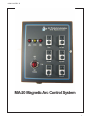
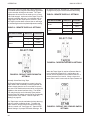
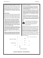
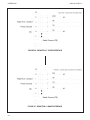
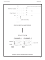
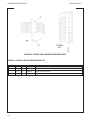
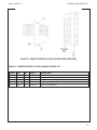
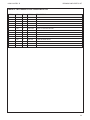
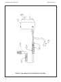
! IMPORTANT !
- For Your Safety Read this manual before
installing or using this equipment
ARC PRODUCTS, INC
MA-20 MAGNETIC ARC CONTROL
OPERATIONS AND SERVICE MANUAL
1245 30th Street
San Diego, CA 92154-3477
619-628-1022
619-628-1028 FAX
[email protected]
[email protected]
www.ap-automation.com
www.arc-products.com
THANK YOU!!!
. . . for purchasing Arc Products Equipment. Our commitment to you is to provide an ever expanding family of quality arc positioning equipment, controller and
accessories. Please take the time to read the following pages as they contain
important information regarding proper use of this product and of welding/cutting
safety and procedures.
WHO DO I CONTACT
For help:
• Contact your distributor
For additional information, such as,
Technical Manuals, Service and
Parts, Circuit and Wire Diagrams,
User’s Guides, Distributor Directories
• Contact your distributor
To file a claim for loss or damage
during shipment
• Contact your delivering carrier
For assistance in filing or settling
claims,
• contact your distributor and/or
equipment manufacturer’s Transportation Department
How to contact Arc Products:
Call:
619-628-1022
Fax:
619-628-1028
E-mail: [email protected]
[email protected]
Write: Arc Products
Attn: Customer Service
1245 30th Street
San Diego, CA 92154
ALWAYS PROVIDE MODEL NAME AND PART NUMBER
OVERVIEW
0600-0312 REV. D
Overview
OVERVIEW
IV
TABLE OF CONTENTS
V
TABLE OF TABLES
VII
TABLE OF FIGURES
VIII
SAFETY
SAFETY PRECAUTIONS
ADDITIONAL SAFETY HAZARDS
X
XII
MA-20 MAGNETIC ARC CONTROL SYSTEM
DESCRIPTION OF EQUIPMENT
3
INSTALLATION
6
OPERATION
17
MAINTENANCE
25
DRAWING AND PARTS LIST
27
TROUBLESHOOTING
43
CIRCUIT DESCRIPTIONS
45
SCHEMATICS AND BLOCK DIAGRAMS
47
INDEX
INDEX
iv
53
0600-0312 REV. D
TABLE OF CONTENTS
Table of Contents
OVERVIEW. . . . . . . . . . . . . . . . . . . . . . . . . . . IV
TABLE OF CONTENTS . . . . . . . . . . . . . . . . . . . . . . . V
TABLE OF TABLES . . . . . . . . . . . . . . . . . . . . . . . . VII
TABLE OF FIGURES . . . . . . . . . . . . . . . . . . . . . . . VIII
SAFETY
SAFETY PRECAUTIONS
DEFINITIONS . . . . . . . . . . . . . . . . . . . . . . . . . . X
NOTE
. . . . . . . . . . . . . . . . . . . . . . . . . . . . X
CAUTION . . . . . . . . . . . . . . . . . . . . . . . . . . . X
WARNING . . . . . . . . . . . . . . . . . . . . . . . . . . . X
DANGER. . . . . . . . . . . . . . . . . . . . . . . . . . . . X
SAFETY INFORMATION . . . . . . . . . . . . . . . . . . . . . . . X
ELECTRIC SHOCK . . . . . . . . . . . . . . . . . . . . . . . . X
FIRE SAFETY . . . . . . . . . . . . . . . . . . . . . . . . . . XI
ADDITIONAL SAFETY HAZARDS
FIRE AND EXPLOSION . . . . . . . .
FALLING EQUIPMENT . . . . . . . . .
HOT PARTS . . . . . . . . . . . .
MOVING PARTS . . . . . . . . . . .
MAGNETIC FIELDS CAN AFFECT PACEMAKERS
WELDING WIRE . . . . . . . . . . .
FLYING PIECES OF METAL OR DIRT . . . .
OVERHEATED EQUIPMENT . . . . . . .
HIGH FREQUENCY . . . . . . . . . .
SAFETY REFERENCES . . . . . . . .
.
.
.
.
.
.
.
.
.
.
.
.
.
.
.
.
.
.
.
.
.
.
.
.
.
.
.
.
.
.
.
.
.
.
.
.
.
.
.
.
.
.
.
.
.
.
.
.
.
.
.
.
.
.
.
.
.
.
.
.
.
.
.
.
.
.
.
.
.
.
.
.
.
.
.
.
.
.
.
.
.
.
.
.
.
.
.
.
.
.
.
.
.
.
.
.
.
.
.
.
.
.
.
.
.
.
.
.
.
.
.
.
.
.
.
.
.
.
.
.
.
.
.
.
.
.
.
.
.
.
.
.
.
.
.
.
.
.
.
.
XII
XII
XII
XII
XII
XII
XII
XII
XII
XII
MA-20 MAGNETIC ARC CONTROL SYSTEM
DESCRIPTION OF EQUIPMENT
DESCRIPTION OF EQUIPMENT . .
MA-20 CONTROL UNIT . . . . .
MAGNETIC ARC CONTROL PROBES
MP-1 PROBE . . . . . . .
MP-100 PROBE . . . . . .
MP-2 PROBE
. . . . . .
MP-22 PROBE . . . . . .
.
.
.
.
.
.
.
.
.
.
.
.
.
.
.
.
.
.
.
.
.
.
.
.
.
.
.
.
.
.
.
.
.
.
.
.
.
.
.
.
.
.
.
.
.
.
.
.
.
.
.
.
.
.
.
.
.
.
.
.
.
.
.
.
.
.
.
.
.
.
.
.
.
.
.
.
.
.
.
.
.
.
.
.
.
.
.
.
.
.
.
.
.
.
.
.
.
.
.
.
.
.
.
.
.
.
.
.
.
.
.
.
.
.
.
.
.
.
.
.
.
.
.
.
.
.
3
3
3
3
3
4
4
.
.
.
.
.
.
.
.
.
.
.
.
.
.
.
.
.
.
.
.
.
.
.
.
.
.
.
.
.
.
.
.
.
.
.
.
.
.
.
.
.
.
.
.
.
.
.
.
.
.
.
.
.
.
.
.
.
.
.
.
.
.
.
.
.
.
.
.
.
.
.
.
.
.
.
.
.
.
.
.
.
.
.
.
.
.
.
.
.
.
.
.
.
.
.
.
.
.
.
.
.
.
.
.
.
.
.
.
.
.
.
.
.
.
.
.
.
.
.
.
.
.
.
.
.
.
.
.
.
.
.
.
.
.
.
.
.
.
.
.
.
.
.
.
6
6
6
6
6
6
6
7
INSTALLATION
INSTALLATION . . . . . . . .
GENERAL SETUP . . . . . . .
OPTIONS AND SPECIALS . . . .
CONTROL UNIT LOCATION . . .
MAGNETIC ARC PROBE MOUNTING
MP-1 & MP-100 . . . . . .
MP-2 . . . . . . . . .
MP-22 . . . . . . . . .
OPERATION
OPERATION . . . . . . . . . . .
GENERAL OPERATIONAL DESCRIPTION .
CONTROL FEATURES & FUNCTIONS
. .
REMOTE / PANEL POSITION CONTROL
STABILIZE / OSCILLATE
. . . . .
SWEEP . . . . . . . . . . .
.
.
.
.
.
.
.
.
.
.
.
.
.
.
.
.
.
.
.
.
.
.
.
.
.
.
.
.
.
.
.
.
.
.
.
.
.
.
.
.
.
.
.
.
.
.
.
.
.
.
.
.
.
.
.
.
.
.
.
.
.
.
.
.
.
.
.
.
.
.
.
.
.
.
.
.
.
.
.
.
.
.
.
.
.
.
.
.
.
.
17
17
17
17
17
17
v
TABLE OF CONTENTS
0600-0312 REV. D
LEFT & RIGHT DWELL . . . . . . . . .
AMPLITUDE . . . . . . . . . . . .
POSITION . . . . . . . . . . . . .
FINAL TAPER . . . . . . . . . . . .
REMOTE START . . . . . . . . . . .
NORMALLY OPEN START . . . . . .
NORMALLY CLOSED START . . . . .
NORMALLY OPEN START USING TAPER .
NORMALLY CLOSED START USING TAPER
INSTALLATION . . . . . . . . . . . . .
.
.
.
.
.
.
.
.
.
.
.
.
.
.
.
.
.
.
.
.
.
.
.
.
.
.
.
.
.
.
.
.
.
.
.
.
.
.
.
.
.
.
.
.
.
.
.
.
.
.
.
.
.
.
.
.
.
.
.
.
.
.
.
.
.
.
.
.
.
.
.
.
.
.
.
.
.
.
.
.
.
.
.
.
.
.
.
.
.
.
.
.
.
.
.
.
.
.
.
.
.
.
.
.
.
.
.
.
.
.
.
.
.
.
.
.
.
.
.
.
17
17
17
17
18
18
19
19
20
21
MAINTENANCE
MAINTENANCE . . . . . . . . .
MAINTENANCE REQUIREMENTS . . .
CONTROL UNIT . . . . . . . . .
PROBES ASSEMBLIES. . . . . . .
CABLE ASSEMBLY . . . . . . . .
PREVENTIVE MAINTENANCE SCHEDULE
MONTHLY MAINTENANCE . . . .
PROBE ASSEMBLIES . . . . .
PROPER FUNCTION . . . .
TEST . . . . . . . . .
QUARTERLY MAINTENANCE . . .
SEMI ANNUAL MAINTENANCE . .
CONTROL UNIT ASSEMBLY . . .
.
.
.
.
.
.
.
.
.
.
.
.
.
.
.
.
.
.
.
.
.
.
.
.
.
.
.
.
.
.
.
.
.
.
.
.
.
.
.
.
.
.
.
.
.
.
.
.
.
.
.
.
.
.
.
.
.
.
.
.
.
.
.
.
.
.
.
.
.
.
.
.
.
.
.
.
.
.
.
.
.
.
.
.
.
.
.
.
.
.
.
.
.
.
.
.
.
.
.
.
.
.
.
.
.
.
.
.
.
.
.
.
.
.
.
.
.
.
.
.
.
.
.
.
.
.
.
.
.
.
.
.
.
.
.
.
.
.
.
.
.
.
.
.
.
.
.
.
.
.
.
.
.
.
.
.
.
.
.
.
.
.
.
.
.
.
.
.
.
.
.
.
.
.
.
.
.
.
.
.
.
.
.
.
.
.
.
.
.
.
.
.
.
.
.
.
.
.
.
.
.
.
.
.
.
.
.
.
25
25
25
25
25
25
25
25
25
25
25
25
25
.
.
.
.
.
.
.
.
.
.
.
.
.
.
.
.
27
TROUBLESHOOTING . . . . . . . . . . .
RECOMMENDED SPARES FOR TROUBLESHOOTING
PROBLEM 1. . . . . . . . . . . . .
PROBLEM 2. . . . . . . . . . . . .
PROBLEM 3. . . . . . . . . . . . .
.
.
.
.
.
.
.
.
.
.
.
.
.
.
.
.
.
.
.
.
.
.
.
.
.
.
.
.
.
.
.
.
.
.
.
.
.
.
.
.
.
.
.
.
.
.
.
.
.
.
.
.
.
.
.
.
.
.
.
.
43
43
43
43
43
DRAWING AND PARTS LIST
DRAWING AND PARTS LIST .
.
.
.
.
TROUBLESHOOTING
CIRCUIT DESCRIPTIONS
CIRCUIT DESCRIPTIONS . .
SYSTEM WIRING DIAGRAM .
MAIN BOARD ASSEMBLY . .
.
.
.
.
.
.
.
.
.
.
.
.
.
.
.
.
.
.
.
.
.
.
.
.
.
.
.
.
.
.
.
.
.
.
.
.
.
.
.
.
.
.
.
.
.
.
.
.
.
.
.
.
.
.
.
.
.
.
.
.
45
45
45
SCHEMATICS AND BLOCK DIAGRAMS .
.
.
.
.
.
.
.
.
.
.
.
.
.
.
.
.
47
INDEX .
.
.
.
.
.
.
.
.
.
.
.
.
.
.
.
.
53
SCHEMATICS AND BLOCK DIAGRAMS
INDEX
vi
.
.
.
.
.
.
.
.
.
.
.
0600-0312 REV. D
TABLE OF TABLES
Table of Tables
MA-20 MAGNETIC ARC CONTROL SYSTEM
DESCRIPTION OF EQUIPMENT
3
INSTALLATION
6
TABLE 1 - MA-20 MAGNETIC ARC CONTROL SPECIFICATIONS . . . . . . . . .
TABLE 2 - MA-20 MAGNETIC ARC CONTROL SYSTEM COMPONENTS SPECIFICATIONS .
TABLE 3 - MP-1 MAGNETIC ARC PROBE ASSEMBLY SPECIFICATIONS. . . . . . .
TABLE 4 - MP-100 MAGNETIC ARC PROBE ASSEMBLY SPECIFICATIONS . . . . . .
TABLE 5 - MP-2 MAGNETIC ARC PROBE ASSEMBLY SPECIFICATIONS. . . . . . .
TABLE 6 - MP-22 MAGNETIC ARC PROBE ASSEMBLY SPECIFICATIONS . . . . . .
OPERATION
8
9
10
11
12
13
17
TABLE 7 - REMOTE START N.O. INHIBIT SETTINGS
TABLE 8 - REMOTE START N.C. INHIBIT SETTINGS
TABLE 9 - REMOTE TAPER N.C. SETTINGS . . .
TABLE 10 - REMOTE TAPER N.O. SETTINGS . .
.
.
.
.
.
.
.
.
.
.
.
.
.
.
.
.
.
.
.
.
.
.
.
.
.
.
.
.
.
.
.
.
.
.
.
.
.
.
.
.
.
.
.
.
.
.
.
.
.
.
.
.
MAINTENANCE
25
DRAWING AND PARTS LIST
27
TABLE 11 - MA-20 MAGNETIC ARC CONTROL PARTS LIST . .
TABLE 12 - POWER SWITCH ASSEMBLY PARTS LIST . . . .
TABLE 13 - TRANSFORMER ASSEMBLY PARTS LIST . . . . .
TABLE 14 - PROBE CABLE HARNESS PARTS LIST . . . . .
TABLE 15 - REMOTE INTERFACE CABLE HARNESS PARTS LIST .
TABLE 16 - MP-1 MAGNETIC ARC PROBE PARTS LIST . . . .
TABLE 17 - MP-2 MAGNETIC ARC PROBE PART LIST . . . .
TABLE 18 - MP-22 MAGNETIC ARC PROBE PARTS LIST . . . .
TABLE 19 - MP-100 MAGNETIC ARC PROBE PARTS LIST . . .
TABLE 20 - VOLTAGE SELECTOR SWITCH ASSEMBLY PARTS LIST
.
.
.
.
.
.
.
.
.
.
.
.
.
.
.
.
.
.
.
.
.
.
.
.
.
.
.
.
.
.
.
.
.
.
.
.
.
.
.
.
.
.
.
.
.
.
.
.
.
.
.
.
.
.
.
.
.
.
.
.
.
.
.
.
.
.
.
.
.
.
.
.
.
.
.
.
.
.
.
.
.
.
.
.
.
.
.
.
.
.
.
.
.
.
.
.
.
.
.
.
.
.
.
.
TROUBLESHOOTING
TABLE 21 - TROUBLESHOOTING . . . .
TABLE 22 - RECOMMENDED SPARE PARTS
TABLE 23 - VOLTAGE POINTS MAIN BOARD
18
19
20
20
29
30
31
32
33
35
37
39
41
42
43
.
.
.
.
.
.
.
.
.
.
.
.
.
.
.
.
.
.
.
.
.
43
43
43
CIRCUIT DESCRIPTIONS
45
SCHEMATICS AND BLOCK DIAGRAMS
47
vii
TABLE OF FIGURES
0600-0312 REV. D
Table of Figures
MA-20 MAGNETIC ARC CONTROL SYSTEM
DESCRIPTION OF EQUIPMENT
3
FIGURE 1 - MP-1 AND MP-100 MOUNTING METHOD, CROSS SEAM
FIGURE 2 - MP-1 AND MP-100 MOUNTING METHOD, ALONG SEAM
FIGURE 3 - MP-2 MOUNTING METHOD, ALONG SEAM . . . .
FIGURE 4 - MP-2 MOUNTING METHOD, CROSS SEAM . . . .
FIGURE 5 - MP-22 MOUNTING METHOD, ALONG SEAM . . . .
FIGURE 6 - MP-22 MOUNTING METHOD, CROSS SEAM . . . .
.
.
.
.
.
.
.
.
.
.
.
.
.
.
.
.
.
.
.
.
.
.
.
.
.
.
.
.
.
.
.
.
.
.
.
.
.
.
.
.
.
.
.
.
.
.
.
.
FIGURE 7 - MA-20 MAGNETIC ARC CONTROL UNIT . . . . . . . .
FIGURE 8 - MA-20 MAGNETIC ARC CONTROL SYSTEM COMPONENTS . .
FIGURE 9 - MP-1 MAGNETIC ARC PROBE ASSEMBLY . . . . . . .
FIGURE 10 - MP-100 MAGNETIC ARC PORBE ASSEMBLY . . . . . .
FIGURE 11 - MP-2 MAGNETIC ARC PROBE ASSEMBLY . . . . . . .
FIGURE 12 - MP-22 MAGNETIC ARC PROBE ASSEMBLY . . . . . .
FIGURE 13 - INTERCONNECTION DIAGRAM . . . . . . . . . .
FIGURE 14 - MA-20 MAGNETIC ARC CONTROL MOUNTING DIMENSIONS
FIGURE 15 - AMPLITUDE SETTINGS . . . . . . . . . . . . .
FIGURE 16 - POSITION SETTINGS . . . . . . . . . . . . . .
FIGURE 17 - SWEEP SETTINGS. . . . . . . . . . . . . . .
FIGURE 18 - DWELL SETTINGS . . . . . . . . . . . . . . .
.
.
.
.
.
.
.
.
.
.
.
.
.
.
.
.
.
.
.
.
.
.
.
.
.
.
.
.
.
.
.
.
.
.
.
.
.
.
.
.
.
.
.
.
.
.
.
.
.
.
.
.
.
.
.
.
.
.
.
.
FIGURE 19 - TAPER FUNCTION . . . . . . . . . .
FIGURE 20 - DEFAULT INHIBIT DIP SWITCH SETTINGS . .
FIGURE 21 - INHIBIT NC DIP SWITCH SETTINGS . . . .
FIGURE 22 - DEFAULT TAPER DIP SWITCH SETTINGS . .
FIGURE 23 - DEFAULT OSC / STAB DIP SWITCH SETTINGS
FIGURE 24 - TAPER NC DIP SWITCH SETTINGS . . . .
FIGURE 25 - REMOTE N.O. TAPER INTERFACE . . . .
FIGURE 26 - REMOTE N.C. TAPER INTERFACE . . . .
FIGURE 27 - REMOTE N.C. INHIBIT INTERFACE . . . .
FIGURE 28 - REMOTE N.O. INHIBIT INTERFACE . . . .
FIGURE 29 - DEFAULT POSITION DIP SWITCH SETTINGS .
.
.
.
.
.
.
.
.
.
.
.
.
.
.
.
.
.
.
.
.
.
.
.
.
.
.
.
.
.
.
.
.
.
.
.
.
.
.
.
.
.
.
.
.
.
.
.
.
.
.
.
.
.
.
.
INSTALLATION
6
OPERATION
8
9
10
11
12
13
14
15
16
16
16
16
17
.
.
.
.
.
.
.
.
.
.
.
.
.
.
.
.
.
.
.
.
.
.
.
.
.
.
.
.
.
.
.
.
.
.
.
.
.
.
.
.
.
.
.
.
.
.
.
.
.
.
.
.
.
.
.
MAINTENANCE
27
FIGURE 30 - MA-20 MAIN BOARD LAYOUT . . . . . . . . . . .
FIGURE 31 - MA-20 MAGNETIC ARC CONTROL EXPLODED VIEW . . .
FIGURE 32 - POWER SWITCH ASSEMBLY EXPLODED VIEW . . . . .
FIGURE 33 - TRANSFORMER ASSEMBLY EXPLODED VIEW . . . . .
FIGURE 34 - PROBE CABLE HARNESS EXPLODED VIEW . . . . . .
FIGURE 35 - REMOTE INTERFACE CABLE HARNESS EXPLODED VIEW .
FIGURE 36 - MP-1 MAGNETIC ARC PROBE EXPLODED VIEW
. . . .
FIGURE 37 - MP-2 MAGNETIC ARC PROBE EXPLODED VIEW . . . . .
FIGURE 38 - MP-22 MAGNETIC ARC PROBE EXPLODED VIEW . . . .
FIGURE 39 - MP-100 MAGNETIC ARC PROBE EXPLODED VIEW . . . .
FIGURE 40 - VOLTAGE SELECTOR SWITCH ASSEMBLY EXPLODED VIEW
.
.
.
.
.
.
.
.
.
.
.
.
.
.
.
.
.
.
.
.
.
.
.
.
.
.
.
.
.
.
.
.
.
.
.
.
.
.
.
.
.
.
.
.
.
.
.
.
.
.
.
.
.
.
.
TROUBLESHOOTING
45
.
.
.
.
.
.
.
.
.
.
.
.
.
.
.
.
.
.
SCHEMATICS AND BLOCK DIAGRAMS
FIGURE 42 - MP-1 MAGNETIC ARC PROBE BLOCK DIAGRAM.
27
28
30
31
32
33
34
36
38
40
42
43
CIRCUIT DESCRIPTIONS
FIGURE 41 - MA-20 MAGNETIC ARC CONTROL SIGNAL FLOW
18
19
19
20
20
20
21
22
22
23
23
25
DRAWING AND PARTS LIST
viii
4
4
5
5
5
5
46
47
47
0600-0312 REV. D
TABLE OF FIGURES
FIGURE 43 - MP-2 MAGNEITC ARC PROBE BLOCK DIAGRAM. . . . . . .
FIGURE 44 - MA-20 MAGNETIC ARC CONTROL BLOCK DIAGRAM . . . . .
FIGURE 45 - MA-20 MAGNETIC ARC CONTROL BLOCK DIAGRAM (CONT.) . .
FIGURE 46 - MP-22 MAGNETIC ARC PROBE BLOCK DIAGRAM . . . . . .
FIGURE 47 - MP-100 MAGNETIC ARC PROBE BLOCK DIAGRAM . . . . . .
FIGURE 48 - MA-20 MAGNETIC ARC CONTROL INTERFACE CABLE SCHEMATIC
.
.
.
.
.
.
.
.
.
.
.
.
.
.
.
.
.
.
47
48
49
50
50
51
ix
SAFETY
0600-0312 REV. D
SAFETY
SAFETY PRECAUTIONS
SAFETY INFORMATION
THIS MANUAL HAS BEEN DESIGNED FOR EXPERIENCED WELDING AND CUTTING EQUIPMENT
OPERATORS AND MUST BE READ COMPLETELY
BEFORE USING THIS EQUIPMENT. IF YOU LACK
EXPERIENCE OR ARE UNFAMILIAR WITH THE
PRACTICES AND SAFE OPERATION OF WELDING
AND CUTTING EQUIPMENT, PLEASE CONSULT
YOUR FOREMAN. DO NOT ATTEMPT TO INSTALL,
OPERATE, OR PERFORM MAINTENANCE ON THIS
EQUIPMENT UNLESS YOU ARE QUALIFIED AND
HAVE READ AND UNDERSTOOD THIS MANUAL. IF
IN DOUBT ABOUT INSTALLING OR OPERATING
THIS EQUIPMENT, CONTACT YOUR DISTRIBUTOR
OR THE CUSTOMER SERVICE DEPARTMENT OF
ARC PRODUCTS.
Safety is a combination of good judgment and proper
training. Operation and maintenance of any arc welding and cutting equipment involves potential hazards.
Individuals who are unfamiliar with cutting and welding equipment, use faulty judgment or lack proper
training, may cause injury to themselves and others.
Personnel should be alerted to the following potential
hazards and the safeguards necessary to avoid possible injury. In addition, before operating this equipment,
you should be aware of your employer's safety regulations.
BE SURE TO READ THIS MANUAL BEFORE INSTALLING OR USING THIS
EQUIPMENT.
DEFINITIONS
Throughout this manual, NOTE, CAUTION,
WARNING and DANGER are inserted to call attention
to particular information. The methods used to identify
these highlights and the purpose for which each is
used, are as follows:
NOTE
Operational, procedural, and background information which aids the operator in the use
of the machine, helps the service personnel
in the performance of maintenance, and
prevents damage to the equipment.
CAUTION
An operational procedure which, if not followed, may cause minor injury to the operator, service personnel and/or bystanders.
WARNING
An operational procedure which, if not followed, may cause severe injury to the operator, service personnel and/or bystanders.
DANGER
An operational procedure which, if not followed, will cause severe injury or even
death to the operator, service personnel or
bystanders.
BE SURE TO READ AND FOLLOW ALL
AVAILABLE SAFETY REGULATIONS BEFORE USING THIS EQUIPMENT.
ELECTRIC SHOCK
THE VOLTAGES PRESENT IN THE
WELDING AND CUTTING ENVIRONMENT
CAN CAUSE SEVERE BURNS TO THE
BODY OR FATAL SHOCK. THE SEVERITY
OF ELECTRICAL SHOCK IS DETERMINED BY THE PATH AND THE AMOUNT
OF CURRENT THROUGH THE BODY.
A Install and continue to maintain equipment
according to USA Standard C1, National Electric Code.
B
Never allow live metal parts to touch bare
skin or any wet clothing. Use only dry gloves.
C
When welding or cutting in a damp area,
or when standing on metal, make sure you are
well insulated by wearing dry gloves, rubber
soled shoes, and by standing on a dry board
or platform.
D
Do not use worn or damaged welding or
torch cables. Do not overload the cables. Use
well maintained equipment.
E
When not welding/cutting, turn equipment
OFF. Accidental grounding can cause overheating and create a fire hazard. Do not coil or
loop the cable around parts of the body.
F
The ground cable should be connected to
the work piece as close to the work area as
possible. Grounds connected to building
framework or other locations remote to the
x
0600-0312 REV. D
work area reduce efficiency and increase the
potential hazard of electric shock. Avoid the
possibility of the welding or cutting current
passing through lifting chains, crane cables or
other electrical paths.
G
Keep everything dry you might touch, including clothing, the work area, welding gun,
torch and welding or cutting machines. Fix water leaks immediately. Do not operate equipment standing in water.
H
Never use a cutting torch or welding gun
which is damaged or contains cracked housing.
I
Refer to AWS-Z49.1 for grounding recommendations.
SKIN AND EYE BURNS RESULTING
FROM BODY EXPOSURE TO ELECTRIC-ARC WELDING AND CUTTING
RAYS OR HOT METAL CAN BE MORE
SEVERE THAN SUNBURN.
A Use a proper face shield fitted with the cor-
rect filter (#10 or greater) and cover plates to
protect your eyes, face, neck and ears from
the sparks and rays of the cutting/welding arc
when cutting/welding or observing cutting/welding. Warn bystanders not to watch
the arc and not to expose themselves to the
cutting/welding arc rays or to hot metal.
B
Wear flameproof gauntlet-type gloves, a
heavy long-sleeve shirt, cuff-less trousers,
high-topped shoes, and a welding helmet or
cap (for hair protection) to protect the skin
from arc rays and hot sparks or hot metal.
C
Protect other nearby personnel from arc
rays and hot sparks with a suitable non-flammable partition.
D Always wear safety glasses or goggles
when in a cutting or welding area. Use safety
glasses with side shields or goggles when
chipping slag or grinding. Chipped slag is hot
and may travel a considerable distance. Bystanders should also wear safety glasses or
goggles.
E
Compressed gas cylinders are potentially
dangerous, refer to the suppliers for proper
handling procedures.
F
Wear ear plugs or other ear protection devices when operating cutting or welding equipment.
FIRE SAFETY
SAFETY
A Move all combustible materials well away
from the cutting area or completely cover materials with a non-flammable covering. Combustible materials include but are not limited to
wood, clothing, sawdust, gasoline, kerosene,
paints, solvents, natural gases, acetylene, propane, and similar articles.
B
Do not weld, cut or perform other hot work
on used barrels, drums, tanks or other containers until they have been completely
cleaned. There must be no substances in the
container which might produce flammable or
toxic vapors.
C
For fire protection, have suitable extinguishing equipment handy for instant use.
WELDING AND CUTTING FUMES AND
GASES, PARTICULARLY IN CONFINED
SPACES, CAN CAUSE DISCOMFORT
AND PHYSICAL HARM IF INHALED
OVER AN EXTENDED PERIOD OF TIME.
A At all times, provide adequate ventilation in
the welding and cutting area by either natural
or mechanical means. Do not weld or cut on
galvanized, zinc, lead, beryllium or cadmium
materials unless positive mechanical ventilation is provided to prevent inhaling fumes and
gases from these materials.
B
Do not weld or cut in locations close to
chlorinated hydrocarbon vapors coming from
degreasing or spraying operations. The heat
of arc rays can react with solvent vapors to
form phosgene, a highly toxic gas, and other
irritant gases.
C
If you develop momentary eye, nose or
throat irritation during welding or cutting, it is
an indication that the ventilation is not adequate. Stop work and take the necessary
steps to improve ventilation in the welding or
cutting area. Do not continue to weld or cut if
physical discomfort persists.
D
Use an air supplied respirator if ventilation
is not adequate to remove all fumes and
gases.
E
Beware of gas leaks. Welding or cutting
gases containing argon are denser than air
and will replace air when used in confined
spaces. Do not locate gas cylinders in confined spaces. When not in use, shut OFF the
gas supply at its source.
Refer to AWS Standard Z49.1 for specific ventilation
recommendations.
HOT SLAG OR SPARKS CAN CAUSE A
SERIOUS FIRE WHEN IN CONTACT WITH
COMBUSTIBLE SOLIDS, LIQUIDS OR
GASES.
xi
SAFETY
0600-0312 REV. D
ADDITIONAL SAFETY HAZARDS
FIRE AND EXPLOSION
Fire and Explosion can result from placing
units on, over, or near combustible surfaces.
• Do not install units on, over, or near com-
bustible surfaces.
• Do not install unit near flammables.
FALLING EQUIPMENT
Falling Equipment can cause serious personal injury and equipment damage.
• Use lifting eyes to lift unit only, not running
gear, gas cylinders, or any other accessories.
• Use equipment of adequate capacity to lift
units.
• If using fork lifts to move units, be sure forks
are long enough to extend beyond opposite
side of the unit.
• Do not press gun trigger until instructed to
do so.
• Do not point the gun toward any part of the
body, other people, or any metal when
threading welding wire through the gun.
FLYING PIECES OF METAL OR DIRT
Flying pieces of metal or dirt can injure
eyes.
• Wear safety glasses with side shields or
face shields.
OVERHEATED EQUIPMENT
High output power for long durations can
cause equipment to overheat.
• Allow cooling periods.
• Reduce current or reduce duty cycle before
starting to weld again.
• Follow rated duty cycle.
HIGH FREQUENCY
HOT PARTS
Hot parts can cause severe burns.
High Frequency can cause electrical interference.
• Do not touch hot parts bare handed.
• Take appropriate precautions to shield sen-
• Allow cooling period before working on gun
or torch.
MOVING PARTS
Moving Parts can cause injury.
• Keep away from moving parts, such as
fans.
• Keep all doors, panels, covers, and guards
closed and securely in place.
• Keep away from pinch points, such as mechanical slides, drive rolls, carriage assemblies, etc.
MAGNETIC FIELDS CAN AFFECT
PACEMAKERS
Magnetic Fields from High Currents can affect pacemaker operation.
• Pacemaker wearers should keep away.
• Wearers of pacemakers should consult their
doctors before going near arc welding,
gouging, plasma cutting, or spot welding
operations.
WELDING WIRE
Welding wire can cause puncture wounds.
xii
sitive electronic equipment, such as computers, Programmable Logic Controllers,
etc.
• Be sure to ground each component of the
system to one ground point, i.e., Earth
Ground (Earth) or Protective Earth (PE).
SAFETY REFERENCES
The following publications provide additional information on important welding safeguards.
A ANSI/ASC 249.1-1988, American National
Standard "Safety in Welding and Cutting".
B
Bulletin No. F4-1, "Recommended Safe
Practices for the Preparation for Welding and
Cutting Containers and Piping that have held
Hazardous Substances".
C
OSHA Safety and Health Standards,
29CFR 1910, available from the United States
Department of Labor, Washington, DC 20210.
D
NFPA Standard 51B, "Fire Prevention in
Use of Cutting and Welding Processes", available from the National Fire Protection Association, 470 Atlantic Avenue, Boston, MA
00210.
E
NEMA Standards Publication/No.
EW1-1989, Electric Arc-Welding Apparatus,
approved as ANSI C87.1-1989. Available from
National Electrical Manufacturers Association,
155 E. 44th Street, New York, NY 10017.
0600-0312 REV. D
MA-20 Magnetic Arc Control System
1
0600-0312 REV. D
2
0600-0312 REV. D
DESCRIPTION OF EQUIPMENT
The AP AUTOMATION MA-20 Magnetic Arc Control
System is a precise, controllable means for oscillating, stabilizing, or positioning a welding arc. This allows the operator to control heat distribution, minimize
undercutting, reduce porosity, improve penetration,
provide uniform sidewall fusion and improve the overall integrity of the weld. Used with the Model MP-1,
MP-100, MP-2, and MP-22 Probes or the
Cyclomatic™ 4604, 4608C, and 4615 Probes.
MA-20 CONTROL UNIT
The control unit is a heavy gauge steel enclosure containing the electronic circuitry used in the system. A
microprocessor and other solid state circuits are used
to provide long, trouble-free operation. The control
unit operates on 115/230VAC, 50/60 Hz commercial
power, capable of supplying approximately 2 amps
peak current. The unit has a lighted power switch and
fuse holder mounted on the exterior of the unit. See
Table 1 - MA-20 Magnetic Arc Control Specifications,
Table 2 - MA-20 Magnetic Arc Control System
Components Specifications, Figure 7 - MA-20 Magnetic Arc Control Unit, and Figure 8 - MA-20 Magnetic
Arc Control System components for additional
specifications.
The system is operated using the controls, potentiometers, pushbuttons located on the front panel. Additional switches are located on the inside of the control
unit on the main board via DIP switches. A heatsink
mounted on the inside of the control unit allows adequate cooling for the heat dissipating devices.
Two connectors located on the bottom of the unit provide for connection of the probe cable and a remote
interface cable.
The MA-20 system is primarily intended for use with
the TIG (GTAW) process, but can also be used with
the PLASMA (PAW) welding process. Additionally,
the MA-20 System can be used with spray MIG and
Sub Arc processes. With this system, the operator
can widen or narrow the weld bead as required to provide control of the heat affected zone, undercutting,
and irregular joint edges. The controlled magnetic
field also reduces arc blow and arc wander, while the
motion of the arc stirs the molten weld puddle, reducing porosity and providing a more uniform bead surface pattern.
The MA-20 is a simple, reliable control with an oscillating frequency range up to 50 Hz. The Pulse Width
Modulation (PWM) design provides a constant magnetic field for a given amplitude setting over the entire
frequency range. Control functions allow independent
DESCRIPTION OF EQUIPMENT
control of each of the key waveform parameters, and
left and right dwell intervals are also independently
adjustable. The control unit is convection cooled, allowing for less power dissipation and lower operating
temperatures.
The top panel or door of the control unit contains all
the controls needed for operation. There are three
Light Emitting Diode (LED) indicators in a pattern to
the left of the control knobs. Each lamp will illuminate
alternately during arc oscillation. When power is applied to the Control Unit, the Power On LED will also
illuminate.
The MA-20 Control unit has additional features selected from inside the control enclosure. These features, Stabilize/Oscillate mode (STAB/OSC) and
Remote / Panel Position Control, are selected via DIP
Switches on the main board.
Stabilize / Oscillate mode allows the operator the ability to oscillate the arc either across the seam or along
the seam depending on how the probe is mounted on
the torch (Oscillate Mode), or to stabilize the arc, positioning the arc in the desired location (Stabilize
Mode).
Remote / Panel Position Control allow the operator to
control the arc position of the each axis from a remote
potentiometer or PLC with an analog output, or from
the front panel controls (default).
MAGNETIC ARC CONTROL PROBES
MP-1 PROBE
The MP-1 is a single-tip, water-cooled probe that
adapts to conventional torches. The MP-1 works well
in tight clearances and is primarily used to weave the
arc across the seam or to stabilize the arc. On page
10 is Table 3 - MP-1 Magnetic Arc Probe Assembly
Specifications and Figure 9 - MP-1 Magnetic Arc
Probe Assembly for detailed dimensions and specifications.
MP-100 PROBE
The MP-100 probe incorporates the latest magnetic
technologies. Though similar to the MP-1 probe, the
new MP-100 probe has a much higher gauss strength
and three times the efficiency of the MP-1. The
MP-100 does not require water cooling; however, it
does allow for optional water cooling. For added convenience and flexibility, it also features a detachable
control cable. This single-axis probe adapts to conventional torches. A variety of return rings and tips are
available for different configurations. See page 11 is
Table 4 - MP-100 Magnetic Arc Probe Assembly
Specifications and Figure 10 - MP-100 Magnetic Arc
3
DESCRIPTION OF EQUIPMENT
0600-0312 REV. D
Porbe Assembly for detailed dimensions and specifications.
MP-2 PROBE
The dual-tip MP-2 slips over a conventional TIG torch
and can be used either for cross-seam arc weaving or
in-line arc weaving. In-line weave is primarily used in
tube mills to preheat the tube, pishing the arc into the
direction of travel, giving increased weld travel
speeds. See page 12 is Table 5 - MP-2 Magnetic Arc
Probe Assembly Specifications and Figure 11 - MP-2
Magnetic Arc Probe Assembly for detailed dimensions
and specifications.
MP-22 PROBE
This twin-tip side-mount unit is capable of delivering
the full 600 gauss magnetic field to the welding arc
area. Though normally used in an air-cooled mode, if
necessary, the MP-22 can also be water-cooled. For
detailed specifications on the MP-22 probe, see Table
6 - MP-22 Magnetic Arc Probe Assembly
Specifications and Figure 12 - MP-22 Magnetic Arc
Probe Assembly on page 13.
FIGURE 1 - MP-1 AND MP-100 MOUNTING
METHOD, CROSS SEAM
4
FIGURE 2 - MP-1 AND MP-100 MOUNTING
METHOD, ALONG SEAM
0600-0312 REV. D
DESCRIPTION OF EQUIPMENT
FIGURE 3 - MP-2 MOUNTING METHOD, ALONG
SEAM
FIGURE 4 - MP-2 MOUNTING METHOD, CROSS
SEAM
FIGURE 5 - MP-22 MOUNTING METHOD,
ALONG SEAM
FIGURE 6 - MP-22 MOUNTING METHOD, CROSS
SEAM
5
INSTALLATION
INSTALLATION
GENERAL SETUP
A standard MA-20 Magnetic Arc Control system is
shown in Figure 13 - Interconnection Diagram, with
the necessary interconnects shown schematically.
The major parts required for installing this system are
listed below. Check all items for damage when unpacking.
System should consist of the following:
• Control Unit
• Probe Assembly
• Remote Interface Cable
• Power Cord
• Operators Manual
0600-0312 REV. D
and Figure 31 - MA-20 Magnetic Arc Control
Exploded View). The operator may select the proper
input voltage using a small slotted screwdriver. The
mounting dimensions of the control unit are shown in
Figure 14 - MA-20 Magnetic Arc Control Mounting Dimensions, should the user choose to install the
MA-20 on a fixture or control panel.
MAGNETIC ARC PROBE MOUNTING
The MP-1, MP-22, and MP-100 Probes will mount on
any machine torch with a body diameter from 1.31
inches to 2 inches. The MP-2 Probe will mount on
any machine torch with a body diameter of 1.625
inches or less. (See review the figures and tables on
the following pages beginning on page 10 for dimensional references.)
MP-1 & MP-100
• Back off the two socket screws which secure the
OPTIONS AND SPECIALS
Options for the MA-20 System may be purchased
from Arc Products. Specials include probe tips, probe
tip extensions and extension length cables designed
to fit a particular mechanical configuration when the
standard tips or cables will not.
The installation of the MA-20 System is very easy and
can be accomplished on most automatic or semiautomatic setups within minutes.
CONTROL UNIT LOCATION
The MA-20 Control Unit should be placed in a location
which provides easy access to the controls and
proper air ventilation for cooling. To allow adequate
ventilation, maintain a minimum of 5 inches of unrestricted space between the control unit (sides) and the
nearest obstruction. The location should be selected
to minimize the amount of dust, dirt, moisture and corrosive vapors the Control Unit will be subjected to.
Please see Figure 14 - MA-20 Magnetic Arc Control
Mounting Dimensions for mounting hole patterns and
other dimensions.
NOTE
Although the control unit requires no
other electrical interfacing with any of the
users's other equipment, be sure to select the proper input voltage before plugging the unit into the ac power outlet! This unit
operates on either 110/220 VAC 50/60 hz power.
Be sure the Voltage Selector switch is in the
proper position for the power you are using!
The Voltage Selector switch is located on the outside
of the control unit near the AC power cord receptacle
(Refer to Figure 7 - MA-20 Magnetic Arc Control Unit
6
probe mounting bracket to the torch body.
• Slip the probe over the torch and align the tips approx-
imately even with the gas cup, or bottom of torch.
Tighten the 2 screws, then loosen the screws holding
the bracket to the probe in order to position the probe
on the torch body. (See Figure 2 - MP-1 and MP-100
Mounting Method, Along Seam and Figure 1 - MP-1
and MP-100 Mounting Method, Cross Seam beginning on page 4 for illustrations of probe-to-seam orientation.)
MP-2
The MP-2 probe is a torroidial design probe, where
the torch mounts through the center of the probe. To
make mounting this probe to a torch easier, torch
adapters are available, but are not required to mount
the probe to the torch.
• A) Select a suitable adapter for your torch (if neces-
sary).
Without adaptor: 1.625 in.
Adapter P/N 1030-0517: 1.500 in.
Adapter P/N 1026-0582: 1.455 in.
Adapter P/N 1026-0574: 1.380 in.
• Back off the three socket head cap screws which se-
cure the probe to the torch body.
• Slip the probe over the torch and align the tips approx-
imately even with the gas cup, or bottom of torch.
Tighten the three screws while insuring that the probe
remains centered on the torch body.
For probe-to-seam orientation, please refer to Figure
3 - MP-2 Mounting Method, Along Seam and Figure 4
- MP-2 Mounting Method, Cross Seam beginning on
page 4 for illustrations of this probes probe-to-seam
orientation.
0600-0312 REV. D
INSTALLATION
MP-22
The MP-22 probe has the strongest magnetic field
strength of all of the Magnetic Arc Probes. Under normal conditions, the MP-22 doesn’t need water cooling, but water cooling hoses and coolant can be
added to the probe during high amperage welding applications or when high amplitude settings are desired. See Figure 5 - MP-22 Mounting Method, Along
Seam and Figure 6 - MP-22 Mounting Method, Cross
Seam beginning on page 5 for mounting information
and Figure 12 - MP-22 Magnetic Arc Probe Assembly
on page 13 for additional probe specifications.
The MP-1 and MP-2 probes are water-cooled units
and require cooling water (40 psi max.) Be sure to
connect the probe to a circulating cooling system before starting operation, as severe damage to the
probe may result if the probe is not properly cooled.
Once mounting is complete, connect the probe to the
MA-20 Control Unit, then connect the control unit to
an AC power outlet.
NOTE
Be sure of select the correct input voltage
at the Voltage Selector switch matching
that which you intend to use before connect the control unit to an AC power outlet.
7
INSTALLATION
0600-0312 REV. D
FIGURE 7 - MA-20 MAGNETIC ARC CONTROL UNIT
TABLE 1 - MA-20 MAGNETIC ARC CONTROL SPECIFICATIONS
ITEM
DESCRIPTION
SPECIFICATIONS
Frequency
Oscillating Frequency
1.0 to 50 Hz maximum with Sweep at Zero
Amplitude
Oscillating Width
.25 inches on each side of the weld line (approximate)
Position
Arc Position
.25 inches on each side of the weld line (approximate)
Dwell
Left and Right Arc Dwell Time
100:1 on either side of the desired weld line
(continously adjustable)
Sweep
Transition Adjustment between either side
0 to 3 seconds transition adjustment between
left/right dwells
Taper
Trail off of Amplitude at the end of the weld cycle
0 to 15 seconds to match downslope time of the
welding power source
Controls
Frequency
Amplitude
Left / Right Dwell
Sweep
Taper
Stabilize / Oscillate Mode DIP Switches
Input
Power Requirements
90 - 132 VAC / 180 - 264 VAC 50/60 Hz
Control Unit
Enclosure
Standard NEMA Style Sealed enclosure
Probes
MA-20 can be used with these probes
MP-1
MP-2
MP-22
MP-100
8
Power Cable
Standard Length
8’ (1.8 M)
Remote Interface Cable
Standard Length
10’ (3 M)
Weight
Standard Weight
10 lbs. (4.1 Kg)
0600-0312 REV. D
INSTALLATION
FIGURE 8 - MA-20 MAGNETIC ARC CONTROL SYSTEM COMPONENTS
TABLE 2 - MA-20 MAGNETIC ARC CONTROL SYSTEM COMPONENTS SPECIFICATIONS
ITEM
SPECIFICATION
Control Unit
MA-20 Magnetic Arc Control
Probe Assembly
MP-1, MP-2, MP-22, MP-100 Probes
Cables
Power Cord Assembly
Remote Interface Cable Assembly
Probe Cable Assembly (MP-100 only)
Manual
MA-20 Operators and Service Manual
9
INSTALLATION
0600-0312 REV. D
FIGURE 9 - MP-1 MAGNETIC ARC PROBE ASSEMBLY
TABLE 3 - MP-1 MAGNETIC ARC PROBE ASSEMBLY SPECIFICATIONS
ITEM
DESCRIPTION
SPECIFICATION
Weld Current Rating
Arc Welding Amperage is limited due to heat and
strength of arc
600 amps 100% duty cycle
Cooling
Liquid cooling of the probe
1 quart or water per minute at 68 degrees F (20 C)
with a miximum water pressure of 40 PSI
Ship Weight
5 pounds (2.3Kg)
Cable Length
Control Cable Length
8 feet (2.4M)
Hose Length
Liquid Cooling Hose Length
12’ (3.6M)
Accessories
Tip Extensions
1” Tip Extension (1 required)
2” Tip Extension (1 required)
3” Tip Extension (1 required)
4” Tip Extension (1 required)
10
0600-0312 REV. D
INSTALLATION
FIGURE 10 - MP-100 MAGNETIC ARC PORBE ASSEMBLY
TABLE 4 - MP-100 MAGNETIC ARC PROBE ASSEMBLY SPECIFICATIONS
ITEM
DESCRIPTION
SPECIFICATION
Weld Current Rating
Arc Welding Amperage is limited due to heat and
strength of arc
600 amps 100% duty cycle
Cooling
Liquid cooling of the probe
1 quart or water per minute at 68 degrees F (20 C)
with a miximum water pressure of 40 PSI
Ship Weight
5 pounds (2.3Kg)
Cable Length
Control Cable Length
8 feet (2.4M)
Hose Length
Liquid Cooling Hose Length
12’ (3.6M) (Optional)
Accessories
Tip Extensions
Consult Factory
11
INSTALLATION
0600-0312 REV. D
FIGURE 11 - MP-2 MAGNETIC ARC PROBE ASSEMBLY
TABLE 5 - MP-2 MAGNETIC ARC PROBE ASSEMBLY SPECIFICATIONS
ITEM
DESCRIPTION
SPECIFICATION
Weld Current Rating
Arc Welding Amperage is limited due to heat and
strength of arc
400 amps 100% duty cycle
Cooling
Liquid cooling of the probe
1 quart or water per minute at 68 degrees F (20 C)
with a miximum water pressure of 40 PSI
Ship Weight
4 pounds (2.3Kg)
Cable Length
Control Cable Length
8 feet (2.4M)
Hose Length
Liquid Cooling Hose Length
12’ (3.6M)
Accessories
Probe Adaptors
1.380” (35.05 mm) Torch Adaptor
1.455” (39.96 mm) Torch Adaptor
1.500” (38.10 mm) Torch Adaptor
Tip Extensions
1.88” Replacement Extended Length Tips (2 req.)
2.38” Replacement Extended Length Tips (2 req.)
2.88” Replacement Extended Length Tips (2 req.)
3.88” Replacement Extended Length Tips (2 req.)
12
0600-0312 REV. D
INSTALLATION
FIGURE 12 - MP-22 MAGNETIC ARC PROBE ASSEMBLY
TABLE 6 - MP-22 MAGNETIC ARC PROBE ASSEMBLY SPECIFICATIONS
ITEM
DESCRIPTION
SPECIFICATION
Weld Current Rating
Arc Welding Amperage is limited due to heat and
strength of arc
600 amps 100% duty cycle
Cooling
Liquid cooling of the probe
1 quart or water per minute at 68 degrees F (20 C)
with a miximum water pressure of 40 PSI
Ship Weight
6 pounds (2.3Kg)
Cable Length
Control Cable Length
8 feet (2.4M)
Hose Length
Liquid Cooling Hose Length
12’ (3.6M) (Optional)
Accessories
Tip Extensions
1” Tip Extensions (2 req.)
3” Tip Extensions (2 req.)
5” Tip Extensions (2 req.)
13
INSTALLATION
0600-0312 REV. D
FIGURE 13 - INTERCONNECTION DIAGRAM
14
0600-0312 REV. D
INSTALLATION
FIGURE 14 - MA-20 MAGNETIC ARC CONTROL MOUNTING DIMENSIONS
15
INSTALLATION
16
0600-0312 REV. D
FIGURE 15 - AMPLITUDE SETTINGS
FIGURE 16 - POSITION SETTINGS
FIGURE 17 - SWEEP SETTINGS
FIGURE 18 - DWELL SETTINGS
0600-0312 REV. D
OPERATION
GENERAL OPERATIONAL DESCRIPTION
CONTROL FEATURES & FUNCTIONS
To give the operator a better understanding of the
MA-20 Magnetic Arc Control System, this section contains information regarding the various features of the
Control Unit and illustrations of the various basic weld
patterns that can be achieved in operation.
In order to oscillate, the arc the control unit generates
alternating currents. These alternating currents can
be controlled by 3 functions of the control unit, i.e.,
Sweep, Left Dwell and Right Dwell. The magnetic
field strength is controlled by the Amplitude adjustment. The Position adjustment controls the arc’s center-line.
The illustrations of the MA-20 controls, with explanations of their functions, are included to aid the operator in achieving optimum results while operating this
system. However, the best way to become familiar
with the capabilities of the MA-20 is to strike an arc on
a piece of heavy steel and experiment with the arc
length, the relationship of the probe tip to the arc, and
the effects of the individual control functions.
Remote / Panel Position Control
The operator may control the arc position from a remote potentiometer or PLC with an analog output, or
from the front panel controls (default). Remote or
Panel Position Control is selected with an internal DIP
switch (see Figure 29 - Default Position DIP Switch
Settings).
Stabilize / Oscillate
There are two modes for the operation of the Control
Unit: the Stabilize mode and the Oscillate mode. The
STAB/OSC DIP switch is located on the PC board inside the chassis (see Figure 30 - MA-20 Main Board
Layout).
When these switches are in the Oscillate (OSC) position, as illustrated in Figure 23 - Default Osc / Stab
DIP Switch Settings, the control will deflect the arc left
and right. This will be indicated by the three lamps on
the front panel. Each lamp will illuminate alternately,
completing one cycle. When the STAB/OSC switch is
in the Stabilized (STAB) position, the arc is stabilized.
In Stabilize mode, the operator can use the Position
control to preheat, post-heat, or concentrate the arc
heat in the center in relation to torch or workpiece
movement.
OPERATION
Sweep
The Sweep function controls the speed in which the
magnetic field changes from the left dwell position to
the right dwell position. See Figure 17 - Sweep
Settings on page 16. Generally, a fast welding travel
speed requires higher frequency oscillation or a lower
Sweep Dial Setting.
Left & Right Dwell
The Left and Right Dwell functions of the control unit
control the amount of time the arc will remain on either side during oscillation. See Figure 18 - Dwell
Settings on page 16. The settings ar independently
adjustable.
Amplitude
The Amplitude dial adjusts the gauss strength of the
magnetic field, see Figure 15 - Amplitude Settings on
page 16. The effect of the magnetic field on the deflection of the arc is related to the length of the arc,
the type of material being welded, the joint configuration, and the welding process being used. The proximity of the probe tip to the arc also greatly influences
the degree to which the magnetic field will deflect the
arc. The optimum amplitude control setting in a given
application can span a relatively broad range. It is
best to utilize the lowest amplitude setting possible,
as high gauss strength can result in arc instability.
Position
Arc positioning provides a means of offsetting the arc
path relative to the center line of the torch. This is accomplished by a controllable current which is applied
to the probe, creating a constant magnetic field which
displaces the arc. The arc Position dial controls this
displacement, see Figure 16 - Position Settings on
page 16.
In the Stabilize mode, Position can be used to stabilize the arc and control it without oscillation, and in the
Oscillate mode Position can be used to offset the oscillating pattern. The distance the arc can be displaced is dependent on the same factors as the
Amplitude settings. If high amplitude and large offsets
are used, distortion of the magnetic field is likely and
instability will result.
Final Taper
The Taper function is a new feature in Magnetic Arc
Control Systems. This feature sets the amount of
time to decrease the Amplitude setting from its current
value to zero in order to perform a better downslope
function in coordination with the welding power source
or controller. Referring to Figure 19 - Taper Function,
the Taper feature is only used with a remote input to
feather out the weld pool at the end of the weld.
17
OPERATION
The Taper setting should be slightly less than the actual downslope time of the welding amperage to be
sure the oscillation has stopped completely prior the
arc extinguishing. This Taper Feature is primarily
useful in applications when downslope is used. As
the welding amperage decreases during downslope,
the arc becomes weaker and easier to move (or oscillate) by the magnetic arc control system. If the magnetic field strength does not decrease along with the
amperage, the arc could be blown out by the magnetic arc control system, especially on lower amperage arcs and/or when higher amplitude settings on
the magnetic arc control unit are used.
The Taper input can also be used to start and stop the
oscillation when needed. If only one output is available from a controller and remote start / stop is desired, use the Taper input to Start and Stop arc
oscillation. The Taper input must be maintained to
keep the magnetic arc control from oscillating the arc.
To begin oscillating again, simply remove the input to
the magnetic arc control unit. See Figure 22 - Default
Taper DIP Switch Settings for proper configuration.
Refer also to Figure 25 - Remote N.O. Taper Interface
on page 21 for proper remote interface cable wiring.
When the Taper Signal is used as a Remote Start input in a Normally Open (N.O.) configuration, the control unit will oscillate the arc whenever there is not a
closure between Pins D and A. When a closure between Pins D and A is made, the Taper Feature will
be enabled and the magnetic field strength generated
by the controller will begin to decrease. The Taper
adjustment will set the time to reach zero or no magnetic field strength. At the end of the Taper Time, the
magnetic oscillation will stop. Arc oscillation will not
begin again until the Taper input is removed. Once
the Taper input has been removed, the arc will begin
to oscillate again at the Amplitude adjustment setting.
For wiring instructions on the Remote Taper signal,
please review the schematic in Figure 48 - MA-20
Magnetic Arc Control Interface Cable Schematic on
page 51 for more details.
FIGURE 19 - TAPER FUNCTION
18
0600-0312 REV. D
Remote Start
The magnetic arc control is equipped with a Remote
Start (and Stop) input to control the arc oscillation.
For proper operation of this feature, the Inhibit DIP
Switches must be configured for your start signal.
There are two Start Signal Modes of operation, i.e.,
Signal Normally Open (N.O.) and Signal Normally
Closed (N.C.). The Inhibit DIP Switches must be configured correctly if a signal is not being used and operation is simply by powering up the control or to
match the signal input being used.
If no input is being used and/or the unit is initially being setup, the DIP switches must be configured as in
Figure 20 - Default Inhibit DIP Switch Settings. Only
one switch of the DIP switch should be depressed to
the closed position (away from the word “OPEN”).
The other switch of the DIP switch should be depressed in the opposite position.
WARNING
If the Taper and Inhibit DIP switches are not
cofigured correctly to match your application
the system will not create a magnetic field to
oscillate the arc.
TABLE 7 - REMOTE START N.O. INHIBIT
SETTINGS
DIP SWITCH NAME
SWITCH #
POSITION
1
CLOSED
2
OPEN
1
CLOSED
2
OPEN
INHIBIT
TAPER
Normally Open Start
To use the Remote Start feature (not the Taper
feature) with a Normally Open Start Signal that will
close when the arc is to oscillate, there are two sets of
DIP Switches that need to be configured in addition to
the remote interface wiring. The Inhibit and Taper DIP
switches must be set for Normally Open positions.
See Table 7 - Remote Start N.O. Inhibit Settings on
page 18.
The Remote Start Input (also known as Inhibit) must
also be wired correctly on the remote interface cable.
Figure 28 - Remote N.O. Inhibit Interface shows the
proper wiring for N.O. Configuration. Also Figure 20 Default Inhibit DIP Switch Settings illustrate the proper
DIP settings.
0600-0312 REV. D
When the Remote Start (Inhibit) Signal is used in a
Normally Open (N.O.) configuration, the control unit
will oscillate the arc whenever there is a closure between Pins B and A. When a closure between Pins B
and A is made, the Remote Start will be enabled and
arc oscillation will begin. When the closure between
Pins B and A is removed, arc oscillation will stop and
will not begin again until the closure is made again.
Once the Remote Start input has been closed, the arc
will begin to oscillate again at the Amplitude adjustment setting.
OPERATION
moved. Once the Remote Start input has been removed, the arc will begin to oscillate again at the Amplitude adjustment setting.
TABLE 8 - REMOTE START N.C. INHIBIT
SETTINGS
DIP SWITCH NAME
SWITCH #
POSITION
1
OPEN
2
CLOSED
1
CLOSED
2
OPEN
INHIBIT
TAPER
FIGURE 20 - DEFAULT INHIBIT DIP SWITCH
SETTINGS
FIGURE 21 - INHIBIT NC DIP SWITCH SETTINGS
Normally Closed Start
To use the Remote Start feature (not the Taper feature) with a Normally Closed Start Signal that will
open when the arc is to oscillate, there are two sets of
DIP Switches that need to be configured in addition to
the remote interface wiring. The Inhibit DIP switch
must be set for Normally Closed position and the
Taper DIP switch must be set for the Normally Open
positon. See Table 8 - Remote Start N.C. Inhibit
Settings on page 19.
The Remote Start Input (also known as Inhibit) must
also be wired correctly on the remote interface cable.
Figure 27 - Remote N.C. Inhibit Interface shows the
proper wiring for N.C. configuration. Also Figure 21 Inhibit NC DIP Switch Settings illustrate the proper
DIP settings.
When the Remote Start Signal is used in a Normally
Closed (N.C.) configuration, the control unit will oscillate the arc whenever there is a not a closure between Pins I and A. When a closure between Pins I
and A is made, arc oscillation will stop. Arc oscillation
will not begin again until the Remote Start input is re-
Normally Open Start Using Taper
To Remote Start the magnetic arc control using the
Taper feature with a Normally Open Signal that will
close when the arc is to oscillate, there are two sets of
DIP Switches that need to be configured in addition to
the remote interface wiring. The Inhibit and Taper DIP
switches must be set for the Normally Open positions.
See Table 10 - Remote Taper N.O. Settings on page
20.
The Taper input must be maintained to keep the magnetic arc control from oscillating the arc. To begin oscillating again, simply remove the input to the
magnetic arc control unit. See Figure 22 - Default
Taper DIP Switch Settings for proper configuration.
Refer also to Figure 25 - Remote N.O. Taper Interface
on page 21 for proper remote interface cable wiring.
When the Taper Signal is used as a Remote Start input in a Normally Open (N.O.) configuration, the control unit will oscillate the arc whenever there is not a
closure between Pins D and A. When a closure be-
19
OPERATION
0600-0312 REV. D
tween Pins D and A is made, the Taper Feature will
be enabled and the magnetic field strength generated
by the controller will begin to decrease. The Taper
adjustment will set the time to reach zero or no magnetic field strength. At the end of the Taper Time, the
magnetic oscillation will stop. Arc oscillation will not
begin again until the Taper input is removed. Once
the Taper input has been removed, the arc will begin
to oscillate again at the Amplitude adjustment setting.
fer also to Figure 26 - Remote N.C. Taper Interface
on page 22 for proper remote interface cable wiring.
TABLE 9 - REMOTE TAPER N.C. SETTINGS
DIP SWITCH NAME
SWITCH #
POSITION
1
CLOSED
2
OPEN
1
OPEN
2
CLOSED
INHIBIT
TABLE 10 - REMOTE TAPER N.O. SETTINGS
TAPER
DIP SWITCH NAME
SWITCH #
POSITION
1
CLOSED
2
OPEN
1
CLOSED
2
OPEN
INHIBIT
TAPER
FIGURE 24 - TAPER NC DIP SWITCH SETTINGS
FIGURE 22 - DEFAULT TAPER DIP SWITCH
SETTINGS
When the Taper Signal is used as a Remote Start input in a Normally Closed (N.C.) configuration, the
control unit will oscillate the arc whenever there is a
closure between Pins J and A. When a closure between Pins J and A is removed, the Taper Feature will
Normally Closed Start Using Taper
To Remote Start the magnetic arc control using the
Taper feature with a Normally Closed Signal that will
remain closed when the arc is to oscillate, there are
two sets of DIP Switches that need to be configured in
addition to the remote interface wiring. The Inhibit
DIP switch must be set for Normally Open position
and the Taper DIP switch must be set for the Normally
Closed positon. See Table 9 - Remote Taper N.C.
Settings on page 20.
The Taper input must be maintained to keep the magnetic arc control oscillating the arc. To enable the
Taper Feature, simply remove the input to the magnetic arc control unit. See Figure 24 - Taper NC DIP
Switch Settings for proper DIP Switch Seetings. Re-
20
FIGURE 23 - DEFAULT OSC / STAB DIP SWITCH
SETTINGS
0600-0312 REV. D
OPERATION
be enabled and the magnetic field strength generated
by the controller will begin to decrease. The Taper
adjustment will set the time to reach zero or no magnetic field strength. At the end of the Taper Time, the
magnetic oscillation will stop. Arc oscillation will not
begin again until the N.C. Taper closure is made.
Once the Taper input has been made, the arc will begin to oscillate again at the Amplitude adjustment setting.
INSTALLATION
Once the MA-20 system has been properly installed
and the operator has familiarized himself with the unit
functions, we recommend that the operator set up a
test block, strike an arc and then experiment with the
MA-20 controls to get a good feel for the equipment.
• With the power Off, set the Sweep and Amplitude
controls to their fully counter clockwise positions
(”000” on the dial) and set the Position control at its
center position (”500” on the dial). Set both the Left
and Right Dwell controls to about 1 second (”300” on
the dial). Open the controller door and find the
STAB/OSC DIP switch on the main board, see Figure
30 - MA-20 Main Board Layout. Set the STAB/OSC
switch in the Oscillate position.
• Strike an arc, allow it to stabilize, then turn On the
MA-20 Control Unit. At this point, the operator will not
see any significant change in the arc action, but if you
look at the 3 red LED indicator lamps on the front
panel of the control unit, you will notice they are
sequencing, completing one cycle in roughly two seconds.
• With the arc established, adjust the Position control to
position the arc directly below the Torch (tungsten).
This adjustments offsets the position of the arc and
makes up for the probe mechanical mounting errors.
See Figure 16 - Position Settings on page 16 to review the controls function.
• Now, turn the Amplitude control clockwise to approxi-
mately mid-range of its settings (”500” on the dial).
The arc will now deflect left to right. The Figure 15 Amplitude Settings on page 16 illustrate the function
of the Amplitude control.
• As you turn the Sweep control clockwise, you will also
notice the arc oscillation cycle decreasing in speed,
because we have added time to the left to right dwell
transistions and vice-versa. See Figure 17 - Sweep
Settings and Figure 18 - Dwell Settings on pages 16
and 16, respectively, for visual explanations of these
functions.
• When the STAB/OSC switch is placed in the STAB
position, the arc is stabilized. This feature allows for
preheating, post-heating, or center heating optimizing.
• Use the Position control to determine the placement of
the arc in relation to the torch and seam positions.
NOTE
The preceding control descriptions are
written with respect to the probe being installed as described in the installation
section of this manual, with the Cross
Seam mounting method.
Additional adjustments may be necessary to achieve
the desired weld bead penetration and profile. Dwell
and Sweep controls are the primary adjustments to
change the weld bead profile. Position and Amplitude
are primarily the adjustments to control penetration.
However, all control functions of the Magnetic Arc
Control System interact slightly with each other and
on the weld bead profile, penetration, etc. Working on
a test block is the best way to gain experience and
understanding of the interaction between the controls
and the weld bead.
FIGURE 25 - REMOTE N.O. TAPER INTERFACE
21
OPERATION
0600-0312 REV. D
FIGURE 26 - REMOTE N.C. TAPER INTERFACE
FIGURE 27 - REMOTE N.C. INHIBIT INTERFACE
22
0600-0312 REV. D
OPERATION
FIGURE 28 - REMOTE N.O. INHIBIT INTERFACE
FIGURE 29 - DEFAULT POSITION DIP SWITCH SETTINGS
23
OPERATION
24
0600-0312 REV. D
0600-0312 REV. D
MAINTENANCE
MAINTENANCE
(see the Schematics and Block Diagrams Section beginning on page 48).
MAINTENANCE REQUIREMENTS
PREVENTIVE MAINTENANCE SCHEDULE
NOTE
This section contains preventative maintenance suggestions only. Should repair
of the MA-20 system become necessary,
please call Arc Products Customer Service at 1-800-770-0063 for troubleshooting information and assistance.
CAUTION
All repairs should be performed by qualified service personnel only!
CONTROL UNIT
The MA-20 control unit is factory calibrated and requires no periodic adjustments by the operator or
maintenance technician. The unit is cooled by heat
convection to the case, which keeps the inside of the
unit free from dust and dirt buildup on the circuitry. We
recommend periodic visual inspection of the unit;
checking for loose connections, etc.
The best preventative measure that can be taken is to
keep the enclosure closed tightly.
CAUTION
Do not operate the unit with the cover
open and always remove power to the
unit before opening to check inside.
PROBES ASSEMBLIES
The MP-1 and MP-2 probes are water-cooled and
should never be operated without the coolant being
circulated by a cooling source/water cooler. The water hoses are rated for 40 psi maximum. These ratings should not be exceeded, as leakage or bursting
of the water hoses will result. Remove any slag
buildup from the probe tips frequently, as a loss in the
probe's effectiveness to control the arc may result if
slag is allowed to accumulate.
The following schedule is provided to assist in preforming timely maintenance to the system to maintain
optimum performance.
Monthly Maintenance
Probe Assemblies
Proper Function
Cable connectors and strain reliefs should be tight
and they should be properly seated in their mating receptacles.
Test
Clean slag, dirt and spatter from probe and tip assembly. Verify that the probe creates a magnetic field at
the tip.
Quarterly Maintenance
Semi Annual Maintenance
Control Unit Assembly
Be sure the control unit is turned off and unplugged.
Using clean, dry air, blow out dust from the inside of
the control unit, if any exists. Remember the best preventive maintenance to take is to keep the control enclosure tightly closed.
Be sure all other connections in the control unit are
seated firmly in their receptacles and reconnect the
power cord to an electrical outlet. Turn power on and
check for proper operation.
CABLE ASSEMBLY
Maintenance of the cable assemblies is to periodically
remove dust, soot, metal particles, slag, etc., from the
cable’s insulation and checking for cracking in the insulation, sharp bends in the cable at the connectors.
Also, check to be sure the connectors are tightened
and seated correctly in their mating receptacles.
Repair of the cable assemblies is limited to replacement of defective parts. A wiring diagram of the cable
assemblies is included for troubleshooting purposes
25
MAINTENANCE
26
0600-0312 REV. D
0600-0312 REV. D
DRAWING AND PARTS LIST
DRAWING AND PARTS LIST
FIGURE 30 - MA-20 MAIN BOARD LAYOUT
27
DRAWING AND PARTS LIST
FIGURE 31 - MA-20 MAGNETIC ARC CONTROL EXPLODED VIEW
28
0600-0312 REV. D
0600-0312 REV. D
DRAWING AND PARTS LIST
TABLE 11 - MA-20 MAGNETIC ARC CONTROL PARTS LIST
ITEM #
QPA
UM
PART #
DESCRIPTION
1
1.000
EA
0600-0436
MA-20/40 CHASSIS W/PEMS
2
1.000
EA
0600-0437
MA-20/40 DOOR
3
1.000
EA
0600-0438
MA-20 FACE PLATE
4
1.000
EA
0600-0384
MA-20 MAIN BOARD ASSY
5
1.000
EA
0600-0463
MA-20/40 TRANSFORMER ASSEMBLY
6
1.000
EA
0600-0464
MA-20/40 RMT ITFC CONN HARNESS
7
1.000
EA
0600-0465
MA-20 PROBE CONN HARNESS
8
1.000
EA
0600-0371
POWER SWITCH ASSEMBLY
9
1.000
EA
2120-0123
FILTER RFI-PWR LINE 3 AMP
10
1.000
EA
920035-001
SLIDE SW 2 POS LINE VOLT SEL
11
1.000
EA
2120-0107
HOLDER FUSE (3 AG SOLDER)
12
4.000
EA
903009-001
POT 10 TURN PANEL MOUNT-10K
13
2.000
EA
903009-002
POT 10 TURN PANEL MOUNT-1K
14
6.000
EA
940010-001
PRECISION MULTIDIAL
15
2.000
EA
941006-008
LED INDICATOR RED 12VDC
16
1.000
EA
941006-009
LED INDICATOR YELLOW
17
1.000
EA
0600-0440
MA-20 6 PIN COVER
18
1.000
EA
970039-614
SCR 1/4-20X1.00 H SBZ G8
19
2.000
EA
974004-006
WSR F 1/4 .734X.312X.065 SBZ
20
2.000
EA
974010-006
WSR SL 1/4.489X.263X.062 SBZ
21
1.000
EA
974011-018
WSR ITA 1/4 .478X.267X.028 SBZ
22
2.000
EA
972000-006
NUT 1/4-20 H SBZ
29
DRAWING AND PARTS LIST
0600-0312 REV. D
FIGURE 32 - POWER SWITCH ASSEMBLY EXPLODED VIEW
TABLE 12 - POWER SWITCH ASSEMBLY PARTS LIST
ITEM #
QPA
UM
PART #
DESCRIPTION
1
1.000
EA
2066-0171
SWITCH SELECT 1-3/16 RED
4
1.000
EA
2208-0181
CONN RECT PLUG (8CKT)
5
6.000
EA
2212-0018
TERMINAL CRMP MOLEX 18-20 .156
6
5.000
EA
979001-001
CABLE TIE .75 BUNDLE DIA
30
0600-0312 REV. D
DRAWING AND PARTS LIST
FIGURE 33 - TRANSFORMER ASSEMBLY EXPLODED VIEW
TABLE 13 - TRANSFORMER ASSEMBLY PARTS LIST
ITEM #
QPA
UM
PART #
DESCRIPTION
1
1.000
EA
1037-0063
TRANSFORMER-DUAL PRI DUAL SEC
2
1.000
EA
2208-0199
CONN RECT PLUG (10CKT)
3
10.000
EA
2212-0018
TERMINAL CRMP MOLEX 18-20 .156
4
2.000
EA
970000-426
SCR 8-32X2.50 CR1P SBZ
5
2.000
EA
972001-004
NUT 8-32 FH SBZ SL GB
6
2.000
EA
974010-004
WSR SL #8.293X.175X.040 SBZ
31
DRAWING AND PARTS LIST
0600-0312 REV. D
FIGURE 34 - PROBE CABLE HARNESS EXPLODED VIEW
TABLE 14 - PROBE CABLE HARNESS PARTS LIST
ITEM #
QPA
UM
PART #
DESCRIPTION
1
1.000
EA
2200-0527
CONN CIRC BOX RCPT 8-4S
2
1.000
EA
2208-0091
CONN RECT PLUG (6CKT)
3
3.000
EA
2212-0018
TERMINAL CRMP MOLEX 18-20 .156
32
0600-0312 REV. D
DRAWING AND PARTS LIST
FIGURE 35 - REMOTE INTERFACE CABLE HARNESS EXPLODED VIEW
TABLE 15 - REMOTE INTERFACE CABLE HARNESS PARTS LIST
ITEM #
QPA
UM
PART #
DESCRIPTION
1
1.000
EA
930014-001
CONN CIRC BOX RCPT 20-27S
2
1.000
EA
2208-0202
CONN RECT PLUG (12CKT)
3
12.000
EA
2212-0018
TERMINAL CRMP MOLEX 18-20 .156
4
1.000
EA
2340-0588
TERM RING INSUL #6 X .92 LG
5
3.000
EA
979001-001
CABLE TIE .75 BUNDLE DIA
33
DRAWING AND PARTS LIST
FIGURE 36 - MP-1 MAGNETIC ARC PROBE EXPLODED VIEW
34
0600-0312 REV. D
0600-0312 REV. D
DRAWING AND PARTS LIST
TABLE 16 - MP-1 MAGNETIC ARC PROBE PARTS LIST
ITEM #
QPA
UM
PART #
DESCRIPTION
1
1.000
EA
1030-0096
TIP 4604 PROBE
2
2.000
EA
1030-0100
LINK MOUNTING CLAMP
3
2.000
EA
2380-0161
ASSY WATER HOSE - 12FT
4
4.000
EA
970015-608
SCR 1/4-20X.62 HSC SBZ
6
1.000
EA
970015-504
SCR 10-32X.38 HSC SBZ
7
4.000
EA
974010-006
WSR SL 1/4.489X.263X.062 SBZ
8
4.000
EA
974004-006
WSR F 1/4 .734X.312X.065 SBZ
10
4.000
EA
963018-008
CLAMP HOSE 2-EAR 5/16
11
1.000
EA
1030-0118
CLAMP MACHINED LEFT
12
2.000
EA
974005-006
WSR F 1/4 .468X.255X.032 SBZ
13
1.000
EA
1030-0878
CLAMP MACHINED RIGHT
14
2.000
EA
2380-0136
FTG STR MALE 3/16 TB X 1/8 NPT
15
2.000
EA
963020-001
FTG 1/8 FEM NPT 1/8 TUBE ID
16
1.000
EA
1034-0012
CABLE ASSY PROBE
35
DRAWING AND PARTS LIST
FIGURE 37 - MP-2 MAGNETIC ARC PROBE EXPLODED VIEW
36
0600-0312 REV. D
0600-0312 REV. D
DRAWING AND PARTS LIST
TABLE 17 - MP-2 MAGNETIC ARC PROBE PART LIST
ITEM #
QPA
UM
PART #
DESCRIPTION
1
1.000
EA
1026-0370
PROBE SUB ASSY-MAG
2
2.000
EA
1033-0203
TIP STD PROBE 4608C
3
2.000
EA
970015-302
SCREW 6-32X.25 HSC SBZ
4
2.000
EA
2380-0161
ASSY WATER HOSE - 12FT
5
2.000
EA
2380-0136
FTG STR MALE 3/16 TB X 1/8 NPT
6
2.000
EA
963020-001
FTG 1/8 FEM NPT 1/8 TUBE ID
7
4.000
EA
963018-008
CLAMP HOSE 2-EAR 5/16
9
1.000
EA
2200-0616
CONN CIRC STR PLUG 8-4P
37
DRAWING AND PARTS LIST
FIGURE 38 - MP-22 MAGNETIC ARC PROBE EXPLODED VIEW
38
0600-0312 REV. D
0600-0312 REV. D
DRAWING AND PARTS LIST
TABLE 18 - MP-22 MAGNETIC ARC PROBE PARTS LIST
ITEM #
QPA
UM
PART #
DESCRIPTION
1
1.000
EA
1026-0141
MAGNET ASSY
2
1.000
EA
1030-0703
HOUSING BACK
3
1.000
EA
1030-0711
HOUSING FRONT
4
1.000
EA
1032-0143
COVER END
5
1.000
EA
1036-0064
COVER HEAT SHIELD
7
1.000
EA
1037-0116
INSULATOR - COVER
8
1.000
EA
1030-0207
CLAMP TORCH
9
1.000
EA
1030-0215
CLAMP TORCH
10
2.000
EA
1030-0223
LINK TORCH CLAMP
11
1.000
EA
1037-0108
PAD THERMOSTAT
12
1.000
EA
979001-001
CABLE TIE .75 BUNDLE DIA
13
2.000
EA
2380-0004
PLUG 1/8IN NPT BRASS
14
1.000
EA
1034-0047
ASSY CABLE 10FT-6IN
15
1.000
EA
976000-008
GROMMET RUBBER 5/16IDX3/4 OD
17
1.000
EA
2120-0026
THERMOSTAT 375F
18
1.000
EA
1030-0231
TIP RIGHT PROBE 4615
19
1.000
EA
1030-0240
TIP LEFT PROBE 4615
20
4.000
EA
2408-1001
SCR TRUSS HD PH 6-32 X3/8
21
2.000
EA
970015-518
SCR 10-32X1.50 HSC SBZ
22
2.000
EA
970015-418
SCREW 8-32X1.50 HSC SBZ
23
4.000
EA
970015-610
SCREW 1/4-20X.75 HSC SBZ
24
2.000
EA
970015-622
SCREW 1/4-20 X 2.00 HSC SBZ
25
2.000
EA
970015-416
SCR 8-32X1.25 HSC SBZ
26
5.000
EA
974010-004
WSR SL #8.293X.175X.040 SBZ
28
4.000
EA
974010-006
WSR SL 1/4.489X.263X.062 SBZ
29
1.000
EA
932009-007
LUG SOLDER #8
39
DRAWING AND PARTS LIST
FIGURE 39 - MP-100 MAGNETIC ARC PROBE EXPLODED VIEW
40
0600-0312 REV. D
0600-0312 REV. D
DRAWING AND PARTS LIST
TABLE 19 - MP-100 MAGNETIC ARC PROBE PARTS LIST
ITEM #
QPA
UM
PART NUMBER
DESCRIPTION
1
1.000
EA
0600-0470
MP-100 POTTED PROBE COIL ASSY
2
1.000
EA
0600-0320
MP-100 PROBE TIP STANDARD
3
1.000
EA
0600-0318
MP-100 RETURN RING
4
2.000
EA
1030-0100
LINK MOUNTING CLAMP
5
1.000
EA
1030-0878
CLAMP MACHINED RIGHT
6
1.000
EA
1030-0118
CLAMP MACHINED LEFT
7
2.000
EA
2200-0527
CONN CIRC BOX RCPT 8-4S
8
4.000
EA
970015-608
SCR 1/4-20X.62 HSC SBZ
9
4.000
EA
974010-006
WSR SL 1/4.489X.263X.062 SBZ
10
4.000
EA
974004-006
WSR F 1/4 .734X.312X.065 SBZ
11
2.000
EA
970015-616
SCR 1/4-20X1.25 HSC SBZ
12
2.000
EA
974005-006
WSR F 1/4 .468X.255X.032 SBZ
13
1.000
EA
0600-0322
BOLT 10-32X1.00 SOCHD
14
2.000
EA
974010-005
WSR SL #10 .334X.202X.047 SBZ
15
1.000
EA
0600-0321
BOLT 10-32X.5 SOCHD
16
1.000
EA
972005-005
NUT 10-32 HB
17
1.000
EA
0600-0329
WATERHOSE, MP-100 w/FITTINGS (NOT SHOWN)
41
DRAWING AND PARTS LIST
0600-0312 REV. D
FIGURE 40 - VOLTAGE SELECTOR SWITCH ASSEMBLY EXPLODED VIEW
TABLE 20 - VOLTAGE SELECTOR SWITCH ASSEMBLY PARTS LIST
ITEM #
QPA
UM
PART NUMBER
DESCRIPTION
1
1.000
EA
920035-001
SLIDE SW 2 POS LINE VOLT SEL
2
1.000
EA
2120-0123
FILTER RFI-PWR LINE 3 AMP
3
1.000
EA
2208-0551
CONN RECT PLUG (6 PIN) .200"P
4
5.000
EA
2212-0152
TERMINAL CRIMP PIN 18-24 GA
5
1.000
EA
2120-0000
FUSE CARRIER 1/4 X 1 1/4 FEK
6
1.000
EA
2360-6087
FUSE 2.5A 250V
7
1.000
EA
2340-0618
TERM RING 1/4 22/16 RED
42
0600-0312 REV. D
TROUBLESHOOTING
TROUBLESHOOTING
The following list describes typical problems and suggested corrective procedures.
The Circuit Descriptions section, which includes block
diagrams and schematics, will also be a helpful reference for troubleshooting.
WARNING
Full line voltage is exposed inside the control unit.
RECOMMENDED SPARES FOR TROUBLESHOOTING
This manual was written in a manner to provide
enough detail to identify individual components, parts,
and subassemblies for maintenance purposes. A recommended spare parts lists is given in Table 22 Recommended Spare Parts on page 43. For troubleshooting, the following items are recommended to isolate most problems.
Do not turn the power “On” when the Main board is
removed, partially removed or disconnected.
TABLE 21 - TROUBLESHOOTING
PROBLEM #
Problem 1
DESCRIPTION
CAUSE
SOLUTION
• Unit unplugged
• Blown Fuse
• Lamp is bad
Lamp is not lit
• Plug unit into an appropriate AC
Source
• Replace Fuse
• Replace Lamp
• Cables disconnected from the control • Check cables from the control to other
components of the system
to other components of the system
Power Switch and Indicator Lamp are • Connectors are disconnected inside
Problem 2
• Check connectors inside the control
unit
the control
ON, but nothing works
• Power Driver Board voltages are not
• Check Power Driver Board voltage
+12VDC
present
Magnetic Probe will not deflect the
arc
Problem 3
• Check Probe Coil for 5 to 15 ohms
• Probe Coil is open
• No Output from Main Board
• Main Board Faulty
depending on the probe
• Check for output voltage at probe
connector on control unit
• Replace Main Board
Many of the Integrated Circuits (IC’s) on the Main
board are CMOS logic, and require standard CMOS
precautions against damage by static electricity discharge.
TABLE 22 - RECOMMENDED SPARE PARTS
TABLE 23 - VOLTAGE POINTS MAIN BOARD
POSITION
DESCRIPTION
VALUES
U15-1
+24VDC
+24VDC ±1.00VDC
ITEM #
QTY
PART #
DESCRIPTION
U1-1
+15VDC
+15VDC ±1.00VDC
1
2
1373-3041
Fuse, 1 Amps
U15-3
+12VDC
+12VDC ±0.500VDC
2
1
2100-0086
Power Lamp
J2-8
+5VDC
+5VDC ±0.500VDC
3
1
0600-0384
Main Board Assembly
J2-9
-5VDC
-5VDC ±0.500VDC
5
1
2068-0161
Power Switch
U1-2
Ground Reference
Ground
43
TROUBLESHOOTING
44
0600-0312 REV. D
0600-0312 REV. D
CIRCUIT DESCRIPTIONS
WARNING
For use by Qualified Service Technicians
SYSTEM WIRING DIAGRAM
The Figure 44 - MA-20 Magnetic Arc Control
Block Diagram and Figure 45 - MA-20 Magnetic Arc
Control Block Diagram (Cont.) beginning on page 48
is a circuit diagram of the entire MA-20 Magnetic Arc
Control System. These diagrams include detailed
schematics of all portions of the system except the
Main Board assembly. Schematics of each of the
probes are also provided and begin on page 47.
The Figures 44 and 45 show all wires and connector
pins in the interfaces between the various assemblies
in the control unit. Figure 31 - MA-20 Magnetic Arc
Control Exploded View on page 28 identifies the
major assemblies. Parts lists for each assembly are
also included in the Drawing and Parts Lists section
beginning on page 27.
MAIN BOARD ASSEMBLY
CIRCUIT DESCRIPTIONS
and +18VDC is used as the source voltage for the
probe driver circuit. All voltages are referenced to
power ground.
The Main board is, as the name implies, the primary
controller of the MA-20 System.
Additionally, DIP Switches are also incorporated to select other processes and / or features for use in the
magnetic arc control process.
The waveform generation for the magnetic arc control
is embedded in a microcontroller. With power applied
to the unit and power turned On, the microcontroller
creates the necessary waveform based upon the six
potentiometer control settings on the front panel.
Once the waveforms have been generated by the
microcontroller, the signals are passed to the porbe
power driver circuit, creating the magnetic field necessary to control the arc.
NOTE
Troubleshooting of this board, because of
this embedded circuitry, is difficult and
should be limited to the board replacement.
This section will describe generally the circuitry, signal
flows and test points on the Main board to assist in a
better understanding and more effective and accurate
troubleshooting of the system. The Figure 30 - MA-20
Main Board Layout on page 27 is a drawing of the
board to assist in placement of the DIP switch settings
and other components for better understanding and
troubleshooting. In addition to the board layout drawing, Figure 41 - MA-20 Magnetic Arc Control Signal
Flow on page 46 illustrates very simply the flow of signals in the MA-20 control system.
The Main board contains control circuitry for the system and also performs primary input voltage and control voltage regulation. Input voltage to the control
unit is supplied to the Main board through a fuse and
Radio Frequency Interference and Electro-Magnetic
Interference (RFI/EMI) filter and voltage selector
switch mounted on the bottom of the enclosure. The
system will operate from 110/220 VAC, 50/60 Hz at
less than 1 amps input power.
The voltage into the control unit is brought to the Main
board and is then routed through the power On/Off
switch located on the door of the enclosure. Once the
switch is in the On position, voltage is passed through
the transformer to step down the primary input voltage
to an acceptable voltage for use by the control circuitry on the main board.
The voltage is rectified on the board and filtered
through electrolytic capacitors. The resultant +40VDC
45
CIRCUIT DESCRIPTIONS
FIGURE 41 - MA-20 MAGNETIC ARC CONTROL SIGNAL FLOW
46
0600-0312 REV. D
0600-0312 REV. D
SCHEMATICS AND BLOCK DIAGRAMS
SCHEMATICS AND BLOCK DIAGRAMS
FIGURE 42 - MP-1 MAGNETIC ARC PROBE BLOCK DIAGRAM
FIGURE 43 - MP-2 MAGNEITC ARC PROBE BLOCK DIAGRAM
47
SCHEMATICS AND BLOCK DIAGRAMS
FIGURE 44 - MA-20 MAGNETIC ARC CONTROL BLOCK DIAGRAM
48
0600-0312 REV. D
0600-0312 REV. D
SCHEMATICS AND BLOCK DIAGRAMS
FIGURE 45 - MA-20 MAGNETIC ARC CONTROL BLOCK DIAGRAM (CONT.)
49
SCHEMATICS AND BLOCK DIAGRAMS
FIGURE 46 - MP-22 MAGNETIC ARC PROBE BLOCK DIAGRAM
FIGURE 47 - MP-100 MAGNETIC ARC PROBE BLOCK DIAGRAM
50
0600-0312 REV. D
0600-0312 REV. D
SCHEMATICS AND BLOCK DIAGRAMS
FIGURE 48 - MA-20 MAGNETIC ARC CONTROL INTERFACE CABLE SCHEMATIC
51
SCHEMATICS AND BLOCK DIAGRAMS
52
0600-0312 REV. D
INDEX
0600-0312 REV. B
held ·
A
adequate · · · · · · · · xi- xii
Amplitude · · · · · · · · · 17
B
barrel ·
·
Programmable Logic Controllers ·
H
INDEX
·
·
·
·
·
·
·
·
·
xi
C
Cable · · · · · · · · · 8,25,43
carriage · · · · · · · · · · xii
CMOS · · · · · · · · · · 43
Control · · · · · · · · · xii,3,8
current · · · · · · · · · xi- xii,3
·
·
·
·
·
·
·
·
·
·
xii
IC · · · · · ·
Integrated Circuits
Inhibit · · · ·
input · · · · ·
insulated · · · ·
Integrated Circuits
interface· · · ·
·
x- xii,43
· 43
· 19
· 45
· · · · · · x
· · · · · · 43
· · · · · · 45
·
·
·
·
·
·
·
·
·
·
·
·
·
·
·
·
·
·
L
Lamp · · · · · · · · · · 43
lug · · · · · · · · · · xi,25,43
M
D
diagram ·
diagrams
duration ·
dust · ·
Dwell· ·
·
·
·
·
·
·
·
·
·
·
·
·
·
·
·
·
·
·
·
·
·
·
·
·
·
·
·
·
·
·
·
·
·
·
·
25,43,45
· · 43
· · xii
· xi,25
· · 17
Main board · · · · · · · · 43,45
maintained · · · · · · · · · x
Maintenance · · · · · · · 25- 26
manual · · · · · · · · · x,43
momentary · · · · · · · · · xi
E
O
electrolytic · · · · · · · · · 45
Electro-Magnetic Interference · · · 45
EMI · · · · · · · · · · · 45
enclosure · · · · · · · · 3,8,45
Equipment · · · · · · · · x,3- 5
Exploded · · · · · · · 28,34,40
ON · · · · · x- xii,3- 5,21,43,45- 46
Oscillate · · · · · · · · · 17
output · · · · · · · · · · xii
F
faulty · · · · · · · · · · · x
Field · · · · · · · · · · · xii
fuse holder · · · · · · · · · 3
G
ground
·
·
·
·
·
·
·
·
x- xii,45
P
Panel · ·
panels · ·
parts list · ·
periodic · ·
Position · ·
power switch·
Precautions ·
primary · ·
Problem · ·
·
·
·
·
·
·
·
·
·
·
·
·
·
·
·
·
·
·
·
·
·
·
·
·
·
·
·
·
·
·
·
·
·
·
·
·
·
·
·
·
17
xii
43
25
17
· · · · · · · · 3
· · · · · · · · x
· · · · · · · · 45
· · · · · · · · 43
xii
Q
Qualified
I
·
·
·
·
·
·
·
·
·
·
45
·
·
·
·
·
·
·
·
·
·
·
·
·
·
·
45
45
17
25
45
· xi
R
Radio Frequency Interference
rectified · · · · · · ·
Remote · · · · · · ·
Requirements · · · · ·
RFI · · · · · · · ·
rod· · · · · · · · ·
·
·
S
Safety
Information · · ·
Schedule · · · · ·
schematics · · · · ·
selector · · · · · ·
Service · · · · · ·
shield · · · · · · ·
source · · · · · ·
Stabilize
· · · · ·
static electricity discharge
Sweep · · · · · ·
·
·
·
· x
· 25
43,45
· 45
· · · x,45
· · · xi- xii
· · · xi,45
· · · · 17
· · · · 43
· · · · 17
·
·
·
·
·
·
·
·
·
T
Taper · · ·
Technicians ·
test points · ·
torch · · · ·
travel · · · ·
Troubleshooting
·
·
·
·
·
·
·
·
·
·
·
·
·
·
·
·
·
·
·
·
·
17
45
45
· · · · · · x- xii
· · · · · · · xi
· · · · · · 43- 44
V
Voltage ·
·
·
·
·
·
·
·
·
43,45
·
·
·
·
·
·
·
·
·
W
wiring
·
25
53
INDEX
54
0600-0312 REV. D
ARC PRODUCTS,
INC
1245 30TH STREET
SAN DIEGO, CA 92154-3477
619-628-1022
619-628-1028 FAX
[email protected]
[email protected]
www.ap-automation.com
www.arc-products.com
0600-0312 Rev. D September 2011