1
Consumer Strength Equipment
Strength Equipment
Warning: This service manual is for use by Precor trained service providers only.
If you are not a Precor Trained Servicer, you must not attempt to service any Precor Product;
Call your dealer for service.
This document contains information required to perform the majority of troubleshooting, and
replacement procedures required to repair and maintain this product.
This document contains general product information, software diagnostic procedures (when
available), preventative maintenance procedures, inspection and adjustment procedures,
troubleshooting procedures, replacement procedures and electrical block and wiring diagrams.
To move directly to a procedure, click the appropriate procedure in the bookmark section to the
left of this page. You may “drag” the separator bar between this page and the bookmark section
to change the size of the page being viewed.
© 2003 Precor Incorporated
Unauthorized Reproduction and Distribution Prohibited By Law
Page 1
Consumer Strength Equipment
Section One - Things You Should Know
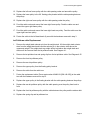
Safety guidelines you should know and follow include:
•
Visually check all cables and pulleys before beginning service or maintenance operations. If
the unit is not completely assembled or is damaged in any way, exercise extreme caution
while operating and checking the equipment.
•
Do not rock the unit. Do not stand or climb on the equipment.
•
Do not use accessory attachments that are not recommended by the manufacturer-such
attachments might cause injuries.
Required Tools and Equipment
The following list is a summary of the tools and supplies required when you service the
equipment.
Tools
Open end or combination wrench set
Socket wrench set
Allen wrench set
Rubber mallet
Supplies
Teflon anti-seize lubricant (McMaster-Carr 1404K12)
Pure mineral oil (no additives)
General Information
Many of the products listed in the service manual were manufactured in several versions.
Therefore, cable listings may show more than one part number for a particular cable
replacement. The cables will be listed chronologically with the newest version first. Where
appropriate, cable part numbers will be shown with both Precor and Pacific Fitness part
numbers. The Pacific Fitness part numbers will appear in brackets, e.g. 40665-101 [KU25-96250]. Either part number may appear on the cable. Always reference the part number stamped
on the cable to ensure the correct cable is available for replacement.
For the latest exploded view, part number and part pricing information, visit the Precor dealer
website at “www.precor.com/Dealer”.
Page 2
Consumer Strength Equipment
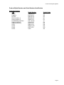
Product Model Number and Serial Number Identification
Consumer Product
Type
Malibu
Catalina
Del Mar
Zuma (version 1)
Zuma (version 2)
Freestanding leg Press
Solana (version 1)
Solana (version 2)
S3.21
S3.25
S3.45
S3.55
Model Number
MLB1-W-CS
KAT-W-CS
DM3-W-CS,
ZMA-W-CS
ZMA-G-CS
LPF1-W-CS
SOL-W-CS
SOL-G-CS
DM3-G-CS
MLB1-G-CS
KAT-G-CS
S355
Serial # Code
9F
9G
9H
9J
EY
J3
5Y
DP
DK
DH
DG
SA
Page 3
Consumer Strength Equipment
Section Two - Preventive Maintenance
Preventive maintenance measures are either scheduled or unscheduled. Scheduled preventive
maintenance activities are included here so that you are aware of preventive measures
performed on a regular basis.
Regular Preventive Maintenance (Owner)
Cleanliness of the equipment and its operating environment will keep maintenance problems and
service calls to a minimum. Precor recommends that you perform the following preventive
maintenance schedule.
At the End of Each Day
Wipe down the upholstery and handle grips with a damp cloth.
Every Week
Wipe the surface of the frame members and covers with a slightly-damp sponge or soft cloth. Dry
with a clean towel.
Semi-Annual
Remove tension from the cables in the unit as described in Procedure 4.1, step 2 and carefully
inspect each cable in the unit. Inspect the entire length of each cable for fraying or excessive
wear. Whenever possible slide the cable connector away from the cable end and inspect the
cable end for fraying or excessive wear. Replace any cable that exhibits fraying or excessive
wear.
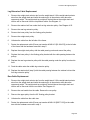
On-Site Preventive Maintenance (Service Technician)
Perform the following preventive maintenance tasks each time you are called to service the
equipment.
Examine the cables and pulleys for signs of wear or deterioration and replace if necessary.
Examine the upholstery and foam rollers for wear, cracks or other signs of deterioration and
replace if necessary.
Check the weight guide rods for lubrication. If necessary, apply a coat of teflon anti-seize
lubricant to the entire length of the weight guide rods.
Check pivot points to ensure that they rotate smoothly and freely. If necessary disassemble the
pivot point and lubricate the oilite bushing(s) with mineral oil
Page 4
Consumer Strength Equipment
Section Three - Checking Operation
This section provides you with a quick method of checking operation. Check operation at the end
of most maintenance procedures.
Procedure
1.
Remove all covers and visually inspect the entire length of all cables for wear or
deterioration. Visually check the connectors on each end of the cables to ensure that the
connectors are firmly fastened to the cables.
2.
Use each station (if unit is multi-station) at several weight settings. Ensure that each station
operates freely and smoothly.
3.
If the operation is rough or binding:
a.
Check the weight guide rod lubrication, if necessary lubricate the entire length of the
weight guide rods with teflon anti-seize lubricant.
b.
Disconnect one end of the cable and inspect the cable surface for worn or frayed areas.
Replace the cable if necessary. Refer to Section Four for cable replacement
procedures. Refer to Section Five for adjustment procedures (if required).
c.
Check pulley(s) to ensure that they rotate smoothly and freely. Replace if necessary.
d.
Check pivot points to ensure that they rotate smoothly and freely. If necessary
disassemble the pivot point and lubricate the oilite bushing(s) with mineral oil.
Page 5
Consumer Strength Equipment
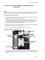
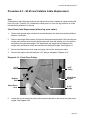
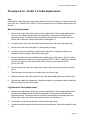
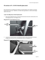
Procedure 4.1 - S3.21 and Del Mar Cable Replacement
Note:
All directions in the following procedures are referenced from the viewpoint of a person facing the
front of the unit. Therefore, on a Del Mar the weight stack is on the left hand side and the leg
extension is in front.
Main Cable Replacement (without leg press option)
1.
Remove the optional weight stack shroud, if furnished.
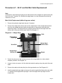
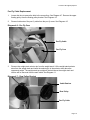
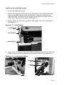
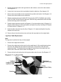
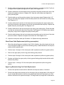
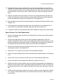
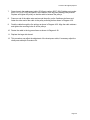
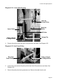
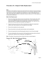
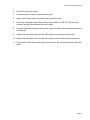
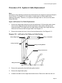
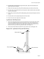
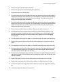
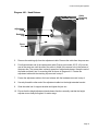
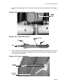
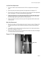
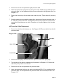
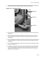
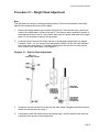
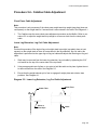
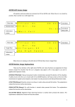
2.
Remove the weight stack selector pin from the weight stack. Lift the weight stack selector
stem from the weight stack and insert the selector pin in the selector stem above the
uppermost weight. The weight stack top weight will be held above the weight stack and
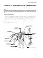
tension will be removed from the main cable. See Diagram 4.1.
Diagram 4.1 - Weight Stack
Cable
Weight Stack
Top Weight
Guide Rod
Weight Stack
Selector Pin
Weight Stack
Selector Stem
Weight
3.
Fasten the swing arm to the selector cam arm with a large cable tie or other suitable
temporary fastener. See Diagram 4.3.
4.
Loosen, but do not remove, all of the bolts that retain the pulleys along the path of the main
cable.
5.
Remove the retainer bolt and pulley from the leg extension arm. See Diagram 4.8.
6.
Hold the weight stack top weight and remove the socket cap bolt that fastens the main cable
“U” bracket to the weight stack top weight. Lower the weight stack top weight onto the
weight stack.
Page 6
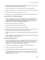
Consumer Strength Equipment
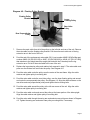
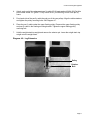
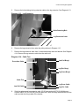
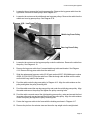
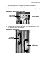
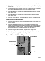
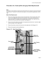
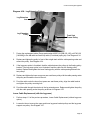
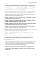
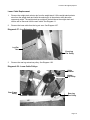
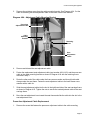
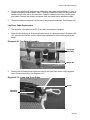
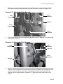
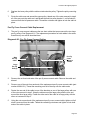
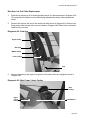
Diagram 4.2 - Floating Pulley Bracket
Floating Pulley
Bracket
Lower
Floating Pulley
Rear Inline
Pulley
Rear Perpendicular
Pulley
7.
Remove the main cable from all of the pulleys on the left side and rear of the unit. Remove
the main cable from the floating pulley bracket. Pull the entire main cable out of the leg
extension arm in the front of the unit.
8.
Feed the end of the replacement main cable (S3.21 part number 40485-102)(Del Mar part
number 40485-101 [BU-322-125] or 40627-101 [BU-293-625] or 40640-101 [CK-167-000])
that attaches to the weight stack top weight (the end with the U-bracket) into the leg
extension arm. Pull all of the main cable to the rear of the unit.
9.
Replace the leg extension pulley and retainer bolt removed in step 5. The main cable must
pass over the retainer bolt and under the pulley. See Diagram 4.8.
10. Feed the main cable under the pulley near the center of the seat frame. Align the cable
retainer and tighten pulley’s mounting bolt.
11. Feed the main cable under the rear inline pulley, over the lower floating pulley and around
and under the rear perpendicular pulley. See Diagram 4.2. Align the cable retainers on the
rear inline and rear perpendicular pulleys and tighten their mounting bolts.
12. Feed the main cable around the pulley at the left rear corner of the unit. Align the cable
retainer and tighten pulley’s mounting bolt.
13. Feed the main cable under and around the pulley at the lower portion of the side upright.
Align the cable retainer and tighten pulley’s mounting bolt.
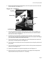
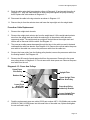
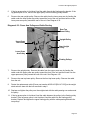
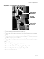
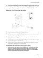
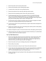
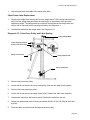
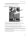
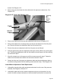
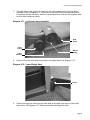
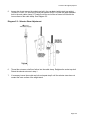
14. Feed the main cable through the swing arm and selector cam pulleys as shown in Diagram
4.3. Tighten the swing arm and sector cam pulley mounting bolts, if necessary.
Page 7
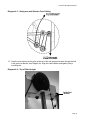
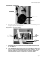
Consumer Strength Equipment
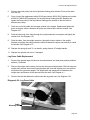
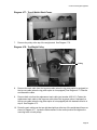
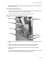
Diagram 4.3 - Swing arm and Selector Cam Cabling
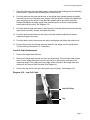
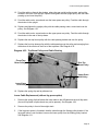
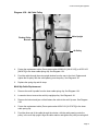
15. Feed the main cable over the pulley at the top of the side upright and down through the hole
in the guide rod bracket. See Diagram 4.4. Align the cable retainer and tighten pulley’s
mounting bolt.
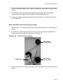
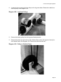
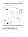
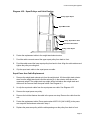
Diagram 4.4 - Top of Side Upright
Guide Rod
Bracket
Page 8
Consumer Strength Equipment
16. Slide the U bracket (with the bracket’s set screw holes on the left, outside) on the main cable
onto the weight stack selector stem. Replace and tighten the weight stack top weight socket
cap bolt.
17. Verify that all pulley mounting bolts are tight and that the cable retainers are properly
aligned. Remove the cable tie or other fastener that was attached in step 3.
18. If necessary, adjust the weight stack alignment per Procedure 5.1 and main cable tension
per Procedure 5.2.
Main Cable Replacement (with leg press option)
1.
Perform steps 1-12 of the previous procedure, Main Cable Replacement (without leg press
option).
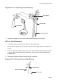
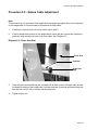
2.
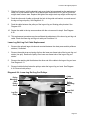
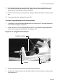
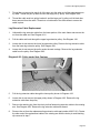
Feed the main cable through the upper and lower pulleys on the leg press plate and the
pulley on the leg press support arm as shown in Diagram 4.5.
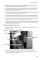
Diagram 4.5 - Leg Press Pulley Cabling
Upper Pulley
Leg Press Plate
Support Arm
3.
Lower Pulley
Leg Press Plate
Perform steps 14-18 of the previous procedure, Main Cable Replacement (without leg press
option).
Page 9
Consumer Strength Equipment
Pec Fly Cable Replacement
1.
Loosen but do not remove the bolts in the rear pulleys. See Diagram 4.7. Remove the upper
floating pulley from the floating pulley bracket. See Diagram 4.2.
2.
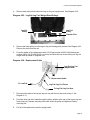
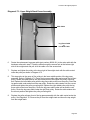
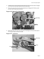
Remove both ends of the pec fly cable from the pec fly cams. See Diagram 4.5.
Diagram 4.6 - Pec Fly Cam
Pec Fly Cable
Pec Fly Cam
3.
Remove the weight stack selector pin from the weight stack. Lift the weight stack selector
stem from the weight stack and insert the selector pin in the selector stem above the
uppermost weight. The weight stack top weight will be held above the weight stack and
tension will be removed from the main cable. See Diagram 4.1.
Diagram 4.7 - Rear Pulley Bracket
Cable Retainer
Rear Pulley
Pec Fly Cable
Page 10
Consumer Strength Equipment
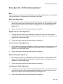
4.
Attach each end of the replacement pec fly cable (S3.21 part number 40484-102)(Del Mar
part number 40484-101 ([WW-73-750] or 40479-101 [GG-80-500]) to one of the pec fly
cams.
5.
Feed each side of the pec fly cable through one of the rear pulleys. Align the cable retainers
and tighten the pulley mounting bolts. See Diagram 4.7.
6.
Place the pec fly cable under the upper floating pulley. Remount the upper floating pulley
and pec fly cable in the floating mounting bracket. Tighten the upper floating pulley
mounting bolt.
7.
Hold the weight stack top weight and remove the selector pin. Lower the weight stack top
weight onto the weight stack.
Diagram 4.8 - Leg Extension
Pulley
Retainer
Bolt
Page 11
Consumer Strength Equipment
Procedure 4.2 - S3.25 and Malibu Cable Replacement
Procedures
Note:
All directions in the following procedures are referenced from the viewpoint of a person facing the
front of the unit. Therefore, the weight stack is in the left rear and the press arm is in front.
Lat Pulldown Cable Replacement
1.
Remove the weight stack shrouds. Remove the lat pulldown bar and the clip that fastened
the lat pulldown bar to it’s cable. See Diagram 4.10.
2.
Remove the weight stack selector pin from the weight stack. Lift the weight stack selector
stem from the weight stack and insert the selector pin in the selector stem above the
uppermost weight. The weight stack top weight will be held above the weight stack and
tension will be removed from the cable. See Diagram 4.1.
3.
Support the top weight and remove the bolt the fastens the lat pulldown cable to the selector
stem. Lower the top weight onto the weight stack.
4.
Remove upper pulley from the floating pulley bracket. See Diagram 4.9
Diagram 4.9 - Floating Pulley Bracket
Top Beam
Guide Rod
Bracket
Top Beam
Window
Upper Pulley
Floating Pulley
Bracket
Lower Pulley
5.
Pull the cable upward through the hole in the guide rod bracket. Remove the cable from the
pulleys above the guide rod bracket. Pull the cable upward through the window in the top
beam.
Page 12
Consumer Strength Equipment
6.
Remove the retainer bolt from the lat pulldown end of the top beam and remove the cable
from the top beam. See Diagram 4.10.
Diagram 4.10 - Lat Pulldown
Top Beam
Retainer Bolt
Window
Clip
Lat Pulldown Bar
7.
Fasten the replacement lat pulldown cable (S3.25 part number 44370-101)(Malibu part
number 43626-101 [KU-120-625]) to the weight stack selector stem. Raise the selector
stem and pin as shown in Diagram 4.1.
8.
Feed the loose end of the cable up through the guide rod bracket, over the two pulleys
above the guide rod bracket and upward through the window in the top beam. See Diagram
4.9. Leave a loop of cable below the top beam window.
9.
Place the cable loop, step 8, into the upper portion of the floating bracket and replace the
upper pulley in the floating bracket. See Diagram 4.9.
10. Pass the cable over the pulley at the rear of the top beam and over the pulley at the front of
the top beam.
11. Pass the cable downward through the window in the front of the top beam and replace the
retainer bolt. See Diagram 4.10.
12. Replace the lat pulldown bar clip and the lat pulldown bar. See Diagram 4.10.
13. Remove the pin from the selector stem and lower the top weight onto the weight stack.
Adjust the selector stem per Procedure 5.1, if necessary.
Page 13
Consumer Strength Equipment
Leg Extension Cable Replacement
1.
Remove the weight stack shrouds.
2.
Remove the weight stack selector pin from the weight stack. Lift the weight stack selector
stem from the weight stack and insert the selector pin in the selector stem above the
uppermost weight. The weight stack top weight will be held above the weight stack and
tension will be removed from the cable. See Diagram 4.1.
3.
Remove the bolt that retains the leg extension cable retainer, remove the cable retainer.
See Diagram 4.11.
Diagram 4.11 - Cable Retainer
Leg Extension
Cable
Low Pull Cable
Cable Retainer
4.
Loosen but do not remove the leg extension pulley below the leg extension seat and the leg
extension pulley in the group of three pulleys at the base of the unit. See Diagram 4.12.
Diagram 4.12 - Leg Extension Pulleys
Leg Press
Pulley
Low Pull
Pulley
Leg Extension Pulley
Leg Extension Pulley
Page 14
Consumer Strength Equipment
5.
Remove the bolt retaining the leg extension cable to the leg extension. See Diagram 4.13.
Diagram 4.13 - Leg Extension
Cable Retaining Bolt
Leg Extension Cable
6.
Remove the leg extension from under the pulleys shown in Diagram 4.12.
7.
Remove the leg extension cable from it’s associated bungi cable and bracket. See Diagram
4.14. Remove the leg extension cable from the cable tree.
Diagram 4.14 - Cable Tree
Press Arm Cable
Low Pull Bungi
Leg Ext. Bungi
Leg Press Bungi
Cable Tree
Leg Press Cable
Low Pull Cable
8.
Leg Ext. Cable
Slide the replacement leg extension cable (S3.25 part number 44376-101)(Malibu part
number 40422-101 [IN-119-500]) into the cable tree. Slide the bungi cable bracket onto the
cable and bolt the bungi cable to the bracket.
Page 15
Consumer Strength Equipment
9.
Feed the cable under both leg extension pulleys in Diagram 4.12 and around the pulley in
Diagram 4.11. Align the cable retainers on both pulleys and tighten the pulley mounting
bolts. Replace the cable retainer in Diagram 4.11.
10. Reconnect the cable to the leg extension as shown in Diagram 4.13.
11. Remove the pin from the selector stem and lower the top weight onto the weight stack.
Press Arm Cable Replacement
1.
Remove the weight stack shrouds.
2.
Remove the weight stack selector pin from the weight stack. Lift the weight stack selector
stem from the weight stack and insert the selector pin in the selector stem above the
uppermost weight. The weight stack top weight will be held above the weight stack and
tension will be removed from the cable. See Diagram 4.1.
3.
The press arm cable passes downward through the tube in the cable tree and is fastened
underneath the cable tree bracket. See Diagram 4.14. Remove the nut that retains the press
arm cable to the cable tree, remove the press arm cable from the cable tree.
4.
Remove the lower pulley from the floating pulley bracket, remove the press arm cable from
the floating bracket. See Diagram 4.9.
5.
Remove the AB crunch clip and retainer bolt from the press arm. Remove the four press
arm pulleys shown in Diagram 4.15. Do not remove the lower press arm. Remove the press
arm cable from the unit.
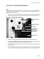
Diagram 4.15 - Press Arm Pulleys
Upper Press
Arm Pulley
Upright Tube
Retainer Bolt
Clip
Lower Press
Arm Pulley
Do not remove
Upper Upright Tube
Press Arm Pulley
Press Arm Pulley
Inside Adj. Bracket
Lower Upright Tube
Press Arm Pulley
6.
Feed the replacement press arm cable (S3.25 part number 44371-101)(Malibu part number
43628-101 [KM-116-500]) down into the center tube of the cable tree, replace and tighten
the nut removed in step 3.
Page 16
Consumer Strength Equipment
7.
Place the cable over the lower floating pulley, replace the lower floating pulley in the floating
pulley bracket. Tighten the lower floating pulley mounting bolt.
8.
Feed the cable into the lower rear window in the upright tube, upward through the upright
tube and forward out of the upper front window of the upright tube. Replace and tighten the
lower upright press arm pulley so that the cable passes around and under the pulley.
Replace and tighten the upper upright tube press arm pulley so that the cable passes
around and over the pulley. See Diagram 4.15.
9.
Feed the cable through the window in the press arm. Pass the cable around and under the
upper press arm pulley, replace and tighten the pulley.
10. Feed the cable around and under the pulley inside the inside the adjustment bracket,
replace and tighten the pulley.
11. Feed the cable over the lower press arm pulley and replace and tighten the retainer bolt.
12. Remove the pin from the selector stem and lower the top weight onto the weight stack.
Tension cable per Procedure 5.3, if necessary.
Low Pull Cable Replacement
1.
Remove the weight stack shrouds.
2.
Remove the weight stack selector pin from the weight stack. Lift the weight stack selector
stem from the weight stack and insert the selector pin in the selector stem above the
uppermost weight. The weight stack top weight will be held above the weight stack and
tension will be removed from the cable. See Diagram 4.1.
3.
Remove the clip from the low pull cable and the low pull pulley. See Diagram 4.16
Diagram 4.16 - Low Pull Cable
Low Pull Pulley
Clip
Page 17
Consumer Strength Equipment
4.
Remove the bolt that retains the leg extension cable retainer, remove the cable retainer.
See Diagram 4.11.
5.
Loosen but do not remove the low pull pulley below the cable tree. See diagram 4.12.
6.
Remove the low pull cable from it’s associated bungi cable and bracket. See Diagram 4.14.
Remove the low pull cable from the cable tree.
7.
Slide the replacement low pull cable (S3.25 part number 44375-101)(Malibu part number
43627-101 [KN-139-250]) into the cable tree. Slide the bungi cable bracket onto the cable
and bolt the bungi cable to the bracket.
8.
Feed the cable under the low pulley in Diagram 4.12 and around the pulley in Diagram 4.11.
Align the cable retainer on the low pull pulley and tighten the pulley mounting bolt. Replace
the cable retainer in Diagram 4.11.
9.
Feed the cable under the low pull pulley in Diagram 4.16, replace and tighten the pulley.
Replace the low pull clip.
10. Remove the pin from the selector stem and lower the top weight onto the weight stack.
Leg Press Cable Replacement
Note:
The leg press is optional and may not be equipped.
1.
Remove the weight stack shrouds.
1.
Remove the weight stack selector pin from the weight stack. Lift the weight stack selector
stem from the weight stack and insert the selector pin in the selector stem above the
uppermost weight. The weight stack top weight will be held above the weight stack and
tension will be removed from the cable. See Diagram 4.1.
2.
Remove the bolt and bushing from the leg press cable under the seat. See Diagram 4.17
Diagram 4.17 - Leg Press Cable
Left Hand
Leg Press Pulley
Right Hand
Leg Press Pulley
Leg Press Cable
Front
Leg Press Pulley
Bushing
Page 18
Consumer Strength Equipment
3.
Loosen but do not remove the front leg press pulley. Remove the leg press cable from the
right hand, front and left hand pulleys. See Diagram 4.17.
4.
Loosen but do not remove the middle and rear leg press pulleys. Remove the cable from the
middle and rear leg press pulleys. See Diagram 4.18.
Diagram 4.18 - Leg Press Pulleys
Middle Leg Press Pulley
Rear Leg Press Pulley
5.
Loosen but do not remove the leg press pulley under the cable tree. Remove the cable from
the pulley. See Diagram 4.12.
6.
Remove the leg press cable from it’s associated bungi cable and bracket. See Diagram
4.14. Remove the leg press cable from the cable tree.
7.
Slide the replacement leg press cable (S3.25 part number 40537-102)(Mailbu part number
40538-101 [IN-120-875]) into the cable tree. Slide the bungi cable bracket onto the cable
and bolt the bungi cable to the bracket.
8.
Feed the cable under the leg press pulley in Diagram 4.12. Align the cable retainer on the
pulley and tighten the pulley mounting bolt.
9.
Feed the cable around the rear leg press pulley and under the middle leg press pulley. Align
the cable retainers on the pulleys and tighten the pulley mounting bolts.
10. Feed the cable over and around the right hand leg press pulley, under and around the front
leg press pulley and over and around the left hand leg press pulley. Align the cable retainer
on the front pulley and tighten the pulley mounting bolt.
11. Fasten the leg press cable to the frame with the bushing as shown in Diagram 4.17.
12. Remove the pin from the selector stem and lower the top weight onto the weight stack.
Page 19
Consumer Strength Equipment
Procedure 4.3 - S3.45 and Catalina Cable Replacement
Note:
All directions in the following procedures are referenced from the viewpoint of a person facing the
front of the unit. Therefore, on a Catalina the chest press is in front, the leg extension is on the
left and the lat pulldown is in the rear
.
Chest Press Cable Replacement (without leg press option)
1.
Remove the optional large side shroud mounted between the chest press and lat pulldown
stations, if furnished.
2.
Remove the weight stack selector pin from the chest press weight stack. Lift the chest press
weight stack selector stem from the weight stack and insert the selector pin in the selector
stem above the uppermost weight. The weight stack top weight will be held above the
weight stack and tension will be removed from the chest press cable. See Diagram 4.1.
3.
Remove the abdominal crunch strap and spring clip from the chest press cable.
4.
Remove the retainer bolt and the three 4-1/2” pulleys indicated in Diagram 4.19.
Diagram 4.19 - Chest Press Pulleys
4-1/2”
Pulley
Retainer
Bolt
Chest Press
Arm
5.
4-1/2”
Pulley
Chest Press
Upright
4-1/2”
Pulley
Loosen but do not remove the pulley from the pulley bracket on the rear of the chest press
upright. See Diagram 4.20.
Page 20
Consumer Strength Equipment
Diagram 4.20 - Pulley Bracket
Cable Bracket
Cable Retainer
Pulley
6.
Remove the 6” pulley chest press pulley from the upper frame. It is located directly over the
chest press weight stack. See Diagram 4.21.
Diagram 4.21 - Upper Frame Pulleys
6” Chest
Press Pulley
6” Lat
Pulldown
Pulley
4-1/2” Leg
Ext./Leg Curl
Pulley
7.
Disconnect the cable from the weight stack selector stem, and remove the cable from the
unit. See Diagram 4.1.
8.
Fasten the replacement cable (S3.45 part number 43621-102)(Catalina part number 43623101 [KU-173-750]) to the weight stack selector stem as shown in Diagram 4.1. Slide the U
bracket (with the bracket’s set screw holes outward) on the cable onto the weight stack
selector stem. Replace and tighten the weight stack top weight socket cap bolt.
Page 21
Consumer Strength Equipment
9.
Feed the cable up through the slot in the guide rod bracket, over and around the 6” pulley in
the upper frame. Replace and tighten the 6” pulley. See Diagram 4.21.
10. Feed the cable down and around the pulley mounted on the pulley bracket at the rear of the
chest press upright as shown in Diagram 4.20. Align the cable retainer and tighten the
pulley mounting bolt.
11. Feed the cable up and through the window in the chest press upright. Replace the 4-1/2”
pulley in the chest press upright so that the cable passes over and to the front of the pulley.
See Diagram 4.19.
12. Loop the cable into the window in the chest press arm and replace the upper chest press
arm pulley so that the cable passes over the top, around and behind the pulley. Replace and
tighten the pulley mounting bolt. See Diagram 4.19.
13. Feed the cable back to the rear chest press arm pulley (cam adjust pulley). Route the cable
over the top, and around to the front of the pulley. See Diagram 4.19. Replace cam adjuster
and pulley, snug but do not tighten the pulley mounting bolt.
14. Feed the cable between the two front chest press arm pulleys and out the front of the chest
press arm window. Replace and tighten the retainer bolt. See Diagram 4.19.
15. Adjust the chest press cable per Procedure 5.4. Replace the large side shroud.
Chest Press Cable Replacement (with leg press option)
1.
When the optional leg press is added to the S3.45 or Catalina, the pulley bracket at the rear
of the chest press upright is removed and a floating pulley is added between the chest press
cable and the leg press cable.
2.
Perform steps 1 through 4 of the chest press cable replacement (without leg press option).
3.
Remove the upper pulley from the leg press floating pulley bracket.
4.
Perform steps 6 through 9 of the chest press cable replacement (without leg press option).
5.
Replace and tighten the upper pulley in the leg press floating pulley bracket with the cable
between the pulleys.
6.
Perform steps 11 through 15 of the chest press cable replacement (without leg press
option).
Upper Leg Extension/Leg Curl Cable Replacement
1.
Remove the optional side shroud from behind the chest press station, if furnished.
2.
Remove the weight stack selector pin from the leg ext./leg curl weight stack. Lift the leg ext./
leg curl weight stack selector stem from the weight stack and insert the selector pin in the
selector stem above the uppermost weight. The weight stack top weight will be held above
Page 22
Consumer Strength Equipment
the weight stack and tension will be removed from the cable. See Diagram 4.1.
3.
Remove the cable from the leg ext/leg curl weight stack selector stem.
4.
Remove the nut retaining the other end of cable to the top cross member. See Diagram 4.22
Diagram 4.22 - Upper Leg Ext./Leg Curl Cable
Upper Leg Ext.
Leg Curl Cable
Top Cross Member
5.
Loosen but do not remove the leg ext./leg curl pulley. See Diagram 4.21.
6.
Remove the cable from the leg ext./leg curl pulley, feed the cable through the leg ext./leg
curl floating pulley bracket. See Diagram 4.23
Diagram 4.23 - Floating Pulleys
Lat Pulldown
Floating Pulleys
Leg Ext./Leg Curl
Floating Pulleys
Page 23
Consumer Strength Equipment
7.
Slide the U bracket (with the bracket’s set screw holes facing outward) on the replacement
cable (S3.45 part number 40535-102)(Catalina part number 40535-101 [MU-87]) onto the
weight stack selector stem. Replace and tighten the weight stack top weight socket cap bolt.
8.
Feed the other end of cable up through the hole in the guide rod bracket, over and around
the leg ext./leg curl pulley. See Diagram 4.21.
9.
Feed the cable between the pulleys of the leg ext./leg curl floating pulley bracket. See
Diagram 4.23.
10. Fasten the cable to the top cross member with the nut removed in step 4. See Diagram
4.22.
11. This replacement procedure may have affected the adjustment of the lower leg ext./leg curl
cable. Check the lower leg ext./leg curl cable per Procedure 5.4.
Lower Leg Ext./Leg Curl Cable Replacement
1.
Remove the optional large side shroud mounted between the chest press and lat pulldown
stations, if furnished.
1.
Remove the ankle strap and spring clip from the lower rear frame tube of the leg ext./leg curl
station (low pull). Remove the pulley from lower rear frame tube of the leg ext./leg curl
station.
2.
Remove the retaining bolt that fastens the other end of the cable to the leg ext./leg curl arm.
See Diagram 4.13.
3.
Remove both bolts that fasten the pulleys under the leg ext./leg curl seat. See Diagram
4.24. Remove both pulleys.
Diagram 4.24 - Lower Leg Ext./Leg Curl Pulleys
Pulley
Mounting
Bolt
Pulley
Cover
Leg Ext.
Pulley
Cable
Retainer
Pulley
Mounting
Bolt
Low Pull
Pulley
Page 24
Consumer Strength Equipment
4.
Remove both pulleys from behind the leg ext./leg curl weight stack. See Diagram 4.25.
Diagram 4.25 - Leg Ext./Leg Curl Weight Stack Pulleys
Leg Ext.
Pulley
Low Pull
Pulley
Retainer Pins
5.
Remove the lower pulley from the leg ext./leg curl floating pulley bracket. See Diagram 4.23.
Remove the cable from the unit.
6.
Form the middle of the replacement cable (S3.45 part number 43622-102)(Catalina part
number 43622-101 [IK-245-3125]) in to a loop and slide the loop under the leg ext./leg curl
weight stack as shown in Diagram 4.25.
Diagram 4.26 - Replacement Cable
Leg Ext./Leg Curl
Weight Stack
Replacement Cable
To Low Pull
Leg Ext./Leg Curl Frame
To Leg Ext./Leg Curl Arm
7.
Reconnect the cable to the leg ext./leg curl arm with the bolt removed in step 2. See
Diagram 4.13.
8.
Feed the other end of the cable through the pulley window at the rear of the leg ext./leg curl
frame (low pull). Replace the pulley with cable under the pulley and tighten the pulley
mounting bolt.
9.
Pull all of the cable slack under the weight stack.
Page 25
Consumer Strength Equipment
10. Assembly the leg ext. pulley, cable retainer, low pull pulley and pulley cover as shown in
Diagram 4.24 with the cable from the leg ext./leg curl arm around and to the right of the leg
ext. pulley and the cable from the low pull around and to the right of the low pull pulley. Align
the cable retainer on the leg ext. pulley. Tighten the leg ext. and low pull pulley mounting
bolts.
11. Replace and tighten both of the pulleys at the rear of the weight stack with the cable from
the leg ext./leg curl arm between the leg ext. pulley and it’s retainer pin and the cable from
the low pull between the pulley and it’s retainer pin. See Diagram 4.25.
12. Place the cable loop around the lower floating pulley and replace and tighten the pulley. See
Diagram 4.23.
13. If the weight stack top weight (cap plate) does not rest squarely on the weight stack or if
excess slack is encountered in the cable, adjust the cable per Procedure 5.4.
14. If equipped, replace the optional large side shroud. Replace the spring clip and ankle strap.
Upper Preacher Curl Cable Replacement
1.
Remove the optional large side shroud mounted between the chest press and lat pulldown
stations, if furnished.
2.
Remove the weight stack selector pin from the lat pulldown weight stack. Lift the lat
pulldown weight stack selector stem from the weight stack and insert the selector pin in the
selector stem above the uppermost weight. The weight stack top weight will be held above
the weight stack and tension will be removed from the cable. See Diagram 4.1.
3.
Remove the lat pulldown bar and spring clip. Remove the 4-1/2” pulley from the end of the
lat pulldown top beam. See Diagram 4.10.
4.
Remove the 3-1/2” pulley from the center of the lat pulldown top beam.
5.
Remove the upper floating pulley from the lat pulldown floating pulley bracket. See Diagram
4.23.
6.
Remove the 6” pulley from the top of the frame over the lat pulldown weight stack.
7.
Remove the cable from the weight stack. Remove the cable from the unit.
8.
Slide the U bracket (with the bracket’s set screw holes facing outward) on the replacement
cable (S3.45 part number 43621-102)(Catalina part number 43621-101 [KU-133-375]) onto
the weight stack selector stem. Replace and tighten the weight stack top weight socket cap
bolt
9.
Feed the cable up through the window in the top of the frame over the weight stack. Replace
the 6” pulley so that the cable feeds over around and down the pulley. Tighten the pulley
mounting bolt.
Page 26
Consumer Strength Equipment
10. Replace the upper floating pulley with the cable between the two pulleys. Tighten the pulley
mounting bolt.
11. Feed the end of the cable into the center window of the lat pulldown top beam and push into
the top until the cable emerges from the window in the end of the top beam.
12. Replace and tighten the 3-1/2” pulley in the center window of the top beam with the cable
routed over the pulley.
13. Replace and tighten the 4-1/2” pulley in the end window of the top beam with the cable
routed over the pulley.
14. Replace the optional side cover, if equipped. Replace the spring clip and lat pulldown bar.
Lower Preacher Curl Cable Replacement
1.
Remove the optional side cover from the lat pulldown side of the unit and the optional large
shroud, if furnished.
2.
Remove the weight stack selector pin from the lat pulldown weight stack. Lift the lat
pulldown weight stack selector stem from the weight stack and insert the selector pin in the
selector stem above the uppermost weight. The weight stack top weight will be held above
the weight stack and tension will be removed from the cable. See Diagram 4.1.
3.
Remove the spring clip and “V” row handle, spring clip and 18” straight handle.
4.
Remove the two pulleys in the upright and the retainer bolt in the upright extension. Do not
remove the pulley in the upright extension. See Diagram 4.27.
Diagram 4.27 - Lower Lat Pulldown Pulleys
Upper Window
Upright Extension
Retainer Bolt
Upright
Lower Window
Page 27
Consumer Strength Equipment
5.
Remove the lower pulley from the lat pulldown floating pulley bracket. Remove the cable
from the unit.
6.
Form a loop of the replacement cable (S3.45 part number 43620-102)(Catalina part number
43620-101 [KK-88-250]) and place it in the lat pulldown floating bracket. Replace and
tighten the lower pulley in the lat pulldown floating pulley bracket so that the cable is
between the pulleys.
7.
Feed one end of the cable into the upper window in the upright. Replace and tighten the
pulley so that the cable is between the pulley and retainer pin inside the window. See
Diagram 4.27.
8.
Feed the other end of the cable through the upright extension and replace and tighten the
retainer bolt. See Diagram 4.27.
9.
Feed the cable, from the upright extension, through the lower window in the upright.
Replace and tighten the pulley so that the cable is between the pulley and retainer pin inside
the window. See Diagram 4.27
10. Replace the spring clip and “V” row handle, spring clip and 18” straight handle.
11. Replace the optional side cover, if equipped.
Leg Press Cable Replacement
1.
Remove the optional large side shroud mounted between the chest press and lat pulldown
stations, if furnished.
2.
Remove the weight stack selector pin from the chest press weight stack. Lift the chest press
weight stack selector stem from the weight stack and insert the selector pin in the selector
stem above the uppermost weight. The weight stack top weight will be held above the
weight stack and tension will be removed from the cable. See Diagram 4.1.
3.
Remove the bolt that fastens the cable under the leg press seat. See Diagram 4.28
Diagram 4.28 - Leg Press Cable
Cable
Mounting Bolt
Page 28
Consumer Strength Equipment
4.
Loosen but do not remove the five pulleys on the leg press frame. Remove the cable from
the five pulleys. See Diagram 4.29.
Diagram 4.29 - Leg Press Pulleys
5.
Remove the bottom pulley from the leg press floating bracket.
6.
Remove the pulley from the bottom of the Catalina frame, where the leg press frame joins
the Catalina frame. See Diagram 4.30. Remove the cable from the unit.
Diagram 4.30 - Pulley on Catalina Frame.
Page 29
Consumer Strength Equipment
7.
Form a loop in the replacement cable (S3.45 part number 40537-102)(Catalina part number
40537-101 [II-147-625]) And place it in the bottom of the leg press floating pulley bracket.
Replace and tighten the pulley so that the cable is between the pulleys.
8.
Pass one end of the cable under and around the pulley on the Catalina main frame and
fasten the other end of the cable to the pulley mounting bolt as shown in Diagram 4.30.
9.
Feed the cable through the five pulleys as shown in Diagram 4.29. Align the cable retainers
and tighten the mounting bolts on all five pulleys.
10. Fasten the cable to the leg press frame as shown in Diagram 4.28.
11. Replace the large side shroud.
12. This procedure may affect the adjustment of the chest press cable, if necessary adjust the
chest press cable per Procedure 5.4.
Page 30
Consumer Strength Equipment
Procedure 4.4 - Zuma (white and gray) Cable Replacement
Note:
All directions in the following procedures are referenced from the viewpoint of a person facing the
front of the unit. Therefore, on a Zuma the chest press is in front and the weight stack is on the
right.
Main Cable Replacement
1.
Remove the weight stack selector pin from the weight stack. Lift the weight stack selector
stem from the weight stack and insert the selector pin in the selector stem above the
uppermost weight. The weight stack top weight will be held above the weight stack and
tension will be removed from the main cable. See Diagram 4.1.
2.
Remove the bolt that fastens the cable to the weight stack selector stem. Lower the weight
stack top weight onto the weight stack.
3.
Remove the pulley mounted in the frame over the weight stack. See Diagram 4.31.
4.
Remove the spring clip and lat pulldown bar.
Diagram 4.31 - Upper Frame Pulley
Pulley over
Weight Stack
Rear Upright
Pulley
Lower Floating
Pulley Mounting
when Leg Press
is not Furnished
Upper Floating
Pulley
Lower Floating
Pulley (Leg Press
Furnished)
Page 31
Consumer Strength Equipment
5.
If the leg press option is furnished, feed the cable through the floating pulley bracket. If the
leg press option is not, remove the upper pulley from the floating pulley bracket.
6.
Remove the rear upright pulley. Remove the cable from the lower press arm by feeding the
cable under the lower press arm pulley toward the front of the unit and then back over the
lower press arm pulley toward the rear of the unit. See Diagram 4.32.
Diagram 4.32 - Press Arm Pulleys and Cable Routing
Rear Top
Beam Pulley
Upper Press
Arm Pulley
Upright Pulley
Rear Upright
Pulley
Lower Press
Arm Pulley
Floating Pulleys
7.
Remove the upright pulley. Remove the cable from the upper press arm by feeding the
cable under the upper press arm pulley toward the front of the unit and then back over the
upper press arm pulley toward the rear of the unit. See Diagram 4.32.
8.
Remove the rear top beam pulley. Remove the front top beam pulley. Remove the cable
from the unit.
9.
Fasten the replacement cable (Precor part number 40509-102 [BU-147-250]) to the weight
stack selector stem with the bolt removed in step 2.
10. Replace and tighten the pulley over the weight stack with the cable passing over and around
the pulley.
11. If the leg press option is furnished, feed the cable between the pulleys in the floating pulley
bracket. If the leg press option is not furnished, feed the cable into the floating pulley
bracket. Replace and tighten the upper floating pulley with the cable passing between the
two pulleys.
Page 32
Consumer Strength Equipment
12. Feed the cable up through the window, where the rear upright pulley mounts, and out the
window in the front of the upright. Replace and tighten the rear upright pulley with the cable
passing up and over the pulley.
13. Feed the cable under, around and over the lower press arm pulley. Feed the cable through
the window in the upright
14. Replace and tighten the upright pulley with the cable passing under, around and over the
pulley. See Diagram 4.32.
15. Feed the cable under, around and over the upper press arm pulley. Feed the cable through
the window in the rear of the top beam.
16. Replace the rear top beam pulley with the cable passing behind and over the pulley.
17. Replace the front top beam pulley with the cable passing over the pulley and emerging from
the bottom of the window in the front of the top beam. See Diagram 4.33.
Diagram 4.33 - Top Beam Pulleys and Cable Routing
Front Top
Beam Pulley
Rear Top
Beam Pulley
Upper Press
Arm Pulley
Lower Press
Arm Pulley
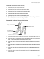
18. Replace the spring clip and lat pulldown bar.
Lower Cable Replacement (without leg press option)
1.
Remove the spring clip that fastens the lower cable to the AB cable and the multi hip cable
(the multi hip cable is optional and may not be present). See Diagram 4.34.
2.
Remove the pulley in front of the weight stack.
3.
If the leg press option is furnished, feed the cable through the floating pulley bracket. If the
leg press option is not furnished, remove the lower pulley from the floating pulley bracket.
See Diagram 4.31.
Page 33
Consumer Strength Equipment
Diagram 4.34 - Lower Cable Routing
Multi Hip
Upright Pulley
Lower Cable
Multi Hip
Cable
AB Cable
Pulley in Front
of Weight Stack
4.
Spring Clip
Remove the pulley at the lower rear of the press arm seat frame. See Diagram 4.35
Diagram 4.35 - Seat Frame Pulley
Rear Seat
Frame Pulley
Pulley in Front
of Weight Stack
5.
Loosen but do not remove the pulley at the lower front of the press arm seat frame. See
Diagram 4.35.
6.
Remove the pulley from the leg extension arm. Remove the cable from the unit.
Page 34
Consumer Strength Equipment
Diagram 4.36 - Leg Extension Pulleys
Leg Extension
Arm
Leg Extension
Pulley
Front Seat
Frame Pulley
7.
Fasten the replacement cable (Precor part number 40507-101 [BB-152-125] or 42760-102
[148-688]) to the AB cable and multi hip cable (if furnished) spring clip. See Diagram 4.34.
8.
Replace and tighten the pulley in front of the weight stack with the cable passing under and
around the pulley. See Diagram 4.34.
9.
If the leg press option is furnished, feed the cable between the pulleys in the floating pulley
bracket. If the leg press option is not furnished, feed the cable into the floating pulley
bracket. Replace and tighten the lower floating pulley with the cable passing between the
two pulleys.
10. Replace and tighten the lower rear press arm seat frame pulley with the cable passing under
the pulley and toward the front of the unit.
11. Feed the cable under the lower front press arm seat frame pulley, align the cable bracket
and tighten the pulley mounting bolt.
12. Feed the cable through the window in the leg extension arm. Replace and tighten the pulley
with the cable passing under the pulley as shown in Diagram 4.35.
Lower Cable Replacement (with the leg press)
1.
Perform steps 1-3 of the previous procedure, Lower Cable Replacement (without leg press
option).
2.
Loosen but do not remove the upper and lower leg press bracket pulleys and the leg press
support arm pulley. See Diagram 4.37.
Page 35
Consumer Strength Equipment
Diagram 4.37 - Leg Press Pulleys and Cable Routing
Upper Leg Press
Bracket Pulley
Leg Press
Support Arm
Pulley
Lower Leg Press
Bracket Pulley
3.
Remove the cable from the three pulleys in Diagram 4.37.
4.
Perform steps 4-8 of the previous procedure, Lower Cable Replacement (without leg press
option).
5.
Feed the cable around the three pulleys as shown in Diagram 4.37. Align the cable brackets
and tighten the three pulley mounting bolts.
6.
Perform steps 9-12 of the previous procedure, Lower Cable Replacement (without leg press
option).
Ab Cable Replacement
1.
Remove the Ab strap and spring clip from the Ab cable.
1.
Remove the Ab cable from lower cable spring clip. See Diagram 4.34.
2.
Remove the Ab pulley from the main upright. See Diagram 4.38.
3.
Remove the cable from the unit
Page 36
Consumer Strength Equipment
Diagram 4.38 - Ab Cable Pulley
Floating Pulley
Bracket
Main Upright
Ab Pulley
4.
Fasten the replacement cable (Precor part number 40508-101 [AA-46-125]) or 42762-102
[045-875]) to the lower cable spring clip. See Diagram 4.34.
5.
Feed the cable through the main upright window from the rear to the front. Replace and
tighten the Ab pulley with the cable passing over the pulley. See Diagram 4.38.
6.
Replace the spring clip and Ab strap.
Multi Hip Cable Replacement
1.
Remove the multi hip cable from the lower cable spring clip. See Diagram 4.34.
2.
Loosen but do not remove the multi hip upright pulley. See Diagram 4.34.
3.
Remove the locknut and jam nut that fastens the cable to the multi hip cam. See Diagram
4.39.
4.
Fasten the replacement cable (Precor part number 40510-101 [AI-27-875]) to the lower
cable spring clip.
5.
Feed the other end of the cable through the window, with the cable passing under the
pulley, in the multi hip upright. Align the cable retainer and tighten the pulley mounting bolt.
Page 37
Consumer Strength Equipment
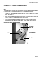
Diagram 4.39 - Multi Hip Cam
Multi Hip Cam
Cable to Cam
Mounting Bolt
Multi Hip Pulleys
Multi Hip
Upright Pulley
6.
Feed the cable between the two multi hip pulleys. See Diagram 4.39. Fasten the cable to
the multi hip cam with the jam nut and locknut. Ensure that the cable will pivot freely after
the jam and locknuts are tight.
Page 38
Consumer Strength Equipment
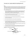
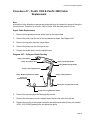
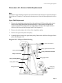
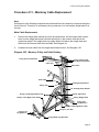
Procedure 4.5 - Newport Cable Replacement
Note:
All directions in the following procedures are referenced from the viewpoint of a person facing the
front of the unit. Therefore, on a Newport the chest press is in front and the weight stack is in the
right. Several versions of the Newport were manufactured. In order to determine the correct
version the existing cable will either be measured or the part number (e.g. XU-158-2) stamped on
the cable will be referenced.
Main Cable Replacement
1.
Remove the weight stack selector pin from the weight stack. Lift the weight stack selector
stem from the weight stack and insert the selector pin in the selector stem above the
uppermost weight. The weight stack top weight will be held above the weight stack and
tension will be removed from the main cable. See Diagram 4.1.
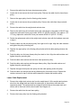
2.
Support the press arm and remove the bolt that fastens the cable to the weight stack
selector stem. Allow the press arm to rest against the main upright.
3.
Remove the lat pulldown bar and spring clip.
4.
Remove the pulley from the pulley bracket directly over the weight stack.
5.
Remove the upper pulley from the floating pulley bracket in front of the main upright.
6.
There are three pulleys in the rear portion of the lat pulldown top beam and two pulleys in
the press arm. Remove all five of the pulleys. See Diagram 4.40.
Note: The pulleys in the press arm does not have a hub and use special spacers.
Diagram 4.40 - Main Cable Pulleys and Routing
Retaining
Bolt
Pulley Over
Weight Stack
Lat Pulldown
Top Beam
Press Arm
Page 39
Consumer Strength Equipment
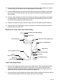
7.
Remove the pulley from the front end of the lat pulldown top beam. The pulley bolt also
retains the lat bar holder brackets. Remove the cable from the unit and measure the cable
length, also note the part number stamped on the cable. If the cable is 174-1/4” long,
replace it with Precor part number 40492-101 [HD-01-174-250]. If the cable is 163-5/8” long,
replace it with Precor part number 40446-101 [BC-163-625]. If the cable is 158-1/4” long,
replace it with Precor part number 42747-101. [158-250].
8.
Feed the weight stack end of the replacement cable into the front end of the lat pulldown top
beam and out the window in the lower middle portion of the lat pulldown top beam.
9.
Replace and tighten the pulley in the front of the lat pulldown top beam with the cable
passing under the retaining bolt and over the pulley.
10. Replace and tighten the foremost of the rear three pulleys in the lat pulldown top beam with
the cable passing over and around the pulley.
11. Replace and tighten the front press arm pulley, using a pulley without a hub and special
spacers, with the cable passing under and around the pulley.
12. Replace and tighten the middle of the rear three pulleys in the lat pulldown top beam with
the cable passing over and around the pulley from front to rear.
13. Replace and tighten the rear press arm pulley, using a pulley without a hub and special
spacers, with the cable passing under and around the pulley.
14. Replace and tighten the rearward of the rear three pulleys in the lat pulldown top beam with
the cable passing over and around the pulley from front to rear.
15. Replace and tighten the upper pulley in the front floating pulley bracket with the cable
passing between the pulleys.
16. Replace and tighten the pulley over the weight stack with the cable passing over and around
the pulley.
17. Fasten the cable to the weight stack selector stem with the bolt removed in step 2.
Pec Fly Cable Replacement
1.
Remove the weight stack selector pin from the weight stack. Lift the weight stack selector
stem from the weight stack and insert the selector pin in the selector stem above the
uppermost weight. The weight stack top weight will be held above the weight stack and
tension will be removed from the main cable. See Diagram 4.1.
2.
Remove the upper pulley from the rear floating pulley bracket. See Diagram 4.41
3.
Loosen, but do not remove the two pec fly pulleys on the rear of the main upright. See
Diagram 4.41.
Page 40
Consumer Strength Equipment
4.
Remove the cable from the left and right hand pec fly cams. Remove the cable from the unit
and measure the cable length, also note the part number stamped on the cable. If the cable
is 60-3/4” long, replace it with Precor part number 42759-101 [60-750]. If the cable is 113”
long, replace it with Precor part numbers 42951-101 & 42952-101 [113-000].
Diagram 4.41 - Pec Fly Pulleys and Cable Routing
Pec
Fly
Pulleys
Main
Upright,
Rear
Pec
Fly
Cam
5.
Fasten the replacement cable to the left hand pec fly cable.
6.
Feed the cable over and around the left hand pec fly pulley on the rear of the main upright.
Align the cable retainer and tighten the pulley.
7.
Replace and tighten the upper pulley in the rear floating pulley bracket with the cable
passing between the pulleys.
8.
Feed the cable over and around the right hand pec fly pulley on the rear of the main upright.
Align the cable retainer and tighten the pulley.
9.
Fasten the cable to the right hand pec fly cam. Remove the weight selector pin, lower the
weight stack top weight to the top of the weight stack.
Leg Extension Cable Replacement (without leg press option)
1.
Remove the weight stack selector pin from the weight stack. Lift the weight stack selector
stem from the weight stack and insert the selector pin in the selector stem above the
uppermost weight. The weight stack top weight will be held above the weight stack and
tension will be removed from the main cable. See Diagram 4.1.
Page 41
Consumer Strength Equipment
2.
Remove any attachments and spring clips from the low pull (leg extension) and ab crunch
ends of the cable.
3.
Remove the leg extension pulley. Loosen but do not remove the pulley under the leg
extension seat. See Diagram 4.42.
Diagram 4.42 - Leg Extension Pulleys and Cable Routing
Front
Upright
Front
Upright
(AB Crunch)
Front
Floating
Pulley
Rear
Upright
Rear
Upright
Rear
Floating
Pulley
Leg
Extension
Leg
Extension
Pulley
Pulley Under Seat
4.
Loosen but do not remove the two pulleys at the base of the rear upright (under the rear
floating pulley). See Diagram 4.42.
5.
Remove the lower pulley from the rear floating pulley bracket.
6.
Remove the lower pulley from the front floating pulley bracket.
7.
Remove the pulley mounted to the frame in front of the rear upright.
8.
Remove the pulley from the lower rear portion of the front upright.
9.
Remove the pulley from the window in the front upright (Ab crunch).
Page 42
Consumer Strength Equipment
10.
Remove the cable from the unit and measure the cable length, also note the part number
stamped on the cable. If the cable is 102” long, replace it with Precor part number
40493-101 [HB-04-102]. If the cable is 163-5/8” long, replace it with Precor part number
40446-101 [BC-163-625]. If the cable is 248-5/8” long, replace it with Precor part number
42748-101 [248-625].
11. Replace and tighten the pulley in the front upright window (ab crunch) with the replacement
cable passing over the pulley.
12. Replace and tighten the pulley at the lower rear portion of the front upright passing between
the upright and the pulley.
13. Replace and tighten the pulley on the frame in front of the rear upright with the cable
passing under and around the pulley.
14. Replace and tighten the lower pulley in the front floating pulley bracket with the cable
passing between the pulleys.
15. Feed the cable under and around the pulley at the right rear base of the rear upright. Align
the cable bracket and tighten the pulley mounting bolt.
16. Replace and tighten the lower pulley in the rear floating pulley bracket with the cable
passing between the pulleys.
17. Feed the cable under and around the pulley at the left rear base of the rear upright. Align the
cable bracket and tighten the pulley mounting bolt.
18. Feed the cable under the pulley under the leg extension seat. Align the cable bracket and
tighten the pulley mounting bolt.
19. Replace the leg extension pulley with the cable passing under the pulley.
Leg Extension Cable Replacement (with leg press option)
1.
Perform steps 1-6 of the previous procedure, leg extension cable replacement (without leg
press option).
2.
Loosen but do not remove the upper and lower leg press bracket pulleys and the leg press
support arm pulley. See Diagram 4.37.
3.
Remove the cable from the three pulleys in Diagram 4.37.
4.
Perform steps 7-14 of the previous procedure, leg extension cable replacement (without leg
press option).
5.
Feed the cable around the three pulleys as shown in Diagram 4.37. Align the cable brackets
and tighten the three pulley mounting bolts.
Page 43
Consumer Strength Equipment
6.
Feed the cable under and around the pulley at the right rear base of the rear upright. Align
the cable bracket and tighten the pulley mounting bolt.
7.
Replace and tighten the lower pulley in the rear floating pulley bracket with the cable
passing between the pulleys.
8.
Feed the cable under and around the pulley at the left rear base of the rear upright. Align the
cable bracket and tighten the pulley mounting bolt.
9.
Feed the cable under the pulley under the leg extension seat. Align the cable bracket and
tighten the pulley mounting bolt.
Page 44
Consumer Strength Equipment
Procedure 4.6 - Ventura & NSS 510 Cable Replacement
Note:
All directions in the following procedures are referenced from the viewpoint of a person facing the
front of the unit. Therefore, on a Ventura the chest press is in front and the weight stack is on the
right. The cable that emerges from the swivel pulley (left side of the frame, behind the weight
stack) may be used independently, connected to the pec fly floating pulley or the ab/torso cable.
Upper Cable Replacement
1.
Remove the weight stack selector pin from the weight stack. Lift the weight stack selector
stem from the weight stack and insert the selector pin in the selector stem above the
uppermost weight. The weight stack top weight will be held above the weight stack and
tension will be removed from the main cable. See Diagram 4.1.
2.
Remove the lat pulldown bar and spring clip from the cable end above the press arm.
Remove the cable from the weight stack selector stem.
3.
Loosen but do not remove the pulley directly above the weight stack.
4.
Remove the lower pulley from the floating pulley assembly. Remove the floating pulley
bracket from the upper cable.
5.
Remove both pulleys from the front frame upright (chest press upright).
6.
Remove both pulleys from the press arm. Remove the cable from the unit.
7.
Fasten the replacement cable (Precor part number 42738-101 [150-000] {94 & 95 Ventura},
42953-101 [151-500] {97 Ventura} or 42745-101 [105-500] {NSS 510}) to the weight stack
selector stem with the hardware removed in step 2.
8.
Feed the cable over and around the pulley directly above the weight stack. Align the cable
retainer and tighten the pulley mounting bolt.
9.
Feed the upper cable and lower cable through the floating pulley assembly, replace and
tighten the lower pulley in the floating pulley assembly. See Diagram 4.43 and 4.44.
Diagram 4.43 - Floating Pulley Assembly
Upper Cable
Floating Pulley Bracket
Lower Cable
Page 45
Consumer Strength Equipment
10. Feed the cable through the window in the chest press frame upright. Replace and tighten
the lower pulley in the window with the cable passing over the pulley.
11. Feed the cable between the press arm frame tubes. Replace the and tighten lower press
arm pulley with the cable passing under around pulley and back toward the chest press
frame upright.
12. Feed the cable through the window in the chest press frame upright. Replace and tighten
the upper pulley in the chest press frame upright with the cable passing under over and
around the pulley and back toward the press arm.
13. Replace and tighten the upper press arm pulley with the cable passing under the pulley.
14. Feed the cable over the top beam pulley (lat pulldown) and attach the spring clip and lat
pulldown bar to the cable end.
Diagram 4.44 - Upper and Lower Cable Routing
Top Beam (Lat Pulldown) Pulley
Upper Cable
Press Arm Pulleys
Chest Press Frame Upright Pulley
Pulley over Weight Stack
Weight Stack
Rear Leg Extension Pulley
Floating Pulley Assembly
Front Leg
Extension Pulley
Middle Leg
Extension Pulley
Lower Cable
Swivel Bracket Pulley
Lower Cable Replacement
1.
Remove the weight stack selector pin from the weight stack. Lift the weight stack selector
stem from the weight stack and insert the selector pin in the selector stem above the
uppermost weight. The weight stack top weight will be held above the weight stack and
tension will be removed from the lower cable. See Diagram 4.1.
2.
Remove the pec fly pulley bracket or ab/torso cable if either is attached to the lower cable at
the swivel pulley bracket. Remove the spring clip from the lower cable.
Page 46
Consumer Strength Equipment
3.
Remove the pulley from the swivel pulley bracket.
4.
Remove the lower pulley from the floating pulley bracket.
5.
Loosen but dot not remove the rear leg extension pulley.
6.
Remove the retainer bolt from under the middle leg extension pulley.
7.
Remove the front leg extension pulley. Remove the cable from the unit.
8.
Feed the replacement cable (Precor part number 42739-101 [132-500] {94 Ventura},
42733-101 [114-125] {95 Ventura} or 42746-101 [131-750], 42956-101 [131-813] {97
Ventura} or 42746-101 [43-125] (NSS 510}) and replace and tighten the front leg extension
pulley with the cable passing under the pulley. See Diagram 4.44.
9.
Feed the cable under the middle leg extension pulley and replace and tighten the retainer
bolt with the cable passing between the pulley and retainer bolt.
10. Feed the cable under the rear leg extension pulley, align the cable retainer and tighten the
pulley mounting bolt.
11. Replace the and tighten lower pulley in the floating pulley assembly with the cable passing
between the pulleys. See Diagram 4.43.
12. Replace and tighten the pulley in the swivel bracket with the cable passing under the pulley.
13. Attach the spring clip to the cable end at the swivel bracket. Attach the pec fly cable bracket
or ab/torso cable to the lower cable as required.
Pec Fly Cable Replacement
1.
Remove the weight stack selector pin from the weight stack. Lift the weight stack selector
stem from the weight stack and insert the selector pin in the selector stem above the
uppermost weight. The weight stack top weight will be held above the weight stack and
tension will be removed from the pec fly cable. See Diagram 4.1.
2.
Remove the pulley from the pec fly floating pulley bracket. See Diagram4.45.
3.
Remove both pec fly pulleys.
4.
Remove the cable ends to each pec fly arm. Remove the cable from the unit.
5.
Connect each end of the replacement cable (Precor part number 42734-101 [104-000] {94
Ventura}, 42740-101 [WW-105-3] {95 Ventura}, 42955-101 [106-250] (97 Ventura} or
42747-101 [158-250] {NSS 510}) to one of the pec fly arms.
6.
Replace and tighten both pec fly pulleys with the cable passing over and around the pulley.
See Diagram 4.45.
Page 47
Consumer Strength Equipment
Diagram 4.45 - Pec Fly Pulley and Cable Routing
Pec Fly Pulley
Pec Fly Cable
Pec Fly Arm
Swivel Pulley Bracket
7.
Replace and tighten the swivel pulley with the cable passing under the pulley.
Ab/Torso Cable Replacement
1.
If necessary, disconnect the ab/torso cable from the swivel pulley.
2.
Remove ab/torso pulley from the window in the rear frame upright. Remove the cable from
the unit.
3.
Feed the replacement cable (Precor part number 42755-101 [043-125] through the window
in the rear frame upright. Replace and tighten the ab/torso pulley with the cable passing
over the pulley.
4.
Reconnect the ab/torso cable to the swivel pulley as required.
Diagram 4.46 - Ab/Torso Pulley and Cable Routing
Ab/Torso Cable
Rear Frame Upright
Swivel pulley
Page 48
Consumer Strength Equipment
Procedure 4.7 - Pacific 1000 & Pacific 2000 Cable
Replacement
Note:
All directions in the following procedures are referenced from the viewpoint of a person facing the
front of the unit. Therefore, on a Pacific 1000 or Pacific 2000 the chest press is in front.
Upper Cable Replacement
1.
Remove the lat pulldown bar and spring clip from the upper cable.
2.
Remove the pulley from the end of the lat pulldown top beam. See Diagram 4.47.
3.
Remove the top pulley from the upright frame.
4.
Remove the pulley from the chest press arm.
5.
Remove the middle pulley from the upright frame.
Diagram 4.47 - Pulley and Cable Routing
Pulley, Lat Pulldown
Pulley, Chest Press Arm
Pulley, Top Upright Frame
Pulley, Middle Upright Frame
Pulley, Lower Upright Frame
Pulley, Middle Leg Extension Frame
Pulleys, Floating Bracket
Pulley, Leg
Extension Arm
Pulley, Rear Leg Extension Frame
Pulley, Front Leg Extension Frame
6.
Remove the top pulley from the floating pulley bracket.
7.
Remove the lower pulley from the upright frame. Remove the cable from the unit.
8.
Replace lower pulley in the upright frame with the replacement cable (Precor part number
42741-101[123-625]) passing over and behind the pulley.
Page 49
Consumer Strength Equipment
9.
Replace the top pulley in the floating pulley bracket with the cable passing between the
pulleys.
10. Replace the middle pulley in the frame upright with the cable passing over and in front of the
pulley.
11. Replace the chest press pulley with the cable passing under and around the pulley.
12. Replace the top pulley in the upright frame with the cable passing under and around the
pulley.
13. Replace the pulley in the lat pulldown top beam with the cable passing over the pulley.
14. Replace the spring clip and lat pulldown bar.
Lower Cable Replacement Pacific 1000 Only
1.
Remove the pulley from the leg extension arm.
2.
Remove the pulley from the front of the leg extension frame.
3.
Remove the pulley from the middle of the leg extension frame.
4.
Remove the lower pulley from the floating pulley bracket.
5.
Remove the pulley from the rear of the leg extension frame.
6.
Remove the bolt that fastens the cable to the rear of frame. Remove the cable from the unit.
7.
Replace the pulley in the leg extension arm with the replacement cable (Precor part number
42742-101 [104-375]) with the cable passing under the pulley.
8.
Replace the pulley in the front of the leg extension frame with the cable passing under the
pulley.
9.
Replace the pulley in the middle of the leg extension frame with the cable passing under the
pulley.
10. Replace the lower pulley in the floating pulley bracket with the cable passing between the
pulleys.
11. Replace the pulley in the rear of the leg extension frame with the cable passing under and
around the pulley.
12. Fasten the cable to the rear of the frame with the hardware removed in step 5.
Page 50
Consumer Strength Equipment
Lower Cable Replacement Pacific 2000 Only
1.
Remove the pulley from the leg extension arm.
2.
Remove the pulley from the front of the leg extension frame.
3.
Remove the pulley from the middle of the leg extension frame.
4.
Remove the lower pulley from the floating pulley bracket.
5.
Remove the pulley from the rear of the leg extension frame.
6.
Remove the pulley from the pre-stretch assembly. The pre-stretch assembly is attached to
the rear of the leg extension frame. See Diagram 4.48.
Diagram 4.48 - Pre-Stretch Pulley and Cable Routing
Pulleys, Floating Bracket
Pulley, Pre-Stretch
Pulley, Middle Leg
Extension Frame
Pulley, Rear Leg Extension Frame
7.
Remove the bolt that fastens the cable to the rear of frame. Remove the cable from the unit.
8.
Replace the pulley in the leg extension arm with the replacement cable (Precor part number
40626-101 [BM139-250]) with the cable passing under the pulley.
9.
Replace the pulley in the front of the leg extension frame with the cable passing under the
pulley.
10. Replace the pulley in the middle of the leg extension frame with the cable passing under the
pulley.
11. Replace the lower pulley in the floating pulley bracket with the cable passing between the
pulleys.
12. Replace the pulley in the rear of the leg extension frame with the cable passing under and
around the pulley.
Page 51
Consumer Strength Equipment
13. Replace the pulley in the pre-stretch assembly with cable passing over and around the
pulley.
14. Fasten the cable to the rear of the frame with the hardware removed in step 5.
Page 52
Consumer Strength Equipment
Procedure 4.8 - Encore Cable Replacement
Note:
All directions in the following procedures are referenced from the viewpoint of a person facing the
front of the unit. Therefore, on an Encore the chest press is in front and the weight stack is on the
right.
Upper Cable Replacement
1.
Remove the weight stack selector pin from the weight stack. Lift the weight stack selector
stem from the weight stack and insert the selector pin in the selector stem above the
uppermost weight. The weight stack top weight will be held above the weight stack and
tension will be removed from the upper cable. See Diagram 4.1.
2.
Remove the cable retainer bolt in front of the lat pulldown pulley.
3.
Remove the upper chest press arm pulley.
4.
Loosen but do not remove the upper frame pulley. Remove the cable from the upper frame
pulley. See Diagram 4.49.
Diagram 4.49 - Pulley and Cable Routing
Pulley, Lat Pulldown
Pulley, Upper Chest Press Arm
Pulley, Pre-Stretch
Pulley, Lower Chest Press Arm
Pulley, Lower Frame
Pulleys, Floating Bracket
Pulley, Upper Frame
Pulley, Front Frame
Pulley, Rear Frame
Pulley, Leg
Extension
Page 53
Consumer Strength Equipment
5.
Remove the cable from the lower chest press arm pulley.
6.
Loosen but do not remove the lower frame pulley. Remove the cable from the lower frame
pulley.
7.
Remove the upper pulley from the floating pulley bracket.
8.
Loosen but do not remove the pre-stretch pulley. Remove the cable from the pre-stretch
pulley.
9.
Remove the cable from the weight stack selector stem.
10. Remove the cable from the unit and measure the cable length. If the cable is 168-5/8” long,
replace the cable with Precor part number 40539-101 [HD-04-168-625]. If the cable is 1741/4” long, replace the cable with Precor part number 40492-101 [HD-01-174-250].
11. Fasten the replacement cable to the weight stack selector stem with the hardware removed
in step 9.
12. Feed the cable over the pre-stretch pulley from right to left to right. Align the cable retainers
and tighten the pulley mounting bolt.
13. Replace the upper pulley in the floating pulley bracket with the cable passing between the
pulleys.
14. Feed the cable over the lower frame pulley from back to front. Align the cable retainer and
tighten the pulley mounting bolt.
15. Feed the cable under and around the lower chest press arm pulley.
16. Feed the cable under and around the upper frame pulley. Align the cable retainer and
tighten the pulley mounting bolt.
17. Replace the upper chest press arm pulley with the cable passing under the pulley.
18. Feed the cable over and around the lat pulldown pulley from back to front. Replace the
retainer removed in step 2 with the cable between the retainer bolt and the pulley.
Lower Cable Replacement
1.
Remove the weight stack selector pin from the weight stack. Lift the weight stack selector
stem from the weight stack and insert the selector pin in the selector stem above the
uppermost weight. The weight stack top weight will be held above the weight stack and
tension will be removed from the lower cable. See Diagram 4.1.
2.
Remove the cable from the rear frame pulley.
3.
Remove the lower pulley from the floating pulley bracket.
Page 54
Consumer Strength Equipment
4.
Remove the front frame pulley.
5.
Loosen but do not remove the leg extension pulley.
6.
Remove the bolt the fastens the cable to the leg extension arm.
7.
Fasten the replacement cable (Precor part number 40588-101 [AB-137-250]) to the leg
extension arm with the hardware removed in step 5.
8.
Feed the cable under the leg extension pulley. Align the cable retainer and tighten the pulley
mounting bolt.
9.
Replace the front frame pulley with the cable passing under and around the pulley.
10. Replace the lower pulley in the floating pulley bracket with the cable between the pulleys.
11. Fed the cable under the rear frame pulley and insert the ball end of the cable into the cable
guard.
Page 55
Consumer Strength Equipment
Procedure 4.9 - Premier Cable Replacement
Note:
All directions in the following procedures are referenced from the viewpoint of a person facing the
front of the unit. Therefore, on an Premier the chest press is in front and the weight stack is on
the left.
Upper Cable Replacement
1.
Remove the weight stack selector pin from the weight stack. Lift the weight stack selector
stem from the weight stack and insert the selector pin in the selector stem above the
uppermost weight. The weight stack top weight will be held above the weight stack and
tension will be removed from the upper cable. See Diagram 4.1.
2.
Remove the lat pulldown bar and spring clip. Remove the retainer bolt from in front of the lat
pulldown pulley. See Diagram 4.50.
Diagram 4.50 - Pulley and Cable Routing
Pulley, Lat Pulldown
Pulley, Middle Top Beam
Pulley, Rear
Top Beam
Pulley, Upper Chest Press Arm
Pulley, Lower Chest Press Arm
Pulley, Middle Frame Upright
Pulley, Ab/Torso
Pulley, Pre-Stretch
Pulleys, Floating
Bracket
Pulley Upper
Frame Upright
Pulley Lower
Frame Upright
Pulley, Middle Frame
Pulley, Leg Extension
Pulley, Rear Frame
3.
Remove the upper chest press arm pulley.
4.
Remove the upper frame upright pulley. Remove the cable from the lower chest press arm
pulley.
Page 56
Consumer Strength Equipment
5.
Loosen but do not remove the middle frame upright pulley. Remove the cable from the
middle frame upright pulley.
6.
Loosen but do not remove the pre-stretch pulley. Remove the cable from the pre-stretch
pulley.
7.
Remove the rear top beam pulley.
8.
Remove the upper pulley from the floating pulley bracket.
9.
Remove the middle top beam pulley.
10. Remove the cable from the weight stack selector stem. Remove the cable from the unit and
measure the cable length.
11. If the cable is 293-7/8” long, replace it with Precor part number 40553-101 [HD-03-293-875].
If the cable is 299-1/2” long, replace it with Precor part number 40554-101 [HD-02-299-500].
12. Fasten the replacement cable to the weight stack selector stem with the hardware removed
in step 10.
13. Replace the middle top beam pulley with the cable over and around the pulley from left to
right.
14. Replace the upper pulley in the floating pulley bracket with the cable between the pulleys.
15. Replace the rear top beam pulley with the cable over and around the pulley from back to
front. Place the cable on the pre-stretch pulley so that the cable runs from back to front.
Align the cable retainer and tighten the pulley mounting bolt.
16. Feed the cable over the middle frame upright pulley from back to front. Align the cable
retainer and tighten the pulley mounting bolt.
17. Feed the cable under and around the lower chest press arm pulley.
18. Replace the upper frame upright pulley with the cable passing under and around the pulley.
Align the cable retainer and tighten the pulley mounting bolt.
19. Replace the upper chest press arm pulley with the cable passing under the pulley.
20. Feed the cable over the lat pulldown pulley from back to front. Replace the retainer bolt with
the cable between the bolt and the pulley.
Lower Cable Replacement
1.
Remove the weight stack selector pin from the weight stack. Lift the weight stack selector
stem from the weight stack and insert the selector pin in the selector stem above the
uppermost weight. The weight stack top weight will be held above the weight stack and
tension will be removed from the lower cable. See Diagram 4.1.
Page 57
Consumer Strength Equipment
2.
Remove the bolt that fastens the cable to the leg extension arm.
3.
Remove the middle frame pulley.
4.
Remove the lower pulley from the floating pulley bracket.
5.
Remove the rear frame pulley.
6.
Fasten the replacement cable (Precor part number 40556-101 [HB-03-156-750]) to the leg
extension arm with the hardware removed in step 2.
7.
Replace the middle frame pulley with the cable passing under and around the pulley.
8.
Replace the lower pulley in the floating pulley bracket with the cable passing between the
pulleys.
9.
Replace the rear frame pulley with the cable passing under the pulley from back to front.
Ab/Torso Cable Replacement
1.
If necessary, un-clip the ab/torso cable from the lower cable. Remove the spring clips and
ab/torso strap from the ab/torso cable.
2.
Remove the ab/torso pulley. Remove the cable from the unit.
3.
Replace the ab/torso pulley with the replacement cable (Precor part number 40577-101
[AA-48-000]) passing over the pulley. Align the cable retainer and tighten the pulley
mounting bolt.
4.
Replace the spring clips and ab/torso strap on the cable. If required clip the ab/torso cable to
the lower cable.
Page 58
Consumer Strength Equipment
Procedure 4.10 - System 4 Cable Replacement
Note:
All directions in the following procedures are referenced from the viewpoint of a person facing the
front of the unit. The System 4 is a four station, 4 weight stack unit. Each station will be
addressed individually. Therefore, on a System 4 the weight stack is in the rear of the station
being addressed.
Upper Lat/Preacher Curl Cable Replacement
1.
Remove the weight stack selector pin from the weight stack. Lift the weight stack selector
stem from the weight stack and insert the selector pin in the selector stem above the
uppermost weight. The weight stack top weight will be held above the weight stack and
tension will be removed from the upper cable. See Diagram 4.1.
2.
Remove the retainer bolt from in front of the lat pulldown pulley. See Diagram 5.51.
Diagram 5.51 - Lat/Preacher Curl Pulley and Cable Routing
Pulley, Lat Pulldown
Pulley, Weight Stack
Pulley, Top Frame
Pulleys, Floating Bracket
Pulley, Preacher Curl
Pulley,
l
Rear Frame
3.
Remove the upper pulley from the floating pulley bracket.
4.
Remove the weight stack pulley.
5.
Unfasten the cable from the weight stack selector stem. Remove the cable from the unit.
Page 59
Consumer Strength Equipment
6.
Fasten the replacement cable (Precor part number 40544-101 [HD-05-132]) to the weight
stack selector stem with the hardware removed in step 5.
7.
Replace the weight stack pulley with the cable passing over the cable right to left.
8.
Replace the upper pulley in the floating pulley bracket with the cable between the pulleys.
9.
Feed the cable over the top frame pulley from back to front.
10. Replace the retainer bolt with the cable passing between the retainer bolt and the pulley.
Lower Lat/Preacher Curl Cable Replacement
1.
Remove the weight stack selector pin from the weight stack. Lift the weight stack selector
stem from the weight stack and insert the selector pin in the selector stem above the
uppermost weight. The weight stack top weight will be held above the weight stack and
tension will be removed from the lower cable. See Diagram 4.1.
2.
Remove the preacher curl pulley. See Diagram 4.51.
3.
Remove the lower pulley from the floating pulley bracket.
4.
Remove the rear frame pulley. Remove the cable from the unit.
5.
Replace the rear frame pulley with the replacement cable (Precor part number 40607-101
[BB-115-875]) passing under and around the pulley from front to rear.
6.
Replace the lower pulley in the floating pulley bracket with the cable passing between the
pulleys.
7.
Replace the preacher curl pulley with the cable behind and under the pulley. Align the cable
retainer and tighten the pulley mounting bolt.
Squat Main Cable Replacement
1.
Remove the weight stack selector pin from the weight stack. Lift the weight stack selector
stem from the weight stack and insert the selector pin in the selector stem above the
uppermost weight. The weight stack top weight will be held above the weight stack and
tension will be removed from the squat cables. See Diagram 4.1.
2.
Un-clip the squat main cable from the squat press arm cable. See Diagram 4.52.
3.
Loosen but do not remove the lower squat pulley.
4.
Unfasten the cable from the weight stack selector stem. Remove the cable from the unit.
5.
Measure the length of the cable. If the cable is 146-3/4” long, replace it with Precor part
number 40598-101 [AC-146-750]. If the cable is 141-1/8”” long, replace it with Precor part
number 40596-101 [AC-141-125].
Page 60
Consumer Strength Equipment
Diagram 4.52 - Squat Pulleys and Cable Routing
Pulley, Upper Squat
Squat Main Cable
Pulley, Squat Press Arm
Squat Press Arm Cable
Pulley, Lower Squat
6.
Fasten the replacement cable to the weight stack selector stem.
7.
Feed the cable over and around the upper squat pulley from back to front.
8.
Feed the cable around the lower squat pulley from back to front. Align the cable retainer and
tighten the pulley mounting bolt.
9.
Clip the squat main cable to the squat press am cable.
Squat Press Arm Cable Replacement
1.
Remove the weight stack selector pin from the weight stack. Lift the weight stack selector
stem from the weight stack and insert the selector pin in the selector stem above the
uppermost weight. The weight stack top weight will be held above the weight stack and
tension will be removed from the squat cables. See Diagram 4.1.
2.
Un-clip the squat main cable from the squat press arm cable. See Diagram 4.52.
3.
Remove the squat press arm pulley.
4.
Remove the bolt that fastens the cable to the press arm stop. Remove the cable from the
unit.
5.
Fasten the replacement cable (Precor part number 40576-101 [AA-34-000]) to the press
arm stop with the hardware removed in step 4.
6.
Replace the press arm pulley with the cable passing over the pulley from back to front.
Page 61
Consumer Strength Equipment
7.
Clip the squat press arm cable to the squat main cable.
Chest Press Cable Replacement
1.
Remove the weight stack selector pin from the weight stack. Lift the weight stack selector
stem from the weight stack and insert the selector pin in the selector stem above the
uppermost weight. The weight stack top weight will be held above the weight stack and
tension will be removed from the chest press cable. See Diagram 4.1.
2.
Unfasten the cable from the weight stack. See Diagram 4.53.
Diagram 4.53 - Chest Press Pulley and Cable Routing
Pulley, Weight Stack
Pulley, Upper Press Arm
Pulley, Lower Press Arm
Pulley, Lower Frame
Pulley, Upper Frame
Pulley, Pre-Stretch
3.
Remove the pre-stretch pulley.
4.
Loosen but do not remove the lower frame pulley. Remove the cable from the pulley.
5.
Remove the lower press arm pulley.
6.
Loosen but do not remove the upper frame pulley. Remove the cable from the pulley.
7.
Unfasten the cable from the frame eye-bolt. Remove the cable from the unit.
8.
Fasten the replacement cable (Precor part number 40542-101 [HC-05-259]) to the frame
eye-bolt.
9.
Feed the cable over and around the upper press arm pulley.
Page 62
Consumer Strength Equipment
10. Feed the cable over and around the upper frame pulley. Align the cable retainers and
tighten the pulley mounting bolt.
11. Replace the lower press arm pulley with the cable passing over and around the pulley.
12. Feed the cable over and behind the lower frame pulley. Align the cable retainer and tighten
the pulley mounting bolt.
13. Replace the pre-stretch pulley with the cable passing under and around the pulley from front
to back.
14. Feed the cable over the weight stack pulley from front to back.
15. Fasten the cable to the weight stack selector stem.
Leg Extension Cable Replacement
1.
Remove the weight stack selector pin from the weight stack. Lift the weight stack selector
stem from the weight stack and insert the selector pin in the selector stem above the
uppermost weight. The weight stack top weight will be held above the weight stack and
tension will be removed from the leg extension cable. See Diagram 4.1.
2.
Remove the bolt that fastens the cable to the leg extension arm. See Diagram 4.54.
Diagram 4.54 - Leg Extension Pulley and Cable Routing
Pulleys, Upper Frame
Pulley, Leg Extension
Pulley, Lower Frame
Page 63
Consumer Strength Equipment
3.
Loosen but do not remove the leg extension pulley. Remove the cable from the leg
extension pulley.
4.
Loosen but do not remove the lower frame pulley. Remove the cable from the lower frame
pulley.
5.
Unfasten the cable from the weight stack selector stem. Remove the cable from the unit.
6.
Fasten the replacement cable (Precor part number 40543-101 HC-06-193-625]) to the
weight stack selector stem.
7.
Feed the cable over the two upper frame pulleys from back to front.
8.
Feed the cable around the lower frame pulley from back to front. Align the cable retainer and
tighten the pulley mounting bolt.
9.
Feed the cable under the leg extension pulley. Align the cable retainer and tighten the pulley
mounting bolt.
10. Fasten the cable to the leg extension arm with the hardware removed in step 2.
Page 64
Consumer Strength Equipment
Procedure 4.11 - Monterey Cable Replacement
Note:
All directions in the following procedures are referenced from the viewpoint of a person facing the
front of the unit. Therefore, on a Monterey the leg extension is in front and the weight stack is in
the rear.
Main Cable Replacement
1.
Remove the weight stack selector pin from the weight stack. Lift the weight stack selector
stem from the weight stack and insert the selector pin in the selector stem above the
uppermost weight. The weight stack top weight will be held above the weight stack and
tension will be removed from the main cable. See Diagram 4.1.
2.
Unfasten the main cable from the weight stack selector stem. See Diagram 4.55.
Diagram 4.55 - Monterey Pulley and Cable Routing
Pulley, Front Lat Pulldown
Pulleys, Upper Frame
Pulley, Rear Lat Pulldown
Cable Tree
Main Cable
Row Cable
Floating Pulley Bracket
Pulley, Row
90° Floating Pulley Bracket
Pulleys, Left & Right Upper Frame
Pulleys, Upper Arm
Pulleys, Left & Right Lower Frame
Pulley, Weight Stack
Pulley, Rear
Leg Extension
Pulleys, Left & Right Rear Frame
Pulleys, Lower Arm
Pulley, Front
Leg Extension
Pulley, Middle Leg Extension
Page 65
Consumer Strength Equipment
3.
Loosen but do not remove the two upper frame pulleys.
4.
Remove the bolt that fastens the cable to the center of the cable tree. Remove the cable
from the unit.
5.
Fasten the replacement cable (Precor part number 40486-101 [CM-64-125]) to the weight
stack selector stem.
6.
Feed the cable over the two upper frame pulleys from right to left. Align the cable retainers
and tighten the pulley mounting bolts.
7.
Feed the cable into the center of the cable tree and fasten the cable with the hardware
removed in step 4. Remove the weight stack selector pin (step 1) and adjust the nut that
fastens the main cable to cable tree until the weight stack top weight sits squarely on the
weight stack and all excess slack is removed from the cable.
Bench/Fly Cable Replacement
1.
Remove the weight stack selector pin from the weight stack. Lift the weight stack selector
stem from the weight stack and insert the selector pin in the selector stem above the
uppermost weight. The weight stack top weight will be held above the weight stack and
tension will be removed from the bench fly cable. See Diagram 4.1.
2.
Rotate and lock the bench fly mechanism so that it is perpendicular to the floor.
3.
Unfasten the cable from the left hand bench fly arm.
4.
Remove the cable from the upper and lower right arm pulleys. See Diagram 4.55. Remove
the cable from the upper and lower right frame pulleys.
5.
Remove the right rear frame pulley.
6.
Remove the lower pulley from the 90° floating pulley bracket.
7.
Remove the left rear frame pulley.
8.
Remove the cable from the upper and lower left frame pulleys. Remove the cable from the
upper and lower left arm pulleys.
9.
Unfasten the cable from the right hand bench fly arm.
10. Fasten the replacement cable (Precor part number 40487-101 [II-269-500]) to the right hand
bench fly arm with the hardware removed in step 9.
11. Feed the cable the over the upper left hand arm pulley from right to left. Feed the cable
under and around the lower left hand arm pulley.
12. Feed the cable over and around the upper left frame pulley. Feed the cable over around and
under the lower left frame pulley.
Page 66
Consumer Strength Equipment
13. Replace the left rear frame pulley with the cable passing under and around the pulley.
14. Replace the lower pulley in the 90° floating pulley bracket with the cable passing between
the pulleys.
15. Replace the right rear frame pulley with the cable passing under the pulley.
16. Feed the cable under and around the lower right frame pulley. Feed the cable over and
around the upper right frame pulley.
17. Feed the cable under and around the lower right hand arm pulley. Feed the cable over the
upper right hand arm pulley.
18. Fasten the cable to the left hand bench fly arm with the hardware removed in step 3.
Lat Pulldown cable Replacement
1.
Remove the weight stack selector pin from the weight stack. Lift the weight stack selector
stem from the weight stack and insert the selector pin in the selector stem above the
uppermost weight. The weight stack top weight will be held above the weight stack and
tension will be removed from the lat pulldown cable. See Diagram 4.1.
2.
Remove the lat pulldown bar and spring clip from the lat pulldown cable. See Diagram 4.55.
3.
Remove the front lat pulldown pulley.
4.
Remove the rear lat pulldown pulley.
5.
Remove the upper pulley from the floating pulley bracket.
6.
Remove the cable from the cable tree.
7.
Fasten the replacement cable (Precor part number 40488-101 [BK-140-250]) to the cable
tree with the hardware removed in step 5.
8.
Replace the upper pulley in the floating bracket with the cable passing between the pulleys.
9.
Replace the rear lat pulldown pulley with the cable passing over the pulley from back to
front.
10. Replace the front lat pulldown pulley with the cable between the pulley and the retainer bolt.
11. Replace the spring clip and lat pulldown bar.
Page 67
Consumer Strength Equipment
Leg Extension Cable Replacement
1.
Remove the weight stack selector pin from the weight stack. Lift the weight stack selector
stem from the weight stack and insert the selector pin in the selector stem above the
uppermost weight. The weight stack top weight will be held above the weight stack and
tension will be removed from the lat pulldown cable. See Diagram 4.1.
2.
Remove the retainer bolt from under the front leg extension pulley. See Diagram 4.55.
3.
Remove the rear leg extension pulley.
4.
Remove the lower pulley from the floating pulley bracket.
5.
Remove the weight stack pulley.
6.
Unfasten the cable from the left side of the frame.
7.
Fasten the replacement cable (Precor part number 40480-101 [BI-188-875]) to the left side
of the frame with the hardware removed in step 5.
8.
Replace the weight stack pulley with the cable passing under and around the pulley.
9.
Replace the lower pulley in the floating pulley bracket with the cable passing between the
pulleys.
10. Replace the rear leg extension pulley with the cable passing under the pulley from back to
front.
11. Feed the cable under the middle leg extension pulley.
12. Replace the retainer bolt (step 2) with the cable passing between the retainer bolt and the
front leg extension pulley.
Row Cable Replacement
1.
Remove the weight stack selector pin from the weight stack. Lift the weight stack selector
stem from the weight stack and insert the selector pin in the selector stem above the
uppermost weight. The weight stack top weight will be held above the weight stack and
tension will be removed from the row cable. See Diagram 4.1.
2.
Remove the row handle from the cable. Remove the row pulley.
3.
Remove the upper pulley from the 90° floating pulley bracket.
4.
Unfasten the cable from the cable tree.
5.
Fasten the replacement cable (Precor part number 40489-101 [BB-77-250]) to the cable
tree with the hardware removed in step 3.
Page 68
Consumer Strength Equipment
6.
Replace the upper pulley in the 90° floating pulley bracket with the cable passing between
the pulleys.
7.
Replace the row pulley with the cable passing over the pulley. Replace the row handle.
Page 69
Consumer Strength Equipment
Procedure 4.12 - Profile 7.5 Cable Replacement
Note:
All directions in the following procedures are referenced from the viewpoint of a person facing the
front of the unit. Therefore, on a Profile 7.5 the leg extension is in front and the weight stack is in
the rear.
Main Cable Replacement
1.
Remove the weight stack selector pin from the weight stack. Lift the weight stack selector
stem from the weight stack and insert the selector pin in the selector stem above the
uppermost weight. The weight stack top weight will be held above the weight stack and
tension will be removed from the main cable. See Diagram 4.1.
2.
Un-clip the main cable from the weight stack selector stem and remove the spring clip.
3.
Remove the lower main cable pulley (in swivel pulley housing).
4.
Un-clip the other end of the main cable from the press arm, lat pulldown cable or leg
extension cable as required. Remove the spring clip.
5.
Remove the cable from the unit. Measure the cable length. If the cable is 128-1/4” inches
long, the replacement cable is Precor part number 40547-101 [DC-01-128-250]. If the cable
is 120-1/8” inches long, the replacement cable is Precor part number 40545-101
[DC-05-120-125].
6.
Clip the replacement cable the weight stack selector stem with the spring clip removed in
step 2.
7.
Feed the cable over the upper main cable pulley from front to rear.
8.
Replace the lower main cable pulley with the cable passing behind and around the pulley.
9.
Clip the main cable to the press arm, lat pulldown cable or leg extension cable as required
With the spring clip removed in step 4.
Leg Extension Cable Replacement
1.
Remove the weight stack selector pin from the weight stack. Lift the weight stack selector
stem from the weight stack and insert the selector pin in the selector stem above the
uppermost weight. The weight stack top weight will be held above the weight stack and
tension will be removed from the leg extension cable. See Diagram 4.1.
2.
If necessary, un-clip the leg extension cable from the main cable.
3.
Remove the bolt that fastens the cable to the leg extension arm. Remove the cable from the
unit.
Page 70
Consumer Strength Equipment
4.
Fasten the replacement cable to the leg extension arm with the hardware removed in step 3.
5.
Feed the cable under the leg extension pulley.
6.
Clip the cable to the main cable.
Lat Pulldown Cable Replacement
1.
Remove the weight stack selector pin from the weight stack. Lift the weight stack selector
stem from the weight stack and insert the selector pin in the selector stem above the
uppermost weight. The weight stack top weight will be held above the weight stack and
tension will be removed from the lat pulldown cable. See Diagram 4.1.
2.
If necessary, un-clip the lat pulldown cable from the main cable.
3.
Remove the front lat pulldown pulley (mounted on the top beam). Remove the cable from
the unit.
4.
Clip the replacement cable (Precor part number 40546-101 [DC-02-80-750] to the main
cable.
5.
Feed the cable behind and over the rear lat pulldown pulley.
6.
Replace the front lat pulldown pulley with the cable passing over and in front of the pulley.
Page 71
Consumer Strength Equipment
Procedure 4.13 - PacFit XV Cable Replacement
Note:
All directions in the following procedures are referenced from the viewpoint of a person facing the
front of the unit. Therefore, on a PacFit XV the leg extension is in front and the weight stack is in
the rear.
Main Cable Replacement
1.
Remove the weight stack selector pin from the weight stack. Lift the weight stack selector
stem from the weight stack and insert the selector pin in the selector stem above the
uppermost weight. The weight stack top weight will be held above the weight stack and
tension will be removed from the main cable. See Diagram 4.1.
2.
Remove the main cable from the weight stack selector stem.
3.
Remove the lower main cable pulley (mounted in a pulley swivel bracket).
4.
If necessary, un-clip the main cable from the leg extension, lat pulldown or chest press
cable. Remove the spring clip. Remove the cable from the unit and measure the cable. If the
cable is 146-3/4” long, replace it with Precor part number 40598-101 [AC-146-750]. If the
cable is 141-1/8” long, replace it with Precor part number 40532-101 [HC-02-141-125].
5.
Fasten the replacement main cable to weight stack selector stem with the hardware
removed in step 2.
6.
Feed the cable behind, over and around the upper main cable pulley.
7.
Replace the lower main cable pulley with the cable passing behind and under the pulley.
8.
Replace the spring clip removed in step 4 and clip the main cable to the leg extension, lat
pulldown or chest press cable as required.
Leg Extension Cable Replacement
1.
Remove the weight stack selector pin from the weight stack. Lift the weight stack selector
stem from the weight stack and insert the selector pin in the selector stem above the
uppermost weight. The weight stack top weight will be held above the weight stack and
tension will be removed from the leg extension cable. See Diagram 4.1.
2.
If necessary, un-clip the leg extension cable from the main cable.
3.
Remove the bolt that fastens the cable to the leg extension arm. Remove the cable from the
unit
4.
Fasten the replacement cable (Precor part number 40575-101 [AA-25-625]) to the leg
extension arm with the hardware removed in step 3.
Page 72
Consumer Strength Equipment
5.
Clip the leg extension cable to the main cable.
Lat Pulldown Cable Replacement
1.
Remove the weight stack selector pin from the weight stack. Lift the weight stack selector
stem from the weight stack and insert the selector pin in the selector stem above the
uppermost weight. The weight stack top weight will be held above the weight stack and
tension will be removed from the lat pulldown cable. See Diagram 4.1.
2.
If necessary, un-clip the lat pulldown cable from the main cable.
3.
Loosen but do not remove the front and rear lat pulldown pulleys (mounted on top beam).
Remove the cable from the unit.
4.
Clip the replacement cable (Precor part number 40531-101 [DC-09-97-750]) to the main
cable.
5.
Feed the cable behind and over the rear lat pulldown pulley. Align the cable retainer and
tighten the pulley mounting bolt.
6.
Feed the cable over and around the front lat pulldown pulley. Align the cable retainer and
tighten the pulley mounting bolt.
Chest Press Cable Replacement
1.
Remove the weight stack selector pin from the weight stack. Lift the weight stack selector
stem from the weight stack and insert the selector pin in the selector stem above the
uppermost weight. The weight stack top weight will be held above the weight stack and
tension will be removed from the Chest press cable. See Diagram 4.1.
2.
If necessary, un-clip the chest press cable from the main cable.
3.
Remove the bolt that fastens the cable to the frame upright.
4.
Remove the pulley mounted on the chest press arm. Remove the cable from the unit.
5.
Fasten the replacement cable (Precor part number 40530-101 [DC-08-69-500]) to the frame
upright with the hardware removed in step 3.
6.
Replace the pulley on the chest press arm with the cable passing around the pulley from
right to left with the hardware removed in step 4.
7.
Feed the cable over and behind the pulley mounted on the frame upright.
8.
Clip the chest press cable to the main cable.
Page 73
Consumer Strength Equipment
Procedure 4.14 - Solana (white and gray) Cable Replacement
Note:
All directions in the following procedures are referenced from the viewpoint of a person facing the
front of the unit. Therefore, on a Solana the leg extension is in front and the weight stack is in the
rear.
Main Cable Replacement
1.
Remove the weight stack selector pin from the weight stack. Lift the weight stack selector
stem from the weight stack and insert the selector pin in the selector stem above the
uppermost weight. The weight stack top weight will be held above the weight stack and
tension will be removed from the main cable. See Diagram 4.1.
2.
Remove the main cable from the weight stack selector stem. See Diagram 4.55.
Diagram 4.56 - Solana Main Cable
Upper Main
Frame Pulley
Rear Top
Beam Pulley
Front Top
Beam Pulley
Upper Left
Pulley
Upper Right
Pulley
Main Cable
Upper Press
Arm Pulley
Lower Press
Arm Pulley
Lower Main
Frame Pulley
Upper Floating Pulley
Page 74
Consumer Strength Equipment
3.
Remove the upper right and upper left pulleys.
4.
Remove the upper pulley from the floating pulley assembly.
5.
Remove the lower main frame pulley.
6.
Feed the weight stack end of the cable under the lower press arm pulley so that the cable is
hanging out of the front of the press arm. It is not necessary to remove the lower press arm
pulley. Feed the cable back over the lower press arm pulley. The cable should now be
hanging from the upper main frame pulley.
7.
Feed the weight stack end of the cable under the upper press arm pulley so that the cable is
hanging out of the front of the press arm. It is not necessary to remove the upper press arm
pulley. Feed the cable back over the upper press arm pulley. The cable should now be
hanging from the rear top beam pulley.
8.
Remove the rear and front top beam pulleys. Remove the cable from the unit.
9.
Feed the ball end of the replacement main cable (Precor part number 437496-101) up
through the opening in the top beam for the rear top beam pulley, over the top beam and
down through the opening for the front top beam pulley. Replace the front and rear top
beam pulleys.
10. Feed the weight stack end of the cable over, around and under the upper press arm pulley.
11. Replace the upper main frame pulley with the cable wrapped over, around and under the
pulley.
12. Feed the weight stack end of the cable over, around and under the lower press arm pulley.
13. Feed the weight stack end of the cable through the opening for the lower main frame pulley.
The cable should be hanging out of the rear of the main frame upright. Replace the lower
main frame pulley with the cable over the pulley.
14. Place the cable in the floating pulley assembly and replace the upper floating pulley with the
cable under the pulley. Ensure that the cable is passing from front to rear and that the lower
cable is not twisted.
15. Replace the upper left pulley with the cable passing over the pulley from left to right.
16. Replace the upper right pulley with the cable passing over the pulley from left to right.
17. Connect the cable to the weight stack selector stem and remove the weight stack selector
pin.
18. If necessary adjust the cable per Procedure 5.8.
Page 75
Consumer Strength Equipment
Lower Cable Replacement
1.
Remove the weight stack selector pin from the weight stack. Lift the weight stack selector
stem from the weight stack and insert the selector pin in the selector stem above the
uppermost weight. The weight stack top weight will be held above the weight stack and
tension will be removed from the main cable. See Diagram 4.1.
2.
Remove the lower cable from the leg ext. arm. See Diagram 4.57.
Diagram 4.57 - Leg Extension Arm
Leg Ext.
Arm
3.
Front Leg
Ext. Pulley
Remove the rear leg extensions pulley. See Diagram 4.58.
Diagram 4.58 - Lower Cable Pulleys
Cable
Retainer
Height
Adj. Pulley
Rear Frame
Pulley
Rear Leg
Ext. Pulley
Page 76
Consumer Strength Equipment
4.
Loosen but do not remove the height adjustment pulley and the rear frame pulley. Remove
the cable from the height adjustment and rear frame pulleys.
5.
Remove the lower pulley from the floating pulley assembly.
Diagram 4.59 - Lower Pulleys
Lower Left
Pulley
Lower Right
Pulley
Ball End
6.
Remove the lower left and lower right pulleys. Remove the cable from the unit.
7.
Lay the replacement cable (Precor part number 43903-101) between the lower pulley
flanges with the ball end to the right as shown in Diagram 4.59.
8.
Replace the lower right and lower pulleys with the cable under the pulleys.
9.
Feed the cable over the height adjustment pulley from front to rear. Reposition the cable
retainer and securely tighten the height adjustment pulley mounting bolt.
10. Feed the cable under the rear frame pulley from front to rear. Feed the cable over the height
adjustment pulley from front to rear. Reposition the cable retainer and securely tighten the
height adjustment pulley mounting bolt.
11. Place the cable in the floating pulley assembly and replace the lower floating pulley with the
cable over the pulley from rear to front.
Page 77
Consumer Strength Equipment
12. Feed the cable through the opening in the bottom of the main frame upright from rear to
front. Replace the rear leg extension pulley. Reposition the cable retainer and securely
tighten the rear leg extension pulley mounting bolt.
13. Feed the cable under the front leg extension pulley and fasten the cable to the leg extension
arm.
14. If necessary adjust the cable per Procedure 5.8
Press Arm Height Adjustment Cable Replacement
1.
If necessary set the press height adjustment at it’s lowest position. The height adjustment
arm should be resting on it’s support.
2.
Loosen the jam nut on the height adjustment cable and un-thread the height adjustment
cable from the height extender bracket. See Diagram 4.60.
Diagram 4.60 - Height Extender Bracket
Adjustment Cable
Jam Nut
Height Extender
Bracket
3.
Remove the adjustment cable from the height extender bracket.
4.
Remove the screw that fastens the adjustment cable to the hand release on the press arm.
See Diagram 4.61.
Page 78
Consumer Strength Equipment
Diagram 4.61 - Hand Release
Cable
Retaining
Screw
Adjustment
Cable
Retaining
Clip
Press
Arm
5.
Remove the retaining clip from the adjustment cable. Remove the cable from the press arm.
6.
Feed hand release end of the replacement cable (Precor part number 43747-101) into the
rear of the press arm until the end of the cable is visible in the access hole in the bottom of
the press arm. The access hole is directly opposite of cable hand release. Grasp the end of
the cable and feed it into it’s mounting hole as shown in Diagram 4.61. Fasten the
adjustment cable with the retaining clip removed in step 5.
7.
Fasten the adjustment cable to the hand release with the hardware removed in step 4.
8.
Securely thread the other end of the adjustment cable into the height extender bracket.
9.
Slide the cable into it’s support bracket and tighten the jam nut.
10. Ensure that the height adjustment hand release functions normally and that the height
adjuster moves freely throughout it’s entire range.
Page 79
Consumer Strength Equipment
Procedure 4.15 - S3.55 Cable Replacement
Note: All directions in the following procedures are referenced from the viewpoint of a person
facing the front of the unit. Therefore, on a Solana the leg extension is in front and the weight
stack is in the rear.
Lower Seat Adjustment Cable Replacement
1.
Move the seat adjustment lever toward the seat frame and remove the cable end from the
seat adjustment lever. See Diagram 4.62.
Diagram 4.62 - Seat Adjustment Lever
Seat
Adjustment
Cable
2.
Seat
Adjustment
Lever
Loosen the nuts that fasten the seat adjustment cable to the right hand side of the seat
carriage frame and remove the seat adjustment cable. See Diagram 4.63.
Diagram 4.63 - Seat Carriage Frame
Seat
Carriage
Frame
Seat
Adjustment
Cable
Page 80
Consumer Strength Equipment
3.
Remove the retaining screw from the cable mounting bracket. See Diagram 4.64. Cut the
cable tie fastening the seat adjustment cable to the lower frame cross member.
Diagram 4.64 - Adjustment Cable Mounting Bracket
Press Arm
Adjustment Cable
Cable
Mounting
Bracket
Retaining
Screw
Seat
Adjustment
Cable
4.
Remove and discard the seat adjustment cable.
5.
Fasten the replacement seat adjustment cable (part number 46414-101) and the press arm
cable to the cable mounting bracket as shown in Diagram 4.64 with the retaining screw
removed in step 3.
6.
Route the other end of the cable under the frame cross member and through both cable
clamps under the seat frame. Fasten the seat adjustment cable to the lower frame cross
member with a cable tie.
7.
Slide the seat adjustment cable into the slot in the right hand side of the seat carriage frame
as shown in Diagram 4.63. Tighten the nuts to secure the seat adjustment cable to the seat
carriage frame.
8.
Move the seat adjustment lever toward the seat frame and slide the cable into the slot in the
seat adjustment lever.
Press Arm Adjustment Cable Replacement
1.
Remove the screw that fastens the press arm adjustment cable to the cable mounting
Page 81
Consumer Strength Equipment
bracket. See Diagram 4.64.
2.
Remove the screw that fasten the other cable end to the press arm release lever. See
Diagram 4.65.
Diagram 4.65 - Press Arm Release Lever
Retaining
Clip
Release
Lever
Mounting
Screws
Release
Lever
Cable End
Retaining
Screw
3.
Remove the retaining from the press arm adjustment cable shown in Diagram 4.65.
4.
Remove the release lever mounting screws and remove the release lever from the press
arm. Remove the press arm adjustment cable from the release lever.
5.
Remove the press arm adjustment cable from the press arm and discard.
6.
Feed the replacement press arm adjustment cable (part number 46254-101) into the press
arm. Feed the press adjustment cable into the release lever and fasten it with the retaining
clip removed in step 3.
7.
Mount the release lever to the press arm with the screws removed in step 4. Fasten the
cable end to the release lever with the nut and screw removed in step 2.
8.
Fasten the other end of the press arm adjustment cable and the seat adjustment cable to
the cable mounting bracket with the retaining screw removed in step 1. See Diagram 4.64.
Inward Motion Adjustment Cable Replacement
1.
Unthread the inward motion cable and release mechanism from the rear of the press arm
assembly. See Diagrams 4.66 and 4.67.
2.
Unthread the cable end from the release mechanism using two end wrenches. Use one
wrench to hold the release mechanism on the flat surfaces and the other to unscrew the
Page 82
Consumer Strength Equipment
cable end. Slide the cable out of the slot at the top of the release mechanism. See Diagram
4.67.
Diagram 4.66 - Rear of Press Arm Assembly
Inward
Motion
Cable
Diagram 4.67 - Release Mechanism
Cable End
Slot
Flat
Cable
3.
Using a thin bladed screwdriver, pry the inward motion adjustment release button out of the
end of the press arm handle. See Diagram 4.68. Pull the inward motion adjustment Cable
out of the press arm handle.
Diagram 4.68 - Press Arm Handle
Release
Button
Press Arm
Handle
Page 83
Consumer Strength Equipment
4.
Remove the replacement inward motion adjustment cable (part number 46298-101) from its
release mechanism as described in step 2. Feed the replacement cable into the press arm
handle and out of the rear of the press arm. Press the release button firmly into the press
arm handle. Reinstall the release mechanism onto the inward motion adjustment cable.
5.
Thread the release mechanism into the rear of the press arm assembly. See Diagram 4.67.
Leg Press Cable Replacement
1.
The leg press is an option on the S3.55 and may not always be equipped.
1.
Raise the top weight up off of the weight stack and pin it in place as shown in Diagram 4.69.
This step removes tension from the cable being replaced and makes cable replacement
easier.
Diagram 4.69 - Top Weight Assembly
Top Weight
Assembly
Weight Pin
2.
Remove the nut and bolt that retains the pulley at the lower front portion of the leg press
frame. Remove the pulley. See Diagram 4.70.
Diagram 4.70 - Lower Leg Press Pulley
Pulley
Mounting
Hardware
Page 84
Consumer Strength Equipment
3.
This step refers to the group of five pulleys in the lower middle portion of the leg press
assembly. Refer to Diagram 4.71. Loosen but do not remove the mounting bolts on both
front pulleys and the rear pulley. Remove both middle pulleys. Remove the leg press cable
from the three remaining pulleys.
Diagram 4.71 - Leg Press Frame Assembly
Rear
Pulley
Front
Pulley
Cable
Retainer
4.
Middle
Pulley
Remove the pulley at the bottom right side of the weight stack. See Diagram 4.72.
Diagram 4.72 - Lower Weight Stack
Pulley
5.
Remove the leg press cable from the main cable at the upper right portion of the weight
stack frame. See Diagram 4.73. Remove and discard the leg press cable.
Page 85
Consumer Strength Equipment
Diagram 4.73 - Upper Weight Stack Frame Assembly
Main Cable
Leg Press Cable
or
Low Row Cable
6.
Fasten the replacement leg press cable (part number 46009-101) to the main cable with the
hardware removed in step 5. Feed the cable through the access hole at the bottom right
side of the weight stack and pull all of the cable out of the access hole.
7.
Replace and tighten the pulley at the lower right of the weight stack with the cable routed
under the pulley as shown in Diagram 4.72
8.
This step refers to the group of five pulleys in the lower middle portion of the leg press
assembly. Refer to Diagram 4.71. Route the leg press cable under and around the left front
pulley. Rotate the cable retainer into the correct position and tighten the pulley mounting
bolt. Replace the left middle pulley with the leg press cable routed over the pulley. Route the
leg press cable under and around the rear pulley. Rotate the cable retainer into the correct
position and tighten the pulley mounting bolt. Replace the right middle pulley with the leg
press cable routed over the pulley. Route the leg press cable under and around the rear
pulley. Route the leg press cable under the right front pulley. Rotate the cable retainer into
the correct position and tighten the pulley mounting bolt.
9.
Replace the pulley at lower front of the leg press assembly with the cable routed under the
pulley. See Diagram 4.70. Remove the pin from the weight stack and lower the top weight
onto the weight stack.
Page 86
Consumer Strength Equipment
Low Row Cable Replacement
1.
The low row Cable is only furnished when the S3.55 is not equipped with the leg press
option.
2.
Remove the pulley at the bottom right side of the weight stack. See Diagram 4.72.
3.
Remove the low row cable from the main cable at the upper right portion of the weight stack
frame. See Diagram 4.73. Remove and discard the leg press cable.
4.
Fasten the replacement low row cable (part number 46002-101)to the main cable with the
hardware removed in step 3. Feed the cable through the access hole at the bottom right
side of the weight stack and pull the cable out of the access hole.
5.
Replace and tighten the pulley at the lower right of the weight stack with the cable routed
under the pulley.
Main Cable Replacement
1.
Raise the top weight up off of the weight stack and pin it in place as shown in Diagram 4.69.
This step removes tension from the cable being replaced and makes cable replacement
easier.
2.
Using cable ties, fasten pulley bracket 2 and pulley bracket 4 to the frame brackets above
them. Refer to Diagrams 4.75 and 4.76.
3.
Remove the main cable from where it is fastened to the left side of the frame. See Diagram
4.74. Remove both nuts from the cable end.
Diagram 4.74 - Main Cable Mounting
Main Cable
Page 87
Consumer Strength Equipment
4.
With the nuts removed from the cable end, it will fit through the pulley brackets. Pull the
main cable end back through the pulley brackets numbered 1, 2 and 3 in Diagram 4.75.
Diagram 4.75 - Main Cable Pulley Brackets
Pulley
Bracket 3
Pulley
Bracket 1
Cable Tie
Pulley
Bracket 4
Pulley
Bracket 2
5.
Pull the main cable end back through pulley brackets 4,and 5 in Diagram 4.76. Remove the
main cable from pulley 6.
Diagram 4.76 - Main Cable Pulley Brackets
Pulley
Bracket 5
Pulley
Bracket 3
Cable Tie
Pulley
Bracket 4
Pulley 6
6.
Remove the screws that retain the cover at the top of the weight stack. Insert a piece of card
board or a cloth between the cover and the front pulley in Diagram 4.XX to protect the cover
when it is removed. Remove the cover. Loosen but do not remove the mounting bolts
retaining the four pulleys shown in Diagram 4.77. Remove the main cable from all four
pulleys.
Page 88
Consumer Strength Equipment
Diagram 4.77 - Top of Weight Stack Frame
7.
Remove the pulley at the top of the weight stack. See Diagram 7.78.
Diagram 4.78 - Top Weight Pulley
Pulley
8.
Remove the main cable from the leg press cable (when the leg press option is equipped) or
the low row cable (when the leg press option is not equipped). See Diagram 4.73. Remove
and discard the cable.
9.
Remove both nuts from the replacement main cable (part number 4606-101). Fasten the
replacement main cable to the leg press cable (when the leg press option is equipped) or
the low row cable (when the leg press option is not equipped) with the hardware remove in
step 8. See Diagram 4.73.
10. Route the main cable over the two right hand pulleys at the top of the weight stack frame as
shown in Diagram 4.77. Locate the cable retainers in the correct position and tighten the
mounting bolts on both pulleys.
Page 89
Consumer Strength Equipment
11. Replace the top weight pulley with the main cable routed under and around the pulley as
shown in Diagram 4.78. Tighten the pulley mounting bolts.
12. Route the main cable up and over the two remaining pulleys at the top of the weight stack
frame as shown in Diagram 4.77. Locate the cable retainers in the correct position and
tighten the mounting bolts on both pulleys.
13. Route the main cable under pulley 6, through pulley bracket 5 above the pulley and through
pulley bracket 4 under the pulley as shown in Diagram 4.76.
14. Route the main cable through pulley bracket 3 above the pulley, through pulley bracket 2
under the pulley and through pulley bracket 1 above the pulley as shown in Diagram 4.75.
15. Thread one of the nuts removed in step 9 all of the way onto the cable end. Fasten the main
cable to the left side of the frame with the other nut removed in step 9.
16. Remove the cable ties added in step 2 to pulley brackets 2 and 4. Tighten the lower nut on
the cable end until all slack is removed from the main cable. Thread the upper nut down and
tighten it to lock the cable end in place.
Right Press Arm Cable Replacement
1.
Remove the cable from the right press arm. See Diagram 4.79. Remove the link from the
right press arm cable.
Diagram 4.79 - Right Press Arm, Rear View
Press Arm
Upper Pulley
Link
Lower Pulley
2.
Remove the lower pulley, then remove the right press arm cable from upper pulley.
3.
The other end of the cable is threaded into pulley bracket 5 of Diagram 4.76. Remove the
cable from pulley bracket 5 and discard.
Page 90
Consumer Strength Equipment
4.
Remove the nut from the replacement right press arm cable.
5.
Attach the replacement right press arm cable (part number 46008-101) by Installing the link
removed in step 1 on the replacement right press arm cable and on the right press arm. See
Diagram 4.79.
6.
Replace the lower pulley with the cable routed under the pulley. Tighten the pulley mounting
bolt.
7.
Route the cable over and around the upper pulley, thread one of the nuts removed in step 4
all of the way onto the cable end. and thread the end into pulley bracket 5. until all slack is
removed from the right press arm cable. Thread the nut down and tighten to lock the cable
in place.
Left Press Arm Cable Replacement
1.
Remove the cable from the left press arm. See Diagram 4.80. Remove the link from the left
press arm cable.
Diagram 4.80 - Left Press Arm, Rear View
Press Arm
Upper Pulley
Link
Lower Pulley
2.
Remove the lower pulley, then remove the left press arm cable from upper pulley.
3.
The other end of the cable is threaded into pulley bracket 1 of Diagram 4.75. Remove the
cable from pulley bracket 1 and discard.
4.
Remove the nut from the replacement left press arm cable.
5.
Attach the replacement left press arm cable (part number 46008-101) by Installing the link
removed in step 1 on the replacement left press arm cable and on the left press arm. See
Diagram 4.80.
Page 91
Consumer Strength Equipment
6.
Replace the lower pulley with the cable routed under the pulley. Tighten the pulley mounting
bolt.
7.
Route the cable over and around the upper pulley, thread one of the nuts removed in step 4
all of the way onto the cable end. and thread the end into pulley bracket 1. until all slack is
removed from the left press arm cable. Thread the nut down and tighten to lock the cable in
place.
Pec Fly Cross Connect Cable Replacement
1.
The pec fly cross connect cables are the two short cables that cross connect the two large
pec fly pulleys. See Diagram 4.81. The replacement procedure for both cables is the same,
therefore only one will be described here.
Diagram 4.80 - Pec Fly Cross Connect Cables
Main
Pec Fly
Cable
Pec Fly
Cross
Connect
Cables
Large
Pec Fly
Pulleys
2.
Remove the nut from both ends of the pec fly cross connect cable. Remove the cable and
discard.
3.
Remove one of the nuts from each end of the replacement pec fly cross connect cable (part
number 46004-101). Thread the remaining nuts all of the way onto the cable ends.
4.
Fasten the one end of the cable to one of the brackets on one of the large pulleys with one
of the nuts removed in step 3. Wrap the cable around the large pulley and the over and
around the other large pulley. Fasten the other end of the cable to its large pulley with the
other nut removed in step 3.
5.
Using the nuts on each end of the replacement pec fly cross connect cable, tighten until all
slack is removed from the cable. Thread the remaining nuts down and tighten to lock both
ends of the cable in place.
Page 92
Consumer Strength Equipment
6.
When the cables are correctly installed, rotating one large pulley will cause the other large
pulley to counter rotate.
Pec Fly Main Cable Replacement
1.
Remove the nut that fastens the main pec fly cable to large pec fly pulley. Remove the main
pec fly cable from the large pec fly pulley. See Diagram 4.80.
2.
Loosen but do not remove the upper pec fly pulley. See Diagram 4.81.
Diagram 4.81 - Pec Fly and Leg Extension Pulleys
Pulley Bracket 4
Upper Leg
Extension Pulley
Upper Pec Fly
Pulley
Pec Fly Cable
Lower Pec Fly
Pulley
Lower Leg
Extension Pulley
Leg Extension
Cable
3.
Unthread the main pec fly cable from pulley bracket 4. Remove and discard the main pec fly
cable.
4.
Remove the nut from one end of the replacement main pec fly cable (part number
46003-101). Thread the end of the main pec fly with a nut into pulley bracket 4.
5.
Route the lower pec fly cable under and around the lower pec fly pulley as shown in
Diagram 4.81.
6.
Route the pec fly cable behind the upper pec fly pulley as shown in Diagram 4.81. Correctly
locate the cable retainer and tighten the upper pec fly mounting bolt.
Page 93
Consumer Strength Equipment
7.
Thread the nut removed in step 4 all of the way onto the other end of the replacement pec
fly cable. Thread the pec fly cable end into the large pec fly pulley. See Diagram 4.80.
8.
Thread the cable ends into pulley bracket 4 and the large pec fly pulley until all slack has
been removed from the cable. Thread nut on both ends of the cable down to secure the
cable in place.
Leg Extension Cable Replacement
1.
Unthread the leg extension cable from the lower portion of the main frame and remove the
nut from the cable end. See Diagram 4.81.
2.
Pull the cable end back through the upper leg extension pulley. See Diagram 4.81.
3.
Loosen but do not remove the lower leg extension pulley. Remove the leg extension cable
from the lower leg extension pulley. See Diagram 4.81.
4.
Loosen but do not remove the pulley under the seat carriage. Remove the leg extension
cable from the pulley. See Diagram 4.82.
Diagram 4.82 - Pulley under Seat Carriage
5.
Pull the leg extension cable through the lower pulley shown in Diagram 4.83.
6.
Loosen but do not remove the upper pulley shown in Diagram 4.83. Remove the leg
extension cable from the pulley.
7.
Remove the retaining clip from the clevis pin that fastens leg extension cable to the rotating
arm. See Diagram 4.83. Remove the leg extension cable and discard.
8.
Remove the nut from the replacement leg extension cable part number 46647-101). Fasten
the other end of the replacement cable to the rotating arm with the clevis pin and retaining
clip removed in step 7.
Page 94
Consumer Strength Equipment
9.
Route the replacement leg extension cable under the upper pulley shown in Diagram 4.83,
rotate the cable retainer into place and tighten the pulley’s mounting bolt.
Diagram 4.83 - Leg Extension Station
Rotating Arm
Upper Pulley
Lower Pulley
10. Feed the end of the replacement leg extension cable through the lower pulley as shown in
diagram 4.83.
11. Route the replacement leg extension cable around the pulley under the seat carriage as
shown in Diagram 4.82. Rotate the cable retainer into position and tighten the pulley’s
mounting bolt.
12. Route the replacement leg extension cable under and around the lower leg extension pulley
as shown in Diagram 4.81. Rotate the cable retainer into position and tighten the pulley’s
mounting bolt.
13. Feed the replacement leg extension cable over and around the upper leg extension pulley
as shown in Diagram 4.81.
14. Thread the nut removed in step 8 all of the way onto the replacement leg extension cable
end. Thread the replacement leg extension cable into the lower main frame as shown in
Diagram 4.81 until all slack is removed from the cable. Thread the nut on the cable end
down to lock the cable in place.
Page 95
Consumer Strength Equipment
Row Arm, Lat Pull Cable Replacement
1.
Raise the top weight up off of the weight stack and pin it in place as shown in Diagram 4.69.
This step removes tension from the cable being replaced and makes cable replacement
easier.
2.
Remove the clip from the end of the row/lat pull cable shown in Diagram 4.84. Remove the
three pulleys from the rear of the row arm shown in Diagram 4.84. Remove the row/lat pull
cable from the row arm.
Diagram 4.84 - Row Arm
Upper Pulley
Row Arm
Middle Pulley
Lower Pulley
Clip
3.
Remove the pulley at the upper front portion of the main front frame upright as shown in
Diagram 4.85.
Diagram 4.85 - Main Frame, Upper Portion
Rear
Pulleys
Upper
Front
Pulley
Cam Washer
Page 96
Consumer Strength Equipment
4.
Loosen but do not remove both rear pulleys at the top of the main frame shown in Diagram
4.85. Remove the row/lat pull cable from the both rear pulleys.
5.
Remove the upper pulley from the pulley bracket shown in Diagram 4.86. Pull the row/lat
pull cable back through the pulley bracket.
Diagram 4.86 - Row/Lat Pull Pulley Bracket
Upper Pulley
Pulley
Bracket
6.
Remove the pulley at the front of the lat pull arm. See Diagram 4.87 Remove the clip from
the row/lat pull cable and discard the cable.
Diagram 4.87 - Lat Pull Arm
Lat Pull Arm
Pulley
Clip
Page 97
Consumer Strength Equipment
7.
Replace the pulley at the front of the lat pull arm with the replacement row/lat pull cable (part
number 46007-101) routed over the pulley as shown in Diagram 4.87. Tighten the pulley
mounting bolt.
8.
Route the replacement row/lat pull cable over and around the left hand (as viewed from the
front of the S3.55) pulley at the rear of the upper portion of the main frame and down
through the access hole below the pulley. See Diagram 4.85. Rotate the cable retainer into
position and tighten the pulley mounting bolt.
9.
Feed the replacement row/lat pull cable through the pulley bracket and replace the upper
pulley in the pulley bracket as shown in Diagram 4.86. Tighten the pulley’s mounting bolt.
10. Feed the replacement row/lat pull cable up through the access hole under the right hand
pulley (as viewed from the front of the S3.55) and over and around the right hand pulley at
the upper portion of the main frame. See Diagram 4.85. Rotate the cable retainer into
position and tighten the pulley mounting bolt.
11. Replace the upper pulley in the rear of the row arm with the replacement row/lat pull cable
routed over and around the pulley as shown in Diagram 4.84.
12. Replace the pulley (with cam washer) at the front, top of the main frame with the
replacement row/lat pull cable routed over and around the pulley as shown in Diagram 4.85.
Do not tighten the pulley mounting bolt at this time.
13. Replace the middle row arm pulley with the replacement row/lat pull cable routed over and
around the pulley as shown in Diagram 4.84. Tighten the pulley’s mounting bolt.
14. Replace the lower arm pulley with the cable routed behind and out the bottom of the row
arm pulley bracket as shown in Diagram 4.84. Tighten the pulley’s mounting bolt.
15. Rotate the cam washer in Diagram 4.85 until all slack has been removed from the row/lat
pull cable and tighten the mounting bolt.
16. Install the clips removed in steps 2 and 6 on each end of the row/lat pull cable.
Page 98
Consumer Strength Equipment
Procedure 5.1 - Weight Stack Adjustment
Note:
This adjustment is common to all weight stack products. Perform this procedure if the weight
selector stem contacts the inside of the weights.
1.
Remove the weight selector pin and raise the press arm. If the selector stem contacts the
inside of the weight stack, continue with step 2. If the selector stem contacts the outside of
the weight stack skip to step 5. If the selector stem does not contact either side of the weight
stack it is not necessary to perform this procedure.
2.
Loosen but do not remove the socket cap bolt in the cap plate (weight stack top weight).
Thread a 1/4-28 x 1/4” set screw (Precor part number 10030-114) into the lower threaded
hole in the main cable clamp (“U” bracket) until the end of the set screw is flush with the
inner surface of the cable clamp. See Diagram 5.1.
Diagram 5.1 - Selector Stem Adjustment
3.
Thread the set screw a half turn further into the cable clamp. Retighten the socket cap bolt.
Retest the selector stem as in step 1.
4.
If necessary loosen the socket cap bolt and repeat step 3 until the selector stem does not
contact the inner surface of the weight stack.
Page 99
Consumer Strength Equipment
5.
Loosen but do not remove the socket cap bolt in the cap plate (weight stack top weight).
Thread a 1/4-28 x 1/4” set screw (Precor part number 10030-114) into the upper threaded
hole in the main cable clamp (“U” bracket) until the end of the set screw is flush with the
inner surface of the cable clamp. See Diagram 5.2.
Diagram 5.2 - Selector Stem Adjustment
6.
Thread the set screw a half turn further into the cable clamp. Retighten the socket cap bolt.
Retest the selector stem as in step 1.
7.
If necessary loosen the socket cap bolt and repeat step 6 until the selector stem does not
contact the inner surface of the weight stack.
Page 100
Consumer Strength Equipment
Procedure 5.2 - Mar Cable Adjustments
Note:
The weight stack top weight should rest on top of the weight stack without any gap between the
swing arm and side upright pin tube. The lock pin should also be free to slide in and out from
underneath the selector cam arm.
1.
Pull the lock pin out from under the selector cam arm. Pin as much weight as can be safely
lifted and operate the press arm. This will cause the pulleys to “seat” in the cable system.
Diagram 5.3 - Del Mar Cable Adjustment
Upright Pin Tube
Selector Cam Arm
Lock Pin
Inside Swing
Arm Stop
Outside Swing
Arm Stop
Swing Arm
2.
Replace the lock pin under the selector cam arm with the swing arm hanging freely.
3.
Unscrew (lengthen) the outside swing arm stop so that it firmly contacts the underside of the
upright pin tube. Tighten the jam nut on the outside swing arm stop.
4.
Unscrew (lengthen) the inside swing arm stop until the lock pin slides freely from under the
selector cam arm.
5.
Ensure the weight stack top weight rests on the weight stack with the selector pin operating
correctly in each hole. See Diagram 4.1. Tighten the jam nut on the inside swing arm stop.
Page 101
Consumer Strength Equipment
Procedure 5.3 - Malibu Cable Adjustment
Note:
This procedure is only necessary if the weight stack top weight (cap plate) does not rest squarely
on the weight stack or if excess slack is encountered in the cable. See Diagram 4.1.
1.
Loosen the 2” bolt located on the pre-stretch slider tube enough so that the pulley is free to
move. See Diagram 5.4.
2.
Move the bolt so that all slack is removed from the cable. Ensure that the weight selector pin
is free to engage in all weight plate and selector stem positions.
3.
Once proper cable tension is established, lock the pulley in place by rotating the cam
washer so that it rests against the triangle support. Tighten the cam washer bolt firmly.
Diagram 5.4 - Malibu Cable Adjustment
Pre-Stretch
Slider Tube
2” Bolt
Triangle Support
Cam Washer
Page 102
Consumer Strength Equipment
Procedure 5.4 - Catalina Cable Adjustment
Chest Press Cable Adjustment
Note:
This procedure is only necessary if the chest press weight stack top weight (cap plate) does not
rest squarely on the weight stack or if excess slack is encountered in the cable. See Diagram 4.1.
1.
The Catalina uses the same chest press adjustment procedure as the Malibu. Refer to procedure 5.3 to adjust the weight stack top weight or to remove slack from the chest press
cable.
Lower Leg Extension, Leg Curl Cable Adjustment
Note:
Perform this procedure if the leg/ext./leg curl weight stack top weight (cap plate) does not rest
squarely on the weight stack or there is excess slack in the leg extension, leg curl cable. this
adjustment is performed on the upper leg ext./leg curl cable and adjusts the lower leg ext./leg curl
cable.
1.
Slack may be removed from the lower leg extension, leg curl cable by tightening the 5/16”
nut located on the top of the center tube of the top frame.
2.
Using an appropriate set of pliers or vice grips to hold the cable end in place, tighten the nut
to remove slack from the cable. See Diagram 5.5.
3.
Ensure that the weight selector pin is free to engage all weight plate and selector stem
positions. See Diagram 4.1.
Diagram 5.5 - Lower Leg Extension, Leg Curl Cable Adjustment
Center Tube
Pliers or
Vice Grips
Center Tube
Cable
Page 103
Consumer Strength Equipment
Procedure 5.5 - Solana Cable Adjustment
Note:
This procedure is only necessary if the weight stack top weight (cap plate) does not rest squarely
on the weight stack or if excess slack is encountered in either cable.
1.
If the there is excess slack in the main cable, skip to step 3.
2.
If the top weight does not rest on the weight stack, loosen the jam nut and then loosen the
press arm stop until there is slack in the main cable. See Diagram 5.6.
Diagram 5.6 - Press Arm Stop
Press Arm
Jam Nut
Press Arm
Stop
3.
Grasp the press arm handle and pull it forward until all slack is out of the main cable and the
top weight is resting on the weight stack. Hold the press arm in position and thread the press
arm stop out until it is fully in contact with the press arm.
4.
Tighten the jam nut.
Page 104
Consumer Strength Equipment
Procedure 5.6 - S3.55 Cable Adjustment
Note:
This procedure is only necessary if the weight stack top weight (cap plate) does not rest squarely
on the weight stack or if excess slack is encountered in any cable.
Main Cable Adjustment
1.
The main cable may be adjusted by loosening the locknut on the cable end (located on the
left side of the main frame, as viewed from the front of the S3.55) and threading the cable
end in (to remove slack) or out (to allow the top weight to rest on the weight stack). See
Diagram 4.74.
2.
Tighten the locknut when the adjustment has been completed.
Right Press Arm Cable Adjustment
1.
The right press arm cable may be adjusted by loosening the locknut on pulley bracket 5
(See Diagram 4.76) and threading the cable end in (to remove slack) or out (to allow the top
weight to rest on the weight stack).
2.
Tighten the locknut when the adjustment has been completed.
Left Press Arm Cable Adjustment
1.
The left press arm cable may be adjusted by loosening the locknut on pulley bracket 1 (See
Diagram 4.75) and threading the cable end in (to remove slack) or out (to allow the top
weight to rest on the weight stack).
2.
Tighten the locknut when the adjustment has been completed.
Main Pec Fly Cable Adjustment
1.
The main pec fly cable may be adjusted by loosening the locknut on pulley bracket 4 (See
Diagram 4.81) and threading the cable end in (to remove slack) or out (to allow the top
weight to rest on the weight stack).
1.
Tighten the locknut when the adjustment has been completed.
Leg Extension Cable Adjustment
1.
The leg extension cable may be adjusted by loosening the locknut on the cable end (located
on the lower rear main frame) and threading the cable end in (to remove slack) or out (to
allow the top weight to rest on the weight stack). See Diagram 4.81.
2.
Tighten the locknut when the adjustment has been completed.
Page 105
Consumer Strength Equipment
Row/Lat Pull Cable Adjustment
1.
Loosen the but do dot remove the bolt retaining the cam washer in Diagram 4.85. Rotate the
cam washer until all slack is removed from the row/lat pull cable and the top weight is resting
squarely on top of the weight stack.
2.
Tighten the cam washer retaining bolt when the adjustment is complete.
Page 106