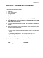
1
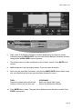
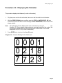
C844 Upright Cycle
C844 Bicycle
Warning: This service manual is for use by Precor trained service providers only.
If you are not a Precor Trained Servicer, you must not attempt to service any Precor Product;
Call your dealer for service.
This document contains information required to perform the majority of troubleshooting, and
replacement procedures required to repair and maintain this product.
This document contains general product information, software diagnostic procedures (when
available), preventative maintenance procedures, inspection and adjustment procedures,
troubleshooting procedures, replacement procedures and electrical block and wiring diagrams.
To move directly to a procedure, click the appropriate procedure in the bookmark section to the
left of this page. You may “drag” the separator bar between this page and the bookmark section
to change the size of the page being viewed.
© 2003 Precor Incorporated
Unauthorized Reproduction and Distribution Prohibited By Law
Page 1
C844 Upright Cycle
Section One - Things You Should Know
Right, Left, Front, and Back Conventions
In this manual, right, left, front, and back are from the perspective of a user sitting on the C844,
facing the display enclosure.
Warning and Caution Statements and General Safety Guidelines
Warning statements indicate a particularly dangerous activity. Warning statements you will find in
this manual include:
•
To remove power from the C844, the power cord must be disconnected from the wall outlet.
Always ensure that the C844 is unplugged from the wall outlet when you inspect or adjust the
C844, or when you isolate, remove, or replace a C844 component.
•
Removing the covers exposes high voltage components and potentially dangerous
machinery. Exercise extreme caution when you perform maintenance procedures with the
hood removed.
•
During service operations you will be very close to moving machinery and high voltage
components. When you perform maintenance procedures with the covers removed, remove
jewelry (especially from ears and neck), tie up long hair, remove neck ties, and do not wear
loose clothing.
•
Exercise caution when touching any wire or electrical component during C844 operation.
•
The flywheel is very heavy. Be prepared for the weight of the flywheel when it comes off of
the flywheel shaft.
Caution statements are intended to prevent damage to the C844 as a result of the current
activity. Caution statements included in this manual are listed below:
•
Notice the orientation notch on the PROM (U3). These components must be positioned with
the same notch orientation.
•
When it is necessary to lift the C844, ensure that the C844 has adequate support. Do not lift
the C844 by the front cross-member.
Safety guidelines you should know and follow include:
•
Read the owner’s manual and follow all operating instructions.
•
Visually check the C844 before beginning service or maintenance operations. If it is not
completely assembled or is damaged in any way, exercise extreme caution while operating
Page 2
C844 Upright Cycle
•
and checking the C844.
When operating the C844, do not wear loose clothing. Do not wear shoes with heels or
leather soles. Check the soles of your shoes and remove any embedded stones. Tie long hair
back.
•
Do not rock the unit. Do not stand or climb on the handlebars, display enclosure, or cover.
•
Do not set anything on the handlebars, display enclosure, or cover. Never place liquids on
any part of the C844.
•
To prevent electrical shock, keep all electrical components, such as the power cord and
circuit breaker away from water and other liquids.
•
Do not use accessory attachments that are not recommended by the manufacturer, such
attachments might cause injuries.
General Information
For the latest exploded view, part number and part pricing information, visit the Precor dealer
website at “www.precor.com/Dealer.
Page 3
C844 Upright Cycle
Required Tools and Equipment
The following is a summary of the tools and equipment that may be required when you service a
Precor C844 Upright Cycle.
Tools
Phillip and flat-head screwdrivers
Standard and metric allen wrench set
Open-end wrench set
Socket wrench set
Chip puller
Rubber mallet
Snap ring pliers
Torque wrench
Equipment
Anti-static kit
Digital multimeter
Supplies
Cable ties
Page 4
C844 Upright Cycle
Procedure 2.1 - Performing C844 Cycle Diagnostics
This procedure tests or displays the following:
•
•
•
•
•
•
•
Display Array
Seven Segment Displays
Baseline Resistance
Software Revision Number
Heart Rate Diagnostic
Power Bits
Keypad Test
1.
Plug the power cord into the wall outlet, then turn on the cycle with the ON/OFF switch.
2.
With the PRECOR C844 banner scrolling, press the STOP, WORK LEVEL UP and WORK
LEVEL DOWN keys simultaneously.
3.
Verify that the entire left display window illuminates, then two diagonal lines sweep across
the display.
4.
Watch the electronic display as the LED test progresses. This test is programmed to display
the following LED illumination sequence:
a. Every LED on the left display window illuminates simultaneously;
b. Horizontal, vertical, and diagonal lines of illuminated LED’s sweep across the left display
window;
c. The right display windows illuminate, then decrement from 8.8.8.8 to 0.0.0.0;
d. The function LED’s illuminate simultaneously and then extinguish; and
e. Each function LED illuminates separately and then extinguishes.
5.
If you do not observe the LED illumination sequence described in the previous steps . . .
THEN . . .
Replace the upper PCA as described
in Procedure 7.1.
OTHERWISE . . .
Continue with the next step.
Page 5
C844 Upright Cycle
6.
Make a note of the Baseline Resistance numbers displayed on the electronic console.
Individually press the WORK LEVEL keys and verify that the Baseline Resistance numbers
change as the WORK LEVEL keys are pressed.
7.
The software version number is displayed on the electronic console. Press ENTER, then
release.
8.
HArt is displayed in the right display window. Put on the heart rate monitor.
9.
While using the Heart Rate Transmitter, verify that the HEART RATE indicator blinks in time
with your heart beat and the heart rate information displayed is correct . . .
THEN . . .
Diagnostic software HArt mode checks
correctly; continue with the next step.
OTHERWISE . . .
Refer to the Smart Rate System
Service and Maintenance Manual.
10. Press ENTER, then release. The power bits is displayed on the electronic console. Press
ENTER, then release.
Page 6
C844 Upright Cycle
Note:
Seven dots are displayed in the center of the left window.
As you press each key listed in Step 11, the column of the left display window corresponding to
the key pressed should illuminate. When you release each key, the column of light should be
replaced by a single dot.
11. Press each key listed:
BLANK
ENTER
BLANK
STOP
WORK LEVEL UP
WORK LEVEL DOWN
12. If the appropriate sections of the left display window illuminated when the corresponding
keys were pressed . . .
THEN . . .
The keypad test passed successfully;
continue with the next step.
OTHERWISE . . .
Replace the upper PCA as described
in Procedure 7.1.
13. Press ENTER and WORK LEVEL UP to return to the PRECOR C844 banner.
Page 7
C844 Upright Cycle
Procedure 2.2 - Displaying the Odometer
This procedure displays total distance (in miles or kilometers).
1.
Plug the power cord into the wall outlet, then turn on the bike with the circuit breaker.
2.
With the PRECOR C844 banner scrolling, press the STOP and WORK LEVEL UP keys
simultaneously and hold them until the message CYCLE ODOMETER scrolls across the left
display window.
Note:
3.
The right display window displays total miles or kilometers on the cycle
(see
Diagram 2-2). The top display window shows the most significant bits of the number; the
lower display window shows the least significant bits of the number. The number
displayed is 102,187,723 (in miles or kilometers).
Press ENTER twice to return to the User ID prompt.
Diagram 2-2. Odometer Reading For the C844 Cycle
0 0 0 1
0 2 1 8
7 7 2 3
Page 8
C844 Upright Cycle
Procedure 2.3 - Selecting Club Settings
This procedure allows the modification of the following settings:
•
•
•
U. S. Standard/Metric
Line Voltage Selection
Get Max Workout Time
1.
Plug the power cord into the wall outlet, then turn on the cycle with the ON/OFF switch.
2.
With the PRECOR C844 banner scrolling, press the QUICKSTART and WORK LEVEL ▲
keys simultaneously. Across the left display window scrolls either the banner U. S.
Standard or the banner Metric.
3.
If you wish to change the measurement standard . . .
THEN . . .
Use the UP or DOWN keys to toggle
to an alternate measurement standard;
then continue with the next step.
OTHERWISE . . .
Continue with the next step.
4.
Press ENTER, then release. The line voltage currently selected is displayed on the left
display window.
5.
If you wish to toggle to the alternate line voltage. . .
THEN . . .
Use the UP or DOWN keys to toggle
to the alternate line voltage; then
continue with the next step.
OTHERWISE . . .
Continue with the next step.
6.
Press ENTER, then release. The maximum workout time is displayed on the left display
window.
7.
If you wish to change the maximum workout time . . .
Page 9
C844 Upright Cycle
THEN . . .
Use the UP or DOWN keys to select
the new maximum workout time;
then continue with the next step.
8.
OTHERWISE . . .
Continue with the next step.
Press ENTER, then release to return to the C844 Cycle banner.
Page 10
C844 Upright Cycle
Procedure 2.4 - Documenting Software Problems
When a problem is found with either the software or upper or lower PCA’s, record the information
listed below. If you isolated the problem to either the PROM, upper PCA, or lower PCA, include
the information you recorded with the malfunctioning PROM or PCA when you ship it to Precor
Customer Support.
When a problem occurs, record the following information:
•
Model and serial number
Note: The model serial number is located on the bottom of the lower crossbeam.
•
•
Software version number
Odometer reading
Note:
Determine the version number of the PROM mounted on the upper PCA as described in
Procedure 2.1.
•
User and program number running when the problem occurred
•
A description of:
a. What happened or failed to happen
b. The action taken by the user just before the problem occurred
c. Problem related information (such as how far into the program the problem occurred, the
work level being used when the problem occurred, etc.)
•
The frequency of occurrence
Page 11
C844 Upright Cycle
Section Three - Preventive Maintenance
Preventive maintenance measures are either scheduled or unscheduled. Scheduled preventive
maintenance activities are included here so that you are aware of preventive measures
performed on a regular basis.
Regular Preventive Maintenance (Owner)
Cleanliness of the cycle and its operating environment will keep maintenance problems and
service calls to a minimum. Precor recommends performing the following preventive
maintenance schedule.
At the End of Each Day
•
Wipe the pedals with a damp cloth.
Every Week
•
Wipe the surface of the electronic console with a barely-damp sponge or soft cloth. Dry with
a clean towel.
CAUTION
Keep water away from electronic components to prevent shock.
On-Site Preventive Maintenance (Service Technician)
Perform the following preventive maintenance tasks each time you are called to service a C844:
•
Check the LED’s mounted on the upper PCA and the function keys displayed on the electronic console by performing Procedure 2.1.
•
Measure the gap between the flywheel and the magnets as described in
Procedure 5.1.
•
Visually examine all wires and check connectors and wire connections. Secure connections
and replace wiring as necessary.
•
When the covers are removed, visually inspect the lower ribbon cable and the part of the
upper ribbon cable that is not inside the column. If either ribbon cable is torn or damaged,
replace it as described in Procedure 7.7.
Page 12
C844 Upright Cycle
Section Four - Checking Unit Operation
This section provides you with a quick method of checking cycle operation. Check the operation
of the C844 Cycle at the end of most maintenance procedures.
Procedure
1.
Plug the power cord into the wall outlet, then turn on the bike with the circuit breaker.
2.
If the display does not illuminate refer to procedures 6.3 0r 6.4.
3.
When the PRESS ENTER FOR PROGRAMS prompt appears, press QUICK START.
4.
Select Work Level 1 and press ENTER.
5.
Operate the C844 for 4–5 minutes. As you operate the cycle, concentrate on the resistance
and operating sounds of the unit. Be on the alert for unusual rubbing, hitting, grinding or
squeaking noises.
6.
Press the WORK LEVEL UP key until you reach Work Level 5. Operate the cycle for
another 2–3 minutes.
7.
If the resistance of the cycle does not change or the operation of the cycle feels inconsistent
compared with Work Level 1 . . .
THEN . . .
Refer to procedures 6.5 and 6.6
OTHERWISE . . .
Continue with the next step.
8.
Press the WORK LEVEL UP key until you reach Work Level 10. Operate the cycle for
another 2–3 minutes.
9.
If the resistance of the cycle does not change or the operation of the cycle feels inconsistent
with Work Levels 1 and 5 . . .
THEN . . .
Refer procedures 605 and 6.6
OTHERWISE . . .
Continue with the next step.
10. Check the LED’s mounted on the upper PCA and the function keys displayed on the electronic console by performing Procedure 2.1.
11. If the keys do not respond appropriately, refer to procedure 6.2.
Page 13
C844 Upright Cycle
Procedure 5.1 - Inspecting and Adjusting the Gap Between
the Magnets and Flywheel
WARNING
Always turn off the C844 with the ON/OFF switch and unplug the power cord from the wall
outlet before you service the cycle.
Procedure
1.
Place the C844 Cycle on its front end. Remove the pan from the base of the cycle.
2.
Loosen one of the magnet assemblies.
Note:
Do not loosen the screws that secure the magnet assembly too much. Although you
must be able to move the magnet assembly along the adjustment slots, the assembly
must stay in place after it is moved.
3.
Place a .050" feeler gauge between the flywheel and each of the magnet coils that make up
the magnet assembly.
4.
Choose one. If the feeler gauge does not fit snugly . . .
THEN . . .
Continue with the next step.
OTHERWISE . . .
Skip to Step 6.
5.
Slide the magnet assembly along its adjustment slots until the feeler gauge fits snugly
between the flywheel and the magnet coil.
6.
Tighten the screws that secure the magnet assembly to the frame (see Diagram 5-1).
7.
Repeat Steps 2 through 4 for the remaining magnet assembly.
8.
Install the pan on the base of the cycle. Return the cycle to its upright position.
9.
Check the operation of the C844 as described in Section Four.
Page 14
C844 Upright Cycle
Diagram 5-1
Adjusting the gap between the flywheel and magnet assembly
Page 15
C844 Upright Cycle
Procedure 5.2 - Measuring the Resistance of a Magnet
WARNING
Always turn off the C844 with the ON/OFF switch and unplug the power cord from the wall
outlet before you service the cycle.
Procedure
1.
Place the C844 Cycle on its front end. Remove the pan from the base of the cycle.
2.
Set the ohmmeter to a range that will conveniently read 125 ohms.
Caution
Remove power from the C844 before you measure magnet resistance.
3.
Remove the wires from the terminals on the top magnet. Measure the resistance between
the two terminals.
Note:
The resistance of the magnets will be higher than optimum (90 - 110 ohms) when they are
warm. Take resistance measurements when the magnets are at room temperature.
4.
If the resistance measures significantly less than 90 ohms or significantly more than 110
ohms . . .
THEN . . .
Replace the magnet as described
in Procedure 7.13.
OTHERWISE . . .
Connect the wires to the magnet.
Then continue with the next step.
Note:
The C844 magnet cable assembly is shown in Diagram 5-2.
5.
Repeat Steps 3 and 4 for the remaining magnets.
6.
Install the pan on the base of the cycle. Return the cycle to its upright position.
7.
Check the operation of the C844 as described in Section Four.
Page 16
C844 Upright Cycle
Diagram 5.2 C844 Magnet Wiring
Page 17
C844 Upright Cycle
Procedure 5.3 - Inspecting and Adjusting the Gap Between
Upper and Lower Couplers
WARNING
Always turn off the C844 with the ON/OFF switch and unplug the power cord from the wall outlet
before you service the cycle.
Procedure
1.
Remove the upright covers from the pedestal weldment.
2.
Place a .060" feeler gauge between the upper and lower couplers.
3.
If the feeler gauge fits snugly . . .
THEN . . .
OTHERWISE . . .
Remove the feeler gauge and rotate
Adjust the gap between the couplers
the couplers about 90 degrees.
as described in the following steps.
Re-check the gap between the couplers.
Rotate the couplers and check the gap
until you you have checked the gap between
the couplers at four different spots. Skip to
Step 8.
4.
Remove the set screw that secures the upper coupler to the gear box (see
Diagram 5-3). If necessary, remove the old loc-tite from the set screw.
5.
Adjust the position of the coupler on the gear box shaft until the feeler gauge fits snugly
between the upper and lower couplers.
6.
Place a drop of blue loc-tite on the set screw removed in Step 4. Install the set screw into
the upper coupler.
7.
Rotate the couplers about 90 degrees, then return to Step 2.
8.
Install the upright covers on the pedestal weldment.
9.
Check the operation of the C844 as described in Section Four.
Page 18
C844 Upright Cycle
Diagram 5.3 The Upper and Lower Couplers
Page 19
C844 Upright Cycle
Procedure 6.1 - Troubleshooting the Lower and Upper Ribbon
Cables
WARNING
Always turn off the C844 with the ON/OFF switch and unplug the power cord from the wall outlet
before you service the cycle.
Troubleshooting the Upper Ribbon Cable
1.
Remove the upright covers from the pedestal weldment.
2.
Attach an anti-static wrist strap to your arm, then connect the ground lead of the wrist strap
to the C844 frame.
3.
Disconnect the upper ribbon cable from the upper PCA.
4.
Disconnect the upper ribbon cable from the lower ribbon cable.
5.
Connect the spare ribbon cable between the upper PCA and the lower ribbon cable.
6.
Check the operation of the cycle as described in Section Four.
7.
If the cycle operated correctly when the spare ribbon cable was installed . . .
THEN . . .
The original upper ribbon cable is bad;
install a new cable as described in
Procedure 7.7.
OTHERWISE . . .
The original upper ribbon cable is not
defective; continue with the next step.
8.
Disconnect the spare ribbon cable from the upper PCA and the lower ribbon cable.
9.
Reconnect the original upper ribbon cable.
10. Place the C844 Cycle on its front end. Remove the pan from the base of the cycle.
11. Disconnect the lower ribbon cable from the lower PCA.
12. Disconnect the lower ribbon cable from the upper ribbon cable.
13. Connect the spare ribbon cable between the lower PCA and the upper ribbon cable.
14. Check the operation of the cycle as described in Section Four.
Page 20
C844 Upright Cycle
15. If the cycle operated correctly when the spare ribbon cable was installed . . .
THEN . . .
The original lower ribbon cable is bad;
install a new cable as described in
Procedure 7.7.
OTHERWISE . . .
The original lower ribbon cable is not
defective; continue with the next step.
16. Disconnect the spare ribbon cable from the lower PCA and the upper ribbon cable.
17. Connect the original lower ribbon cable to the upper PCA.
18. Install the pan to the base of the cycle. Return the cycle to its upright position.
19. Connect the upper ribbon cable to the lower ribbon cable.
20. Remove the ground lead of the wrist strap from the C844 frame, then remove the wrist strap
from your arm.
21. Install the upright covers on the pedestal weldment.
22. Check the operation of the cycle as described in Section Four.
Page 21
C844 Upright Cycle
Procedure 6.2 - Troubleshooting the Keypad and Upper PCA
If the function keys on the electronic console are unresponsive, the problem may be either the
upper PCA or keypad. This troubleshooting procedure gives you the information you need to
determine which of these components is malfunctioning.
Procedure
1.
Set the circuit breaker in the “off” position.
WARNING
Before continuing with this procedure, review the Warning and Caution statements listed in
Section One of the Residential Treadmill Service Manual.
2.
Remove the screws that secure the upper display assembly to the upper handrail. Carefully,
pull some excess interconnect cable out from the targa upright. Rotate the display housing,
so that the rear of the upper PCA is facing upward, and set the display housing on the upper
handrail.
3.
Attach the wrist strap to your arm, then connect the ground lead of the wrist strap to the
treadmill frame.Set the voltmeter to a range that will conveniently read +6 Vdc.
U13
Diagram 6.2 - Upper PCA Component Layout
U3
26
RN4
2
J2
J1
25
RN5
1
J4
J5
4.
Set the voltmeter to a range that will conveniently read +6 Vdc.
5.
Set the circuit breaker in the “on” position.
6.
Use a DVM, set for DC volts, and read between pin 6 of J3 and the each of the pins in Table
6.1 (no keys pressed) and Table 6.2 (with the appropriate key pressed)...
Page 22
C844 Upright Cycle
Table 6.1 - Voltage Test Points (Function Keys Not Pressed)
Place the positive lead of the
voltmeter on...
Pin 3 of J3
Pin 7 of J3
Pin 8 of J3
Pin 9 of J3
Pin 10 of J3
The voltmeter should read...
5 Vdc ± 500 mVdc
5 Vdc ± 500 mVdc
5 Vdc ± 500 mVdc
5 Vdc ± 500 mVdc
5 Vdc ± 500 mVdc
Table 6.2 - Voltage Test Points (Function Keys Pressed)
Place the positive
voltmeter lead on...
Pin 3 of J3
Pin 7 of J3
Pin 8 of J3
Pin 9 of J3
Pin 10 of J3
At the display
enclosure, press...
ENTER
STOP
WORK LEVEL DOWN
WORK LEVEL UP
QUICK START
The voltmeter should
read between...
0 Vdc and 500 mVdc
0 Vdc and 500 mVdc
0 Vdc and 500 mVdc
0 Vdc and 500 mVdc
0 Vdc and 500 mVdc
7.
If the voltage readings match those listed in Tables 6.1 and 6.2 and one or more keys do not
function, replace the upper PCA.
8.
If the voltage readings in Table 6.1 are incorrect, disconnect the keypad cable from the key
pad connector and repeat the voltage measuremnts in 6.1. If the voltage readings are now
correct, replace the display housing (keypad). If the voltage readings are still incorrect,
replace the upper PCA.
9.
If the voltage readings in Table 6.1 are correct and one or more voltage readings in Table
6.2 are incorrect, replace the display housing (keypad).
10. Set the circuit breaker in the “off” position.
11. If necessary, carefully re-connect the keypad cable to the keypad connector.
12. Remove the ground lead of the wrist strap from the treadmill frame, then remove the wrist
strap from your arm.
13. Position the display enclosure on the display plate. Install the screws that secure the display
enclosure to the display plate.
14. Check the operation of the treadmill as described in Section Three of this appendix.
Page 23
C844 Upright Cycle
Procedure 6.3 - Display does not Illuminate (120 VAC Units)
Warning
Hazardous voltages will be tested in the following procedures. Exercise extreme caution when
performing these procedures.
Note:
Unless otherwise specified the AC voltage referenced in the following procedures will be AC line
voltage and should measure 120 VAC ± 15 VAC.
1.
Remove the C844 line cord from the AC outlet. Using an AC voltmeter, test the AC wall outlet for AC voltage. If the AC voltage is incorrect or missing, check the AC service circuit
breaker and/or AC service wiring.
2.
Remove the AC line cord from the C844 AC input module. Using an ohmmeter, test the
three line cord conductors for continuity. Each conductor should read 1Ω or less. If any of
the three line cord conductors do not read correctly, replace the line cord.
3.
Plug the AC line cord into the C844 AC input module. Plug the AC line cord into AC wall
outlet. Using an AC voltmeter, check the AC voltage between the brown and blue wires on
the AC input module. If the AC voltage is incorrect or missing, unplug the AC line cord from
the AC wall outlet and remove the fuse from the AC input module. Using an ohmmeter,
check the fuse for continuity. If the fuse does not read 1Ω or less, replace the fuse. Plug
the AC line cord into the AC wall outlet, and test the operation of the C844.
4.
Set the C844 on/off switch in the on position. Using an AC voltmeter, check between the
blue and brown wires on the load side of the on/off switch (terminals 1 & 4). If the AC
voltage is incorrect or missing, replace the on/off switch.
5.
Using an AC voltmeter, check the AC voltage at pins 1 & 2 of plug P4 on the lower PCA. If
the AC voltage is incorrect or missing check the wiring between the on/off switch and lower
PCA.
6.
Using an AC voltmeter, check the AC voltage at pins 8 & 9 of plug P5 on the lower PCA. If
the AC voltage is incorrect or missing, replace the lower PCA.
7.
Using an AC voltmeter, check the AC voltage at pins 2 & 5 of plug P5 on the lower PCA.
The voltage should be approximately 9 VAC. If the voltage is significantly high, low or
missing replace the stepdown transformer assembly.
8.
If you have performed all of the previous tests and the green light emitting diode (LD1) on
the lower PCA is not lit, replace the lower PCA.
9.
Using a DC voltmeter, measure the voltage between TP1 (+) and TP2 (-) on the lower PCA.
The voltage should measure 6 VDC ± .25 VDC. If the DC voltage is incorrect or missing,
replace the lower PCA.
Page 24
C844 Upright Cycle
10. Using a DC voltmeter, measure the voltage between terminals 1 and 26 of the ribbon cable
connector (J2) on the upper PCA. The voltage should measure 6 VDC ± .25 VDC. If the DC
voltage is incorrect or missing, check the ribbon cable connections at the lower and upper
PCA’s. Check the ribbon cable for cut or frayed wires. If necessary replace the ribbon
cable.
11. If the voltage in step 8 measured 6 VDC ± .25 VDC and the upper display is not illuminated,
be sure that the U3 prom is correctly installed and firmly seated in its socket on the upper
PCA. If the prom is correctly installed, replace the UPCA.
12. If you have performed all of the previous tests and have not been able to locate the trouble,
call Precor customer support.
Page 25
C844 Upright Cycle
Procedure 6.4 - Display does not Illuminate (240 VAC Units)
Warning
Hazardous voltages will be tested in the following procedures. Exercise extreme caution when
performing these procedures.
Note:
Unless otherwise specified the AC voltage referenced in the following procedures will be AC line
voltage and should measure between approximately 195 VAC and approximately 245 VAC.
1.
Remove the C844 line cord from the AC outlet. Using an AC voltmeter, test the AC wall outlet for AC voltage. If the AC voltage is incorrect or missing, check the AC service circuit
breaker and/or AC service wiring.
2.
Remove the AC line cord from the C844 AC input module. Using an ohmmeter, test the
three line cord conductors for continuity. Each conductor should read 1Ω or less. If any of
the three line cord conductors do not read correctly, replace the line cord.
3.
Plug the AC line cord into the C844 AC input module. Plug the AC line cord into AC wall
outlet. Using an AC voltmeter, check the AC voltage between the brown and blue wires on
the AC input module. If the AC voltage is incorrect or missing, unplug the AC line cord from
the AC wall outlet and remove the fuse from the AC input module. Using an ohmmeter,
check the fuse for continuity. If the fuse does not read 1Ω or less, replace the fuse. Plug
the AC line cord into the AC wall outlet, and test the operation of the C844.
4.
Set the C844 on/off switch in the on position. Using an AC voltmeter, check between the
blue and brown wires on the load side of the on/off switch (terminals 1 & 4). If the AC
voltage is incorrect or missing, replace the on/off switch.
5.
Using an AC voltmeter, check the AC voltage at the output side of the input line filter. If the
AC voltage is incorrect or missing, replace the input line filter.
6.
Using an AC voltmeter, check the AC voltage at pins 4 & 7 of plug P5 on the lower PCA. If
the AC voltage is incorrect or missing, replace the lower PCA.
7.
Using an AC voltmeter, check the AC voltage at pins 2 & 5 of plug P5 on the lower PCA.
The voltage should be approximately 9 VAC. If the voltage is significantly high, low or
missing replace the stepdown transformer assembly.
8.
If you have performed all of the previous tests and the green light emitting diode (LD1) on
the lower PCA is not lit, replace the lower PCA.
9.
Using a DC voltmeter, measure the voltage between TP1 (+) and TP2 (-) on the lower PCA.
The voltage should measure 6 VDC ± .25 VDC. If the DC voltage is incorrect or missing,
replace the lower PCA.
10. Using a DC voltmeter, measure the voltage between terminals 1 and 26 of the ribbon cable
Page 26
C844 Upright Cycle
connector (J2) on the upper PCA. The voltage should measure 6 VDC ± .25 VDC. If the DC
voltage is incorrect or missing, check the ribbon cable connections at the lower and upper
PCA’s. Check the ribbon cable for cut or frayed wires. If necessary replace the ribbon
cable.
11. If the voltage in step 8 measured 6 VDC ± .25 VDC and the upper display is not illuminated,
be sure that the U3 prom is correctly installed and firmly seated in it’s socket on the upper
PCA. If the prom is correctly installed, replace the UPCA.
12. If you have performed all of the previous tests and have not been able to locate the trouble,
call Precor customer support.
Page 27
C844 Upright Cycle
Procedure 6.5 - The RPM Display is Incorrect
1.
Plug the C844 line cord into an AC outlet and set the on/off switch in the on position. Use
the “Quick Start” key to enter the manual program. Using a watch or clock as reference,
pedal the bike at a rate of one revolution per second. The second window on the right of the
display should indicate approximately 60 RPM. If the RPM reading is significantly high or
low go to step 5. If the RPM reading is zero continue with step 2.
2.
Rotate the flywheel so that the magnet mounted on the flywheel is 180° away from the reed
switch mounted on the frame. Using a DC voltmeter, measure the voltage between pins 1 &
2 of P6 on the lower PCA. The voltage should read approximately 6 VDC. If the voltage is
correct skip to step 3. If the voltage is significantly lower than 6 VDC, disconnect the P6
plug from the lower PCA. Measure the voltage at pins 1 & 2 of P6 on the lower PCA. If the
voltage is still significantly lower than 6 VDC replace the lower PCA. If the voltage is correct
with P6 disconnected, replace reed switch
3.
Using a DC voltmeter measure the voltage between pins 1 & 2 of P6 on the lower PCA.
Carefully rotate the flywheel. When the magnet (mounted in the flywheel) passes the reed
switch (mounted on the frame) the voltage should toggle between approximately 6 VDC to
approximately 0 VDC. After the magnet passes the reed switch, the voltage should toggle
back to approximately 6 VDC.
4.
If the voltage in step 3 does not toggle, remove the flywheel. Using a known good magnet,
pass it near the reed switch. The voltage should toggle as described in step 3. If the
voltage toggles, replace the magnet. If the voltage does not toggle, replace the reed switch.
Test the C844 as in step 1, if the RPM reading is still 0, call Precor customer support. If the
RPM reading is significantly high or low, proceed with step 5.
5.
Incorrect RPM readings can result from either a weak magnet or a defective reed switch.
There are no good test procedures to test for intermittent operation. The simplest procedure
is to replace the magnet or reed switch one at a time and test the C844 operation. Replace
either component as appropriate. If neither component corrects the problem, call Precor
customer support.
Page 28
C844 Upright Cycle
Procedure 6.6 - No or Incorrect Pedaling Resistance
1.
If the display is not illuminated, go to Procedure 6.3 (120 VAC units) or Procedure 6.4 (240
VAC units).
2.
Enter the “manual” program and set the work level at “level 10”. Pedal the bike and confirm
that there is no resistance or that the resistance is abnormally low.
Note:
The C844 will time out and remove power from the magnets in a short period of time. Slowly
rotate the flywheel while taking the magnet voltage reading (step 3) to ensure that the C844 has
not timed out.
3.
With the work level set at “level 10”, use a DC voltmeter to measure the voltage between
terminals 1 & 2 of P3 on the lower PCA. The voltage should measure approximately 87
Vdc.
4.
If the voltage is missing or significantly lower than 87 Vdc, continue with step 6.
5.
If the voltage is approximately 87 Vdc, but there is no resistance, set the on/off switch in the
off position. Use wiring diagram 5.2 on page 5-5 to verify that the magnets are correctly
wired. If the wiring of one or more of the magnets is reversed, the resistance will not be
correct.
6.
Remove the P3 plug from the lower PCA and measure the voltage as in step 3. Perform the
measurement on pins 1 & 2 of the P3 connector on the lower PCA. The voltage should
measure approximately 87 Vdc. If the the voltage is missing or significantly low, replace the
lower PCA. If the voltage is approximately 87 Vdc, continue with step 7.
7.
One at a time remove the wiring from one of the four magnets. Using an ohmmeter,
measure the resistance of the magnet. The resistance should be approximately 95Ω. If the
resistance is significantly low, replace the magnet assembly. Using an ohmmeter, measure
the resistance between each magnet terminal and frame ground. The resistance should be
infinite. If the reading is not infinite, replace the magnet assembly.
8.
Repeat the procedure in step 7 with each of the other three magnets.
9.
If you have performed all of the previous tests and have not been able to locate the trouble,
call Precor customer support.
Page 29
C844 Upright Cycle
Procedure 7.1 - Replacing the Display Enclosure or Upper
PCA
Anti-static kits (part number 20024-101) can be ordered from Precor.
WARNING
Always turn off the C844 with the ON/OFF switch and unplug the power cord from the wall outlet
before you service the cycle.
1.
Remove the screws that secure the upper display module assembly to the upper frame
member.
CAUTION
When you perform the next step, tape the ribbon cable to the C844 Transport to prevent it from
falling into the upper frame member.
2.
3.
4.
Attach the wrist strap to your arm, then connect the ground lead of the wrist strap to the
C844 frame.
Disconnect the ribbon cable from the upper PCA (see Diagram 7-1).
Remove the screws that secure the display enclosure to the display plate.(see Diagram 7-1)
Diagram 7-1 Replacing the Display Enclosure or Upper PCA
Page 30
C844 Upright Cycle
5.
If you are going to re-install the display enclosure without replacing the upper PCA . . .
THEN . . .
Skip to Step 9.
OTHERWISE . . .
Continue with the next step.
6.
Carefully disconnect the keypad ribbon cable from the upper PCA.
7.
Remove the screws that secure the upper PCA to the display enclosure. Set aside the
defective upper PCA for eventual shipment to Precor Customer Support.
Note:
When you package the upper PCA, document the problem as described in Documenting
Software Problems.
8.
Position the upper PCA at its mounting location on the display enclosure. Install the screws
that secure the upper PCA to the display enclosure.
9.
Line up the blank place on the end of the keypad ribbon cable with the blank pin position on
the keypad connector. Place a full twist in the end of the keypad ribbon cable, then carefully
connect it to the upper PCA.
10. Connect the ribbon cable to the upper PCA.
11. Position the upper display module on the upper frame member. Install the screws that
secure the display module to the upper frame member.
12. Remove the ground lead of the wrist strap from the C844 frame, then remove the wrist strap
from your arm.
13. Position the display plate on the display enclosure. Install the screws that secure the display
enclosure to the display plate.
14. Check the operation of the C844 as described in Section Four.
Page 31
C844 Upright Cycle
Procedure 7.2 - Replacing the PROM
WARNING
Always turn off the C844 with the ON/OFF switch and unplug the power cord from the wall outlet
before you service the cycle.
1.
Remove the screws that secure the upper display module assembly to the upper frame
member.
CAUTION
When you perform the next step, tape the ribbon cable to the C844 to prevent it from falling into
the upper frame member.
2.
Attach the wrist strap to your arm, then connect the ground lead of the wrist strap to the
C844 frame.
3.
Disconnect the ribbon cable from the upper PCA.
4.
Remove the screws that secure the display enclosure to the display plate.
5.
Carefully disconnect the ribbon cable keypad from the connector on the upper PCA.
6.
Remove the screws that secure the upper PCA to the display enclosure.
Replacing the PROM
Keep the new PROM in its protective packaging until you are ready to insert it into the chip
socket.
Caution
Notice the orientation notch on the PROM (see Diagram 7-2). The new PROM must be
positioned with the same notch orientation. Replacing the PROM backwards will destroy the
PROM.
7.
Using the chip puller, remove the PROM (U3) from the upper PCA.
8.
Carefully insert the new PROM with the correct software version number in the chip socket.
Take care not to bend the legs of the PROM.
Note:
The software version number is labeled on the PROM.
Page 32
C844 Upright Cycle
Diagram 7.2 Upper PCA Component Layout
9.
Position the upper PCA at its mounting location on the display enclosure. Install the screws
that secure the upper PCA to the display enclosure.
10. Line up the blank place on the end of the keypad ribbon cable with the blank pin position on
the keypad connector. Place a full twist in the end of the keypad ribbon cable, then carefully
connect it to the to the upper PCA.
11. Connect the ribbon cable to the upper PCA.
12. Turn the display enclosure so that the display label is facing up.
13. Remove the ground lead of the wrist strap from the C844 frame, then remove the wrist strap
from your arm.
14. Check the operation of the C844 as described in Section Four.
15. If the C844 operates correctly . . .
THEN . . .
Continue with the next step.
OTHERWISE . . .
Replace the upper PCA as described
in Procedure 7.1.
16. Attach the anti static wrist strap to your arm, then connect the ground lead of the wrist strap
to the C844 frame.
17. Remove the ribbon cable from the upper PCA.
18. Position the display plate on the display enclosure. Install the screws that secure the display
enclosure to the display plate.
19. Connect the ribbon cable to the upper PCA.
Page 33
C844 Upright Cycle
20. Remove the ground lead of the wrist strap from the C844 frame, then remove the wrist strap
from your arm.
21. Position the upper display module on the upper frame member. Install the screws that
secure the display module to the upper frame member.
22. Check the operation of the C844 as described in Section Four.
Page 34
C844 Upright Cycle
Procedure 7.3 - Replacing the Lower PCA
WARNING
Always turn off the C844 with the ON/OFF switch and unplug the power cord from the wall outlet
before you service the cycle.
1.
Place the C844 Cycle on its front end. Remove the pan from the base of the cycle.
2.
Attach the anti static wrist strap to your arm, then connect the ground lead of the wrist strap
to the C844 frame.
Note:
Refer to the wiring diagram shown in Diagram 7-3. Always mark all wires before disconnecting, to
ensure quick accurate replacement!
3.
Disconnect the cables from the lower PCA.
4.
Remove the fasteners that secure the lower PCA to the cycle frame.
5.
Hold the replacement lower PCA against the cycle frame. Install the fasteners that secure
the lower PCA to the frame.
6.
Connect the cables you disconnected in Step 3.
7.
Remove the ground lead of the wrist strap from the C844 frame, then remove the wrist strap
from your arm.
8.
Install the pan on the base of the cycle. Return the cycle to its upright position.
9.
Check the operation of the C844 as described in Section Four.
Page 35
C844 Upright Cycle
Diagram 7-3 C844 Wiring Diagram (120Vac Units)
Page 36
C844 Upright Cycle
Procedure 7.4 - Replacing the ON/OFF Switch
WARNING
Always turn off the C844 with the ON/OFF switch and unplug the power cord from the wall outlet
before you service the cycle.
1.
Place the C844 Cycle on its front end. Remove the pan from the base of the cycle.
2.
Disconnect the wires that are connected to the ON/OFF switch.
3.
Depress the mounting tabs and push the ON/OFF switch out of the base plate.
4.
Position the new ON/OFF switch at its mounting location.
5.
Connect the brown wire on the AC input module to terminal 2 of the ON/OF switch.
6.
Connect the blue wire on the AC input module to terminal 3 of the ON/OFF switch.
7.
Connect the brown wire on the lower PCA to terminal 1 of the the ON/OFF switch.
8.
Connect the blue wire on the lower PCA to terminal 4 of the the ON/OFF switch.
9.
Install the pan on the base of the cycle. Return the cycle to its upright position.
10. Plug the power cord into the power entry module.
11. Check the cycle operation as described in Section Four.
Page 37
C844 Upright Cycle
Procedure 7.5 - Replacing the AC Input Module
WARNING
Always turn off the C844 with the ON/OFF switch and unplug the power cord from the wall outlet
before you service the cycle.
1.
Place the C844 Cycle on its front end. Remove the pan from the base of the cycle.
2.
Remove the power cord from the AC input module.
3.
Disconnect the brown and blue wires from the AC input module.
4.
Remove the screw that secures the green ground wire to the cycle frame.
5.
Depress the mounting tabs and push the AC input module out of the base plate.
6.
Position the new AC input module at its mounting position.
7.
Position the green ground wire at its mounting location. Replace the screw that secures the
green ground wire to the cycle frame.
8.
Connect the brown and blue wires disconnected in Step 3 to the AC input module.
9.
Plug the power cord into the AC input module.
10. Install the pan to the base of the cycle. Return the cycle to its upright position.
11. Check the cycle operation as described in Section Four.
Page 38
C844 Upright Cycle
Procedure 7.6 - Replacing the Input Filter Assembly (240-Volt
Units Only)
WARNING
Always turn off the C844 with the ON/OFF switch and unplug the power cord from the wall outlet
before you service the cycle.
1.
Place the C844 Cycle on its front end. Remove the pan from the base of the cycle.
2.
Disconnect the wires that are connected to the input filter assembly.
3.
Remove the fasteners that secure the input filter assembly to the cycle frame.
4.
Position the new filter assembly at its mounting location.
5.
Install the connectors that secure the filter assembly to the cycle frame.
6.
Connect the wires removed in Step 2 to the new input filter assembly.
7.
Install the pan on the base of the cycle. Return the cycle to its upright position.
8.
Plug the power cord into the power entry module.
9.
Check the cycle operation as described in Section Four.
Page 39
C844 Upright Cycle
Procedure 7.7 - Replacing the Upper and Lower Ribbon
Cables
Before you install a new ribbon cable, ensure that the ribbon cable is defective as described in
Procedure 6.1.
WARNING
Always turn off the C844 with the ON/OFF switch and unplug the power cord from the wall outlet
before you service the cycle.
1.
2.
Remove the upright covers from the pedestal weldment.
Disconnect the lower ribbon cable from the upper ribbon cable (see Diagram 7-5).
Diagram 7-5 C844 Ribbon Cables
Page 40
C844 Upright Cycle
3.
Choose one:
IF . . .
You are replacing the upper ribbon
cable
You are replacing the lower ribbon
cable
THEN . . .
Continue with the next step.
Skip to Step 9.
Replacing the Upper Ribbon Cable
4.
Disconnect the ribbon cable from the upper PCA per Steps 1 through 3 of
Procedure 7.1.
5.
Tape the lower end of the new upper ribbon cable to the upper end of the original upper
ribbon cable.
6.
Pull the original upper ribbon from the bottom of the upright weldment. When the connector
of the new cable clears the upright, disconnect and discard the original ribbon cable.
7.
Connect the new upper ribbon cable to the upper PCA per Steps 10 through 13 of
Procedure 7.1.
8.
Choose one: If you are installing a new lower ribbon cable on the cycle . . .
THEN . . .
Continue with the next step.
9.
OTHERWISE . . .
Skip to Step 13.
Place the C844 Cycle on its front end. Remove the pan from the base of the cycle.
10. Disconnect the lower ribbon cable from the lower PCA.
11. Tape the upper end of the new lower ribbon cable to the lower end of the old lower ribbon
cable. Pull the cable through the cycle frame.
12. Connect the new lower ribbon cable to the lower PCA.
13. Install the pan on the base of the cycle. Return the cycle to its upright position.
14. Connect the upper and lower ribbon cables to each other.
15. Install the upright covers on the pedestal weldment.
16. Check the operation of the cycle as described in Section Four.
Page 41
C844 Upright Cycle
Procedure 7.8 - Replacing the Pedals
WARNING
Always turn off the C844 with the ON/OFF switch and unplug the power cord from the wall outlet
before you service the cycle.
1.
Use an open-end wrench to remove the right pedal from the crank arm.
Note:
The right pedal comes with reverse screw threads. When you remove the right pedal, turn the
pedal connector clockwise.
2.
Face the left side of the cycle. Use an open-end wrench to remove the left pedal from the
crank arm.
Replacing the Pedals
The pedals are marked with an R (Right) and an L (Left). When you replace the pedals, make
sure that the new pedals are mounted on the appropriate side of the cycle.
3.
Thread the right pedal connector counterclockwise onto the crank arm. Tighten the pedal
connector.
4.
Face the left side of the cycle. Thread the left pedal connector clockwise onto the crank arm.
Tighten the pedal connector.
5.
Check the operation of the cycle as described in Section Four.
Page 42
C844 Upright Cycle
Procedure 7.9 - Replacing a Crank Arm
If you are removing a crank arm, do not remove the pedal unless the pedal is worn or damaged
and must be replaced.
WARNING
Always turn off the C844 with the ON/OFF switch and unplug the power cord from the wall outlet
before you service the cycle.
1.
Using the flat-head screwdriver, remove the crank axle dress cap.
2.
Remove the bolt that secures the crank arm to the crank axle.
3.
If you are removing a crank arm because it must be replaced with a new crank
arm, remove the pedal from the crank arm as described in Procedure 7.8.
4.
Place the crank arm on the crank axle.
Note:
The right and left crank arms must be pointing in opposite directions
5.
Replace the bolt that secures the crank arm to the crank axle. Torque to 45–50
inch-pounds.
6.
Mount the pedal removed from the original crank arm on the new assembly as described in
Procedure 7.8.
7.
Check the operation of the cycle as described in Section Four.
Page 43
C844 Upright Cycle
Procedure 7.10 - Replacing the Gear Box
WARNING
Always turn off the C844 with the ON/OFF switch and unplug the power cord from the wall outlet
before you service the cycle.
1.
Remove the upright covers from the pedestal weldment (see Diagram 7-6).
2.
Remove the crank arms as described in Procedure 7.9.
3.
Disconnect the lower ribbon cable from the upper ribbon cable.
4.
Remove the upper frame assembly.
5.
Remove the bolts that secure the gear box to the pedestal weldment.
6.
Pull the gear box out of the pedestal weldment. Set aside the square key.
7.
Remove the rubber disk from the coupler. Remove the set screw that secures the coupler to
the gear box.
Diagram 7-6 Replacing the Gear Box.
Page 44
C844 Upright Cycle
8.
Position the coupler on the new gear box until the coupler is flush with the top of the shaft
(see Diagram 7-7). Position the square key in the coupler. Replace the set screw that
secures the coupler to the gear box. Push the rubber disk onto the coupler pegs.
9.
Position the gear box in the pedestal weldment. If necessary, use a rubber mallet to position
the gear box in the pedestal weldment.
IMPORTANT
When you position the gear box, the couplers must line up.
10. Install the bolts that secure the gear box to the pedestal weldment.
11. Inspect and adjust the gap between the upper and lower couplers as described in
Procedure 5.3.
12. Replace the upper frame assembly.
13. Connect the upper ribbon cable to the lower ribbon cable.
14. Replace the crank arms as described in Procedure 7.9.
15. Install the upright covers on the pedestal weldment.
16. Check the operation of the cycle as described in Section Four. If operation feels rough,
loosen the bolts that secure the pedestal weldment to the cycle frame (see Diagram 7-8).
Pedal the cycle a few times. Tighten the bolts.
Diagram 7-7 The Gear Box
Page 45
C844 Upright Cycle
Procedure 7.11 - Replacing the Flywheel
WARNING
Always turn off the C844 with the ON/OFF switch and unplug the power cord from the wall outlet
before you service the cycle.
1.
Place the C844 Cycle on its front end. Remove the pan from the base of the cycle.
2.
Remove the retaining ring from the flywheel shaft.
3.
Pull the flywheel away from the flywheel axle.
4.
Remove the square key from the key slot. Examine the key. If necessary, file the key
smooth. Position the key in the new flywheel.
Note:
Look at the position of the magnet relative to the flywheel hub. The magnet must be installed on
the new flywheel in the same manner.
5.
Remove the screws that secure the magnet to the flywheel. Mount the magnet on the new
flywheel.
6.
Place the key on the inside of the flywheel hub.
7.
With the magnet facing the base of the cycle, slide the flywheel onto the flywheel shaft.
8.
Using the snap ring pliers, replace the retaining ring on the flywheel shaft.
9.
Inspect the gap between the flywheel and each of the magnet assemblies as described in
Procedure 5.1.
10. Install the pan to the base of the cycle. Return the cycle to its upright position.
11. Check the cycle operation as described in Section Four.
Page 46
C844 Upright Cycle
Procedure 7.12 - Replacing the Upper or Lower Couplers
WARNING
Always turn off the C844 with the ON/OFF switch and unplug the power cord from the wall outlet
before you service the cycle.
1.
Remove the upright covers from the pedestal weldment.
2.
Disconnect the lower ribbon cable from the upper ribbon cable.
3.
Remove the upper frame assembly.
4.
Remove the bolts that secure the gear box to the pedestal weldment.
5.
Pull the gear box out of the pedestal weldment.
6.
Choose one:
IF . . .
You are replacing the upper coupler
THEN . . .
Perform Steps 7 and 8, then skip to
Step 12.
You are replacing the lower coupler
Skip to Step 9.
7.
Remove the rubber disk from the coupler. Remove the set screw that secures the coupler to
the gear box. Set aside the coupler. If necessary, remove the old loc-tite on the set screw.
8.
Position the new coupler on the new gear box. Install the set screw that secures the coupler
to the gear box. Push the rubber disk onto the coupler pegs.
9.
Remove the set screw that secures the lower coupler to the cycle.
10. Remove the coupler and set screw from the flywheel shaft. Remove the coupler from the
shaft.
11. Place a new coupler on the flywheel shaft. Position the key in the coupler hub. Install the set
screw that secures the coupler to the flywheel shaft.
12. Position the gear box in the pedestal weldment. If necessary, use a rubber mallet to position
the gear box in the pedestal weldment.
Page 47
C844 Upright Cycle
IMPORTANT
When you position the gear box, the couplers must line up (see Diagram 7-8).
13. Install the bolts that secure the gear box to the pedestal weldment.
14. Inspect and adjust the gap between the upper and lower couplers as described in
Procedure 5.3.
15. Replace the upper frame assembly.
16. Connect the upper ribbon cable to the lower ribbon cable.
17. Install the upright covers on the pedestal weldment.
18. Check the operation of the cycle as described in Section Four. If operation feels rough,
loosen the bolts that secure the pedestal weldment to the cycle frame (see Diagram 7-8).
Pedal the cycle a few times. Tighten the bolts.
Diagram 7_8 The Upper and Lower Couplers
Page 48
C844 Upright Cycle
Procedure 7.13 - Replacing a Magnet Assembly
WARNING
Always turn off the C844 with the ON/OFF switch and unplug the power cord from the wall outlet
before you service the cycle.
1.
Place the C844 Cycle on its front end. Remove the pan from the base of the cycle.
2.
Disconnect the magnet harness from the lower PCA (see Diagram 7-9).
3.
Remove the screws that secure the magnet assembly to the frame (see
Diagram 7-10).
4.
Remove the magnet assembly from the cycle.
Diagram 7-9 The C844 Magnet Cable Assembly
Page 49
C844 Upright Cycle
Diagram 7-10 Flywheel and Magnet Assembly
5.
Position the new magnet assembly on the cycle.
Note:
When you mount the magnet assembly, do not tighten the mounting hardware securely until you
have adjusted the gap between the flywheel and the magnet assembly.
6.
Lightly tighten the two screws that secure the magnet assembly to the cycle frame.
7.
Inspect the gap between the flywheel and one of the magnet assemblies as described in
Procedure 5.1.
8.
Tighten the two screws that mount the magnet assembly to the cycle frame.
9.
Connect the magnet harness to the lower PCA.
10. Install the pan to the base of the cycle. Return the cycle to its upright position.
11. Check the operation of the cycle as described in Section Four.
Page 50
C844 Upright Cycle
Procedure 7.14 - Replacing the Transformer
WARNING
Always turn off the C844 with the ON/OFF switch and unplug the power cord from the wall outlet
before you service the cycle.
1.
Place the C844 Cycle on its front end. Remove the pan from the base of the cycle.
2.
Disconnect the transformer cable from the lower PCA.
3.
Remove the screws (that secure the transformer to the cycle frame).
4.
Remove the transformer from the cycle.
5.
Position the new transformer on the cycle.
6.
Install the screws that mount the transformer to the cycle frame.
7.
Connect the transformer cable to the lower PCA.
8.
Install the pan to the base of the cycle. Return the cycle to its upright position.
9.
Check the operation of the cycle as described in Section Four.
Page 51
C844 Upright Cycle
Procedure 7.15 - Replacing the Reed Switch
WARNING
Always turn off the C844 with the ON/OFF switch and unplug the power cord from the wall outlet
before you service the cycle.
1.
Place the C844 Cycle on its front end. Remove the pan from the base of the cycle.
2.
Remove the flywheel as described in Procedure 7.11.
3.
Disconnect the reed switch cable from the lower PCA.
4.
Remove the screws that secure the reed switch to the cycle frame.
5.
Position the new reed switch against the cycle frame.
6.
Install the screws that secure the reed switch to the cycle frame.
7.
Connect the reed switch cable to the lower PCA.
8.
Install the flywheel as described in Procedure 7.11.
9.
Install the pan to the base of the cycle. Return the cycle to its upright position.
10. Check the operation of the cycle as described in Section Four.
Page 52
C844 Upright Cycle
Procedure 7.16 - Replacing the Seat Detent Pin and Spring
WARNING
Always turn off the C844 with the ON/OFF switch and unplug the power cord from the wall outlet
before you service the cycle.
1.
Pull and hold the detent pin out of the seat pin housing. Remove the seat post assembly and
seat from the cycle frame.
2.
Remove the label pressed into the knob.
Caution
Hold the larger end of the detent pin against the inside of the seat column when you perform the
next step. If the pin is not held securely, it will fall to the bottom of the seat column when you
remove the screw.
3.
With the detent pin held against the inside of the seat column, remove the screw from the
knob. Remove the knob and set it aside. Remove the detent pin and spring from the top of
the seat column.
4.
Push the detent pin through the spring, then position the detent pin inside of the seat
column. Push the smaller end of the detent pin through the mounting holes in the seat
column and seat pin housing.
5.
Hold the larger end of the detent pin and spring assembly against the inside of the seat
column.
:Note:
Keep the detent pin and spring assembly still held against the inside of the seat column while you
perform the next step.
6.
Place the knob on the smaller end of the detent pin. Install the screw that secures the knob
to the cycle upright assembly. Release the detent pin.
7.
Press the dress cap into the knob.
8.
Pull and hold the detent pin out of the seat pin housing. Lower the seat post assembly into
the seat column. When the seat is at the proper height, release the detent pin.
Not:e
Make sure that the detent pin is securely and fully positioned in the seat pin housing.
Page 53
C844 Upright Cycle
Procedure 7.17 - Replacing the Handlebar Assemblies
WARNING
Always turn off the C844 with the ON/OFF switch and unplug the power cord from the wall outlet
before you service the cycle.
1.
Remove the bolts that secure the handlebar assemblies to the handlebar clamps.
2.
Remove the handlebar assemblies from the handlebar clamp.
3.
Position a new handlebar assembly in a handlebar clamp. Make sure that the handlebar
assembly reaches the middle of the clamp.
4.
Replace the bolts that secure the handlebar assembly to the handlebar clamp.
5.
Repeat Step 3 and 4 for the remaining handlebar assembly. Make sure that the handlebar
assemblies meet in the middle of the clamp.
Page 54