1
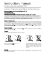
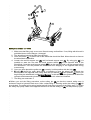
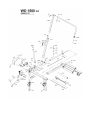
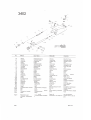
ESCO #90538
For Sales, Service, and
Parts Contact ESCO at
1-800-352-9852
15270 Flight Path Drive, Brooksville FL, 34604 ● 1-800-352-9852 ● www.esco.net ● [email protected]
Instruction manual
Compac wheel dolly, model WD1500.
Important: Read and understand the instruction before use!
Operating and service manual for wheel dolly model WD 1500
Max. Capacity 1500 kg.
Instruction and responsibility:
This instruction and safety manual must be enclosed with the wheel dolly at all times.
It is very important that the owner and the operator completely understand the operating, safety and
maintenance instructions before use. The manufacturer is not liable for wrong- or irresponsible use or
maintenance due to the operators not knowing and following these instructions. If the operator is not
fluent in English, then these instructions and warnings shall be read and explained to the operator in
the operator's native language, making sure that he understands its contents.
How to use the wheel dolly:
WD1500 is a mobile wheel dolly for demounting and mounting large wheels with an outside diameter
of 1150 mm up to 2150 mm (84”). The wheel / load is lifted when the 2 x 4 rollers press horizontally
on each side of the wheel. Lifting will require more force in the beginning as the rollers are pressing
against each other. Lifting occurs with pumping the handle (P). Lowering the wheel/load is activated
by moving the foot pedal (E) into the opposite position. The pump handle (P) can then be used for
lowering the wheel/load again.
Operating instruction:
The unit is operated by moving the foot pedal (E) into lifting or lowering position and afterwards
pumping the pump handle (P).
Labelling:
Warning and CE approval labels are fitted onto the unit.
Make sure that lifting only occurs on a
flat and strong surface / floor.
The wheel/load must be lifted in a vertical
angle as the wheel/load might otherwise
slide on the rollers away from the unit
causing the unit to move towards the
operator.
Mounting:
After opening the packaging check the unit for visible damage, leakage, etc. Please recycle or use
the packing material again.
A
A
W
M
K
H
L
P
F
F
S
E
Safety instructions - LIFTING
1. Make sure that lifting only occurs on a flat and strong surface/floor. If not, lifting with this unit is
prohibited due to risk of danger / damages!
2. The wheel/load should be lifted from the floor.
3. Place the rollers (F) on either side of the wheel that should be lifted. Move the unit as close to
the wheel/load as possible.
4. Loosen the vertical support arm (H) and horizontal support arm (A). By using grip (K) it is
possible to steer the arm with the small support wheel (W) to the opposite side of the
wheel/load. Once the small support wheel (W) is on the opposite side it can be steered behind
the wheel/load. This will prevent the wheel/load from dropping to the opposite side during
manoeuvring.
5. Once you have placed the guide arm (A) correctly, lock its position with the lock (M).
6. !! Lock (L) should be open while lifting or lowering so that the wheel (W) supports the
wheel/load on the opposite side. Kindly note that you should NOT lock position (L). Once you
begin lifting the wheel/load, lock (L) must be open, as this will allow the guide arm to follow the
upwards and downwards movement of the wheel as it is raised and lowered.
7. The lifting can now start. *
* Before you end the lifting procedure, active safety pin (S) so that the manual safety stop is
activated, should a hydraulic leak occur. After a short lifting or lowering action the safety pin (S) will
be activated. The safety pin is spring loaded and will lock the movement of the lifting arms. To unlock
the safety stop pump a little in the opposite direction so that the safety pin (S) can be pulled up again.
Safety instruction - LOWERING / MOUNTING OF WHEEL
1. Release the safety pin (S).
2. Inspect that the small wheel (W) has a firm grip on the wheel/load before lowering.
3. Before lowering the wheel/load make sure that vertical guide lock (L) is released and free to
move.
4. Once you slowly start lowering the wheel/load, the guide arm (L) should be able to freely
follow the movement of the wheel. If not, the risk is that the wheel will drop away from its
support (W) on the opposite side of the wheel and could thereby accidentally fall.
5. Activate the pump lever (P) to lower the load or reach the correct mounting height.
6. Once the unit can be removed from the wheel/load, release locks (K) and swing wheel (W)
away from the wheel. Pull back the unit.
Safety instruction – MANOEUVRING WITH WHEEL/LOAD
1. Ensure that the small support wheel (W) is supporting the wheel/load correctly.
2. Ensure that the locks (M), (L) and (S) are in locked position.
WARNING Safety instructions:
Make sure that lifting only occurs on a flat and strong surface/floor.
The wheel/load must be lifted in a vertical angle as the wheel/load might otherwise slide on the
rollers away from the unit causing the unit to move towards the operator.
Do not overload the unit! Overloading with loads over 1500 kg could result in damage to the unit or
in worst case cause other damage and even accidents!
Lowering a load of more than 1500 kg onto the unit may lead to serious damage to the unit.
Example: If the operator lowers the vehicle itself before lowering and moving the wheel dolly away
from the vehicle.
Before lifting / transporting a load the operator MUST take precautions that the load is not allowed to
drop, and that the weight distribution is safe. The operator must before use take precautions that all
pins are safely locked with split pins or lock rings. (ATTENTION! The LOAD must be blocked with
the guide arm (K) locked and (W) in correct position to support the wheels on the opposite side.)
Always lower the load to the lowest possible position before transportation.
Important! The safety valve is calibrated and sealed by the manufacturer and it is ABSOLUTELY
PROHIBITED to open the seal or adjust its calibration. Offence against the above safety instructions
could in worst case result in loss of the load which could cause personal injury and/or damage to the
unit or properties. In case the unit has any irregularities which could affect the safety, the unit must
not be operated until it has been repaired.
The unit should not be used if there are any oil leakages or if the unit seems different to use than
when it was new. In such cases the unit should be inspected/repaired by a skilled person. More
information on spare parts, etc is available on www.compac.eu under ”Services”.
The manufacture is not liable for wrong use, changes to the construction, use of other spare parts
than original or adjustments/repairs by unauthorised persons.
Safety Maintenance:
Inspection of the unit must only be done without load, for safety reasons. Only authorized/skilled
personnel may repair/adjust the unit. Use only original parts. For adjustment follow the instructions of
the manufacturer. For further information please contact www.compac.eu
Maintenance:
At normal use all mechanical/moving parts only requires a monthly lubrication to be maintained.
The pins must be greased every three months. Important! Use only oil or grease free from acid.
An annual inspection must be performed by a skilled person. Every eventually wearing out or
defective part must be replaced with original spare parts. The owner and- or user must take
precautions that repair is made by a skilled person. Before every use the operator must take
precautions that there are no visible faults such as leaks, damage of the WD and loose or missing
parts. In case the operator suspects that the unit has been overloaded or wrongly loaded it must
before further use be inspected by a skilled person or an authorized.
Oil:
Volume:
Type:
DO NOT use brake fluid, motor oil, etc!
0.6 litres.
Use only hydraulic oil with a gradation (viscosity) of AWS22.
Compac recommends Castrol.
In case the hydraulic unit has a lack of oil or has been taken apart in order to replace the seals then
fill up with the correct oil quantity. Activate the pump handle and add oil slowly through the filling hole
at the plug. The lifting arms must be in minimum position (as close together as possible) when refilling
oil. Warning! Too much oil quantity might cause problems to the hydraulic system.
Decommissioning:
If the unit should ever be scrapped, draw off the oil into an approved container and dispose it at an
approved authority.
10.07.2007 GB/VL
3458A
3461A
WD1500 G3
No.
DANSK.
DEUTSCH.
ENGLISH.
FRANÇAIS.
140
206
828
1144
1208
1314
1324
1421
1540
1711
Skrue
Split
Fitting
Skrue
Trykfjeder
Skive
Spændstift
Skrue
Fitting
Oliebremse
Schraube
Splint
Fitting
Rietstockschraube
Feder
Scheibe
Spannstift
Schraube
Fitting
Senkbremse
Screw
Split pin
Fitting
Pointed screw
Spring
Washer
Elastic pin
Screw
Fitting
Oil valve
Vis
Goupille
Raccord
Vis pointue
Ressort
Rondelle
Goupille de serrage
Vis
Raccord
Frein d`huile
2067BL
2185
2641
2802
2934
3036
3046
3064
3076BL
3192
Hjul
Fitting
Møtrik
Møtrik
Bolt
Fjedersplit
Låsemøtrik
Skrue
Plastprop
Skrue
Rad
Fitting
Mutter
Mutter
Bolzen
Splint
Mutter
Schraube
Kunststoffverschluß
Schraube
Wheel
Fitting
Nut
Nut
Bolt
Split pin
Nut
Screw
Cap
Screw
Roue
Raccord
Ecrou
Ecrou
Boulon
Goupille
Ecrou
Vis
Bouchon
Vis
Låsering
Pumpe, komplet
Kugle/håndtag
Håndtag
Skrue
Skrue
Rulle
Aksel
Bøsning
Stop f. cylinder
Seegerring
Pumpe, komplett
Kugel
Handgriff
Schraube
Schraube
Rolle
Achse
Buchse
Halt
Lock ring
Pump, complete
Ball
Handle
Screw
Screw
Roller
Shaft
Bushing
Stop
Circlips
Pompe, complète
Bille
Manche
Vis
Vis
Poulie
Axe
Manchon
Arrêt
Trykrør
Tårn, teleskop
Støtterør, komplet
Rulleophæng, komplet
Tårn
Cylinder, komplet
Omskiftventil, komplet
Trykrør, komplet
Trykrør
Pumpearm, komplet
Druckrohr
Zwinger, teleskop
Stürtz Rohr, komplett
Chassis, komplett
Zwinger
Zylinder, komplett
Ventil, komplett
Druckrohr, komplett
Druckrohr
Pumpenarm, komplett
Pressure pipe
Tower, telescope
Supporting pipe, compl.
Chassis, complete
Tower
Cylinder, complete
Valve, complete
Pressure pipe, complete
Pressure pipe
Fulcrum arm, complete
Tuyau de refoulment
Chateau, télescope
Support de Tuyau, compl.
Châssis, complète
Chateau
Cylindre, complète
Soupape, complète
Tuyau de refoulment, co.
Tuyau de refoulment
Levier de pompage, com.
Trykrør
Trykrør
Hus f. Lås
Låsetap
Knop f. Lås
Skærm
Hus f. bremse
Skrue
Hjul m. bremse, komplet
Hjul, komplet
Druckrohr
Druckrohr
Gehäuse
Zapfen
Handgriff
Blech
Gehäuse
Schraube
Rad mit bremsen, komplett
Rad, komplett
Pressure pipe
Pressure pipe
Housing
Pin
Handle
Sheet
Housing
Screw
Wheel w. breakes, compl.
Wheel, complete
Tuyau de refoulment
Tuyau de refoulment
Corps
Cliquet de àrrêt
Manche
Plaque
Corps
Vis
Frain pour roue, complète
Roue, complète
Skilt
Nagle
Abseichen
Bolzen
Badge
Shaft
Insigne
Rivet
3384
3402
3440
3441
3443
3444
3446
3453
3454
3456
3457
3458A
3459
3460
3461A
3464
3470
3471
3472
3473
3474
3475
3485
3486
3487
3488
3489
3492
3496
3497
0AL006
0CC028