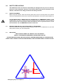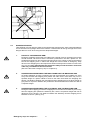
1
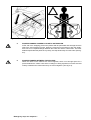
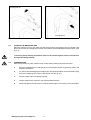
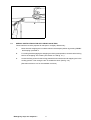
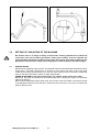
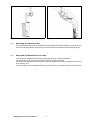
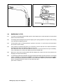
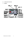
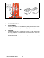
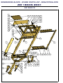
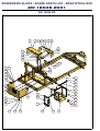
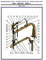
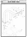
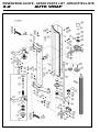
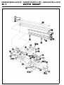
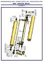
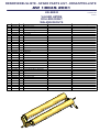
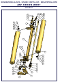
TELLEFSDAL
AUTO WRAP
1804 S
04-2000. Fra serienr.: 190002
USER’S MANUAL
SPARE PARTS LIST
Fiane, N - 4993 SUNDEBRU, NORGE - NORWAY - NORWEGEN
Tlf. (+47) 37 11 92 00 * Fax (+47) 37 15 85 40
11 March 2003
1804e20.wpd
USER'S MANUAL
AUTO WRAP 1804 S
CHAP.
CONTENTS
PAGE
1.0
INTRODUCTION
3
2.0
SAFETY PRECAUTIONS
4
3.0
SETTING UP / MOUNTING OF THE MACHINE
10
4.0
MOUNTING OF PLASTIC FILM
12
5.0
EMERGENCY STOP*
13
6.0
CONTROL BOX
14
7.0
SPEED SETTING OF THE WRAPPING ARM
18
8.0
ADJUSTING THE OVERLAP
19
9.0
OPERATION INSTRUCTION
20
10.0
PERIODIC MAINTENANCE
22
11.0
CHECK POINTS FOR TROUBLE SHOOTING
24
12.0
HYDRAULIC CHART
26
13.0
WARRANTY TERMS
28
* Emergency stop: see chapter 2.1
1
AUTO WRAP 1804 S
Bale wrapping machine
* Emergency stop: see chapter 2.1
2
1.0
INTRODUCTION.
TELLEFSDAL A.S congratulates you with the choice of AUTO WRAP bale wrapping machine. We
are certain you will be satisfied with the machine, and that you will have the pleasure of your
investment for many years.
AUTO WRAP 1804 S is hydraulically driven by its motor. The remote control unit is easy to use and
the functions are clearly marked.
The AUTO WRAP 1804 S is equipped with a patented, special mounting for the rollers, which enables
the machine to wrap square bales.
The AW 1804 S can wrap both square and rectangular bales, from 60 x 60 to 120 x 120 x 190 cm.
It can take bales of up to 1500 kg. It can also wrap round bales of up to ø1500 mm.
The AW 1804 S can be supplied as a TWIN model, i.e. the machine is equipped with two
prestretchers and two cutters. This gives the machines a significantly increased capacity.
The machine is developed and has been improved since the beginning in 1999, and is now a very
reliable and safe machine with high security built in.
This manual is meant to explain how AUTO WRAP 1804 S is prepared, mounted, used and how it
works, and along with the spare part's list be a reference for maintenance and troubleshooting. So
take good care of the book, it is a part of the machine.
Read carefully through this manual, and specially chapter 2.0, safety instructions, before starting
the machine, and follow the instructions thoroughly. If problems should occur, ask your dealer for
advice before you make the problem worse than it is. See also chapter 13.0, conditions of warranty.
AUTO WRAP
Height in working position
Width, min. / max.
Length, min. / max.
Weight
Wrapping arm speed, recom.
Wrapping arm speed, max.
Wheel size / max. air pressure
Bale size, max.
Bale weight, max.
Capacity
Prestretcher
Oil pressure / amount, min.
Electric connection
1804 S
1804 S TWIN
2960 mm
2440 / 3215 mm
2540 / 3425 mm
2460 kg
22 rev. per minute
27 rev. per minute
10,0/80-12BL 4,2bar
120x120x190
1500 kg
Approx. 40 bales per hour
750 mm
150 bar / 25 litres/minute
12 V DC
2960 mm
2440 / 3215 mm
2540 / 3425 mm
2560 kg
22 rev. per minute
27 rev. per minute
10,0/80-12BL 4,2bar
120x120x190
1500 kg
Approx. 40 bales per hour
750 mm
150 bar / 25 litres/minute
12 V DC
TELLEFSDAL A.S reserves the right to alter the product and/or its technical specifications without
prior notice, and without this entitling any alterations to previously supplied products.
© All rights in pursuance of the Copyright Act shall apply, and any reproduction of the contents of this
booklet, in whole or in part, is forbidden without the permission of TELLEFSDAL A.S.
Reservation is made for possible printing errors.
* Emergency stop: see chapter 2.1
3
2.0
SAFETY PRECAUTIONS.
TELLEFSDAL A.S does not take the responsibility for damages that may occur on machine,
persons or other equipment, because of the machine NOT being used as described in this
manual, or because of the safety precautions NOT being followed.
2.1
SAFETY EQUIPMENT.
Before using the machine, make sure that all guards and covers are securely fitted. The machine
must not be operated if a function does not work as described later in this manual. (See chapter 2.4).
The Auto Wrap 1804 S / TWIN models are equipped with an "EMERGENCY STOP" on the
wrapping arm. This device stops all functions instantly, but is by definition not an emergency
stop, because it does not interrupt the feed. Nevertheless it has an equivalent function, so we
have decided to call it an EMERGENCY STOP in this book.
2.2
BECOME FAMILIAR WITH THE OPERATIONS OF THE MACHINE.
If you are unsure how to operate the machine properly, either use of or maintenance to your Auto
Wrap, please contact your Auto Wrap dealer.
2.3
IMPORTANT!
MAKE ALWAYS SURE THAT NOBODY IS IN THE HAZARD
AREA OF THE WRAPPING ARM WHEN THE MACHINE IS IN USE.
THE MACHINE MUST NEVER BE OPERATED BY PERSONS WHOM DOES NOT KNOW ENOUGH
ABOUT HOW TO SAFELY OPERATE THE MACHINE, OR BY PERSONS UNDER 16 YEARS OF AGE.
* Emergency stop: see chapter 2.1
4
Fig. 2-2
2.5
DANGEROUS AREAS.
TELLEFSDAL A.S has given the safety to the operator the highest priority, but it is still impossible to
secure oneself of every danger area on the machine. Therefore we will now go through some of the
dangers that can occur when using the Auto Wrap balewrapper.
1.
PUNCH OF THE WRAPPING ARM.
During the wrapping process the arm rotates with a speed of 20-27 revolutions per minute
around the bale. On the arm there is mounted a prestretcher unit with a plastic roll. The
prestretchers speed can give a person serious injuries if one comes to close to the working
area of the wrapping arm. To reduce this danger we have mounted an emergency stop*
device on the wrapping arm, this stops all movement instantly when someone comes in the
way of it. It is very important that this protection always works and that it should not
under any circumstances be unconnected.
(See more about the emergency stop* in chapter 5.0).
2.
SQUEEZE-DANGER BETWEEN THE MAIN FRAME AND THE WRAPPING ARM.
As earlier explained, we have a wrapping arm with a prestretcher and a plastic roll. Once
every time around this wrapping arm passes the main frame. Here there may occur a
squeeze danger if a person stands to close to the main frame when the wrapping arm
passes. The distance between the main frame and the wrapping arm is not large enough to
give place for a person. Between the prestretcher and the bottom frame there can also be
a squeeze danger.
3.
SQUEEZE-DANGER BETWEEN THE STATIONARY AND THE WRAPPING ARM.
During the main wrapping process the wrapping arm moves around a stationary arm. Every
time the wrapping arm passes the stationary arm, there is a squeeze danger that can be
dangerous for the fingers. The distance between the stationary and the wrapping arm is
between 25-40 mm. (See fig. 2-2).
* Emergency stop: see chapter 2.1
5
Fig. 2-3
4.
SQUEEZE DANGER BETWEEN THE ROLLERS AND THE MAIN FRAME.
When adjusting the width of the rollers there is a danger of being squeezed. Keep away from
this area, fingers and feet also. (See fig. 2-3).
* Emergency stop: see chapter 2.1
6
Fig. 2-5
Fig. 2-6
5.
SQUEEZE DANGER CAUSED BY PLASTIC AUTOMATION.
At the end of the wrapping process the plastic shall be perforated and held tight until the
start of the next wrapping process. When the cutter arm moves down to lock the plastic,
there can occur a squeeze danger between the cutter arm and the cutter holder. The cutter
blade that perforates the plastic is very sharp, so keep hands away from the cutter. (See fig.
2-5).
6.
SQUEEZE DANGER BETWEEN THE ROLLERS.
When the rollers on the machine are moved together, there is not enough space for a
person between the rollers. Here there is a danger of being squeezed, so make sure that
nobody is between the rollers when they are moved together. (See fig. 2-6).
* Emergency stop: see chapter 2.1
7
Locking bolt off
Locking bolt on
Fig.2-7a
2.5
Fig. 2-7b
LOCKING THE WRAPPING ARM.
When the machine is not in use, make sure the locking bolt for the wrapping arm is mounted. If the
bolt is not mounted, the wrapping arm and/or the machine could be damaged during transport. (See
fig. 2-7).
Connecting heavy working implements often has an overall negative effect on the tractor's
driving and braking capacity.
2.6
TRANSPORTING.
When transported on a public road there are certain safety measures that must be taken:
1.
Move the wrapping arm in under the davit in the transport position by pressing "STOP" and
keeping it pressed in.
2.
For locking and disengaging the wrapping arm during transportation, ensure that the locking
bolt for the wrapping arm is fitted. (See section 2.5 and fig. 2-7.)
3.
Move the main rollers completely together.
4.
Always transport the machine in the lowest possible position.
5.
Make sure that the machine dos not cover the tractors lights. If necessary, mount extra lights.
* Emergency stop: see chapter 2.1
8
Fig. 2-8
2.7
SPECIAL INSTRUCTIONS FOR AUTO WRAP 1804 S TWIN
These machines must be prepared for transport in a slightly different way:
1.
Move the main wrapping arm in under the davit in the transport position by pressing "STOP"
and keeping it pressed in.
2.
For locking and disengaging the wrapping arm during transportation, ensure that the locking
bolt for the wrapping arm is fitted. (See section 2.5 and fig. 2-7.)
3.
Loosen the fixing screws for the locking plate which secures the second wrapping arm in the
working position. Then swing the arm in towards the davit. (See fig. 2.8.)
(See also sections 3 to 5 for the standard machines)
* Emergency stop: see chapter 2.1
9
Fig. 3-1
3.0
Fig. 3-2
SETTING UP / MOUNTING OF THE MACHINE.
Be careful! There is a danger of being crushed when working implements are fitted and
connected. Carry out the fitting procedures slowly and carefully, and use separate and
approved lifting equipment to make the work easier. See section 2 on safety regulations and
pay attention to the various safety decals displayed on different parts of the bale wrapper.
3.1
HINGED TOWER.
Because of the freighting of the machine, AUTO WRAP 1804 S is sometimes delivered with the tower
hinged down. The bracing clamps have to be fitted on each side of the davit. Fit the lower fixing
screws for the clamps (8 screws size 12 x 140). Inn some cases it may be necessary to adjust the
tower so that the tower and the rollers are right angel parallel.
SCREW IN SECURELY and after several hours' use, tighten all the screws once again.
Before use, the tower must be lifted up and fastened with 5 pcs. 16mm bolts. (Figure 4-1 shows the
machine at delivery).
Remove all packing strips and lift up the tower. Use a crane or the front-loader on the tractor and lift
in the liftingpoint at the top of the machine. (See arrow).Then mount the 5 pcs. M16 x 55 bolts with
washers and lock nuts.
* Emergency stop: see chapter 2.1
10
Fig. 3-4
Fig. 3-5
3.2
MOUNTING OF PRESTRETCHER.
It is to be fastened with the same 2 bolts that the locking bracket is fastened with. (You don't have to
remove the locking bracket). Remove the nuts and mount the prestretcher and the wrapping arm.
3.3
MOUNTING OF EMERGENCY STOP* ARM.
The machine is equipped with emergency stop-arms on each of the prestretchers.
The releasing arm for the emergency stop component must be mounted.
Put the arm into the bracket and mount the hinge bolt. Replace the washers and tighten the locking
nuts. (See fig. 3-5).
The return spring is to be fastened between the eye bolt on the arm and the eye bolt on the bracket.
* Emergency stop: see chapter 2.1
11
Fig. 4-1
Fig. 4-2
4.0
MOUNTING OF PLASTIC FILM.
4.1
When the plastic roll shall be mounted, you have to hold the prestretcher-rollers aside, Hold the rollers
aside and put on the holding hook. (See fig. 4-1).
4.2
Place a reel of film on to the prestretcher's holding axle and put on the springloaded lock. On delivery
the prestretcher is set for the 750mm film, the top bracket may be moved down enabling the use of
the 500mm film. (See fig. 4-3).
4.3
Pull the film between the rollers on the prestretcher in the direction of the arrow. (See fig. 4-2).
(See also the sign on the wrapping arm).
4.4
The filmholder / cutter is opened, pull out the film and place it over the U-shaped slot.
4.5
The cutter is closed, and the film will be held in place.
Fig. 4-3
* Emergency stop: see chapter 2.1
12
Fig. 5-1
Fig. 5-2
5.0
EMERGENCY STOP.
5.1
The machine is equipped with a safety guard on the wrapping arm, and its operation must be tested
before work itself is started.
5.2
The safety guard is designed to stop the wrapping arm injuring operators or objects, when starting
up or during the wrapping process.
5.3
The emergency stop* is constructed with a "positive" connection, i.e. it has to be in full order before
the machine can be started.
5.4
This consists of a release guard which is connected by a wire to the lever arm, and this activates a
small electrical switch via a sliding contact (14, fig. 5-2).
If the electrical circuit is broken, the hydraulic oil flow is cut off and all functions stop immediately.
This is indicated on the control box display by three illuminated dots.
5.5
Before use, this function must be tested. Start the wrapping arm, hold out an arm or any obstacle, the
wrapping arm stops before hitting.
5.6
To restart the machine the obstacle must be removed and the safety guard must return to its original
position. If "STOP" is pressed before "START", the wrapping continues from the point in the program
at which the emergency stop was activated. If, on the other hand, "STOP" is pressed before "ZERO",
then the wrapping sequence starts from the beginning again.
(See more in section 7.)
* Emergency stop: see chapter 2.1
13
6.0
CONTROL BOX FUNCTIONS.
6.1-1
FUNCTIONS
Arm model.
* Emergency stop: see chapter 2.1
14
7.1-2
PROGRAMMING
Arm model.
Auto-wrap Controlbox
2000
16 mars 2000 JH
2. Programing
Notice:
By pressing "EXIT" more than 3 sek.you allways will be braught back to "Wrap-cycle" ( Wrapp modus)
By pressing "MENU" more than 3 sek, the display contrast will be adjusted. "MENY" up = Stronger MENY down = weaker
Manual operation
Behind the rubberplug on the the rear side of the control box it is placed a switch for manual/automatic operation.
Please notice that the display does`nt work in manuel modus.
Display nbr ( )
Wrap cycle: 0-10
Balecounter 1:
Programing nbr laps/bale
MENU
Adjust flashing numbers
SET:
Change
SET:
next
EXIT:
Store
EXIT:
Store
EXIT:
Store
2
MENU
Reset
Modell
Setup
3
SET:
Change
1514 TWIN
1510 TWIN
1514
1510
1300
MENU
Find the right
model
5
6
7
8
9
10
11
12
13
14
15
16
17
Actual RPM:
(Alarm limits :23-27)
Press SET to change settings
Stop bale rotation first filmlayers
Stop bale rotation numbers of layers
Rotate slow start duration
Film layers until release film
Rev.puls to cutter open delay
Release film (open) duration
Rotate fast ,start of final rev.
Pass sensor duration, (before film cut)
Cut film (close) duration
Reverse duration, after film cut. (Twin)
Manuall rollers - in hold duration
Manuall rollers - out hold duration
Manual rotate bale hold duration
EXIT:
Store
EXIT
Store
MENU
1300
*
*
3.0
2.0
0.5
0.4
1.0
1.0
2.0
*
0.0
0.0
0.0
1510 1514 1510T 1514T
*
*
3.0
2.0
0.5
0.4
1.0
1.0
2.0
*
0.0
0.0
0.0
No
4.0
3.0
2.0
0.5
0.4
1.0
1.0
2.0
*
0.0
0.0
0.0
No
4.0
3.0
2.0
0.0
0.3
0.4
0.9
2.0
1.5
0.0
0.0
0.0
No
4.0
3.0
2.0
0.0
0.3
0.4
0.9
2.0
1.5
0.0
0.0
0.0
MENU :
Adjust flashing
numbers
EXIT:
Store
Actual wrapping speed
Alarm on 23 rpm Stop 27 rpm
Home (2 )
20
Balecounter
21
SET:
Change
* Emergency stop: see chapter 2.1
15
22
22
23
24
25
Reset possible ?
Yes
Bales total for all 9 balecounters
Bales machine total
No
Balecounter 1: 2: 3:
Yes
Balecounter 4: 5: 6:
Yes
Balecounter 7: 8: 9:
Yes
Working HRS:
Machine tot:
SET:
Change
MENU:
Reset
EXIT:
Store
SET:
Change
MENU
Reset
EXIT:
Store
SET:
Change
26
Reset possible ?
Yes
26 Working hours since last reset
26 Working hours machine total
Audioalarm &
Display
27
28
SET:
Change
Dänish
English
Nederlands
Francais
Deutsch
EXIT:
Store
MENU:
Adjust flashing
numbers
EXIT:
Store
SET:
Change
29 Audio alarm
30 Display contrast
31 Display light
HardwareTest
MENU:
Adjust flashing
numbers
Home (2 )
Language :
No
On
100
On
SET:
Enter
32
Description
33 Supply voltage
Present voltage
Last drop to
Last registrated drop of voltage.
34 Test keys pressed
000.000
35 Test switches aktivated 00.00.00.00.00
36 Relays, 0=off.AMP nbr 0--.0000.000-.-00
( Test relayoutputs. AMP sprocket 1-14 )
37 Counter input
Notice ! nbr 10,11,12.13,14 are indicated with A,B,C,D,E
Inputsignal from counterswitch
1=Yes O= No
Emergencystop input
Nr 2:
Nr 3:
38 Infra Red reciever input
39 Test Infra Red remotecontrol 00.00.00.00
* Emergency stop: see chapter 2.1
EXIT:
Store
(Test 6 programbuttons)
(Test av 5 stk funktion switches)
Inputsignal from Em.stop switch
1=Yes O= No
Is the IR reciever connected.
1=Yes O= No
Inputsignal from IR sender
1=Yes O= No
16
SET:
A signal change
the displayed
out/in put from
0 into 1.
6.1-3
WRAPPING CYCLE
Arm model.
12,00
12,00
Programpages
H
21,00
J
LT 2000
Start
A
B
C
15,00 D
D
CR- 900 3-7
B
0:15
(7)
0:26
0:14
( 8)
(9)(10)
0:16
( 11 )
Start 1/2 speed
1/1 speedsignsl to valve nbr6
1 lap displayed
2 laps displayed
Release film from cutter.
I
G
E
F
revolution per/bale (-2)
E
Display adds 1 per laps.
D
C
A
Wrapping
Runs further into nbr of progr.
F
Stop
Stopsequence starts.
G
Time duration until cutter is
Start/stop
opening.
H
18,00
Cunterswitch
The cutter is opening completly
wrapp.arm slows down. (1/2 )
I
J
Duration from "I" to stop.
Wrapp.arm stops and cutter
close and hold the film.
Traktor
* Emergency stop: see chapter 2.1
17
0:17
0:18
0.19
( 12 )
( 13 )
3.Wrapping cycle
Rotation
Fig. 7-1
7.0
SPEED-SETTING OF THE WRAPPING ARM.
7.1
Start the motor, let it run at approx. 2400 revolutions per min. The oil flow to the packing machine is
adjusted with the use of two control valves which are situated behind the machines "neck".[see fig.
7-1]
7.2
The control valve on the right-hand side, is for adjustment of the wrapping arm speed.
7.3
Adjust the wrapping arm speed to approx. 22 revolutions per minute. (Just below three seconds per
revolution.) The adjustment is carried out by turning the wheel on the control valve. Turning
clockwise REDUCES the speed and turning counterclockwise INCREASES the speed.
It is recommended not to wrap with higher speed than 22 revolutions per minute, because then the
plastic film will "catch" more air, this air can then not escape from the bale. The result is poor quality
fodder.
OBS!
Max. allowed wrapping arm speed is 27 revolutions per minute.
REMEMBER!
Increased speed of tractor engine do not increase the wrapping speed, it only increases the
oil flow into the system and by that also the temperature in the hydraulic system.
* Emergency stop: see chapter 2.1
18
Fig. 8-1
Fig. 8-2
8.0
ADJUSTING THE OVERLAP.
8.1
WRAPPING ARM SPEED.
Load a bale on to the machine. To be able to adjust correct overlap, check that the wrapping arm has
a speed of approx. 22 revolutions per minute. If not, adjust this by turning the control valve for
wrapping arm speed. (See chapter 7.3). When the wrapping arm speed is OK, you can set the
overlap.
8.2
OVERLAPPING.
Use a black marker to mark a line on the middle of the film wrapped on the bale. Adjust the control
valve for roller speed, (see fig. 8-1), so that the marker line is just covered. Approx. 52-53% is the
ideal overlap. (See fig. 8-2).
This adjustment can be kept as long as you wrap bales with approx. same diameter. When changing
bale size, control the overlap.
* Emergency stop: see chapter 2.1
19
Fig. 9-1
9.0
OPERATION INSTRUCTION.
We shall now go through a complete wrapping process, from loading to storage place, and explain
the practical use of Auto Wrap 1804 S.
9.1
WRAPPING SQUARE BALES.
a)
Minimum recommended bale size is 60 x 60 cm. If you wish, you can place two bales on top
of each other, and wrap them together as a bale of 120 x 90 cm. (Max. bale size is 120 x 120
cm).
b)
When wrapping rectangular bales, (e.g. 70 x 120 cm), the bale will rotate with uneven speed.
To get a smoother wrapping, or if you want more film on the long sides of the bale, it is
possible to mount an extra hydraulic valve that stops the rotation of the bale while the
wrapping arm continues to go.
c)
Sometimes it can be necessary to move the width between the rollers while wrapping. This
is most common when wrapping bad shaped and loosely pressed bales. If the machine has
problems rotating the bale, you can move the rollers in or out with the ROLLER OUT or
ROLLER INN with the control box while wrapping. Suggested roller width adjustment, (se
fig. 9-1).
9.2
START.
Remember that the plastic film end has to be locked in the U-shaped slot before starting the wrapping.
When the plastic film end is in the slot, push “AUTO”, and the wrapping arm now moves at ½ speed
for approx. one half revolution before it automatically switches to full speed. This is to avoid damage
of the film when starting. When the wrapping arm has done a couple of revolutions, the cutter-arm
automatically releases the film end. (See also chapter 6).
9.3
OVERLAP.
Control that the overlap is correct. If not, see chapter 8.0.
9.4
HOW MANY LAYERS OF PLASTIC FILM?
When the bale is completely covered with film, read the counter that displays the number of
revolutions done by the wrapping arm. This number has to be multiplied by 2 or 3, depending on how
many layers of film you want to have.
* 4 layers - multiply by 2.
* 6 layers - multiply by 3.
As long as you wrap bales with the same diameter, you can stop at the same number every time.
* Emergency stop: see chapter 2.1
20
9.5
STOP.
When the required number of revolutions is obtained, push the “AUTO”-button. The wrapping arm
will now rotate 1-2 revolutions, the cutter moves up, the arm speed is reduced and it stops at the right
place for next wrapping cycles. Then the cutter closes automatically, and the film is held tight in the
U-formed slot and perforated. The bale is now completely wrapped and will automatically off loaded
with the function rotation of bales. (Se more in chap.6.0)
* Emergency stop: see chapter 2.1
21
10.0
PERIODIC MAINTENANCE.
10.1
BEARINGS.
All ball-bearings are packed with grease, and do not need any more maintenance.
10.2
PRESTRETCHER.
If the machine is in daily use, the guiding sleeves at the prestretcher should be oiled once a week or
when needed. Sprockets and bearings on the prestretcher should also be oiled when needed.
10.3
CUTTER / FILM HOLDER.
The cutter / film holder is preadjusted from the factory and does not need further adjustments. When
replacing spares it may be necessary to re-adjust. The springs for the U-shaped slot must be adjusted
so that they are almost completely squeezed together when the cutter-arm is all the way down. If the
cutter arm must be adjusted take care so that the arm meets in the middle of the u-shaped slot and
that the cutter arm does not squeeze the springs completely together.
10.4
LINK BEARINGS.
The link bearings between the main frame and roller arms must be greased once a week or, as,
required.
10.5
GEAR OIL. (Applies only to TWIN machines.)
The oil in the gears of the wrapping motor must be changed after the first 100 hours of operation, and
then every 2,000 hours or at least once a year. Fill up with new oil, the quantity being about 0.25
litres. Use EP gear oil in the viscosity group VG 150 (ISO 3448) or similar. See the table of approved
oils.
TYPE OF OIL
+5° C / +40° C IV 95 min. (VG 150, ISO 3448)
AGIP
Blasia 150
ARAL
Degol BG 150
BP MACH
GR XP 150
CASTROL
Alpha SP 150
CHEVRON
Non leaded gear compound 150
ELF
Reductelf SP 150
ESSO
Spartan EP 150
I.P.
Mellana 150
MOBIL
Mobilgear 629
SHELL
Omala oil 150
TOTAL
Carter EP 150
10.6
OIL FILTER.
The oil filter must be changed once a year.
10.7
HYDRAULIC CYLINDERS.
Make sure that all hydraulic cylinders are closed when storing the machine.
* Emergency stop: see chapter 2.1
22
10.8
CHAINS/CHAIN TIGHTENERS
After some hours' use the chains at the outer end of the rollers, on the square-bale units must be
tightened. Take off the covers at the end of the rollers, loosen the bolts on the chain tighteners just
a little, and turn the chain tighteners until the chains are tight enough. (No tighter than that the rollers
are able too rotate easily when the motor is in neutral). Re-bolt the chain tighteners. The chains must
be greased regularly. Use grease or chain saw oil. The chains should be dismounted, cleaned and
greased ones a year. Place the chains in oil for 2-3 days, then hang them up to run off.
10.9
SQUARE-BALE UNIT
After a period of wrapping, grass will collect around the flanged bearings on the square-bale unit.
When this becomes wet, acids can form in the grass which can damage the bearings. This grass
must therefore be removed at regular intervals.
10.10
SCREWED FITTINGS
Make a general check of all screwed fittings and tighten where necessary.
Pay attention if removing the wrapping arm as this is fitted on a conical shaft journal and can
therefore fall off as soon as the fixing screw is removed from the end of the shaft journal.
Always secure the wrapping arm with a strap or something similar to prevent it falling off,
BEFORE THE FIXING SCREW IS LOOSENED.
10.11
CLEANING.
The machine should be cleaned and oiled regularly and by the end of the wrapping season.
NOTE !
When using high pressure washing apparatus, care must be taken with the electrical
installation.
Also make sure that water is not sprayed directly into the bearings, etc..
Keep the control box protected from rain and water. If necessary use compressed air to dry
electrical components.
10.12
STORAGE.
The machine should be parked in a dry place during the closed season.
* Emergency stop: see chapter 2.1
23
11.0
CHECK POINTS FOR TROUBLE SHOOTING.
11.1
GENERAL CHECK POINTS.
In this chapter we have some general check points that have to be examined first if something is
wrong with the machine.
There are three basic assumptions that have to be fulfilled if the machine shall function properly:
1.
2.
3.
The oil pressure from tractor should be 150 bar.
The return flow of oil has to be as free as possible, max. 10 bar counter pressure.
Enough electric power to all functions.
11.2
OIL AMOUNT.
The oil amount must be approximately 25 litres / minute,
REMEMBER! Large oil amount = Valves get hot.
11.3
ELECTRIC POWER.
It is important to check that all function gets enough electric power.
If not, some, or all functions may fall out.
Is the battery voltage high enough?
The control box display indicates the voltage being supplied if this is too low.
If the voltage falls below 10 volts this is treated as an interruption of the power supply and all
functions stop.
Are the cables correctly connected to the battery?
Is the connection between battery cable and control unit OK?
Clean off the poles and check that the plug comes correct in place.
Is the connection between remote control unit and machine OK?
Change contacts if any doubt about the condition.
Is the fuse on the battery cable OK?
In addition to the fuse on the battery cable, there is a fuse inside the remote control. This is 10A, and
secures the current to the magnet valves.
PLEASE CONTACT YOUR DEALER IF YOU ARE IN DOUBT OF ANYTHING.
(Remember always to give your dealer the serial number and productionyear of your machine
when contacting dealer and when ordering spare parts).
* Emergency stop: see chapter 2.1
24
There are 3 basics which must ALWAYS be followed if the machine is to function correctly
* Emergency stop: see chapter 2.1
25
12.0
ELECTRIC, HYDRAULIC CIRCUIT DIAGRAM.
12.1
ELECTRIC CHART.
* Emergency stop: see chapter 2.1
26
12.2
HYDRAULIC CHART.
* Emergency stop: see chapter 2.1
27
RESERVEDELSLISTE - SPARE PARTS LIST - ERSATZTEILLISTE
AW 1804S 2001
AW 1804S FR
41
12
40
11
14
37
38
18
38
39
44
38
38
36
41
43
40
42
41
15
36
38
13
16
46
2
1
19
9
20
32
35
28
29
27
33
46
16
21
31
35
33
26
8
17
27
45
28
24
4
22
23
3
5
29
6
30
7
29
25
10
32
33
33
34
RESERVEDELSLISTE - SPARE PARTS LIST - ERSATZTEILLISTE
AW 1804S 2001
AW 1804S FR
HOVEDRAMME (1/2)
MAIN FRAME (1/2)
HAUPTRAHMEN (1/2)
Item Part number
Beskrivelse
Qty
Description
1
34240084
1
Ramme
2
34240019
1
Tipprull
3
34611490
1
Drag spesial
4
34611489
1
Drag standard
5
34240024
1
Drag
6
34240023
1
Støttebein fot
7
34240022
1
Støttebein
8
34240046
1
Sylinder FA5030200H20H20
9
34240058
1
Rørkappe
10
34240017
2
Knivholder
11
34240060
1
Deksel over ventiler
12
34240057
1
Deksel bak motor
13
34240056
2
Holder for batteri
14
34240063
1
Holder kort
15
34240064
1
Holder lang
16
34240020
2
Feste for tipprull
17
34101100
1
Bolt 25 x 195 (220)
18
34240065
1
Holder for fjernkontroll
19
34240069
1
Støtte for skjerm over ventil
20
34240050
4
Bolt for anslagstopp
21
34321519
2
Lager m/hus FYH SAPFL-206
22
34302125
8
Skive 17 DIN 125 Ez
23
34111500
4
Skr. 6k. DIN 933 M16 x 50-8.8 Ez
24
34232100
4
Mutter lås DIN 985 M16-8 Ez
25
34111992
1
Skr. 6k. DIN 931 M20 x 180-8.8 Ez
26
34110070
1
Skr. 6k. DIN 931 M30 x 200-8.8 Ez
27
34110062
2
Skr. 6k. DIN 931 M20 x 80-8.8 Ez
28
34233000
3
Mutter lås DIN 985 M20-8 Ez
29
34302126
6
Skive 21 DIN 125 Ez
30
34234600
1
Mutter lås DIN 985 M30-8 Ez
31
34110300
4
Skr. 6k. DIN 933 M10 x 30-8.8 Ez
32
34230900
16
Mutter lås DIN 985 M10-8 Ez
33
34302122
32
Skive 10,5 DIN 125 Ez
34
34117245
4
Skr. 6k. DIN 933 M10 x 45-8.8 Ez
35
34117200
8
Skr. 6k. DIN 933 M10 x 35-8.8 Ez
36
34110001
3
Skr. 6k. DIN 933 M8 x 35-8.8 Ez
37
34230500
5
Mutter lås DIN 985 M8-8 Ez
Nut lock DIN 985 M8-8 Ez
38
34302121
12
Skive 8,4 DIN 125 Ez
Washer 8,4 DIN 125 Ez
39
34230400
1
Mutter 6k. DIN 934 M8-8 Ez
40
34117100
7
Skr. 6k. DIN 933 M6 x 16-8.8 Ez
41
34302120
11
Skive 6,4 DIN 125 Ez
42
34230300
2
Mutter lås DIN 985 M6-8 Ez
43
34110083
2
Skr. 6k. DIN 931 M6 x 20-8.8 Ez
44
34110000
2
Skr. 6k. DIN 933 M8 x 25-8.8 Ez
45
34200100
5
Orpinne 8mm
46
34060800
3
Smørenippel A M8 x 1 DIN 71412
Washer 17 DIN 125 Ez
Nut lock DIN 985 M16-8 Ez
Nut lock DIN 985 M10-8 Ez
AW1804S fr.idw
07.06.01
Bezeichnung
RESERVEDELSLISTE - SPARE PARTS LIST - ERSATZTEILLISTE
AW 1804S 2001
AW 1804S BA
2
8
6
31
30
11
29
16
19
17
18
16
10
24
23
24
27
5
26
23
31
28
3
1
16
22
23
17
12
9
23
29
24
15
28
28
21
14
20
24
33
23
15
7
23
27
32
25
14
4
20
RESERVEDELSLISTE - SPARE PARTS LIST - ERSATZTEILLISTE
AW 1804S 2001
AW 1804S BA
HOVEDRAMME (2/2)
MAIN FRAME (2/2)
HAUPTRAHMEN (2/2)
Item Part number
Qty
Beskrivelse
Description
1
34240084
1
Ramme
2
34240055
1
Toppdeksel
3
34240066
2
Glidebeslag for skjermholder
4
34240062
1
Motorramme for Kubota
5
34240061
1
Deksel rundt motor
6
34240054
1
Feste for toppdeksel
7
34240068
2
Støtte for skjerm
8
34240071
1
Hake eksenterstrammer galv. 31C
9
34240070
1
Lås eksenterstrammer galv. 702LC
10
34240067
2
Stag for deksel
11
34240072
3
Hengsle KAR 2230770 37x37x75
12
34240087
1
Overvange løs motor ramme
13
34302126
1
Skive 21 DIN 125 Ez
14
34240096
2
Radiator opheng
15
34240097
2
Avskjerming over/under
16
34302121
8
Skive 8,4 DIN 125 Ez
Washer 8,4 DIN 125 Ez
17
34230500
6
Mutter lås DIN 985 M8-8 Ez
Nut lock DIN 985 M8-8 Ez
18
34230400
2
Mutter 6k. DIN 934 M8-8 Ez
19
34112700
2
Skr. 6k. DIN 933 M8 x 30-8.8 Ez
20
34302138
14
Skive 11/34 x 3 DIN 440
21
34110014
6
Skr. 6k. DIN 933 M10 x 20-8.8 Ez
22
34119207
2
Skr. 6k. DIN 933 M6 x 70-8.8 Ez
23
34302120
25
Skive 6,4 DIN 125 Ez
24
34230300
8
Mutter lås DIN 985 M6-8 Ez
25
34240099
1
Holder for avskjerming
26
34240093
1
Holder for koblingsboks
27
34110083
4
Skr. 6k. DIN 931 M6 x 20-8.8 Ez
28
34117100
11
Skr. 6k. DIN 933 M6 x 16-8.8 Ez
29
34112600
23
Skrue M5 x 12 senkehode
30
34302119
24
Skive 5,3 DIN 125 ElZn
31
34230100
24
Mutter lås DIN 985 M5-8 Ez
32
34420007
4
Vibr.demp. ø70x45 M10 20290 65Sh
33
34230900
8
Mutter lås DIN 985 M10-8 Ez
Nut lock DIN 985 M10-8 Ez
AW1804S BA.idw
30.08.01
Bezeichnung
Scheibe 8,4 DIN 125 Ez
RESERVEDELSLISTE - SPARE PARTS LIST - ERSATZTEILLISTE
AW 1804S 2001
TÅRN 1804
6
14
13
31
15
7
22
21
5
19
20
9
3
38
18
20
30
12
20
30
25
26
39
28
2
29
35
26
36
8
36
16
23
28
27
25
10
11
9
17
34
33
33
32
1
24
27
4
RESERVEDELSLISTE - SPARE PARTS LIST - ERSATZTEILLISTE
AW 1804S 2001
TÅRN 1804
TÅRN KOMPLETT
TOWER COMPLETE
TURM KOMPLETT
Item Part number
Qty
Beskrivelse
TÅRN 1804.idw
16.05.01
Description
Bezeichnung
1
34240074
1
Sveiv
Wrapping arm
Wickelarm
2
34240075
1
Tårn
Tower
Turm
3
34670205
1
Gearholder
4
34670167
1
Forstrekkerarm
5
34251313
1
Sveivlås
6
34090181
1
Gear vinkel RT90 - 3,1:1 ø35
7
34090200
1
Hydraulikkmotor AR 200 NC25 FPDA
8
34130261
1
Sveivaksel
9
34312009
2
Spennbrikke DIN 6796 M20
10
34302139
1
Skive sveivboss 22/55 x 6
11
34111196
1
Skr. 6k. DIN 933 M20 x 50-8.8 Ez
12
34302159
4
Skive sfærisk 10,5 DIN 74361
13
34570009
1
Skive 17/50 x 8
14
34115600
1
Skr. 6k. DIN 933 M16 x 35-8.8 Ez
15
34670206
1
Lås for gearholder
16
34380511
1
Glideplate for nødstopp
17
34611455
1
Giver for rundeteller (97-)
18
34310500
8
Skive spreng DIN 7980 10 mm Ez
19
34110014
2
Skr. 6k. DIN 933 M10 x 20-8.8 Ez
20
34302122
6
Skive 10,5 DIN 125 Ez
Washer 10,5 DIN 125 Ez
Scheibe 10,5 DIN 125 Ez
21
34110029
2
Skr. syl. DIN 912 M12 x 30-12.9 S
22
34310600
2
Skive spreng DIN 7980 12 mm Ez
23
34117500
2
Skr. 6k. DIN 931 M12 x 70-8.8 Ez
24
34231300
2
Mutter lås DIN 985 M12-8 Ez
Nut lock DIN 985 M12-8 Ez
Schließmutter DIN 985 M12-8 Ez
25
34240702
2
Låsering I-80
26
34240703
2
Låsering A-50
27
34302135
4
Skive 13/40 x 2
28
34320503
2
Lager sporkule 6010 2RS
29
34270000
1
Kile pass B10 x 8 x 70
30
34110015
12
Skr. 6k. DIN 933 M10 x 25-8.8 Ez
31
34047011
1
Pakning motor/vinkelgear
32
34302121
2
Skive 8,4 DIN 125 Ez
Washer 8,4 DIN 125 Ez
Scheibe 8,4 DIN 125 Ez
33
34119012
3
Skr. 6k. DIN 933 M8 x 10-8.8 Ez
34
34310400
1
Skive spreng DIN 7980 8 mm Ez
35
34118400
5
Skr. 6k. DIN 931 M16 x 55-8.8 Ez
36
34302125
10
Skive 17 DIN 125 Ez
Washer 17 DIN 125 Ez
Scheibe 17 DIN 125 Ez
38
34117200
2
Skr. 6k. DIN 933 M10 x 35-8.8 Ez
39
34230900
2
Mutter lås DIN 985 M10-8 Ez
Nut lock DIN 985 M10-8 Ez
Schließmutter DIN 985 M10-8 Ez
40
34232100
5
Mutter lås DIN 985 M16-8 Ez
Nut lock DIN 985 M16-8 Ez
RESERVEDELSLISTE - SPARE PARTS LIST - ERSATZTEILLISTE
2-4
AUTO WRAP TWIN
RESERVEDELSLISTE - SPARE PARTS LIST- ERSATZTEILLISTE
AUTO WRAP TWIN
2-4
1804-2-4.wpd
11. mars 2003
FORSTERKNINGER, TÅRN
ENFORCEMENT, TOWER
VERSTÄRKUNG, TURM
Pos
Art. Nr.
No
Beskrivelse
Description
Bezeichnung
Type - Dimension
1
2
3
4
5
34611427
34611428
34260125
34111300
34302123
1
1
2
12
24
Forsterkning, høyre
Forsterkning, venstre
Klemplate
Skrue
Skive, underlag
Enforcement, right
Enforcement, left
Clamp plate
Bolt
Washer
Verstärkung, Rechts
Verstärkung, Links
Klemmplatte
Schraube
Scheibe
M12 x 140, DIN 931
12 mm
6
34231300
12
Mutter, lås
Nut, lock
Schließmutter
M12, DIN 985
RESERVEDELSLISTE - SPARE PARTS LIST - ERSATZTEILLISTE
7-2
AUTO WRAP 1804 S
RESERVEDELSLISTE - SPARE PARTS LIST- ERSATZTEILLISTE
AUTO WRAP 1804 S
7-2
1804-7-2.wpd
11. mars 2003
OMDREININGSTELLER
REVOLUTIONS COUNTER
UMLAUFSZÄHLER
Pos
Art. Nr.
No
Beskrivelse
Description
Bezeichnung
Type - Dimension
1
2
3
4
5
34670133
34950333
34950418
34950419
34119007
1
1
1
1
2
Bryterbrakett
Endebryter
Nippel
PG-Reduc.
Skrue
Switch bracket
Limit switch
Nipple
PG-Reduc.
Bolt
Halter für Endschalter
Endschalter
Nippel
Reduzierstück
Schraube
Honeywell,GLEB01A5A
Skintop st9 PG-9
Skindicht-kkk 15.5/9
M5 x 35, DIN 931
6
7
8
9
10
34302136
34230100
34117100
34302134
34611420
2
2
2
2
2
Skive
Mutter, lås
Skrue
Skive
Giver
Washer
Nut, lock
Bolt
Washer
Giver
Scheibe
Schließmutter
Schraube
Scheibe
Geber
5,3/15 x 1,25
M5, DIN 985
M6 x 16, DIN 933
6,4 x 20 x 2
11
12
34119012
34302145
2
2
Skrue
Skive spreng
Bolt
Spring washer
Schraube
Sprengen scheibe
M8 x 10, DIN 933
8mm
RESERVEDELSLISTE - SPARE PARTS LIST - ERSATZTEILLISTE
3-2
AUTO WRAP
RESERVEDELSLISTE - SPARE PARTS LIST - ERSATZTEILLISTE
AUTO WRAP
3-2
auto-3-2.wpd
11. mars 2003
FORSTREKKER 750mm
PRESTRETCHER 750mm
VORSPANNER 750mm
Pos
Art. Nr.
No
Beskrivelse
Description
Bezeichnung
Type - Dimension
*
34920611
-
Forstrekker, komp. uten
skjerm og krok.
Plastrull
Prestretcher,comp.without cover and hook.
Film roll
Vorspanner, komplett ohne
Deckel und Einhänghaken.
Folienrolle
750 mm
*
34480028
-
1
2
3
4
5
34670150
34660104
34920618
34240728
34320516
1
1
1
1
2
Åpen holder
Holdekrok
Låseholder,komplet
Låsering
Lager, sporkule
Open holder
Hook
Lock container
Locking ring
Track ball bearing
Halterung
Einhänghaken
Festestellvorrichtung
Sicherungsring
Rillenkugellager
750 mm
6
7
8
9
10
34240704
34480042
34670151
34430339
34105707
1
1
1
1
1
Låsering
Styrehylse
Låse holder
Trykkfjær
Låse bolt
Locking ring
Guiding sleeve
Lock container
Pressure spring
Locking bolt
Sicherungsring
Steuerhülse
Schließhäuse
Druckfeder
Schließschraube
A-25
11
12
13
14
15
34251456
34251455
34240728
34320516
34240704
1
1
2
1
1
Håndtak
Låsetapp
Låsering
Lager, sporkule
Låsering
Handle
Locking plunger
Locking ring
Track ball bearing
Locking ring
Handgriff
Sicherungsdippel
Sicherungsring
Rillenkugellager
Sicherungsring
GN13 AK 8 Collett
I-52
6205 2RS
A-25
16
17
18
19
20
34480042
34450443
34230500
34302121
34110007
1
1
11
15
2
Styrehylse
Plasthette
Mutter, lås
Skive, underlag
Skrue
Guiding sleeve
Plastic cap
Nut, lock
Washer
Bolt
Steuerhülse
Haube
Schließmutter
Scheibe
Schraube
DBI DUT H27
D985 M8-8 EZ
M8 DIN 125 el zink
SKR. 6K. D931 M8*80-8.8 EZ
21
22
23
24
25
34460102
34430300
34611321
34230800
34310500
4
2
1
2
2
Plasthylse
Strekkfjær
Nedre hengslearm
Mutter
Skive, spring
Plastic sleeve
Spring
Lower link arm
Nut
Washer
Plastikhülse
Zugfeder
Untere Scharnierarm
Mutter
Scheibe
26
27
28
29
30
34130230
34240706
34240400
34920512
34320507
2
4
4
4
4
Lagertapp
Låsering
Låsering
Holdeskive
Lager
Bearing shaft
Locking ring
Locking ring
Supporting ring
Bearing
Wellenstümmel für Lager
Sicherungsring
Sicherungsring
Halterscheibe
Lager
A-15
I-47
35/46 x 2
INA RABR - B 15/47
31
32
33
34a
34b
35a
35b
34321506
34340125
34340127
34090105
34090125
34090104
34090126
4
2
1
1
1
1
1
Gummiring til lager
Strammerull
Strammerull, konisk
Tannhjul
Tannhjul
Tannhjul
Tannhjul
Rubber-ring for bearing
Stretchroller
Stretchroller, conical
Sprocket
Sprocket
Sprocket
Sprocket
Gummiring für Lager
Vorspannrolle
Vorspannrolle, konisch
Zahnrad
Zahnrad
Zahnrad
Zahnrad
750 mm (94-)
750 mm
18 (-92), (97-)
29 - 3 (92)
30 (-92), (97)
19 - 3 (92)
36
37
38
39
40
34119013
34611320
34450411
34230400
34920592
2
1
2
2
1
Skrue, unb. senkeh.
Øvre hengslearm
Plasthette
Mutter
Stag
Bolt,socket h. c.sunk
Upper link arm
Plastic cap
Nut
Bar
Senkschraube, Inn.sechsk.
Obere Scharnierarm
Haube
Mutter
Gestänge
M6 x 40, DIN 7991
41
42
43
44
45
34320505
34320506
34105627
34110000
34680010
4
2
2
4
2
Lagerhylse
Lagerskive
Hengslebolt
Skrue
Låsebrikke
Bearing sleeve
Distance ring
Jointing bolt
Bolt
Locing piece
Lagerbuchse
Lagerscheibe
Scharnierbolzen
Schraube
Sicherungsblech
15/17x25 PAP1525P10
32/18x1,5 PAW18 P10
46
47
48
49
34920517
34851229
34470005
34110005
2
1
1
1
Støttejern
Skjerm
Karosserilist
Skrue
Supporting bracket
Cover
List for cover
Bolt
Abstützeisen
Schutzdecel
Schutzleisten
Schraube
750 mm
I-52
6205 2RS
ø2.5 x ø inv.25.5 x 80
WN791 50-M10 Collett
ø8 / 10 x 24
ø26 x 3 x 120
6K. D934 M10-8 EZ
M10
DBI - DUT 57 - M
6K. D934 M8-8 EZ
8 x 885
SKR. 6K. D933 M8*25-8.8 EZ
750 mm
750 mm
SKR. 6K. D931 M8*65.8.8 EZ
RESERVEDELSLISTE - SPARE PARTS LIST - ERSATZTEILLISTE
5-1
AUTO WRAP
RESERVEDELSLISTE - SPARE PARTS LIST - ERSATZTEILLISTE
AUTO WRAP
5-1
AUTOW5-1.WPD
11. mars 2003
KNIV
CUTTER
MESSER
Pos
Art. Nr.
No
34920607
Beskrivelse
Description
Bezeichnung
Type - Dimension
Kniv komplett (1996)
Cutter complete (1996)
Messer komplett (1996)
Pinneskrue, rustfri
Knivaksel
Sylinderbolt
Låsering
Skive, underlag
Screw stud, stainless
Knife shaft
Bolt for cylinder
Locking ring
Washer
Schraubendübel, rostfrei
Schwenkteil
Zylinderbolzen
Sicherungsring
Scheibe
M8 x 35
1
2
3
4
5
34119142
34920524
34105632
34240704
34302121
1
1
1
4
15
6
7
8
9
10
34321518
34230500
34920597
34230900
34112700
2
8
1
4
7
Flenslager, 2992
Mutter, lås
Knivøre (94-)
Mutter, lås
Skrue
Bearing, 2992
Nut, lock
Fastening ear (94-)
Nut, lock
Bolt
Flanschlager, 2992
Schließmutter
Lagerhalter (94-)
Schließmutter
Schraube
20/28 x 16 - 35 x 4
M8, DIN 985
11
12
13
14
15a
34061935
34043500
34105631
34920525
34001102
2
4
1
1
1
Banjoskrue, slangekobling
Stålpakning
Sylinderbolt
Sylinderfeste
Knivsylinder (-93 og 95-)
Bolt for hose coupling
Tightening ring
Bolt for cylinder
Fastening bracket, cylinder
Cutter cylinder (-93 and 95-)
Banjoschraube
Dichtungsring
Zylinderbolzen
Zylinderbefestigung
Hydr. Zylinder (-93 und 95-)
M16 x 1,5
DKAZ, 16 mm
25 x 52
15b
15c
16
17
18
19
34001111
34043800
34920596
34230400
34110003
34480009
1
1
1
1
1
Knivsylinder (93-95)
Pakn.sett, knivsyl. (-93, 95-)
Monteringsplate (94-)
Mutter
Skrue
Plasthylse
Cutter cylinder (93-95)
Seal set, cylinder (-93, 95-)
Mounting bracket (94-)
Nut
Bolt
Plastic sleeve
Hydraulik Zylinder (93-95)
Dicht.satz, Zylinder(-93, 95-)
Anbauplatte (94-)
Mutter
Schraube
Kunststoffbuchse
40/20 x 125 ØYA
BU/B2 40/20 UNI
20
21
22
23
24
25
34611422
34150007
34450428
34920585
34911039
34430301
1
15
1
1
1
4
Knivarm, (96-)
Popnagle
Gummiplate
Kniv underdel (93-)
Knivblad
Fjær
Cutter arm, (96-)
Pop-rivet
Rubber strip
Cutter, lower part (93-)
Cutter blade
Spring
Messerarm, (96-)
Popnagel
Gummiplatte
Messer, Unterteil (93-)
Messerklinge
Feder
25 x 69
A 25
8 mm
M10, DIN 985
M8 x 30, DIN 933
40/20 x 125 UNI
M8, DIN 934
M8 x 45, DIN 933
5 x 12/14
Danly
RESERVEDELSLISTE - SPARE PARTS LIST - ERSATZTEILLISTE
AW 1804S 2001
VALSER-R
27
7
28
27
29
16
14
18
8
25
12
26
11
18
19
27
1
22
21
32
33
19
4
18
3
11
20
23
17
31
9
24
15
12
16
10
13
30
6
5
RESERVEDELSLISTE - SPARE PARTS LIST - ERSATZTEILLISTE
AW 1804S 2001
VALSER-R
VALSER HØYRE
ROLLERS RIGHT
WALZEN RECHTS
Item Part number
Beskrivelse
Qty
Description
VALSER-R.idw
21.05.01
Bezeichnung
1
34240009
1
Valseramme høyre
2
34240021
2
Bærerull
3
34810830
1
Kjedestrammer lang
4
34810831
1
Kjedestrammer kort
5
34240038
1
Deksel høyre
6
34240039
1
Deksel venstre
7
34240030
1
Sylinder FA 50 30 150 I25 I25
8
34240027
1
Senteraksel
9
34810833
2
Kjedehjul 3/4" 15t
10
34240036
1
Kjedehjul Duplex 3/4" 18t ø40
11
34321519
4
Lager med hus FYH SAPFL-206
12
34240037
2
Lager uten hus YET 208 (SKF)
13
34270101
1
Kile pass A12 x 8 x 45
14
34240032
1
Pendlestopp
15
34270105
2
Kile pass A8 x 7 x 32
16
34240702
2
Låsering I80
17
34110300
4
Skr. 6k. DIN 933 M10 x 30-8.8 Ez
18
34302122
16
Skive 10,5 DIN 125 Ez
Washer 10,5 DIN 125 Ez
Scheibe 10,5 DIN 125 Ez
19
34230900
8
Mutter lås DIN 985 M10-8 Ez
Nut lock DIN 985 M10-8 Ez
Schließmutter DIN 985 M10-8 Ez
20
34117500
1
Skr. 6k. DIN 931 M12 x 70-8.8 Ez
21
34231300
2
Mutter lås DIN 985 M12-8 Ez
Nut lock DIN 985 M12-8 Ez
Schließmutter DIN 985 M12-8 Ez
22
34302123
2
Skive 13 DIN 125 Ez
Washer 13 DIN 125 Ez
Scheibe 13 DIN 125 Ez
23
34110900
1
Skr. 6k. DIN 931 M12 x 100-8.8 Ez
24
34119010
3
Gjengestift M8 x 16 DIN 916
25
34117200
4
Skr. 6k. DIN 933 M10 x 35-8.8 Ez
26
34240073
1
Bolt for valsestopp
27
34210100
3
Splint hårnål 5 mm
28
34302127
1
Skive 25 DIN 125 Ez
Washer 25 DIN 125 Ez
Scheibe 25 DIN 125 Ez
29
34302125
1
Skive 17 DIN 125 Ez
Washer 17 DIN 125 Ez
Scheibe 17 DIN 125 Ez
30
34910851
2
Kjede forsterket 3/4" 45 ledd
31
34818005
2
Kjedelås forsterket 3/4" enkel
32
34230300
4
Mutter lås DIN 985 M6-8 Ez
Nut lock DIN 985 M6-8 Ez
Schließmutter DIN 985 M6-8 Ez
33
34302120
4
Skive 6,4 DIN 125 Ez
Washer 6,4 DIN 125 Ez
Scheibe 6,4 DIN 125 Ez
RESERVEDELSLISTE - SPARE PARTS LIST - ERSATZTEILLISTE
AW 1804S 2001
VALSER-L
27
27
29
14
16
28
8
7
18
25
12
11
26
18
19
27
1
22
21
2
32
19
33
18
11
3
18
4
12
20
16
31
30
10
9
13
24
23
15
5
6
17
RESERVEDELSLISTE - SPARE PARTS LIST - ERSATZTEILLISTE
AW 1804S 2001
VALSER-L
VALSER VENSTRE
ROLLERS LEFT
WALZEN LINKS
Item Part number
Qty
Beskrivelse
Description
VALSER-L.idw
21.05.01
Bezeichnung
1
34240011
1
Valseramme venstre
2
34240021
2
Bærerull
3
34810830
1
Kjedestrammer lang
4
34810831
1
Kjedestrammer kort
5
34240038
1
Deksel høyre
6
34240039
1
Deksel venstre
7
34240030
1
Sylinder FA 50 30 150 I25 I25
8
34240027
1
Senteraksel
9
34810833
2
Kjedehjul 3/4" 15t
10
34240036
1
Kjedehjul Duplex 3/4" 18t ø40
11
34321519
4
Lager med hus FYH SAPFL-206
12
34240037
2
Lager uten hus YET 208 (SKF)
13
34270101
1
Kile pass A12 x 8 x 45
14
34240032
1
Pendlestopp
15
34270105
2
Kile pass A8 x 7 x 32
16
34240702
2
Låsering I80
17
34110300
4
Skr. 6k. DIN 933 M10 x 30-8.8 Ez
18
34302122
16
Skive 10,5 DIN 125 Ez
Washer 10,5 DIN 125 Ez
Scheibe 10,5 DIN 125 Ez
19
34230900
8
Mutter lås DIN 985 M10-8 Ez
Nut lock DIN 985 M10-8 Ez
Schließmutter DIN 985 M10-8 Ez
20
34117500
1
Skr. 6k. DIN 931 M12 x 70-8.8 Ez
21
34231300
2
Mutter lås DIN 985 M12-8 Ez
Nut lock DIN 985 M12-8 Ez
Schließmutter DIN 985 M12-8 Ez
22
34302123
2
Skive 13 DIN 125 Ez
Washer 13 DIN 125 Ez
Scheibe 13 DIN 125 Ez
23
34110900
1
Skr. 6k. DIN 931 M12 x 100-8.8 Ez
24
34119010
3
Gjengestift M8 x 16 DIN 916
25
34117200
4
Skr. 6k. DIN 933 M10 x 35-8.8 Ez
26
34240073
1
Bolt for valsestopp
27
34210100
3
Splint hårnål 5 mm
28
34302127
1
Skive 25 DIN 125 Ez
Washer 25 DIN 125 Ez
Scheibe 25 DIN 125 Ez
29
34302125
1
Skive 17 DIN 125 Ez
Washer 17 DIN 125 Ez
Scheibe 17 DIN 125 Ez
30
34910851
2
Kjede forsterket 3/4" 45 ledd
31
34818005
2
Kjedelås forsterket 3/4" enkel
32
34230300
4
Mutter lås DIN 985 M6-8 Ez
Nut lock DIN 985 M6-8 Ez
Schließmutter DIN 985 M6-8 Ez
33
34302120
4
Skive 6,4 DIN 125 Ez
Washer 6,4 DIN 125 Ez
Scheibe 6,4 DIN 125 Ez
RESERVEDELSLISTE - SPARE PARTS LIST - ERSATZTEILLISTE
AW 1804S 2001
VALSE FESTE
9
16
15
17
8
18
28
11
27
26
29
12
10
13
11
30
20
9
15
14
12
21
6
32
4
33
7
7
4
1
3
20
6
14
31
19
20
19
14
31
6
5
33
22
24
23
33
7
5
4
7
3
6
33
4
20
18
21
14
8
9
32
2
RESERVEDELSLISTE - SPARE PARTS LIST - ERSATZTEILLISTE
AW 1804S 2001
VALSE FESTE
VALSEFESTER
ROLLER BRACKETS
WALZEN BEFESTIGUNG
Item Part number
Qty
Beskrivelse
Description
VALSE-FESTE.idw
29.05.01
Bezeichnung
1
34240012
1
Anslagsfeste høyre
2
34240013
1
Anslagsfeste venstre
3
34240031
2
Sylinder FA 50 30 300 H20 H20
4
34240014
4
Driftfeste
5
34240015
2
Indre feste
6
34240037
8
Lager uten hus YET 208 (SKF)
7
34240040
8
Avstands-/ glide-stykke
8
34570009
4
Skive 17/50 x 8
9
34090181
2
Gear vinkel RT90 - 3,1:1 ø35
10
34240016
2
Gearholder
11
34090133
2
Hydraulikkmotor ARH 25CD (400 cm³)
12
34240092
2
Lås for valsegear
13
34240085
2
Distanse ø48,3 x 3,2 x 20
14
34240702
8
Låsering I-80
15
34110015
12
Skr. 6k. DIN 933 M10 x 25-8.8 Ez
16
34310500
4
Skive spreng DIN 7980 10 mm Ez
17
34270000
2
Kile pass B10 x 8 x 70
18
34115600
4
Skr. 6k. DIN 933 M16 x 35-8.8 Ez
19
34110098
16
Skr. 6k. DIN 931 M10 x 110-8.8 Ez
20
34302122
32
Skive 10,5 DIN 125 Ez
Washer 10,5 DIN 125 Ez
Scheibe 10,5 DIN 125 Ez
21
34230900
16
Mutter lås DIN 985 M10-8 Ez
Nut lock DIN 985 M10-8 Ez
Schließmutter DIN 985 M10-8 Ez
22
34200202
2
Orepinne 4.5 mm
23
34210100
2
Splint hårnål 5 mm
24
34302127
2
Skive 25 DIN 125 Ez
Washer 25 DIN 125 Ez
Scheibe 25 DIN 125 Ez
25
34302125
1
Skive 17 DIN 125 Ez
Washer 17 DIN 125 Ez
Scheibe 17 DIN 125 Ez
26
34110029
4
Skr. syl. DIN 912 M12 x 30-12.9 S
27
34310600
4
Skive spreng DIN 7980 12 mm Ez
28
34047011
2
Pakning motor/vinkelgear
29
34062036
2
Lufthette 1/8" m/ventil
30
34302159
8
Skive sfærisk 10,5 DIN 74361
31
34112200
4
Skr. 6k. DIN 931 M20 x 120-8.8 Ez
32
34233000
4
Mutter lås DIN 985 M20-8 Ez
33
34302126
8
Skive 21 DIN 125 Ez
RESERVEDELSLISTE - SPARE PARTS LIST - ERSATZTEILLISTE
AW 1804S 2001
HJUL 1804
3
14
16
16
3
15
16
15
7
14
1
16
6
9
7
10
9
11
17
2
12
4
5
13
8
RESERVEDELSLISTE - SPARE PARTS LIST - ERSATZTEILLISTE
AW 1804S 2001
HJUL 1804
HJUL
WHEEL
RADWELLE
Item Part number
Beskrivelse
Qty
1
34240077
1
Hjularm høyre
2
34240086
1
Hjularm venstre
3
34240029
2
Sylinder FA 50 30 250 H20 H20
4
34240080
2
Nav 7054 (Røwde)
5
34710143
2
Navkopp (Røwde)
6
34240028
2
Mellomring
7
34240078
2
Dekk 11.5/80-15.3 10L
8
34240079
2
Felg 9.00-15.3 160-205-6 (Røwde)
9
34240035
4
Foring for hjulfeste
10
34240034
2
Mellomring
11
34240033
2
Monteringskive
12
34710141
12
Hjulbolt M18 x 1,5 x 50
13
34710142
12
Hjulmutter M18 x 1,5
14
34110062
4
Skr. 6k. DIN 931 M20 x 80-8.8 Ez
15
34233000
4
Mutter lås DIN 985 M20-8 Ez
16
34302126
8
Skive 21 DIN 125 Ez
17
34115600
2
Skr. 6k. DIN 933 M16 x 35-8.8 Ez
Description
HJUL 1804.idw
30.05.01
Bezeichnung
RESERVEDELSLISTE - SPARE PARTS LIST - ERSATZTEILLISTE
AUTOWRAP 1804S
FALLMATTE
12
17
15
3
14
16
5
2
11
20
1
4
8
13
20
6
17
14
15
10
18
9
7
19
RESERVEDELSLISTE - SPARE PARTS LIST - ERSATZTEILLISTE
AUTOWRAP 1804S
FALLMATTE
FALLMATTE
FALL MAT
Item Part number
Beskrivelse
Qty
Description
1
34240043
1
Ramme for fallduk
2
34240044
1
Ramme for fallduk løs
3
34240076
1
Rundballestopper
4
34801343
2
Kjetting 7 x 42 ledd (ca. 650 mm)
5
34240083
1
Gummiplate falldemper
6
34100300
2
Bolt 20 x 70 (95)
7
34240089
1
Fjær lang
8
34240090
1
Fjær kort
9
34240088
1
Holder for fjær
10
34105669
2
Bolt 25 x 55 (80)
11
34240094
2
Klemjern fallduk side
12
34240095
1
Klemjern fallduk ende
13
34110005
4
Skrue 6k. DIN 931 M8 x 65-8.8 Ez
Bolt hex. DIN 931 M8 x 65-8.8 Ez
14
34302121
30
Skive 8,4 DIN 125 Ez
Washer 8,4 DIN 125 Ez
15
34230500
26
Mutter lås DIN 985 M8-8 Ez
Nut lock DIN 985 M8-8 Ez
16
34119203
22
Skrue lås DIN 603 M8 x 30
17
34200100
6
Orepinne 8mm
18
34110014
1
Skr. 6k. DIN 933 M10 x 20-8.8 Ez
19
34302122
1
Skive 10,5 DIN 125 Ez
20
34800700
4
Sjakkel M8
Washer 10,5 DIN 125 Ez
FALLMATTE.idw
15.05.01
Bezeichnung
Scheibe 8,4 DIN 125 Ez
Scheibe 10,5 DIN 125 Ez
REVERSERVEDELSLISTE - SPARE PARTS LIST - ERSATZTEILLISTE
AW 1804S 2001
HYDRAULIKK HØYRE SIDE
Hydr-høyre.xls
12.03.03
REVERSERVEDELSLISTE - SPARE PARTS LIST - ERSATZTEILLISTE
AW 1804S 2001
HYDRAULIKK HØYRE SIDE
Hydr-høyre.xls
12.03.03
Item
Part number
Qty
1
34490228
1
Oljekjøler A15 1E S 12V m/brakett
Beskrivelse
2
34090204
1
Batteri 12V
3
34087785
1
Omløpsventil DS 102 ND
4
34087784
1
To-trinns ventil DS 103 ND
5
34051895
2
Hydr. slange 1/2" x 1455 mm
6
34051921
1
Hydr. slange 1/2" (Oljekjøler)
7
34061846
2
Ansats 1/2" x 3/4"
8
34057083
1
Hydr. slange 3/8" x 990 mm
9
34410800
4
Gummioppheng M8 AK 58236
10
34051868
2
Hydr. slange 3/8" x 610 mm
11
34051873
1
Hydr. slange 1/2" x 1510 mm
12
34051893
1
Hydr. slange 3/4" x 475 mm
13
34062062
1
Ansats 7/8"UNF SAE x 3/4"BSP
14
34062061
1
Ansats 1 1/16"UNF SAE x 3/4"BSP
15
34087300
1
Pilotst.tilb.sl.vent. RPC 06/05-00
16
34061988
1
Overgang 3/8"utv. x 1/4" svivel
17
34061805
2
Ansats 1/4" x 3/8"
18
34061966
1
T-stykke 3/8" utv./ utv./ innv.
19
34041900
2
Pakning stål DKAZ 3/4"
20
34087538
1
Ventilhus SE 3/8"
Description
Bezeichnung
REVERSERVEDELSLISTE - SPARE PARTS LIST - ERSATZTEILLISTE
AW 1804S 2001
HYDRAULIKK VENSTRE SIDE
Hydr-venstre.xls
12.03.03
REVERSERVEDELSLISTE - SPARE PARTS LIST - ERSATZTEILLISTE
AW 1804S 2001
HYDRAULIKK VENSTRE SIDE
Hydr-venstre.xls
12.03.03
Item
Part number
Qty
1
34057085
1
Hydr. slange 3/4" x 1530 mm
Beskrivelse
2
34057086
1
Hydr. slange 1/2" x 2080 mm
3
34051881
2
Hydr. slange 1/4" x 690 mm
4
34051867
2
Hydr. slange 1/4" x 1895 mm
5
34057082
2
Hydr. slange 3/8" x 750 mm
6
34057084
1
Hydr. slange 1/4" x 460 mm
7
34057083
1
Hydr. slange 3/8" x 990 mm
8
34051871
1
Hydr. slange 3/8" x 500 mm
9
34051878
2
Hydr. slange 1/4" x 840 mm
10
34061966
2
T-stykke 3/8" utv./ utv./ innv.
11
34061300
1
Albu 90° 3/8" utv. x 3/8" svivel
12
34087782
1
Oversenter-ventil A-WB/LL/SE-38/L
13
34061852
1
Bend 3/8" svivel
14
34060100
3
Ansats 3/8" x 3/8"
15
34061809
4
Ansats 1/2" x 3/8"
16
34061919
1
Innst.tapp SPA 12L-3/8"
17
34062029
1
T-stykke 3/8" utv./ utv./ innv.
18
34051868
2
Hydr. slange 3/8" x 610 mm
19
34051875
2
Hydr. slange 1/4" x 750 mm
20
34062070
4
Banjobolt 3/8"
21
34051891
2
Hydr. slange 1/4" x 1050 mm
22
34051888
1
Hydr. slange 3/8" x 1005 mm
23
34061835
2
Banjobolt M16 x 1,5
24
34057870
2
Hydr. slange 3/8" x 410 mm
25
34051879
1
Hydr. slange 1/4" x 780 mm
26
34051880
1
Hydr. slange 1/4" x 560 mm
27
34090133
2
Hydr.motor 400ccm ARH 25CD
28
34047011
2
Pakning motor/vinkelgear
29
34090181
2
Gear vinkel RT90 3,1:1 ø35
Description
Bezeichnung
REVERSERVEDELSLISTE - SPARE PARTS LIST - ERSATZTEILLISTE
AW 1804S 2001
MOTORKASSE
Motorkasse.xls
12.03.03
REVERSERVEDELSLISTE - SPARE PARTS LIST - ERSATZTEILLISTE
AW 1804S 2001
MOTORKASSE
Motorkasse.xls
12.03.03
Item
Part number
Qty
1
34085541
1
Ventil ML3GZAA1A1A1
Beskrivelse
2
34062071
1
Manometer 0-250 bar
3
34081404
1
Kulekran 1/4"
4
34087767
2
Tilbakeslagsventil 1/2" innv.
5
34061916
1
Albu 90° 1/2" utv./ innv.
6
34061988
1
O. nippel 3/8" utv. x 1/4" svivel
7
34061986
1
Albu 90° 1/4" utv. x 1/4" svivel
8
34061803
1
Ansats 1/4" x 1/4"
9
34061874
1
T-stykke 1/2" utvendig
10
34061845
2
Ansats 1/2" x 1/2"
11
34051916
1
Hydr. slange 1/2"
13
34670173
1
Magnetholder
14
34950422
1
Magnet Lykketronic
15
34951423
1
Sensor med ledning
16
34670188
1
Sensorholder
17
34041800
18
34041600
12
Pakning stål DKAZ 1/2"
3
Pakning stål DKAZ 1/4"
Description
Bezeichnung
REVERSERVEDELSLISTE - SPARE PARTS LIST - ERSATZTEILLISTE
AW 1804S 2001
HYDRAULIKK TÅRN
Hydr-tårn.xls
12.03.03
REVERSERVEDELSLISTE - SPARE PARTS LIST - ERSATZTEILLISTE
AW 1804S 2001
HYDRAULIKK TÅRN
Hydr-tårn.xls
12.03.03
Item
Part number
Qty
Beskrivelse
1
34085600
2
Volumkontr. ROQUET 1VCR03R3T
2
34083100
1
Waterman 12C 1S 3/8"
3
34160237
1
Mellomrør 12 mm
4
34160211
1
Rør fra blokk til regulator
5
34160212
1
Rør fra blokk til tank
6
34160210
1
Rør fra to-trinn til blokk
7
34160213
1
Rør mellom regulator
8
34061815
1
Skjøt G-12-L
9
34061904
2
T-stykke T-12-L
11
34061100
1
T-stykke evT-12-L
12
34062026
1
Banjo SWV 12-M16 x 1,5
13
34061967
2
T-stykke 1/2" utv./ utv./ innv.
14
34061845
1
Ansats 1/2" x 1/2"
15
34061931
5
O. nippel GE-12 1/2"
16
34060100
1
Ansats 3/8" x 3/8"
17
34061926
1
O.nippel 3/8" utv. x 1/2" svivel
18
34061943
1
Ansats 1/2" -M16 x 1,5
19
34051894
1
Hydr. slange 1/2" x 1465 mm
20
34051872
1
Hydr. slange 3/8" x 810 mm
21
34051876
1
Hydr. slange 3/8" x 1400 mm
22
34050150
1
Hydr. slange 1/2" x 250 mm
23
34061970
1
Innst. tapp SPA 12-1/2"
24
34082900
1
Tilb.sl.ventil 1/2" utv. 5558 77 08
25
34061809
3
Ansats 1/2" x 3/8"
26
34051917
1
Hydr. slange 3/8"
27
34051918
1
Hydr. slange 3/8"
28
34051919
1
Hydr. slange 1/4"
29
34051920
1
Hydr. slange 1/4"
30
34085538
1
Strup- tilbakeslags-ventil 3/8"
31
34061803
2
Ansats 1/4" x 1/4"
32
34041800
12
Pakning stål DKAZ 1/2"
33
34041600
2
Pakning stål DKAZ 1/4"
34
34041700
3
Pakning stål DKAZ 3/8"
35
34087763
1
Sveivblokk m/revers, komplett
36
34090200
1
Hydr.motor AR 200 NC25 FPDA
10
Description
Bezeichnung
REVERSERVEDELSLISTE - SPARE PARTS LIST - ERSATZTEILLISTE
AW 1804S 2001
HYDRAULIKK STØTTEHJUL
Hydr-støttehjul.xls
12.03.03
REVERSERVEDELSLISTE - SPARE PARTS LIST - ERSATZTEILLISTE
AW 1804S 2001
HYDRAULIKK STØTTEHJUL
Hydr-støttehjul.xls
12.03.03
Item
Part number
Qty
1
34240046
1
Sylinder FA5030200H20H20
Beskrivelse
2
34087780
3
Tilbakesl.ventil dobbel LHC720 3/8"
3
34081404
3
Kuleventil 1/4"
4
34240031
1
Sylinder FA5030300H20H20
5
34160235
1
Rør 8 mm, støttebein
6
34061805
8
Ansats 1/4" x 3/8"
7
34041700
18
Pakning stål DKAZ 3/8"
8
34061919
3
Innst.tapp 12-3/8"
9
34060000
3
Rett kupl. GE-12L-3/8" BSP
10
34041600
6
Pakning stål DKAZ 1/4"
11
34061803
3
Ansats 1/4" x 1/4"
12
34061200
6
Albu, 90° eVW 12L
13
34051877
4
Hydr. slange 1/4"x595
14
34062058
4
Snittringsmutter M-8L
15
34062057
4
Snittring D-8
16
34160228
2
Rør 8mm, bredde ruller
17
34260107
4
Topplate dobbel ø6-12 mm
18
34260113
24
Klembakke dobbel ø8
19
34119008
4
Skrue 6k. DIN 931 M6 x 60-8.8 Ez
20
34160229
2
Rør 8mm, støttebein
21
34240029
2
Sylinder FA5030250H20H20
22
34160236
2
Rør 8 mm, støttehjul
23
34061953
2
Stillbar albu 90° 1/4" BSP
24
34051864
4
Hydr. slange 1/4" x 2250 mm
Description
Bezeichnung
REVERSERVEDELSLISTE - SPARE PARTS LIST - ERSATZTEILLISTE
AW 1804S 2001
STYREVENTILER
Styreventil.xls
12.03.03
REVERSERVEDELSLISTE - SPARE PARTS LIST - ERSATZTEILLISTE
AW 1804S 2001
STYREVENTILER
Styreventil.xls
12.03.03
Item
Part number
Qty
1
34087609
1
Styreblokk, tom
Beskrivelse
2
34087785
1
Toveisvent. DS102ND012LD8B
3
34082491
3
LC1-E2 ventil KLP-12V
4
34084900
1
Dobbel pilotstyrt LC1N-VR/AB.SN1
5
34061967
1
T. stykke 1/2" utv./ utv./ innv.
6
34061845
2
Ansats 1/2" x 1/2"
7
34061868
7
Ansats 1/2"utv./1/2" sv.
8
34061882
1
Kryss K-12L
9
34061919
1
Innstillingstapp SPA 12-3/8"
10
34061300
1
Albu 3/8"utv.-3/8"svivel
11
34087784
1
Treveisvent. DS103ND012LD8B AL
12
34062034
2
Stillbar albu 1/2" x 1/2" utv.
13
34061804
1
Ansats 1/2" x 1/4"
14
34061965
2
T. stykke 1/4" utv./ utv./ innv.
15
34061809
5
Ansats 1/2" x 3/8"
16
34087000
2
Tilbakeslagsventil LC1-VR/P.T(T-C)
17
34062017
1
Ansats-dyse 1/2" x 3/8" - 1 mm
18
34041800
20
Pakning stål DKAZ 1/2"
19
34087781
2
Volumv. m/hus VRF/CN/3V-RP/C-12
20
34060100
1
Ansats 3/8" x 3/8"
21
34083300
1
Tilbakeslagsventil 3/8" inv.
22
34087783
1
Skyttelventil FLF 002 1/2"
23
34085540
1
Vent. VDP06/4201A-E-2-00 1/2" hus
24
34061811
1
Overgang 1/2" utv. x 3/8" inv.
Description
Bezeichnung
13.0
WARRANTY TERMS.
13.1
TELLEFSDAL A.S. warrantees the NORSE AUTO WRAP 1804 S / TWIN bale wrapping
machines for 12 full months from the date of purchase.
13.2
During the warranty period TELLEFSDAL A.S will repair, replace or test any parts proved to be
defective in material or construction.
13.3
Before comprehensive warranty services are done, the warranty claim has to be agreed upon with
TELLEFSDAL A.S.
By approval of warranty claims TELLEFSDAL A.S covers all repair costs.
Freight costs and all personal travel costs are normally the responsibility of the dealer.
Before repairing the machine locally the terms of compensation have to be agreed upon between
the buyer and the manufacturer.
Compensation for defective parts corresponds to the current spare parts price-list, minus normal
discount.
If the warranty claim should be rejected, TELLEFSDAL A.S is not responsible for expenses
incurred.
13.4
All claims must be presented in written form, on a fixed NOTICE OF CLAIM, and enclosed a
copy of the warranty card, properly filled in. Guarantee claimed parts also have to be enclosed. All
return shall be agreed upon before sending, and marked with serial number on the machine and
the name and address of the dealer. Freight costs for returned parts have to be payed by the
buyer.
13.5
The NORSE warrantee is NOT valid if:
a)
The warrantee card has not been filled out and a copy is not enclosed with the claim.
b)
The user's manual and safety instructions have not been followed.
c)
The machine has been misused, abused or carelessly operated.
d)
The machine is modified by welding or by attachments of not original parts and pieces. It
has been serviced by persons, who are unauthorized by Tellefsdal A.S.
e)
The machine is re-programmed to contribute more than what is programmed at the
factory.
(Max. 27 rpm).
13.6
TELLEFSDAL A.S IS NOT responsible for lost working time or lost revenue that has resulted
because of a defect in the machine.
13.7
The buyer can not claim a cancellation the purchase, a price-reduction or any other claims, if
TELLEFSDAL A.S, within reasonable time, repairs the machine.
13.8
The buyer is granted credit on warranty claims AFTER approval from TELLEFSDAL A.S.
Deductions of credits on current invoices is not accepted without prior agreement.
* Emergency stop: see chapter 2.1
28
WARRANTY CARD
NORSE AUTO WRAP
Serial number of machine:
Type:
Serial number of control unit:
Production year:
Purchase date:
WE HAVE READ AND ACCEPT THE CURRENT WARRANTY TERMS.
Importer:
Date
Firm
Signature
Date
Firm
Signature
Dealer:
Customer:
Name
Address
Signature
HAVE YOU GOT ENOUGH TRAINING ABOUT
THE MACHINE FROM YOUR DEALER?
* Emergency stop: see chapter 2.1
YES
29
NO