1
.c
om
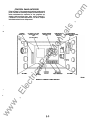
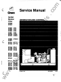
Service Manual
c
ua
ls
GenSet
Models:
DFEB
DFEC
DFFA
DFFB
KTA12
tM
.i;;
KTI11
KTI12
1
I
I
tri
DFGA VTA1
DFGB VTA2
DFGC VTA3
-�
lP
c
•
NT4
NT4
NT5
NT6
NTA2
NTA3
ca
· ·
DFBC
DFBD
DFBE
DFBF
DFCB
DFCC
ar
DFAA
DFAB
DFAC
an
GENERATOR AND CONTROL
KTA31
KTA32
KTA33
DFLA
DFLB
DFLC
DFLD
DFMA
DFMB
KTA51
KTA52
KTA53
KTA54
KTI51
KTT52
w
.E
lec
DFJA
DFJB
DFJC
DFJD
ww
·c
Printed U.S.A.
960-0504
4-93
w
ww
.E
tri
lec
an
tM
ar
lP
ca
ua
ls
.c
om
1
PAGE
TITLE
SAFETY PRECAUTIONS
INTRODUCTION
•••••••••••••••••••.•••••••••••••••••••••••••••••••••••••••••••••••••••••••.••••••.••••••••••••••••••••••••••••••••••••••••••
About th is Manual ....... ........................... ........................ ......... .. ..... . . ..... ............ .......... .. ..... .... ..
Te st ECJ,Iiprnert . . .. . .. ....... .. . . . .. . . . . .. . . .. .. . ........ .. . . . .. . . . . .. ... . ..... .. . . . . .. . . . ... . ........ ...... .... ... . . . . ........... .. . .. ... . . . .. ......
How to C>btain Service . . .. . . ..... .. ............. .. . . . . .. . ......... .. . . . .. . . .. .. . . .. .. . . ........ .. . . . . .. . . .. .. . . . . .. . ..... ... .. .. .. .. . ....... ....
Co rtrols and Generators Ove rview .....................................................................................................
.
2
.
.
.
.
..
.
.
CONTROLS
.
.
..
General ..................................................................................................... ..............................................
Control Descriptions . .. . . . . .. .. . . ... .. ... . .. . .. . . . .. . . . ... . .. ... . . . . .. . . . . .. . ........ ...... .. . . .. .. . . . .. .. . . .. . . . . .. . .. . .. ... . .. ......... ... . . ...
Control Panel Interior ............ .............. . .. . .. .......... . ......... . ....... ..... .. ......... . ...... ....... ... . ....
Ge nSet ()peration ...... ........................................................................... ......... ................... .....................
.
.
. .
... .
.
. .
.. .
GENERATOR
.
.
.
. .
.
..
.. .
..
Gene rator De scriptions . . .. . . . ....... ...... .. . . . . .. .. .. .. . . . .. . . . . .. . . .. .. .. . . ... . . . .. . . . . .. . . . .. . . . . ... . . . .. . . ........ ...... .. . . . .. . . ...... ....
Generator Control Co l11l0 nents .................................... ........ ................ . ........ ... . ...... ............ . ...
Generator ()peration .............................................................................................................................
Optional C ira.Jit Breaker .................. ......................................................................................................
an
3
.
TROU BLESHOOTING
5
COMPONENT TESTS AND ADJUSTMENTS
General
.
.
.
. .
.
tM
4
.. ..
.
...................................................................................................................................................
ii
1-1
1-1
1 -1
1-2
2-1
2-1
2-3
2-6
3-1
3-2
3-3
3-4
4-1
ar
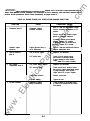
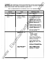
General ....................................................................................... ............................................................ 5-1
Control Components
Engine Co rtrol M oritor (ECM) ............................................................................................................. 5-1
Run Rel ay ....................................................................................................... ........................................ 5-3
Interface Relay Mock.des ............... ........... .. ......... . ....... ..... ..... . ..... ....................................... 5-4
lime Delay Sta rVStop M odule . .. ........... ............. ............. ................. ................................................. 5-5
AC Meters and Current Transfo rmers ................................................................................................. 5-5
Generator Components
Automatic Vol tage R egulator................... ............................................................................................. 5-6
Generator ()peration Review ... ............ ................ .. ........ ..... ...... . ...... .......... ......... ....................... 5-8
Over/Under Voltage Sensor M odule.................................................................................................. 5-10
Over/Under Frequency Sensor M od.lle. ......................................... .................................... ............... 5-10
Overspeed (FreCJ,�e ncy Detection) M odule .................. ............... ..................................................... 5-10
Rotating Rectifier Asse nt>ly .. ... . . ... . . . . .. . . . . ... . . . .. . . . . .. ... . .. . . . . . . . . . . .. . . . . .. . . . . .. . . . . .. . . . .. . . . . . .. . . . .. . . . ... . . . . ... . . ... . . . . .. 5-1 1
Pe rma nent M agnet E xdter ............ .. ............. .......................... ..................... ....................................... 5-1 1
E xdter Rotor ...... ....................... ............................. ............ ......... ............ ... .......... ................................ 5-1 2
E xdter Stator . . .. . . . . .. . .. . .. . . . . . ... ... . . . . .. . .. ...... .. . . . . .. . . . .. . . . . .. . . . . ... . . . .. . . . .. . . . . .. . . . . .. . . . .. . . . . .. . . . . .. . . . .. . . . . .. . . . . .. . . . .. . . . . .. 5-1 2
Ge nerator Rotor................................................................................................................................... 5-1 2
Ge nerator Stator . .... ......................... .. .. ........... ........... ............. ....... .. ... .. ........ .......... ... .. . . ........ ............. 5-13
Reconnection ... .... ............. ......... ............. ........... ... . .. ............ ... ................... ..... ......................... 5-14
Engine Components
Electro nic Governor............................................................................................................................. 5-1 6
Batteries ...... .................. .......... .. ....... ........ ........... ......... .......... ....... .......... ....... .. . ............... ................... 5-1 7
Batte ry Cables . . .. . . . . .. . . . . .. . . . . . . . . . . .. . . . . .. . . . .. . . . . .. . . . . ... . . . .. . . . . .. . . . . . . . . . . .. . . . .. . . . . . . . . . . .. . . . . .. . . . . .. . . . . .. . . . .. . . . . .. . . . . . . .. . . .. 5-1 7
Alternator ........... .............................................................. ................................................................... 5-18
Starter Solenoid . . . . . . . . .. . . . . .. . . . . .. . . . .. . . . . .. . . . . . . . . . . .. . . . .. . . . . .. . . . . . . . . . . .. . . . .. . . . . .. . . . . .. . . . . .. . . . . . . . . . .. . . . . .. . . . . .. . . . . . . . . . .. . . . . .. 5-18
Fuel Solenoid .... .. ........ ........... ......... .. .. .............. .......... ... ...... ..... .. . ......... .......... ...... ............ .. ............... .. 5-18
Control Switch .. .... .......... .. ... ........ ... ........ ... . . . ............ ..... .. . .. ....... ..... .. . . ........ ......... .... ... .. ...... ... . .. . . . .... .... 5-18
Other Optional Components
Testing AC Load Ci ra.Jit Breaker ..... ... ............ .......... ....... .. . . ...... .. ...... .. .. ....... ...... .. .... .. . . . .... .. .. . . . . ... . . . .. 5-1 8
...
.
.
.....
. ..
..
..
. ..
.
lP
.
...
.
ca
...
.
.
.
.
tri
.
lec
.
.
.
..
.
.
..
.
.
.
.
.E
.
.
.
.
GENERATOR
7
Generator Disassembly ............................................................................. ............................................ 6-1
Generator Reasse nt>ly ........ .. .......... .. .......... .. ......... ...... ........... ....... .. . .. .. . . . ... .. . . .. .......... .. .. .. .. ..... .......... .. 6-7
WIRING DIAGRAMS/SCHEMATICS
Refer to Section Usti ng
w
6
ww
..
.
ua
ls
SECTION
.c
om
Co nte nts
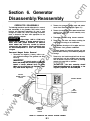
DISASSEMBLY/REASSEMBLY
•.•.••••...•.•••••••...•.•••....•••••....••••.•...••.....•••••...•••
.c
om
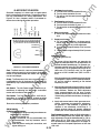
Safety Precautions
Safe and efficient operation can be
achieved only If the equipment Is properly oper
ated and m aintained. Many accidents are caused
equipment.
by failure to follow fundamental rules and precau
tions.
•
Be sure all fuel supplies have a positive shutoff
valve.
•
Do not smoke while servicing lead acid batter
ies. Lead acid batteries emit a highly explosive
hydrogen gas that can be ignited by electrical
arcing or by smoking.
EXHAUST GASES ARE DEADLY
The following symbols, found throughout this man
ual, alert you to potentially dangerous conditions to
the operator, service personnel, or the equipment.
•
hazards which will result In severe persona/ In
jury or death.
tM
Do not use exhaust gases to heat a compart
ment.
•
Be sure the unit is well ventilated.
MOVING PARTS CAN CAUSE SEVERE
PERSONAL INJURY OR DEATH
lP
FUEL AND FUMES ARE FLAMMABLE
Provide an adequate exhaust system to prop
erly expel discharged gases away from en
closed or sheltered areas and areas where in
dividuals are likely to congregate. Visually and
audibly inspect the exhaust daily for leaks per
the maintenance schedule. Ensure that ex
haust manifolds are secured and not warped.
ar
lA CAUTION I This symbol refers to a hazard or un
safe practice which can resultIn persona/Injury
or product or property damage.
ca
Fire, explosion, and personal injury or death can re
sult from improper practices.
•
Keep your hands, clothing, and jewelry away
from moving parts.
•
Before starting work on the generator set, dis
connect starting batteries, negative (-) cable
first. This will prevent accidental starting.
DO NOT fill fuel tanks while engine is running,
unless tanks are outside the engine compart
ment. Fuel contact with hot engine or exhaust
is a potential fire hazard.
•
Make sure that fasteners on the generator set
are secure. Tighten supports and clamps,
keep guards in position over fans, drive belts,
etc.
•
DO NOT permit any flame, cigarette, pilot light,
spark, arcing equipment, or other ignition
source near the generator set or fuel tank.
•
•
Fuel lines must be adequately secured and
free of leaks. Fuel connection at the engine
should be made with an approved flexible line.
Do not use copper piping on flexible lines as
Do not wear loose clothing or jewelry in the vi
cinity of moving parts, or while working on elec
trical equipment. Loose clothing and jewelry
can become caught in moving parts. Jewelry
can short out electrical contacts and cause
shock or burning.
lec
tri
•
.E
•
copper will become brittle if continuously vi
brated or repeatedly bent.
If adjustment must be made while the unit is
running, use extreme caution around hot mani
folds, moving parts, etc.
w
ww
..
an
t!'J•t!UM#!;I This symbol warns of Immediate
lAWARNINGlTh/s symbol refers to a hazard or un
safe practice which can result In severe per
sonal injury or death.
ua
ls
Before operating the generator set, read the Op
erator's Manual and become familiar with it and the
ii
r
•
•
•
Remove electric power before removing pro
tective shields or touching electrical equip
ment. Use rubber insulative mats placed on
dry wood platforms over floors that are metal or
concrete when around electrical equipment.
Do not wear damp clothing (particularly wet
shoes) or allow skin surface to be damp when
handling electrical equipment.
heat exchanger pressure cap while the engine
is running. Allow the generator set to cool and
bleed the system pressure first.
•
have been identified by some state and federal
Use extreme caution when working on electri
toxicity.
fumes, or contact gasoline.
Follow all applicable state and local electrical
codes. Have all electrical installations per
formed by a qualified licensed electrician. Tag
open switches to avoid accidental closure.
•
Used engine oils have been identified by some
state or federal agencies as causing cancer or
reproductive
tM
DO NOT CONNECT GENERATOR SET DI
RECTLY TO ANY BUILDING ELECTRICAL
SYSTEM. Hazardous voltages can flow from
the generator set into the utility line. This cre
ates a potential tor electrocution or property
damage. Connect only through an approved
isolation switch or an approved paralleling de
vice.
When checking
or
changing engine oil, take care not to ingest,
Provide appropriate fire extinguishers and in
ar
•
stall them in convenient locations. Consult the
local fire department tor the correct type of ex
lP
tinguisher to use. Do not use foam on electri
ca
High voltage acts differently than low voltage.
Special equipment and training is required to
work on or around high voltage equipment.
cal fires.
Use extinguishers rated ABC by
NFPA.
•
Make sure that rags are not left on or near the
engine.
•
Operation and maintenance must be done
only by persons trained and qualified to work
on such devices. Improper use or procedures
will result in severe personal injury or death.
Remove all unnecessary grease and oil from
tri
the unit.
Accumulated grease and oil can
cause overheating and engine damage which
lec
present a potential fire hazard.
•
Do not work on energized equipment. Un
authorized personnel must not be permitted
near energized equipment. Due to the nature
of high voltage electrical equipment, induced
voltage remains even after the equipment is
disconnected from the power source. Plan the
time tor maintenance with authorized person
nel so that the equipment can be de-energized
Keep the generator set and the surrounding
area clean and tree from obstructions.
Re
move any debris from the set and keep the
floor clean and dry.
.E
•
toxicity.
breathe the fumes, or contact used oil.
HIGH VOLTAGE GENERATOR SETS
(1.9kV to 15kV)
•
When checking, draining or adding
gasoline, take care not to ingest, breathe the
an
•
Benzene and lead, found in some gasoline,
agencies as causing cancer or reproductive
cal components. High voltages can cause in
jury or death. DO NOT tamper with interlocks.
•
Coolants under pressure have a higher boiling
point than water. DO NOT open a radiator or
ua
ls
•
.c
om
GENERAL SAFETY PRECAUTIONS
ELECTRICAL SHOCK CAN CAUSE
SEVERE PERSONAL INJURY OR DEATH
•
Do not work on this equipment when mentally
or physically fatigued, or after consuming any
alcohol or drug that makes the operation of
equipment unsafe.
ww
w
and safely grounded.
KEEP THIS MANUAL NEAR THE GENSET FOR EASY REFERENCE
iii
LS-10
w
ww
.E
r
tri
lec
an
tM
ar
lP
ca
ua
ls
.c
om
Introduction
ABOUT n-tiS MANUAL
r�lar maintenance schedule is important to obtain
longer unit life, better performance, and safer operation.
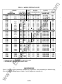
This manual provides troubleshooting and repair informa
tion regarding the controls and generators used on the
following generator sets.
ua
ls
For proper replacement parts identifiCation, refer to ap
propriate Parts Manual supptied with urit.
Repair of printed circuit board components other than
fuses requires well-trained, quatified personnel with the
proper equipment; repair of the printed circuit boards is
not recorrmencled except by the factory. Applcation of
meters or hot soldering irons to printed circuit boards by
other than qualified personnel can cause unnecessary
and expensive damage.
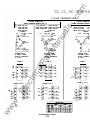
GENERATOR SET
MODEL
DESIGNATIONS
DFAA
DFAB
DFAC
1 75
200
220
200
230
250
NT4
NT4
NT4
NT5
1 75
1 75
200
220
200
200
230
250
DFBF
DFCB
DFCC
NT6
NTA2
NTA3
250
275
31 0
275
300
350
DFEB
DFEC
DFFA
DFFB
KTA1 2
330
400
400
450
DFGA
DFGB
DFGC
VTA1
VTA2
VTA3
DFJD
DFLA
DFLB
DFLC
DFLD
DFMA
DFMB
High voltage testing or high
potential (or Megger) testing of generator windings
can cause damage to solid state components. Isolate
these components before testing.
For any operation, maintenance, or troubleshoodng Information
beyond 1he scope of this manual, refer to oth• manuals received
with unit, or contact your distributor.
lP
400
450
450
500
ca
KTA31
KTA32
KTA33
.E
lec
DFJC
440
KTA51
KTA52
KTA53
KTA54
KTT51
KTT52
500
600
620
660
800
900
750
800
900
1 000
900
1 000
1 1 00
1 250
1 1 20
1 200
1 1 00
1 280
•
•
•
•
•
•
Battery Hydrometer
Tachometer or Frequency Meter
Jurf1)9r Leads
Wheatstone Bridge or Digital Ohmmeter
Variac
Load Test Panel
Megger or Insulation Resistance Meter
HOW TO OBTAIN SERVICE
!Wiays give the complete Model and Serial number of the
generator set as shown on the nameplate when seeking
additional service information or replacement parts. The
nameplate is located on the side of the generator output
box.
1 250
1 500
I &WARN I NG I
w
For further operation, service, and troubleshooting infor
mation regarding engine components, refer to support
manuals specific to your generator set.
Incorrect service or replacement of
parts can result In severe personal Injury or death,
and/or equipment damage. Service personnel must
be qualified to perfonn electrical and mechanical
service. Read and follow Safety Precautions, on
pages II and Ill.
Study this manual carefully and observe all warnings and
cautions. Be sure to review Safety Precautions. on pages
ii and iii. Using the generator set properly and following a
ww
TEST EQUIPMENT
Most of the test procedures in this marual can be per
formed with an AC-DC rrultimeter such as a Sifi1)SOn
Model 260 VOM or a digital VOM. Some other instruments
to h ave available are:
•
550
tri
DFJA
DFJB
KTT1 1
KTT1 2
I ACAUTION I
ar
DFBC
DFBD
DFBD
DFBE
an
KW RATING
50Hz
60Hz
tM
•
.c
om
1.
Section
1-1
.c
om
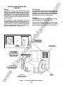
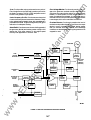
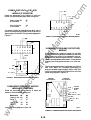
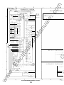
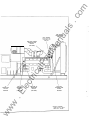
CONTROLS AND GENERATORS
OVERVIEW
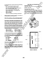
Control Panel
Depending on customer order, the control options and
generator type may differ. Read through this manual to
identify the control options, and generator type. A more in
depth description of the control and generator compo
nents follow in the Controls and Generator sections.
Read this information well and understand the function of
each component.
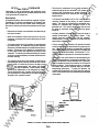
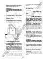
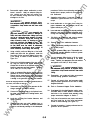
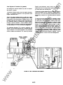
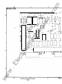
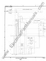
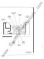
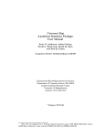
The control panel is mounted inside the front portion of the
generator output box with vibration isolators on both top
and bottom. The controls are separated into a DC panel
for monitoring the engine and an AC panel for monitoring
the generator. See Figure 1 -1 and Section 2.
Generator
ua
ls
General
The generators fitted to this series of generator sets are
a Permanent Magnet Generator (PMG) type.
Also, periodically review this manual and the unit
Operator's Manual when no fault condition is present. You
will want to become familiar with the generator set com
ponent locations, their proper operation and interaction
with other components in order to be effective trou
bleshooting a fault condition, if one occurs.
tM
an
The generators are controlled by an Automatic Voltage
Regulator (AVR). The AVR is mounted on the inside, back
wall of the control panel. See Figure1 -1 and Section 3.
ar
@)
l!J[!J
�
lP
§
[3
t=121!...!:::::=�-_____.!@J:u
CONTROL PANEL
{REFER TO SECTION 2)
.E
lec
tri
OTHER GENERATOR
CONTROL COMPONENTS
(i.e., OVER/UNDER
VOLTAGE AND FREQUENCY
MODULE� ARE LOCATED
INSIDE CONDUIT BOX.
REFER TO SECTION 3.
C===:J
ca
PMG
VOLTAGE
REGULATORS
VOLTAGE REGULATOR
(LOCATED INSIDE
CONTROL PANEL).
REFER TO SECTION 3.
ww
w
AC METERING
CURRENT TRANSFORMERS
(LOCATED INSIDE CONDUIT BOX.)
REFER TO SECTION 2.
PMG
EXCITER
HOUSING
COVE R PLATE
(FOR ACCESS TO ROTATING
RECTIFIER ASSEMBLY)
FIGURE 1-1 . TYPICAL PUG GENERATOR AND CONTROLS
1-2
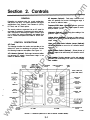
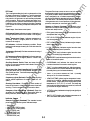
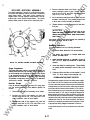
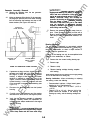
G EN ERAL
AC Ammeter (Optional):
Dual range instrument indi
cates AC generator fine current. Measurement range in
use shown on indcator la"l>5.
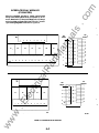
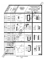
Depending on rustomer order, the control configuration
and options may differ. This section identifies the control
config.uations used; Detector-7 and Detector-12 (NFPA)
DC Panel, and AC Panel options.
ua
ls
Frequency/RPM Meter (Optional): lndcates generator
output frequency in hertz and engine speed in revolu
tions-per-minute (RPM).
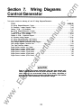
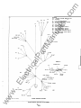
The control panels are separated into an AC panel for
monitoring the generator (if equipped with meter options),
and a DC panel for monitoring the engine. Review F�gure
2-1 to identify the control configuration and options, and
refer to Control Descriptions that follow for further infor
mation .
Wattmeter (Optional): Continuously gives readng of the
generator output in kilowatts.
an
Voltage Adjust (Optional): Rheostat providng approxi
mately plus or minus five percent adjustment of the rated
output voltage.
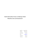
CONTROL DESCRIPTIONS
AC Panel
Upper and Lower Scale Indicator Lamps (Optional):
Indicates which scale to use on the AC voltmeter and AC
ammeter.
tM
The following describes the function and operation of the
optional AC panel for monitoring the generator. Review
the following component descriptions and Figure 2-1 .
Phase Selector Switch (Optional): Selects phases of
generator output to be measured by AC voltmeter and AC
ammeter.
lP
ar
AC Voltmeter (Optional): Dual range instrument indicat
ing generator AC voltage. Measurement range in use
shown on indicator la"l>5.
Field Bteaker: Provides generator exciter and regulator
protection from overheating in the event of an overvoltage
faul condtion.
RUN-STOP-REMOTE
SWITCH
RESET, J_AY) TEST,
PAtEL J_AY) SWITCH
tri
AC
VOLTMETER
PANEL
LAMP
ca
01.. PI£SSURE
GAUGE
.E
lec
INDICATOR
LAMPS
\
AC
AMMETER
---���-lr--r--
PHASE
SELECTOR
SWITCH
COOlANT
TEMPERATURE
GAUGE
RI.JN.IING TM:
METER
w
FREQUENCY/RPM
METER
TACHOMETER
WATIMETER
ww
..
.c
om
Section 2. Controls
OTHER
OPTIONAL
METERS
DC PANEL
AC PANEL
FIGURE 2·1. CONTROLS (DETECTOR-12 AND AC METER OPl10NS SHOWN)
2-1
OR.. TEMPERATURE
GAUGE
ES-181111-1
.c
om
DC Panel
The green Run lamp comes on as soon as both primary
and secondary starter circuits are opened after unit starts.
The yellow pre-alarm lamps indicate that engine oil pres
sure is marginally low, or coolant temperature is margin
ally high, and should be attended to when the generator
set is shut down. The red fault lamps indicate a shutdown
of the generator set for low oil pressure, high engine tem
perature, overspeed, or overcrank fault condition.
The following describes the function and operation of the
DC panel components. The Detector-? panel is standard,
and Detector-1 2 panel includes options to more effec
tively monitor the generator set and ancillary equipment
during operation. Both controls include pre-alarm moni
toring to infonn the operator that a shutdown might occur
if attention is not given to an aspect of engine operation
soon. Review the following component descriptions and
Figure 2-1 .
Oil Pressure Gauge: Indicates pressure of lubricating oil
in engine (wired to a sensor unit located on the engine).
•
Water Temperature Gauge: Indicates temperature of
circulating coolant in engine (wired to a sensor unit
located on the engine) .
•
•
PRE LO OIL PRES (yellow) indicates engine oil pres
sure is marginally low.
PRE HI ENG TEMP (yellow) indicates engine temper
ature is marginally high.
LO OIL PRES (red) indicates engine has shut down
because of critically low oil pressure.
tM
DC Voltmeter: Indicates the battery condition. Proper
reading should be approximately 26 to 28 volts when set
is running.
RUN (green) lamp comes on when both starter circuits
are opened after unit starts.
an
Panel Lamp: Illuminates control panel.
ua
ls
Detector-12 Control {Optional): The optional control
panel has a 1 2 lamp monitoring system. The following de
scribes each lamp function.
•
Tachometer(Optlonal}: Provides constant monitoring of
engine r/min.
HI ENG TEMP (red) indicates engine has shut down
because of critically high temperature.
ar
•
Oil Temperature Gauge (Optional): Indicates tempera
ture of lubricating oil in engine (wired to a sensor unit
located on the engine) .
lP
•
Run-Stop-Remote Switch: Starts and stops the unit
locally, or from a remote location that is wired to the control
engine monitor board.
ca
•
tri
Reset, Lamp Test, Panel Lamp Switch: Resets the fault
circuit only when the Run-Stop-Remote switch is in the
Stop (Reset) position. Tests fault lamps and turns on the
control panel lamp.
Frequency A djust (Optional): Potentiometer providing
engine speed adjustment to achieve proper AC fre
quency.
•
•
lec
•
Running Time Meter: Registers the total number of
hours the unit has run. Use it to keep a record of periodic
servicing. Time is cumulative; meter cannot be reset.
.E
Emergency Stop Pushbutton (Optional): Stops the
generator set immediately when depressed. Must be
reset (pulled out) before restarting generator set.
•
•
Indicator Lamps
RUN (green)
PRE LO OIL PRES (yellow)
PRE HI ENG TEMP (yellow)
LO OIL PRES (red)
HI ENG TEMP (red)
OVERCRANK (red)
OVERSPEED (red)
ww
•
w
Detector-7 Control (Standard): The standard control
panel has seven monitor system indicator lamps.
•
•
•
•
•
•
2-2
OVERSPEED (red) indicates engine has shut down be
cause of excessive speed.
OVERCRANK (red) indicates the starter has been
locked out because of excessive cranking time.
FAULT 1 (red) an undedicated fault. May be program
med as a timed or non-timed shutdown or fault light only
(normally factory set for timed shutdown).
2 (red) same features as Fault 1 (nonnally
factory set for non-timed shutdown) .
FAULT
LOW E N G TEMP (yellow) engine temperature is mar
ginally low for starting. Indicates possible inoperative
coolant heater. Lamp lights when engine water jacket
temperature is 70° F (21 o C) o r lower. The lamp may
stay on during initial generator set operation, but should
go out after the engine warms up.
LO FUEL (yellow) indicates fuel supply is marginally low
(if equipped).
SWITCH OFF (flashing red) indicates generator set is
not in automatic start operation mode.
'
.c
om
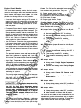
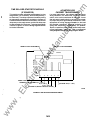
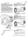
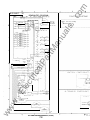
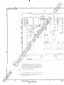
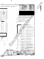
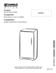
CONTROL PANEL INTERIOR
AUTOMATIC VOLTAGE
REGULATOR (AVR)
VR21
(SEE SECTION 3)
ENGINE CONTRa.
MONITOR (ECM)
A11
TIM: DELAYED
START/STOP
MODULE
A15
OVERSPEED
(FREQUENCY DETECTDI)
MODULE
w
.E
lec
FIGURE 2·2. CONTROL PANEL INTERIOR
ww
(]
DC PANEL
tri
ACPANEL
ca
lP
ar
tM
an
TERMINAL
BOARDTB21
ua
ls
Refer to Figure 2-2 for component locations inside control
panel. Review the following component descriptions to
better understand the operation of the generator set
should a fault condition occur. Also refer to Section 5,
Component Tests and Adjustments, for more in-depth
information about these components.
2-3
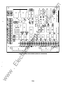
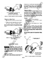
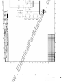
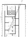
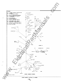
Fuses: The ECM has five replaceable fuses to protect it
from overloads and ground fautts. They are:
This circuit board assembly oontains the basic OOillJO
nents for normal engine start-up and shutdown, terninals
for remote oontrol interoonnection, plug-in oonnectors for
option modules and engine sensor i'l'l)ts. The ECM
provides the following functions of unit protection:
•
Overcrank - Umits engine cranking to 75 seoonds. H
engine fails to start, the module lights a fautt lamp and
opens the cranking circuit . This cycle cranking circuit al
lows three 1 5-seoond cranking cycles with two 1 5-sec
ond rest periods.
Starter solenoid circuit, 20 amps
Fuel solenoid (switched B+) circuits, 20 amps
Continuous B+ out to remote circuits, 1 5 amps
ECM circuits, 5 amps
Engine guage circuits, 5 amps.
Overspeed - Shuts down the engine immediately if an
overspeed oondition occurs and lights a fautt lamp. The
generator sets are equipped with an overspeed (fre
quency detection) module, inside the oontrol panel. The
module is factory set to shut down the generator set at
approximately 21 00 r/rnin (60 Hz units), or 1 850 r/min
(50 Hz units). Refer to Component Tests and Adjust
ments section for further information.
ua
ls
Function Selection Jumpers: The ECM has six selec
tion jumpers that can be repositioned to provide the
following timed or non-timed warnings or timed or non
timed shutdowns with warnings:
W1 Jumper Position ijurrper W8 must be in the B posi
tion):
Non-timed warning under FLT 2 oonditions.
Non-timed shutdown and warning under FLT 2
conditions.
C Timed warning under FLT 2 oonditions.
D Timed shutdown and warning under FLT 2 oon
ditions.
A
B
an
•
F1
F2
F3
F4
FS
Low Oil Pressure - Shuts down the engine immediately
tM
•
.c
om
Engine Control Monitor
if oil pressure drops below 1 4 psi (97 kPa) and fights a
W2
fautt lamp. The fautt is inhibited during cranking and
time delayed about 1 0 seoonds following starter disoon
nect. The delay allows oil pressure to rise to normal
before the electronic oontrol module monitors this
system.
Jumper Position ijumper W9 must be in the B posi
tion):
Non-timed warning under FLT 1 oonditions.
Non-timed shutdown and warning under FLT
conditions.
C Timed warning under FLT 1 oonditions.
D Timed shutdown and warning under FLT 1 oon
ditions.
ar
A
B
W6 Jumper Positio n:
ca
High Engine Terrperature - Shuts down the engine
immediately if coolant terrperature rises above 21 5° F
(1 02° C) and lights a fautt lamp. The fautt is inhibited
during cranking and time delayed about 1 0 seconds fol
lowing starter disconnect. This delay allows coolant in
a hot engine time to circulate and return the water jacket
to normal before the electronic control module resumes
monitoring this system.
tri
•
lP
The pre-low oil pressure sensor and lamp provides an
alarm that oil pressure is marginally low, 20 psi (1 38
kPa) or less. The cause should be found and oorrected
as soon as possible.
Warning under Pre-Low 011 Pressure oonci
tions.
B Shutdown and warning under Pre-Low Oil Pres
sure oonditions.
.E
lec
A
W8 Jumper Position:
I ACAUTION I
T1Je high engine tempetatute shut
down system will not operate N the coolant level Is
A
B
too low. The high engine temperatute sensor
monitors coolant temperatute. Loss of coolant will
prevent sensor operation and allow the engine to
ovelheat causing severe damage to the engine.
TJJerefote, maintain adequate coolant level to en
sure the operation of the high engine tempetatute
shutdown system.
Warning during standby under FLT 2 oonditions.
Allows selection of functions with W1 jumper.
W8 Jumper Position:
A
B
w
ww
Low Coolant Level Shutdown (Optional) - A soHd-state
sensor installed into the radiator provides engine shut
down if coolant level falls too low. It also lights the high
engine temperature fautt lamp.
Warning under Pre-High Engine Temperature
co nditions.
B Shutdown and warring under Pre-High Engine
Temperature oonditions.
A
W7 Jumper Position:
The pre-high engine temperature sensor and lamp pro
vides an alarm that engine terrperature is marginally
high, 205° F (97° C) or higher. The cause should be
found and oorrected as soon as possible.
•
1
Warning during standby under FLT 1 oonditions.
Allows selection of functions with W2 jumper.
The ECM also has solder finks and rectifiers that can be
repositioned to provide other functions such as: negative
signal mode, 1 OS second cycle cranking, 75 seoond non
cycle cranking and 60 seoond non-cycle cranking.
2-4
.c
om
0
0
I
2
3
4
5
6
P
4
ar
tM
an
ua
ls
7
-
";"
]"
P
11
11
1
9a..__s_7 _s_:_•�-1_12 ,_1 _2_ _
/
ca
O
lP
TBI
1
tri
.......
lJIII oc
TEST
IIESET
115
... LO
1
_, '"""
6
s
.... "' :.:..o..
N
r--
4P2 3
ww
w
.E
lec
RGURE 2-3. ENGitE CONTROL MONITOR (DETECTOR 12 ECM SHOWN)
2-5
2
1
.c
om
GENSET OPERATION
Run Relay(s) (K11)
This relay (may be up to three) provides wiring connec
tions for external functions of the site installation that are
to be controlled by the starting and/or stopping of the
generator set such as ventilation air louvers, blowers, etc.
The sets of contacts in the relay base provide for either
closing a circuit or opening a drcuit upon energizing and
de-energizing the relay (depending on the desired func
tion wires to the base connections). The relay is energized
when the generator set run circuitry is energized (ie., fuel
solenoid) when connected to the ECM at TB1 -1 0
(switched B+ connection).
Because of varying control option combinations, the fol
lowing operating descriptions will encorrpass a Detector1 2 controller with full options. Read the information
through to Emergency Shutdown to gain a full under
standing of the options and how they interact with the
engine control monitor (ECM).
ua
ls
Regardless of the controller model you have, the ECM in
cludes the shutdown fault commands. Controllers with
options provide delineation and pre-alarm of the shut
down faults, time delayed starting and stopping, and
additional monitoring/control, but all engine operation
commands through these options are still controlled
through the ECM.
Interface Relay Modules (A13, A14)
These relay modules are used in conjunction with the
Detector ECM's to provide external monitoring of the en
gine-generator at customers control panel. As add-on
circuit boards, they interface with the remote annunciator
signals from the ECM and allow the use of either AC or DC
for alarm drives. The relays are configured for low side
switching by the control and supply sets of contacts for
external alarm connections.
an
Starting Sequence
Manual: The starting sequence is initiated by placing the
ar
All units equipped with AC meters have current transform
ers installed inside the conduit box through which the cus
tomer can route the load leads.
tM
Current Transformers (Not shown)
If you are reviewing this operation information for trou
bleshooting purposes, make sure you have elininated all
other malfunction checks external of the controls prior to
troubleshooting the printed drcuit board type compo
nents of the controller. Also review the Generator section
for generator related control components and Corrpo
nent Tests and Adjustments section for more in-depth
information. Refer to appropriate DC Schematic - Ladder
Diagram in Wiring Diagrams section when reviewing the
following information.
Automatic Voltage Regulator (VR21)
Run/Stop/Remote switch (S1 2) in the Run position.
Refer to section 3 for more information.
Placing switch S1 2 in the Run position energizes the ECM
Run Relay (1<7). By energizing K7, B+ is supplied through
the electrical circuits of the ECM to energize the engine
run circuits (i.e., fuel solenoid) and front panel gauges and
the starter solenoid (through K3).
lP
Overspeed (Frequency Detection) Module
This rnc::KiJie derives a speed (Hz) signal from the PMG,
ca
but is powered from the generator set battery. A small time
delay, typically one second, is incorporated in the over
speed function to allow for engine overshoot. The module
contains two adjustable potentiometers, Overspeed and
Crari<ing (the cranking potentiometer is not used how
ever). Refer to Section 5 for more information.
tri
The engine cranking period is detemined by the Over
crank Timer and Cycle Crank Driver (U1 ). and the Cycle
Crank Relay (K1 2), whic h co ntrol energizing and de
energizing the Power Relays K2 and K3 that supply cur
rent to the on-set starter and fuel solenoids.
Tlme Delayed Start/Stop Module (A15)
This module provides time delays for starting and stop
ping the generator set as follows:
.E
lec
Automatic: Wrth the Run/Stop/Remote switch (S1 2) in
Remote position, a remote start command (closure of on
site, dry contacts) to the generator set controller (B+ to
remote) activates the Time Delayed Start/Stop Module
(A1 5), which initiates its time delay start period.
Delayed Stanlng: The time delay start function is to
preclude automatic start-up of the generator set for a de
temined amount of time (adjustable from 1 to 1 5 sec
onds) for installations that night experience power inter
ruptions of short duration, and therefore not want the gen
erator set starting.
Upon completion of the ti me delay start period, the ECM
initiates engine cranking and start-up by energizing Run
Relay (1<7) as described in manual start-up.
Delayed Stopping: The time delay stop function is ad
justable from 1 to 1 5 minutes to provide for automatic
cool-down running of the engine for prescribed amount of
time (approximately 3 to 5 ninutes is recommended).
w
When engine successfully crari<s and starter discon
nects, input signals from either start disconnect system of
the ECM 'Nill activate the Start Disconnect Relay of mod
ule A1 5 (K1) which enables the module for Time Delayed
Stop mode.
Control cabinet Heater
ww
A control cabinet heater provides a means of hunidity/
temperature control of the control box interior to protect
the COJ"ll)Onents and assist their effectiveness when the
generator set is subjected to varying ambient conditions
during extended periods of non-use. The element is con
trolled by an adjustable thermostat.
2-6
.c
om
After the starter disconnects, the LOP and HET fault
shutdowns will remain inhibited for another 1 0 seconds to
allow oil pressure and engine temperature to stabilize
within the operating range.
During generator set operation, all safety systems func
tion to protect and monitor set operation. At end of the
generator set duty cycle, when generator output is discon
nected from load and the remote run signal is discontin
ued, the time delayed stop function of module A15 will
continue the engine-generator run time for the prescribed
engine cool-down period of 3 to 5 rrinutes before deacti
vating the run circuits of the ECM.
Normal Operating Parameters
After a successful engine start-up, with all conditions
satisfied, the engine will gain in speed to governor con
trolled operation. Should the engine go into an overspeed
condition, either an Over/Under Frequency Sensor, an
Overspeed Module, or a mecharical overspeed switch
(depending on generator type and options ordered) will
ground the overspeed input circuit to the ECM to cause a
shutdown and fight the Overspeed fault lamp. After the
problem is corrected, starting will not occu r until the Reset
switch is pressed.
ua
ls
Starter-Disconnect Parameters
This type of control uses two means of starter-disconnect
in order to protect the starter in the case one means
should fail. The first uses a DC relay (K14); a B+ signal
taken from the battery charging alternator in most cases
energizes the relay to disconnect the starter. The second
method uses an AC relay (K10); voltage from the genera
tor energizes this relay to provide a back-up to the DC
relay. The control uses this method to provide uninter
rupted generator set operation even if only one means of
start disconnect is operational. However, the local Run
lamp does not Hght unless both start disconnect relays
operate. H the generator set is equipped with a remote
Run lamp, the operator can then deterrrine which means
of start disconnect has failed for such an occurrence. H the
remote Run lamp lights (and the local Run lamp does not),
the DC relay is not functioning.
an
Continuous operation of the generator set also depends
on the proper oil pressure and engine temperature being
maintained, and also any customer required fault condi
tions connected to the ECM.
tM
Stopping Sequence
Placing the Run/Stop/Remote switch to the Stop position
de-energizes Run Relay (K7) which opens the current
supply through the ECM (K2) to de-energize the genera
tor set mounted fuel solenoid (stops fuel flow which stops
the engine).
ar
High Engine Temperature (HET) and Low Oil Pressure
(LOP) faults are time delayed about 1 0 seconds following
starter disconnect and inhibited during cranking. This
allows the coolant in a hot engine some time to circulate
and return the water jacket to normal temperature before
the ECM begins to monitor this parameter. It also allows
the oil pressure to build to normal before monitoring this
system. Following this delay, these faults beoome imme
diate shutdowns for engine protection.
ca
lP
Emergency Shutdown
lec
tri
H conditions are correct, the engine will start and the
starter will disconnect. H not, an overcrank fault occurs by
U1 having cycled/timed out through drive transistor U4 to
energize Fault Relay K6, which opens the start drcuit of
the ECM. The Reset switch (S1 1) must be pushed to clear
the fault before attempting to restart.
Start-Disconnect Sequence
ww
w
.E
When the generator set starts, output voltage from the DC
alternator energizes Start-Disconnect relay K14. Energiz
ing K14 then closes its N .O. contacts whic h lights the
control panel Run lamp. Also, when the generator set
starts, output voltage from the generator stator energizes
Starter-Disconnect relay K1 0. Energizing K10
then
closes its N.O. contacts and lights a Remote Run lamp (If
equipped).
2-7
The K6 fault relay is energized when fault sensors re
spond to one of the following fault conditions: overcrank,
low oil pressure, high engine temperature, overspeed,
and over/under voltage/frequency (if equipped). Energiz
ing the K6 fault relay opens its N.C. contacts and closes
its N.O. contacts. Opening the N.C. contacts cisconnects
B+ from the Power Relays K3 and K2. This stops crali<ing
if the engine is being cranked and shuts off the fuel flow.
Closing one of the N.O. contacts of K6 activates the K8
relay which breaks power to the fault interface relays so
that only the indicator associated with the fault will acti
vate. Closing the other N.O. contacts of K6 connects B+
to the remote alann tenninal.
w
ww
.E
tri
lec
an
tM
ar
lP
ca
ua
ls
..
.c
om
.c
om
Section 3. Generator
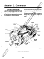
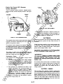
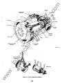
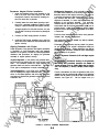
GENERATOR DESCRIPTIONS
An exciter/rotating rectifier assembly is mounted inter
nally to the non-drive-end bearing, while the permanent
magnet exciter is overhung from the non-drive-end bear
ing.
ua
ls
The AC generators are brushless, rotating field type, con
trolled by an automatic voltage regulator (AVA). Perma
nent magnet exciter (PMG) types are used in these series
of generator sets. The AVA of these generator sets is
powered by the permanent magnet pilot exciter which
provides a source of constant excitation power, independ
ent of load changes or load current distortions.
lP
BLOWER
ca
END BEARING
tri
COUPLING
EXCITER
STATOR
ar
tM
an
Removable access covers are provided at each end of the
generators and on each side of the conduit box for
cleaning and inspection, and easy access to the output
terminals and other ancillary equipment. See Rgures 3-1
and 3-2.
.E
lec
ROTATING
RECTIFIER
ASSEMBLY
ROTOR
ENDBRACKETIENGINE
ADAPTOR
ww
w
ROTOR SHAFT
RllG-1115
FIGURE 3-1. TYPICAL PMG GENERATOR
3-1
.c
om
GEN ERATOR CONTROL COMPON E NTS
voHage is over or under the nominal voltage by the
preselected amount (typically 1 0 percent). The module in
cludes an adjustable time delay relay to prevent nuisance
tripping (typically set at 25 percent, or approximately 2.5
seconds). The module and time delay relay are mounted
on a bracket in the generator conduit box.
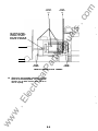
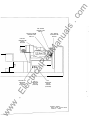
The following briefly describes generator related control
components that affect the proper operation or shutdown
of the generator set. See Figure 3-2 for component
locations.
Automatic Voltage Regulator (AVR)
Over/Under Frequency Sensor Module
The AVR is mounted on the inside back wall of the control
box. Refer to Generator Operation following for further
AVR operation information, and to Component Tests and
Adjustments section for further description and adjust
ment procedure of the AVA.
ua
ls
This is an adjustable frequency-sensitive relay typically
connected to the Engine Control Monitor (ECM) Fault 2
circuit if the Over/Under Voltage module is also installed,
or Fault 1 for overfrequency and Fault 2 for underfre
quency if installed alone, to shut down the generator set
when the output frequency is over or under the nominal
frequency by the preselected amount. (Also, Fault 2 must
be converted for timed shutdown.) The module is
mounted on a bracket in the generator conduit box.
Over/Under Voltage Sensor Module
an
This is an adjustable voHage-sensitive relay typically
connected to the Engine Control Monitor (ECM) Fault 1
circuit to shut down the generator set when the output
tM
@]
(�](!]
VOlTAGE REGULATOR
IS lOCATED INSIDE
CONTROL PANEl, AND
AUXIliARY TERMINAl
BOARD IS lOCATED INSIDE
CONDUIT BOX.
ar
OR
ca
CONTROL PANEl
(REFER TO SECTION 2)
lec
tri
OPTIONAL GENERATOR
CONTROL COMPONENTS
(i.e., OVER/UNDER
VOLTAGE AND FREQUENCY
MODUlES) ARE lOCATED
INSIDE CONDUIT BOX.
lP
PMG
VOLTAGE
REGULATORS
.E
OPTIONAL
CIRCUIT BREAKER
(NOT SHOWN)
IS MOUNTED
ON SIDE OF
CONDUIT BOX.
w
AC METERING
CURRENT TRANSFORMERS
(lOCATED INSIDE CONDUIT BOX.)
REFER TO SECTION 2.
ww
COVER PLATE
(FOR ACCESS TO ROTATING
RECTIFIER ASSEMBlY)
FIGURE 3-2. GENERATOR CONTROL COMPONENT LOCATIONS
3-2
'
.c
om
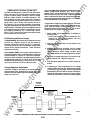
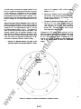
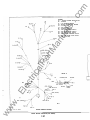
GENERATOR OPERATION
regulator (at auxiliary terminal block). The AVA compares
the main stator output with a reference value and feeds a
controlled excitation current to the main exciter stator.
The AC output of the main exciter rotor is converted to DC
by the rectifier assembly, comprised of six diodes
mounted on two heatsinks to form positive and negative
plates. The diodes ar e protected against harmful over
voltages (caused for example, by switching circuits or
out�f-phase paralleling) by a metal�xide varistor
(MOV). The DC output of the rectifier assembly provides
the excitation onto the main rotor.
tM
an
ua
ls
A permanent magnet generator exciter (PMG), mounted
to the end of the main rotor shaft, provides power by way
of the AVA to the main exciter stator. Excitation power is
therefore independent of output voltage, resulting in
positive voltage build-up, without reliance on residual
magnetism. The main exciter stator mounts in the end
bell, the main exciter rotor and its rotating rectifier assem
bly mount on the rotor shaft. Within the end bell, leads X
(+, positive) and XX (-, negative) from the exciter stator
winding, connect to the output terminals of the voltage
MAlt
STATOR
EXCITER
STATOR
ca
PERMANENT
MAGNET
STATOR
lP
ar
AUTOIMTIC
VOLTAGE
REGU..ATOR
tri
�SHAFT--_.
--1 ��--=---t- I --�--D�
---tEXCITOR
ROTOR
ww
DIODES
RGURE 3-3. GENERATOR OPERA110N DIAGRAM
w
.E
lec
PERMANENT
MAGNET
ROTOR
3-3
MA...
ROTOR
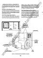
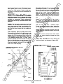
Depending on site specifications and applicable code
requirements, an optional circuit breaker may be mounted
in the generator AC output box.
Description
The thermal trip action of the breaker is accomplished
by bimetal strips. A sustained ove �current con� ition
will cause a thermal reaction of the b1metal and tnp the
breaker. Response of the bimetal is proportional to
current; high current-fast response, low current-slow
response. This action provides a time delay f �r normal
_
such
inrush current and temporary overload cond1t1ons
as motor starting .
The magnetic trip action of the breaker is caus �d by an
electromagnet, which partially surrounds t� e mternal
bimetal strips. If a short circuit occurs, the h1gh current
through the electromagnet will attract the bimetal
armatu re and trip the breaker. Some breaker models
provide front adjustment of the magnetic trip action.
These adjustments are normally set at the factory at
the high position, but provide for individual conductor
settings to suit customer needs.
•
ua
ls
Auxiliary contacts (if equipped) are used for local or
remote annunciation of the breaker status. They
usually have one normally-open and one normally
closed contact (1 form C contacts) to comply with the
annunciator requirement.
an
When an overload or short circuit occurs on any one
conductor, a common trip bar will disconnect all three
conductors.
•
The trip actuator (if applicable) is for periodic exercise
of the breaker to clean and maintain its proper opera
tion. Rotating this actuator mechanically simulates
over-current tripping through actuation of linkages not
operated by the On/Off handle. See Section 5, C�m
_
ponent Tests and Adjustments, for further mformat1on.
Operation of the circuit breaker is determined by site
established procedures. In emergency standby ���tal
lations, the breaker is often placed to the On pos1t1on,
and is intended for safety trip actuation in the event of
a fault condition. If the breaker trips open, investigate
the cause and perform remedial steps per the trou
bleshooting procedures. To close the breaker, the
handle must be placed to the Reset position and then
to On. Refer to Section 4 fortroubleshooting and safety
procedures.
tri
ca
lP
•
•
tM
•
Generator set output is connected to the load through
the circuit breaker.
ar
•
The shunt trip mechanism (if equi J?ped) consists o! a
solenoid tripping device mounted m the ? rea�er w1th
external lead connections for remote s1gnahng. A
momentary signal to the solenoid coil will cause the
breaker to trip.
This feature is available in AC or DC voltages, and is
normally installed at the factory to meet customer
needs. The shunt trip mechanism is most often con
nected to a common fault shutdown circuit of the
generator set. This quickly disconnects the set from
the load on shutdown and avoids a reverse power
condition.
All supplied breakers are thermal and magnetic trip type.
Depending on customer requirements, the breaker may
_
also include shunt trip and remote alarm connections.
Review the following functions/requirements and Figure
3-4.
•
.c
om
•
OPTI ON AL C I RCU IT BREAKER
GENERATOR
ww
w
.E
lec
OUTPUT
BOX
LD
11DE VIEW - HANDLE POIITIONI
SHUNT niP
+COMMON ALAAM
-GROUND
AUXIUAAV
A
,t--.,-�r.•--....- COMMON
8
FIGURE 3-4. TYPICAL GENERATOR-MOUNTED CIRCUIT BREAKER
3-4
4.
.c
om
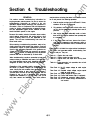
Section
Troubleshooting
GENERAL
analysis before reviewing the tables in this section should
be to ask yourself the following questions:
This section contains troubleshooting information for
engine1Jenerator control systems. Be sure to review the
troubleshooting information as outlined in the unit
Operato(s Manual before performing the procedures in
this section. Refer to Componert Tests and Adjustments
�ion for further engine1Jenerator COrJ1X>nent informa
tiOn and appropriate engine service manuals for adcti
tional information specific to the engine.
ua
ls
1. Was the engine running when it shut down? If it was,
shutdown is not due to overcrank.
2. Did srutclown oca.Jr within one minute after start
up? H it did, the shutdown is probably due to low oil
pressure.
3. Was engine operation noticeably erratic or faster
than usual? If it was, the sh.Jtdown was probably due
to overspeed.
an
Because this section contains information about various
control options, read through this section before a fault
oca.Jrs to identify what is or is not applicable to your
genset. This will save troubleshooting time when the
actual need arises.
4. If the engine starts and runs, observe the oil pres
sure, engine temperature and fre<J.Iency meter or
tachometer until sh.Jtclown oca.Jrs, to determine the
cause.
tM
�etore starting a troubleshooting procedure, make a few
s1rrple checks that migt1 expose the problem. Check all
rt:JOOifications, r�irs, or parts replacements performed
s1nce the last satisfactory operation of the generator set.
A �se or ot�rwise incorrect wire connection, an opened
_
breaker, or a loose plug-in are all potential
switch or curuit
problems that can be eliminated by a visual check.
This section is divided into engine-related troubleshoot
ing tables and generator-related troubleshooting flow
charts to aid you. They are:
ar
Table 4-1. Engine does not crank.
Table 4-2. Engine aanks, but does not start.
Table 4-3. Engine starts, but stops after running short
time.
Table 4-4. Engine-generator is in operation, then a fault
sRrtdown occurs.
lP
When troubleshooting a problem, remember to keep your
problem soMng a methodical and most of all safe proc
ess. Ha&tY decisions can be costly, harmful to your health,
dangerous to others, and may not solve the problem.
ca
Regardless of the cortroller model a generator set has
the basics of problem analysis are fundamertally thfi
same. Identify the fault condition then get specifiC about
the corrective action to take. However, the Detector-7
controller does not have all the lamp indicators that the
Detector-12 has; to aid in identifying other customer
required fault conditions (i.e., low fuel, fault 1 and 2) that
may have caused the sh.Jtdown. Your initial problem
.E
lec
tri
speed.
Flow Chart 4-2. Unstable outJ:U voltage, engine speed
stable at rated speed.
Flow Chart 4-3. Ouq:x.rt voltage too high or low.
Flow Chart 4-4. Exciter field breaker ti1JS (if equipped).
Flow Chart 4-5. Unbalanced generator output voltage.
Flow Chart 4-6. No AC output through set-mounted circuit breaker.
w
ww
Flow Chart 4-1. No AC output voltage at rated engine
4-1
.c
om
I AWARNING I
Atiny troubleshooting procedures present hazards which can result In severe personal Injury or
death. Only qualified service personnel with knowledge of fuels, electricity, and machinery hazards should
perfonn service ptOCedures. Review Safety Precautions, on pages II and Ill.
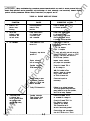
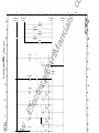
TABLE
SYMPTOM
4-1 . ENGINE DOES NOT CRANK
CORRECTIVE ACTION
CAUSE
Press to desired, Run
or Remote position.
2. Other fault
indicator lafll)S
iluminated, but
no fault exists.
Lamp Reset switch
not actuated after
a previous fault
was remedied.
Press Lamp Reset switch
to de-energize faJit
lalll> relays a ECM, after
Rui'VStop/Rernote switch
is pressed to Stop position.
3.
Fuses blown on ECM
board A1 1 .
Check fuses F1 and F4.
Replace if necessary with
proper fuse:
F1 - 20 Alll>ere
F4 - 5 Alll>9fe
tM
No indication.
an
SWITCH OFF
indictor lamp
flashing.
ua
ls
Run/Stop/Remote
switch in Stop
position.
1.
To reset, pull switch out and move the
RUN/STOP/REMOTE switch to STOP
position. Then push test switch to
RESET!La!ll> position.
Starter solenoid
will not energize.
Inspect starter solenoid
per proper test procedure.
Possible defective
ECM board A1 1 .
Check A1 1 board TB1-9
for B+ voltage in.
tri
ca
lP
ar
Emergency stop button
pushed in.
lec
Broken wi� or poor
comections between
board A1 1 TB1-8 and
starter solenoid.
.E
Fauly ECM board A1 1 .
ww
at TB1 -8 of board A1 1 .
Check and repai" as
necessary.
If there is no voltage between
and ground stud when the
panel switch is in the Run position,
TB1-8
the ECM is faulty. Replace.
Possible defective
lime Delayed Start!
Stop Module
Check A1 5 board TB1-4
for constant B+ voltage in.
A15.
Check A1 5 board TB1-5 for
Run Signal In voltage.
Voltage at A15 board
TB1 -6 should be at B+
at end of start delay period.
w
4. Time delay start
is initiated, but
starter solenoid does
not energize after
desired time delay
period.
With S12 switch in Run
position, check for voltage
out to starter solenoid
4-2
Check wiring and connections
from A1 5 TB1 -6 to A1 1 TB1 -6.
.c
om
�WARNING I
Many troubleshooting procedures present hazards which can result In severe personal Injury or
death. Only qualified service personnel with knowledge of fuels, electricity, and machinery hazards should
pertonn service procedures. Review Safety Precautions, on pages II and Ill.
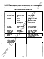
TABLE 4-2. ENGINE CRANKS BUT DOES NOT START
SYMPTOM
Low Fuel larll> also lit.
InsuffiCient fuel in supply
tank.
Fuel solenoid does
not energize.
Fuse blown on ECM
board A1 1 .
ua
ls
Overcrank lamp lit.
Possible defective ECM
board A1 1 .
tM
Broken wiring or poor
oonnections between
board A1 1 TB1-10 and
fuel solenoid.
Fuel solenoid
energizes, but no
fuel flows.
lP
ar
Blockage of fuel supply
system.
�ngine hard to start
due to cold antliert
air te�rature.
Fault shutdown occurs,
but no fault lamp
Short cranking period.
Delective ECM board A 1 1 .
w
.E
lec
Note:
The ECM board A1 1
P.C. board oontrols are
to provide cycle cranking,
but generator set stops
before 1 5 ±3 seoonds.
ww
Check fuse F2. Replace if
necessary. F2 - 20 Arll>ere.
Check for voltage out at TB1 -1 0
when engine is cranking.
Check and rectify as
necessary.
Check fuel supply system
(fuel supply tank, shutoff
valves, lines and connections,
filters and transfer pump, etc.).
Check heater system power
supply, oontrols, etc., and
oorrect as necessary.
Place Rui'VStopiRernote switch
to Stop position, then depress
larll> Test switch to Test position
to check fault lamps.
lamp burned out.
tri
indication.
3.
Heater system not
keeping engine warm.
ca
2.
Fill with oorrect fuel.
an
1.
CORREC11VE ACTION
CAUSE
4-3
Replace ECM (A1 1).
.c
om
I AWARNING I
Many troubleshooting procedures present hazards which can result In severe personal Injury or
death. Only qualified serviCe personnel with knowledge of fuels, electricity, and machinery hazards should
pertonn serviCe pmceclures. Review Safety Precautions, on pages II and Ill.
TABLE 4-3. ENGINE STARTS, BUT STOPS AFTER RUNNING SHORT TIME
CORREcnVE AcnON
1 . Overspeed lafll) lit.
ua
ls
CAUSE
SYMPTOM
Refer to Tests and Adjustments section.
Perform necessary adjustments of O.S.
module.
Overspeed MoWle
initialized shutdown.
an
Perform start-up and monitor engine
speed to overspeed sl'lltdown.
If shutdown occurs before desired
setpoint, readjust O.S. module.
If adjustment does not correct fault
condition, replace o.s. module.
Engine governor faulty or
out of adjustment.
2. Low Oil Pressure
lamp lit.
ar
Low oil level in engine.
lP
LOP switch faulty.
High Engine
Temperature lafll) lit.
HET SWitch is faulty.
Check coolant level, perform restart,
and monitor engine tefll)erature gauge.
If gauge reading is within normal
range, switch S2 is faulty. Replace.
Thermostat defective.
Replace thermostat.
Fan belt slipping.
TJQhten fan belt.
tri
lec
No fault oondition.
Intermittent control
wiring connections.
w
ww
Check oil level, perform restart,
and monitor oil pressure gauge.
If gauge reading is within normal
range, switch 81 is faulty. Replace.
Replenish as necessary.
.E
4.
Replenish as necessary.
Low coolant level in engine.
ca
3.
Refer to Tests and Adjustments section.
Perform appropriate tests.
tM
Unstable engine
operation.
4-4
Check condition of all oontrol wiring
are correct
and seaJre.
to make sure connections
.c
om
�ARNING I
Many troubleshooting procedures present hazards which can result In severe personal Injury or
death. Only qualified service personnel with knowledge of fuels, electricity, and machinery hazards should
perfonn service procedures. Review Safety Precautions, on pages II and Ill.
TABLE 4-4. ENGINE-GENERATOR IS IN OPERATION, THEN A FAULT SHUTDOWN OCCURS
SYMPTOM
CORRECTIVE ACTION
1.
LOP, HET, Overspeed
lamp lit.
As indicated.
2.
Fault 1 or Fault 2
lamp lit.
Over/Under Voltage or
Frequency, as dedicated
by customer.
ua
ls
CAUSE
Refer to Table 4-3.
Refer to Tests and Adjustments section,
and perform necessary adjustments.
Restart unit and monitor gauges.
No fault lamp lit.
Possible defective ECM
board A1 1 .
ca
3.
lP
ar
tM
an
H shutdown was we to over/under
voltage, the voltage regulator may
require adjustment or is faulty. Refer
to Tests and Adjustments section for
adjustments, replace if faulty.
tri
.E
lec
Refer also to generator-related
Flow Charts that follow.
Check fuses F4 and F2 of ECM
board A1 1 .
F4 (Main) 5 Ampere
F2 (Fuel solenoid or
ignition) - 20 Ampere
-
Perform restart and check for B+
voltage in at TB1 -9 and voltage out
at TB1 -1 0 to fuel solenoid.
H there is voltage out at TB1-10,
check fuel supply solenoid, sn.rtofl
valves, etc.
H there is no voltage out at TB1 -10,
ECM boan:f A1 1 is defective. Replace.
Olher aJstomer re<J.Jired
studown conmand.
w
ww
H shutdown was we to over/under
frequency, the engine governor may
require adjustment or is faulty. Refer
to Tests and Adjustments section for
adjustments, replace if faulty.
4-5
Refer to ilstalalion reference
or ooruct your service
represerUiiYe tor assistara.
malerial,
.c
om
[ AWARNING [
Many troubleshOoting procedures present hazants which can result In severe personal Injury or
death. Only qualified service personnel with knowledge of fuels, electricity, and machinery hazants should
pertonn service procedures. Review Safety Precautions, on pages II and Ill.
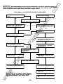
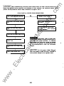
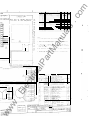
Is field breaker CB21
position?
4-1 . NO AC OUlPUT VOLTAGE AT RATED SPEED
v..
at ON (fuly-in)
,
Repla:e defective field breaker.
No
Remove
one lead from breaker and check
continuity with ohmmeter. Is breaker open?
No
Place breaker swik:h 10 ON position. Does
generator AC OU1pUt voltage buik:t up?
ua
ls
FLOW CHART
v..
If voltage is unstable, high or low, or causes
breaker 10 trip, refer 10 other Flow Char1s.
an
v..
No
v..
Is resid.Jal voltage across TB21-22 and -23
equal to 5 10 10 VAC or more?
tM
Rash exciter field. Does generator output
voltage buik:t up?
No
v..
Is exciter field voltage aaoss VR21-X and
at approximately 24 10 32 VDC?
-XX
No
ca
v..
lP
ar
v..
No
Disconnect slat>!" leads U2 and V2 from
TB21-22 and -23. Is residual voltage across
lhe leads 150 10 250 VAC ro��?
No
Check lead continuity between Auxiliary
Terminal Board (leads 6, 7, and 8) and
TB21-22, -23, and -25.
Check exciter field wiring for shorts.
tri
Replace bad wiring.
Check exciter field wiring for opens.
Check
dodes CR1 lhrough CR6
Replace if bad.
lec
Replace bad wiring.
on
rotH".
.E
Replace voltage regulator VR21.
Check exciter field wincing. Replace if bad.
Check exci& ro10r wincing. Repla:e if bad.
w
Check generaa roo field wincing.
I A CAUTION I
Replace if bad.
ww
Do not replace Voltage Regulator
VR21 until external trouble has been corrected to
avoid possible damage to new regulator boant.
Check generator slaiOr wincings. Replace if
bad.
4-6
.c
om
I AWARNING I
Many troubleshooting procedures present hazards which can result In severe personal Injury or
death. Only qualified service personnel with knowledge of fuels, electricity, and machinery hazards should
perlorm service procedures. Review Safety Precautions, on pages II and IIi.
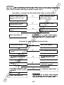
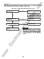
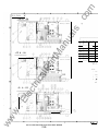
FLOW CHART 4-2. UNSTABLE VOLTAGE, ENGINE SPEED STABLE AT RATED SPEED
Are there any broken wires or loose
connections on voltage regula1Dr assembly?
Does voltage cycle from zero to rated
output?
No
Check wiring harness from regulator
assembly to end bell. Check ok?
I
Yes
Ye.
Check voltage regulator adjustment setting.
Check ok?
I
Repair wiring or
replace as
required.
Is voltage stable within specifications at no
load to full load range of generator set?
I No
/ ACAUTION I
tM
I
No
ua
ls
No
an
I
Repair as required. Check control panel
voltage aqust rheostat and replace if
defective (open).
Ye.
Do not replace Voltage Regulator
VR21 until external trouble has been COtTeCted to
avoid possible canage to new regulator board.
ar
Replace Voltage Regulator VR21 .
l v•
ca
correct rpm?
Is engine running at
lP
FLOW CHART 4-3. OUTPUT VOLTAGE TOO HIGH OR LOW
Are generator output connections correct
Md secue?
tri
(If
lec
R21
IY•
of Voltage Adjust control
equipped) result in correct output
Does aqustment
voltage?
l r•
Check Voltage Regulau Aqustment.
Check ok?
.E
No
J
l
ooncition of rotalilg dodes . Vi�
inspect for loose connections, faulty dodes,
Check
Check ok?
ww
w
etc.
I Y•
Replace Voltage Reguaa VR21 .
No
No
No
v..
No
[ A CAUTION I
Refer
D Governor
Refer to
Aqustmenls.
appropriaae
eleclrical schemalic.
Set Voltage Aqust oonbd R21 . Check
vol1age aqust rheostat and replace if
defective.
Is wltage within specificdons at
ful
No
load range of generata ser!
Test
I
rotating
<iocles.
Replace
if
no
load D
defective.
Do not replace Voltage Regulldor
VR21 until external trouble has been corrected to
avold possible damage to new regulator board.
4-7
.c
om
I AWARNING I
Many troubleshooting procedures present hazards which can result In severe personal Injury or
death. Only qualified service personnel with knowledge of fuels, electricity, and machinery hazards should
perfonn service procedures. Review Safety Precautions, on pages II and Ill.
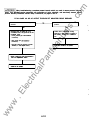
FLOW CHART 4-4. EXCITER FIELD BREAKER TRIPS
No
Check
dodes in
bad.
rou
or
Check Voltage Regulat>r aquslments and
connections.
assembly. Replace if
Check generau stator leads for proper,
secure COI11ecliou. Rater m approprial9
an
Check exciter stab' winding. Replace if
and
bad.
tM
eleclricaJ schematic.
Check exciler rou wincing. Repla:e if bad.
Check generator Sla1Dr windngs. Repla:e if
ca
bad.
High-voltage, 1,900 to 15,000 volts,
present special hazards of severe personal lnjuty or
death. Even after genset shutdown, an electl1cal
shock hazard may still exist, caused by Induced
voltage within the generator. Service personnel must
be well-trained/qualified to worlc with distribution
voltages.
ar
Replace if bad.
A DANGER
lP
Check generat>r ro1Dr field windng.
I ACAUTION I
Do not replace Voltage Regulator
VR21 until external trouble has been corrected to
avoid possible damage to new regulstor board.
w
.E
lec
tri
Replace Voltage Regulalor VR21 .
ww
Check for any loose or broken wires
connections m VR21 assembly.
ua
ls
Does AC output voltage build up m 150% or 1-----"-----l
•
more of rated voltage before breaker trips?
4-8
.c
om
/ AWARNING I
Many troubleshooting procedures present hazards which can result In severe personal injuty or
death. Only qualified service personnel with knowledge of fuels, electricity, and machlnety hazards should
perfonn service procedures. Review Safety Precautions, on pages 11 and Ill.
FLOW CHART 4-5. UNBALANCED GENERATOR OUTPUT VOLTAGE
load
at
generatx' terminals. Is
Check each
No
not withit
load.
phase
for balanced anent If
10% of each other, reclslriluE
ua
ls
Remove
ou1pUt slil unbalanced?
Yes
Check for correct gromdng of genenmr
and load
.
No
gromded property?
tM
Yes
No
Is generatx' statx' windng continuous?
A DANGER
ca
tri
lec
.E
w
ww
as
necessary.
Replace stator assembly.
High-voltage, 1,900 to 15,000 wits,
present special hazards ot severe personal lnjuly or
death. Even after genset shutdown, an electtlcal
shock hazard may still exist, caused by Induced
voltage within the generator. Service personnel must
be well-trained/qualified to WOlfe with distribution
voltages.
lP
Check load for ground fa�Als and conect as
necessary.
ar
Yes
Correct
an
Ale getl9faD leads connected and
4-9
.c
om
I AWARNING I
Many troubleshooting procedures present hazards which can result In severe persona/ Injury or
death. Only qualified setVIce personnel with knowledge of fuels, electricity, and machinery hazards should
perfonn setVIce procedures. Review Safety Precautions, on pages II and Ill.
FLOW CHART 40. NO AC OUTPUT THROUGH SET MOUNTED CIRCUIT BREAKER
Is set-mounted ciraJit breaker at Tripped
position?
Is set-fTlOIM'ltad ciraJit breaker at OFF
position?
ua
ls
No
Y•
Y•
Detarmile cause � breaker tip. H not
immeciately known, s� generaa set and
investigale cause
Cirait owerload (per sil&-eslabishecl
procedures).
Confirm flat no 111Mltanance is being
perb1ned, or other pwpose for breaker at
OFF position, and flat set is avalable for
.
use.
taUt
AIMaw Teeing AC laad Cirail Blaakar in
TasfS tn1 ....... 18dion.
operating and available for use,
reset cira.it breaker t» ON posiion.
ww
w
.E
lec
tri
ca
Conac:t fault COidlioii ... I8Set ciR:UI
ballar lEt ON poeilian.
If set is
tM
Shunt tip (check for generaa set
stMdcwn, or ofler SVNII sowce).
ar
•
Short cira.it (per sile oslabished
proceclu)res .
lP
•
an
•
4-1 0
.c
om
Section 5. Component Tests
and
Adjustments
U1 will energize and de-energize K12 depencing on the
number of crari<s programmed, K1 2 N.C. contacts (1 0,7)
open and close to energize and de-energize K3, K3 N.O.
contacts (S,3) open and ck>se connecting and removing
B+ from TB1 -8.
GENERAL
ua
ls
This section contains test and adjustment information for
the GenSet control, generator, and engine COIT1JOnents.
Refer to the figures included with this information and also
the Wiring Diagrams section when instructed.
H the set fails to start after the pre-set number of cranks,
U1 pins 1 0, 1 1 , and 1 2 go high and trigger the drive
transistor U4 pins 6 and 1 1 which grounds K6 fault relay,
stopping the starting sequence by opening its N.C. con
tacts (9,8) de-energizing K3 and K2. U 1 pins 1 0, 1 1 , and
1 2 going high also triggers U4 pins 1 2 and S which
energizes overcrank lamp drive relay K9. K9 N.O. con
tacts (9, 1 3 and 4,8) ck>se putting a ground on TB2-6 for a
remote indication and also the DS1 8 lamp.
High-voltage, 1,900 to 15,000 volts,
present special hazards of severe personal injury or
death. Even after genset shutdown, an electrical
shock hazard may still exist, caused by Induced
voltage within the generator. Service personnel must
be well-trained/qualified to work with distribution
voltages.
tM
I A CAUTION I
an
A DANGER
H the set starts, voltage builds up on the DC (K1 4) and AC
(K1 0) start disconnect relays. K1 4 energizes at approxi
mately 1 4 VDC. K10 energizes at approximately 1 00
VAC. Regardless of which one energizes first, either relay
will break the ground path to starter relay K3, K3 de
energizes opening its N.O. contacts (S,3) removing B+
from TB1 -8. Both K1 0 and K14 must be energized to
operate the run lamp DS1 2. Bther relay will also inhibit the
overcrank timer U1 by making U1 pin 2 go high. This is
achieved by removing the ground path from U1 pin 2
through U3 pins 6-1 1 , N.C. K14 contacts (1 6,9) and N.C.
K1 0 contacts (3,S). A positive is then alk>wed through the
K3 coil, N.C. K6 contacts (3,7), N.C. K 1 2 contacts (10, 7),
U3 pins 6-1 1 to pin 2 on U1 or via RS, U3 pins 6-1 1 to U1
pin 2 if K6 fault relay has operated. By making pin 2 high
the timer is reset and put into a standby mode.
lP
ar
In-depth intonnatlon Is provided tor
some components such as the ECM's. Only qualffled
personnel with proper equipment should use this ln
fonnatlon to attempt repair of printed circuit board
assemblies. Contacting your distributor tor replace
ment pans is recommended.
ENGINE CONTROL MONITOR (ECM)
Sequence of Operation - Detector-7 ECM
ca
Refer to schematic diagram in Wiring Diagrams section
when reviewing this information.
•
•
tri
Starting is initiated by applying B+ or ground to P4-7
depending on the position of �nks W3 and W4.
Position A - Ground signal to run
Position B - B+ signal to run
Either K1 0 or K14 will initiate US - LOP/HET time delay
timer. This is achieved by removing the ground from U4
pin 3 and allowing a positive there. This triggers U4 pin 1 4
to ground US pi n 2 . After a 1 0 seco nd delay U5 pin 1 4
energizes K1 through U4 pins 1 a nd 1 6. K1 N.O. (1 ,8)
contacts (9, 1 4) ck>se, latching in fault circuits. K1 N.C.
contacts open to latch US into an inactive state during run,
made by removing B+ from pin S and grouncing it through
R8 and U2 pins 2 and 1 S. (K1 N.O. contacts (2,8) also
ck>se providing timing shutdown path to K6 fault relay.)
.E
lec
This energizes run relay 1<7, which closes its N.O. con
tacts (9, 1 4) connecting B+ to starter relay K3, switched B+
relay K2 fault circuits, overcrank/cycle crank timer U1 ,
and HET/LOP time delay timer U5 through N.C. fault relay
K8 (1 6,9). This also opens N.C. K7 (9, 1 6) , disconnecting
B+ to the reset circuit (K6).
K2 energizes, closing its N.O. contacts (S,3) connecting
B+ to tenninal TB1 -10 through fuse F2 and to P4-9
through fuse FS.
H a fault should ocrur a ground is placed on the following
plug points.
•
K3 energizes, closing its N.O. contacts (S,3) connecting
B+ to tenninal TB1 -8 through fuse F1 . K3 is controlled by
timer U1 through cycle crank relay K12. U1 can be
programmed to give 3 crank periods by combining diodes
across U1 pins 1 0, and 1 2; CR6 to pin 1 2 with CR8 to pin
1 0 3 cranks.
ww
w
•
•
•
•
P2-2, for Pre-Low Oil Pressure (PLOP)
P2-3, for Pre-High Engine Temperature (PHEl)
P2-4, for Low Oil Pressure (LOP)
P2-S, for High Ergne Temperature (HET)
P2-6 or termnal TB1-1 , for Overspeed (OS)
Pre-LOP and pre-HET only activate a warning lamp and
do not stop the set.
=
5-1
.c
om
K2 energizes, closing its N.O. contacts (5,3) connecting
B+ to terminal TB1 -1 0 through fuse F2 and to P4-9
through fuse F5.
LOP, HET, ard OS activate a lamp ard also shut down the
set.
Fault relay K6 is in series with the K1 3 (HET) , K15 (LOP),
K1 1 (OS), K4 (Fault 1 ) ard K5 (Fault 2) fault relays.
Therefore, when a grourd is placed on the respective plug
input it will cause both the K6 relay ard the associated
fault relay to energize. K6 N.C. contacts (9,8) open to de
energize K2 relay, stopping the set. K6 N.O. contacts
(1 1 , 1 0) close to energize K8 relay. K8 opens its N.C.
contacts (1 6,9) to remove B-t from the operational parts of
the circuit. The associated fault relay will bring up an
indicating lamp ard also connect a grourd to one of the
following terminals for a remote indication:
TB2-8, for HET
TB2-1 1 , for PLOP
TB2-7, for Overspeed
TB2- 1 0, for PHET
TB2-9, for LOP
TB2-6, for Overcrank
•
•
•
•
•
ua
ls
•
K3 energizes, closing its N.O. contacts (5,3) connecting
B+ to terminal TB1 -8 through fuse F1 . K3 is controlled by
timer U1 through cycle crank relay K1 2 through N.C. fault
relay K6 contacts (2,3). U1 is set to provide 3 cranking
periods through CR6 and era. The timing is set to 15
seconds on, and 1 5 seconds off through oscillator circuit
comprising C3, and resistors U3 (3,6), (15,2), and (1 6,1 ).
The total crank time is 75 seconds.
U1 will energize and de-energize K1 2 through U4 (7, 1 0).
K12 N.C. contacts ( 10 ,7) open arxl close to energize and
de-energize K3, K3 N.O. contacts (5,3) open ard close
connecting and removing B+ from TB1 -8.
H the set fails to start after the three cranks, U1 pins 1 0,
and 1 2 go high and trigger the drive transistor U4 pins 6
and 1 1 which grounds K6 fault relay, stopping the starting
Se<J.Jence by opening its N.C. contacts (9,8) de-energiz
ing K3 aoo K2. U1 pins 1 o, 1 1 , aoo 1 2 going high also
triggers U4 pins 1 2 and 5 which energizes overcrank lamp
drive relay K9. K9 N .O. contacts (9,13 and 4,8) close
putting a ground on TB2-6 for a remote indication and a
reound on P3-8 to light the DS18 lamp.
•
•
•
•
tM
•
•
an
To reset a fault the run signal must be removed from P47 to de-energize K7, closing its N.C. contacts (9, 1 6) to
connect B-t to the fault reset circuit. A grourd is placed on
P4-1 1 which grounds all of the latchable fault relays reset
coils as follows:
K6 - Fault Relay
K15 - LOP
K9 - Overcrank
K17 - PHET
K19 - PLOP
K1 1 - Overspeed
K13 - HET
•
H the set starts, voltage builds up on the DC (K14) and AC
(K1 0) start disconnect relays. K14 energizes at approxi
mately 1 4 VDC. K10 energizes at approximately 1 00
VAC. Regardless of which one energizes first, either relay
will break the ground path to starter relay K3, K3 de
energizes opening its N.O. contacts (5,3) removing B+
from TB1-8. Both K1 0 ard K14 must be energized to
operate the run lamp DS1 2. Either relay will also inhibit the
overcrank timer U1 by making U1 pin 2 go high. This is
achieved by removing the ground path from U1 pin 2
through U3 pins 6-1 1 , N.C. K14 contacts (1 6,9) and N.C.
K1 0 contacts (3,5) . A positive is then allowed through the
K3 coil, N.C. K6 contacts (3,7), N.C. K1 2 contacts (1 0, 7),
U3 pins 6-1 1 to pin 2 on U1 or via R6, U3 pins 6-1 1 to U1
pin 2 if K6 fault relay has operated. By making pin 2 high
the timer is reset and put into a standby mode.
ar
This resets K6 fault relay and any fault relays that are
latched in an active state.
ca
lP
To stop the set normally, the run signal is removed from
P4-7 which de-energizes K7. K7 N.O. contacts (9,14)
open to remove B-t from K2 relay. K2 de-energizes
opening its N.O. contacts (5,3) removing B+ from TB1 - 1 0,
stopping the set.
Sequence of Operation - Detector-12 ECM
tri
Refer to schematic diagram in Wiring Diagrams section
when reviewing this information.
•
•
lec
Starting is initiated by applying B-t or grourd to P4-7
deperding on the position of �nks W3 ard W4.
Either K 1 0 or K14 will initiate U5 - LOP/HET time delay
timer. This is achieved by removing the grourd from U4
pin 3 and allow a positive there. This triggers U4 pin 1 4 to
ground U5 pin 2. After a 1 0 second delay U5 pin 14
energizes K1 through U4 pins 1 and 1 6. K1 N.O. contacts
(9,1 5) close, connecting B-t to the fault circuits. K1 N.C.
(1 ,8) contacts open to latch U5 into an inactive state
during run, made by removing B+ from pin 5 and ground
ing it through R8 and U2 pins 2 and 1 5. (K1 N.O. contacts
(2,8) also close providing tirring shutdown path to K6 fault
relay from appropriate fault circuit.)
Position A - Grourd signal to run
Position B - B+ signal to run
ww
w
.E
This energizes run relay K7, which closes its N.O. con
tacts (9, 1 4) connecting B+ to starter relay K3, switched B+
relay K2 fault circuits, overcrank/cycle crank timer U1 ,
and HET/LOP time delay timer U5 through N.C. fault relay
K8 (1 6,9). This also opens N.C. K7 (9, 1 6), disconnecting
B+ to the reset circuit (K6).
5-2
Checking Relay Coil
•
Connect B+ across relay coil terminals. Relay should
activate if coil is okay.
•
•
Checking Relay Contacts
•
•
Connect B+ to one side of relay contacts. Connect a volt
meter to other side of relay contact. If B+ i s present when
relay is energized, contact is okay. The B+ reading is
present in reverse order when checking normally closed
(N.C.) contacts. Typical wiring diagram is shown in Figure
5-1 .
•
•
ua
ls
•
•
•
Low fuel, pre-LOP, pre-HET, and LET only activate a
warning lamp and do not stop the set.
•
•
•
•
•
•
lP
•
•
ar
tM
an
LOP, H ET, OS, Fault 1 , Fault 2 and Remote shutdown
(TB2-1 6) activate a lamp and also shuts down the set.
Fault relay K6 is separately in series with the K 1 3 (HET) ,
K 1 5 (LOP) , K1 1 (OS). K4 (Fault 2) and K5 ( Fault 1 ) fault
relays. Therefore, when a ground is placed on the respec
tive plug input it will cause both the K6 relay and the
associated fault relay to energize. K6 N.C. contacts (9,8)
open to de-energize K2 relay, stopping the set. K6 N.O.
contacts ( 1 1 ,1 0) close to energize K8 relay. K8 opens its
N.C. contacts ( 1 6,9) to remove B+ from the operational
parts of the circuit. The associated fault relay will bring up
an indicating lamp and also connect a ground to one of the
following terminals for a remote indication:
TB2-8, for HET
TB2-2, for Fault 2
TB2-9, for LOP
TB2-4, for Fault 1
TB2-1 0, for PHET
TB2-6, for Overcrank
TB2-1 1 , for PLOP
TB2-7, for Overspeed
.c
om
RU N RELAY (IF EQUIPPED)
If a fault should occur a ground is placed on the following
plug points:
P2-1 , for Low Engine Temperature (LET)
P2-2, for Pre-Low Oil Pressure (PLOP)
P2-3, for Pre-High Engine Temperature (PHET)
P2-4, for Low Oil Pressure (LOP)
P2-5, for High Engine Temperature (HET)
P2-6 or terminal TB1 -1 , for Overspeed (OS)
TB2-1 4, for Low Fuel
TB2-1 , for Fault 2
TB2-3, for Fault 1
TB2-1 6, for shutdown of customers requirements
ca
To reset a fault the run signal must be removed from P47 to de-energize K7, closing its N.C. contacts (9, 1 6) to
connect B+ to the fault reset circuit. A ground is placed on
P4-1 1 which grounds all of the latch able fault relays reset
coils as follows:
K6 - Fault Relay
K 1 3 - HET
K - Fault 2
K 1 5 - LOP
K5 - Fault 1
K 1 7 - PHET
K 1 9 - PLOP
K9 - Overcrank
K 1 1 - Overspeed
•
A -�1--�
tri
•
OUTPUT
•
4
•
•
•
INPUT
•
lec
•
•
This resets K6 fault relay and any fault relays that are
latched in an active state.
s --1-----l
.E
To stop the set normally, the run signal is removed from
P4-7 which de-energizes K7. K7 N.O. contacts
open to remove
from K2 relay. K2 de-energizes
opening its N.O. contacts (5,3) removing
from
stopping
B+
B+
FIGURE 5-1. RUN RELAY
ww
w
the set.
(9,14)
TB1-1 0,
5-3
.c
om
INTERFACE RELAY MODULES
(IF EQUIPPED)
2
3
5
4
7
6
8
I
TB2
(INPUT)
TB1
(OUTPUT)
2
3
2
an
-1 '
ua
ls
When the customer provides a remote control panel
having alarm circuits powered by a separate AC or DC
source, Module A1 3 (7 relays) and Module A14 (5 relays)
can be provided to interface with the ECM (A1 1 ) circuits.
Typical wiring diagrams are shown in Figure 5-2.
4
5
3
K1
K5
K4
K3
K2
.
2
4
3
7
6
5
8
9
12
11
10
tM
1
4
13
14
I
ar
I
6
7
K7
K6
TB1
8
9
5
10
11
6
12
13
7
14
8
B+
ca
lP
A13
-I
I
1
2
181
ww
K3
K2
w
I
(INPUT)
tri
.E
lec
K1
TB2
3
4
5
6
7
K4
2
3
2
4
5
K5
3
6
7
4
8
9
10
TB1
(OUTPUT)
I
A14
FIGURE 5-2. INTERFACE RELAY MODULES
5-4
8
9
5
10
6
B+
ES-1854
.c
om
TIME DELAYED START/STOP MODULE
(IF EQUIPPED)
AC METERS AN D
CURRENT TRANSFORMERS
If a meter malfunctions, the problem might be a loose
wiring connection, the meter itseH, the phase selector
switch, or the current transformer for that meter. If more
than one meter is malfunctioning, you may have to check
for proper and secure generator tap connections. Check
appropriate AC wiring diagram/schematic for wire lead
and terminal connections. Checking continuity of the
wiring and components should identify the problem.
Repair or replace any faulty wiring, replace faulty meter,
current transformer, switch, etc. Refer to appropriate
wiring diagram/schematic in Wiring Diagram section.
an
tM
lWE DELAY STOP POTENTIOMETER
ca
lP
ar
TIME DELAY START POTENTIOMETER
ua
ls
This module contains adjustable potentiometers for time
delayed start (1 to 1 5 seconds) , and time delayed stop ( 1
to 1 5 minutes). Time delay adjustment i s made by turning
the appropriate potentiometer clockwise to increase or
counterclockwise to decrease the time delay. Set the time
delay start per site requirements, and the time delay stop
for approximately 3 to 5 minutes. Typical wiring diagram
is shown in Figure 5-3. Refer to Wiring Diagrams section
for further information.
tri
TB1
2
3
4
5
6
.E
lec
PRIMARY START-DISCONNECT (A1 1 - TB1 -2)
SECONDARY START-DISCONNECT (A1 1 - TB1-3)
B- (A1 1 - TB1-5)
B+ (A1 1 - TB1-7)
RUN SIGNAL OUT (A1 1 - TB1-6)
RUN SIGNAL. IN (REMOTE START/STOP CONTROL)
ww
w
FIGURE 5-3. TIME DELAYED START/STOP MODULE
5-5
ES-1855
.c
om
AUTOMATIC VOLTAG E REG ULATOR
Quadrature Droop Circuit (Optional): Converts the cur
rent input from a CT into a voltage which is phase mixed
with sensing voltage. The result is a net increase in the
outp� t from the sensing network as the power factor lags,
causmg a reduction in excitation.
The automatic voltage regulator (AVA) is a three-phase
full wave poweroutput type device, which forms part of the
excitation system for the generator.
I� a�diti�n to regulating the generator voltage, the AVA
c1rcu1try Includes a number of protective features which
provide safe reliable control of the generator. Excitation
power is derived from a permanent magnet generator
(PMG), providing low Radio Frequency Interference (RFI)
and immunity from thyristor type loads.
RMS Convener: Is a square law precision rectifier circuit
!hat converts the AC signals from the sensing networks
ua
ls
1nto a composite DC signal representing the mean
squared value of the waveform.
The output of the RMS converter includes a variable
potential divider which forms the voltage range control for
the AVA.
Th� AVR is interlinked with the main stator windings,
_
exc1ter f1eld
and PMG to provide closed loop control of the
output voltage with load regulation at approximately
±0.5% RMS.
Current Convener: Is a three-phase precision rectifier
and amplifier that converts the inputs from current trans
formers into a DC signal representing the mean value of
the current waveform.
an
The AVA senses the output voltage from the main stator
windings and in response to this controls the power fed to
the ex�iter field, a�d the main field, in such a way as to
_
mamta1n
the machme output voltage within the specified
limits, compensating for load, speed , temperature and
power factor of the generator.
tM
Offset Control: Provides an interface between the AVA
and accessories and allows the generator's excitation to
be controlled by adding or subtracting the accessory DC
output voltage to the AVA rectified sensing voltage.
Soft start circuitry is included to provide a smooth con
trolled build up of generator output voltage.
ar
Power Supply: Components consist of zener diodes,
dropper resistors and smoothing to provide the required
voltages for the integrated circuits.
Sust�ined overvoltage situations caused by open drcuit
sen�mg terminals or short circuit power device are
�vo1ded by overvoltage detection circuitry which provides
mternal shutdown and circuit breaker trip signals for
circuit i �lation if required.
lP
Precision Voltage Reference: Is a highly stable tem
perature compensated zener diode used for DC compari
son.
tri
ca
A frequency measuring circuit continually monitors the
shaft speed of the generator and provides underspeed
protection of the excitation system by reducing the gen
erator output voltage proportionally with speed below a
P!eset value. A further enhancement of this feature pro
VIdes greater voltage roll off in response to rate of falling
speed (dHz/dt) , to improve frequency recovery time on
turbocharged engines.
Current 6miting circuitry (optional) provides control over
the amount of short circuit current flowing during three
phase and single-phase shorts on the generator output.
Main Comparator/Amplifier: Compares the conditioned
sens��g voltages with the precision reference voltage and
_
amphf1es the dtfference
(error) to provide a controlling
sig �al fo� the power �evice in such a way as to supply the
exc1ter w1th the requ1red amount of power to maintain the
generator voltage within the spedfied limits.
lec
Stability Circuit: Provides adjustable negative AC feed
back to prevent voltage hunting and ensure good steady
state and transient performance of the control system.
Over excitation situations left uncontrolled are limited to a
sat� durat�on by i �ternal shutdown of the AVA output
.
dev1ce. ThiS cond1t1on remains latched until the generator
has been stopped.
.E
Power Control Driver: Provides the means to infinitely
control the conduction period of the output device. This is
achieved by pedestal and ramp control followed by a level
detector and driver stage.
Basic Operation
Power Control Devices and Rectifier: Are configured
as a three phase 4 diode bridge, power mosfet and
freewheel diode to vary the amount of exciter field current
in response to the error signals produced by the main
comparator.
w
The internal block diagram of the AVA board is shown in
Figure 5-4. The main functions of the AVA are as follows.
Sensing Resistors: Take a portion of the generator
output voltage and attenuate it to a suitable lower level.
This input chain of resistors includes the hand trimmer
adjustment.
ww
Soft Stan C!rcuitry: Overrides the precision voltage
reference dunng run up to provide a linear rising voltage.
5-6
.c
om
Sync: Circuit provides a short pulse near the zero point of
one of the phases on the PMG and is used to synchronize
the Under Frequency Roll-Off (U FRO) and power control
circuits to the generator cycle period.
Over Voltage Monitor: Continuously monitors the volt
age at the generator terminals and provides signals to
shut down the output device and trip an optional circuit
breaker, to i solate power from the exciter and AVR in
event of sustained overvoltages. A one second timer is
included i n the circuitto prevent operation during transient
overvoltages, which are normal after load removal.
Under Frequency Roll-Off: Circuit measures the period
of each electrical cycle and causes the reference voltage
to be reduced approximately linear with speed below a
presettable threshold. A light emitting diode (LED) gives
indication of underspeed running.
ua
ls
Overload Detector: Continuously monitors the level of
excitation and provides signals to shut down the output
device in event of sustained overloads lasting greater
than ten seconds. Both the overload and overvoltage
conditions are latched faults requiring the generator to be
stopped for reset.
tM
an
Block Relief: Circuit measures the rate of falling speed of
the generator (dHz/dt) and causes greater voltage roll off
(makes the V/Hz slope steeper) to aid engine speed
recovery after application of a "block" load.
UFRO
+ BlOCK
REUEF
OVER
,..
VOLTAGE
.....
DETECTOR -
ar
OVER
VOLTAGE
MONITOR
::.
CONTROL
tri
,..
SENSING
RESISTORS
��
'<�
RMS
CONVERTER
lec
GENERATOR
VOLTAGE
....
SENSING
OFFSET
REMOTE .....
.E
VOLTAGE
TRIMMER
"'-
POWER
SOFT
,...__
-
BREAKER
DRIVE
+ INHIBIT
I
PRECISION
'--
POWER
VOLTAGE
SUPPUES
REFERENCE
�
ww
_..
EXCITATION
ClRCUIT
BREAKER
(OPTIONAL)
r---4
R
.....__ _
rr-
.... �
SYNC
v
STABIUTY
CIRCUIT
POWER
CONTROL
DRIVER
-
POWER
CONTROL
DEVICES
OVERLOAD
DETECTOR
+ INHIBIT
,--
�
I>I>-
CURRENT
CONVERTER
1
w
CURRENT ,..
INPUT ,..
QUAD
DROOP
-
"""
RECTIFIER
START
CIRCUIT
lP
ca
ACCESSORY ,..
INPUT
r-o-
100 HZ PMG
FIGURE 5-4. PMG VOLTAGE REGULATOR BLOCK DIAGRAM
5-7
EXCITER
FIELD
.c
om
G EN ERATO R O PERATI ON REVI EW
Two, similar PMG voltage regulators have been used In per
manent magnet exciter generator sets. One Is a four
position mount, and the newer of the two has six mounting
holes (of which only four are used). Adjustment proce
dures are the same for both, even though the potentlone
ters are located differently. Refer to Figure 5-6 to Identify
which PMG AVR the unit is equipped.
The PMG provides power via the AVA to the main exciter
stator, see Figure 5-5. Excitation power is therefore inde
pe �dent of output voltage , resulting in positive voltage
_
build-up, w1thout
reliance on residual magnetism. The
AVA compares the main stator output with a reference
value and feeds a controlled excitation current to the main
exciter stator. The AC output of the main exciter rotor is
c? n �erted to DC by the rectifier assembly, comprised of
s1x d1 �des mounted on two heatsinks to form positive and
negat1ve plates. The diodes are protected against harmful
overvoltges (caused for example, by switching circuits or
out-of-phase paralleling) by a metal-oxide varistor
(MOV). Th e DC output of the rectifier assembly provides
_ _ onto the main rotor.
the exc1tat1on
ua
ls
The generator voltage may be adjusted within ±3 percent
of the rated nameplate voltage via the optional control
pa�el mounted voltage control rheostat ( A21 ). If the
adjustment cannot be made with A21 , or if A21 is not in
stalled, adjust the voltage regulator as follows:
1 . Adjust voltage control rheostat A21 (if available) to
the mid position.
Loosen the locking nut. With a screwdriver, turn
rheostat A21 fully counterclockwise, then fully
clockwise, then to mid position.
•
an
AVR Sensing and Power Supply
3-Phase Sensing: With rated output voltage on the main
terminals, the reference supply to this unit should be
between 1 70 and 250 volts AC across 6-7, 7-8 and 8-6.
This supply can be by way of a quadrature droop burden
resistor and/or dropper transformer. These should be
checked for continuity.
tM
2. Open the control panel doors to gain access to the
voltage regulator.
3. With the generator set operati ng, and the voltage
being monitored (either by meters on the set or with
remote metering) , adjust voltage regulator board
Volts potentiometer to the desired generator voltage.
ar
Power Supply (PMG): Power supply is derived from the
permanent magnet exciter. Its output leads are connected
at AVA terminals P2, P3 and P4. These must first be dis
connected. With the machine at rated speed the output
voltage between leads P2-P3, P3-P4, and P4-P2 should
be balanced at approximately 1 65 volts for 50 Hz (1 500
rpm) units or 200 volts for 60 Hz ( 1 800 rpm) units.
lP
5. Stor:> and restart generator set to confirm proper op
eratiOn.
ca
Voltage Regulator Adjustment
4. :e �orm fine voltage adjustment (±3 percent) by ad
JUSting rheostat A21 , retighten locking nut.
.E
lec
tri
Generator voltage is controlled by the optional voltage
control rheostat (A21 ) located on the control front panel
and the solid-state voltage regulator located inside control
panel (see Figure 5-6) .
PERMANENT
MAGNET
STATOR
AUTOMATIC
VOLTAGE
REGULATOR
OUTPUT
MAIN
STATOR
EXCITER
STATOR
IJm ----t---r-
w
ww
6. If adjusting the Volts potentiometer of the voltage
regulator ��rd do� s not allow the generator voltage
�o come Wl! htn d�s1red range, refer to wiring diagram
Included w1th untt and check for proper connections.
Repe�t t�e adjustment procedure. If proper adjust
_
ment 1s still not possible,
review the following regard-
MAGNET
ROTOR
---t-1 Jn
1 -t---
---+EXCITOR
ROTOR
sHAFT
----...1 ----IL�
TING
DIODES
MAIN
ROTOR
FIGURE 5-5. PERMANENT MAGNET GENERATOR (PMG) EXCITATION SYSTEM (BLOCK DIAGRAMS)
5-8
ES-1852
.c
om
DIP (Voltage Dip Limit): This control is preset at ap
proximately 30 percent of the operating voltage.
Turning the control clockwise increases the voltage
dip on large load pickup. This will make it easier for the
engine to pick up load. Turning the control counter
clockwise reduces the voltage dip (makes the AVR
"stiffer"). The engine may not be able to pick up the
load if the Voltage Dip Limit is set too far counterclock
wise.
ing other potentiometers on the AVR (note that a non
PMG regulator does not have all the same potenti
ometers as a PMG regulator). Replace voltage regu
lator board, or contact your service representative for
assistance.
I A CAUTION )
ua
ls
Sealed voltage regulator poten
tiometers are factory-calibrated for operation
with this generator set. Any adjustment of other
components could cause generator set voltage
instability or overheating. Further adjustments
should only be made by a qualified service repre
sentative.
Droop: To set generator droop to 5% at full load, 0
PF. Turning this control clockwise increases the
droop (the VUmt may also need to be adjusted if there
is too much droop )
.
Stability: If the voltage is unstable after a block load
reduction, tum the Stability control clockwise. Opti
mum setting should be found around mdpoint. Any
stability adjustment affects the generator output volt
age. Reset the output voltage after any stability ad
justment.
an
Trim: To match AVR input to accessory output.
Turning this control clockwise allows accessories,
like a VARIPF controller, more control over the AVR.
OverN: To set the overvoltage protection cutoff level.
Turning this control clockwise increases the overvolt
age cutoff level.
tM
Under Frequency Roll Off (UFRO) Knee Point:
This control is set at 58 to 59 Hz (60 Hz units) or 48
to 49 Hz (50 Hz units). The LED (light emtting diode)
adjacent the UFRO potentiometer will be lit when the
voltage regulator is in the under frequency mode, off
is the standard operating mode. To check, reduce
generator frequency from rated to where the LED just
begins to illuminate. Note set point frequency. Turn
ing the UFRO potentiometer clockwise reduces the
knee point fre<JJency, and the LED will extinguish.
Return set to rated frequency.
ar
ULimit: To set the maximum short drcuit current.
Turning this control clockwise increases the short
drcuit current.
lP
FREQUENCY SELECnON LINKING:
1
2, 60Hz, 6-pole
2 - 3, 50Hz, 4-pole
1 - 3, 60Hz, 4-pole
No lilk, 50Hz, 6-pole
-
[Q]
0
DROCP (!]
VITRN
TRIM
.E
lec
§
§
STABLITY
[!]
§�
w
ww
PERMANENT MAGNET GENERATOR (PMG) AVR
(AFTER JAN. 1, 1990)
STABILITY
tri
DIP
ca
PERMANENT MAGNET GENERATOR (PMG) AVR
(PRIOR 10 JAN. 1, 1990)
Stab/1, EXC, and RMS: Are set at factory, and
should not require any adjustment. Replace AVR.
I
I
CPTMJM
RESPONSE
SELECTION
EXC (!]
[Q]
CNEPJII
RMS
(FACTORY
SET)
�
§
[!]
[QJ
OPTIMUM RESPONSE SELECTION UNKING:
ES-1856-1
RGURE 5-6. PMG VOLTAGE REGULATORS
5-9
A - B, FRAMES 6 & 7
B - C, FRAMES 3, 4 & 5
A - C, FRAMES 1 & 2
A
B
c
.c
om
OVE�U N DER VOLTAG E SENSOR
MODULE (IF EQUIPPED)
A1 1 - TB2-1
Rotate the appropriate arrow i ndicator to adjust the
module , the recommended approximate settings are:
90
5
Over % Volts Set
% Volts Reset
1 10
5
0
14
18
0
The module includes an adjustable time delay relay to
prevent nuisance tripping (typically set at 25 percent, or
approximately 2.5 seconds). See typicalwiring diagram in
Figure 5-7.
0
16
0
L
N
21
26
25
0
0
0
A1 1 - TB2-3
A1 1 - TBH O
A
T.D.
�:
B
FIGURE 5-7. OVER/UNDER VOLTAGE SENSOR MODULE
lec
CRANKING
POTENTIOMETER
@]
0
0
OVE�UN DER FREQUENCY SENSOR
MODULE (IF EQUIPPED)
.E
Rotate the appropriate arrow indicator to adjust the
module , the recommended settings are:
w
Under Hz Set
Reset
ww
Over Hz Set
Reset
50
45
47
55
53
28
0
ES-1858
The Overspeed potentiometer is adjustable from 1 500 to
2500 RPM. Adjust the Overspeed potentiometer to
achieve overspeed at approximately 1 800 to 1 900 RPM
for 50 Hz units and 2100 to 2200 RPM for 60 Hz units. See
typical wiring diagram in Figure 5-9.
tri
ES-1857
Nominal Hz
25
0
This module derives a speed (Hz) signal from the PMG
but is powered from the generator set battery. A small time
delay, typically one second, is incorporated in the over
speed function to allow for engine overshoot. The module
contains two adjustable potentiometers, Overspeed and
Cranking (the cranking potentiometer is not used how
ever).
ca
93
GND
26
0
lP
9
1
N
OVERSPEED (FREQUENCY DETECTION)
MODULE
A1 7
TB21-26
K17
L
FIGURE 5-8. OVER/UNDER FREQUENCY SENSOR MODULE
24
28
16
0
an
22
A18
tM
0
15
12
24
ar
18
11
21
12
TB21-26
GND
0
14
15
0
11
ua
ls
Unde r % Volts Set
% Volts Reset
DO
60
10 (P3)
0
@]oD D
55
57
65
63
See typical wiring diagram in Figure 5-8.
OVERS PEED
POTENTIOMETE R
1--+-+- 9 (P2)
1---lr+- B-
}- TERMINAL
AUXILIARY
BLOCK
1--+-+r- B+ (A1 1 - TBHO)
1--i<-+- SIGNAL OUT (A1 1 - TB1-5)
1--+-+- NOT USED
�1-+-- B+ OR B- (A1 1 - TB1 -1)
1--1-+- NOT USED
ES-1858
FIGURE 5·9. OVERSPEED (FREQUENCY DETECTION) MODULE
5-1 0
The rectifier assembly, Rgure 5-1 0, is split into two plates,
the positive and negative, and the main rotor is connected
acros� these plates. Each plate carries 3 diodes, the
negat1ve plate carrying negative based diodes, and the
positive plate carries positive based diodes. The correct
polarity diodes must be fitted to their respective plate.
.c
om
ROTATING RECTIFIER ASSEMBLY
4.
Reverse ohmmeter leads from Steps 2 and 3 and
record resistance value of each rectifier; positive
stud (X) to CR1 , CR2, and CR3; and negative stud
(XX) to CR4, CR5, and CR6.
5.
All the resistance readings should be high in one test
and low in the other test. If any reading is high or low
in both tests, rectifier assembly is defective.
�eplace defective rectifier assembly with new, iden
tical part.
ua
ls
6.
I A CAUTION I
s e dust or din on di
Excesiv
odes and other components will cause over
heating and eventual failure. Keep these assem
blies clean!
an
Use 24 Jn.lbs. (2.7 N•m) torque when replacing nuts of positive (X)
and negative (XX) studs, and CR1 to CR6.
tM
Replacing Rectifiers
To replace rectifiers use the following procedure:
1 . Disconnect diode lead wire from stud terminal.
ar
2. Use proper size wrench to unscrew dode from
rectifier assembly base.
lP
3. AWIY heatsink COI1lJOUnd to underside of new ci
ode. DO NOT apply this COI1lJOUnd to clode stud
threads.
FIGURE 5-10. TES11NG ROTA11NG RECllAER ASSEMBLY
ca
Surge Suppressor
lec
tri
The surge suppressor (varistor) connected across the two
rectifier plates prevents high transient reverse voltages in
the field winding from damaging the diodes. This device
i � no� polarized and will show an infinite reading in both
_ an ohmmeter. H defective, signs of burning
d1�ect1ons with
w111 probably be apparent and it will give a full deflection
(short-circuit) reading. Replace if defective.
Rectifier Diodes
':Jsing
.E
an accurate ohmmeter, test each CR using nega
tive and positive polarities. Test rectifiers (diodes) as
follows:
1.
Disconnect all leads from assembly to be tested.
Connect one lead to the positive (X) stud and
connect other lead to CR1 , CR2, and CR3 in tum;
record resistance value of each rectifier.
w
2.
Connect one lead to the negative (XX) stud and
connect other lead to CR4, CR5, and CR6 in tum·'
record resistance value of each rectifier.
ww
3.
4. Insert new diode into mounting hole. Torque cfJOdes
on rotating rectifier assembly to 36-42 in-1:>5. (4-4.8
N•m).
5. Reconnect diode lead wire to stud teminal. Use 24
in-lbs. (2.7 N•m) torque when repladng nuts.
PERMANENT MAGNET EXCITER
The permanent magnet exciter is the main power supply
for a PMG A VR and is isolated from all other windings.
For this reason the output from the exciter must be tested
independently across its terminals, which are connected
to auxiliary terminal board (exciter leads P2, P3, and P4).
With the machine run up to full speed, the output voltage
across the leads P2, P3, and P4 should be balanced at
approximately 1 65 volts for 1 500 rpm (50 Hz) or 200 volts
for 1 800 rpm (60 Hz) between terminals. The permanent
magnet exciter will produce an output voltage completely
independent from the rest of the machine, and has no
effect on the separate excitation tests that follow. Refer
to appropriate wiring diagram/schematic in Section 7.
The permanent magnet excHer stator resistance Is 4.4 ohms line
to-line.
5-1 1
.c
om
EXCITER ROTOR
Testing for Grounds
EXCITER STATOR
Testing for Grounds
Connect leads of ohmmeter between each CR lead and
exciter rotor laminations. Use an ohmmeter set at the
highest resistance range. An ohmmeter reading less than
one megohm ( 1 ,000,000 ohms) indicates defective
ground insulation. See Figure 5-1 1 .
Using an ohmmeter, R x 1 00 scale, measure the insula
tion resistance between either lead X or XX and the lam
nations, Rgure 5-1 2. A reading of less than infinity indi
cates a ground.
ua
ls
Testing for Open or Shorted Windings
Use a Wheatstone Bridge for this test. Disconnect main
rotor field leads which oonnect to rotating rectifier assem
blies at the positive and negative studs. Disconnect lead
wires from diodes CR1 , CR2, CR3, CR4, CR5, and CR6.
Test between exciter lead pairs U6-V6, V6-W6 and U6W6. Refer to Table 5-1 for resistance values.
an
Be sure to Identify the gensel model, kW rating and generator
frame size from the generator set nameplate before reviewing
Table 5-1.
tM
FIGURE 5-12. TESllNG EXaTER STATOR FOR GROUNDS
Testing Winding Resistance
ar
Measure ooil resistance between leads X and XX with an
ohmmeter, scale R x 1 . See Rgure 5-1 3. Refer to Table
5-1 for resistance values.
lec
CR5
.E
SCHEMATIC
OF EXCITER
WIRING
CAL'
G-1183-2
FIGURE 5-13. TES11NG EXaTER STATOR FOR OPEN aRCUIT
CR5
G-1183-1
GENERATOR ROTOR
Testing for Grounds
FIGURE 5-11. TESTING EXaTER ROTOR
Use an ohmmeter, (R x 1 00 scale) and measure as
follows:
w
ww
OHMMETER
tri
ca
lP
Be sure to Identify the genaet model, kW rating and generator
frame size from the generator set nameplate before reviewing
Table 5-1.
1 . Disconnect rotor leads from the rotating diodes.
2. Measure between either lead and the rotor shaft,
FigUre 5-14.
3. A reading of less than infinity indicates a ground.
5-1 2
.c
om
Connect all (U, V, and W) stator output leads together.
Use an ohmmeter set on the R x 1 00 scale and measure
the insulation resistance between these windings and the
stator frame. A reading of less than infinity indicates a
ground. Field circuit breaker can be either open or closed
for this test.
Testing for Shorts
G-1187
FIGURE 5-14. TESllNG GENERATOR ROTOR FOR GROUNDS
ua
ls
CONTACT ONE PROD TO EACH OF 1HE FIELD LEADS
AND OTHER POOD TO ROTOR SHAFT.
F ROTOR IS GOOD, lHERE WU BE
ONE MEGOI-N OR GREATER RESISTANCE.
To check for shorts between individual windings, first refer
to electrical schematic to determine individual coil lead
wires (U5-U6, U1 -U2, etc.). Be sure to disconnect the in
strumentation leads and stator leads U1 , U2, US, V2, and
W2. Connect an ohmmeter, R x 1 00 scale to one lead of
a stator winding (leaving the other end of coil winding
being tested open), and the other ohmmeter lead to all
other stator leads connected together.
Example:
Ohmmeter lead to: U6 coil winding lead.
Ohmmeter lead to: U1 , 2, V1 , 2, 5, 6, W1 , 2, 5, and 6
connected together.
Coil winding lead US, open.
Testing for an Open Circuit
an
•
1 . Disconnect and test between rotor leads, F�gure 51 5.
•
•
2. Replace the rotor if it is grounded or has an open or
short. Refer to Table 5-1 for resistance values.
tM
A reading of less than infinity indicates a short. Repeat
test for all six coils.
Measure resistance of windings using a Kelvin Bridge
meter. Refer to Figure 5-1 6. H any windings are shorted,
open, or grounded, first check the leads for broken wires
or damaged insulation. H winding leads show no damage,
and it is determined that windings are damaged internally,
replace the stator assembly. Refer to Table 5-1 for resis
tance values.
ar
Be .ure to Identify the gensel model, kW rating and generator
frame size from the generator aet nameplate before reviewing
Table 5-1.
ca
lP
OHMMETER
G-1187-1
TEST BEJW:EN WIRE PAIRS
UIH.O, V6-LO, W&-LO
tri
ca.ITACT ON: PROO TO EACH
FELD LEAD
Be a�re to Identify the gensel model, kW rating and genwator
rr.ne size from the generator aet nameplate before reviewing
Table 5-1.
FIGURE 5-15. TES11NG
lec
GENERATOR ROTOR FOR
OPEN aRCtJT
.E
GENERATOR STATOR
A DANGER
ww
w
High-voltage, 1,900 to 15,000 volts,
present special hazards of severe personal Injury or
death. Even after genset shutdown, an electrical
shock hazard may still exist, caused by Induced
voltage within the generator. Setvlce personnel must
be well-trained/qualified to worlc with distribution
voltages.
THREE PHASE t.l)[)ELS,
TEST BETWEEN WIRE PAIRS
U1 -U2, V1 -V2, W1·W2,
lJ5.U6, V5-V6, W5-W6
Testing for Grounds
Before testing stator, disconnect all external load and
control wires. Isolate from ground and each other.
FIGURE 5-16. TES11NG GENERATOR STATOR WINDINGS
5-1 3
.c
om
TABLE 5-1 . WINDING RESISTANCE VALUES*
NTS
NT6
NTA2
NTA2
OFCC
OFEB
OFFA
OFEC
OFFB
NTA3
KTA1 2
KTT1 1
OFGA
OFGB
OFGC
1 75
1 75
1 75
200
200
200
4C
4C
4C
25
25
25
0.14
0.14
0. 1 4
0.01 7-0.023
0.01 7-0.023
0.01 7-0.023
0.91
0 .91
0.91
200
200
220
220
220
250
230
230
250
250
40
40
40
40
4E
4E
4E
4F
25
25
25
25
25
25
25
25
0.14
0.14
0.14
0. 1 4
0.14
0. 1 4
0.14
0.14
0.014-0.020
0.01 4-0.020
0.01 4-0.020
0.01 4-0.020
0.01 0-0.01 5
0.01 0-0.0 1 5
0.01 0-0.0 1 5
0.0097-0.01 0
1 .04
1 .04
1 .04
1 .04
1 .17
1 .1 7
1 .1 7
1 .35
sc
sc
25
25
25
25
25
0.1 7
0. 1 7
0. 1 7
0. 1 7
0. 1 7
0.068-0.0090
0. 0068-0.0090
0.0058-0.0080
0. 0058-0.0080
0.0043-0.0069
1 .55
1 .55
1 .77
1 .77
1 .96
275
300
275
350
400
450
450
500
VTA1
VTA2
VTA3
440
500
600
OFJA
OFJB
OFJC
OFJO
OFLA
OFLB
KTA31
KTA32
KTA33
620
660
800
900
900
OFLC
OFLO
OFMA
OFMB
KTA53
KTA54
KTT51
KTT52
SE
SF
6A
25
25
1 7""
0. 1 7
0. 1 7
0. 1 6
0.0043-0.0069
0.0031 -0.0042
0 .0037-0.0053
1 .96
2.16
1 .37
6B
6B
6C
6C
60
60
1 7""
1 7""
1 7""
1 7""
1 7""
1 7""
0. 1 6
0.1 6
0.16
0. 1 6
0. 1 6
0. 1 6
0.0030-0.0033
0.0030-0.0033
0.0023-0.0028
0.0023-0.0028
0.001 8-0.0023
0.001 8-0.0023
1 .47
1 .47
1 .66
1 .66
1 .89
1 .89
7B
7G
7G
7G
1 7""
1 7"*
1 7""
1 7**
0.20
0.20
0.20
0.20
0 .001 2-0.001 8
0.001 2-0.001 8
0.001 2-0.00 1 8
0.001 2-0.00 1 8
2 .29
2.29
2.29
2.29
ca
750
800
900
1 000
1 000
1 1 00
tri
KTA51
KTA52
550
50
50
SE
lP
31 0
330
400
400
450
KTT1 2
ROTOR
lec
1 1 20
1 200
1 1 00
1 280
1 250
1 250
1 500
ua
ls
NT4
NTS
STATOR
(Per Phase: Wye
or Series Wye)
an
OFAB
OFBO
OFBE
OFAC
OFBE
OFBF
OFCB
OFCB
NT4
NT4
EXCITER
STATOR ROTOR
ar
OFAA
OFBC
OFBO
GEN.
FRAME
SIZE
KW RATING
50Hz 60Hz
tM
GENSET
MODEL
DESIGNATIONS
.E
* Resistance figures are approximates, at 68°F (20°C) ±1 0%.
** Units built prior to November, 1989, were 28 ohms.
RECONN ECTION
ww
w
Rgure 5-1 7 shows the general reconnection possibilities for the generators. When reconnecting for a different voltage,
refer to AC Reconnect Wiring Diagram in Section 7 and AC diagrams that came with unit.
5-1 4
.c
om
GENERATOR CONNECTION
WIRING DIAGRAM
GENERATOR
CONNECTION
SCH EMATIC
DIAGRAM
1
60
� �-+--z
1 1 5/230 1
50 ---4---�-4
1 1 0/220
1
50
�
...J
w
c
w
ffi
U2
V6
:::>
WI
g
W2
Ul
�. P"'"
I i L2 (WJ
.�
•
WI
C')
1 20/240 3 60
c
z �-+------�--�� en
w
<
L
3
50
1 1 5/230
3
50
1 20/208
1 27/220
1 39/240
3
3
3
60
60
60
C\1
c
z
ww
H
6----'1
W2 W5
L2 (V)
50
50
50
N
•
V2 -r,..
V5 -V""
U2 -r,..
U5 -V""
T (WJ
�===:=!J.c:J.L3
w
V
U
�--
LO( N J
5 V2-:.
4
W5-
5
- W6 7
- VI
- V6
6
•
-
60
220/380
3
50
230/400
3
50
240/41 6
3
50
254/440
3
50
347/600
3
60
f-- W2
V r- W I 4
t-- V6
U I=-V I
L..3;r-U6 8
6
4
- UI
- U6
- WI 8
5
W2
��+--w r- w6 --HH--- 7
W5V2---...
V5-./"'
u2- '>a
U5-C
•'-"-'
�
U2
U6
V2
v
V6"
4
L2 ( V )
V5
Ul
W5
...J
CT22
- LO ( N )
�
W,_
I --
�
�
-=�\_�-N�- UV II
5"
5=
u::;:
5==
V5
W5 W f6
W2
7 ----..�
v
V2 ---t=w:===-+-
V
4
��� 6
r--- U I
u r-- u6
�r-- w 1 8
8
WI
W6
V6
l:ui22-=�-===u=-+- U6
W5-
,--
N
iri- V I
V5-l/
�r- u l
U5•
�
en
w
a:
w
en
W2
W5
CT23
4
'----��6bl-�- LJ ( W)
-
W26
v
�
6
V2----�7
u
U2- -i;:r-- U6
8
�r-- w 1 5
-+==+-El'-�I
W
::a
W57 V2- ::a
V5 -
4 8 U2 -
w
W2-��W6
�
.__
-WI
5-----+-=:=::IIEt- V I
-UI
W2 6--� W
•- w6
W5 -f't
v
7 V2 •- V6
V5 _IJI'
u
U2 •- u6
8
U5 -
-
..-t'----'W-'-'1�
--t-411-t--
60
60
60
7
�r-- U I
l1 -;r---
CT2 1
r;========:J..JI-+T_J__ L I ( U )
tri
3
3
3
3
V -W I
V2 - V6
W5 U:_,t- V I
...
8 -----t.��
I._
__.
U6
5
CT23
f
•
lec
220/380
240/41 6
254/440
277/480
w
�
3
3
3
.E
L
1 1 5/200
1 20/208
1 27/220
VI
V5
V2
L-----
C')
c �-+------;---r-�
...J
z
w
<
1 1 0/1 90 3 50 ...J
z
W6
a:
w
en
Ul CT22
lP
1 1 0/220
·�
W5
ca
z
U5
U2
�
'w
--,__- w6
�5 --1;-.+==::J:ii
U2-
ar
�
�
L
FT21
r;:::;::;=
T u cu J
6 ==::::Lji'*J-
...J
-
•CT21
�6)1---- LO (N)
ua
ls
1 20/240
t
�....,
FRAME S, 6, 7
FRAME 4
an
L
v
W5
I . L L l (U)
I
tM
C')
c
Vi
PHASE SEQUENCE U.V.W. WHEN
ROTATING CLOCKWISE VIEWED
AT THE DRIVE END
U5 __j-
•- w&
v
..I- V 6
U
•r-- u&
'--
W6
ES1866c
FIGURE 5-17. RECONNECTION DIAGRAM
5-1 5
I
a:
0
1<(
8
8
> >
"""
C\1
"""
C\1
C\1
....
+
C\1
....
5
5
0
-:.1::.
t>
a:
t>
i=
w
z
¢
t>
<(
n
w
...J
e
z
::l
a:
�. ffl�
z
0
:::E
:::E
0
t>
1�1�11@1�1�11�11�1�1�1�1@1
4
5
6
7
8
9
10
3.
Run Speed potentiometer.
A. Tum the screw counterclockwise 20 turns.
B. Tum the screw clockwise 1 0 turns.
C. This will set the run speed potentiometer to its mid
position.
4.
Gain potentiometer.
A. Set the Gain adjustment at the third division from
zero.
5.
Droop potentiometer.
A. For i sochronous operation, the droop potenti
ometer must be turned fully counterclockwise
and will not require any further adjustment.
B. Tum the screw to approximately 40 for 3 percent
droop.
C. Tum the screw to approximately 80 for 5 percent
droop.
11
IDLE S PEED
RUN SPEED
GAIN
DROOP
an
3
Idle Speed potentiometer.
A. Tum the screw counterclockwise 20 turns.
B. Tum the screw clockwise 1 0 tu rns.
C. This will set the idle speed potentiometer to its
mid position.
D
D
1f2
�
tM
2
@
�
Calibration Checks:
1 . Start the generator set.
lP
ca
Gain: The Gain control is a one-turn potentiometer. It is
used to adjust the sensitivity of the governor. A clockwise
rotation of the potentiometer will shorten the response
t:me to load changes.
With the generator set warmed up to proper operat
ing temperature, adjust the Run Speed potentiome
ter until the engine is operating at the desired
frequency or r/min.
tri
Droop: The Droop control is a one-turn potentiometer. It
is adjustable for zero % (isochronous) to more than 5%
speed droop. Fully counterclockwise rotation is 0% speed
droop.
3. With no load connected to the generator set, turn the
GAIN adjustment clockwise slowly until the actuator
lever oscillates. Reduce the GAIN adjustment
slowly counterclockwise until the lever is stable.
Upset the lever by hand. If the lever oscillates up to
3 deminishing oscillations and stops, the setting is
correct.
lec
Idle Speed: The Idle Speed control is a 20-turn po
tentiometer for adjusting the idle speed. A clockwise
rotation will increase the idle speed.
.E
Run Speed: The Run Speed control is a 20-turn po
tentiometer for setting t h e desired no-load governed
speed. A clockwise rotation will increase the run speed.
4.
Refer to the following adjustment procedures.
Adjustments
w
Preliminary A djustments:
1 . Frequency Adjust (engine speed) potentiometer on
control panel (if equipped) .
A. Loosen the locking nut.
B. With a screwdriver, turn th e potentiometer fully
counterclockwise , then fully clockwise , then to
mid position.
C. Hold mid position setting with screwdriver, and
tighten locking nut.
ww
For proper full-load generator set operation the
engine no-load speed must first be adjusted to the
desired allowable speed droop. ( For example : iso
chronous operation set to 60.0 Hz/1 800 r/min (50.0
Hz/1 500 r/min), for 3% speed droop set to 61 .8 Hz/
1 854 r/min (5 1 .5 Hz/1 545 r/min) , for 5% speed
droop set to 63.0 Hz/1890 r/min (52.5 Hz/1 575 r/
min.)
ar
2.
FIGURE 5·18. ELECTRONIC GOVERNOR
.c
om
Q.
::l
2.
ua
ls
ELECTRON IC G OVER NOR
Generator frequency is in direct ratio to engine speed
which is controlled by the governor. The governor control
has four potentiometers for making adjustments. See
Figure 5-18. Use a frequency meter or tachometer to
monitor the unit during adjustment procedure.
Apply and remove loads to check generator set re
sponse. If generator set operation is satisfactory,
the governor is now calibrated. If generator set
response is not satisfactory, review Step 3. If
electric governor cannot be properly calibrated,
contact your service representative for assistance.
Fine Speed Adjustment: After the GAIN adjustment is
made, the full load governed Run Speed may require a
minor adjustment to equal the desired speed (i. e . , 60 Hz,
1 800 r/min or 50 Hz, 1 500 r/min) . Use the SPEED AD
JUST potentiometer (when supplied) on th e engine in
strument panel for fine speed adjustments of less than
±1 00 r/min.
5-1 6
.c
om
Electric Fuel Control {EFC) Governor
System Description
FUEL
SHUTOFF
VALVE
ACTUATOR
STUDS
The EFC governor system contains a magnetic pickup,
electronic control, and the fuel pump actuator. See Rgure
5- 1 9.
MAGNETIC
PICKUP
SENSOR
ua
ls
FUEL PUMP
ACTUATOR
an
FUEL
FLOW
FIGURE 5-20. FUEL PUMP ASSEM BLY
ENGINE
FLYWHEEL
RING GEAR
AGURE 5-19. EFC GOVERNOR SYSTEM
Check that oonnections are clean and tight. A light coating
of non-conductive grease will help retard oorrosion at
terminals.
lP
The magnetic pickup senses engine speed at the flywheel
ring gear and sends an alternating current (AC) electrical
signal to the governor oontrol.
ca
The governor oontrol oompares the electrical signal from
the magnetic pickup with a preset reference point. H there
is a difference in the two signals, the oontrol will change
the current to the actuator (located on the ergne side of
the fuel pump).
tri
I AWARNING I
Ignition of explosive battery gases
can cause severe persona/ Injury. Do not smoke while
servicing batteries. Wear protective apron and
goggles when checking specfflc gravity and adding
distilled water.
lec
Perlonnance Checks
If the generator set operation is rough or surges, review
the following:
1 Start the generator set and check voltage readings
at governor oontrol terminals for; magnetic pickup
(1 .5 VAC minimum at cranking, to 30 VAC maximum
at genset operating speed), battery B+ (24 VDC),
fuel pump actuator (1 9-20 VDC).
.E
H the battery loses excess water, the alternator charge
may be too high. Ukewise, if battery state of charge is not
maintained, the charge rate may be too low. Refer to
Alternator, this section. Also, if the battery will not re
charge, replace it.
Stop generator set, disconnect the leads to the
actuator (see Rgure 5-20), and oonnect battery B+
voltage directly to the actuator studs. An audible
click in the actuator should be heard when B+ is
applied and removed. This check only shows that
the actuator is operating (rotating to open and
closed position), but not if its binding, futher disas
sembly of fuel pump may be required to inspecV
repair 0-rings, pump, etc.
BATIERY CABLES
With the starter motor operating, check the voltage drops
( 1) from the battery negative post (not the cable clamp) to
the grounding stud, (2) from the battery positive post to the
battery terminal stud on the solenoid. Normally, each of
these should be less than 0.3 volt. H extra long battery
cables are used, slightly higher voltage drops may result.
Thoroughly clean all connections in any part of the circuit
showing exces::-Jve voltage drop.
ww
w
2.
Check the charge oondition of the starting batteries with
a hydrometer. Keep the electrolyte at the proper level
above the plates by adding distilled water. Check specific
gravity and re-charge if below 1 .260.
H 1he generator set Is operated In an area where the ambient
temperature Is consistently above gsa F (35° C), a specific gravity
of 1 .225 is recommended to reduce electrolyte loss.
The change in current in the actuator ooil will make the
actuator shaft rotate. The fuel flow, and engine speed or
power will change when the actuator shaft rotates.
.
BATTERIES
ar
GOVERNOR
CONTROL
H further tests and repair is required, oontact your
Cummins/Onan distributor for further information, or
request a oopy of Electric Fuel Control Governor
brochure (bulletin no. 3379231 -03).
tM
3.
5-17
General
With the engine running, check the battery condition DC
voltmeter. If the alternator is operating properly, the
voltmeter reading should be between 26 and 28 volts. If
the voltmeter reading is constantly more or less than this,
stop the generator set and check for a loose or slipping
drive belt, poor terminal connections, or broken lead
wires. Repair or replace as required. Also check the
condition of the batteries and battery cables.
ua
ls
The AC circuit breaker does not require any special
maintenance other than periodic exercise and a check of
conductor mounting. Circuit breaker options vary by
Review the Optional Circuit
customer requirements.
Breaker Description in Section 6. GeneratorNoltage
Regulator and perform checks and adjustment applicable
to the breaker. A typical breaker diagram is shown in
Figure 5-21 for reference. When performing tests and
adjustments, avoid accidental start-up by placing the
Run/Stop/Remote switch in Stop position and discon
necting the battery negative (-) cable.
If everything checks out okay, use a separate voltmeter to
determine the alternator output voltage, and to verify
accuracy of panel mounted DC voltmeter. Connect the
positive (+) lead to the output terminal, and connect the
negative (-) lead to ground. Start the generator set and run
for a few minutes to allow the voltage to stabilize. A proper
operating system will have nominal output voltage of 26 to
28 volts.
�WARNING J Accidental staning of the generator
an
set during service procedures can result In severe
persona/ Injury or death. Place the Run/Stop/Remote
switch In Stop position, and disconnect the battery
negative ( ) cable.
If the output voltage is high (over 28 volts), the regulator
is probably shorted and should be replaced.
-
tM
If the output voltage is low (equals battery voltage), the
problem could be wom or broken brushes, an open regu
lator, or an open field diode. If further tests and repair is
required, contact your Cummins/Onan distributor, or
replace alternator.
. SHUNT TRIP
+COMMON ALARM
-GROUND
AUXJUARY
A
COMMON
ar
STARTER SOLENOID
.c
om
TESTING AC LOAD CIRCUIT BREAKER
ALTER NATOR
B
lP
Apply B+ to the terminal marked "S". Jui"Jl)er a ground
wire to the solenoid mounting bracket. Solenoid should
activate.
ca
If the contacts are good , B+ should be present between
terminal marked "I" and ground. The voltage drop meas
ured across the contacts should never exceed one volt in
circuit application.
tri
FUEL SOLENOID
If there is fuel to the injection pump, but no fuel at injection
nozzle, the fuel solenoid might be defective.
OFF;:::::::. .
RESET
.E
lec
To check fuel solenoid operation, remove the B+
lead connection from the solenoid, and jumper a separate
B+ connection to this teminal. The injection pump should
click. If no click is heard, the fuel solenoid must be
replaced.
SIDE VIEW
HANDLE POSITIONS
ES-1564-5
CONTROL SWITCH
Remove battery B+ cable. Place ohmmeter leads across
switch. Open and close switch while observing the ohm
meter. A normally open switch should indicate infinite
resistance when open and continuity when closed. A
normally closed switch should indcate continuity when
closed and infinite resistance when open. Replace switch
if defective.
FIGURE 5-21. OPllONAL CIRCUIT BREAKER DIAGRAM
Exerr;/slng Breaker: Actuate the breaker handle to the
On and Off positions several times. If the breaker is
equipped with a Trip Test button, the breaker should be
tripped, reset and actuated to On several times. This will
remove any dust from the mechanism and latch surfaces.
w
ww
-
5-1 8
.c
om
Checking Insulation Resistance: Disconnect the load
and line conductors from the breaker, and place the
breaker in the On position. Use an insulation resistance
'
meter that will apply at least 500 volts to the test leads.
Measure the insulation resistance between each pole,
and to ground. Also test between the line and load
terminals with the breaker in the Off position. A resistance
reading less than 1 00,000 ohms indicates a ground.
Investig ate for possible c ontam i n atio n on the breaker
case surfaces, clean if necessary and retest.
3. There should only be slight variation in the voltage
dropped across each pole of the breaker. Unequal
or excessive millivolt drops across the complete
breaker, or one pole, indicates contaminated con
tacts or loose connections.
Checking Contact Resistance: Extensive operation of
the breaker under load may eventually cause contacts to
deteriorate. Test by a Resistance Check, or by a Voltage
Drop Check across the breaker poles. Except when
generator set operation is required for testing, avoid
accidental start-up by placing the Run/Stop/Remote
switch in Stop position and disconnecting the battery
negative (-) cable.
Accidental starting of the gen
erator set during service procedures can result
In severe personal Injury or death. Place the
Run/Stop/Remote switch In Stop position, and
disconnect the battery negative (-) cable.
Stop the generator set by placing the Run/Stop/
Remote switch in Stop position and disconnecting
the battery negative (-) cable.
ua
ls
4.
I AWARNING]
an
Checking Shunt-Trip Operation: The shunt-trip feature
is available in varying AC or DC voltages. The circuit
breaker model is selected and installed at the factory to
meet customer requirements. Check the shunt-trip func
tion as follows:
�WARNING I Accidental starting of the generator
tM
set during service procedures can result in severe
personal Injury or death. Place the Run/Stop/Remote
switch In Stop position, and disconnect the battery
negative (-) cable.
Refer to the original equipment order, installation
wiring diagrams, and unit wire routing to identify and
confirm proper AC or DC signal source connections.
ar
1.
Resistance Check:
1 . Disconnect the line and load wires from the circuit
breaker.
lP
Move the breaker handle to the On position and
check the resistance across each pole (line to load).
3.
Resistance should be very low (near zero) and relatively equal across all poles.
ca
2.
lec
tri
Voltage Drop Check: This test is done with the conduc
tors connected, generator set operating, and load ap
plied. As a precaution against electrical shock, place an
insulating mat or a dry wood platform on the floor to stand
on when taking measurements.
[AWARNING I
.E
Contact with high voltage can cause
severe personal Injury or death. Do not touch any
exposed wiring or components with any body part,
clothing, tool or jewelry. Stand on an insulating mat
or dry wood platfonn when taking measurements.
1
.
3. Apply the appropriate signal voltage (12 VDC; 240,
480-VAC) . The shunt-trip solenoid should energize
and trip the breaker open.
Operate the generator set with the breaker in the On
position and load applied.
4.
Checking Auxiliary Contacts: H equipped, the breaker
will have three leads for wiring to an internal single-pole,
double-throw switch. The switch allows connection of a
remote annunciator (see installation wiring diagrams).
Perform continuity checks of the switch with the breaker
in On and Off positions to confirm operation.
Adjusting Magnetic Trip Operation: If equipped with
front-adjustable magnetic trip controls, the short circuit
protection feature for each pole of the breaker can be
adjusted equally or i ndividually as required. Surge cur
rent above the trip settings will actuate the trip mecha
nism. These adjustors are set equally to the high position
at the factory. Consult on-site requirements and adjust to
proper position.
w
2. Take voltage readings at the line connections, then
the load connections.
ww
H the breaker did not trip open, remove the signal
source. Perform continuity check of interconnect
wiring and shunt-trip solenoid lead wires. Replace
interconnect wiring if defective.
5-1 9
w
ww
.E
tri
lec
an
tM
ar
ca
lP
ua
ls
.c
om
Disassem bly/ Reassem bly
The following procedures provide information for removal
and reassermly of the generator PMG exciter, control
housing, and stator/rotor assemblies. Be sure to read
through this section first, before performing procedures
listed, to determine the steps most appropriate for the
service attention required.
A DANGER
3.
Remove the three M5x1 2mm capscrews and bck
washers from the PMG exciter assembly cover,
and remove cover.
4.
Disconnect the PMG wiring harness connector.
5.
6. Tap the stator housing out of its spigot, and care
fully remove from generator endbracket.
The highly magnetic rotor wiU attract the stator core, care
must be taken to avoid any contact which may damage the
windings.
ar
Disconnect the negative (-) battery cable to pre
vent accidental starting of the generator set while
servicing.
7.
lP
I AWARNING I Accidental starting of the gen
Remove the hex head through-bolt from the rotor
shaft and firmly pull the complete rotor �embly
from its location. Keep the rotor clean by avoiding
contact with metal dust or particles.
J ACAUTION I
The rotor assembly should
under no circumstances be dismantled, or the
magnetic properties will be destroyed.
CONTROL HOUSm
----------PMG
EXCITER
ASSEMBLY
.E
lec
tri
ca
erator set during this procedure presents the
hazard of severe personal Injury or death.
Make sure to disconnect the negative (-) bat
tery cable before beginning.
CONTROL
HOUSING ACCESS
COVERS
Remove the four bolts and clamps retaining the
exciter stator housing to the endbracket.
tM
Permanent Magnet Exciter Removal
1.
Remove the generator air inlet panel and access
covers from control housing (see Figure 6-1 ).
an
High-voltage, 1,900 to 15,000 volts,
present special hazards of severe personal Injury or
death. Even after genset shutdown, an electrical
shock hazard may still exist, caused by Induced
voltage within the generator. Setvlce personnel must
be well-trained/qualified to work with distribution
voltages.
2.
ua
ls
GENERATOR DISASSEMBLY
.c
om
Section 6. Generator
ww
w
GENERATOR
AIR DISCHARGE
COVERS
GENERATOR
AIR INLET AND
ACCESS
COVERS
FIGURE �1. GENERATOR AND CONTROL HOUSING ASSEMBLY
6-1
Crank or bar the engine/generator to position the
rotor such that a full pole face is at the bottom of the
main stator core. Proper positioning can be viewed
through the generator access openings. Refer to
engine service manual for proper cranking or bar
ring procedure.
Refer to the proper wiring diagram/schematic in
Wiring Diagrams section and on-site specifics for
remote control/monitoring. Open control box
doors, and check wire markings for legibility to
ease reassembly. Disconnect all engine, genera
tor, and on-site control wire leads from inside con
trol box and conduit box such as:
DC Wiring
•
•
Disconnect the negative (-) battery cable to pre
vent accidental starting of the generator set while
servicing.
•
I AWARNING I Accidental stanlng of the gen
•
Arrange leads so they can be easily withdrawn
from the control box.
erator set during this procedure presents the
hazard of severe personal Injury or death.
Make sure to disconnect the negative (-) bat
tery cable before beginning.
I AWARN ING I
Disconnect all load wires from the reconnection
terminal block assembly (see Rgure 6-2). If
equipped with the circuit breaker option, discon
nect load wires from circuit breaker. Check that all
leads are labeled to ease reassembly.
PLACE SLING STRAPS
THROUGH HOUSING
To prevent personal Injury,
use adequate lifting devices to suppon heavy
components. Keep hands and feet clear while
lifting.
ca
lP
AUXILIARY
TERMINAL
BLOCK
r---
I
I
I
1
I
I
I
I
.E
._ __ _
lec
r --·-'---+----1
tri
I
II
IJ
Loosen the fasteners that secure the control hous
ing side and bottom panels to generator. Make
sure that hoisting device is controlling weight of
control housing assembly.
9.
Remove control housing fasteners, and remove
the control housing assembly from the generator.
Replace panel fasteners to their respectibe posi
tions for safe keeping, and tighten finger-tight.
1 0.
Remove control housing mounting brackets from
both sides of generator, and assemble lifting eyes
to generator.
11.
Remove as necessary, air intake components to
engine that may interfere with disassembly and
reassembly of generator.
Generator Assembly Removal, later this section. To re
move the stator and rotor Individually, continue with step
1 2.
GENERATOR
LIFTING EYES
FIGURE 6-2. REMOVING CONTROL HOUSING
Disconnect all wire leads from the auxiliary termi
nal block, inside conduit box (see Rgure 6-2), that
would interfere with control housing removal.
( Example: exciter stator leads X and XX.) Before
disconnecting, check wire markings for legibility to
ease reassembly.
ww
5.
B.
To remove the stator and rotor at the same time, refer to
w
RECONNECTION
TERMINALS
Use a hoist or similar lifting device to support the
control housing assembly (see Fi�re 6-2).
tM
7.
ar
4.
Wiring
VR21-X and -XX.
TB21-22 to -30.
AC
an
3.
A1 1!TB1 -8,-1 0, and terminals -1 through -7 and
TB2 as re<JJired.
Unplug A1 1/J1 and J2.
ua
ls
2.
6.
.c
om
Main Stator and Rotor Removal
1 . Remove the air inlet and discharge panels and ac
cess covers from control housing and generator
(see Figure 6-1 ).
6-2
1 2.
Remove the four botts retaining the bearing car
tridge housing in the endbracket (outer four botts).
1 3.
Remove the eight botts holding the endbracket to
the generator housing.
14.
Insert two botts (M 1 0) in the two holes provided for
"jacking" purposes, on the endbracket center line.
Screw botts in until endbracket spigot is clear of
locating recess.
1 5.
Carefully tap the whole assembly off the bearing
I
.c
om
is not resting on i nside of stator assembly. See
Rgure 6-4.
cartridge housing, ensuring the endbracket is
supported to prevent the exciter stator from dam
aging the windings on the exciter rotor.
23.
INGl
I AWARN �
To prevent personal injury,
use adequate lifting devices to support heavy
components. Keep hands and feet clear while
lifting.
Verify that the stator is adequately supported and
then carefully remove the capscrews from the
stator attachment ring.
I AWARNING I
The exciter stator is now accessible for inspection
and removal from endbrackeVengine adaptor.
1 7.
The end bearing can now be removed if required.
Refer to Bearing Removal.
I A CAUTION
1 9.
Using an adequate lifting device, lift the generator
(at lifting eyes provided, and main stator housing)
until the mounting feet brackets are clear of the
frame member (see Figures 6-3 and 6-4) .
an
Remove the fasteners from the two generator
mounting feet brackets.
GENE RATOR
LIFTING POSITIONS
ca
lP
ar
24.
Drive disc damage can bP.
caused by allowing the rotor assembly to hang
on fl)wheel. Use adequate hoist and sling to
suppott the rotor assembly.
tri
BLOCKING UNDER
ENGINE FLYWHEEL
HOUSING
To prevent personal Injury,
use adequate lifting devices to support heavy
components. Keep hands and feet clear while
lifting.
w
If generator set does not have chassis mounts at
generator end (N855 and K19), block the rear of
the engine in place by supporting the flywheel
housing. A length of steel channel and wooden
blocki ng is required to support the rear of the
engine. Place the channel and blocking under the
flywheel housing. Lower the generator until most
of the set weight is supported by the blocking (see
Figure 6-3).
22.
26.
Remove the stator assembly, being careful not to
drag the windings on the rotor. Place stator as
sembly away from the chassis in the horizontal
position.
27.
Using the hoist and sling to support the rotor, care
fully remove the capscrews and flat washers that
secure the drive discs to the engine flywheel.
I AWARN ING I
Disconnect the grounding strap from the flywheel
housing.
ww
21 .
Reposition or add hoist and sling support for the
main rotor, and remove the forklift. See Rgure 6-5,
Rotor Uft detail.
j AWARNING I
FIGURE 6-3. GENERATOR UFTlNG POSillONS
20.
Being careful not to drag the windings on the rotor,
move the stator assembly suffidently away from
engine to sling and support the rotor assermly. Do
not allow rotor assembly to hang on engine fly
wheel.
[ACAUTION I
25.
.E
lec
MCA.JNTING FEET
BRACKETS
I
Improper stator assembly rig
ging and handling can resun In damage to
stator and rotor assemblies. Lfftlng eyes may
not be at center-of-gravity position of stator
assembly. Therefore, lffting and moving the
stator assembly alone, by hoisting at lifting
eyes only, presents the hazard of load Imbal
ance; allowing one end to drop and other end
to rise. Make sure the stator is adequately
hookedlstraped to maintain level control of
stator assembly while lfftlng and moving.
tM
1 8.
ua
ls
1 6.
To prevent personal injury,
use adequate lifting devices to support heavy
components. Keep hands and feet clear while
lifting.
To prevent personal Injury,
use adequate lifting devices to support heavy
components. Keep hands and feet clear while
lifting.
Using a forklift, position a lifting bar of the forklift
(inside and inline with the generator) under the
rotor shaft. Lift the rotor shaft slightly so that rotor
6-3
l
ua
ls
l
tM
an
USE FORKLFT OR OTHER
ADEQUATE UFTING DEVICE
TO SUGHTLY UFT ROTOR
SHAFT UNTIL ROTOR CAN BE
SUPPORTED BY HOISTJSL.m.
lP
STATOR
ASSEMBLY
STATOR
ca
FIGURE 6-4. REIIOVWG
w
.E
lec
tri
Remove the rotor asseni>ly and place it on wood
blocks in the horizontal position. To avoid possible
distortion, do not allow the drive discs and fan to
rest on anything.
ww
-
ar
- - - - r::::·== •
28.
.c
om
ROTOR
ASSEMBLY
LIFT
STATOR
ASSEMBLY
LIFT
6-4
ASSEMBLY
ROTOR
ASSEMBLY
.c
om
EXCITER
STATOR
RECONNECTION
TERMINALS
ua
ls
PMG
EXCITER
STATOR
BLOWER
END BEARING
EXCITER
ROTOR
ROTATING
RECTIFIER
ASSEMBLY
lP
ar
tM
an
COUPLING
PMG
EXCITER
ROTOR
AIR DISCHARGE
COVERS
ca
ROTOR SHAFT
lec
tri
All G-1185
.E
STATOR UFT
(EXAMPLE)
ww
w
ROTOR UFT
FIGURE 6-5. TYPICAL GENERATOR ASSEMBLY
6-5
Remove the fasteners from the two generator
mounting feet brackets.
30.
Using an adequate lifting device, lift the generator
(at lifting eyes provided, and main stator housing)
until the mounting feet brackets are clear of the
frame member (see Rgures 6-5 and 6-6).
Improper generator assembly
rigging and handling can result In damage to
stator and rotor assemblies. Lifting eyes may
not be at center-of-gravity position of stator as
sembly. Therefore, lining and moving the
generator by hoisting at lining eyes only, pres
ents the hazard of load Imbalance,· allowing
one end to drop and other end to rise. Make
sure the generator Is adequately hooked/
straped to maintain level control of assembly
while lifting and moving.
GENERATOR
LIFTING POSrTIONS
Remove the generator assembly away from en
gine. Place generator assembly on floor with a
piece of wood beneath the stator housing (toward
PMG end) to allow for endbracket removal, if de
sired.
an
35.
ua
ls
29.
.c
om
J A CAUTION J
Generator Assembly Removal
Bearing Removal
tM
The end bearing is enclosed in a pre-packed cartridge
housing and must only be dismantled as n�essary for r�
lubrication, replacement, or when a majOr overhaul IS
carried out on the generator set.
MOUNTING FEET
BRACKETS
lP
BLOCKING UNDER
ENGINE FLYWHEEL
HOUSING
ar
Removal of the bearing can only be accomplished after
removal of the endbracket, as follows:
If generator set does not have chassis mounts at
generator end (N855 and K1 9), block the rear of
the engine in place by supporting the flywheel
housing. A length of steel channel and wooden
blocking is required to support the rear of the
engine. Place the channel and blocking under the
flywheel housing. Lower the generator until most
of the set weight is supported by the blocking (see
Figure 6-3).
tri
31 .
ca
FIGURE 6-6. GENERATOR UFTING POSI110NS
lec
Disconnect the grounding strap from the flywheel
housing.
33.
Carefully remove the capscrews and flat washers
that secure the drive discs to the engine flywheel.
34.
Verify that the generator assembly is adequately
supported. Carefully remove the capscrews se
curingthe engine adaptor endbracket to the engine
flywheel housing.
2.
Remove cap.
3.
Remove circlip.
4.
Remove bearing cartridge housing complete
with bearing.
When replacing bearing onto rotor shaft, be sure to apply pressing
force to the Inner face of the bearing only.
•
•
•
w
AY!ARNING ;
ww
Remove the four screws holding bearing cap.
Bearing Lubrication: When re-lubricating or replacing
the bearing, review the following.
.E
32.
1.
To prevent persona/ Injury, use
adequate lifting devices to suppon heavy compo
nents. Keep hands and feet clear while lifting.
6-6
Recommended Lubricant: Lithium based grease,
Mobilux No. 2 or Shell Alvania R3.
Temperature Range: -22°F to +248°F (-30°C to
+1 20°C} .
Quantity: 2.74 oz. (81 ml). About a third of the
grease should be inserted in the bearing, the
bearing cap cavity, and the bearing cartridge cav
ity.
procedures. Position the end bearing cartridge as
serrbly close to proper position for hole alignment
with endbracket.
d
Using an adequate lifting device, locate the gen
erator asserrbly into position near the engine fly
wheel housing. Align the holes of the rotor drive
discs with the holes of the engine flywheel. Install
the capscrews and flat washers that secure the
drive discs to the engine flywheel, hand tighten.
I AWARNING I
1 0.
Install endbracket to the stator frame using the
proper capscrews and lock washers, but do not
tighten securely as yet.
11.
Insert and start the threads of the bearing cartridge
fasteners, and remove threaded alignment studs,
through the endbracket into the cartridge housing.
1 2.
Uft slightly on endbracket and remove wooden
whims holding rotor on center with stator.
1 3.
Securely tighten the endbracket fasteners.
1 4.
Tighten the bearing cartridge fasteners to 4.5 ft
lbs. (6 N•m) torque.
tM
[ ACAUTION I
Asserrble exciter stator, if removed, to inside of
endbracket. Tighten fasteners to 4.5 ft-lbs. (6 N•m)
torque.
an
To prevent personal Injury,
use adequate lifting devices to support heavy
components. Keep hands and feet clear while
lifting.
9.
ua
ls
To assemble the stator and rotor at the same time continue
with step 1 . To assemble the stator and rotor In ividual ly'
skip to step 1 6.
1.
.c
om
G EN ERATOR REASSEMBLY
Generator reasserrbly is the reverse of dsasserrbly
procedure.
Improper generator assembly
rigging and handling can result In damage to
stator and rotor assemblies. Lifting eyes may
not be at center-of-gravity position of stator as
sembly. Therefore, lifting and moving the
generator by hoisting at lifting eyes only, pres
ents the hazard of load Imbalance; allowing
one end to drop and other end to rise. Make
sure the generator Is adequately hooked/
straped to maintain level control of assembly
while lifting and moving.
Install the PMG exciter assembly, if removed.
Refer to Permanent Magnet Exciter Installation,
later this section.
ar
15.
lP
ca
Align the holes of the engine adaptor endbracket
with the holes in the flywheel housing and install
the capscrews and lock washers. Tighten to 45-55
ft-lbs. (61 -74 N•m) torque.
Secure the rotor assembly to the flywheel. Tighten
capscrews to 1 90-200 ft-lbs. (257-271 N•m)
torque.
4.
Uft the generator slightly and remove any blocking
from under the flywheel housing. Lower the gen
erator (see Rgure 6-3).
lec
3.
5.
To assemble the control housing, skip to step 34.
1 6.
If removed, replace exciter rotor and rotating rec
tifier assembly to main rotor shaft. Reconnect
main rotor wire leads to positive and negative
terminals of rectifier assembly.
1 7.
If removed, install the drive disc spacer, drive disc,
and pressure plate on the rotor shaft. Install the
eight capscrews and flat washers and tighten to
352 ft-lbs. (476 N•m) on frame sizes 4 to 6, 607 ft
lbs. (822 N•m) on frame 7. Note: 1 500 kW, frame
7 uses 1 2 capscrews.
1 8.
Using a hoist and sling to support the rotor, align
the holes in the drive disc with the corresponding
holes in the flvwheel.
tri
2.
Perform the 'Aligning Generator with Engine' procedures, later In
thla section, then return to the following steps.
�onn� the grounding strap to the flywheel hous
I AWARNING I
.E
Ing us1ng a capscrew and EIT locking washer·' and
tighten securely.
6.
To prevent personal Injury,
use adequate lifting devices to suppott heavy
components. Keep hands and feet clear while
lifting.
Install the mounting feet bracket fasteners·' and
tighten securely.
19.
If endbracket has been removed, continue with step 7, otherwise
w
skip to step 15.
ww
7.
8.
Uft slightly on end of rotor shaft and install wooden
shims to hold rotor on center with stator.
Secure the rotor assembly t o the flywheel using
appropriate capscrews and flat washers. Tighten
to 1 90-200 ft-lbs. (257-271 N•m) torque. Do not
allow rotor asserrbly to hang on engine flywheel.
(Refer to Figure 6-4.)
I ACAUTION l
Press bearing onto rotor shaft, applying force to
the inner face of the bearing. Install two threaded
studs into end bearing cartridge to aid subsequent
6-7
Drive disc damage can be
caused by allowing the rotor assembly to hang
on flywheel. Use adequate holst and sling to
support the rotor assembly.
28.
I AWARN ING I
29.
Install endbracket to the stator frame using the
proper capscrews and lock washers, but do not
tighten securely as yet.
30.
Insert and start the threads of the bearing cartridge
fasteners, and remove threaded afignrnent studs,
through the endbracket into the cartridge housing.
31 .
Lift sfightly on endbracket and remove wooden
shims hok:fing rotor on center with stator.
To prevent personal Injury,
use adequate lifting devices to suppon heavy
components. Keep hands and feet clear while
lifting.
ging and handling can result In damage to
stator and rotor assemblies. Lifting eyes may
not be at center-of-gravity position of stator
assembly. Therefore, lifting and moving the
stator assembly alone, by hoisting at lifting
eyes only, presents the hazard of lOad Imbal
ance; allowing one end to drop and other end
to rise. Make sure the stator Is adequately
hoolcedlstraped to maintain level control of
stator assembly while lifting and moving.
an
Improper stator assembly rig
32.
Securely tighten the endbracket fasteners.
33.
lighten the bearing cartridge fasteners to 4.5 ft
lbs. (6 N•m) torque.
34.
Remove generator lifting eyes. Reasserrble con
trol housing mounting brackets to sides of genera
tor and fasten securely.
ar
Using a forkfift, position a lifting bar of the forkrlft
(inside and inAne with the generator) under the
rotor shaft. Uft the rotor shaft sHghtly so that rotor
is not resting on inside of stator assembly. See
Rgure 6-4.
Assemble exciter stator, if removed, to inside of
endbracket. lighten fasteners to 4.5 ft-lbs. (6 N•m)
torque.
tM
/ A CAUTION J
21 .
.c
om
procedures. Position the end bearing cartridge as
sembly close to proper position for hole alignment
with endbracket.
Reassemble engine adaptor endbracket to stator
frame if removed. Using an adequate lifting de
vice, carefully move the stator into position over
the rotor assembly, being careful not to drag the
windings on the rotor.
ua
ls
20.
23.
lP
Remove the hoisVsling support of the rotor assem
bly. Align the holes of the engine adaptor end
bracket with the holes in the flywheel housing and
install the capscrews and lock washers. lighten to
45-55 ft-lbs. (61 -74 N•m) torque.
ca
22.
35.
Using an adequate lifting device, sfightly raise the
generator so that the wooden blocking and steel
channel can be removed from under the flywheel
housing; then lower the generator so the full weight
is resting on the generator mounting feet brackets.
Use an adequate lifting device to fift the control
housing in position for mounting to the stator
frame. Replace the capscrews and lock washers
and tighten to 20 ft-lbs. (27 N•m) torque.
\ AWARNING I
To prevent personal Injury,
use adequate lifting devices to suppon heavy
components. Keep handS and feet clear while
lifting.
Reassemble any engne air intake components
removed during generator disassembly.
Perform the 'Aligning Generator with Engine' procedures, later In
this section, then return to Step 24.
37.
Connect all control wires and generator leads
using the proper generator set AC and DC wiring
diagram/schematic.
24.
Reassemble the covers over the generator air dis
charge openings and fasten securely.
38.
Refer to Permanent Magnet Exciter Installation.
25.
Connect the grounding strap to the flywheel hous
ing using a capscrew and EIT locking washer; and
tighten securely.
39.
H equipped with the cirruit breaker option, recon
nect load wires to cirruit breaker. Reconnect all
lead wires to the terminal block assembly using
proper reconnection diagram in Section 7.
26.
Install the mounting feet bracket fasteners; and
tighten securely.
.E
lec
tri
36.
w
40. Verify that all connections are proper and secure
and then install the air inlet panel and access
covers to control housing (see Rgure 6-1 ).
Press bearing onto rotor shaft, applying force to
the inner face of the bearing. Install two threaded
studs into end bearing cartridge to aid subsequent
ww
27.
41 .
6-8
Connect the negative ( ) battery cable and test the
generator set for operation.
-
.c
om
Permanent Magnet Exciter Installation
.
2.
Install the CO!ll>lete exciter rotor assembly to the
end of the main rotor shaft using the hex head
through-bolt. Keep the rotor clean by avoiding con
tact with metal dust or particles.
Carefully locate the exciter stator housing to posi
tion on the generator endbracket. Fasten in place
using the 4 bolts and cla!Tl>s, and tighten securely.
ua
ls
1
Misalignment Symptoms: If the assembly is allowed to
run under these conditions, the discs must flex in alternate
directions twice for each engine revolution. It is irr()Ortant
to minimize the amount of disc flexing since, if it is exces
sive, the drive disc will crack. Although perfect bearing
alignment is desirable, it is more illl>Ortant to keep disc
deflection to the mini!Tl.lm possible. This procedure
assumes that the pilot bore of the drive discs are in the
exact center and the flywheel counterbore (pilot) has no
practical runout. Under these conditions, perfect Angular
alignment will be attained when no deflection of the disks
is measured.
The highly magnetic rotor will attract the stator core, care
must be taken to avoid any contact which may damage the
windings.
Excessive Axial nisalignment will cause more generator
vibration than Angular nisalignment.
Connect the PMG wiring harness connector.
4.
Install the PMG exdter assembly cover using the
three M5x1 2mm capscrews and lockwashers, and
tighten securely.
Axial misalignment should be checked only when an objecdon
able vibration Is present
an
3.
Either type off misalignment may be present in a genera
tor set assembly, with angular nisalignment being the
most common problem. Angular alignment may also be
effected by set installation conditions and/or nishandling
during shipping of the genset.
Aligning Generator with Engine
tM
Proper alignment of the generator and engine assemblies
is necessary to avoid premature wear and i!Tl>roper
operation of the genset. Review the following alignment
conditions and procedures for aligning the generator
assembly to engine flywheel housing.
Angular Alignment Procedure (V28 and larger engine
gensets):
I AWARNiNG]
lP
ar
Angular Alignment: Is the result of the generator bear
ing center axis not aligning with axis of the engine crank
shaft. This condition creates an angle between the
generator shaft axis and the crankshaft axis. The cause
of this type of misalignment is usually shimning error.
Fasten a dial indicator to either the generator shaft or the
cooH ng fan with the sensing point resting on the capscrew
head or the flat surface of the drive disc at the bolt circle
diameter, see Figure 6-7. Bar the engine over in a
ww
w
.E
lec
tri
ca
Axial Misalignment: Is the result of the generator shaft
axis not aligning with engine crankshaft axis. The toler
ances in the bolted flywheel and drive disc connection
may add up to displace the generator axially relative to the
crankshaft axis.
Accidental starting of the generator
set during this procedure presents the hazard of
severe personal Injury or death. Make sure to discon
nect the negative (-) battery cable(s) before begin
ning.
DETAIL A
SHIMS
FIGURE 6-7. ANGULAR AUGNMENT MEASUREMENT
6-9
uring at. (For exafll>l e; a SAE 18 Disc coupling
distance is 1 0.7").
2.
Measure the distance from the generator side of
the flex discs to the center of the generator mount
ing bolt, refer to Rgure 6-7. (For exafll>le; a HC6
Frame's distance is 28.4".)
3.
Cofll>are the distance measured in steps 1 and 2.
(28.4" vs 1 0.7'' or a 2.65 to 1 ratio.) Multiply this
ratio times one haH the T.I.R. (In our example,
.025" divided by 2 is .01 25". This, times 2.65
equals .033". Therefore, remove .033" of shims
from under both mounting feet.)
ua
ls
Sample Generator Runout Readings: When taking the
deflection readings described, make a diagram sirrilar to
the example shown in Rgure 6-8, where a total indicator
reading of .025". (The highest positive value of +.010 and
the largest negative value of -.01 5".) The indicator is
closer to the top and further a»�ay at the bottom. This
exafll>le indicates that the generator bearing is high.
Since the side readings are equal, the generator is cen
tered side to side. To lower the generator, remove equal
shims from under both generator mounting feet. To ap
proximate the amount of shims to remove or add:
an
In general, the T.I.R. should not be more than .001 " for
each inch of radius (center of shaft to indicator axis). H we
use our example of 1 0.7", then the maximum T.I.R. would
be .01 1 ". This would only require a correction of .014"
from the T.I.R. of .025". (A readi ng of +.002 at the top and
-.009 at the bottom would faD within the satisfactory
range.)
Measure the dstaoce between the center of the
generator shaft to the poirt
is meas-
tM
the incicator
lP
ar
1.
.c
om
clockwise rotation as viewed from engine flywheel. Do not
allow it to roll back on COfll>ression at the end of the travel
of each reading. It is unnecessary to zero the indicator
since the total indicator reading (T.I.R.) of the deflection
measurement to the bolt heads is what is required. T.I.R.
will be the sum of the maximum positive and negative dial
indicator readings as the engine COfll>letes one revolu
tion.
tri
ca
M:ASUREO AT
801..T CIRCLE
DIAMETER
ww
w
.E
lec
10.7 IN.
0
0
-.015
01 5
-.
RGURE 6-8. ANGULAR ALIGNMENT MEASUREMENT READINGS (Example)
6-1 0
.c
om
Specific out-of-tolerance runout levels are difficult to
establish due to the varying surface quality of the genera
tor shaft's drive disc mounting hub.
Axial Alignment Procedure (all gensets):
Axial misalignment should be checked only when an objection
able vibration Is present
The goal of the Axial realignment is to reduce the vibration
level of the genset while it is operating. A small improve
ment in the T.I.R. runout may have dramatic effects in the
mechanically measured or physically observed vibration
levels.
If excessive vibration remains after the angular alignment,
check for concentric alignment of the generator shaft/
engine crankshaft axes.
ua
ls
Fasten dial indicator holding device to skid base, engine
block, or generator shell with a magnetic base or damp
and position so the sensor point of indicator rests on the
generator shaft hub, see Figure 6-9. Bar the engine over
in a clockwise rotation as viewed from engine flywheel,
through a couple of rotations. Record indicator readings
in eight equally spaced points around the shaft diameter.
This will provide a T.I.R. for Axial shaft misalignment.
To correct for an out of tolerance T.I.R. indication, remove
the capscrews connecting drive discs and flywheel. Mark
the drive discs and flywheel with respect to each other.
Rotate either the engine or generator so that drive discs
holes are repositioned 1 80 degrees from their original
location. Put the drive discs capscrews back in and re
torque. Recheck shaft alignment as before. If shaft T.I.R.
runout remains unchanged then the discs should be ro
tated to either 30, 60, or 90 degrees from original location
to correct the out of tolerance condition. If the T.I.R. does
not irrprove after repositioning, a doser inspection of the
flywheel pilot and drive disc runouts is required. This will
help determine the cause of the Axial misalignment.
lP
!
ca
�
GENERATOR
SHAFT
HUB
ww
w
.E
lec
tri
�
ar
tM
an
The maximum allowable T.I.R. runout is subjective, the
optimal T.I.R. for runout would be .000", however that may
not be attainable. The recommendation of this procedure
will be to redJce the measured T.I.R. runout by one half.
DETAIL A
FIGURE 6-9. AXIAL ALIGNMENT MEASUREMENT
6- 11
w
ww
.E
lec
an
tM
ar
lP
ca
tri
ua
ls
.c
om
.c
om
Section 7.
Wiring Diagrams
Control/G enerator
This section contains the following AC and DC Wiring Diagrams/Schematics:
ua
ls
TITLE
PAGE(S)
tM
an
DC Wiring Diagram/Schematic (7-Light) .......... ................. ........... ................ ...... ...... .... .............................. . . .... 7-2/3
DC Schematic - Ladder Diagram (7-Light) ............................. . ....................................................... . . . . ............. 7-4/5
Detector-7 ECM - PCB Assembly . ........................................................ . . ...................... . . . . . . . . . . . . . . . . . . ................. 7-6/7
DC Wiring Diagram/Schematic (12-Light) . . . . . . . . .. ........................................................................ . . . . . . . . ... . . . ........ 7-8/9
DC Schematic - Ladder Diagram (1 2-Light) ...................................... ......................................................... 7-1 0/1 1
Detector-1 2 ECM -PCB Assembly .................... .............. ................................................................ ............. 7-1 2/1 3
Detector-1 2 ECM - Functional Diagram . . .. . . . . ................. ............................................................ ...... ................ 7-1 4
AC Reconnect Wiring Diagram . ............................... .. . ................................................................... ............... 7-1 5/1 6
AC Wiring Diagram'Schematic (W/0 Meters) ....................................................... ......... . . . . . . . . . . . . . . . ................ .... 7-1 7
AC Wiring Diagram'Schematic (With Meters) ............................................................................... .................... 7-1 8
PMG Voltage Regulator Installation Wiring Diagram . . ................................................................. ................. ... 7-1 9
PMG Voltage Regulator Technical Data .................................................. ............ ... .......................................... 7-20
Time Delay Start/Stop Module
7-21/22
Engine Sensor Locations (L 10 Series) . ............................... ........... .......... ................ . . . . . . . . . . . . . . . . ......................... 7-23
Engine Sensor Locations (NT855 Series) .................................. ....................................................................... 7-24
Engine Sensor Locations (KT19 Series) ....................... ................ ........................................ . . . .. ............ . . . . . . . . . .. 7-25
Engine Sensor Locations (VT28 Series) ................................. ........ .......................... . . . . . . . . . . .............................. 7-26
Engine Sensor Locations (KT38 Series) ......................................................... ........... . . . . . . . . . . . . . . . . . . .......... ........... 7-27
Engine Sensor Locations (KT50 Series) ..................... . . . . ............................. .............. . . . . . . . . . .. . . . .. ....................... 7-28
tri
ca
lP
ar
............................................................. . . . . . . . . . . . . . . . . . . . . . . . . . . . . . . . . . . . . . . ..... ..............
( ACAUTION I
ww
w
.E
lec
Repair of printed circuit board components other than fuses requires well
trained, qualified personnel with the proper equipment; repair of the printed
circuit boards Is not recommended except by the factory. Application of
meters or hot soldering Irons to printed circuit boards by other than qualified
personnel can cause unnecessary and expensive damage.
7- 1
w
ww
.E
tri
lec
an
tM
ar
lP
ca
ua
ls
.c
om
0
3
4
5
D
SCHEMAT I C D I AGRAM
IGN I T ION
Al l
RUN
D
STOP 2
REMOTE
5
SW
OFF B+
1
2 S
11 �
J4 4
J:
J4
I Jr----
I I
u
'L------<
S
I
5 ._
JI
_ _ _ _ _
CUST GND CONN
I
p1 4
_,..
(
I OA )
P ---j
S I T"',..._.=L�
D::._
_.,. 4 ' __:�-
P2
TB I
�
1
P2
_.,.
I
P2-+
2
c
P2
TO
AC
WO .
1 20VAC
ZONE 6 - C
CR I
AL T
J3
{
D---J;<
<>----:Ji"
CR I -2
START
I
I
2
I P3
KI0
n
pI
F4
5A
K l 4
TB I
TB2
RUN
( . 'SA l
�
(iO) PRE-HET
{ . :'.J A )
{
SAl
ca
I
tri
.E
lec
I
WATER
G
TEMP
GAUGE
3 fl----J :
ENGINE TI E
ww
w
A
B+
-- �
5'£
w
�
8
E
2
3
I
\
H T
R
J2
0 LOP ( . 5 A l
I
TB2 @ HET ( . 5 A }
TB2 0 OS I . 5 A l
I
TB2 @ OC ( . SA l
TB2
B
OS
,.._�S�5�r�P�R�E�-L�O�P�
J2
P E- E
S6
� PRE-LOP
I
TB2
DISC
I
0
3
S3
lP
B•
�
�
K I ""
ar
I
....I .
HET
S2
O S IN
P2_.,. 6
I
J2
5
APPL I C AT I O N S
an
1
.....
if>
B A T T ERY
( 15A l
CONF I GURAT i l
! ' " - -----;;�-'�
I
l
:
_
_
_
OIL
PRESS
J!
2 -f
=-=>------'E
JI
E l
A L T E R N A T OR
WATER TEMP
POINT ( 2 6 )
5
DC WIRING DIAGRAM/SCHEMATIC (7-LIGHT)
7-3
4
B 12
L ___.=_
CONF I GU R A T I
I
SEE
AlTERNATOR
CONFIGURAliON
6
S Y S T EMS
tM
P2
( 26 )
A I 5-TB I - 7
Gl\0 TO GUAGES
I
5
P I.....
Al2
D I ESEL
LAP-P TEST I
RESET PAt£L
LAMP-PRE1-£AT
_..::.__-J
---1.--,.(
Sl2
- ..,
- -
ua
ls
r - - - - - - - - - - - - - - -
.c
om
6
6 1 2 - 6487
2 VOL T I
ER NO T
2
"
308 1 7 I B
26� 0
33259 E
�li·
I
I
ritJfllfl�
I
12
I
ER
l ffi! ER
ffi/ ER
2
-
.,.
PE
.c
om
2
I
DATE
�
Il-l
l.f./1. ,__
0
ua
ls
3
-
tM
an
STAR TER
CONF I GURA T I ONS
c
l
JNS
ca
lP
ar
SOLENO I D S � F �
1 2 V D C /2 4 V D C
-l
BT3
---E3]_
":'
6
I
I
!
lec
i O LT
tri
---�-- - -
JNS
4 VOLT
ww
w
�AI I-TBI-10
.E
--------r---��
CAOAM SYSTEM OWG
TILEII...CES I.H.ESS
DO
NO T
SCALE
PRINT
�
I ITEM \P'-RT
I 0�
�
r-. CJI
1
CASALENDA
.
J
� C/J
PRO..EC TICN 'W "--.1 ::z Cttlfl M . REED
- P . ERI CKSON
""' - "'
1 � � ="r-'
OnE:RWISf SP£ClfiED SilO TO
���. -
:x:
��: ===
:'�;0€' ""-"", .'.:: "_,
\ � oo>
' "'
"'Q.ES• - ���� li
�
A
1
·
�ED
" ...._.
�"
I
...0
Mm m -�-
J
�
I � OTY \DESCRIPTION
\i
06-25-87
07 02 87 lU
\07:0,:87 WD-GEN SET DC CONT ( 7LT l
0
:;.!JI!?c
IJ.:'
�·f
r"' '" 6 1 2 - 6 4 8 7
�D
j
•IIU.JC
C».fE
tR MAnoRIAL
B
01
FROt.t SHEET 01
WIRE W
0
fT1
.,..,
0
FROt.t SHEET 01
WIRE Y
FROt.t SHEET 01
WIRE X
K17
l-----...,.j RESETI1s
j
l
K15
----_j
�------_JRESE
T/1!
1 ,----- --2
I
�
'-.J
...... 0
I 0
U'l �
I
RUN
LIGHT
0512
0518
8
TB1
Jj
TB2
N
0
I
"
"
'
'
,"
-�------::::-�K� j
�
tri
0
0517
L,J "
3
1
.E
lec
I
'"'"�'
H.E.T.
0
P3
0516
((
10
LO .P.
P3
0515
11
PRE H.E.T.
P3
-{SO
a
11
2 �
Ci
....
"'
REt.tOTE
LAt.tP
....
01
K9
-�
4 6
�
K9
c.o
m
�
P3
FROt.t SHEET 01
WIRE Z
)>
K10
ca
O'<£R CRANK
a
KH
c
t:
C)
::r:
.::f
_..
K14
\(
::u
> CXl
:1:
':;:l
"1'
P3
0
�
C)
N
tM
g
K9
2iRE5ET 115
ar
2
i
K11
�------,12RESET �15,------i
lP
8
P3
CD
an
�3
�------�2� RESET�15�------1
O'l
.c
C)
ua
ls
I
tO
I'.)
0
N
....
I
TD0
K17
u
4 116
I'.)
I'.)
IL
PRE LO.P.
P3
Q9
'-------------1
tv
VI
4
0
Pl t
I
A.C. tP1
8
8
c
Kl 9
t
P4
�-------------------�
WATER TEMP. OIL PRESSURE
GAUGE
SENSOR
WATER TEMP.
GAUGE
0'1
1
c'
?:
-��
�
�:
OIJI
1......-
I
.E
lec
� IN;!�
�
N
�
�
}
�
N
(J1
r
�
C>
I
.,
1'1
N
01
N
....,
L
tri
I
1.0 ....,
r
OIL PRESSURE
SENSOR
ca
'
>
N
u
018 D
�
lP
1�r�
-. o ='
"'
- (")
I
I
B
tM
r
I
I� �� � !'
_.
A C6
p� lr �
1
�
N /C N/0
ar
NI
A
• 88
�
I
4 6
RMT.
K1 9
I NT- 0219 0
I • "
I
K19
an
N
�
1 20v
"
9 13
�
1
9 C1 3
}
Rt.n
;,
TB2
3
�
· -
'
l
mi
h
--� I
"
1 20v A.C. START DISCONNECT
-v cn z o
a �
;.
- ·
;
DS13
" @ �7
I ��
w
.c
[
osH
ua
ls
I
I
1z
l l l l l l l l l l l l l krl
0
�
()
I
OJ
I
>
......
N
CD
.c
om
6
4
5
46
=
C�2
VR I
'
Cl
c
i 1 CR I
RJ
�
1-l
r
01
i
T�l
I
I
�
�
lec
I
ww
w
A
.E
L_______
@
(\)J'
.��=
����J
1.
C ! R C U ! T BO ARD S H A L L B E SO L D t: R E D W I T � I T :: �· ,3 A T M AX i M U M
S O L D E R T E M P E R A T U R E O F 500 ' MW M AX I M U M T I M E Cl F S S E C O �J C S .
2.
S O L D E R JO I N T S A N D / O R C O M PO N E N T L E ADS : E X C E P T T E R M I N A L B c C C K
L E AD S ! S H A L L N O T PR O J E C T M O R E T H A N 1 /8 " B E Y O N D S U R F A C E O F B D .
3.
C O N F O R M AL C O A T B O T H S I D E S O F CO M P L E T E D BO ARD W I T H I T E M • 4
E X C E P T l T t: M • l l - i 4 , 2 3 - 2 8 , 35 A N D 3G.
COAT i N G B u i LDUP S H A L L
li O T B E L E S S T H A N . 0 0 2 " O R GR E A T E R T HA N . I "
4 . T E S T PR I N T E D C I R C U I T B O A R D P E R I T E M • 5 .
7.
C L E A N B O A R D W I T H S U I T AB L E C L E A N E R PR I O R T O CO N F O R M AL C O A T I N G .
8 . D E S I G N O F T H I S ASS E M B L Y I S C O N T R O L L E D BY I T E M • 4 2
9 . P L A C E I T E M 4 6 O N C O MPO N E N T S I D E O F B O A R D , AS S HO W N , B E F O R E
CO N F O R M AL COAT I N G .
6
5
DETECTOR-7 ECM - PCB ASSEMBLY
7-7
[l
il
-·�=�-���
4
Ul
(;�i)
��
Rl!
K 14
K!!
i82
IG
P.6
����
u
CJ
CJ
c=:J
P. 'l'
I.
1: 1
tri
I
c=J
I
:__.j
c:::J
ca
B
10
0
K l(l
lP
I
K6
ar
, li
CR4
CR 3
R4
an
'
Bo
tM
!4
UJ
ua
ls
0
J
9
�!i
�: �s
[J [
L
10
,,
i�
2
I
£a .c.
,311
24,0 8
1
I
Lll. MO. RlYIIIC*
PROOO� ON-RtiTASr
A
I
I
I II EM 251 WAS 332"'26 8 IAI
2 1 EM 261 WAS 332-2668 IAI
2
P3 1 1 EW 2 I WAS 33 - 6 I I AI
4 P4 l iTEM 281 WAS 332-2670 IAI
5
AOOEO ITEW •5
6 REWOVEO TS• R O W NOT •4
7 ADDEO I T E W •42
8 REWOVEO 05• FROW NOTE 8
I
c
ITEW 43 WAS 359--{)063
0 2 NOTES AND PARTS LIST REVISED PER ER
r
26.690
35,580
=
=
'
=
'
=
=
e
"
·
11
L=
�
I
=
=
=
P4
•
v
"
��--��
��
�
"'\',
;
\• " j-
1
�--__j
\
��
3 5 9 -0 0 3 5
43
359-0070
7
OS 980 1 0
42
40
357 - 0085
38
357 - 0 1 6 0
39
367 - 0 1 8 9
37
23 10
332
35
35
33
350 - 0 3 9 4
32
: P4
j PJ
(!
(I
,
332 - 2706
34
i
I;
,
I
3 1 , ?50 - 03�3
JO ! JS0 - 0 3 8 4
zs I
l z s 1 :3 2 3 - i 3 0 7
i
LJJ\��r,
�
i
C .A. D D
SYSTE M
i
V- 5
l k9 , 1 ! , i 3 , ! 5 , 1 7 , 1 9
1 �3
F4,C5
02
@
I
2
c
,- , 5
,
l9
I
!
'
00
0
2 - C WO
2- CIJO
GH
a:
LS
-2 -84
LS
4 - 2-84
LS
LS
2 -81
r:r-84
- 2-84
-2-84
- -8 4
l
tS
FO rt!! rz.:¥
-
-6-85
D
10-G4-89
ll. ABEL-B�RCODE
-PCNER
A I ! JUMPER
I \ IO
PRODUCT DESIGN SPEC
IC- I O OK RES NETWORK
STAGE I I OK,
c 2
TERMINAL BLOCK -PC I IOPLJ
I
I I RESISTOR
R SS R
I
i B
4
�.
A
i C - DR I V E R � R R A Y 1 1 4 1 3 1
B
I
I C -R eSISTOR
I
T E R M i N AL B L O C K PC 80 1 1 2 P L l
-
5
; 0 ; _ ;;2;
30 7 - 2 1 28
307 - 23 3 4
15
'
0153
1 3 1 32 1 - 0094
1 2 ?2 0 2 1 1
10
i
'i c l - 0 2 7 0
3 5 7 -000 4
1 8 1 355
9 1 355 - 0 1 2 0
I
7
6
5
4
i 1
-
A
iA
! A
I
4
1 4
!
A
A
I 6.
I I'
I
p
p
I P
A
A
TS 3 8 0 2 -1
S
'5 2 4 - 0 1 1 5
'8 8 0 - 0 0 0 3
I
" ' 0 - 7 [; -C )
98 · 5045
Ic0 N NEc
0 R - p c 6 ( 8 D 1 ['� )
rw T - H w /E T 1 ' 5 - 3 2 1
1SCREW-RHM
IR
1 • 6 - 3 2 \ 3 /8 1
1
6
2
'0
2
I
S P 8 T,.�'--------1
5\ A C I
E�AY I ! ZV
1 R E L A Y I SP S T ,
! R E LAY I SPO T , 2 4 V l
R E L A V - L A T C H I 'I [
I
R E L A Y I 1 2 V ,O PD T I
I
'ZV'
I SPST 24Vl
I D :: L rc. Y 1 [' 0 0 T , 2 4 V 1
CLIP
FUSE
I F U S E - C AR T R I DG E
� �USE
1 5A I
C N=< T R ! O G E ( 1 5 � 1
\RECTIFIER
�CAPACITOR l A , I O OVI
I MFD,
A 2 CAPACITOR 122MFD
P
I IPCR - F N " -,,, IT-I R
A
A
356 - 0 1 1 5
2
I 2
\
5'i. l
lcONN;:CTOR
-PCB 1 5 PIN_I_ _
T
!
:
I
'· / ? W
1 7 5 0 C rl !J , 1 / Z W , 5 :� 1
l c o t, f� E_ C I O R - P C: E:
I
I!
TO
I
' 2
6
I
1
I
F L' S E - C AR T R I O G E ! 2 0 A I
I C AP AC l T G R
I
8 0 0V I
I IOPF,
I 0 0 tv1 F" D , , Q O v' ]
C APAC I T O R I
50VJ
35VI
P E R F O R M A N C E T E ST S P E C
OIGAL R E S I N - P O L Y U R E T H A N E
C
-
--
C O N N E C T C R - P ,: B 1 1 2 P ] �i l
: 13 � : N :
I
I
I
I' � RELAY-POWER
0 121
355 - 0 1 22
3
z
I
E
I
f: 1
"1 0 7 - 2 1 3 '
14 1 32 1
A
1 45 2 1 J
I Z K , i /Z W , 5 % l
I
A
FREO DIV
P E S I S � O R I 1 0 0 C H '>'
I
1 A.
1 8 R ES !
1/8W, 2%1
I C -24
3
-
I
I
I
I
A
I
SUPPR ESSOR - VO L T A G E
I
A
G
BD
DE - ZE
B
B
l
ID
I
s
I -I
307 - 2339
17
I
-
-:l Q 7 - ' -:l 4 '
307 - 2 1 03
'8
snlI '
7
� �;-:-:\,G �S
4
, C
C .3
??
i ;�
:-: - , 8
lLz . 3
l v r 14
23 1 8 1 2
1 ��
IV
' c
DWG
I 25 : 32 3 - : 305
\ 24 1 s 7o -o 1�3
!
i f" , /
I
I
I
1 27 1 323 - :309 l A i
!, _'Oj__________tj'so_ iJ2 3 - 1_3 0 3
�
\8)
ww
337 -0341
1 44
iR7
I
\
98 � 5 9 2 6
1 45
�---
\\ ------�J
�
\
1 :�
1 ? ""r , 5 , 8
w
�------- -
2-A WO
2 - C WO
2 - C WO
1-
L
I
I
� ��
I
8
\
TBI
T8
I
.E
I'
·\ �
IuI
I t;
---��--.1..,5, ��
��-- --=,=-.'\
--=-.
i u z, 5
II
01
4 1 -P"
3 6'"--7 - '0
064
2..
4 ----t=
�
lu 3
�
�
iS
@
@IU
�
II
4
13
Vv 3 - 4 , 5 , 7
�
•
OTE 9
I VR2
d
I
l []
if·S EE N
I VR I
I
�.I
�
U9
I
�
'
�
j5
I
P3
�
u
- 1-81
�1
l
l
an
C5
'
- IW
u
w
u
u
u
w
"
u
•
ua
ls
=
§
I
�
�
4
tM
U4
+
=
=
ar
I
�
tri
�
D
� , �,
=
l
lP
OJ
0!
I
lec
U5
ca
rs
M
lillr
2 - IUD
.c
om
3
.1 OZ
I
S O L D E R - B AR
S I L K S C R E E N - P C B 1 7 L I GH T , Z 4 V
JF
00
�
SCHEM A T I C D I AGRAM
AI I
NOTE, A I
INTERNAL CONN FOR REF ONLy •
I
r - - - - - - - - - - - - - - -
REMOTE
2
SW OFF B+
: 3·..-----L---:-1(
2' J
f._
1
I I
�I
-<
_
_
_
_
I
5
TB I
I
Al2
_ _ _ _ _ _
CUST GND CONN
I
I
1
-+ •
P2
-+ 5
P2
TB I
0I OS
I
I
---+
P2
6
1
-+
P2
P 2---+
LAW TEST/
RESET PANEL
LAtoP-PREI-£AT
�
A I 5 -T B
GUAGES
( l OA )
P2
I
{
I
TB2
�
START
DISC
STARTER SOLENOID
TB I
IN
�
2
J2
�2
G?
OS
S3
J2
S5
S6
LET
PRE-LOP
APPL I C A T I ON S
----0---]_
KI
"
PRE -HET
COM ALM ( 4 A l
0 FL T
I
HET
J2
IN
2
IN
RUN
( . 5A l
@ PRE-LOP ( . 5 A }
I
TB2 @ PRE-HET { . 5A )
I
1 B2 0 LOP ( . 5 A )
TB2
�I
TB2
Gi-3
sw 8 +
'"
�.
�
8
u..;
I
HET
tri
J4
�
F3
.E
lec
1 5A
I
1
3
ENGINE
TB I
BATTERY
TB2
T82
TB2
TB2
CONF IGURAT I
24
I
7 8+ ( 1 5 A l
1
FLT I ( . 5 A )
0
<¥
<If
I
FL T
LET
@ LO
I
2
{
.
Pl
7
8
.
{
5A)
5A)
FUEL
TB2 @ SW OFF
I
I
i
tp:;---,
[__�
T I E POINT
( . 5A l
0 OS ( . 5 A )
I
TB2 0 DC ( . 5A l
I
TB2 @ SHUT -DOWN
TB2
SW B + T O GAUGES
M13
ry
( 26 )
lP
CR 1 - 2
LOP
ca
Al T
J3
C>-:Ji<
2
-+ 3
4
TO AC W0 , 1 20YAC
ZONE 6 - C
I
Sl
J2
I -7
D I ESEL
ar
c
{
( .5A)
.5Al
OIL PRESS
Jl
E2
=--�
>-, -�
J
WATER
El
A L T ER N A T OR
TEMP
CONF IGUR A T J
i 2 VOLT/
( 26 )
A I 1 -.J I -3
B I -BAT
w
ww
1
-+ 5
PI
A
..
GN0 T O
J4
-+ •
PI
B
-.
I
3f
4l
�
�· -- - - ·
5
512
SI I
an
STOP
- - -
I GN I T I O N S Y S T E M S
tM
RUN
0
5
4
ua
ls
DS I I
.c
om
5
6 1 2 - 6488
�
s J�
R�
V
L---------------------_::;:,;::co�NFIGURAT
6
5
GNO
DC WIRING DIAGRAM/SCHEMATIC (12·LIGHT)
7- 9
4
···· -=I
2
29865
308 1 7
32870
33259
ER
NO
A
B
D
E
I
I
I
2
2
L T R NO
PRODUCTION RELEASE
REVISED PER ER
REVISED PER ER
REVISED PER ER
JC B
JP
JC B
MI V&
O N E DR
R E V I S ION
.c
om
I
3
PE
SLS
PE
a. � . u .
KHR APPROVE
07·01-8
12 08 87
09-15-88
11"18-t.t
DATE
0
ua
ls
STAR TER
C O N F I G UR A T I O N S
an
-
tM
ar
lP
ca
JNS
JOLT
�
- -=
-l
.
_
_
_
JNS
----
--
4 VOL T
A I I - TB I - 1 0
CADAM SYSTEM OWG I
w
?::;:
T!1,_L':RAHCf:S i.N..ESS !lTHER•ISE: SPf:ClfiED
ww
DO
8t9 - C: i 9J 3
:;;1'�
1� 11
�
-:-
['-- :>,.[
e' " • '
�
_ _
E
B
F
-
G
.E
_
A I I - TB I - 9
0
Bl
lec
�_j:
-
- OUT
NOT
SCALE
PRINT
I ,.,.
' .
\ ' . ---
�
X o
XX t
X)()(o
l()(O
HACHIIEO �S i:
·� �
NG..ESt
I
-- -
-----
!I I N ( : 314'4 1
\=�
\l'lt''l li
A
! jPAPI
I 0�
I «:!
"' J . CASALENDA
«:!
mcm+ @--Et "<<'
""" M . REED
'-'>
ITEM
l'lt>"
SlM TO
-
N
I
...0
-
2
8
c
tri
B T :l
I
GI
A
c
SOLENO I D S H I F T
1 2VDC/24VDC
A I I TB I - 8
I
""""""' P .
OF r
ERICKSON
nil nntMI£nlf(ll
onmatiiiJIG IMl
TU.EIII15
IJC1 . SU:
NSl ll4 !11l- 1 -
, .. . ..
I
1'£!
•o.u
"'"'
�
06 25-87
07-01 -87
07-01-87
OTY 1D£SCRIPTION OR
MATUHAL.
WD-GEN SET DC CONT
r- m 6 1 2 - 6 4 8 8
0/C
I
1 2 LT
M\
\2:•2( 2 \ 0
Ul
FRO� SHEET 01
'MRE W
FRO� SHEET 01
WIRE Y
FRO� SHEET 01
'MRE X
L------1
K1 7
L-----?"2 RESET
15
�
t-----,-12 RESET I,-1"5
K15
K11
2 1RESET I1 5
K9
21RESETI15
C/)
RUN LIGHT
c
c
m
:xJ
c
>
G'l
:xJ
> CXl
3::
P3
�
�
K1 4
SW. OFF
G'l
:X:
.:::1
OS23
I
�
LOW FUEL
®
P3
TB2
P3
K1
Lei8 2
__.,
F AULT 2
15 9
c
u
8 "1
�
TB2
K2
Lei 2
8
P3
B
K
P "\
K1 8
K20
DS20
FAIJI T 1
REMOTE
LA �P
CXl
4
8
I'V
0
A
1 3 RMT.
K20
15 9
c
K4
u
�
Y8
lO
A
.
1 5 RMT
K18
B
DS21
N
3
�sf,
OS22
LOW ENG. TEMP.
'-I
i
tri
<.0
P3
TBl
ca
t
0'1
�
K10
2 fs
8
c
�
z
1 1 01
N
B
�
N
0
u
8 11 1
K14
0512
....
FRO� SHEET 01
WIRE Z
)>
ar
'-J
lec
""""
>
K4
21RESET 11 5
.E
�
""""
I
tM
K5
2 1RESE T I1 5
3::
OJ
an
1------1
K13
�-----?12 RESE
T 15
�
m
�
(')
-
lP
c
(')
P3
0'1
0
0
fTI
.,
.c
C)
ua
ls
I
TB2
4 "6
A
2 RM T .
K4
c
9
13
I'V
�
t
z
I
)>
CJ
OVER CRANK
CJ
_j,
Y
4
l'il��: Il� I I
t
.
051 7
l
��
�:: l l I
��� � mi�
H.E.l
"'
(])
;r
-t G';
(./)
:-<
�
-1
�
� ()
I
N ��
-
"'
-A
P3
(
12
DS1 4
a
PRE L.O.P.
I
I
I
P3
_j,
\\
1.)
D51 .J
�
�
PI l
l
I
C)
.E
:I:
I
,
A
oA
1< 2
0v A.C.
'I
2
PI
t-
�
"'
�
P4
l
"'
}
4
B
u
K19
8
9
WATER TEMP.
GAUGE
1'1
p88
r
l
f
P
J
4
WATER TEMP. OIL PRESSURE
SENSOR
GAUGE
0
I
J,l
�
B 018
7
OIL PRESSURE
SENSOR
()
I
aJ
1 L...
:I I I I �
N/C N/0
I B
A C6
c"'
,
���� � � �
K19
11
��
tl�
�o ::ub :ub
4 "6
A
RM T.
J
() �
"' "' �
£z
z
,. ''""'
� )> )>
r
PI
3
I
l
TB2
Wj
KI
Y
1 20v A.C. STARl DISCONNECT
()) � r ,...,
.., ()
011 3::
II
PRE H.U.
lr�
:
8
"'
---------------
-9 c l�
3
K13
u
_,
,�
' (J)
()
- :I:
z ,...,
-i 3::
I
@
f
II
P3
051 5
J
'I
K11
10
L.O.P.
'
B
...
c��3�--t----
9
_JL
051 6
I
?'
K9
lP
r
I
c: '
.:
K9
u
4 11 6
A
T
RM .
8
ca
I
P3
tri
•
B
y
lec
I
�
-
'
·
9
13
u
41J6
4
�lJtJ
���I RI
! Jr
-��.ll \
c
Kl
t: 1111 !
-
P3
�S
8
"'
"'
tM
I.
OVERSPEED
�
RMT.
A
ar
5- S. � o
B
K
_ ..
0
�
5
K
8
-, tn z o
t
4
P3
051 8
N , .!..�
0.J..
! --I+
�
4 6
'7
L®
VI
B2
T
T�
B2
�
TB2
.c
0519
ua
ls
('\J
_J
an
-
)>
I
....,
.c
om
4
5
PCB ASSY - E� G I � E
Fl
KJ
KZ
F2
·
�
A
�
F3
L__J;:t
'�
7 CRI
R3
RZ
1 Rl
=
�
"'
C>
TBI
A
�
-
c=J
c=J
UZ
R8
�
0
I
K16
K14
8
Kl8
�
=
..
TB2
..
.
A •
K17
.
.
.
OS
DC
- ------- -
5
DETECTOR-1 2 ECM -PCB ASSE MBLY
7- 1 3
.
.
.
.
w
ww
6
CR6
r=J
R6
KIO
ICJ
L0:J
R7
.E
lec
8 PI
K6
8
�
Kl
tri
B
0
1CJ
0
CR8 CR9
c:=J
l�
r:=l
ca
:1!
iS
l!l
�
CR5
CR4
CRJ
R4
1CJ
ICJ
DO [
.
D' O . tr o O D D [
0
lP
I
!i
I �
+
8
ar
I
CRZ
VR I
=
tM
c
A
L------11
Cl
•
an
•
Tj ., o � :· � � �
Ul
ua
ls
D
1 12 L IGHT, 24Vl 300 - 28 1 2 REV
... O � I TOR
4
111
L.
��
"l*' .,.rt£·1/f
I
IFf
1,312
�;on B
M F G R T O S T A M P L AT E S T R E V I S I O N L E T T E R
F R O M T H I S D WG H E R E .
I SEE NOTE 5l
A
ll'Rl IUCTION R
I
I
6
26,690
·
=
J
=
•
=
D
D
·
M
2 . S O L D E R JO I N T S AND/OR C O M P O N E N T L E ADS ! E X C EP T P O T E N T I O M E T E R
=
3.
L E ADS I SHAL L N O T P R O J E C T M O R E THAN 1 /8 " B E Y O N D S U R F A C E OF B D .
=
P-4
T E S T PR I N T E D C I R C U I
5.
F O R I N S P E C T I O N P R O C E DU R E S E E
=
W l - 4,5,7
=
VRZ
=
=
'
=
·
U4
U3
=
·
=
ll
=
U2
u 1 ,5
•
TBI
R 4,5,8
=
R3
@3l
@
Rl 2 7
P4
P3
P2
tri
KID
44
359 - 0035
A
42
OS 9 8 0 0 9
S
41
lec
.E
24
w
C AD D
5
I
I
A
3 5 7 - 00 5 4
B
35 7 - 0 1 8 9
B
35 7 - 00 8 5
38
357
39
35
34
I
0 1 50
B
I
C
2
I
J U M P f' R - P C B O
DIODE -ZENER
S U P PR E S S O R
IC
c
V O L T AG E
P R O DU C T D E S I G N S P E C
1 1 4 IL;
3ul
DR I V E R A R R A Y
-cJ
_
_
I C - IOOK R E S N E TWORK 1 8 R E S !
I C - R ES I STOR
IC
I I O K , I /8 W , 2 /. 1
24 S T A G E F R E D D I V 1 4 5 2 1 1
332 - 2705
SYSTEM
DWG
I
2
I
T E R M I N AL B L O C K - I P C I I O P L
350
0394
3
R E S I ST O R
1 2 K , I /2 W , 5 % 1
31
350 · 0 3 8 4
3
RESISTOR
1 75 0 O H M
32
30
29
28
27
24
23
22
350
I
0353
323 · 1 307
323 - 1 309
3 2 3 · 1 30 3
A
I
A
I
I
A
K2 3
19
307 - 2 103
17
16
K l , l 4 , 1 6 , 1 8 ,20
15
F 4 ,F5
13
F3
F I F7
14
12
II
C R 1 · 5 ,8 ,9
10
C3
8
C l 'i
5
i:l{
307 · 2 342
307 · 7�29
18
15,17,19
8 1 2 - 0 06 1
71
K4,5,9, 1 1 , 13 ,
C2
Jo
A
33
20
C4
TOlERAICES UilESI OTIIIRIIS£SI'ECifiED SIM TO 300·1811
ww
359-0070
40
K7,8
K6
OOEJ 3
A
R E S I ST O R
1 1 0 0 O H M , 1 /Z W , 5 % 1
I /2 W�
CO N N E C T O R - P C B 1 1 2 P I N !
C O N N E C T O R - P CB
CONNECTOR-PCB
1 1 3 f' I N I
15 PINI
�
N'-'E
A f-!I--J"'
P:JIJ.'
C-'"
N"'
3£
2 ,L:
3_
· L;
l 31.1
" .!:
'-'C
�lT
.C"
O"R_:_
· r::
CJ,i
O"'
0c;;
5y_tL
:_L
I _____i-'2
:;;6
2.fc;>
P"'
8'--'-'
18
Ncc
l __
f.!P
4
N U T - H W/ET 1 • 5 · 32 1
25 8 7 0 · 0 1 8 3
K 12
· -
337 - 0 3 4 1
c
37
l-A-+..JI-iT
3"
- -<e
3"'
3"2�
5 ;u_
ER M 1 N
8
'-'
L
�
O
�"
C -".::
K -JP
:_"
C<
B
>!
D
d__l
i_,.
I ;<J
5 :_
P bJ
L
5 l +""
5 +"'
2"
"''
L" '
f-TlJB2.2"----- ..---+'"'
'-'A
-!-'J:'-'"--'-'
-
=
·
45
43
VR I
=
7
O W G •539 0393 I C l .
D E S I G N O F T H I S ASSY I S C O N T R O L L E D B Y I T E M • 4 2 .
=
·
o
8.
;:(s2)
(§_!)
� JQ Z lHS
BOARD P E R I T E M N 0 . 5
7 . C L E A N B O A R D W I T H SU I T AB L E C L E A N E R B E F O R E
=
�
25
T
4.
6 . S T A M P R E V I S I O N L E T T E R PR I O R T O C O N F O R M A L C O A T I N G .
PJ
·
COAT I N G B U I L D U P SHALL
N O T B E L E S S THAN . 0 0 2 " O R G R E A T E R THAN . I "
=
J
I-
C O N FO R M A L C O A T B O T H S I D E S O F C O M P L E T E D B O A R D W I T H I T E M • 4
E X C E P T I T E M • 1 1 - 1 4 , 2 4 - 29 , 35 A N D 36.
C O N F O R M A L COAT I NG .
·
•
MAX S O L D E R T E M P OF 500 ' AMD MAX T I M E OF 6 S E C O N DS .
=
=
z
�-84
C I R CU I T B O A R D S H A L L B E S O L D E R E D W I T H I T E M •3 AT
ca
0
·
·
K19
I.
=
•
KZO
NOTES :
=
7
·�
=r=
-
4- -84
- '-84
4-2-84
5-85
- M MM LS
-C M 1111 13
1-C MD WM LS
2 C 0 IWl .5L5
tM
B
- �-84
- "!4
LS
D
ar
.� D
M
1-Z-84
l5
M
MM
f-----+-+-+----+-+-+-1-+--I D
=
·
ll
2-
REMOY T5 • FROM NOTE 4
AOOE O ITEW •42
REIIOYEO OS • FRO II NOTE •B
ITEM 43 WAS 359-0063
lP
C5
IIID
'-Z4-I<
LS
LS
=
�
+
I
IIIIi
j!D M
Ml iMM
ua
ls
z
7
8
C
M Z61 11115 J3Z-Z678 IAI
IAI
PJ II
U Z81 liAS J3Z-Zti I IAI
I WAS 332 -26 0 IAI
4 l i TEM
I I
4
LEASE
IP2 liTEM 2' I WA5 332-2668
an
/
1
.c
om
2
3
9
7
307 - 2 128
307 - 2339
307 - 73 3 4
307 · 2 1 3 1
32 1 · 0 153
A
A
A
A
1 1 2V, SPD T I
I S P c; T 1 1 5 V A C I
R E L AY
I
R E L AY - L A T C H I NG I 1 2 V I
8
R E LAY
R E LAY
I S P rJ T , 2 4 V I
1 12V,DPDTI
P
10
C L I P - FU S E
P
I
P
357 · 0062
p
355 - 0 1 2 1
A
355 · 0 1 2 2
A
ho;.: - O I I'i
R E LAY
I
2
R l=
A
h ? l - 0? 7 0
355 - 0 1 2 0
S C R E W � R H M ( • 6 - 3 2 X 3/8 1
7
A
P
32 1 · 02 3 1
I
A
3 2 1 · 00 9 4
T S 98024
4 rsz4-0115
3 i's80-0003
2 98 ·5047
l -,<7 - ?r::: r::: 7
11£1 IWTI.
.....
5
4
A
A
5
P
c
n
llr.
5
2
2
8
I
I
7
A Y · P O W I= R I SP S T 2 4 V I
R E L A Y I D PD T , 2 4 V I
F U S E - C A R T R I DG E 1 5 A I
F U S E - C AR T R I D G E 1 1 5 A l
F lJ S F · C AR T R I D G I= i > O A I
R E C T I F I ER I l A, 2 0 0 V I I N 5 6 1 4
C A P A C I TO R I I O P F , I O O V I
CAPAC I T O R I . O O I M F O , I O O V I
CAPAC I T O R I I M F D . 5 0 V I
i r:A P A r: I T O R 1 // M F D . ' " V I
P E R F O R M AN C E T E S T S P E C
O GAL R E S I N · P O L Y U R E T H A N E
I
. I DZ S O L D E R - B AR
I
on
B
S I LKSCR E E N - P C B I I Z L IGHT .Z�VI
IPrP. -i=Nr.I N>'
u n w r T nc
r 7A7_.V
A
3
.c
om
GENERA
3 PHASE RECONNECTABLE
VOLTAGE CONNECTII
VOLTAGE CONNECTION
IOOiliOCW,
ICIIZIIIV ,
I IIIIIPW ,
IIIIIIIMOV,
I
•
1 00 -
IIOICZ (R79)
IICitZ (AQCII)
IICitZ (A071 )
6CIHl lRIOil
RANGE
•
1 20/200 - 240V
I
r;:;;::=:::L:bJ.. L I (U)
I IIIIIIOOV , IIOICZ (ROllO)
1 101190'1, IIOICZ (11004)
IICII'li08Y , IIOeiO HZ (1111!1)1 IRIIIIOV, 80t60 HZ (RGD7J
1�, 60HZ (11067)
1 27IZIOY, IIOtiGHZ (ROQO)
I I!IIZIIIV , IIOICZ
•
•
1 1 0 - 1 39/ 1 90 - 240V
I
(U)
RANGE
r;:===::lJW- LI
ar
lP
FRAME
5 U5 -l
6 �W2
7 V2
ca
4
8
tri
U6
8
lec
WI
.E
MH�---���---
V2
ww
w
V5
U2
U5
!5
W6 7
�� 6
Ul
U6
WI
8
4
4
4
N f-- UV lI
w f-- W I
W6
v
V6
u
U2
FRAME
4
U6
V5
8
U2
U5
FRAME 5 , 6, 8. 7
FRAME !5 , 6 , f.. 7
FRAME 5 , 6 , 8. 7
W2 W5
SERIES STAR
3 PHASE 4 WIRE
OUTPUT TERMINJ
u.v.w.N.
PARALLEL STAR
3 PHASE 4 WIRE
OUTPUT TERMINALS
U . V . W.N.
4
Ul
C1'l
an
SERIES DELTA
3 PHASE 4 WIRE
OUTPUT TERMINALS
U.V.W.N.
V2
V5
U2
1..5
RANGE
tM
l:::===JJ,jJ.L3
(W)
1-----LO IN)
: �[)1:==-!5-t-W6 7
M6l
.,._, IIDoiO HZ IAIIItl
lllli4CIIIV
i
. llO HZ IACIIIJ
1110J
2171
IM0/416¥, llO HZ (RGOI)
liii4AOY
ii
, llOoiO HZ CIIOIDJ
2001
•
•
220 - 277/380
L2(V)
L.2 (V)
FRAME
D.RRENT TRANSFtR4ER SEIDOAR'I
ua
ls
0
aRRENT TRANSFIR4ER SEaH>ARY C1H11 1 -3
W!S
W2
6 W!5
V2
7 V!S
V5
U5
1 =-- IM.
i ii
liiii
-
CXNTRCl. DFUT
-
RECONNECTIBLE VOLTAGES
7-1 5
1 2 LEAD
IEIQD
IB.TA
�
IEIQD
�-
��
.c
om
TORS
PHASE RECONNECTABLE
VCl..TAGE
lN
ClH£CTICH
CLR XfloR SEC C(Hj 1 -3
C(Hj 1 -2
I60V, 60 HZ IAOR7)
100111110'1 , 110 HZ IMJ!Ml
l lotaaiiV , 110 HZ
._, 60 HZ IAOOa)
1 1111111011 , 60 HZ
U6V, 110 HZ
laonMOV, 60 HZ
IR061l
•
- 480V
l
•
1 00 - 1 20/200 - 240V
L l (U)
L2 ( V )
an
I
l
RANGE
IIICW6)
I-I )
IRI04l
ua
ls
IBN, 110o60 HZ IR109)
L3(W)
'-�::H- L2(W)
DOLBLE DELTA
I PHASE 3 WIRE
OUTPUT TERMINALS
U.W. CENTER TAP N .
LS
V6
tri
U6
6.---"'1
lec
FRAME
iii 5
TIONAL)
}\:
DC Fm..D
5
• Kl PI
0
0
.. 114 . ..--.AI
0
0
l r r- }¢&_�
AUXILIARY
• • X 8 7 • :1 a
0
0
0
0
- � N .. 1'4 . 81 M M • • X a 7 • :1 a
I'
I
0
l
I-}YQ..TAGE REG
L-- . • CWERSPEED
(OPTIONAL)
w
ww
U6
.E
VI
Jl
V6
I . UVW PHASE &aa.ENCE WITH C.W. ROTATI�
FACitG DRIVE EN:I .
ca
WI
VI
Ul
W6
Jl6
4
NO'TO o
lP
FRAME
ar
L
tM
- LO(N)
625-21 65c 1 of2
TERMINAL
BLOCK
} 182 1
YO..TAGE REG
G2 1
Fl
0
{ GENERATOR )
EXCITER ARMATURE
FULL WAVE
BR I DGE RECT IFIER
T2
4
5
SCHEMA T I C D I AGRAM
LEFT S I DE ODOR
�
<>:
w
f
H
u
X
w
II
F2
I-I
I
I
lw
1 . ���·
ar
I
I
�
--=---·=
-- ==--
lec
.E
ww
6
--=· .,=
L
w
A
�
'I
tri
B
I L_
lP
- - - - - - - - - - -
ca
CB�-<>-LI NE
L - - - - - -2-o-1\r--
I
II
II
L - - - - - - - - - - - - - - - J
I
I
CB2 1
2 : :::::; :
tM
c
I+l
( I NS
:
an
II I N
L E
FI
�- �
W I R I N G D I AG
I N S I DE V I E W )
ua
ls
lL
VR2 1
{ REAR
EFT S IDE I
OT TOM OF T
T3
0
_..)
0
.c
om
6 1 2 - 6489
b
5
AC WIRING DIAGRAM..SCHEMATIC Cl/10 METERS)
7-1 7
4
,,
ER
�
jALL -VERT I CA L
1
lAY-HORIZONTAL BACK WALL OF C A B I N E T - V E R T I CA L 1
LEFT W A L L OF T R A Y - H O R I ZO N T A L
0
rB2 1
0)
II
�
I
I
I
I
I
I
I
I
I
�
-6 6 GENERATOR
?5 251J+-----.I
GENERATOR
�
:::r'er GENERATOR
;->. .<::>.
::7 '-' GEN ERA TOR
?2 =
2:
<(
0::
(.9
<(
H
0
(.9
z
H
0::
H
3:
: VR2 1
I
L - - - - - - - - - - - - - - - �
'-' GENERA TOR
F2
&-<&
::;.___=._
(-l
u
0
C
JC
JP
JC
R PE
06-25-87
ZONE DR CKHRAPPROVED
-
�B /'1:
C
SLS
DATE
12-08-87
•!·15·88
NOTES :
A_L
1
COMPONENTS
SHOWN
I�
DC E N E R G I Z E D
POS I T I O N .
I L L � S T R A T I O N NUMBERS R E F E R T O �WG . N O . 5 3 9 - 0 7 4 ,
VERT .
1 0 1 I L L U S - S 7 D ::: O N T POL AN:J 5 3 9 - 0 9 9 7 1 0 1 HO R I ? .
2.
I ' )
3.
I
L O C A T E ONE
DANGE'l l A B E L CN [ X I E R I OR AND O N E I J
O N I N T E R : DR O F L E '" T S I DE CJOOP I'< A N Y R E A D I I v V I S I B L E
A R E A A V A I L.AB�E
4.
SEE
5
StE V O L T AGE
T O VR2 1 . C B2
GENERATOR
C::: N NE C T I O N D ! A G R A M
REGLIL.A TOR
AND - 8 2 1
I NS T A l
FOR
I_ A T ION
I NPUT
FOP
CONNE C T ! O N S
[
CONNECT IONS
-
--
�
�
���--
-�����
ca
�_
_��
__
:[;� CC N T R_
OL
BOX
lP
ar
w
w
(f)
B
··-+-+--+-----+--+--+-t--f--1
w
z
0
N
I
I
l
RE V I S I ON
I PROOlx:TICtl RELEASE
I REVISED PER ER
I REVISED PER ER
�-4��----- ----�----1-4-+-+--�--� o
lD
r - - - - - - - - - - - - - - - ,
Dr®
&-®
�
1}-@)
�
A
L T R NO
f---+--+----··-·---------+-+-+-t--f----1
u
I
II
NO
ua
ls
�;)
29865
308 I 7
32870
.c
om
2
an
-
DE V I E W )
I
f ===�(�I�NS�I�D�E��VI
tM
RAM
3
t l · ( U6 l --,---._
T2- ( V6 J -�
��� ;��;-L- -"
T5- { V5 l -..,.----.
'I
B
! LABt. - [)ANGER &
-0 1
I I GCNE_RATOR
G2 1
1
43 VR2 1
REF
�:� :��;_.�'\
- I Jr.jSTl--VOL fAGE REGULATOR
f-d
':C2(+...."-'�+-o
acc
l2
�
o"'
o"
65
ct-t :2; · sCREW RHM { #6 32 X 518) -�--+-A"'L�-L- -1
T I O ( U 1 ) --,---._
ALL
4
I
332-2723
A
I
MARKER STRIP
T l 1 - { V I J -,..-----
29
CB2 1
RtF
I CIRCUIT BREAKER-MAG { F IELD )
T 1 2 · (WI )
332-0607
A
I
BLOCK-TERMINAL
(
1
2
PLl
ALL
25
TB2
1
�
�
�
� � � �����-�
�
�
- --�
- ---- --··- -3 1 9-04 1 6 0 I TRAY ASSY-CONTROL
-02
24
./
23
l
02
-5
9 898 _8;;�� 2 � : ����������-=�� :��� i ��: ��:��
23
-O I
��
- - -- ---- -�-�- - - -- =- = ����
9 8 -5896-0 2 D
SILKSCREEN-PNL F R ( AC , HOR I Z J
-02
22
-= =T I - �
II
0
' SILKSCREEN-PNL FR ( AC , VCRT l
gB-53 1 6
-0 I
22
C2 1 CA:.NERATOR
T 2 - ( V6 l ----r-/
- o2
21
- -�-�- +3
e;�'-:'-�g�"'oo:::5�:-:.'-!c
�3ol-o'--'�-+-'-:tg�
T3- ( W 6 J __...�.U__../
�gs���ie��"c�:C.�"'c��"�'"'�"'g""��
L"I�c'�"c�c'JH'C�������-+-�o c_,-t21
T4 ( U5 J -..IL_.../
B2 1 -ooo4
3 I SCREW-LKH { # 1 0-32 X 5 / 1 6 )
20
-0 1
856�0008
I WASHER - E I T LK ( 5/ 1 6 )
ALL
1 7
I
862-00 1 5
I NUT-HEX { 5/ 1 6 - 1 8 )
�
-02
T5
16
800-0024
I SCRE\rri -HHC ( 5 / 1 6 - 1 8 X 1 /2 )
-0 1
15
v- T6 : �� : = �
A I BOND STRAP
337 0049
ALL
14
y- T, 7 - I U2 1- r----'
853-00 1 3
I WASHER -ET LK ( 1 / 4 " )
1 3
ALL
8 7 1 -00 1 5
A I NUT -HEX { 1 /4-20)
ALL
1 12
f--- T 8 I V 2 J -f---/
870-0 1 3 1
3 NUT-H W/ET { # 1 0-32)
i II
ALL
-0 1
R"'E�I"J
-�
W"i
2c--t -';P0-t-,l;-tC::;'L;'!lcePCC
-_-cC0-"0'0
5 /Ci8';-"ci;l __ l
"
3
"'
3?
,
·
---+-::-:"'-J
+
5
T9- I W2 1 -L___/
+
� 9
406 0334
A 2 I WASHER STUD h>TNR
0I
II
406-0333
A
2
·
S
TUD
-FASTENER
1\
-0 1
8
T I O - { U I 1--t----J �
406-0332
A 2 RECEPTACLE -FASTENER
-0 I
7
508-005 1
A I GROMMET { 2" l
ALL
6
A
T I I - { V I )�
_XCI TEP ARMATURE FULL WAVE
508-000 1 P I GROMMET { 3 / 4 " )
-0 1
5
BRIDGE RECTIFIER
l
T
01
0045
4
WASHER LK { 5/ 1 6 )
850
4 I
<X I
�
-0 1
4 SCREW-HHC ( 5/ 1 6 - 1 8 X 3/8]
800 - 0045
3 I
ALL
402-0527
B 4 ISOLATOR - V IBRATION
2 ',
-02
3 1 9 -04 1 3
D I COVER ASSY- CONTROL { HOR I Z l
-0 I
L T
DASH H
r;c
:::;
A"
; D�A;-;M
::or:
s:-cyi'is
:::T
Tr.;
EM"D
"'w
:;
Gt
;r ,,;""'
"+.R�E�F�
o E�scW
��
5.wf�ic
"'
,-h
OTk
1 -; Box W DM ����RR��ri��R T )
;JJ,
�ic
�T1c8'+
��
DATE
NAI'E
T ABUL A T I O N
'" . , 6 l 2�--'? "'
6 10 87
CASALEND A
'
VERT
- 0 I.
N
��,
p -'
B"'
As,r,c;rl
-,-"
�'-'s
s'*"""'-'-"
T-'---'
A-=c_c=-o_N_T---i('"
s
.
T7 - ( U2 ) --,1,.----,
ww
w
,--
098-5387
THOUT METER S \
1
-
B
r
!
2
�
.E
I
-
�
lec
tri
T 6 - \ W5 J -,---._
\
HOPI��
I
�
:I
--
L � 6:_
=,
2
�g��; o=N�---i�1!Fwo--GENSE
I
��· � 6 1 2 - 6 4 8 9
0/C
r.'r'WB
)
- 05 &
4
5
D
.c
om
8
300- 3606
-06
BACK WALL OF CABINET
ua
ls
D
,J I -2
DASH
NO .
an
EXCITER FIELD
TO DC CONT .J I - 1
R2 1
LEFT DOOR , REAR
�I 'I ('
�
, 1
I
"
I I
I
I
I
M23
l l r: /_.�
I� 1':" 1��
)
''
/
)
ca
I� I� I § � - - /
- 05
- 06
X
-
X
-
X
-
-
-
-
X
I
-
X
I
X
I
•
- 0 3 1:.
REGULA
NOTES
) PMG
I .
DA:
3.
T II
2.
ELECTR�!C
OIIERSPEED
lloli-£N USfDI
4.
REI
FOI
A)
Bi
- 02
&
.E
lec
-0 1
-04
-
tri
B
-03
tM
-04
ar
c
- 02
lP
-03 &
-0 1
OTY
I TEI
I
W I T H PNL W / O U T P N L
VOLTAGE
VOLTAGE
A D J US T
ADJUST
I
I
I
I
I - 't�3' '
I � 1':" ;��
)
I� I� I § � - - /
ww
w
EXCITER FIELD
TO DC CONT ,J I - 1
6
5
PMG VOLTAGE REGULATOR INSTALLATION WIRING DIAGRAM
7-1 9
J l -2
16
4
a
90
2
I 72
337 1 3
ER
NO
I
L TR NO
32
A
8
B
34 1 64
C
I
I
6 1 508
62 1
71
H
62569
I
G
63249
ITEM 8 RE�JVEO "TAB" ADD OTY I
ADDEO ITEM I 7 TO PARTS LIST
I TEM 16 liAS 8 1 5-0218 (6-32 X I )
DELETED
34566
1
R E V I S ION
PROOLX:TION RELEASE
ITEM
10.
JC
ITEM 18
B
PE
JC
B
PE
JC
GP PE
2A
JC
GP PE
2A
JC
GP PE
JC
OS
B
PE
JC
c
PE
28
REVISED PER ER
REVISED PER ER
REVISED PER ER
JC
REVISED PER ER
JC
1 0 - 1 1 -88
0 1 - 1 &- 89
0 1 - 16-89
0 1 ·29-89
01 -29-89
01 -29-89
05-08-89
06- 1 7 - 9 1
1 2 -09-9 1
0 1 - 29-92
OG
JC
28
2A
226-3939-02
I T E M 6 WAS 226-3939-09
ADDED
H
ON[ D R CKHR APPROVED D A T E
2A
.c
om
3
JAD
PE
-\'5-
T A B U _ A T I O�
I
I
-
-
I
I
I
OR
' lE D
ARE
IS
TO
-
I ND = C A TE
l L L ,J S T R A T I O I�
EXTRA
WIPE
I N TO
-
-
I
'w H E �j
I
I
I
-
DRAwiNG
5 3 Ci - 0 7 4
FROM
,
VR2 1
TO
8
OTY .
I TEM
OTY .
I TEM
OTY .
4
4
4
23
24
4
.E
w
I T EM
26
OTY .
I T EM
I
I
-
-
-
-
-
-
-
-
-
D T >" .
I T E �-1
28
0'Y .
I
-
-
-
-
-
-
-
-
-
-
I
-
I ---=-
-
-
-
-
-
-
A
TAB
LEAD
( T 3 0 - 0U T - 6 :
TAB
LEAD
I T 3 0 -0UT - 7 ,
29
226-4458-04
A
TAB
LEAD
I T 3 0 - 0U T - 8 ,
LEAD
LEAD
I T30- I N - 7 ,
I T30- I N -8 ,
28
226-4458-03
A
TAB
27
226-4458-02
TAB
226-4458-0
I
A
26
A
TAB
24
526-0008
-
p
23
8 1 3 - 0 1 08
22
332- 1 57 1
21
350 - 1 224
20
305-0868
c
226-3942-07
B
p
B
19
18
17
16
3 3 2 - I 043
8 1 2 - 0084
c
T AB
I T 30- IN-6 ,
LE A D
LOCK'WASHER # I 0
TAB
SCREW-RHSM
TAB
T E R M I NAL
T AB
WASHER-FLAT
VR2
TB2 1 - 2 2 I
TB2
I I 0 - 32
X
1 -
LEAD
I VR2 i - I ;
LEAD
14
226-3942-04
B
226-3942-03
B
TAB
I I
226-3942-02
B
TAB LEAD
226-3942 - 0 1
B
T A B LEAD
9
51 7-0131
A
8
350- 1 222
A
226-3939-08
B
TAB
LEAD
226-3942-06
B
TAB
LEAD
5
226-3939 - 0 1
B
TAB
LEAD
4
8 1 5-0544
3
3 1 9 - 0 652
2
305- 0823
LEAD
LEAD
B
/2 1
VR2 1 - 2 1
JUMPER
SCREW-RHM
-25 I
ADAPTOR
TAB
TAB
I
I
I
#10
R E S I S TOR ASSY
4
-7 I
VR2 1 - 8 1
TB2 1 - 23 1
TRANSFORMER PC B - I SL N
B
I
c
VR2 1 - 6 1
TAB
226-3942-05
12
-
-
TAB
15
i 3
3 1
I
A
850-0030
I T EM
I
I
:
-
-
226-4458-C6
OTY .
30
226-4458-05
25
VR 2 1 - 6 .
OTY .
I TEM
r -E"
29
30
31
@
®
@
I
I
-
-
27
-
-
I 8 - 32X
I
I
I VR 2 1 - E O , T B 2 1 - 2 3 1
I VR2 1 - E
I
, T B 2 1 -22 I
I VR2 1 - ( , TB2 I - 2 3 I
I VR 2 1 - 8 , T B 2 1 - 2 2 1
I VR 2 1 - 6 , T B 2 1 - 2 5 1
1 0
7
6
18
43
ww
OTY
4
-
VR2 1 - 6 .
TO
I TE M
25
4
-
PANEL .
USED
HARNESS
LEA�
-
-
-
& I I W I TH RECONNECT
2 P H A S E S E NS I N G .
I 1 EM
22
-
-
-
I
OTY .
-
I
-
2
I
I
I
2
I
OTY .
I TEM
2 1
20
lec
JUMPER
I
I
2 PHASE GENERATOR OPERA T I ON
D I SC O N N E C T L E A D F R O M T 6 2 1 - 2 5
C O �N E C T
2
-
I
I
OTY
I T EM
-
I
I
I T EM
1 8
-
I
-
IJTY .
-
-
QUIET SITE I
C O N NE C T E D F O R
L E AD S
OTY .
I TEM
1 3
-
-
I
-
04
-
-
I
I
EP
-
-
ITEM
1 2
an
I
-
OTY .
I I
tM
-
:JTY .
I T EM
ar
-
OT Y .
I TEM
7
lP
I TE M
6
ca
OTY .
5
tri
OTY .
I T EM
ua
ls
D
38
3 0 3 - 0285
ITEM P"'IH NO
c
PLUG - HOLE
R E S I STOR ASSY
6
""
'!ZE
09-06-BB
I
, M23 + I
I VR2 I -
SCREW-LKH
I
, R2 1 -
I
I
1 6-32X I / 2 1
P L A T E - VOLT RGLTR MTG
VOLTAGE REGULATOR
D
A
I T B 2 I -2
I R2 1 - 2 , VR2 1 - 2 1
TAB POTE N T I OMETER
OTY
DESCRIPTION OR
M"' TERI"'L
ONAN C O R P OR A T I ON
MINNEAP O L I S , MINNESOTA
300 - 3606
M\
1
A
�---------------------
TBI
::g�
P R I IA ARY
SE C O NDAR Y
I F RO
I
RZ
I
,..
START
� tR�M� NRAUL
�
I
I
I
2)
2
KI
8
I
9
K I 16
i - -- -- -��-
,
1
I
I
--
--
RUN
t§
:w z�:
lw (A
@))-�-----lr--;-6
-..,
l
I
I
N
"'
16
B
I
I
I
I
r
-
ca
l
)-----�-_-_.-+
- -_r- l_- -�--__
KZ
w
A
ww
I
1
I
I
-
I
I
I
I
I
l
I
I
I
I
I
[T]
a:
2
,
-
-
-
1
----
------
I
1
I
I
I
I
I
I
1
uz
:;'<>3 ___
I
_
15
j
R E SE
RUN/S
uz
L ATCH
2 -"'"_2f'.
--.,
I
v
I
I
1
� ---
- � - sTA RT- -sTOP - �
I
T I M E D E L AYS
1
I
RI
I
I
K 2 7 JI I,L.,,j 3j I R 7 2 I
3
I
lI
I
" � 0:'-..1
�
>
A
u I
I
I
I
I
- - �
: �:
I
I
:
I
J
KZ
-l
�t c�
£6
��
I
I
I
I
I
I
I
�
R2
5
TIME DELAYED START/STOP MODULE
61��i
'\
I
'� I
3 �
I
I
GNO
7-21
II
I
! r
N
u
I
-
m
CL
- -
SlOP
DELA'
_ ,z
I
I
I
I
:
1
3 .s
�
- - -
I
I
I
I
I
z
r-
I
I
�----��------Ul �
--s
I
1 6 452 1 �I"._
O ____L._
I ________
3�-L--,-L-----�---L----�--------�
�
uz
K3
16
SET
1
--- -____·-- ----�---------------------------- �
+
-���r-------�'�K3 ��
T I M ER 1
POWER I
SU P P L Y I
I
I
L - - J- - -
6
2
I
I
I
----�
I
R4
,
____
�--
I
I
1
6
tri
.E
lec
;t
a:
6
9
I
I
KZ
I -------------------4 �
8 -t--�
' --4-----�
I
8-
13
I Cl
��
I
I
lP
I
I
B
-----
ar
4
I
I
4
I
KZ
�
��
� I O_L�
I I�13L,--+----
"' '4 K Z
[ 6KZ
I
8•
-- - ---
- - ------------------ ------_______
:
i REsET rRIGGER
------ _ _ _ _ _ _ _ _ _ _ _ _ _ _
� __,
KJ?
:
:
-- ----
12
N
R E L AY
I
I
--------
tM
-
R U N S I GN A L IN
I SC O N N E CT R E L AY
-(Df---��--'1'--'-'
-- 1 'W\�2
--------I
u2
R
_l_l��i.ip�'---r-- ------------------------------'«
'0 7
2 )----j
I
c
------
------ -- -------0
ua
ls
�
'
ALTERN
4
an
D
STARTER
DISCONNECT
.c
om
5
300 - 2899
- - - -
I
J
4
-
2
ER NO.
LTit. NO.
24,103
A
29,706
REVISION
5 o C 4 . 2 WA 30 5E
SEE SHT 2
I
DO
S O tuNM C IONS
CORRECE" :0 SPELL NG NOTE 1 . 1 . 2
SPEC 4.4.2 WAS 30 SEC TO 1 5 f.l l N 5%
.
- 1·84
4�
4-8-8
J" :5lS- 9-<H
- -8i
" "' ' ...
::zHT
c. ... �. ...
2 - C DO Jc. '< L S 9 - 3-8
2-B DO ..1£. "' - "' 9 13 87
6 A DO
SPLI RI P ! 0 I, RI ANO R V
5
WW LLN L
WHt LLN LS
WRO LLN SLS
2
ADDEI R V I
s:E SHEE"' 1 Or 1
2
3
4
0
4
ua
ls
D
an
1-
I
I
I
I
SP E C I F I CA T I O N S
_ J
I.
·-,
GENERAL
1 . 1 POWER SUPPLY V O L TAGE ! T E R M I N AL • 4 1
1.1.1
C R AN K I N G M O D E
1 . 1 .2 N O N - CR ANK I N G M O D E
1 . 2 M AX I M U M P O WE R C O N S U M P T I O N
1 . 3 O P E R A T I N G T E M P E R AT U R E R A N G E
1 . 4 S T O R AG E T E M P E R AT U R E R A N G E
@)
2.
OP
I NPUTS
2 . 1 V M AX L O W
2.2 V M I N H I GH
2.3 T E R M I NAL
2.4 TER M I NAL
2.5 T E R M I N A L
I WI
@) RU N S I GNAL OUT
-----r
R U N S I GNAL I N M O D E
4.
@®
T I M E D E LAYS
4 . 1 T I M � D E L A Y S T AR T
4.2 T I M E D E L A Y STOP P E R I O D
B·
&
6
4
68Z - 00fJ 3
NOT
SC.tH
PRINT
S E C O N DA R Y S T A R T D I S C -t> 2
X
I
;
INCH
.X
'
t
.m ·
�ACH!HEO HOLES� .5 In \ 13 mml
.
J
X •
XX ;
:g:6�
AHGLES
I
.XX
I . _gg�
���WN T�
f-c> R U N
S IGNAL OUT
1-
3
�
B-
A
1Ql[RI!([\ UMll\\ 01HlRWI\l \PWfll0 SlM
mm
B
B L O C K D I AG R A M
lec
.E
w
ww
DO
DWG
1-
.5 TO 1 5 S E C O N D S • 3 5 %
30 S E C T O 3 0 M I N '35%
P R I M A R Y S T AR T D I S C -t> 1
SYSTE M
I
O U TP U T S
3 . 1 M AX I M U M S O U R C E C U R R E N N T ! T E R M I N A L • 6 1 -- - 2 A M P S
R U N S I G N A L I N -t> 5
CADD
c
I
G N D TO R U N
B · TO R U N
A
B
tri
_ J
& W2 P O S I T I O N
ca
3.
12 TO 30 VDC
2 1 .2 T O 30 VDC
1 . 5 WAT T S
- 40 T O · 70 ' C
- 5 5 'C T O • I OO ' C
2.4 VDC
STATE
STATE
2 1 .2 V D C
• I G O E S H I G H F O R P R I M AR Y S T AR T D I S C O N N E C T
• 2 G O E S L O W F O R S E C O N D A R Y S T A R T D I S CO N N E C T
• 5 I S S I G N A L M O D E S E L E C T A B L E AS F O L L O WS
lP
I
..:l O I l H S
� N
0 I
tM
-
1
IPROD RLS
ar
-
I
I
I
I
I
I
I
I
I
I
I
I
I
-I
I
2
c
30,592
I
.c
om
3
I ol ��{
I
�g��EO
TO
TH\IIO M!GlE �
P!IOJECT!OM
g:;
��
ijAUREEN UANN
L. L. NELSON
"""'ov <o
S. L. SWENSON
'""
·�. g =t=
rr>
2
""
1 m'
F'll!l iiiTEJI'Iii£T.t.TUI• Of
P.tfll llll .
NAME
\
�OOEL fiRST USED ON
• aul�
3-21-84
3 29 84
3-29-84
QTY
llSCfi\PTlOIOR YlTERIM.
DATE
C L AS S 8 S E T S
l
CB ASSY - TO S T AR T /ST O P 1 2 4V
Till£
OWG 1110 .
\17z\\r
100 - 7899
rf:�G.�:;:�·.��,.
1
J
.c
om
LEGEND
A1 1 - ENGINE CONTROL MONITOR PCB
B1- STARTER
E1 - OIL PRESSURE SENDER
E2- WATER TEMPERATURE SENDER
E4 - OIL TEMPERATURE SENDER
S4
ua
ls
G1- ALTERNATOR
K 1 - FUEL SOLENOID
K2- STARTER SOLENOID
S1- LOW OIL PRESSURE SWITCH
S2- HIGH ENGINE TEMP. SWITCH
S4-- LOW ENGINE TEMP. SWITCH
S!>- PRE-LOW OIL PRESSURE SWITCH
S6- PRE-HIGH ENGINE TEMP. SWITCH
(20 AMP)
tM
an
T26- SW. B+
ar
E1
MAG
lP
PICKUP
tri
A 1 6-3
ca
A 1 6- 1
\)
S6
Q
E2
S2
DETAIL A
E4
R1
CON NECTOR
SLEEVE
T B 1 -2
T B 1 -8
A 1 6-4
.E
lec
K2-BAT
K2-(+)
CR1
K2
K2-S
J2
(CNTRL)
ww
w
GND (CNTRL)
REF. DRWG. NO. 338-2726
TB1 -8
TB2 1 - 2 1
ENGINE HARNESS DIAGRAM
ENGINE SENSOR lOCATIONS (llO SERIES)
7-23
A11
.c
om
ENGINE
T E M P E RATURE
SWITCH
ua
ls
PRE-HIGH
PRE-LOW OIL
PRESS U R E
SWITCH
COOLANT
LOW ENGINE
TEMPE RATURE
GAUGE
TEMP ERAT U R E
SWITCH
SENDER
an
HIGH ENGINE
TEMP ERAT U R E
ca
tri
0
lec
D
lP
ar
tM
SWITCH
ww
w
.E
OIL
LOW OIL
PRESS U R E
GAUGE
P R ESSUR E
SENDER
(FAR SIDE)
(FAR SIDE)
SWITCH
OIL
TEMP ERATURE
SENDER
REFERENCE DRAWINGS:
GENSET OUTLINE - 500-2781
ENGINE ACC. - 1Q0-3075
S6
E2
.c
om
LEGEND
A 1 1 - ENGINE CONTROL MONITOR PCB
81- STARTER
S4
S2
E1 - OIL PRESSURE SENDER
E2- WATER TEMPERATURE SENDER
K1
ua
ls
G 1 - ALTERNATOR
K1- FUEL SOLENOID
K2- STARTER SOLENOID
S1- LOW OIL PRESSURE SWITCH
S2- HIGH ENGINE TEMP. SWITCH
S4-- LOW ENGINE TEMP. SWITCH
S5- PRE-LOW OIL PRESSURE SWITCH
T26
S6- PRE-HIGH ENGINE TEMP. SWITCH
T26- SW. B+
(20 AMP)
an
G 1 -D+
GND (ENG)
tM
G 1 -GND
ar
S 1 -2
8 1 -SW
lP
S5
.E
DETAIL A
R1
w
ww
SLEEVE
CR1
SPLIC E
GND (ENG
J1
GND (CNTRL)
REF. DRWG. NO. 338-2622
CONNECTOR
TB 1 -8
lec
K2
tri
ca
E1
T B2 1 -2 1
ENGINE HARNESS DIAGRAM
ENGINE SENSOR LOCATIONS (KT19 SERIES)
7-25
ZENER
DIODE
.c
om
PRE-HIGH ENGINE
TEMPERATURE
HIGH
ua
ls
LOW ENGINE
T E M P E RATURE
SWITCH
ENGINE
T E M P E RATU R E
SWITCH
SWITCH
an
COOLANT
TEMP ERATURE
GAU G E
ca
lP
ar
tM
SENDER
tri
D
LOW OIL
PRESSURE
lec
PRE-LOW OIL
PRESSURE
SWITCH
(FAR SIDE)
SENDER
(FAR SIDE)
ww
w
.E
SWITCH
(FAR SIDE)
OIL
PRESSURE
GAU G E
REFERENCE DRAWINGS:
500-2649
GENSET OU1UNE - 500-2619 &
ENGINE ACC. - 100.281!6
.c
om
LEGEND
A1 1 - ENGINE CONTROL MONITOR PCB
S2
B 1 - STARTER
E1 - OIL PRESSURE SENDER
ua
ls
E2- WATER TEMPERATURE SENDER
G 1 - ALTERNATOR
S6
K1- FUEL SOLENOID
K2- STARTER SOLENOID
E2
S1- LOW OIL PRESSURE SWITCH
S2- HIGH ENGINE TEMP. SWITCH
S4- LOW ENGINE TEMP. SWITCH
S2
S5- PRE-LOW OIL PRESSURE SWITCH
an
S4
S6- PRE-HIGH ENGINE TEMP. SWITCH
T26- SW. B+ (20 AMP)
ca
lP
ar
tM
K1
DETAIL A
lec
tri
B 1 -SW
K2-BAT
�
GND
.E
K2-(+)
S P UC E
SEE DETAIL A
-
TB1 -8
T B 1 -2
TB1 -8
A1 1
TB2 1 - 2 1
ENGINE HARNESS DIAGRAM
ENGINE SENSOR LOCATIONS (KT38 SERIES)
7-27
ZENER
DIODE
J1
w
ww
ENG
GND (CNTRL)
GND (CNTRL)
SLEEVE
T B 1 -8
K2
REF. DRWG. NO. 338-2624
CONN ECTOR
R1
S 1 -2
CR1
.c
om
ua
ls
LOW ENGINE
T E M P E RATURE
an
SWITCH
PRE-HIGH ENGINE
TEMPERATURE
SWITCH
lP
ar
tM
(FAR SIDE)
lec
tri
ca
D
OIL
SWITCH
PRE-LOW OIL
PRESSURE
SWITCH
(FAR SIDE)
(FAR SIDE)
LOW OIL
P R ESSU R E
P R ESSU R E
ww
w
.E
GAUGE
SENDER
COOLANT
T E M P E RATURE
GAUGE
SENDER
REFERENCE DRAWINGS:
GENSET OUTLINE - �2714
ENGINE ACC. - 1CJ0-2925
ww
c
w
tri
lec
,
.E
an
tM
ar
c
lP
ca
ua
ls
.c
om
c
.c
om
ua
ls
an
tM
ar
lP
ca
tri
lec
.E
w
Onan Corporation
1 400 73rd Avenue N. E.
ww
Minneapolis, MN 55432
61 2-574-5000
Telex: 275477
Fax: 61 2-574-8087
Onan is a registered trademark of Onan Corporation
\