1
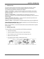
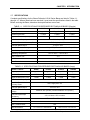
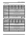
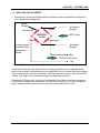
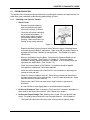
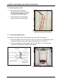
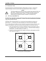
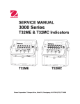
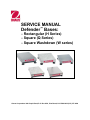
SERVICE MANUAL
Defender™ Bases:
– Rectangular (H Series)
– Square (Q Series)
– Square Washdown (W series)
Ohaus Corporation 19A Chapin Road, P.O. Box 2033, Pine Brook, NJ 07058-2033 (973) 377-9000
SERVICE MANUAL
Defender™ Bases:
– Rectangular (H Series)
– Square (Q Series)
– Square Washdown (W series)
The information contained in this manual is believed to be accurate at the time of publication, but Ohaus
Corporation assumes no liability arising from the use or misuse of this material. Reproduction of this
material is strictly prohibited.
Material in this manual is subject to change.
© Copyright 2008 Ohaus Corporation, all rights reserved.
TM Registered trademark of Ohaus Corporation.
TABLE OF CONTENTS
CHAPTER 1 INTRODUCTION
1.1
1.2
1.3
1.4
1.5
1.6
1.7
1.8
Page No.
Introduction ................................................................................................................1-1
Service Facilities........................................................................................................1-1
Tools and Test Equipment Required .........................................................................1-2
Test Masses Required...............................................................................................1-2
Service Strategy ........................................................................................................1-2
Physical Description: Defender H-Q-W Bases ..........................................................1-2
Specifications.............................................................................................................1-3
How Load Cells Operate............................................................................................1-6
CHAPTER 2 TROUBLESHOOTING
2.1
Troubleshooting .........................................................................................................2-1
2.1.1 Checking Load Cells for Trouble ........................................................................2-1
CHAPTER 3 MAINTENANCE AND REPAIR PROCEDURES
3.1
Preventive Maintenance ............................................................................................3-1
3.1.1 Preventive Maintenance Checklist .....................................................................3-1
3.2 Replacing the Load Cell.............................................................................................3-1
3.3 Overload Stop Adjustments .......................................................................................3-2
CHAPTER 4 TESTING
4.1. Testing .......................................................................................................................4-1
4.2 Load Cell Resistance Checks....................................................................................4-1
4.3 Calibration with an External Indicator ........................................................................4-1
4.4. Consistency Check ....................................................................................................4-2
4.5 Performance Tests ....................................................................................................4-2
4.5.1 Off Center Load (Shift) Test ...............................................................................4-3
4.5.2 Adjusting Off Center Load ..................................................................................4-4
4.5.3 Full Load Test.....................................................................................................4-5
CHAPTER 5 DRAWINGS AND PARTS LISTS
5-1
Defender H-Q-W Bases.............................................................................................5-2
APPENDIX A: GLOSSARY
A-1
Glossary.................................................................................................................... A-1
LIST OF TABLES
1-1
1-2
1-3
1-4
1-5
1-6
3-2.
4-1
4-2
5-1
Specifications for Defender Rectangular Bases (Regular)....................................1-3
Specifications for Defender Rectangular Bases (Large) .......................................1-3
Specifications for Defender Square Bases (Regular)............................................1-4
Specifications for Defender Square Bases (Large) ...............................................1-4
Specifications for Defender Square Washdown Bases (Regular).........................1-5
Specifications for Defender Square Washdown Bases (Large) ............................1-5
Overload Gap Settings For Defender H-Q-W Bases.............................................3-3
Load Cell Resistance Readings ............................................................................4-1
Load Cell Output Readings ...................................................................................4-3
Defender H-Q-W Bases: Housing & Internal Parts ...............................................5-3
(continued next page)
Ohaus Corporation www.ohaus.com
i
Defender™ H-Q-W Series Service Manual
TABLE OF CONTENTS
Page No.
1-1.
1-2
1-3
2-1
3-1
3-2
3-3
3-4
3-5
4-1
4-2
4-3
5-1
LIST OF ILLUSTRATIONS
Typical Strain Gauge Load Cell.............................................................................1-4
Downward force on the Platform bends the beam ................................................1-4
Route of electrical Load Cell input and output.......................................................1-5
Removing plastic shipping tabs.............................................................................2-1
Four Mounting Bolts that secure the Top Frame to the Load Cell.........................3-1
Four Mounting Bolts that secure the Bottom Frame to the Load Cell ...................3-2
Overload Gap Setting............................................................................................3-2
Location of top Overload Stops .............................................................................3-2
Location of bottom Overload Stops .......................................................................3-3
Resistance elements on H and Q series Bases ....................................................4-1
Positions A, B, C and D are Centered...................................................................4-4
Off Center Load adjustment points........................................................................4-5
Defender H-Q-W Bases: Housing & Internal Parts ...............................................5-2
Defender™ H-Q-W Series Service Manual
ii
Ohaus Corporation www.ohaus.com
CHAPTER 1 INTRODUCTION
1.1
INTRODUCTION
This service manual contains the information needed for diagnosis and repair of Ohaus
Defender Square, Rectangular, and Square Washdown Bases (the H-Q-W Series).
The contents of this manual are contained in five chapters:
Chapter 1 Introduction – Contains information regarding service facilities, tools and test
equipment, test masses, specifications, service strategy, and the mechanical and electronic
operation of the Base.
Chapter 2 Troubleshooting – Provides guidelines for evaluating the condition and
performance of a Base unit, and a standard troubleshooting methodology to follow, as well as a
diagnostic guide.
Chapter 3 Maintenance Procedures – Contains preventive maintenance procedures and
disassembly, repair and replacement procedures.
Chapter 4 Testing – Contains guides for operational and performance tests and adjustments.
Chapter 5 Drawings and Parts Lists – Contains exploded views of the Defender Bases and
parts, identifying all serviceable components.
Before servicing the Base, you should be familiar with the Instruction Manual which is packed
with every base.
1.2
SERVICE FACILITIES
To service a Base, the service area should meet the following requirements:
•
Clean and level surface.
•
Away from magnetic fields such as motors or large transformers.
•
Free of vibrations such as fork lift trucks close by, large motors, etc.
•
Stable and level work surface.
•
Not exposed to direct sunlight or radiating heat sources.
Defender™ H-Q-W Series Service Manual
1-1
Ohaus Corporation www.ohaus.com
CHAPTER 1 INTRODUCTION
1.3
TOOLS AND TEST EQUIPMENT REQUIRED
1. Common hand tools
2. Standard electronics tool kit
3. Digital Voltmeter (DVM) capable of reading from 1 mv to 50 V dc.)
4. Megohmeter (50 Volt dc maximum test voltage)
5. Desk magnifier on a stand
6. Ohaus Indicator: Defender 3000, 5000, 7000, or equivalent commercial indicator
7. A calibrated Torque Wrench N.m. – Ft/Lbs
1.4
TEST MASSES REQUIRED
The masses required to test the Ohaus Defender H-Q-W Series Bases when connected to an
Indicator must meet the requirements of ASTM Class 4 or OIML F2. Mass values 3kg to 300kg,
depending on the Base model. The full scale rated capacity of the Base should be used for
Span calibration.
1.5
SERVICE STRATEGY
The Load Cells used in Ohaus Bases are non-repairable. The repair method for the Base is
direct replacement of Load Cells with connecting cable and hardware.
Each base contains the following basic replaceable assemblies: Platform, Load Cell with
Connecting Cable, and Down Stop and mounting hardware. There is an exploded view drawing
of the Base and associated parts list in Chapter 5. This service manual contains sufficient
information to isolate the problem, replace the component, test and restore the Base to
specifications.
1.6
PHYSICAL DESCRIPTION: DEFENDER BASES
Construction
H and Q Series (General Purpose Bases):
Platform – Stainless steel
Frame – Painted Carbon Steel
Load Cell – IP 67 Aluminum
W series (Washdown Bases):
Platform – Fabricated stainless steel
Scale Base – Formed and welded stainless steel
Load Cell – IP 67 Stainless steel
Overloading
Corner Loading – 100% of Full Capacity
Safe Overload – 150% of Full Capacity
Ultimate Overload – 300% of Full Capacity
Operating Environment
Designed to meet OIML 3000e and NTEP 5000d requirements
to operate at a temperature range from –10°C to 40°C /
14°F to 104°F, 0 to 95% relative humidity
Ohaus Corporation www.ohaus.com
1-2
Defender™ H-Q-W Series Service Manual
CHAPTER 1 INTRODUCTION
1.7
SPECIFICATIONS
Complete specifications for the Ohaus Defender H-Q-W Series Bases are listed in Tables 1-1,
through 1-6. When a Base has been serviced, it must meet the specifications listed in the table.
Before servicing the Base, determine what specifications are not met.
TABLE 1-1. SPECIFICATIONS FOR DEFENDER RECTANGULAR BASES (Regular)
MODEL: H Series
D15HR
D30HR
D60HR
15 kg / 30 lb
30 kg / 60 lb
60 kg / 150 lb
Standard Resolution
1:15000
1:15000
1:12000
Approved Resolution (nmax)
1:3000
1:3000
1:3000
Capacity
Safe Overload Capacity
150% of capacity
Load Cell Protection/ Accuracy Class
IP67, single point / C3
Load Cell Rated Output
2 mV/V ± 10%
Load Cell Excitation Voltage
Maximum 20V (AC/DC) / Recommended 5~15V (AC/DC)
Load Cell Input/Output Resistance
410 ± 10 ohms / 350 ± 4 ohms
Operating Temperature
14°F to 104°F / -10°C to 40°C
Shift Tolerance new
±1d
Shift Tolerance Maint.
±2d
Base Dimensions
12 x 14 in. / 30.5 x 35.5 cm
TABLE 1-2. SPECIFICATIONS FOR DEFENDER RECTANGULAR BASES (Large)
MODEL: H Series
D60HL
D100HL
D150HX
D300HX
60 kg / 150 lb
100 kg / 250 lb
150 kg / 300 lb
300 kg / 600 lb
Standard Resolution
1:12000
1:10000
1:15000
1:15000
Approved Resolution (nmax)
1:3000
1:3000
1:3000
1:3000
Capacity
Safe Overload Capacity
150% of capacity
Load Cell Protection/
Accuracy Class
IP67, single point / C3
Load Cell Rated Output
Load Cell Excitation
Voltage
2 mV/V ± 10%
Maximum 20V (AC/DC) / Recommended 5~15V (AC/DC)
Load Cell Input/Output
Resistance
410 ± 10 ohms / 350 ± 4 ohms
Operating Temperature
14°F to 104°F / -10°C to 40°C
Shift Tolerance new
±1d
Shift Tolerance Maint.
±2d
Base Dimensions
15.7 x 19.7 in. / 40 x 50 cm
Defender™ H-Q-W Series Service Manual
1-3
16.5 x 21.6 in. / 42 x 55 cm
Ohaus Corporation www.ohaus.com
CHAPTER 1 INTRODUCTION
1.7
SPECIFICATIONS
TABLE 1-3. SPECIFICATIONS FOR DEFENDER SQUARE BASES (Regular)
MODEL: Q Series
D10QR
D15QR
D25QR
D30QR
D50QR
10 kg / 25 lb
15 kg / 30 lb
25 kg / 50 lb
30 kg / 60 lb
50 kg / 100 lb
Standard Resolution
1:10000
1:15000
1:12500
1:15000
1:10000
Approved Resolution (nmax)
1:5000
1:3000
1:5000
1:3000
1:5000
Capacity
Safe Overload Capacity
150% of capacity
Load Cell Protection/
Accuracy Class
IP67, single point / C3
Load Cell Rated Output
2 mV/V ± 10%
Load Cell Excitation Voltage
Maximum 20V (AC/DC) / Recommended 5~15V (AC/DC)
Load Cell Input/Output
Resistance
410 ± 10 ohms / 350 ± 4 ohms
Operating Temperature
14°F to 104°F / -10°C to 40°C
Shift Tolerance new
±1d
Shift Tolerance Maint.
±2d
Base Dimensions
18 x 18 in. /
457 x 457 mm
12 x 12 in. / 305 x 305 mm
TABLE 1-4. SPECIFICATIONS FOR DEFENDER SQUARE BASES (Large)
MODEL: Q Series
D60QL
D100QL
D150QL
D250QX
D300QX
60 kg / 150 lb
100 kg / 250 lb
150 kg / 300 lb
250 kg / 500 lb
300 kg / 600 lb
Standard Resolution
1:12000
1:10000
1:15000
1:12500
1:15000
Approved Resolution (nmax)
1:3000
1:5000
1:3000
1:5000
1:3000
Capacity
Safe Overload Capacity
150% of capacity
Load Cell Protection/ Accuracy
Class
IP67, single point / C3
Load Cell Rated Output
Load Cell Excitation Voltage
2 mV/V ± 10%
Maximum 20V (AC/DC) / Recommended 5~15V (AC/DC)
Load Cell Input/Output
Resistance
410 ± 10 ohms / 350 ± 4 ohms
Operating Temperature
14°F to 104°F / -10°C to 40°C
Shift Tolerance new
±1d
Shift Tolerance Maint.
±2d
Base Dimensions
Ohaus Corporation www.ohaus.com
18 x 18 in. / 457 x 457 mm
1-4
24 x 24 in. / 61 x 61 cm
Defender™ H-Q-W Series Service Manual
CHAPTER 1 INTRODUCTION
1.7
SPECIFICATIONS
TABLE 1-5. SPECIFICATIONS FOR DEFENDER SQUARE WASHDOWN BASES (Regular)
MODEL: W Series
D10WR
D15WR
D25WR
D30WR
D50WR
10 kg / 25 lb
15 kg / 30 lb
25 kg / 50 lb
30 kg / 60 lb
50 kg / 100 lb
Standard Resolution
1:10000
1:15000
1:12500
1:15000
1:10000
Approved Resolution (nmax)
1:5000
1:3000
1:5000
1:3000
1:5000
Capacity
Safe Overload Capacity
150% of capacity
Load Cell Protection/
Accuracy Class
IP67, single point / C3
Load Cell Rated Output
Load Cell Excitation Voltage
2 mV/V ± 10%
Maximum 20V (AC/DC) / Recommended 5~15V (AC/DC)
Load Cell Input/Output
Resistance
410 ± 10 ohms / 350 ± 4 ohms
Operating Temperature
14°F to 104°F / -10°C to 40°C
Shift Tolerance new
±1d
Shift Tolerance Maint.
±2d
Base Dimensions
18 x 18 in. /
457 x 457 mm
12 x 12 in. / 305 x 305 mm
TABLE 1-6. SPECIFICATIONS FOR DEFENDER SQUARE WASHDOWN BASES (Large)
MODEL: W Series
D60WL
D100WL
D150WL
D250WX
D300WX
60 kg / 150 lb
100 kg / 250 lb
150 kg / 300 lb
250 kg / 500 lb
300 kg / 600 lb
Standard Resolution
1:12000
1:10000
1:15000
1:12500
1:15000
Approved Resolution (nmax)
1:3000
1:5000
1:3000
1:5000
1:3000
Capacity
Safe Overload Capacity
150% of capacity
Load Cell Protection/
Accuracy Class
IP67, single point / C3
Load Cell Rated Output
Load Cell Excitation Voltage
2 mV/V ± 10%
Maximum 20V (AC/DC) / Recommended 5~15V (AC/DC)
Load Cell Input/Output
Resistance
410 ± 10 ohms / 350 ± 4 ohms
Operating Temperature
14°F to 104°F / -10°C to 40°C
Shift Tolerance new
±1d
Shift Tolerance Maint.
±2d
Base Dimensions
18 x 18 in. / 457 x 457 mm
Defender™ H-Q-W Series Service Manual
1-5
24 x 24 in. / 61 x 61 cm
Ohaus Corporation www.ohaus.com
CHAPTER 1 INTRODUCTION
1.8
HOW LOAD CELLS OPERATE
Load Cells are devices that convert force into a signal. Defender Bases have a Strain Gauge
Load Cell, which is made from a metal beam with holes drilled in it. Strain gauges are affixed to
the beam at the top and bottom to measure changes in the beam due to deflection. The gauges
are bonded very securely to the metal, where they sense very small deflections in the metal
caused by the load being applied to the cell. Because the signal levels are very small, the
circuit is protected from all outside influences such as moisture, physical damage, or electrical
interference.
Attachment points to
Platform
Strain Gauges
Beam
Printed Circuit Board
completing Wheatstone
Bridge circuit
Holes drilled in Strain
Gauge Load Cell
Figure 1-1. Strain Gauge Load Cell.
The strain gauges are wired into a Wheatstone Bridge Circuit. (See Figure 1-2.)
+
–
Strain Gauge
Strain Gauge
Strain Gauge
Strain Gauge
–
+
Force
Printed Circuit Board (PCB )
completing Wheatstone
Bridge circuit
Wheatstone Bridge Circuit
Figure 1-2. Downward force on the Platform bends the beam, causing two gauges to stretch
and two to compress in opposition, changing the electrical resistance of the circuit.
At zero load, all strain gauges are unstressed. Weight placed on the Platform bends the
beam, causing two gauges to stretch and two to compress in opposition, changing the
electrical resistance of the circuit.
Ohaus Corporation www.ohaus.com
1-6
Defender™ H-Q-W Series Service Manual
CHAPTER 1 INTRODUCTION
1.8
HOW LOAD CELLS OPERATE
The difference in the output signal before and after the mass was placed on the platform is
taken, interpreted and displayed.
Strain
Gauges
+Excitation
(Supply)
Tension
Compression
INPUT(volts)
LOADCELL
2 mV/V
Tension
Compression
4 strain gauges
connected as a
Wheatstone
Bridge
–Excitation
(Supply)
+Sig
OUTPUT (milli volts)
–Sig
Figure 1-3. Route of electrical Load Cell input and output through Wheatstone Bridge circuit.
A Load Cell is a force sensor, which receives a voltage (excitation) from a regulated power
source in the Indicator, and sends back a low-voltage milli-volt (mV) relative to the force applied.
The Load Cell signal is read by the Indicator, which converts it to a numeric value and shows it
visually. This output value increases as weight is loaded to the Load Cell.
For example, a 500kg Load Cell with 2mV/V output and 5V excitation would have a change of
0.02mV per kg change in the load, that is, 10mV/500=0.02mV per kg. At a load of 250kg the
signal voltage would thus increase by 5mV from the value measured at no load.
Defender™ H-Q-W Series Service Manual
1-7
Ohaus Corporation www.ohaus.com
CHAPTER 1 INTRODUCTION
Ohaus Corporation www.ohaus.com
1-8
Defender™ H-Q-W Series Service Manual
CHAPTER 2 DIAGNOSTIC GUIDE
2.1
TROUBLESHOOTING
This section of the manual provides guidelines for evaluating the condition and performance of a
scale Base, and a standard troubleshooting methodology to follow.
2.1.1
Checking Load Cells for Trouble
1. Visual Check:
–
Remove the plastic shipping
tabs from between the upper
and lower Housings, if present.
–
Clean the unit before evaluating
any mechanical problems. In
some cases, debris may have
accumulated inside the Base
Housing. Make sure there is no
buildup of any foreign material.
Figure 2-1. Removing plastic shipping tabs.
–
Examine the Base Housing for dents, bent Platform or signs of physical abuse
that could cause the Base to malfunction. Make sure that the proper Platform is
supplied with the Base. Replace all damaged parts. See Chapter 5 for parts
identification.
–
Remove the Platform from the Base. Check that the Overload Stops are not
touching the Top Plate. (See Figure 5-1, Chapter 5.) This would restrict
movement, causing improper operation of the Base. If the Overload Stops are
improperly set, adjust them. (See Section 3.3.)
–
Check the metal surfaces of the Platform. All surfaces should be parallel.
If the platform is deformed, it should be replaced.
–
Check the cables leading to the Load Cell for cuts, abrasions or other signs of
excessive wear and tear.
–
Check for a bent or twisted Load Cell: Place the top surface and then each of
the sides of the Load Cell on a flat surface, to see if it rests flat and even. A gap
indicates a bent or twisted Load Cell.
–
Examine the Load Cell for corrosion due to high humidity or exposure to
chemicals.
–
A Load Cell that is even slightly bent or corroded should be replaced.
2. Perform a Resistance Test, to determine if the Load Cell is severely damaged or a
short circuit to the frame has occurred. (See Chapter 4 for details.)
3. Perform an Output Voltage Test: Measure the no load, 50% load and full load
output. The reading should meet the Load Cell specifications. (See Chapter 4.)
–
The Load Cell output should be very close to linear over its capacity range.
Defender™ H-Q-W Series Service Manual
2-1
Ohaus Corporation www.ohaus.com
CHAPTER 2 DIAGNOSTIC GUIDE
Ohaus Corporation www.ohaus.com
2-2
Defender™ H-Q-W Series Service Manual
CHAPTER 3 MAINTENANCE AND REPAIR PROCEDURES
3.1
PREVENTIVE MAINTENANCE
Ohaus bases should be carefully handled, stored in a clean, dry area, and cleaned periodically.
Follow these precautionary steps:
–
When a base has had chemicals or liquids spilled on it, all exterior surfaces should be
cleaned as soon as possible with warm water on a damp cloth.
–
Do not leave a mass on the base when it is not in use.
–
Allow time for the base to stabilize after moving it from an area which is at a different
temperature than the area where it is to be operated. Allow one hour for each 5°F
(2.7°C) temperature change before using the base.
3.1.1
Preventive Maintenance Checklist
The scale should be inspected and checked regularly, as follows:
1. Clean the base.
2. Remove the Platform to inspect and clean the area beneath the Platform.
CAUTION
DO NOT USE CHEMICAL CLEANERS OR SOLVENTS OF ANY TYPE.
SOME CLEANERS ARE ABRASIVE AND MAY AFFECT THE BASE’S FINISH.
3. Check the Load Cell cable for broken or damaged insulation.
4. Make a visual inspection as detailed in Chapter 2.
3.2
Replacing the Load Cell
A Load Cell that is even slightly bent or corroded should be replaced. The Load Cell may also
need to be replaced because of instability, or because the scale does not calibrate or repeat, or
because it is physically broken.
1. Remove the scale Platform and
disconnect the Base from the Indicator.
2. Remove the four Load Cell Mounting
Bolts and washers that secure the Top
Frame to the Load Cell.
3. Set the Top Frame and the Load Cell
Spacer aside.
Figure 3-1. Four Mounting Bolts that secure
the Top Frame to the Load Cell.
Defender™ H-Q-W Series Service Manual
3-1
Ohaus Corporation www.ohaus.com
CHAPTER 3 MAINTENANCE AND REPAIR PROCEDURES
3.2
Replacing the Load Cell
4. Remove the bottom Load Cell
Mounting Bolts, washers and spacer.
The Load Cell assembly can now be
removed from the Lower Frame.
5. Install the new Load Cell following
steps 1 through 4 in reverse order.
Figure 3-2. Four Mounting Bolts that secure
the Bottom Frame to the Load Cell.
3.3
Overload Stop Adjustments
The Overload Stop gaps must be checked and reset if the Load Cell is replaced.
1. Remove the Platform and loosen the Jam Nuts, first on the four Overload Stops on the
top side of the Frame, then on the bottom. (See Figures 3-3, 3-4 and 3-5.)
2. Use the appropriate size feeler gauge in the Gap (see Table 3-1), and turn the set
screws until a slight drag is felt on the feeler gauge.
Jam Nut
Set Screw
Gap
Overload Stop
Figure 3-3. Overload Gap Setting.
Figure 3-4. Location of top Overload Stops.
Ohaus Corporation www.ohaus.com
3-2
Defender™ H-Q-W Series Service Manual
CHAPTER 3 MAINTENANCE AND REPAIR PROCEDURES
3.3
Overload Stop Adjustments
3. Tighten the Jam Nut and re-check
the Gap.
4. Re-adjust if necessary.
5. Cover the Platform and check for full
capacity. (See Table 3-1 for Gap
settings.)
Figure 3-5. Location of bottom Overload Stop.
TABLE 3-1. OVERLOAD GAP SETTINGS FOR DEFENDER H-Q-W BASES
Model
Overload Stop (Corner)
Overload Stop (Center)
D15HR
2mm (0.78in.)
0.5mm(0.02in.)
D30HR
2mm (0.78in.)
0.5mm(0.02in.)
D60HR
3mm (0.118in.)
0.5mm(0.02in.)
D60HL
3mm (0.118in.)
0.75mm(0.03in.)
D100HL
3mm (0.118in.)
0.75mm(0.03in.)
D150HX
4mm (0.157in.)
1mm (0.04in.)
D300HX
4mm (0.157in.)
1mm (0.04in.)
D10QR
2mm (0.78in.)
0.8mm (0.3in.)
D25QR
2mm (0.78in.)
0.8mm (0.3in.)
D50QL
3mm (0.11in.)
1mm (0.4in.)
D100QL
4mm (0.157in.)
1mm (0.4in.)
D250QX
6mm (0.23in.)
1mm (0.4in.)
D10WR
2mm (0.78in.)
0.8mm (0.31in.)
D25WR
2mm (0.78in.)
0.8mm (0.31in.)
D50WL
3mm (0.11in.)
1mm (0.04in.)
D100WL
4mm (0.157in.)
1mm (0.04in.)
D250WX
6mm (0.23in.)
1mm (0.04in.)
Defender™ H-Q-W Series Service Manual
3-3
Ohaus Corporation www.ohaus.com
CHAPTER 3 MAINTENANCE AND REPAIR PROCEDURES
Ohaus Corporation www.ohaus.com
3-4
Defender™ H-Q-W Series Service Manual
CHAPTER 4 TESTING
4.1
TESTING
Before and after servicing a Defender Base, conduct Load Cell Resistance Checks, Calibration
using an external Indicator, and Performance Tests to confirm that the base meets
specifications. Allow time for the base to stabilize after moving it from an area which is at a
different temperature than the area where it is to be operated. Allow one hour for each 5°F
(2.7°C) temperature change before using the base.
The following tests require a Digital Multimeter, an Indicator and hand tools. The Digital DC
Voltmeter should have a reading range from 1 mV to 50 V full-scale. It should be capable of
reading differences of one micro-volt per increment. The indicator can be either the Ohaus
Defender 5000, or an equivalent commercial indicator.
NOTE:
Make sure the test area is free from drafts and that the base rests on a level and
vibration-free surface.
4.2
Load Cell Resistance Checks
Use an ohm-meter to measure across each pair of wires, and compare the results with Table 41. The Load Cell must be completely disconnected from the Indicator and at no load when
these tests are made.
Note: The cable fitting for the H and Q series Bases has
seven pins, as shown in Figure 4-1. Pin 1 is EX+, Pin 3
is S+, Pin 5 is S –, Pin 7 is EX –. The wires are color
coded on the W series. The Load Cell label shows the
wire color code for the Load Cell.
S–
S+
3
5
7
1
EX+
EX –
Figure 4-1. Resistance elements
on H and Q series Bases.
In addition to the four resistance elements which make up the Wheatstone Bridge, there are
commonly one or two resistors in the excitation lines. The resistance across the excitation wires
is usually the highest resistance measured across any two wires.
If the resistance readings are in the range specified, skip to the next section. If they are
incorrect – for example, outside the expected range, open circuit or short-circuit across any two
wires – the likely causes are a damaged or faulty Load Cell or incorrect or faulty wiring. If the
Load Cell is defective, replace it. (See Chapter 3.)
TABLE 4-1. LOAD CELL RESISTANCE READINGS (in Ohms)
Models
Ex+ to Ex– S+ to S– Ex+ to S–
Ex+ to S+
Ex– to S+ Ex– to S–
H Series
410 ± 10
350 ± 4
313 ± 10
313 ± 10
262.5 ± 10 262.5 ± 10
Q Series
410 ± 10
350 ± 4
313 ± 10
313 ± 10
262.5 ± 10 262.5 ± 10
W Series
387 ± 10
350 ± 4
297 ± 10
297 ± 10
262.5 ± 10 262.5 ± 10
Defender™ H-Q-W Series Service Manual
4-1
Ohaus Corporation www.ohaus.com
CHAPTER 4 TESTING
4.3
Calibration with an External Indicator
1. Install the Load Cell. (See Section 3.2.)
2. Connect the excitation, signal shield and sensing wires (if provided), to the Indicator.
Calibrate the Indicator to read the load in the units required, for example, kilograms or
grams. (Consult the Indicator instruction manual for calibration procedures.) For
calibration mass weights, see Table 1-1, in Chapter 1.
3. Check that the Indicator is reading correctly over a range of values.
4.4
Consistency Check
To check the system prior to installation, make the following measurements. (Also make these
checks if the Load Cell will not calibrate, or if the Indicator does not read correctly, or is giving
unstable readings.)
1. Using a voltmeter, measure and record the excitation voltage supplied by the Indicator.
Most Ohaus indicators supply 5 volts dc for the excitation voltage.
2. Using an mV meter, measure and record the signal voltage with no load on the base.
CAUTION:
IN THE NEXT STEP, DO NOT OVERLOAD THE BASE BEYOND FULL
CAPACITY RATING.
3. Using an mV meter, measure and record the signal voltage at the loads shown in
Table 4-2.
4. Compare the measured output readings with the theoretical values from the Load Cell
data. (See Table 4-2.)
Ohaus Corporation www.ohaus.com
4-2
Defender™ H-Q-W Series Service Manual
CHAPTER 4 TESTING
4.4
Consistency Check
TABLE 4-2. LOAD CELL OUTPUT READINGS (in mV with 5V Excitation)
Model/Capacity
Zero Load
50% Load
100% Load
D15HR/15kg
1.3 ± 1.0
Zero + 2.8
Zero + 5.6
D30HR/30kg
1.1 ± 1.0
Zero + 2.55
Zero + 5.1
D60HR/60kg
0.7 ± 1.0
Zero + 3.1
Zero + 6.2
D60HL/60kg
0.7 ± 1.0
Zero + 3.1
Zero + 6.2
D100HR/100kg
1.3 ± 2.0
Zero + 2.7
Zero + 5.4
D150HR/150kg
0.53 ± 2.0
Zero + 2.5
Zero + 5
D300HL/300kg
0.34 ± 2.0
Zero + 3
Zero + 6
D10QR/10kg
4.3 ± 2.0
Zero + 2.3
Zero + 4.7
D25QR/25kg
1.6 ± 2.0
Zero + 2.8
Zero + 5.6
D50QR/50kg
1.7 ± 2.0
Zero + 2.4
Zero + 4.8
D100QL/100kg
1.3 ± 2.0
Zero + 2.7
Zero + 5.4
D250QX/250kg
0.34 ± 2.0
Zero + 2.5
Zero + 5
D10WR/10kg
4.3 ± 2.0
Zero + 2.3
Zero + 4.7
D25WR/25kg
1.6 ± 2.0
Zero + 2.8
Zero + 5.6
D50WR/50kg
1.7 ± 2.0
Zero + 2.4
Zero + 4.8
D100WL/100kg
1.3 ± 2.0
Zero + 2.7
Zero + 5.4
D250WX/250kg
0.34 ± 2.0
Zero + 2.5
Zero + 5
Defender™ H-Q-W Series Service Manual
4-3
Ohaus Corporation www.ohaus.com
CHAPTER 4 TESTING
4.5
Performance Tests
Accurate performance of the Defender Bases is determined by two tests. Compare the
displayed readings with the tolerances listed in the Specifications Tables in Chapter 1.
NOTE:
The following performance tests are used to evaluate base operation before and
after repairs. The base must meet the requirements specified in each test as
well as the specifications listed in Table 1-2. Before proceeding with the
following tests, the indicator should be calibrated. (See Section 4.3.)
4.5.1
Off Center Load (Shift) Test
The Shift Test is made before and after a Base has had the Load Cell replaced and adjustments
have been made that affect its performance. The Shift Test verifies that all sections of the Base
weigh within specified tolerance.
If the Base does not pass the Shift Test, verify that the Overload Stops are properly set.
(See Section 3.1.) If the Shift Test cannot be passed, the Load Cell must be replaced.
Prior to starting this test, the Base must be connected to a properly functioning Indicator, with
capacity and readability values set according to the specifications for the Base under test.
1. Place test weights equal to one third of the Base's capacity sequentially at each of
the positions A, B, C, and D, as shown in Figure 4-1. Note the indicator reading at
each position. (For Base capacity, see Table 1-1.)
2. Check the variation between mass weights and indicator reading against specified
Shift Tolerance in Table 1-1.
A
B
C
D
Figure 4-2. Positions A, B, C and D are centered
at each quarter of the base platform.
Ohaus Corporation www.ohaus.com
4-4
Defender™ H-Q-W Series Service Manual
CHAPTER 4 TESTING
4.5.2
Adjusting Off Center Load
If the Off Center Load (Shift) is excessive, perform adjustment as follows:
Top view of Load Cell
Side view of Load Cell
2
3
1
4
Figure 4-3. Off Center Load adjustment points.
1. Place the test weight in the center of the Platform.
2. Tare the indicator.
3. Move the weight to point A and record the reading.
4. Move the weight to point B and record the reading.
5. Move the weight to point C and record the reading.
6. Move the weight to point D and record the reading.
7. If the reading at point A is negative, file at points 1 and 4 AT AN ANGLE.
8. If the reading at point B is negative, file at points 1 and 2 STRAIGHT ACROSS.
9. If the reading at point C is negative, file at points 2 and 3 AT AN ANGLE.
10. If the reading at point D is negative, file at points 3 and 4 STRAIGHT ACROSS.
Note: It is not recommended that you try to adjust more than –5 counts if the beam has
been filed already. If the beam has not been filed previously, you can adjust –10 counts.
Remember, when filing you are weakening the beam. File a little at a time.
Defender™ H-Q-W Series Service Manual
4-5
Ohaus Corporation www.ohaus.com
CHAPTER 4 TESTING
4.5.3
Full Load Test
1. After the Off Center Load Test has been passed, test the Base’s full capacity
according to the Specification Tables 1-1 through 1-6. The Base must meet all
specifications as listed.
2. If the Base fails the Full Load Test, check and set the Overload Stops.
(See Section 3.3.)
Ohaus Corporation www.ohaus.com
4-6
Defender™ H-Q-W Series Service Manual
CHAPTER 5 PARTS LISTS & DIAGRAMS
This section of the manual contains exploded views for the Defender H-Q-W Bases. The
exploded view drawings are designed to identify the parts which can be serviced in the field.
NOTE:
In all cases where a part is replaced, the base must be thoroughly checked after
the replacement is made. The base MUST meet the parameters of all applicable
specifications in this manual.
If further technical information is needed, please contact your local Ohaus office or:
Ohaus Corporation, www.ohaus.com
19A Chapin Road
P.O. Box 2033
Pine Brook, NJ 07058-2033 USA
Tel: 973-377-9000
Fax: 973-593-0359
In the United States call toll free, 800-526-0659 between 8:00 a.m. and 6:00 p.m. EST.
Defender™ H-Q-W Series Service Manual
5-1
Ohaus Corporation www.ohaus.com
CHAPTER 5 PARTS LISTS & DIAGRAMS
5.1
DEFENDER RECTANGULAR (H) BASES: PARTS
Figure 5-1. Defender Rectangular (H) Bases: Parts
Ohaus Corporation www.ohaus.com
5-2
Defender™ H-Q-W Series Service Manual
CHAPTER 5 PARTS LISTS & DIAGRAMS
5.1
DEFENDER RECTANGULAR (H) BASES: PARTS
TABLE 5-1. DEFENDER RECTANGULAR (H) BASES: PARTS
Drawing Item
Description
1
Pan
2
Rubber Center Load Pad
3
Rubber Corner Load Pad
4
Overload Stop Jam Nuts and Set Screws
5
Load Cell Mounting Bolt
6
Load Cell
7
Load Cell Mounting Washers
8
Level Kit
9
Leveling Feet
When replacement parts are needed, refer to the spare part list for the model you are servicing.
Parts lists are available from your local Ohaus office, or visit Ohaus.com.
Defender™ H-Q-W Series Service Manual
5-3
Ohaus Corporation www.ohaus.com
CHAPTER 5 PARTS LISTS & DIAGRAMS
5.2
DEFENDER SQUARE (Q & W) BASES: PARTS
1
7
4
5
4
3
2
6
8
5
4
7
9
Figure 5-2. Defender Square (Q & W) Bases: Parts
Ohaus Corporation www.ohaus.com
5-4
Defender™ H-Q-W Series Service Manual
CHAPTER 5 PARTS LISTS & DIAGRAMS
5.2
DEFENDER SQUARE (Q & W) BASES: PARTS
TABLE 5-1. DEFENDER SQUARE (Q & W) BASES: PARTS
Drawing Item
Description
1
Pan
2
Rubber Center Load Pad
3
Rubber Corner Load Pad
4
Overload Stop Jam Nuts and Set Screws
5
Load Cell Mounting Bolt
6
Load Cell
7
Load Cell Mounting Washers
8
Level Kit
9
Leveling Feet
Defender™ H-Q-W Series Service Manual
5-5
Ohaus Corporation www.ohaus.com
CHAPTER 5 PARTS LISTS & DIAGRAMS
Ohaus Corporation www.ohaus.com
5-6
Defender™ H-Q-W Series Service Manual
APPENDIX A GLOSSARY
APPENDIX A. GLOSSARY
Ohaus Load Cells contain a specification label on the Load Cell itself.
Compensated Temperature Range
The range of temperatures over which the output from the cell is compensated. If used
outside this range the output cannot be guaranteed to follow the specifications.
Environmental Protection
IP rating against moisture and dust, for example, IP 65.
Excitation
Voltage applied to the Exe+ and Exe– leads of the load cell.
Input Resistance
The resistance measured across Exe+ and Exe– with load cell disconnected and
no load.
Insulation Resistance
Normally measured at 50 V dc, this is the minimal resistance between the metal body of
the load cell and any of its electrical connections.
Mechanical Failure
The load at which the cell is likely to fail mechanically, that is, break or deform.
mV/V
Usually the output from a load cell will be approximately 0m V at zero load, though
typically there may be a small offset voltage at zero load. Over the full rated capacity of
the load cell, the mV output will change. The amount by which it changes depends upon
the resistance change in the cell and on the excitation voltage applied. Since the load
cell manufacturer does not know what excitation voltage will be applied to the cell, rather
than quote the V output over full range, they will quote the milli-Volt output per volt of
excitation, or in its short form, mv/V. Most Ohaus Indicators provide an excitation voltage
of 5 Volts dc.
Output Resistance
The resistance measured across S+ plus and S– with load cell disconnected and
no load.
Overload Capacity
The maximum load that can be applied without permanent damage. Loads in excess of
maximum capacity will cause damage to the load cell.
Rated Capacity
The maximum load over which the load cell will operate within its specifications.
Rated Output
The nominal mV/V output of the load cell.
Ultimate Capacity
This is a percentage setting, usually 300% of full capacity.
Zero Balance
The output of the load cell at no load, normally quoted as a percentage of full load. Also
known as zero offset.
Defender™ H-Q-W Series Service Manual
A-1
Ohaus Corporation www.ohaus.com
APPENDIX A GLOSSARY
Ohaus Corporation www.ohaus.com
A-2
Defender™ H-Q-W Series Service Manual
*80252596*
P/N 80252596 SERVICE MANUAL: DEFENDER™ H-Q-W SERIES BASES