1
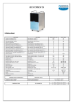
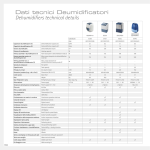
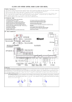
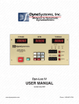
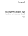
AQUADRY 28
1.Data sheet
2.Control panel keys and display
S1
S4
S6
DL3-DL4
Relative
Humidity
view
DL1-DL2
Room air
temperature
view
SW5
SW1
SW2
SW3
SW4
S1:Dehumidification
S4:Full water tank/No water tank.If blinking with frequency of 1.25Hz,continuous discharge function is
enabled
S6:Purifying mode
SW1:Turn on/Stand-by key
SW2:Mode selection key.
SW3:Humidity increasing key (value between 30% and 90%)
SW4:Humidity decreasing key (value between 30% and 90%)
SW5:Room humidity/temp. key
DL1,DL2,DL3,DL4: In normal working operations,they display the Set Temperature and Set Relative
Humidity values respectively (according to the function selected) both in blinking mode and with duration of
5 seconds.Furthermore following information can be shown:
Digit DL1 and DL2
Digit DL3 and DL4
Corresponding information
OFF
30% - 90%
6°C - 30°C blinking
30% - 90% blinking
OFF
Hr blinking
Humidity sensor / room air NTC sensor malfunction
OFF
tE blinking
Evaporator NTC sensor malfunction
OFF
LO blinking
Low temperature alarm
-9°C – 50°C
At
Autotest mode, evaporator temperature value
Co
20 - 50
Setup mode: compressor defrosting ON time
Cf
3 - 15
Setup mode: compressor minimum OFF time
Ft
-9 - 9
Setup mode: frost accumulation temperature
St
0-9
Setup mode: end of defrosting temperature
tC
20 - 40
Relative humidity set value
Room air Temperature and relative humidity measured
Setup mode: set point temperature in combined mode
3.Buzzer and backlight
Activation mode
Corresponding information
Single short pulse
Keys pressed on control board confirmation
Two short pulses
System activation (through SW1)
Three short pulses
Parameter EEprom writing confirmation
Five short pulses
Autotest and Set-up modes activation
Intermittent for 15 seconds
Tank micro switch opening
Probe malfunctions
Evaporator exchanger low temperature malfunction
-
-
As soon as the tank switch opens the unit has to switch-off all the active loads (except the fan whose
switching off has to be delayed by 30 seconds), switch-on of the corresponding symbol in fixed mode
and enable an intermittent acoustic signal for 15 seconds; press any key with the acoustic alarm active or
re-close the microswitch to silence the alarm.
The board confirms any command by a brief acoustic signal and switching on the LCD backlight for 10
seconds.
4.Working modes description
4.1 STAND-BY MODE
This mode can be selected by pressing SW1 key on the control board, and is signalled as shown on par. 2.
In this condition, if the key is pressed again, all the functions previously selected are restored (operating
mode, set-point, etc.).
When switching to stand-by mode all board outputs are switched OFF, but if compressor was active, the fan
only continues to run for 30 seconds further before stopping.
In STAND-BY mode (and only in this mode) it is possible to enter the parameter programming mode where
new parameter values can be stored in eeprom (see related paragraph).
4.2 AIR CLEANING MODE
When selected by SW2 (see par.2) the fan is switched on, while is switched off only in the following cases:
the tank switch opens or any alarm occurs.
When this function is selected, the symbol S6 is switched ON, while digits DL-DL2 and DL3-DL4 show the
actual room temperature and Relative Humidity values acquired (button SW5 is disabled).
The fan speed is the only one available (power board output FAN1).
4.3 DEHUMIDIFICATION MODE
Selected by SW2 and signalled as shown on par. 2.
Compressor and fan (power board output FAN1) are switched on if the minimum OFF time (Cf) has elapsed
and if the relative humidity value is higher than the set point + 3%; compressor and fan remain ON as long
as the relative humidity value is above the set point – 3%; when below the set point – 3%, compressor and
fan switch off (the fan is switched-off 30 seconds later than the compressor) and remain off for a minimum
time equal to Cf (measured from the compressor shut down), at the end of which the compressor and the fan
are switched back on again if the relative humidity value is greater than the set point +3%.
The relative humidity (RH) set point can be adjusted from 30% to 90% in steps of 5%. By pressing the UP
(SW3) or DOWN (SW4) keys the set point value is increased or decreased by 5%.
5.Other functions and modes
5.1 Auto-recovery function
The ON/OFF status, the set point, the operating mode (including tank switch inhibition) are saved in
EEprom memory. After a black-out or a power mains failure the unit recovers all operations previously set
without observing any compressor Cf OFF time.
5.2 Compressor switching
Compressor can be switched ON only when Cf minutes have elapsed starting from previous compressor
shut down.
5.3 Defrosting function
When a frost condition occurs (evaporator temperature < Ft and compressor ON) the compressor remains on
for a maximum time equal to Co minutes, then defrosting takes place (fan on at minimum speed, resistor not
active, compressor off) which terminates when the pre-set temperature St is reached (evaporator temperature
> St), compatibly with the minimum compressor OFF duration Cf (defrosting interval cannot be shorter than
Cf minutes).
If frost condition is detected and RH set point is reached within Co minutes, the compressor has to be
stopped but the fan remains on until the defrosting end temperature is reached.
5.4 Inhibition of Tank Full switch
The tank full switch is ignored: this function is accessed only if the level switch is open (tank full or absent)
by keeping the SW3+SW4 keys pressed for 3 seconds; the S4 symbol blinking indicates that the function is
active. The function is automatically terminated when the level switch is closed.
5.5 Autotest mode
When the unit is in Stby mode, by pressing the keys SW4+SW5 for 3 seconds (SW4 first), the following
sequence is started:
- all LCD symbols are switched ON for 3 seconds;
- the SW release is shown for 3 seconds;
- both fan and compressor are switched ON, the LCD shows the code At on digits DL3 and DL4 and
evaporator probe temperature on digits DL1 and DL2.
- The compressor remains ON continuously, regardless of the RH set point and tank microswitch
condition; the defrosting function is disabled and compressor can be powered even if Cf minutes have
not elapsed from previous compressor shut down.
The tank level symbol (S4) is switched ON if the tank is absent/full (microswitch open), and remains OFF if
the tank is present (board input closed).
By pressing the key SW5 the unit shows the measured room air temperature and relative humidity values
(like during normal operations)
Press the stand-by key (SW1) or disconnect the power supply to quit the auto test mode.
5.6 Setup mode
By pressing the keys SW5+SW3 for 3 seconds in stand-by mode you access the setup: by pressing key SW5
you go to the next parameter, SW5+SW3 or SW5+SW4 increase or decrease the value, when the SW5 key
is released the current value is stored in the memory.
In order to quit the setup mode, press the SW1 key or disconnect the power supply.
The default values shown in the table below are programmed during the electronics test process.
Mnemonic
Range
scheduled
Parameters set
Description
Co
20 - 50 min
20
Compressor in defrosting ON time
Cf
3 - 15 min
3
Compressor minimum OFF time
Ft
-9 – 9 °C
1
Frost accumulation temperature
St
0 – 9 °C
3
End of defrosting temperature
tC
20 – 40°C
26
Temperature set point in combined mode
6.ALARMS
6.1 PROBES ALARM
Any failures in the probes are displayed by Hr or tE blinking for the humidity sensor probe/ambient probe
and evaporator probe respectively; in the case of a failure in the probes all the loads are de-activated (except
the fan whose switching off has to be delayed by 30 seconds) and an intermittent acoustic signal is emitted
(which can be silenced by pressing any key) with duration of 15 seconds.
The humidity probe signals the failure even if it measures a room relative humidity percentage below 22%, a
condition in which the unit must be deactivated. Operation is automatically restored as soon as the relative
humidity rises back above 22%.
6.2 LOW TEMPERATURE ALARM
If after 30 minutes of operation in defrosting mode (compressor stopped and fan working) the evaporator
temperature does not exceed St, then the fan is stopped, the display shows the alarm code LO blinking and
an emission of an intermittent acoustic signal is enabled (which can be silenced by pressing any key) with
duration of 15 seconds.
Reset of this alarm status occurs automatically as soon as the evaporator temperature rises above the value
stored in parameter St.
7.WIRING DIAGRAM