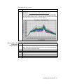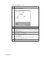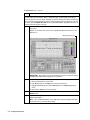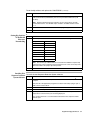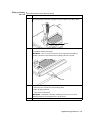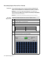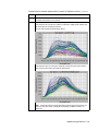
1
ABI PRISM® 7700 Sequence
Detection System and TaqMan®
Card Upgrade
Installation Manual
© Copyright 2001. All rights reserved.
For Research Use Only. Not for use in diagnostic procedures.
For limited label license information, please refer to the ABI PRISM 7700 Sequence Detection System User’s Manual, P/N 904989
ABI PRISM and its design, Applied Biosystems, Masterpiece, and MicroAmp are registered trademarks of Applera Corporation or its subsidiaries in the
U.S. and certain other countries.
ABI is a trademark of Applera Corporation or its subsidiaries in the U.S. and certain other countries.
AmpliTaq Gold and TaqMan are registered trademarks of Roche Molecular Systems, Inc.
AppleScript and Macintosh are registered trademarks of Apple Computer, Inc.
All other trademarks are the sole property of their respective owners.
Applera Corporation is committed to providing the world’s leading technology and information for life scientists. Applera Corporation consists of the
Applied Biosystems and Celera Genomics businesses.
07/2001
4316192C
Contents
1 Start Here
Overview . . . . . . . . . . . . . . . . . . . . . . . . . . . . . . . . . . . . . . . . . . . . . . . . . . . . . . . . . . . . . . . . . . 1-1
Before You Begin . . . . . . . . . . . . . . . . . . . . . . . . . . . . . . . . . . . . . . . . . . . . . . . . . . . . . . . . . . . . 1-2
Installation Schedules/Checklists for Different Installations . . . . . . . . . . . . . . . . . . . . . . . . . . . 1-3
2 Safety
Overview . . . . . . . . . . . . . . . . . . . . . . . . . . . . . . . . . . . . . . . . . . . . . . . . . . . . . . . . . . . . . . . . . . 2-1
Laboratory and Instrument Safety Requirements. . . . . . . . . . . . . . . . . . . . . . . . . . . . . . . . . . . . 2-2
Laser Safety . . . . . . . . . . . . . . . . . . . . . . . . . . . . . . . . . . . . . . . . . . . . . . . . . . . . . . . . . . . . . . . . 2-5
Laboratory Requirements . . . . . . . . . . . . . . . . . . . . . . . . . . . . . . . . . . . . . . . . . . . . . . . . . . . . . . 2-6
General Warnings . . . . . . . . . . . . . . . . . . . . . . . . . . . . . . . . . . . . . . . . . . . . . . . . . . . . . . . . . . . . 2-8
3 Setting Up and Testing the System
Overview . . . . . . . . . . . . . . . . . . . . . . . . . . . . . . . . . . . . . . . . . . . . . . . . . . . . . . . . . . . . . . . . . . 3-1
Getting Started . . . . . . . . . . . . . . . . . . . . . . . . . . . . . . . . . . . . . . . . . . . . . . . . . . . . . . . . . . . . . . 3-2
Electrical Configuration . . . . . . . . . . . . . . . . . . . . . . . . . . . . . . . . . . . . . . . . . . . . . . . . . . . . . . . 3-3
Computer and Software Setup . . . . . . . . . . . . . . . . . . . . . . . . . . . . . . . . . . . . . . . . . . . . . . . . . . 3-6
System Testing At Startup . . . . . . . . . . . . . . . . . . . . . . . . . . . . . . . . . . . . . . . . . . . . . . . . . . . . . 3-8
Thermal Cycler Tests . . . . . . . . . . . . . . . . . . . . . . . . . . . . . . . . . . . . . . . . . . . . . . . . . . . . . . . . . 3-9
Laser Alignment Test . . . . . . . . . . . . . . . . . . . . . . . . . . . . . . . . . . . . . . . . . . . . . . . . . . . . . . . . 3-10
Fluorescence and Background Checks. . . . . . . . . . . . . . . . . . . . . . . . . . . . . . . . . . . . . . . . . . . 3-11
4 Performing a Spectral Calibration
Overview . . . . . . . . . . . . . . . . . . . . . . . . . . . . . . . . . . . . . . . . . . . . . . . . . . . . . . . . . . . . . . . . . . 4-1
Spectral Calibration Overview . . . . . . . . . . . . . . . . . . . . . . . . . . . . . . . . . . . . . . . . . . . . . . . . . . 4-2
Materials . . . . . . . . . . . . . . . . . . . . . . . . . . . . . . . . . . . . . . . . . . . . . . . . . . . . . . . . . . . . . . . . . . . 4-2
Archiving Current Component Files . . . . . . . . . . . . . . . . . . . . . . . . . . . . . . . . . . . . . . . . . . . . . 4-3
Generating the Background Component File . . . . . . . . . . . . . . . . . . . . . . . . . . . . . . . . . . . . . . . 4-4
Generating a Pure Dye File . . . . . . . . . . . . . . . . . . . . . . . . . . . . . . . . . . . . . . . . . . . . . . . . . . . . 4-6
5 Verifying the Instrument
Overview . . . . . . . . . . . . . . . . . . . . . . . . . . . . . . . . . . . . . . . . . . . . . . . . . . . . . . . . . . . . . . . . . . 5-1
The ABI PRISM 7700 Instrument Verification Run . . . . . . . . . . . . . . . . . . . . . . . . . . . . . . . . . . 5-2
Preparing the ß-Actin Installation Plate . . . . . . . . . . . . . . . . . . . . . . . . . . . . . . . . . . . . . . . . . . . 5-3
Setting Up and Starting the ß-Actin Installation Run. . . . . . . . . . . . . . . . . . . . . . . . . . . . . . . . . 5-6
i
Preparing and Running the RNase P Instrument Verification Plate . . . . . . . . . . . . . . . . . . . . . 5-9
Analyzing Data . . . . . . . . . . . . . . . . . . . . . . . . . . . . . . . . . . . . . . . . . . . . . . . . . . . . . . . . . . . . 5-13
7700 Sequence Detection System Verification Calculations. . . . . . . . . . . . . . . . . . . . . . . . . . 5-15
6 TaqMan Card Upgrade Protocol
Overview . . . . . . . . . . . . . . . . . . . . . . . . . . . . . . . . . . . . . . . . . . . . . . . . . . . . . . . . . . . . . . . . . . 6-1
Section: TaqMan Card Upgrade Overview . . . . . . . . . . . . . . . . . . . . . . . . . . . . . . . . .6-2
Installation Procedure . . . . . . . . . . . . . . . . . . . . . . . . . . . . . . . . . . . . . . . . . . . . . . . . . . . . . . . . 6-3
Materials . . . . . . . . . . . . . . . . . . . . . . . . . . . . . . . . . . . . . . . . . . . . . . . . . . . . . . . . . . . . . . . . . . 6-4
Section: Performing a TaqMan Card Upgrade . . . . . . . . . . . . . . . . . . . . . . . . . . . . .6-5
Installing the Firmware and Software . . . . . . . . . . . . . . . . . . . . . . . . . . . . . . . . . . . . . . . . . . . . 6-6
Alignment Pin Replacement . . . . . . . . . . . . . . . . . . . . . . . . . . . . . . . . . . . . . . . . . . . . . . . . . . . 6-9
Setting Up the Filling Station and Vacuum Pump Assembly . . . . . . . . . . . . . . . . . . . . . . . . . 6-10
Preparing the PCR Reaction Mix and Filling the TaqMan Card . . . . . . . . . . . . . . . . . . . . . . . 6-12
Loading the Card into the 7700 Instrument. . . . . . . . . . . . . . . . . . . . . . . . . . . . . . . . . . . . . . . 6-19
Determining Exposure Time for Data Collection . . . . . . . . . . . . . . . . . . . . . . . . . . . . . . . . . . 6-22
Setting Up and Starting a TaqMan Card Run . . . . . . . . . . . . . . . . . . . . . . . . . . . . . . . . . . . . . 6-25
Section: Analyzing Card Data, Exporting Results, and Troubleshooting . . . . . . . .6-27
Analyzing the Card Data and Verifying System Performance . . . . . . . . . . . . . . . . . . . . . . . . 6-28
Exporting Results . . . . . . . . . . . . . . . . . . . . . . . . . . . . . . . . . . . . . . . . . . . . . . . . . . . . . . . . . . 6-31
TaqMan Card Verification Calculations . . . . . . . . . . . . . . . . . . . . . . . . . . . . . . . . . . . . . . . . . 6-32
Troubleshooting . . . . . . . . . . . . . . . . . . . . . . . . . . . . . . . . . . . . . . . . . . . . . . . . . . . . . . . . . . . . 6-34
7 Customer Training
Overview . . . . . . . . . . . . . . . . . . . . . . . . . . . . . . . . . . . . . . . . . . . . . . . . . . . . . . . . . . . . . . . . . . 7-1
Customer Training for the 7700 Sequence Detection System . . . . . . . . . . . . . . . . . . . . . . . . . . 7-2
Customer Training for the TaqMan Card Upgrade . . . . . . . . . . . . . . . . . . . . . . . . . . . . . . . . . . 7-3
Completing the Installation . . . . . . . . . . . . . . . . . . . . . . . . . . . . . . . . . . . . . . . . . . . . . . . . . . . . 7-4
A Abbreviations
B Material and Equipment
ABI PRISM 7700 Instrument Installation Kit. . . . . . . . . . . . . . . . . . . . . . . . . . . . . . . . . . . . . . . B-2
TaqMan Card Upgrade Kit . . . . . . . . . . . . . . . . . . . . . . . . . . . . . . . . . . . . . . . . . . . . . . . . . . . . B-4
Customer-Supplied Materials and Equipment. . . . . . . . . . . . . . . . . . . . . . . . . . . . . . . . . . . . . . B-5
C 7700 Installation Specifications
7700 Instrument Installation Specifications . . . . . . . . . . . . . . . . . . . . . . . . . . . . . . . . . . . . . . . C-2
TaqMan Card Installation Specifications. . . . . . . . . . . . . . . . . . . . . . . . . . . . . . . . . . . . . . . . . . C-3
ii
D Installation Report Checklists
Preinstallation Checklists . . . . . . . . . . . . . . . . . . . . . . . . . . . . . . . . . . . . . . . . . . . . . . . . . . . . . .D-2
Customer Training Checklists . . . . . . . . . . . . . . . . . . . . . . . . . . . . . . . . . . . . . . . . . . . . . . . . . .D-5
Laboratory Safety Checklist . . . . . . . . . . . . . . . . . . . . . . . . . . . . . . . . . . . . . . . . . . . . . . . . . . . .D-7
Installation Reports. . . . . . . . . . . . . . . . . . . . . . . . . . . . . . . . . . . . . . . . . . . . . . . . . . . . . . . . . . .D-9
E Creating a TaqMan Card Template
F Software Upgrade Install Procedure
Index
iii
Start Here
1
1
Overview
About This Chapter This chapter describes the purpose of this manual and installation schedules and
checklists for different installations.
In This Chapter This chapter contains the following topics:
Topic
See Page
Before You Begin
1-2
Installation Schedules/Checklists for Different Installations
1-3
Start Here 1-1
Before You Begin
Purpose of This The instructions presented in this manual are intended to assist a trained Applied
Manual Biosystems service engineer in the installation and performance verification of the:
♦
ABI PRISM ® 7700 Sequence Detection System
♦
TaqMan card upgrade for the ABI PRISM 7700 instrument
♦
ABI PRISM 7700 instrument and TaqMan card upgrade
♦
Upgrade of software and firmware on the ABI PRISM 7700 instrument
This manual may serve as a reference during installation.
For a thorough understanding of the instrument and the installation procedure, it is
essential to receive proper service training and refer to the ABI PRISM 7700 SDS
User’s Manual. If more detailed information pertaining to the service of the instrument
is needed, refer to the ABI PRISM 7700 Sequence Detection System Service Manual.
Installation Use the following table as a guide for chapters to reference for specific types of
Procedures installations:
If you are installing the...
Refer to...
Install Time
ABI PRISM 7700 Sequence Detection
System
Chapters 1–5, 7.
2 days
TaqMan card only
Chapters 1, 2, 4- 7.
1 day
ABI PRISM 7700 Sequence Detection
System software and the TaqMan card
upgrade
Chapters 1–7.
2.5 days
SDS software upgrade
Appendix F, “Software
Upgrade Install
Procedure.”
10 minutes
Preinstallation Before scheduling the installation, the customer should be contacted in order to review
Checklists the preinstallation checklist (see “Preinstallation Checklists” on page D-2).
Review the completed checklist before starting the installation in order to ensure that
everything needed to complete the installation is available. In some instances, the
installation can be started even though some preparations have not been made; this
decision should be made based on the experience of the service engineer and after
consulting the local service management.
1-2 Start Here
Installation Schedules/Checklists for Different Installations
Suggested The following suggested installation schedules are to be used as guidelines.
Installation Experienced engineers may modify the schedules to complete installations more
Schedules quickly.
ABI PRISM 7700 The ABI PRISM 7700 SDS installation procedure will take approximately 2 days.
Installation
Check Off Each Item As It Is Completed
Verify that all equipment, chemicals, and supplies have arrived.
Check “ABI Prism 7700 Instrument Installation Kit” on page B-2 and “TaqMan Card
Upgrade Kit” on page B-4.
Verify that all customer-supplied equipment and supplies needed to run the
chemical installation kit are readily available.
Refer to “Customer-Supplied Materials and Equipment” on page B-5 and
“Preinstallation Checklists” on page D-2.
Unpack and Setup the Power Macintosh ®.
This should include reformatting the hard drive, reloading the Macintosh computer
operating system, and installing the Sequence Detection System software.
Unpack the ABI PRISM 7700 instrument.
Check the internal electrical connections on the ABI PRISM 7700 instrument.
Test the ABI PRISM 7700 instrument software/hardware functions.
Create a new Background file and a new Spectral Components file.
Prepare and run an installation tray using the chemical installation kit and
accessories from the packing kit.
Demonstrate to the customer the instrument operation using the Sequence
Detection System software, including Sample Setup, Thermal Cycler Conditions,
and Starting Runs.
Analyze the run from the previous day and determine if it passes the installation
specifications.
The customer should do this as part of their training.
Show the customer how to display Raw Data, Standard Curves, and Amplification
Plots.
Review data analysis procedures with the customer, including setting the threshold,
reanalyzing data, and examining the Experimental Report for statistical information.
Demonstrate system maintenance procedures.
Demonstrate Macintosh computer maintenance and file backup.
Fill out and send in all software registration cards and the installation postcard that
are found with the system.
These include the cards for the Macintosh computer software.
Read the MSDSs provided by the chemical manufacturers.
Start Here 1-3
TaqMan Card The TaqMan® Human Cytokine Card Upgrade installation will take approximately one
Upgrade Installation day.
Check Off Each Item As It Is Completed
Verify that all equipment, chemicals, and supplies have arrived.
Check “ABI Prism 7700 Instrument Installation Kit” on page B-2 and “TaqMan Card
Upgrade Kit” on page B-4.
Verify that all customer-supplied equipment and supplies needed to run the
chemical installation kit are readily available.
Refer to “Customer-Supplied Materials and Equipment” on page B-5 and
“Preinstallation Checklists” on page D-2.
Create a new Background file and a new Spectral Components file.
Run an RNAse P installation tray to verify system performance.
Set up the ABI PRISM ® Card Filling station and vacuum pump assembly and verify
that the vacuum pump pulls the necessary vacuum for filling cards.
Analyze the RNAse P run and determine if it passes the installation specifications.
Install the card upgrade firmware and software.
Replace 7700 alignment pins if necessary.
Fill and run a card using human genomic DNA and Universal PCR master mix.
Before starting chemistry run, check 7700 exposure time for card data collection
and adjust if necessary.
Demonstrate to customer how to fill card and set up card run and how to determine
the proper exposure time for a run.
Analyze the run and determine if VIC dye layer passes the installation
specifications.
The customer should do this as part of their training.
Review card troubleshooting procedures: checking for/fixing vacuum leaks in filling
system, aligning card and adapters in the 7700 instrument, etc.
Fill out and send in the installation post card that is included in the installation kit.
1-4 Start Here
Safety
2
2
Overview
About This Chapter This chapter contains general safety information and guidelines for working in a
customer’s laboratory.
In This Chapter This chapter contains the following topics:
Topic
See Page
Laboratory and Instrument Safety Requirements
2-2
Laser Safety
2-5
Laboratory Requirements
2-6
General Warnings
2-8
Safety 2-1
Laboratory and Instrument Safety Requirements
Documentation User Five user attention words appear in the text of all Applied Biosystems user
Attention Words documentation. Each word implies a particular level of observation or action as
described below.
Note
Calls attention to useful information.
IMPORTANT Indicates information that is necessary for proper instrument operation.
! CAUTION Indicates a potentially hazardous situation which, if not avoided, may result in
minor or moderate injury. It may also be used to alert against unsafe practices.
! WARNING Indicates a potentially hazardous situation which, if not avoided, could result in
death or serious injury.
! DANGER Indicates an imminently hazardous situation which, if not avoided, will result in
death or serious injury. This signal word is to be limited to the most extreme situations.
Chemical Hazard ! WARNING CHEMICAL HAZARD. Some of the chemicals used with Applied Biosystems
Warning instruments and protocols are potentially hazardous and can cause injury, illness, or death.
♦
Read and understand the material safety data sheets (MSDSs) provided by the
chemical manufacturer before you store, handle, or work with any chemicals or
hazardous materials.
♦
Minimize contact with chemicals. Wear appropriate personal protective equipment
when handling chemicals (e.g., safety glasses, gloves, or protective clothing). For
additional safety guidelines, consult the MSDS.
♦
Minimize the inhalation of chemicals. Do not leave chemical containers open. Use
only with adequate ventilation (e.g., fume hood). For additional safety guidelines,
consult the MSDS.
♦
Check regularly for chemical leaks or spills. If a leak or spill occurs, follow the
manufacturer’s cleanup procedures as recommended on the MSDS.
♦
Comply with all local, state/provincial, or national laws and regulations related to
chemical storage, handling, and disposal.
Chemical Waste ! WARNING CHEMICAL WASTE HAZARD. Wastes produced by Applied Biosystems
Hazard Warning instruments are potentially hazardous and can cause injury, illness, or death.
2-2 Safety
♦
Read and understand the material safety data sheets (MSDSs) provided by the
manufacturers of the chemicals in the waste container before you store, handle,
or dispose of chemical waste.
♦
Handle chemical wastes in a fume hood.
♦
Minimize contact with chemicals. Wear appropriate personal protective equipment
when handling chemicals (e.g., safety glasses, gloves, or protective clothing). For
additional safety guidelines, consult the MSDS.
♦
Minimize the inhalation of chemicals. Do not leave chemical containers open. Use
only with adequate ventilation (e.g., fume hood). For additional safety guidelines,
consult the MSDS.
♦
After emptying the waste container, seal it with the cap provided.
♦
Dispose of the contents of the waste tray and waste bottle in accordance with
good laboratory practices and local, state/provincial, or national environmental
and health regulations.
Site Preparation and A site preparation and safety guide is a separate document sent to all customers who
Safety Guide have purchased an Applied Biosystems instrument. Refer to the guide written for your
instrument for information on site preparation, instrument safety, chemical safety, and
waste profiles.
Ordering MSDSs You can order free additional copies of MSDSs for chemicals manufactured or
distributed by Applied Biosystems using the contact information below.
To order MSDSs...
Then...
Over the Internet
a. Go to our Web site at
www.appliedbiosystems.com/techsupp
b. Click MSDSs
If you have...
Then...
The MSDS document
number or the Document
on Demand index number
Enter one of these
numbers in the appropriate
field on this page.
The product part number
Select Click Here, then
enter the part number or
keyword(s) in the field on
this page.
Keyword(s)
c. You can open and download a PDF (using Adobe®
Acrobat® Reader™) of the document by selecting it, or
you can choose to have the document sent to you by fax
or email.
By automated telephone
service
Use “To Obtain Documents on Demand” under “Technical
Support.”
By telephone in the United
States
Dial 1-800-327-3002, then press 1.
By telephone from Canada
By telephone from any other
country
To order in...
Dial 1-800-668-6913 and...
English
Press 1, then 2, then 1 again
French
Press 2, then 2, then 1
See the specific region under “To Contact Technical Support
by Telephone or Fax” under “Technical Support.”
For chemicals not manufactured or distributed by Applied Biosystems, call the
chemical manufacturer.
Instrument Safety Safety labels are located on the instrument. Each safety label has three parts:
Labels ♦ A signal word panel, which implies a particular level of observation or action (e.g.,
CAUTION or WARNING). If a safety label encompasses multiple hazards, the
signal word corresponding to the greatest hazard is used.
♦
A message panel, which explains the hazard and any user action required.
Safety 2-3
♦
A safety alert symbol, which indicates a potential personal safety hazard. See the
ABI PRISM® 7700 Site Preparation and Safety Guide for an explanation of all the
safety alert symbols provided in several languages.
About Waste As the generator of potentially hazardous waste, it is your responsibility to perform the
Disposal actions listed below.
♦
Characterize (by analysis if necessary) the waste generated by the particular
applications, reagents, and substrates used in your laboratory.
♦
Ensure the health and safety of all personnel in your laboratory.
♦
Ensure that the instrument waste is stored, transferred, transported, and disposed
of according to all local, state/provincial, or national regulations.
Note Radioactive or biohazardous materials may require special handling, and disposal
limitations may apply.
Moving and Lifting ! CAUTION PHYSICAL INJURY HAZARD. Improper lifting can cause painful and
the Instrument sometimes permanent back injury.
Use proper lifting techniques when lifting or moving the instrument. Safety training for
proper lifting techniques is recommended.
Do not attempt to lift or move the instrument without the assistance of others.
Depending on the weight of the instrument, this action may require two or more
people.
Before Operating the Ensure that everyone involved with the operation of the instrument has:
Instrument ♦ Received instruction in general safety practices for laboratories
♦
Received instruction in specific safety practices for the instrument
♦
Read and understood all related MSDSs
! CAUTION Avoid using this instrument in a manner not specified by Applied Biosystems.
Although the instrument has been designed to protect the user, this protection can be impaired
if the instrument is used improperly.
2-4 Safety
Laser Safety
Contains Argon Gas In addition to the standard hazards in electromechanical instrumentation, the
Laser ABI PRISM ® 7700 Sequence Detector contains an argon ion gas laser that emits up to
10 mW of electromagnetic radiation, principally at 488.0 nm. The instrument has been
designed to comply with Title 21, U.S. Government DHEW/BRH Performance
Standards, Chapter 1, Subchapter J, Section 1040, as applicable. This product falls
into Class I category when all interlocks are in place.
Safety Features The following safety features have been incorporated in the ABI PRISM 7700
Incorporated instrument:
♦
The cabinet is designed to prevent access to collateral laser radiation exceeding
the accessible emission limits listed in Performance Standards for Laser Products,
21 CFR 1040.10.
♦
The heated cover assembly, when it is not forward and locked down, activates
interlock switches that cause the laser light path to be blocked.
♦
Safety labels for Class I Standards have been affixed to the instrument to warn of
the danger from laser radiation.
♦
These interlocks and labels must not be removed or defeated by customers. The
interlocks and labels ensure compliance with the above mentioned performance
standards of the U.S. Code of Federal Regulations. Only authorized service
personnel are allowed to defeat these interlocks during service, maintenance, or
installation of the instrument.
WARNING ! WARNING ! VISION HAZARD: LASER SOURCE. When the laser beam is exposed,
as it will be during some of the installation procedures, it is Class IIIb, which is extremely
hazardous. Direct or reflected laser beam exposure at 10mW for 0.1 second can burn the
eye’s retina, leaving a permanent blind spot.
Safety Precautions When performing procedures that require the interlock to be defeated, you must follow
When Interlock Is these safety precautions:
Defeated ♦ Post warning signs (P/N T-5350) on the laboratory door and in the work area to
warn of the danger from laser radiation.
♦
Make sure the laser power is at its minimum setting to decrease the hazard from
the light intensity.
♦
Never look directly into the laser beam or the laser head opening.
♦
Always use the laser alignment tool when checking the laser light path during
service procedures to prevent the reflection of laser light into the room.
♦
Remove all rings, watches, jewelry, and metal frame eyeglasses that might reflect
the laser beam into someone’s eyes.
♦
Wear laser safety goggles (P/N 100355) specially designed to protect eyes
against laser light.
Safety 2-5
Laboratory Requirements
Preinstallation Before scheduling the installation, the customer should be contacted in order to go
Checklist through the preinstallation checklist (see page D-2). Review the completed checklist
before starting the installation in order to ensure that everything needed to complete
the installation is available. In some instances, the installation can be started even
though some preparations have not been made; this decision should be made based
on the experience of the service engineer and after consulting the local service
management.
Laboratory Space ABI PRISM 7700 Instrument Dimensions
Requirements
Width
Depth
Height
Weight
94 cm
72.5 cm
61 cm
130 kg
(37 in.)
(28.5 in.)
(24 in.)
(286 lb.)
IMPORTANT A minimum of 15 cm (6.0 in.) clearance at the rear of the instrument and 69 cm
(27 in) above the instrument is necessary to provide adequate ventilation and service access.
The Macintosh ® computer should be on the same table as the ABI PRISM 7700
instrument. If this is impractical, the equipment should not be located further than 1.8
m (6 ft.) from the instrument. Both the ABI PRISM 7700 instrument and the Macintosh
computer fit on a 1.8 meter (6 ft.) wide table or bench.
Environmental The laboratory temperature should be maintained between 15 °C (59 °F) and 30 °C
Conditions and (85 °F). The relative humidity in the laboratory should be no greater than 80%. The
Requirements unit should not be placed near heaters or cooling ducts.
The thermal output of the instrument when it is operating under normal conditions is
8800 Btu/h (~2600 W).
This unit is for indoor use only and for altitudes not exceeding 2,000 meters.
The installation category (transient overvoltage category) for this instrument is II and it
is classified as portable equipment. The instrument has a pollution degree rating of 2
and may be installed in an environment that has non-conductive pollutants only.
Electrical The electrical receptacle should have a dedicated electrical line with a circuit breaker
Requirements rated at 30A (with a power rating of 6.0 kVA). There should also be an isolated
electrical ground between the instrument and the building main electrical service. The
electrical receptacle must be located within 3 m (10 ft.) of the instrument rear panel.
The following table specifies the electrical operating range for various locations:
2-6 Safety
Voltage (AC)
Frequency (Hz)
Location
200 +/- 10%
50/60 +/- 1%
Japan
208 +/- 10%
50/60 +/- 1%
USA/Canada
220 +/- 10%
50/60 +/- 1%
pre-1992 Europe
230 +/- 10%
50/60 +/- 1%
EC
240 +/- 10%
50/60 +/- 1%
Australia and pre-1992 UK
CAUTION Connecting the instrument to the wrong voltage source can damage the
instrument. Do not assume that the laboratory’s voltage supply is correct. Always
measure the voltage at the wall receptacle before configuring the power supplies,
connecting the power cord, and turning the instrument on.
In the U.S.A., Canada, and Japan, the instrument is supplied with a detachable
electrical cord equipped with a NEMA L6-30P 30A/250V twistlock plug. The electrical
receptacle which accepts this plug is the NEMA L6-30R twistlock receptacle (30A/250
V). This receptacle is not supplied by Applied Biosystems. It is available from Hubbell,
Inc. (part number 2620A).
In Europe and Australia, the instrument is supplied with a detachable electrical cord
equipped with a IEC-309 30A/240V plug. The electrical receptacle which accepts this
plug is available in two types, panel mount (part number 58074) or surface mount (part
number 58004) These receptacles are not supplied by Applied Biosystems. They are
available from any LEGRAND distributor.
Voltage Quality Line voltage must be within 10% of the nominal value. High or low voltages may have
adverse effects on the electronic components of the ABI PRISM 7700 instrument.
A dedicated line and isolated ground between the instrument and building main
electrical service are necessary to help prevent such “voltage spikes”. If the laboratory
environment contains devices which are electrically “noisy”, or if you are in an area
with frequent electrical storms, a line conditioner may enhance the system’s reliability.
A 5 kVA capacity is generally recommended to help ensure the proper operation of the
instrument.
Certain types of electrical noise are greatly exaggerated by poor or improper electrical
ground connections. To prevent these problems, it is very important to have a
dedicated line and isolated ground between the instrument and building main
electrical service.
Safety 2-7
General Warnings
Chemical Hazard ! WARNING ! CHEMICAL HAZARD. Some of the chemicals used with Applied
Warning Biosystems instruments are potentially hazardous and can cause injury, illness or death.
x
Read and understand the material safety data sheets (MSDSs) provided by the
chemical manufacturer before you store, handle, or work with any chemicals or
hazardous materials.
x
Minimize contact with and inhalation of chemicals. Wear appropriate personal
protective equipment when handling chemicals (e.g., safety glasses, gloves, or
clothing). For additional safety guidelines consult the MSDS.
x
Do not leave chemical containers open. Use only with adequate ventilation.
x
Check regularly for chemical leaks or spills. If a leak or spill occurs, follow the
manufacturer’s cleanup procedures as recommended on the MSDS.
x
Comply with all local, state/provincial, or national laws and regulations related to
chemical storage, handling, and disposal.
Chemical Waste ! WARNING ! CHEMICAL WASTE HAZARD. Wastes produced by Applied
Hazard Warning Biosystems instruments are potentially hazardous and can cause injury, illness, or
death.
x
Read and understand the material safety data sheets (MSDSs) provided by the
manufacturers of the chemicals in the waste container before you store, handle, or
dispose of chemical waste.
x
Handle chemical wastes in a fume hood.
x
Minimize contact with and inhalation of chemical waste. Wear appropriate personal
protective equipment when handling chemicals (e.g., safety glasses, gloves, or
clothing).
x
After emptying the waste container, seal it with the cap provided.
x
Dispose of the contents of the waste tray and waste bottle in accordance with good
laboratory practices and local, state/provincial, or national environmental and health
regulations.
Electrical Shock ! WARNING ! ELECTRICAL SHOCK HAZARD. Severe electrical shock, which could
Hazard cause physical injury or death, can result from working on an instrument when the high
voltage power supply is operating. To avoid electrical shock, disconnect the power
supply to the instrument, unplug the power cord, and wait at least 1 minute before
working on the instrument.
2-8 Safety
Setting Up and Testing
the System
3
3
Overview
About This Chapter This chapter describes the instrument electrical configuration, and the setup of the
computer and software. It also contains procedures that test: the electrical system, the
thermal cycler, the laser alignment, and the fluorescence and background.
In This Chapter This chapter contains the following topics:
Topic
See Page
Getting Started
3-2
Electrical Configuration
3-3
Computer and Software Setup
3-6
System Testing At Startup
3-8
Thermal Cycler Tests
3-9
Laser Alignment Test
3-10
Fluorescence and Background Checks
3-11
Setting Up and Testing the System 3-1
Getting Started
Checking To make sure equipment and supplies are ready for installation and system testing:
Equipment
1
Verify that the safety and space requirements have been met per the ABI PRISM
7700 Site Preparation and Safety Guide to ensure there is access to the instrument
on all sides.
2
Verify that all equipment, chemicals, and supplies have arrived.
3
Verify that all customer-supplied equipment and supplies needed to run the
chemical installation kit are readily available.
Refer to the preinstallation checklist in “Preinstallation Checklists” on page D-2.
4
Unpack and setup the Power Macintosh ® computer.
This should include reformatting the hard drive, reloading the Macintosh ® computer
operating system, and installing the Sequence Detection System software.
5
3-2 Setting Up and Testing the System
Unpack the ABI PRISM ® Sequence Detector.
Electrical Configuration
Checking the Inspect the electrical receptacle where the instrument is to be plugged in, to ensure
Electrical Receptacle that it matches the power cord plug. In the USA, Canada, and Japan, the receptacle
should be a NEMA L6-30R (rated at 30A/250V). In Europe and Australia, the
receptacle should accept an IEC-309 30A/250V plug. Use of receptacles other than
these may void the instrument’s safety certification and should not be used.
CAUTION Always check the laboratory voltage at the wall receptacle with a voltmeter
before configuring the instrument; incorrect voltage can lead to instrument damage.
Plugging the To connect the instrument to the power source:
Instrument In for
Step
Action
the First Time
1
Use a DVM to check voltage at the electrical receptacle.
2
After confirming the AC voltage, plug the power cord into the back of the instrument
and push the instrument’s electrical breaker down to the OFF position.
3
Plug the power cord into the wall receptacle.
Configuring the Before powering up the instrument, check and configure electrical connections to
Internal Electrical ensure proper instrument operation.
Connections To configure the internal electrical connections:
Step
Action
1
Open the main cover on the instrument (secured by four screws).
2
Inspect all electrical harnesses, especially those connected to the main CPU PCB,
to ensure that the connections are secure.
3
Locate the instrument voltage configuration plug in the packing kit, and check that it
is the proper plug by comparing it to the illustration in “7700 Instrument Voltage
Configuration Plugs” on page 3-4.
4
Inspect the front of the Laser Power Supply and set the voltage configuration switch
to the setting that corresponds to the laboratory electrical supply.
Use this setting...
For these areas...
LOW
200–208 Vac
HIGH
220–240 Vac
CAUTION Always check the laboratory voltage at the wall receptacle with a
voltmeter before configuring the instrument; incorrect voltage can lead to
instrument damage.
Setting Up and Testing the System 3-3
To configure the internal electrical connections:
Step
(continued)
Action
5
The thermal cycler operates on 230 Vac (supplied from the Vac Distribution
Assembly), but it must be configured for the proper frequency (either 50 or 60 Hz).
Insert a properly configured 36-pin voltage select plug into J-13 on the AC-Control
PCB in the 9600. The following table lists the plug and the pins that are connected:
Note
The plug has five jumpers with each wire connecting two pins.
This plug...
Has these pins jumpered...
230 V/50 Hz plug
2-5, 9-17, 28-34, 31-36, and 33-35 jumpered
230 V/60 Hz plug
2-5, 9-16, 28-34, 31-36, and 33-35 jumpered
For configuration information, see “7700 Instrument Voltage Configuration Plugs,”
below.
CAUTION Damage to the 9600 may occur if the wrong voltage
configuration plug is inserted into J-13. Always check the wiring of the 9600
voltage configuration plug before installing it in the instrument.
6
The thermal cycler must also be configured for the proper electrical frequency
(either 50 or 60 Hz.).
See “Configuring the Thermal Cycler Frequency for 50 hertz Areas” on page 3-5.
7700 Instrument CAUTION If the ABI PRISM 7700 instrument is not configured properly, the voltage
Voltage supplied to the thermal cycler may be incorrect, resulting in electronics or firmware
Configuration Plugs damage.
Listed from left to right, the voltage select plugs are for 200, 208, 220, and 240 Vac.
1
4
7
1
4
7
1
4
7
1
4
7
2
5
8
2
5
8
2
5
8
2
5
8
3
6
9
3
6
9
3
6
9
3
6
9
ABI PRISM 7700 Voltage Configuration Plugs
Pins
Description...
#1 and #3
are oriented to the left and have a flat side.
Jumpered pins (shown in shaded colors)
Are for this voltage...
2-5, 4-9, and 6,7
200 V
2-5,3-9, and 6,7
208 V
2-5, 1-9, 6-7
220 V
5-9 and 6-7
230/240 V.
3-4 Setting Up and Testing the System
Configuring the
Thermal Cycler
Frequency for 50
hertz Areas
After the thermal cycler voltage-frequency configuration plug has been installed and
the instrument is plugged in, the thermal cycler firmware must also be configured if the
instrument is to be run in 50 hertz areas.
To configure the 7700 instrument thermal cycler’s electrical frequency:
Step
1
Action
Start the thermal cycler.
a. Plug a 9600 keyboard assembly into the thermal cycler CPU PCB.
b. While holding the keyboard ENTER key, turn the 7700 instrument on.
The power switch is located at the lower left front of the instrument. The instrument
circuit breakers are located at the back near the power cord receptacle.
The 9600 display will appear when the key is released.
2
Calibrate the thermal cycler for 50 hertz areas.
a. After the 9600 display comes on, press MORE 999 to access the 9600 service
diagnostics.
b. Press the OPTION key twice to move the cursor to the CALIB selection and then
press ENTER.
c. After the first calibration test appears, press STEP to go to Calibration Test #2.
d. Press ENTER to view the present voltage and frequency configuration.
e. Press the STEP or OPTION keys until the correct configuration is reached.
f. Press STOP 5 times to reset the thermal cycler.
g. Turn off the instrument and remove the 9600 keyboard when you are finished.
Setting Up and Testing the System 3-5
Computer and Software Setup
System Setup Cable connections of the ABI PRISM 7700 Sequence Detection System.
Setting Up the
Computer
Step
1
Action
Follow the basic setup procedure in the Macintosh computer documentation
shipped with the computer.
CAUTION Always check the voltage configuration at the back of the
computer to ensure that it matches the site voltage. Failure to properly set the
voltage switch can cause damage to the computer.
2
Connect the computer to the 7700 instrument with the 6 ft. cable found in the
instrument packing kit.
Attach the cable to the modem port at the back of the computer, and then to the
computer port on the back of the instrument.
3
Turn on the monitor.
4
Turn on the computer by pressing the Power key on the keyboard. The power key
is marked with a triangle.
5
Install the Macintosh Computer Operating System:
a. Insert the Apple CD that contains the operating system.
b. Restart the computer while pressing the C key.
c. Reinitialize the hard drive (see the Disk Tools folder).
d. Reload the Macintosh computer operating system: “INSTALL O.S.”
e. Restart the computer.
3-6 Setting Up and Testing the System
Installation of the Perform the following steps to load the SDS application on the hard disk. This
Software procedure should also be used if the application is corrupted and must be reloaded.
Step
Action
1
Insert the ABI PRISM 7700 CD-ROM into the CD-ROM drive.
2
Use the Installer program to load the application.
After installation is complete, restart the computer.
Note Always run Norton Utilities from the CD. Do not install Norton Disk Utilities
or Norton Disk Doctor on the hard drive.
3
Microsoft Excel is shipped with the 7700 instrument, but it is not used for all service
procedures.
Install Excel only if performing a TaqMan card upgrade, or if the customer requests
it.
4
Open the Utilities folder and drag the Techtool ® application to the hard drive.
Techtool should be used once a week to rebuild the desktop.
5
Go to the Energy Save Control Panel and set to NEVER for all settings.
6
Go to the Memory Control Panel and turn Virtual Memory off, and ensure that there
is at least 32 MB of built-in RAM.
7
Open the Extensions Manager Control Panel, and check that the PowerPC Interrupt
extension is turned on (restart the computer if necessary).
Note The Power PC Interrupt extension is not needed with Macintosh OS 7.6 and
newer.
8
Rebuild the Macintosh computer desktop when the installation is complete.
Also, rebuild the Macintosh computer desktop as needed in the event that
unexpected computer crashes cause operational problems.
9
Restart the computer before starting any run for service purposes.
Setting Up and Testing the System 3-7
System Testing At Startup
Power-Up Tests Ensuring that the electronics and electrical system of the 7700 instrument are
functioning properly is important. The following procedure can be used to check the
system electronics.
To perform the 7700 instrument Power-up Test:
Step
Action
1
Turn on the instrument.
2
Look at the three (3) LEDs on the front panel near the heated cover:
♦ If the READY LED is lit, the instrument has booted up properly.
♦ The COMM LED will blink when the 7700 instrument is communicating with the
computer.
3
Open the instrument main cover, and check that the 683324 PCB LEDs are
“marching”, which is the ready state. (This confirms that the 7700 instrument has
booted-up properly.)
4
After the 7700 instrument has booted-up, launch the Sequence Detection System
(SDS) software on the computer and open a background plate.
Note When the SDS is launched a dialog boxes appears with the message,
“Could not open document because needed Pure Spectra are missing (FAM,
TAMRA). New Pure Spectra must be extracted.” Click OK.
To open a background plate:
a. From the File menu, select New Plate.
b. Select background plate and click OK.
Note The following steps require an open plate document, although you will not
actually perform a run.
5
Run Instrument Verification.
a. Click the Show Analysis button.
b. From the Instrument menu, select Diagnostics, and 7700 instrument Verification
from the submenu. The Instrument Tests dialog box appears.
c. Click the Run Tests button.
3-8 Setting Up and Testing the System
If...
Then...
the test passes
proceed to the “Thermal Cycler Tests”
on page 3-9.
any test fails
ensure that the ABI PRISM 7700
instrument booted from the proper
firmware.
Thermal Cycler Tests
System Performance Note Thermal Cycler tests, which are run with the use of a 9600 Service Keyboard Assembly,
Test ensure that the internal ABI PRISM 7700 thermal cycler operation is not being affected by the
7700 CPU. The 9600 Service Keyboard Assembly must be used because the 7700 instrument
contains a modified 9600 that does not have a keyboard and display.
Step
Action
1
Make sure that the instrument power is off.
2
Plug a 9600 keyboard assembly into the thermal cycler CPU PCB.
3
a. While holding the keyboard ENTER key down, turn the power switch on.
The power switch is located at the lower left front of the instrument.
b. Release the ENTER key after a few seconds.
4
After the 9600 display appears, let the 7700 thermal cycler warm up for at least 5
minutes before running any tests.
5
Press the Option key to step to UTIL, and then to the DIAG menu to access the user
diagnostics.
6
Select the System Performance test, and then click OK.
7
Use the System Performance test result to determine the next step:
If...
Then...
the System Performance test passes
proceed to the “Laser Alignment Test”
on page 3-10.
the System Performance test fails
proceed to step 8.
Note System Performance test results can be unreliable on some newer thermal
cycler compressors, which are more powerful than older compressors. If a failure is
encountered, run the Chiller test and Heater test before repairing any thermal cycler.
8
Run the Chiller test and the Heater test.
Note The Chiller test and Heater test can also fail due to the new compressors
and do not necessarily mean that the thermal cycler has a problem. Run the
chemical installation kit to verify that there is, in fact, a problem with the thermal
cycler before taking corrective action.
9
If the results of the chemical installation run indicate that the thermal cycler has a
problem, then take the following action:
a. Unless a hard failure is observed, perform a temperature verification run before
replacing components. See Chapter 5, “Verifying the Instrument.”
b. Determine what the problem is by inspecting the thermal cycler profile for the
verification run from either the Raw Data view or Multicomponent view.
10
Additional 9600 Service Tests can be run on the 7700 instrument using the 9600
Service Diagnostics.
Note The 9600 Service Diagnostic Install Test will fail in many cases, because the
heated cover is different in the 7700 instrument. If the test fails, press MORE 999
to bypass the test and automatically set the install flag.
Setting Up and Testing the System 3-9
Laser Alignment Test
About Checking the The ABI PRISM 7700 instrument’s laser and optics were aligned during the
Alignment manufacturing process and probably do not need to be realigned. However, the
alignment should be checked to ensure that the instrument was not damaged during
shipment.
Use the following two procedures to check the alignment of the laser. The first
procedure prepares the instrument for the alignment check. The second procedure
checks the alignment of the laser.
Preparing the 7700
Instrument for
Alignment
Step
Action
1
Make sure the instrument is off.
2
Remove any articles from the top of the 7700 instrument and raise the cover.
3
Remove the beam path cover.
4
Attach the laser alignment tool to the front of the optical cube.
5
Post a laser warning sign and put on laser safety goggles.
! WARNING ! VISION HAZARD: LASER SOURCE. When the laser beam
is exposed, it is Class IIIb, which is extremely hazardous. Direct or reflected
laser beam exposure at 10mW for 0.1 second can burn the eye’s retina,
leaving a permanent blind spot.Eye Hazard.
6
By-pass the laser interlock switches by either
♦ Pulling the heated cover forward
or
♦ Using the Laser Interlock Defeat Switch.
Checking Alignment
7
Turn the instrument on.
1
Start the Sequence Detection System software on the Power Macintosh ®
computer.
2
Go to the Functions Test menu.
3
Open the Shutters, and check the position of the laser beam on the front and back
targets.
IMPORTANT Do not change the laser alignment if the laser beam is not centered
exactly on the middle of the laser targets. The final laser alignment is never verified
or adjusted using the laser alignment tool.
4
Close the shutters, remove the laser alignment tool, and put a Fluorescent Test tray
in the sample block, and close the heated cover.
5
Open the shutters and read (“poll”) the CCD at various MUX positions.
Signal should be seen on all wells that contain a fluorescent sample. To check the
laser alignment, use the 7700 Service Diagnostics Application Plate Read Tests.
6
When the alignment has been checked, replace the optical path cover, and close
the 7700 instrument’s main cover.
Note
3-10 Setting Up and Testing the System
If the laser requires alignment, refer to Service Bulletin #12.
Fluorescence and Background Checks
Fluorescent Tests
(Signal Throughput)
Test
Description
Fluorescent Test tray
(P/N T-6222)
Signal throughput can be checked using a Fluorescent Test tray.
The example in the figure below was obtained by running the T-6222 at 25 °C for 1 minute
(open a background plate to collect data).
Note Signal heights of the fibers vary depending on the well position, the specific 7700
instrument being used, and the temperature of the test tray.
Fluorescent Tests
(Red Fluorescent
Source)
Signal throughput results can be obtained by scanning any Fluorescent Test tray for one
minute at 25 °C. Use a background plate document to collect data.
The figure below shows that the results vary depending on the type of tray being scanned.
IMPORTANT Blue test trays or paper can be used to confirm signal throughput, but do not
use them to confirm laser alignment.
Setting Up and Testing the System 3-11
Blackboard Tests The Blackboard test checks the background signal of the system (see the figure
(System Noise) below). Use a background plate document in the Sequence Detection System
software to scan a Blackboard for one minute at 25 °C. This will provide a good
indication of the background signal.
Note The maximum height of the highest peak should be less than 1200 fluorescent units. If
the system noise results are poor, refer to the ABI PRISM 7700 SEQUENCE DETECTION SYSTEM
SERVICE MANUAL for troubleshooting.
Note Signal heights vary depending on the well position, the specific ABI PRISM 7700
instrument being used, and the temperature of the test tray. Results obtained from using a
blackboard do not take into account background signal from the sample block or real PCR
samples.
3-12 Setting Up and Testing the System
Performing a Spectral
Calibration
4
4
Overview
About This Chapter This chapter describes how to archive the current component files, generate a
Background Component file, and generate a Pure Dye file.
In This Chapter This chapter contains the following topics:
Topic
See Page
Spectral Calibration Overview
4-2
Archiving Current Component Files
4-3
Materials
4-2
Generating the Background Component File
4-4
Generating a Pure Dye File
4-6
Performing a Spectral Calibration 4-1
Spectral Calibration Overview
Spectral Calibration The Spectral Calibration files are used by the ABI PRISM ® Sequence Detection
Files System software for data analysis.
When a spectral calibration is performed, two files are created:
♦
Background Component
♦
Pure Dye
These files are stored in a folder called Spectra Components, which is automatically
created when the ABI PRISM 7700 software is launched for the first time.
The Spectra Components folder is in the following location on the hard drive:
System Folder > Preferences > SDS
Spectral Calibration To perform a spectral calibration:
Process ♦ Archive or delete the current Spectra Components folder (if one already exists)
♦
Generate a Background Component file
♦
Generate a Pure Dye file
Materials
Materials Required Materials Required To Perform a Spectral Calibration
Materials
Source
SDS Spectral Calibration Kit
Applied Biosystems
(P/N 4305822)
MicroAmp ® Optical 96-Well Reaction Plate/Optical Caps
Applied Biosystems
(P/N 403012)
Gloves, disposable, powder-free
MLS
Pipettors, positive-displacement or air-displacement
MLS
Pipette tips, aerosol resistant
MLS
Water, RNase-free, distilled, deionized
MLS
4-2 Performing a Spectral Calibration
Archiving Current Component Files
Archiving To archive an existing Spectral Components folder:
Step
Action
1
Make sure that the SDS software is not running.
2
Navigate to the Spectra Components folder:
System Folder > Preferences > SDS > Spectra Components
3
Click on the Spectra Components icon text and enter a new name for the folder.
Performing a Spectral Calibration 4-3
Generating the Background Component File
Preparing
Instrument and
Background Tray
Step
Action
1
Turn on the ABI PRISM 7700 instrument and allow it to warm up for at least 30
minutes before starting the first run.
2
Prepare the background tray.
a. Pipette 50µL water into each well of a 96-well optical tray.
b. Cover wells with optical caps.
c. Make sure there are no bubbles in the wells.
Run the Background
Tray
Step
1
Action
Launch the SDS software.
Note A dialog box will appear with the message “Could not open document
because needed Pure Spectra are missing (FAM, TAMRA). New Pure Spectra must
be extracted.” Click OK and proceed.
2
Open a new background plate.
a. From the File menu, choose New Plate...
b. Select Background from the Plate Type pop-up menu.
c. Click OK.
3
Place the tray in the sample block.
4
Toggle to the Analysis View.
5
Click the Run button.
Analyze the Run To analyze the run:
Step
Action
1
Make sure the Analysis View is showing.
2
Highlight all 96 wells.
3
From the Analysis menu, select Raw Spectra.
4-4 Performing a Spectral Calibration
To analyze the run:
Step
4
(continued)
Action
Verify that all 96 curves are of similar shape and acceptable value.
IMPORTANT What is the spec? (≤ 1200 according to Jake F.)
The background for all 96 wells should be similar in shape or the instrument may
not analyze data properly. The fluorescent intensity of the background must be no
more than 1200 for all wells. If there is a problem with these results, refer to the ABI
PRISM 7700 Sequence Detection System Service Manual.
Extract and Save the
Background
Component Data
Step
1
Action
From the Instrument menu, select Calibrate > Extract Background Component.
Note At this point, the Background Component file is generated and automatically
saved to the Spectra Components folder.
2
To save the background plate document, select Save As...from the File menu.
3
Type a descriptive name for the file.
4
Click Save.
5
From the File menu, select Close to close the document.
6
Quit the SDS software.
Performing a Spectral Calibration 4-5
Generating a Pure Dye File
Preparing a Pure Prepare a pure dye tray using the SDS Spectral Calibration Kit (P/N 4305822) that is
Dye Tray shipped with the chemical installation kit.
Step
Action
1
Pipette 50 µL of each of the seven dye standards into 4 separate wells. The result
will be 28 wells containing 50 µL each. Refer to the Plate Document Setup diagram
(page 4-6, step 5) for placement suggestion.
2
Cap the tray and make sure there are no bubbles in the wells.
3
Place the tray into the sample block.
Note
Do not dilute the dye solutions.
Preparing a Pure To prepare a Pure Spectra plate document:
Spectra Plate
Step
Action
Document
1
Launch the Sequence Detection System software.
Note A dialog box appears with the message “Could not open document because
needed Pure Spectra are missing (FAM, TAMRA). New Pure Spectra must be
extracted.” Click OK and proceed.
2
Open a new Pure Spectra plate.
a. From the File menu, choose New Plate.
b. Select Pure Spectra from the Plate Type pop-up menu.
c. Click OK.
3
Open the Sample Type pop-up menu and verify that all seven of the following dyes
are listed:
FAM, JOE, ROX, SYBR, TAMRA, TET, VIC
Note If all dyes are present, skip to “Assigning Dye Standards To the Plate
Document” on page 4-7. If any of the dyes are missing, proceed to the next step.
4
To add dyes to the list, select Sample Type Setup... from the Sample Type pop-up
menu. The following dialog box appears:
5
Click Add. A new row appears at the bottom of the dye list.
4-6 Performing a Spectral Calibration
To prepare a Pure Spectra plate document:
Step
6
(continued)
Action
Click the acronym text field, and enter a name for the new dye that is no more than
5 characters long (i.e., VIC or SYBR).
Acronym text field
7
Click the name text field and enter Pure Dye.
Name text field
8
Click the color field.
Color field
The color palette dialog box appears.
9
Select a color for the new dye and click OK. The color field for the new dye fills with
the new color.
Note The color field must be changed, because the default color is gray, which is
the same as the background.
For more information on selecting a dye color, refer to the ABI PRISM 7700
Sequence Detection Systems User’s Manual.
10
Repeat step 5–9 to add other dyes to the list. Click OK when finished.
Assigning Dye To assign dye standards to the plate document:
Standards To the
Step
Action
Plate Document
1
From the Setup menu, select Sample Type Palette.
The Sample Type Palette dialog box appears:
Performing a Spectral Calibration 4-7
To assign dye standards to the plate document:
Step
(continued)
Action
2
Select the four wells from the plate document that correspond to the wells on the
MicroAmp ® Optical 96-Well Reaction Plate containing the FAM standard.
3
Click the FAM checkbox in the palette dialog box to label the wells.
Click Update from the palette box. The Sequence Detection System software
designates the selected row with the FAM dye.
4-8 Performing a Spectral Calibration
To assign dye standards to the plate document:
Step
4
(continued)
Action
Repeat steps 1–3 for each additional dye standard (JOE, ROX, SYBR Green,
TAMRA, TET, and VIC) until your plate document resembles the figure below.
Running the To run the samples and create the Pure Dye file:
Samples and
Step
Action
Creating the Pure
1
Click the Show Analysis button and click the Run button.
Dye File
2
Extract pure dye.
a. Highlight the first set of four wells that contain the FAM dyes.
b. Select Calibrate from the Instrument menu, and select Extract Pure Dye from the
submenu.
3
When the spectra for the wells are displayed, inspect the quality of the four curves.
The spectra of the four wells must be smooth and similar in shape, or the instrument
will not analyze data correctly.
Note
Contaminated wells may produce spectra that deviate from average peaks.
If a spectrum is unacceptable, move it to the discard box as described in “Removing
an Outlier Spectrum From the Averaged Box” on page 4-10.
IMPORTANT You may remove only one of the four spectra from each dye set.
4
Repeat steps 2–3 for the other six dyes.
When finished, the Pure Dye file is automatically saved in the Spectra Components
folder.
5
Save the Pure Dye plate document.
a. From the File menu, select Save As. A dialog box appears.
b. Enter Pure Dye in the Save this document as text box, and click Save.
Performing a Spectral Calibration 4-9
To run the samples and create the Pure Dye file:
Step
6
(continued)
Action
Quit the SDS software when finished.
A new Spectra Components folder is now in the SDS Preferences folder.
Note
Removing an Outlier
Spectrum From the
Averaged Box
Step
The Pure Dye file should be replaced every 60 days to six months.
Action
1
Click the outlier spectrum in the Averaged box.
2
Click the
button to move the spectrum to the discard box.
You may remove only one of the four dyes from any particular set.
Note Discarding a spectrum does not remove it from the graph, but the average is
automatically recalculated.
Pure Dye Spectra Pure Dye Spectra and Peak Wavelength
Dyes
Peak Wavelength
FAM
~520 nm
JOE
~550 nm
ROX
~610 nm
SYBR Green
~520 nm
TAMRA
~580 nm
TET
~540 nm
VIC
~550 nm
4-10 Performing a Spectral Calibration
Wavelength Axis The wavelength axis should not be used as an exact measure of wavelength but is
Purpose intended as a guide to where an individual spectrum should appear.
When the ABI PRISM 7700 instrument is spectrally calibrated, the wavelength
positions of different spectral emissions do not change. The spectrograph and CCD
camera are bolted in place, and the pixel positions of the CCD camera cannot be
changed by software commands.
Performing a Spectral Calibration 4-11
Verifying the Instrument5
5
Overview
About This Chapter This chapter describes how to prepare a ß-actin installation plate, set up and start the
ß-actin installation run, and prepare and run the RNase P installation plate. It also
includes how to analyze the data and verification calculations.
In This Chapter This chapter contains the following topics:
Topic
See Page
The ABI Prism 7700 Instrument Verification Run
5-2
Preparing the ß-Actin Installation Plate
5-3
Setting Up and Starting the ß-Actin Installation Run
5-6
Preparing and Running the RNase P Instrument Verification Plate
5-9
Analyzing Data
5-13
7700 Sequence Detection System Verification Calculations
5-15
Verifying the Instrument 5-1
The ABI PRISM 7700 Instrument Verification Run
Chemical There are two chemical installation kits available for use in verification of the
Installation Kits ABI PRISM ® 7700 Sequence Detector. Either one may be used. The following tables
Available list the steps to completing each type of verification run:
♦
ß-Actin
Method
♦
Preparing the ß-Actin Installation Plate
5-3
Setting Up and Starting the ß-Actin Installation Run
5-6
Analyzing Data
5-13
RNase P
Method
5-2 Verifying the Instrument
See Page
See Page
Preparing and Running the RNase P Instrument Verification
Plate
5-9
Analyzing Data
5-13
Preparing the ß-Actin Installation Plate
Chemistry Guidelines When Preparing the ABI PRISM 7700 β-Actin Chemical Installation Plate
Preparation
Description
Guidelines Guideline
Have experience
with PCR samples
The person preparing an installation tray should have experience in
making up PCR samples.
Use sterile
supplies and
techniques
Sterile laboratory supplies and techniques are needed to help ensure
the success of the TaqMan PCR reactions.
Have adequate
master mix on
hand
Adequate master mix should be made up to ensure sufficient solution
is available to complete the tray.
Keep individual
reagents on ice
When making up the standards and Unknowns, keep the individual
reagents on ice until they are added to the tray.
IMPORTANT Put the master mix on ice and any unused enzymes in
the freezer in order to maximize their activity.
To prevent
denaturation
Add the enzymes last and mix gently to help prevent denaturation.
Cap wells after
filling
Cap all 96 wells with optical caps after the tray is filled with the
appropriate reaction solutions.
Use dimpled-end
of installation tool
Use the dimpled-end of the cap-installation tube to secure the caps
after capping the PCR tubes.
Be careful not to
splash reaction
solutions
! WARNING ! CHEMICAL HAZARD. All chemicals on the
instrument, including liquid in the lines, are potentially
hazardous. Always determine what chemicals have been used on
the instrument before changing reagents or instrument
components. Wear appropriate eyewear, clothing, and gloves
when working on the instrument.
When the installation tray is removed from the base, be careful not to
splash the reaction solutions on the inside of the optical caps. Trays
that have extensive splashing should be centrifuged before they are
run.
Preparing Reagents Heat the DNA templates at 37°C for 20 minutes, then vortex and spin to ensure that
the DNA goes into solution.
Verifying the Instrument 5-3
Making Master Mix Make the master mix according to the table below. You will have enough master mix
for 112 reactions, to allow for loss during pipetting.
Note Reagents identified by a single asterisk (*) are found in the TaqMan ® DNA Template
Reagents Kit. Reagents identified by a double asterisk (**) are found in the TaqMan ® Core
Reagents Kit.
! WARNING ! CHEMICAL HAZARD. Be sure to familiarize yourself with the MSDSs
before using reagents or solvents.
Component
Amount (µL)
MgCl2**
784
Water
1484
TaqMan ®
Buffer A**
560
Forward Primer*
560
Reverse Primer*
560
ß-Actin Probe*
560
dATP/dCTP/dGTP/dUTP**
UNG (Enzyme) **
Action
Vortex all tubes, except those containing
enzymes, to mix contents thoroughly.
Spin all tubes to collect contents at the
bottom before pipetting.
When delivering reagents to the master mix,
pipette them up and down several times to
mix, then evacuate all from the pipette.
112 of each
56
Gold ®
28
AmpliTaq
(Enzyme)**
Total Volume
4480
IMPORTANT Add the enzymes last and mix gently to help prevent denaturation. Put the
master mix on ice and any unused enzymes in the freezer to maximize their activity.
Preparing Samples Mix Reagents
5-4 Verifying the Instrument
Sample
Add...
To...
Unknown 1
200-µL Unknown Template
1800-µL master mix
Unknown 2
100-µL Unknown Template and
100-µL TE buffer or water
1800-µL master mix
NTC
24-µL TE Buffer or water
216-µL master mix
1K Standard
24-µL Template 1
216-µL master mix
2K Standard
24-µL Template 2
216-µL master mix
5K Standard
24-µL Template 3
216-µL master mix
10K Standard
24-µL Template 4
216-µL master mix
20K Standard
24-µL Template 5
216-µL master mix
Making up the PCR Pipette 50 µL of each sample into the appropriate wells of a 96-well optical plate. Use
Plate the setup as indicated in Table 5-1 and described below.
Volume to Pipette
Into Each Well
Item
Description
Plate Location
Unknown 1
10K copy number
A 1 - 12
B 1 - 12
C 1 - 12
50 µL
Unknown 2
5K copy number
F 1 - 12
G 1 - 12
H 1 - 12
50 µL
NTC
No Template Control
D1-4
50 µL
Template 1
1K Standard
D5-8
50 µL
Template 2
2K Standard
D 9 - 12
50 µL
Template 3
5K Standard
E1-4
50 µL
Template 4
10K Standard
E5-8
50 µL
Template 5
20K Standard
E 9 - 12
50 µL
Table 5-1
Sample Setup in 96-Well Optical Tray
1
2
3
4
5
6
7
8
9
10
11
12
A
B
Unknown #1(36 PCR tubes of 10K)
C
D
NTC
Template 1 (1K)
Template 2 (2K)
E
Template 3 (5K)
Template 4 (10K)
Template 5 (20K)
F
G
Unknown #2 (36 PCR tubes of 5K)
H
IMPORTANT Make sure that there are no bubbles trapped in the bottom of the wells. These
will affect final Ct values and must be removed prior to thermal cycling.
Verifying the Instrument 5-5
Setting Up and Starting the ß-Actin Installation Run
Setting Up the Plate To set up the plate document:
Document
Step
Action
1
Launch the SDS application software.
2
In the Sample Type pop-up menu, select Sample Type Setup... to verify that
TAMRA is the Quencher dye and ROX is the Reference dye.
3
Change the Quencher dye.
a. Select the correct dye from the pop-up menu in the Sample Type Setup window.
4
Change the Reference dye.
a. Close the Sample Type Setup Window.
b. Switch to Analysis View.
c. From the Instrument menu, select Diagnostics and then Advanced Options.
d. Select the correct dye from the Reference Dye pop-up menu.
e. Click OK.
5-6 Verifying the Instrument
5
Check that FAM is selected in the Dye Layer pop-up menu of the plate document.
6
In Setup View, enter the sample information into the plate document as shown
below, using the following steps.
To set up the plate document:
Step
7
(continued)
Action
Unknown 1 (10K replicate)
♦ Highlight rows A through C.
♦ Select UNKN-Unknown from the Sample Type pop-up menu.
♦ Enter “A” into the Replicate field.
8
Unknown 2 (5K replicate)
♦ Highlight rows F through H.
♦ Select UNKN-Unknown from the Sample Type pop-up menu.
♦ Enter “B” into the Replicate field.
9
NTC (No Template Control)
♦ Highlight cells D 1 through 4.
♦ Select NTC-No Template Control from the Sample Type pop-up menu.
10
Standards
♦ Highlight the appropriate wells.
♦ Select STND-Standard from the Sample Type pop-up menu.
♦ Enter the appropriate copy number into the Quantity field for wells:
Well Positions
Copy Number
D5–8
1000
D 9 – 12
2000
E1–4
5000
E5–8
10 000
E 9 – 12
20 000
Verifying the Instrument 5-7
To set up the plate document:
Step
(continued)
Action
11
From the Setup View, click the Thermal Cycler Conditions button. Set up the
conditions as illustrated below.
12
Check that data will be collected during the PCR extension phase.
13
Check that the value in the Sample Volume text box is set to 50 µL, and click OK.
14
Load the installation plate into the sample block.
IMPORTANT Start PCR reactions as soon as possible to prevent degradation of
the reaction components.
15
Pull the heated cover forward and secure it in place by turning the knob clockwise to
lower and secure it over the sample tray.
16
Start the run.
a. Click the Show Analysis button to toggle to the Analysis View.
b. Click the Run button.
c. Wait for the 9600 to beep and the shutters to click before leaving.
Note
17
5-8 Verifying the Instrument
Run will last approximately 2 hours.
When run is finished, proceed to “Analyzing Data” on page 5-13.
Preparing and Running the RNase P Instrument Verification Plate
Preparing the Plate IMPORTANT The RNase P plate should be stored at 15–20 °C. Do not freeze.
Step
Action
1
Remove the RNase P plate from the freezer, thraw, and mix gently by inversion.
2
Spin the plate briefly in a table top centrifuge with a plate adapter to collect the
contents at the bottom of the wells and to remove bubbles.
3
Load the installation tray into the sample block.
Note The proper orientation of the plate in the ABI PRISM 7700 instrument is to
have the A1 tube in the upper-left corner.
Start PCR reactions as soon as possible to prevent degradation of the reaction
components.
4
Pull the heated cover forward and secure it in place by turning the knob clockwise to
lower and secure it over the sample tray.
Setting Up the Plate To set up the plate document:
Document
Step
Action
1
Launch the SDS application software.
2
Open a new plate.
a. Close the plate document that opens automatically.
b. Select New Plate from the File menu.
The New Plate dialog box appears.
3
Select a plate type and run.
♦ Single Reporter from the Plate Type pop-up menu,
♦ Real Time from the Run pop-up menu, and click OK.
Verifying the Instrument 5-9
To set up the plate document:
Step
(continued)
Action
4
From the Sample Type pop-up menu, select Sample Type Setup... to verify that
TAMRA is the Quencher dye and ROX is the Reference dye.
5
Change the Quencher dye.
a. Select the correct dye from the pop-up menu in the Sample Type Setup window.
6
Change the Reference dye.
a. Close the Sample Type Setup Window.
b. Switch to Analysis View.
c. From the Instrument menu, select Diagnostics and then Advanced Options.
d. Select the correct dye from the Reference Dye pop-up menu.
e. Click OK.
5-10 Verifying the Instrument
7
Check that FAM is selected in the Dye Layer pop-up menu of the plate document.
8
In Setup View, enter the sample information into the plate document as shown
below, using the steps on the next page.
To set up the plate document:
Step
9
(continued)
Action
Unknown 2 (5K replicate)
a. Highlight rows A through C.
b. Select UNKN-Unknown from the Sample Type pop-up menu.
c. Enter B into the Replicate field.
10
Unknown 1 (10K replicate)
a. Highlight rows F through H.
b. Select UNKN-Unknown from the Sample Type pop-up menu.
c. Enter A into the Replicate field.
11
NTCs (No Template Control)
a. Highlight cells D 1 through 4.
b. Select NTC-No Template Control from the Sample Type pop-up menu.
12
Standards
a. Highlight the appropriate wells.
b. Select STND-Standard from the Sample Type pop-up menu.
c. Enter the appropriate copy number into the Quantity field for wells:
Well Positions
Copy Number
D5-8
1250
D 9 - 12
2500
E1-4
5000
E5-8
10 000
E 9 - 12
20 000
13
Check that the thermal cycler conditions are set up as illustrated below.
14
Check that data will be collected during all PCR phases.
15
Check that the value in the Sample Volume text box is set to 50 µL, and click OK.
Verifying the Instrument 5-11
To set up the plate document:
Step
16
(continued)
Action
Start the run.
a. Click the Show Analysis button to toggle to the Analysis View.
b. Click the Run button.
c. Wait for the 9600 to beep and the shutters to click before leaving.
Note
17
5-12 Verifying the Instrument
Run will last approximately 2 hours.
When run is finished, proceed to “Analyzing Data” on page 5-13.
Analyzing Data
Overview When the installation run is complete, analyze the data so that system verification
calculations can be performed.
CAUTION Before removing a TaqMan PCR tray from the ABI PRISM 7700 instrument,
ensure that the sample block is not holding at 4 °C. Failure to do so may cause the
optical caps to stick to the heated cover from condensation, and when the cover is
moved back, the caps can come off and spill the fluorescent reaction solutions inside of
the instrument. Do not insert a 4 °C hold after stage 3.
Analyzing the Run To analyze the run:
Step
Action
1
When the installation run is complete, save the run.
2
Select Analyze from the Analysis menu. The Amplification Plot window appears.
If the Amplification Plot window does not appear, select Amplification Plot (aG)
from the Analysis menu.
3
Set the threshold.
Note
The proper threshold is 0.15 – 0.25
There are two ways to do this:
♦ Either enter a value in the Use Threshold text box and click the Update
Calculations button to reanalyze with the new threshold
or
♦ Click and drag the horizontal drag bar (see figure below). An update
automatically occurs when the bar is moved.
Horizontal drag bar
Verifying the Instrument 5-13
To analyze the run:
Step
(continued)
Action
IMPORTANT The threshold needs to be adjusted to make the CT values as accurate as
possible. Adjust the threshold so that it is within the region of exponential growth (that is,
where the growth curves are linear). Setting it too close to either the baseline or the plateau
will cause high standard deviations and loss of discrimination between populations. This can
be chosen from the Amplification Plot view of the 36 “5,00 template” population unknowns, at
the point where the signals converge.
4
From the Viewer pop-up menu, select Ct vs Well Position, and determine if there are
any outliers.
Outliers are reactions with “count values” significantly different from others in the
replicate set.
Viewer pop-up menu
IMPORTANT At least 30 of each set of 36 Unknowns must be used in the analysis
for ABI PRISM 7700 instrument performance verification.
5
If outliers are present, take the following action:
a. Note the well position of each outlier.
b. Click OK and return to the Setup view of the plate document.
c. Highlight identified wells and select Not In Use from the Sample Type pop-up
menu.
d. Return to the Analysis view and reanalyze.
6
After the analysis is complete, view the results in the Experiment Report from the
Window menu.
7
Record the Average Copy Number and the Standard Deviation of each of the
replicate populations.
Note If the standard deviations are too high, there may be a problem with either
the standard curve or the threshold setting.
5-14 Verifying the Instrument
7700 Sequence Detection System Verification Calculations
Experimental For each replicate population, the Experimental Report lists the:
Report Contents ♦ Copy number for each well
♦
Average copy number for each replicate set
♦
Standard deviation for each replicate set
Required Number of At least 30 of each set of 36 Unknown reactions must be used in the calculation to
Reactions verify instrument performance.
Note Any position not used in the calculations must be checked during a subsequent PCR run
to ensure that the thermal cycler, optics, and data collection are all functioning properly.
Validation After determining that at least 30 of the Unknown reactions are successful, determine
Specification whether the run passed the validation specifications.
Calculation If the calculation below is true, then the instrument passes the validation specification
(99.7% confidence level when determining the difference between the 5K and 10K
populations).
[(Copy.Unk.1) – 3(STDev.Unk.1)] >[(Copy.Unk.2) + 3(STDev.Unk.2)]
Calculation Term
Value
Copy.Unk.1
Average copy number of Unknown #1
STDev.Unk.1
Standard deviation of Unknown #1
Copy.Unk.2
Average copy number of Unknown #2
STDev.Unk.2
Standard deviation of Unknown #2
Replicate Population
10K
5K
In simple terms, the calculation states that the average copy number of the 10K
replicate population minus three standard deviations is greater than the average copy
number of the 5K replicate population plus three standard deviations.
Verifying the Instrument 5-15
Calculating
Validation
Specification
Step
1
Action
Example
Determine the values for each
calculation term.
The calculation terms in this example
are defined below.
Note You may choose to omit up to
six reactions.
2
Insert the values into the specification
calculation:
Equation Term
Value
Copy.Unk.1
9900
STDev.Unk.1
870
Copy.Unk.2
5100
STDev.Unk.2
520
9900 – 3(870) > 5100 + 3(520)
7200 > 6600
[(Copy.Unk.1) – 3(STDev.Unk.1)] >
[(Copy.Unk.2) + 3(STDev.Unk.2)]
3
Determine whether the calculation is
true or false.
If it is...
Then the 7700
instrument...
true
passes the validation
specification.
false
fails the validation
specification.
In this example, the calculation is
true; therefore the 7700
instrument SDS passes the
validation specifications.
IMPORTANT After the instrument passes the installation specifications, record the passing
run information on the installation postcard (included in the packing kit) and send to Applied
Biosystems in Foster City.
After Verifying After verifying the instrument performance, take the following action:
Instrument
Then...
Performance If...
5-16 Verifying the Instrument
performing a TaqMan card upgrade
installation
proceed to Chapter 6, “TaqMan Card
Upgrade Protocol.”
performing an ABI PRISM 7700 instrument
installation only
proceed to Chapter 7, “Customer Training.”
TaqMan Card Upgrade
Protocol
6
6
Overview
About This Chapter This chapter describes performing a TaqMan® Human Cytokine Card Upgrade, and
analyzing card data and verifying the system performance. It also includes information
on exporting data, verifying calculations, and troubleshooting.
In This Chapter For limited license information, please refer to the TaqMan Human Cytokine Card
Protocol (P/N 4307577).
This chapter contains the following topics:
Topic
See Page
Section: TaqMan Card Upgrade Overview
6-2
Installation Procedure
6-3
Materials
6-4
Section: Performing a TaqMan Card Upgrade
6-5
Installing the Firmware and Software
6-6
Alignment Pin Replacement
6-9
Setting Up the Filling Station and Vacuum Pump Assembly
6-10
Preparing the PCR Reaction Mix and Filling the TaqMan Card
6-12
Loading the Card into the 7700 Instrument
6-19
Determining Exposure Time for Data Collection
6-22
Setting Up and Starting a TaqMan Card Run
6-25
Section: Analyzing Card Data, Exporting Results, and Troubleshooting
6-27
Analyzing the Card Data and Verifying System Performance
6-28
Exporting Results
6-31
TaqMan Card Verification Calculations
6-32
Troubleshooting
6-34
IMPORTANT Sequence Detection System software version 1.6.3 or newer MUST BE INSTALLED
in order to perform the upgrade. This is because the 1.6.3 XILINX chip, which is not
included in the upgrade package, is needed to run SDS software version 1.7.1.
TaqMan Card Upgrade Protocol 6-1
Section: TaqMan Card Upgrade Overview
In This Section
Topic
See Page
Installation Procedure
6-3
Materials
6-4
6-2 TaqMan Card Upgrade Protocol
Installation Procedure
Installation Process The following table provides a description of the install process:
Step
Action
Approximate time
Refer to...
1
Extract Background and
Spectral Components
30 minutes
Chapter 4, “Performing
a Spectral Calibration.”
2
Verify the 7700 instrument
performance (Use either
RNAse P Plate or ß-actin
Plate for this purpose)
For RNase P:
“Preparing and
Running the RNase P
Instrument Verification
Plate” on page 5-9.
♦ 5 minutes setup
♦ 2 hours run time
For ß-actin:
♦ 1hr setup
♦ 2 hours run time
3
Ensure that the instrument
passes install specifications
20 minutes for analysis
“Analyzing Data” on
page 5-13.
Install the card upgrade
20 minutes
“Installing the
Firmware and
Software” on page 6-6.
5 minutes
“Alignment Pin
Replacement” on
page 6-9.
Hardware and Software
4
“Preparing the ß-Actin
Installation Plate” on
page 5-3.
Replace alignment pins
(if necessary)
5
Set up the ABI PRISM ® Filling
Station and vacuum pump
assembly
20 minutes during
7700 instrument run
“Setting Up the Filling
Station and Vacuum
Pump Assembly” on
page 6-10.
6
Prepare reagents and fill the
card
10 minutes
“Preparing the PCR
Reaction Mix and
Filling the TaqMan
Card” on page 6-12.
7
Load the TaqMan card into the
7700 instrument
2 minutes
“Loading the Card into
the 7700 Instrument”
on page 6-19.
8
Verify the 7700 instrument
Exposure time for the card
data collection
2 minutes
“Determining Exposure
Time for Data
Collection” on
page 6-22.
9
Run the card and analyze to
ensure that the system
passes install specifications
1 hour 40 minutes for
ABI PRISM 7700
instrument run
“Setting Up and
Starting a TaqMan
Card Run” on
page 6-25.
20 minutes for analysis
“Analyzing the Card
Data and Verifying
System Performance”
on page 6-28.
30 minutes
“Customer Training for
the TaqMan Card
Upgrade” on page 7-3.
10
Train customer
Total Time
7-8 hours
TaqMan Card Upgrade Protocol 6-3
Materials
Verify Material Verify the TaqMan Card Upgrade Kit (P/N 4311899) contents against the packing lists.
For the kit contents, see “TaqMan Card Upgrade Kit” on page B-4. Ensure That the
following materials are on-site.
Instruments
ABI
PRISM ®
7700 Sequence Detection System
Recommended Source
Applied Biosystems
Centrifuge with 96-well plate adapter
MLSa
Microcentrifuge
MLS
Vacuum pump, oil-based, that can pull a vacuum down to
Welch Two-Stage
Belt-Drive Vacuum Pump
(P/N 1400B-01)
25 mTorr
Vacuum trap, Kontes ®
VWR Catalog
(P/N KT9266300-0021)
Materials
Recommended Source
MicroAmp ® Optical 96-Well Reaction Plate/Optical Caps
Applied Biosystems
(P/N 403012)
Gloves, disposable, powder-free
MLS
Microcentrifuge tubes, sterile 1.5-mL
MLS
Pipettors, positive-displacement or air-displacement
MLS
Pipette tips, aerosol resistant
MLS
Polypropylene tubes
MLS
Water, RNase-free, distilled, deionized
MLS
a. MLS is Major Lab Suppliers.
6-4 TaqMan Card Upgrade Protocol
Section: Performing a TaqMan Card Upgrade
In This Section
Topic
See Page
Installing the Firmware and Software
6-6
Alignment Pin Replacement
6-9
Setting Up the Filling Station and Vacuum Pump Assembly
6-10
Preparing the PCR Reaction Mix and Filling the TaqMan Card
6-12
Loading the Card into the 7700 Instrument
6-19
Determining Exposure Time for Data Collection
6-22
Setting Up and Starting a TaqMan Card Run
6-25
Analyzing the Card Data and Verifying System Performance
6-28
Exporting Results
6-31
TaqMan Card Verification Calculations
6-32
Troubleshooting
6-34
TaqMan Card Upgrade Protocol 6-5
Installing the Firmware and Software
Before Starting the IMPORTANT Sequence Detection System software version 1.6.3 must be currently installed
Installation before performing the following procedure.This is because the 1.6.3 XILINX chip, which is not
included in the TaqMan card upgrade package, is needed to run SDS software version 1.7.1.
Electronic Handling CAUTION Ground yourself before touching any components. Failure to do so could
Procedures damage electrical components.
Replacing Thermal
Cycler EPROMS
Step
Action
1
Turn off the 7700 instrument.
2
Replace the thermal cycler EPROMS (circuit reference U4 and U5 on the 9600
CPU PCB) with the parts labeled “B8 U5 4EA2” (P/N 4311885) and “B8 U4 419A”
(P/N 4311884).
IMPORTANT Please note the orientation of the notch on each EPROM when
placing it on the 9600 CPU PCB.
3
Turn on the 7700 instrument and wait for the ready light to appear.
4
Launch the current 7700 software, open a plate document, click Show Analysis
and check that sample and cover temperatures of the thermal cycler are being
displayed by the Sequence Detection System.
This confirms that there is a communication link between the Macintosh ® computer
and the thermal cycler.
5
Quit the 7700 software and turn off the 7700 instrument.
Setting Dip Switches To set the dip switches and replace the 7700 EPROM:
and Replacing 7700
Step
Action
EPROM
1
Set the dip switches (circuit reference SW1) on the 7700 PCA Controller Board
(P/N 683324) to the following configuration in order to temporarily disable firmware
downloading.
Dip Switch
Set to
1
ON
2
OFF
3
OFF
4
OFF
5
OFF
6
OFF
7
OFF
8
OFF
Note The first five (5) 7700 instrument’s were built with a MUX that requires dip
switch #2 to be in the ON position. These instruments have a note on the top of the
MUX that indicates the proper dip switch position.
6-6 TaqMan Card Upgrade Protocol
To set the dip switches and replace the 7700 EPROM:
Step
2
(continued)
Action
Replace the firmware EPROM (circuit reference U41) on the 7700 instrument’s
PCA Controller Board (P/N 683324) with the new part labeled “M24 U41” (P/N
4311878).
Note Sequence Detection System software version 1.6.3 must be currently
installed, because the 1.6.3 XILINX chip is needed to run SDS software version
1.7.1.
Setting Dip Switches
To Re-Enable
Firmware
Downloading
3
Turn on the 7700 instrument and wait for the ready light to appear.
4
Turn off the 7700 instrument.
Step
1
Action
Set the dip switches as follows to re-enable firmware downloading:
Dip Switch
Set to
1
OFF
2
OFF
3
OFF
4
OFF
5
OFF
6
OFF
7
OFF
8
OFF
Note The first five (5) 7700 instrument’s were built with a MUX that requires dip
switch #2 to be in the on position. These instruments have a note on the top of the
MUX that indicates the proper dip switch position.
2
Turn on the 7700 instrument.
Installing New To install the new Sequence Detection System software:
Sequence Detection
Step
Action
System Software
1
Delete all Sequence Detection System software on the Power Macintosh ®
computer.
Verify that all of the application programs have been removed by trying to open a
SDS software run document.
2
Install the new Sequence Detection System software v.1.7.1 from the CD-ROM.
3
Launch the new Sequence Detection System software.
4
Open a plate document, click Show Analysis and check that sample and cover
temperatures of the thermal cycler are being displayed.
This confirms that there is a communication link between the computer and the
thermal cycler.
TaqMan Card Upgrade Protocol 6-7
To install the new Sequence Detection System software:
Step
5
(continued)
Action
Verify that the EPROM version is listed as 24.0.b24.
a. Select Diagnostics from the Instrument menu, and 7700 Instrument Verification
from the submenu. The Instrument Tests dialog box appears.
b. Click Run Tests.
c. When the tests are completed, verify that the EPROM version listed is 24.0.b24
and click Done.
Note This test may show a false failure for the shutters. Listen for the sound of the
shutters opening and closing during the test to verify that they are working.
6
From the File menu, select Quit.
7
Install the Relative Quanification software into the SDS Applications folder on the
hard drive.
6-8 TaqMan Card Upgrade Protocol
Alignment Pin Replacement
Why Replace The alignment pins of some older ABI PRISM 7700 Sequence Detection Systems must
Alignment Pins? be replaced to run TaqMan ® Human Cytokine cards. The alignment pins of older
ABI PRISM 7700 instruments can interfere with the fit of the TaqMan card sandwich
(lens plate+TaqMan card+reflective plate, see “About the Card Design” on page 6-12).
The older pins contain a lip that prevents the lens plate from aligning with row A of the
TaqMan card. This misalignment may cause amplification errors for wells A1–A12,
and may also cause the cards to leak during cycling.
What Pins to Replace the alignment pins if they appear as in the following diagram:
Replace
Old alignment pin
New alignment pin
Note These pins are included in the TaqMan card Installation Kit, with the card adapter
(P/N 4311059).
Replacing the
Alignment Pins
Step
Action
1
Remove the alignment pins by unscrewing them counterclockwise.
2
Screw the new alignment pins into the sample block.
3
Tighten the pins as needed.
TaqMan Card Upgrade Protocol 6-9
Setting Up the Filling Station and Vacuum Pump Assembly
Introduction Samples are loaded into TaqMan cards using a specialized tool called the ABI PRISM ®
Card Filling Station. The station is the focal point of the vacuum-assisted loading. The
station works in combination with a vacuum pump, a vacuum trap, and a gauge to
establish the vacuum necessary for filling cards.
The ABI PRISM Card Filling Station is shown in the figure below.
Setting Up Vacuum To set up the vacuum pump, gauge, and hoses:
Pump Assembly
Step
1
Action
Ensure that all fittings are tight on the vacuum tube/gauge assembly.
Also ensure that the teflon thread seal tape has been applied to all threads.
2
If vacuum pump is new, fill with vacuum oil to specified level on pump, and turn the
pump on and let it run for a few minutes to lubricate parts.
Note Watch fill level to verify that there is enough oil. Turn pump off and add more
if necessary.
3
Check that pump is pulling a vacuum by disconnecting the hose from the fill station.
4
Turn vacuum pump off.
5
Fit the open end of the hose onto the intake hose fitting on the vacuum pump.
Note You may need to remove the section of large hose (and adapter), depending
on the size of the intake hose fitting on the specific vacuum pump that the customer
has supplied.
6-10 TaqMan Card Upgrade Protocol
To set up the vacuum pump, gauge, and hoses:
Step
6
(continued)
Action
If a vacuum trap is available, cut the hose between the gauge and the quick connect
fitting as shown above, and attach the vacuum trap.
The vacuum trap should be oriented so that the higher section is toward the quick
connect fitting.
IMPORTANT It is okay to proceed with installation if the customer has not
supplied a vacuum trap, but customer should be warned that damage to the filling
station, vacuum pump and/or the vacuum gauge could occur without the use of a
vacuum trap.
7
Verify that there are no leaks in the system.
a. Disconnect the hose assembly from the fill station.
b. Turn the vacuum pump and gauge on, and verify that there are no leaks in the
system.
Note With the hose assembly disconnected, the gauge reading should go down
to at least 300 mTorr within a few minutes. When the vacuum hose assembly is
connected to the fill station, and a card is in the fill station, the gauge should read
lower that 600 mTorr.
8
If necessary, tighten fittings and hose connections to prevent leaks.
9
After verifying vacuum system performance, release the vacuum in the assembly by
pressing the quick disconnect to allow air into the hoses.
IMPORTANT Do not leave the assembly under vacuum for extended periods of
time without allowing it to return to atmospheric pressure. This can cause vacuum
oil to be pulled into the hoses and gauge, which can ruin components and
contaminate the system.
TaqMan Card Upgrade Protocol 6-11
Preparing the PCR Reaction Mix and Filling the TaqMan Card
Preparing PCR Note This protocol is optimized for TaqMan Universal PCR Master Mix.
Reaction Mix To prepare the PCR reaction mix:
Step
Action
1
Remove the 18S and Human cDNA from the freezer to allow it to thaw.
2
Prepare the following mixture in a microcentrifuge tube:
♦ 150 µL 2X TaqMan PCR Universal Master Mix
♦ 30 µL 20X 18S Primer and TaqMan Probe Mix
♦ 2 µL Human cDNA
♦ 118 µL water
Total volume = 300 µL
3
Cap the microcentrifuge tube, and mix the solution thoroughly.
4
Use a table top centrifuge to spin the tube briefly to eliminate air bubbles from the
mixture.
The control sample can now be loaded into a TaqMan card and run on an ABI PRISM
7700 instrument.
About the Card The following shows an exploded view of a TaqMan card to illustrate the important
Design components:
1
2
3
7
4
5
6
8
9
10
Number
Component
Description
1
Reaction card
Acts as the vessel for the PCR
2
Adhesive flap
3
Adhesive backing
Used to seal the reaction card after it has been
filled with sample and master mix
4
Fill hole
Connects to the fill consumable
5
Alignment dimples
Guides the attachment of the fill consumable
6
Fill port
Connects to the card fill hole
7
Alignment pins
Guides the attachment of the fill consumable
6-12 TaqMan Card Upgrade Protocol
Number
Component
Description
8
Fill reservoir
The reservoir for the cDNA sample
9
Fill consumable
A disposable component that channels the
fluid from the fill port into the reaction card
10
Alignment holes
Aid in aligning the card within the
ABI PRISM Filling Station
TaqMan Card Upgrade Protocol 6-13
Guidelines for Follow the guidelines below to ensure proper filling of the card.
Loading TaqMan ♦ Do not remove a TaqMan card from its packaging until you are ready to load it with
Cards
reaction mix.
Excessive exposure to light damages the fluorescent probes.
♦ Do not twist or bend the soft fill consumable.
The seal between the reaction card and the fill consumable is crucial to the loading
procedure. If broken, the seal may leak and result in an inadequately filled card.
Preparing the Card To prepare the TaqMan card for filling:
Step
1
Action
Remove a TaqMan card and fill consumable from the refrigerator, and allow it to
warm to room temperature for 5-10 minutes.
Note
2
Leave card in its protective bag while it warms up.
Remove card from the sealed bag and assemble the fill consumable and card:
a. Remove the adhesive backing from the fill consumable.
b. Align the fill port and two pins to the holes in the card and press them together
(see below).
c. Make sure the fill consumable is flush against the card
d. Realign the consumable if necessary.
Fill port
6-14 TaqMan Card Upgrade Protocol
To prepare the TaqMan card for filling:
Step
3
(continued)
Action
Carefully load the card into the ABI PRISM Card Filling Station.
Orient the card so that the pins on the station align with the holes in the soft fill
consumable as indicated in the figure below. Once the pins are correctly aligned,
press down firmly on the top of the fill consumable to ensure a good fit.
IMPORTANT Do not press down on the junction between the fill consumable and
cytokine card.
IMPORTANT Do not twist or bend the soft fill consumable attached to the TaqMan
cards.
4
Fold the adhesive flap on the card assembly backward onto itself, so that it will not
interfere with the fill port when the fill station is closed.
5
Close the filling station lid, pressing firmly on top plate to ensure that the fill station
is closed completely.
IMPORTANT Make sure that the adhesive flap is folded backwards, so that it will
not interfere with the fill hole on the card.
TaqMan Card Upgrade Protocol 6-15
To prepare the TaqMan card for filling:
Step
6
(continued)
Action
Attach the vacuum hose to the diaphragm on the filling station lid, if it is not already
attached.
The end of the vacuum hose contains a quick-release valve that “clicks” when
locked into place.
Vacuum hose
Diaphragm
7
Turn on the vacuum pump.
8
Allow the vacuum pump to evacuate the card until the digital gauge on the hose
stabilizes at or below 600 mTorr.
IMPORTANT Do not fill the card above 600 mTorr vacuum. Above that reading,
the pump may not create a vacuum strong enough to adequately fill a card.
6-16 TaqMan Card Upgrade Protocol
Filling and Sealing To fill and seal the card for thermal cycling:
the Card
Step
1
Action
After the vacuum reaches 600 mTorr, pipette 300 µL of the PCR reaction mix (see
“Preparing PCR Reaction Mix” on page 6-12) into the fill port of the filling station.
Fill port
2
In one motion, firmly pull the filling station actuator to its maximum extension.
The TaqMan card fills with sample.
IMPORTANT Do not force the actuator into the closed position after filling is
finished. It will retract automatically when the filling station lid is opened.
3
Complete the following as quickly as possible:
a. Disconnect the vacuum hose from the filling station.
b. Open the filling station lid.
c. Turn off the vacuum pump.
IMPORTANT Remember to bleed the remaining vacuum in the hose when
finished by briefly reconnecting the hose to the fill station.
4
Remove the card from the filling station.
TaqMan Card Upgrade Protocol 6-17
To fill and seal the card for thermal cycling:
Step
(continued)
Action
5
Detach and discard the fill consumable. Make sure to also remove the adhesive
strip that attaches the fill consumable to the card
6
Bend back the adhesive flap, and peel off the plastic backing.
7
Fold the adhesive flap over the front edge of the card, making sure to align the
holes in the flap to the wells of the card.
8
Press firmly on the flap to ensure an adequate seal.
The card is now filled and ready to load into the ABI PRISM 7700 Sequence
Detection System.
6-18 TaqMan Card Upgrade Protocol
Loading the Card into the 7700 Instrument
Overview This section contains the following:
♦
Description of the ABI PRISM ® Card Adapter
♦
Procedure for loading a TaqMan card into an ABI PRISM 7700 Sequence
Detection System
ABI PRISM Card Because of the unique properties of the TaqMan card design, an ABI PRISM Card
Adapter Design Adapter is needed to run the card’s on the 7700 instrument. The Card Adapter is a
unique device that ensures that adequate heat transfer and fluorescent data collection
occur during PCR. The components of the adapter are shown in the following figure:
Lens plate
TaqMan card
Reflective plate
Component
Description
Lens plate
Contains lenses that direct the focal point of the argon ion laser into the
wells of the card.
TaqMan card
Contains a sample and the necessary reagents for the PCR.
Reflective plate
Ensures efficient conduction and heat transfer to all wells of the TaqMan
card.
TaqMan Card Upgrade Protocol 6-19
Loading the TaqMan To load the card into the ABI PRISM 7700 instrument:
Card
Step
Action
1
Slide the sample block cover back, exposing the sample block.
2
Place the reflective plate on top of the sample block so that the notched corner is
located in the upper-right corner.
Notched corner
3
6-20 TaqMan Card Upgrade Protocol
Place the filled TaqMan card on top of the reflective plate so that the keyed corner
of the card aligns with the notched corner of the plate.
To load the card into the ABI PRISM 7700 instrument:
Step
(continued)
Action
4
Place the Lens plate on top of the card so that the holes in the plate fit over the
alignment pins on the sample block.
5
Slide the cover over the sample block and tighten the lid.
IMPORTANT Tighten the cover firmly to ensure uniform heating of the card.
TaqMan Card Upgrade Protocol 6-21
Determining Exposure Time for Data Collection
Introduction The data collection exposure time can be set in the software and determines the
amount of time that fluorescent data is collected for each data point. The proper
setting is instrument-dependent and can be determined by performing a plate read.
IMPORTANT The exposure time MUST BE DETERMINED for each 7700 instrument
separately before the first TaqMan card is run, in order to ensure that data is collected properly.
This is because the correct exposure time is dependent on the sensitivity of the 7700 instrument
and will vary from instrument to instrument.
IMPORTANT The exposure time is determined separately for plate runs and card runs.
Determining To determine if the default exposure time is correct for TaqMan card runs:
Exposure Time
Step
1
Action
Launch the Sequence Detection System version 1.7.1.
The software displays a new plate document.
2
From the File menu, select Close.
3
From the File menu, select New Plate.
4
Configure a new plate document with the following attributes:
From Menu...
Select...
Plate Type
Single Reporter
Plate Format
The Card
Run
Plate Read
5
Select all wells of the plate document.
6
Select UNKN-Unknown from the Sample Type pop-up menu.
The SDS software labels all selected wells as UNKN.
7
6-22 TaqMan Card Upgrade Protocol
Click the Show Analysis button.
To determine if the default exposure time is correct for TaqMan card runs:
Step
8
(continued)
Action
Click the Pre-PCR Read button.
The plate read will take a few seconds.
9
When the plate read is finished, select Raw Spectra from the Analysis menu to
verify that the tops of peaks are visible for all 96 wells. Visible peaks indicate that
the CCD camera is not being saturated.
The raw data should look like the figure below.
If the exposure time is too long, the signal will saturate the CCD camera and the
tops of some peaks will be cut off like the figure below.
Note If the CCD camera is being saturated, proceed to the next step. If the raw
data looks okay, proceed to “Setting Up and Starting a TaqMan Card Run” on
page 6-25.
TaqMan Card Upgrade Protocol 6-23
To determine if the default exposure time is correct for TaqMan card runs:
Step
(continued)
Action
10
To adjust the card exposure time, select Diagnostics and then Advanced Options
from the Instrument menu.
11
Click on the Set 7700 Exposure Time checkbox as shown above, and change the
exposure time in the for Card text box.
Note The amount by which the exposure time should be reduced depends upon
the severity of saturation and is a judgment call.
12
6-24 TaqMan Card Upgrade Protocol
Repeat steps 2-9 to verify that the new exposure time setting is acceptable.
Setting Up and Starting a TaqMan Card Run
Overview This section describes the procedures for creating a plate document from the template
file and starting a TaqMan card run.
Where to Find the The Sequence Detection System version 1.7.1 contains a template file configured
Template File specifically for TaqMan card runs. The template file is located in the Templates folder
that is in the SDS 1.7.1 folder.
Template files are identical to plate documents, however they do not contain
fluorescence data from a previous run.
Note If you do not find a Cytokine Card template file, refer to Appendix E, “Creating a TaqMan
Card Template.”
Creating Plate To create a plate document from the Sequence Detection System template file:
Documents From the
Step
Action
Template File
1
Open the Sequence Detection System version 1.7.1.
The software opens and displays a new plate document.
2
From the File menu, select Close.
3
From the File menu, select Open Plate.
A directory dialog box appears.
4
Navigate to the location of the Cytokine Card template file:
SDS 1.7.1 folder > Templates folder > Cytokine Card Template file
Select the template file and click Open.
The SDS software creates a plate document with attributes identical to that of the
template file.
5
Click the Thermal Cycler Conditions button and verify that the conditions are as
shown below.
6
Click the Show Analysis button to toggle to the Analysis View.
TaqMan Card Upgrade Protocol 6-25
To create a plate document from the Sequence Detection System template
Step
7
Action
From the Instrument menu, select Diagnostics and then Advanced Options to
verify that the settings are as shown below.
IMPORTANT The card exposure time will vary depending upon the instrument
and should be set according to procedure described in “Determining Exposure
Time” on page 6-22.
8
Click Run to begin thermal cycling.
Note The ABI PRISM 7700 instrument may pause momentarily before initiating
thermal cycling, to allow the heated cover to cool. Normal operating temperature for
the heated cover is 60ºC for a card run, due to the difference in thermokinetic
properties of the TaqMan card from those of a MicroAmpOptical 96-Well Reaction
Plate.
6-26 TaqMan Card Upgrade Protocol
Section: Analyzing Card Data, Exporting Results, and Troubleshooting
In This Section
Topic
See Page
Analyzing the Card Data and Verifying System Performance
6-28
Exporting Results
6-31
TaqMan Card Verification Calculations
6-32
Troubleshooting
6-34
TaqMan Card Upgrade Protocol 6-27
Analyzing the Card Data and Verifying System Performance
General When the card installation run is complete, verify that the system is performing to
specifications. Use the following information as a guide for data analysis.
Analyzing the Run Use the following as a guide when analyzing installation runs:
Step
Action
1
When the installation run is complete, save the run.
2
Select Analyze from the Analysis menu.
The Amplification Plot window appears.
If the Amplification Plot window does not appear, select Amplification Plot from the
Analysis menu.
IMPORTANT The picture shown above is what you should expect to see when
you first open the Amplification Plot window. For the Installation run, no
amplification occurs in the FAM dye layer. Therefore, you will be concerned with the
VIC dye layer only.
3
From the Reporter pop-up menu, select VIC.
You should now see a graph similar to the picture below.
6-28 TaqMan Card Upgrade Protocol
Use the following as a guide when analyzing installation runs:
Step
4
(continued)
Action
Set the threshold. There are two ways to do this:
♦ Either enter a value in the Use Threshold text box and click the Update
Calculations button to reanalyze with the new threshold
or
♦ Click and drag the horizontal drag bar (see figure below). An update
automatically occurs when the bar is moved.
Horizontal drag bar
IMPORTANT The threshold needs to be adjusted to make the CT values as
accurate as possible. Adjust the threshold so that it is within the region of
exponential growth (= where the growth curves are linear). Setting it too close to
either the baseline or the plateau will cause high standard deviations and loss of
discrimination between populations.
TaqMan Card Upgrade Protocol 6-29
Use the following as a guide when analyzing installation runs:
Step
5
(continued)
Action
From the Viewer pop-up menu, select Ct vs Well Position, and determine if there are
any outliers.
Outliers are reactions with “count values” significantly different from the others.
Outliers
Note A slight wave pattern in “count values” over the 96 wells is characteristic of
TaqMan card data and is considered to be normal.
IMPORTANT At least 90 of the 96 reactions must be used for TaqMan card
performance verification.
6
If outliers are present, take the following action:
a. Note the well position of each outlier.
b. Click OK and return to the Setup view of the plate document.
c. Highlight identified wells and select Not In Use from the Sample Type pop-up
menu.
d. Return to the Analysis view and reanalyze.
7
6-30 TaqMan Card Upgrade Protocol
After the analysis is complete, proceed to “Exporting Results” on page 6-31.
Exporting Results
About Exporting To analyze data from the TaqMan card, export the results to a data file. The Sequence
Results Detection System version 1.7.1 can export raw data from a sequence detection run in
a tab-delimited format compatible with most spreadsheet applications.
Exporting Run
Results To a Data
File
Step
Action
1
Select Export from the File menu, and Results (aH) from the submenu.
2
Enter a name in the Export result data as text box.
3
Click the All Wells radio button.
4
Navigate to the location on the hard drive you would like to store the file.
5
Click Export.
The Sequence Detection System exports the data. The 7700 data file icon is shown
below.
6
Quit the Sequence Detection System.
TaqMan Card Upgrade Protocol 6-31
TaqMan Card Verification Calculations
Installation There are two specifications that need to be met in order to pass the TaqMan card
Specifications upgrade installation. Both of them involve the Ct values for the VIC dye layer only.
Passing Criteria for the VIC dye layer:
♦ Average Ct ≤ 20
♦ Standard Deviation for Ct’s ≤ 1
Note For each set of 96 reactions, at least 90 must be used in the system performance
verification calculations.
Results File The exported results file will list the Ct’s for both the FAM dye layer and the VIC dye
layer in column F.
IMPORTANT For the specification calculations, use data from the VIC dye layer only.
Validation You will need Microsoft Excel to perform the following specification calculations.
Specification
To verify the TaqMan card upgrade installation:
Calculation
Step
1
Action
Navigate to the location on the hard drive containing the card run exported results
file, and double click on the icon to open the file.
This should automatically launch Microsoft Excel. You will see data similar to the
following:
Note The specification calculations are based on the 96-wells of Ct values for the
VIC dye layer, which can be found in column F, Rows 112 to 207.
2
Scroll down to the second set of data, which is for the VIC layer (Rows 112 to 207).
3
Click on any empty cell to select it, and enter the following formula EXACTLY as
shown below.
= Average(F112:F207)
4
Press Enter on the keyboard and the average value of the 96 boxes from F112 to
F207 is displayed in the selected cell.
This is the average Ct value for the VIC dye layer.
5
Click on another empty cell to select it, and enter the following formula EXACTLY as
shown below.
=stdev(F112:F207)
6-32 TaqMan Card Upgrade Protocol
To verify the TaqMan card upgrade installation:
Step
6
(continued)
Action
Press Enter on the keyboard and the standard deviation for the Ct values in the 96
boxes from F112 to F207 is displayed in the selected cell.
This is the standard deviation of Ct’s for the VIC dye layer.
7
Record these two values, save the document and quit Microsoft Excel.
TaqMan Card Upgrade Protocol 6-33
Troubleshooting
Troubleshooting This section describes troubleshooting for three common tasks:
Topics ♦ Loading the card
♦
Analyzing data
♦
Interpreting results
Loading the Card
Troubleshooting Tips for Loading the Card
Observation
Possible Cause(s)
Recommended Action
Vacuum is not reaching the
proper level (600 microns or
below)
♦ Loose connection in the
plumbing between the
pump and the fill station
a. Check all connections.
♦ Battery in the vacuum
gauge is low
b. Change the battery in the vacuum gauge.
c. Check the fill fixture to ensure it is fully closed.
d. Adjust/align card assembly in fill fixture.
♦ Fill fixture is not closed
properly
The sample does not
completely enter the card
when the plunger is pulled
♦ The card and fill
consumable are not
aligned properly inside
the fill station
♦ Adhesive flap is covering
the fill hole on the card
♦ The fill station is out of
adjustment
6-34 TaqMan Card Upgrade Protocol
a. Using a pipette, remove the sample from the
reservoir, and store it temporarily.
b. Unlock and open the fill station.
c. Reposition the card and fill consumable and load the
card again.
d. Fold the adhesive flap on the card backwards and
out of the way of the card fill hole.
e. If the failure persists, the problem may be the fill
station.
Analyzing Data
Troubleshooting Tips for Data Analysis
Observation
Possible Cause
Recommended Action
All well signals slowly
degrade to background by
the end of the run (as viewed
in the Multi-component view)
♦ Card does not contain
fluid
Check the card for fluid.
♦ The heated cover was not
pressed down completely
Does the card
contain fluid?
No
♦ The rubber portion of the
lens plate sealing the
card fill port is damaged
Yes
The CCD camera is
becoming saturated.
Sometimes the combination
of a new 7700 instrument
and a new card adapter can
cause the CCD camera to
become saturated for a few
wells.
Remember to press down
heated cover completely for
future runs.
If the problem persists, replace
the rubber on the top plate of
the card adapter with the part
included with the kit.
♦ Instrument malfunction
Growth curves slope down
toward the later cycles of
large growth curves
Then...
The error may be an instrument
malfunction.
Correcting the problem is optional. The saturation will
subside with use and does not affect the
CT calculations.
To correct the problem for subsequent runs (the
problem run cannot be corrected for the current run):
a. Select Diagnostics from the Instrument menu, and
Advanced Options from the submenu. The Advanced
Options dialog box appears.
b. In the Miscellaneous section, select the checkbox
labeled Set 7700 Exposure Time for Plate.
c. Enter the appropriate value as determined using the
procedure in “Determining Exposure Time” on
page 6-22 in the text box, and click OK.
IMPORTANT Reset the exposure time before the
next plate run.
TaqMan Card Upgrade Protocol 6-35
Troubleshooting Tips for Data Analysis
(continued)
Observation
Possible Cause
Recommended Action
No amplification in the wells
of the top row (wells
A1–A12)
The alignment pins on the
7700 instrument sample
block may be interfering with
heat transfer
Replace the alignment pins.
Growth curves slope up at
the later cycles and/or the
earlier cycles correlating with
a loss in precision of the data
Plate file is in Standard Plate
format
Check the top right corner of the plate file in the
analysis view for the plate file type.
Plate File Type
Then...
Standard Plate
The problem run cannot be
corrected after the run is
complete.
Rerun the sample.
Card
The following may be the
cause:
♦ A faulty heated cover sensor,
if the temperature of the
heated cover is 95 °C or
greater.
♦ A faulty card, possibly air
leaks.
Interpreting Results
Troubleshooting Tips for Interpreting the Results
Observation
Possible Cause
Recommended Action
Average endogenous control
CTs are over 23
♦ Not enough sample in the
card
♦ Load more sample into the card for the next run.
♦ Not enough cDNA from
total RNA
♦ cDNA was reverse
transcribed using poly-T
primers
6-36 TaqMan Card Upgrade Protocol
♦ Ensure that the cDNA is reverse transcribed from
random hexamers and unfiltered.
Customer Training
7
7
Overview
About This Chapter This chapter describes customer training for the ABI PRISM ® 7700 Sequence Detector
and training for the TaqMan® Human Cytokine Card Upgrade. It also includes
information on verifying the ABI PRISM 7700 instrument and the TaqMan card system
performance.
In This Chapter This chapter contains the following topics:
Topic
See Page
Customer Training for the 7700 Sequence Detection System
7-2
Customer Training for the TaqMan Card Upgrade
7-3
Completing the Installation
7-4
Customer Training 7-1
Customer Training for the 7700 Sequence Detection System
Basic Training The customer training checklist on page D-5 should be used as a guideline for training
customers in using the 7700 Sequence Detection System.
Discuss the following with the customer:
♦
Instrument theory of operation (optics and thermal cycler)
♦
TaqMan PCR theory (if needed)
♦
Sample preparation
♦
Description of laser safety features
Instrument Train the customer on the following subjects:
Operation ♦ Setting up runs (Sample Type info, Document set up, and thermal cycler
conditions)
♦
Analyzing data (the applications specialist should participate if possible)
♦
Using the Sequence Detection System software, including how to display
graphical results and pointing out the importance of the key menus (Preferences,
Advanced Options, etc.)
Instrument Discuss these items with the customer:
Maintenance
Subject
Instruction
Radioactive samples
Radioactive samples should not be used on the instrument.
Noncapped
PCR tubes
Provide warning about running noncapped PCR tubes/wells.
CAUTION Do not open PCR tubes while they are still in the
7700 instrument. This will lead to fluorescent contamination of
the instrument, a problem that could require extensive
service.
Securing heated cover
Describe how to properly secure the heated cover in place.
Cleaning sample
block
Describe how to clean the sample block with alcohol and cotton
swabs.
Fluorescent-test and
Blackboard storage
Importance of storing the Fluorescent-test and Blackboard trays in
a clean area.
Cleaning sample trays
Clean contaminated sample trays with 10% bleach and water.
Cleaning solutions
Use of cleaning solutions to clean the plexiglass window.
CAUTION Using organic solvents will damage the finish of
the window. Mild cleaning solutions such as normal glass
cleaner should be used to clean a dirty window.
7-2 Customer Training
Test programs
How to run test programs.
Backing up and
storing data
The importance or regularly backing up and storing data.
Maintaining computer
Importance of maintaining the computer to give optimal
performance.
Customer Training for the TaqMan Card Upgrade
Basic Training The customer training checklist on page D-6 should be used as a guideline for training
customers in upgrading the TaqMan card.
Discuss the following with the customer:
♦
ABI PRISM ® Card Filling Station theory of operation (wheels and channels,
vacuum)
♦
Purpose of ABI PRISM ® Card Adapter components
♦
How to fill cards
♦
Sample preparation
Instrument Train the customer on the following subjects:
Operation ♦ Card software and run differences: setting up runs (run type, thermal cycler
conditions)
♦
Using a template file to create a run document
♦
Determining exposure time before a run (Plate Read)
♦
Analyzing data (the applications specialist should participate)
♦
Using the Sequence Detection System software, including how to display
graphical results and pointing out the importance of the key menus (Preferences,
Advanced Options, etc.)
Instrument Discuss These Items With the Customer
Maintenance
Subject
Instruction
Radioactive samples
Radioactive samples should not be used on the instrument.
Securing heated cover
Describe how to properly secure the heated cover in place.
Emphasize importance of tightening heated cover firmly to avoid
leaks of the card.
Cleaning card adapter
components
Describe how to clean the optical and reflective plates with water,
alcohol and cotton swabs.
Backing up and
storing data
The importance or regularly backing up and storing data.
Maintaining computer
Importance of maintaining the computer to give optimal
performance.
Customer Training 7-3
Completing the Installation
Verifying 7700
Instrument System
Performance
To...
Then...
prove that the system does distinguish
between 5 000 and 10,000 populations
when using the installation kit
use the data analysis features of the
software as described under “Analyzing
Data” on page 5-13.
At least 30 of the 36 PCR replicates from
each of the two unknowns must be used to
do these calculations.
Tubes with known problems (empty,
damaged cap, pipetting problems) are the
ONLY reactions that can be removed from
the analysis.
The position of any failed PCR reactions
must be verified in a subsequent run (either
an installation run or a user run).
Verifying TaqMan
Card System
Performance
To...
Then...
prove that the card system is getting
adequate heat transfer and that reactions
are uniform over the entire plate
use the data analysis features of the
software as described under “Analyzing the
Card Data and Verifying System
Performance” on page 6-28.
At least 90 of the 96 endogenous control
reactions (VIC dye layer) must be used to do
these calculations.
The position of any failed PCR reactions
must be verified in a subsequent run (either
an installation run or a user run).
Completing the When the installation and customer training are complete, obtain the customer’s
Training Checklist signature on all reports. This indicates that they are satisfied with the installation and
have been trained in the proper use and maintenance of the system. Make copies of
the appropriate completed training checklist for both the customer and Applied
Biosystems.
Customer Support Discuss the warranty with the customer, including any and all customer
Education responsibilities. Also, inform the customer about how to obtain technical support and
how to contact the local Applied Biosystems service department.
Completing the Fill out a service report. An accurate and complete service report helps ensure the
Service Report timely reporting of service data.
Installation Report Complete and return the installation report. This provides additional information to the
product group and manufacturing.
7-4 Customer Training
Quality Postcards Complete and return the quality postcard. This is an important part of the company’s
continuing efforts to improve product quality.
Other Pertinent Communicate any information that you believe to be especially important about the
Data or Information product/installation to the service product specialist.
Customer Training 7-5
Abbreviations
A
A
Abbreviation
Meaning
A
Ampere
Btu/h
British thermal units per hour
cm
centimeter
cpm
cubic feet per minute
ft
foot
g
gram
Hz
hertz
in.
inch
kVA
kilovolt-ampere
L
liter
m
meter
min
minute
mL
milliliter
mm
millimeter
MSDS
material safety data sheet
mTorr
unit of pressure
NEMA
National Electrical Manufacturers Assoc.
No.
number
oz
ounce
par.
paragraph
pH
measure of acidity or alkalinity
Rev.
revision
Vac
volts, alternating current
Vdc
volts, direct current
W
watt
°C
degrees Celsius
°F
degrees Fahrenheit
µL
microliter
Abbreviations A-1
Material and EquipmentB
B
In This Appendix This appendix contains the following topics:
Topic
See Page
ABI PRISM 7700 Instrument Installation Kit
B-2
TaqMan Card Upgrade Kit
B-4
Customer-Supplied Materials and Equipment
B-5
Material and Equipment B-1
ABI PRISM 7700 Instrument Installation Kit
Overview The ABI PRISM ® 7700 Sequence Detector includes the following kits, which are used
during installation.
Chemical Note The kit should be unpacked and stored as soon as it arrives at the laboratory.
Installation Kit The following table lists the contents of the Chemical Installation Kit (P/N 402065):
Chemical Installation Kit
Part Number
Description
Qty (boxes)
Storage
Conditions
TaqMan ® PCR Core Reagents w/Gold
2
–20 °C
4305822
SDS Spectral Calibration Kit
1
–20 °C
401970
TaqMan ® DNA Template Reagents
2
–20 °C
401846
ß-Actin Control Reagents Kit
1
–20 °C
402823
TaqMan ®
1
N/A
N8080228
Protocol,
Reagent Kit w/Gold
7700 Packing Kit The following table lists the contents of the 7700 Packing Kit (P/N 604065):
7700 Packing Kit
Part Number
006899
MicroAmp Base/Holder
100383
ABI Mouse Pad
200800
Mac Serial Cable (2: one to connect to the 7700 instrument, one for
optional printer)
604094
Blackboard Tray
N8010438
PCR Cap Installation Tool
N8010560
MicroAmp ® Optical 96-well Reaction Plate
T-6273
N8010935
B-2 Material and Equipment
Description
Plate Removal Tool
Optical Caps
Parts Shipped With The following parts are also shipped with the system and they are needed to complete
the System the installation:
Shipped with the System
Part Number
Description
4311876
ABI PRISM ® 7700 Sequence Detection System software version 1.7
CD-ROM
4313106
Microsoft Excel software
254313
Power Cord
100803
15 inch Monitor
4313103
Power Macintosh ® computer
604294
Primer Express ® software Version 1.0
604064
Voltage Kit (shipped in the United States, Canada, and Japan)
604216
Voltage Kit (shipped to Europe, Australia, ECO, and Latin America)
4304907
ABI PRISM 7700 User’s Manual Set
Material and Equipment B-3
TaqMan Card Upgrade Kit
Overview The TaqMan ® Human Cytokine Card Upgrade Package (P/N 4311899) includes the
following the ABI PRISM 7700 and TaqMan Card Upgrade Installation Manual
(P/N 4316192) and the following pieces.
12
Card Hardware The following table lists the contents of the Card Hardware Package (P/N 4311060):
Package
Card Hardware Package
Part
Number
4311059
4311061
Description
Qty
ABI
PRISM Card®
Adapter
1
ABI
PRISM Card ®
Filling Station
1
Card H/W and F/W The following table lists the contents of the Card H/W and F/W Kit (P/N 4311877):
Upgrade Kit
Card H/W and F/W Kit
Part
Number
Description
4313011
7700 Software Kit, Version 1.7.1
PRISM ®
Qty
1
7700 Relative Quantification Software Kit
4313010
ABI
4312990
TaqMan Card Upgrade EPROM Kit
1
1
Card Reagent The following table lists the contents of the Card Reagent Package (P/N 4313072):
Package
Card Reagent Package
Description
4305822
SDS Spectral Calibration Kit
1 box
–15 to –25 °C
4329609
TaqMan ® Human Cytokine Cards (10)
1 box
2–8 °C, dark
4307577
TaqMan Human Cytokine Card User Protocol
1
N/A
4304437
TaqMan Universal PCR Master Mix
1 box
2–8 °C, dark
N8080234
TaqMan RT Reagents
1 box
2–8 °C, dark
4310982
RNAse P Plate
1 box
2–8 °C, dark
1 bag
–15 to –25 °C
4307281
TaqMan
®
Qty
Storage
Conditions
Part Number
Control Total RNA (Human)
®
4318839
20X 18S Primer and TaqMan Probe Mix
1 bag
–15 to –25 °C
4330147
Human cDNA (Raji)
1 bag
–15 to –25 °C
IMPORTANT The 7700 Software Update Version 1.6.3 Service Kit (P/N 4305070) is not
supplied as part of the TaqMan Card Upgrade Kit, but may be required for installation if the
customer does not currently have SDS software version 1.6.3 or newer installed on their
instrument. Check with the customer when scheduling the card installation and order
P/N 4305070 for the installation if necessary.
B-4 Material and Equipment
Customer-Supplied Materials and Equipment
Overview The following sections contain lists of items that are required to complete specific
installations but are not included in the Installation Kits. Make sure that the customer
has these items on hand before scheduling the installation.
7700 Installation
Materials
Instruments
Recommended
Source
Centrifuge with 96-well plate adapter
MLSa
Microcentrifuge
MLS
a. MLS is Major Lab Suppliers.
Materials
TaqMan Card
Upgrade Installation
Materials
Source
Gloves, disposable, powder-free
MLS
Microcentrifuge tubes, sterile 1.5-mL
MLS
Pipettors, positive-displacement or air-displacement
MLS
Pipette tips, aerosol resistant
MLS
Water, RNase-free, distilled, deionized
MLS
Instruments
Recommended Source
ABI PRISM 7700 Sequence Detection System
Applied Biosystems
Centrifuge with 96-well plate adapter
MLS
Microcentrifuge
MLS
Vacuum pump, oil-based, that can pull a vacuum down to
Welch Two-Stage
Belt-Drive Vacuum Pump
(P/N 1400B-01)
25 mTorr (microns)
Materials
MicroAmp ®
Recommended Source
Optical 96-Well Reaction Plate/Optical Caps
Applied Biosystems
(P/N 403012)
Gloves, disposable, powder-free
MLS
Microcentrifuge tubes, sterile 1.5-mL
MLS
Pipettors, positive-displacement or air-displacement
MLS
Pipette tips, aerosol resistant
MLS
Polypropylene tubes
MLS
Water, RNase-free, distilled, deionized
MLS
Material and Equipment B-5
7700 Installation
Specifications
C
C
In This Appendix This appendix contains the following topics:
Topic
See Page
7700 Instrument Installation Specifications
C-2
TaqMan Card Installation Specifications
C-3
7700 Installation Specifications C-1
7700 Instrument Installation Specifications
Guarantee of When the installation is complete, the ABI PRISM ® 7700 Sequence Detection System
Performance is guaranteed to distinguish between 5 000 and 10 000 starting molecules at a 99.7%
confidence level by analyzing at least thirty 50-µL replicates per population.
How the To support this guarantee, the ABI PRISM 7700 instrument performance is verified
Performance Is during installation by running the chemical installation kit and analyzing the resulting
Verified data in a manner designated by Applied Biosystems.
What the The calculations used to determine the confidence level are based on the average
Calculations Are copy number and the standard deviation of each unknown population (at least 30 of
Based On the 36 PCR reactions of each unknown population must be used in the calculation), as
compared to a standard curve that is generated using the PCR TaqMan standards
found in the chemical installation kit.
The No Template Controls (NTC) that are also run with the chemical installation kit are
used to give both qualitative information about the PCR reactions and quantitative
baseline data used during the data analysis.
Calculation To To achieve the 99.7% confidence level, the following calculation must be true:
Achieve Confidence
[(Copy.Unk.1) – 3(STDev.Unk.1)] > [(Copy.Unk.2) + 3(STDev.Unk.2)
Level
where
Copy.Unk.1
=
Average Copy Number of Unknown #1 (10K replicate population)
STDev.Unk.1
=
Standard Deviation of Unknown #1 (10K replicate population)
Copy.Unk.2
=
Average Copy Number of Unknown #2 (5K replicate population)
STDev.Unk.2
=
Standard Deviation of Unknown #2 (5K replicate population)
C-2 7700 Installation Specifications
TaqMan Card Installation Specifications
Performance The TaqMan® Human Cytokine Card Upgrade performance is verified during
Verification installation by running the chemical installation kit and analyzing the resulting data in a
manner designated by Applied Biosystems.
Confidence Levels The calculations used to determine the confidence levels are the average count and
the standard deviation of Ct’s for at least 90 of the 96 endogenous control PCR
reactions (that is, the VIC dye layer).
Installation To pass installation, the following must be true using at least 90 of the 96 endogenous
Calculations control reactions:
♦
Average Ct ≤ 20.0
♦
Standard Deviation of Ct’s ≤ 1.0
7700 Installation Specifications C-3
Installation Report
Checklists
D
D
Topics in This This appendix contains the following checklists:
Appendix
Topic
Preinstallation Checklists
See Page
D-2
Customer Training Checklists
D-5
Laboratory Safety Checklist
D-7
Installation Reports
D-9
Installation Report Checklists D-1
Preinstallation Checklists
About these These checklists are for customer use to ensure that all preparations have been made
Checklists for installation. Review the appropriate checklist with the customer before scheduling
the installation, to make sure that everything has been checked off and is ready.
ABI 7700 Checklist for the ABI PRISM ® 7700 Sequence Detector
Instrument
Date
Checklist ✓ if
ready
Confirmed
Components
General
Received instrument(s) and verified that cartons are intact.
Read the MSDSs provided by the chemical manufacturers.
Read the Site Preparation and Safety Manual.
Verified that instrument(s), serial number(s), and system
configuration as shown on the packing list are the same as
ordered.
Reserved two uninterrupted days for in-lab training during
installation.
Unpacked and stored contents of chemical installation kit.
Electrical
A dedicated 5.0 kVA power line and ground, or a 5.0 kVA
power line with a line conditioner or UPS, is in place.
A power line circuit breaker rated at 30 A is in place.
A NEMA Twistlock or similar power outlet receptacle is within
2.5 m (8 ft.) of the instrument location.
Instrument voltage, if specified on the packing list, matches the
voltage available in the laboratory.
Laboratory
Laboratory bench is of correct dimensions to accommodate
the system and is situated so the instrument is accessible to
the installer on all four sides.
Instrument location accommodates a total vertical clearance of
130 cm (51 in.).
Laboratory safety requirements as specified in the Site
Preparation and Safety Manual are met.
Laboratory environmental requirements as specified in the
Site Preparation and Safety Manual are met.
Room ventilation accommodates instrument heat output.
Deionized water is on site.
Proper waste disposal method for hazardous chemical waste
is established.
Equipment
Macintosh ®-compatible printer is available if not ordered with
instrument.
Jouan 422 or other large centrifuge to accommodate 96 plastic
micro-Amp tube racks and generate a minimum of 1400 gs is
available.
D-2 Installation Report Checklists
Checklist for the ABI PRISM ® 7700 Sequence Detector
✓ if
ready
Date
Confirmed
(continued)
Components
Ice bucket is available.
Autoclave is available.
–20 °C laboratory freezer is available.
Consumables
Additional Applied Biosystems reagent kits ordered.
Additional computer supplies (paper, disks, etc.) ordered.
Chemically resistant disposable gloves available.
Micro pipettes and tips (Pipetman models P20, P200, P1000;
or Eppendorf 1–10 µL, 10–100 µL, and 100–1000 µL and tips)
ordered.
Disposable test tubes available.
Capped tubes: 2 mL, and 5 mL, 10 mL, or 15 mL available.
Tube racks available.
Wet ice available.
TE Buffer (1X or 100X) available.
TaqMan Card Checklist for the TaqMan® Human Cytokine Card Upgrade
Upgrade Checklist
✓ if
ready
Date
Confirmed
Components
General
Received (1) hardware and (2) chemical installation boxes
(3 total) and verified that cartons are intact.
Reserved one uninterrupted day for the installation.
Unpacked and stored contents of chemical installation kit.
Determined the current version of SDS software installed on
the ABI PRISM 7700. It should be 1.6.3 or newer in order to
perform the TaqMan card upgrade.
IMPORTANT If the current software installed is 1.6 or older,
CSE will need to order the 7700 Software Update Version
1.6.3 Service Kit (P/N 4305070) for installation during upgrade
service visit.
Equipment
Welch or other oil-based vacuum pump has been connected to
vacuum gauge/hose assembly that is included in hardware kit
and verified to pull a vacuum down to 600 mTorr or better.
Jouan 422 or other large centrifuge to accommodate 96 plastic
micro-Amp tube-racks and generate a minimum of 1400 gs is
available.
Ice bucket is available.
–20 °C laboratory freezer is available.
Consumables
Chemically resistant disposable gloves available.
Installation Report Checklists D-3
Checklist for the TaqMan® Human Cytokine Card Upgrade
✓ if
ready
Date
Confirmed
(continued)
Components
Micro pipettes and tips (Pipetman models P20, P200, P1000;
or Eppendorf 1–10 µL, 10–100 µL, and 100–1000 µL and tips)
ordered.
Disposable test tubes available.
Capped tubes: 2 mL, and 5 mL, 10 mL, or 15 mL available.
Tube racks available.
Wet ice available.
D-4 Installation Report Checklists
Customer Training Checklists
ABI Prism 7700 ABI PRISM 7700 Instrument Customer Training Checklist
Instrument Training
Checklist ✓ after training or discussion
General Topics (User’s Manual)
TaqMan theory
Overview of the optical system
Description of laser safety features
Electrical Information
Location of power switch and circuit breakers
Connection of cables to the Macintosh computer
Location of reset switch
Instrument Operation
How the chemical installation kit is used
Proper storage of chemicals
Loading TaqMan PCR Trays into the instrument
Launching the Sequence Detection System software
Setting up a run: Selecting wells, TC conditions, and Sample Type
Starting, monitoring, and ending runs
Use of the SDS Spectral Calibration Kit (P/N 4305822)
Purpose and use of the Blackboard Tray
Use of the Instrument’s test programs
Use of On-line help
System Maintenance
Use and care of heated cover’s knob to prevent instrument damage
Assembly of reaction trays to prevent contamination of the instrument
Cleaning the sample block and post-PCR reaction trays and retainers
Bringing the sample block to 25 degrees C before removing trays
Cleaning the heated-cover’s plexiglass door (do not use organic solvents)
Warning about the use of radioactive samples and non-capped reaction tubes
which can damage the instrument and can void the warranty
Rebuilding the Macintosh computer desktop and routinely backing-up data files
Data Analysis
Description of analysis options
Graphical and tabulated results of analyzed data
Data back-up and removing files from the Macintosh computer
Instrument Performance Verification
Verify instrument performance (chemical installation kit results)
Inform customer of technical support and service department phone numbers
Discuss the customer’s responsibilities and what is covered under the warranty
Installation Report Checklists D-5
TaqMan Card TaqMan Human Cytokine Card Customer Training Checklist
Training Checklist
✓ after training or discussion
General Topics
TaqMan theory
Sample preparation (importance of using random hexamers in RT reaction)
Overview of the card filling system (vacuum filling technique)
Importance of good vacuum for proper filling of cards
Purpose of ABI PRISM ® Card Adapter components
How the chemical installation kit is used (VIC dye layer/endogenous control amplification ONLY)
Proper storage of chemicals
Use of the SDS Spectral Calibration Kit (P/N 4305822)
TaqMan Card Hardware Operation
Aligning card in ABI PRISM ® Filling Station (folding adhesive flap back)
Filling card with reagents
Instrument Operation
Loading TaqMan card and adapter components into the 7700 instrument
Launching the Sequence Detection System software
Changes to 7700 instrument software for TaqMan card upgrade
Determining correct exposure time for card runs vs. plate runs
Setting up a card run: Selecting wells, TC conditions, and Sample Type
Creating a run document from a template file
Starting, monitoring, and ending runs
Proper tightening of heated cover’s knob to prevent card reagent leakage
System Maintenance
Cleaning the card adapters
Warning about the use of radioactive samples and noncapped reaction tubes
which can damage the instrument and can void the warranty
Rebuilding the Macintosh computer desktop and routinely backing-up data files
Data Analysis
Description of analysis options
Graphical and tabulated results of analyzed data
Exporting results files for downstream analysis (tab-delimited format)
Instrument Performance Verification
Verify instrument performance (chemical installation kit results)
Inform customer of technical support and service department phone numbers
Discuss the customer’s responsibilities and what is covered under the warranty
D-6 Installation Report Checklists
Laboratory Safety Checklist
Laboratory Safety For instrument-specific safety information, refer to the ABI PRISM 7700 Site
Preparation and Safety Guide (P/N 4304908).
Before installing or servicing any instrument, take a moment to review the following
conditions in the vicinity of your work area:
Laboratory Safety Conditions
Condition
What you should do...
Who is responsible for the lab you are
working in?
Identify a person who knows what is going
on in the laboratory and is readily available
to help or warn you in an emergency.
Do you see any hazard warning signs
indicating the presence of radioactive or
pathogenic materials, carcinogens,
poisonous gases, exposed high-voltage
sources, lasers, etc.?
Check with the person responsible for the
laboratory, and satisfy yourself that the area
is safe to work in.
Where are the safety shower, eye wash,
first-aid kit, fire extinguisher, spill collection
materials, and other safety equipment
located?
Locate emergency safety equipment in the
lab.
Satisfy yourself that there is no exposure
hazard.
Some Applied Biosystems reagents are
hazardous, and there may be other
hazardous chemicals nearby.
If something were to spill or leak, know
where to wash yourself, how to put out a fire,
and what you will use to clean up a spill.
Does the room have good ventilation?
Make sure that any chemical handling hoods
are in good working order.
Check that the ABI PRISM 7700 instrument is
properly vented.
If you notice any chemical odors, find the
source and ask to see the material safety
data sheet on the chemical causing the odor.
Do not inhale any chemicals, and do not
leave any containers uncapped.
Consider every chemical to be potentially
harmful.
Are there chemical wastes?
Do not handle or dispose of chemical waste.
Have the customer do so.
Tell the customer to refer to the waste profile
for complete information on handling and
disposing of waste.
Advise customers to wear gloves, protective
eye wear, and a laboratory coat when
handling or disposing of chemical waste,
which should be in accord with all local,
regional, and federal regulations and laws.
Installation Report Checklists D-7
Laboratory Safety Conditions
(continued)
Condition
What you should do...
What is the evacuation plan for the building
you are in?
Know what the posted routes are and where
your assembly point is in an evacuation
emergency.
Check that your escape route is not blocked
or obstructed by locked doors, boxes,
chemicals on the floor, empty crates, etc.
What special safety precautions are required
in the lab?
Determine what safety precautions are
followed by other laboratory personnel, and
adhere to the same (or better) practices
yourself.
Be sure to wear safety glasses, gloves, a
laboratory coat, and any other attire listed in
the material safety data sheets.
D-8 Installation Report Checklists
If...
Then...
you have concerns
about your
personal safety
when working in a
customer’s
laboratory
voice your
concerns politely.
you cannot resolve
the situation to your
satisfaction
telephone the
regional Field
Service office for
support.
Installation Reports
ABI Prism 7700 Note This information should be filled in at the completion of the installation and given to the
Instrument customer. Forward a copy of this report to the ABI PRISM 7700 instrument service product
Installation Report specialist. The installation report that is shipped with the 7700 instrument includes the
preceding ABI PRISM 7700 instrument training checklist.
7700 instrument serial number _________________
Board revision ________________
Firmware revision _______________
9600 Performance Test Pass?________
Test results (Fluor Test)_____________
Laser current at 10 mW (in volts) ___________
Dark current (Max) (in amps) ____________
Peak bin intensity __________
(Intensity of lowest well) (approx.) ____________
(Ratio of highest/lowest well) (approx.) _____________
Background (Blackboard tray-intensity of highest well) ______________
Noise (Filter tray-Std. Dev. of highest well) __________
Well-to-well variability (Filter tray-Std. Dev. of intensities) _____________
7700 instrument specification calculation results_________________
Standard curve correlation coefficient______________
ABI PRISM 7700 instrument customer training checklist____________
Comments__________________________________________________________________
___________________________________________________________________________
___________________________________________________________________________
Customer Name: _____________________________________________
Customer Signature: __________________________________________
Service Engineer: _________________________
Date: ___________________________
Installation Report Checklists D-9
TaqMan Card Note This information should be filled in at the completion of the upgrade installation and
Installation Report given to the customer. Forward a copy of this report to the ABI PRISM 7700 instrument service
product specialist.
7700 instrument serial number _________________
ABI PRISM Card Filling Station serial number _________________
Board revision ________________
Firmware revision _______________
7700 instrument specification calculation results_________________
Standard curve correlation coefficient______________
TaqMan card specification verification: average 18S Ct_____________
TaqMan card specification verification: standard deviation 18S Ct______________
TaqMan card customer training checklist____________
Comments__________________________________________________________________
___________________________________________________________________________
___________________________________________________________________________
Customer Name: _____________________________________________
Customer Signature: __________________________________________
Service Engineer: _________________________
Date: ___________________________
D-10 Installation Report Checklists
Creating a TaqMan Card
Template
E
E
Why Create a A template file alleviates the need for repetitious construction of TaqMan® Human
Template File? Cytokine Card plate documents. An unlimited number of documents can be created
from a single template file.
Creating a Template
for a Card Run
Step
Action
1
Open the Sequence Detection Systems (SDS) software.
2
From the File menu, select New.
3
Configure a new plate document with the following attributes.
From menu…
Select…
Plate Type
Single Reporter
Plate Format
The Card
Run
Real Time
Note TaqMan Human Cytokine Cards can be used only with version 1.7.1 or later
of the SDS software. If the options above do not appear in the New Plate dialog box,
update your instrument with a newer version of the software.
Creating a TaqMan Card Template E-1
Configuring the
PCR Thermal
Profile
Step
Action
1
Click the Thermal Cycler Conditions button.
2
Configure the thermal cycling profile.
Stage
Description
1
2
3
UNG
Activationa
AmpliTaq Gold
Activationb
PCR
HOLD
HOLD
CYCLE (35 cycles)
Denature
Anneal/
Extend
Temperature
50 °C
99 °Cc
99 °Cc
60 °C
Time
2 min
10 min
15 sec
1:00 min
a. Required for optimal
AmpErase ®
b. Required for AmpliTaq
Gold ®
UNG enzyme activity.
DNA Polymerase activation.
c. Because of the unique thermokinetic properties of the TaqMan Human Cytokine Card, a setting
of 99 °C is necessary for this step.
3
E-2 Creating a TaqMan Card Template
Click the Sample Volume text field and type 100 µL.
Configuring the
FAM Dye Layer
Step
Action
1
Select FAM from the Dye Layer pop-up menu.
2
Select all wells of the plate document.
3
Select TARG - RelQ Target from the Sample Type pop-up menu.
The SDS software labels all selected wells as TARG.
Configuring the VIC To configure the VIC dye layer:
Dye Layer
Step
Action
1
Select VIC from the Dye Layer pop-up menu.
2
Select all wells of the plate document.
3
Select ENDO – RelQ Endogenous Control from the Sample Type pop-up menu.
4
Select cells A1–A4.
Creating a TaqMan Card Template E-3
To configure the VIC dye layer:
Step
(continued)
Action
5
Click the Sample Name text field and type IL-1alpha.
6
Repeat steps 4–5 for each target cytokine so that the plate document mirrors the
assay configuration of the TaqMan Human Cytokine Card, as shown below.
E-4 Creating a TaqMan Card Template
Saving As a To save the plate document as a template file:
Template File
Step
1
Action
Select Save As from the File menu.
The Save As dialog box appears.
2
Save as a template file.
a. Click the Stationery Pad radio button.
b. Click the Save this document as text field and type a name for the template file.
Click here
Click here and
type a file name
3
Select a location for the software to place the template file.
4
Click OK.
The software saves the template file.
Creating a TaqMan Card Template E-5
Software Upgrade Install
Procedure
F
F
Overview ABI PRISM ® 7700 Sequence Detection System software is continually being revised
and improved to meet the needs of our customers. There have been several software
updates since the instrument was first released, some of which required a service
installation.
The procedure below describes how to perform a software update when hardware
(chip) changes are involved. It is a generic procedure and may vary slightly depending
on the specific version of software being updated. Ensure that the 7700 instrument Is
functioning properly.
Ensuring the
Instrument Is
Functioning
Properly
Step
1
Action
Ensure that the 7700 instrument is functioning properly before starting the upgrade.
a. Use a Fluorescent Test tray (ABD P/N 4305178 or T-6222) to perform a plate
read and verify that the raw spectra for all 96 wells look as expected.
b. Open a Real Time, New Plate, Single Reporter with all 96 wells designated as
Unknown and the following thermal cycler program:
While running this quick test, verify that the sample and cover temperatures of the
thermal cycler are being displayed and that the raw data can be viewed upon
completion of the run.
Software Upgrade Install Procedure F-1
Replacing Thermal
Cycler EPROMS
Step
Action
1
Turn off the 7700 instrument.
2
Replace the thermal cycler EPROMS (circuit reference U4 and U5 on the 9600
CPU PCB) with the parts labeled “U4” and “U5”.
IMPORTANT Please note the orientation of the notch on each EPROM when
placing it on the 9600 CPU PCB.
CAUTION Ground yourself before touching any components. Failure to do
so could damage electrical components.
3
Turn on the 7700 instrument and wait for the ready light to appear.
4
Launch the current 7700 instrument software, open a plate document, click Show
Analysis and check that sample and cover temperatures of the thermal cycler are
being displayed by the Sequence Detection System software.
This confirms that there is a communication link between the Macintosh ® computer
and the thermal cycler.
5
Setting Dip Switches
and Replacing 7700
EPROM
Step
1
Quit the 7700 instrument software and turn off the 7700 instrument.
Action
Set the dip switches (circuit reference SW1) on the 7700 instrument PCA Controller
Board (P/N 683324) to the following configuration in order to temporarily disable
firmware downloading.
Dip Switch
Set to
1
ON
2
OFF
3
OFF
4
OFF
5
OFF
6
OFF
7
OFF
8
OFF
Note The first five 7700 instrument’s were built with a MUX that requires dip
switch #2 to be in the ON position. These instruments have a note on the top of the
MUX that indicates the proper dip switch position.
2
Replace the XILINX PROM (circuit reference U41) on the 7700 instrument PCA
controller board (P/N 683324) with the chip labeled “U41”.
Note Some software upgrades do NOT include replacement of the XILINX
PROM.
3
Replace the firmware EPROM (circuit reference U41) on the 7700 instrument’s
PCA Controller Board (P/N 683324) with the new part labeled “U41”.
4
Turn on the 7700 instrument and wait for the ready light to appear.
5
Turn off the 7700 instrument.
F-2 Software Upgrade Install Procedure
Setting Dip Switches
To Re-Enable
Firmware
Downloading
Step
1
Action
Set the dip switches as follows to re-enable firmware downloading:
Dip Switch
Set to
1
OFF
2
OFF
3
OFF
4
OFF
5
OFF
6
OFF
7
OFF
8
OFF
Note The first five 7700 instrument’s were built with a MUX that requires dip
switch #2 to be in the ON position. These instruments have a note on the top of the
MUX that indicates the proper dip switch position.
2
Installing the New
Sequence Detection
System Software
Step
1
Turn on the 7700 instrument.
Action
Delete all Sequence Detection System software on the Macintosh computer.
Verify that all of the application programs have been removed by trying to open a
SDS software run document.
2
Install the new Sequence Detection System software from the CD-ROM.
3
Launch the new Sequence Detection System software.
4
Open a plate document, click Show Analysis and check that sample and cover
temperatures of the thermal cycler are being displayed.
This confirms that there is a communication link between the Macintosh computer
and the thermal cycler.
5
Verify that the new EPROM version is listed.
a. Select Diagnostics from the Instrument menu, and 7700 Instrument Verification
from the submenu. The Instrument Tests dialog box appears.
b. Click Run Tests.
c. When the tests are completed, verify that the new EPROM version is displayed
and click Done.
Note This test may show a false failure for the shutters. Listen for the sound of the
shutters opening and closing during the test to verify that they are working.
6
Using a Fluorescent Test tray, perform a real-time run for all 96 wells and check the
raw spectra to verify that it is possible to collect data.
Software Upgrade Install Procedure F-3
Index
Numerics
50 hertz areas, configuring the Thermal Cycler 3-5
7700 instrument
completing the installation 7-4 to 7-5
customer training checklist D-5
installation kit B-2 to B-3
installation report D-9
installation specifications C-2
instrument verification
chemical installation kit guidelines 5-3
preparing and running RNase P install plate 5-9 to
5-12
preparing ß-actin install plate 5-3 to 5-5
setting up and starting ß-actin install run 5-6 to 5-8
laboratory requirements 2-6 to 2-7
environment conditions and requirements 2-6
laboratory space 2-6
pre-installation checklist 2-6
loading the card into the instrument 6-19 to 6-21
preinstallation checklist D-2 to D-3
software upgrade procedure F-1 to F-3
testing at startup 3-8
9600
configuring 3-5
system performance test 3-9
A
abbreviations A-1
alignment pin replacement 6-9
analyzing data, instrument verification 5-13 to 5-14
archiving, current spectra component files 4-2
B
Background Component file, generating 4-4 to 4-5
Blackboard test 3-12
Blue test trays or paper, use to confirm signal
throughput 3-11
buffer hazards 5-3
C
checklist
7700 instrument preinstallation checklist D-2 to D-3
7700 instrument, customer training D-5
TaqMan card upgrade D-3 to D-4
TaqMan card, customer training D-6
chemical hazard warning 2-8
chemical installation kit
guidelines 5-3
restart computer before using 3-7
Chiller and Heater Tests, 9600 3-9
computer
setup 3-6 to 3-7
CT value criteria, adjusting for accuracy 5-14, 6-29
customer supplied materials and equipment B-5
customer training
7700 instrument checklist D-5
for the 7700 SDS instrument 7-2
for the TaqMan card upgrade 7-3
TaqMan card checklist D-6
Cytokine Cards. See TaqMan Human Cytokine Cards
E
electrical configuration 3-3 to 3-5
checking electrical receptacle and operating
voltage 3-3
configuring the thermal cycler in 50 hz areas 3-5
confirming internal electrical conditions 3-3 to 3-4
exporting results 6-31
exposure time, determining for data collection 6-22 to 6-24
F
failed positions, further checking 5-15
filling station, and vacuum pump assembly, setting up 6-10
to 6-11
Fluorescent Test, signal throughput 3-11
I
installation
before starting 1-2
completing the installation 7-4 to 7-5
computer and software setup 3-6 to 3-7
electrical configuration 3-3 to 3-5
checking electrical receptacle and operating
voltage 3-3
confirming internal electrical conditions 3-3 to 3-4
confirming the thermal cycler in 50 hz areas 3-5
installation schedule 1-3
instrument installation specifications C-2
preparing and running RNase P install plate 5-9 to
5-12
setting up and starting ß-actin install run 5-6 to 5-8
TaqMan card installation specifications C-3
testing at startup 3-8
installation kit, 7700 instrument B-2 to B-3
installation report
7700 instrument D-9
installation specifications, use to determine successful
installation 5-15
instrument performance, number of successful reactions
needed 5-15, 6-32
Instrument Verification test 3-8
internal electrical connections, how to configure 3-3 to 3-4
L
laboratory requirements 2-6 to 2-7
environmental conditions and requirements 2-6
Index-1
laboratory space 2-6
pre-installation checklist 2-6
laboratory safety checklist
checklist
laboratory safety checklist D-7 to D-8
laser
alignment test 3-10
laser safety 2-5
M
manual, purpose of 1-2
materials and equipment
7700 instrument install kit B-2 to B-3
customer supplied materials and equipment B-5
TaqMan card upgrade kit B-4
TaqMan Human Cytokine Cards 6-4
N
No Template Controls, purpose of C-2
P
PCR reaction mix, preparing, and filling the card 6-12 to
6-18
performance, number of successful reactions
needed 5-15, 6-32
Power-Up tests, performing 3-8
preinstallation checklists
7700 instrument checklist D-2 to D-3
TaqMan card upgrade checklist D-3 to D-4
pure dye file, generating 4-6 to 4-11
Q
Quality Postcards, completing and returning
7-5
R
removing a TaqMan PCR tray, precaution to observe 5-13
report, installation
7700 instrument D-9
RNase P install plate, preparing and running 5-9 to 5-12
S
safety
general 2-2 to 2-8
general warnings 2-8
laser safety 2-5
Signal heights
criteria affecting 3-11
of the fibers, blackboard test 3-12
software
7700 instrument upgrade procedure F-1 to F-3
installation 3-6 to 3-7
spectra component files
archiving 4-2
spectral calibration
archiving current component files 4-3
generating Background Component file 4-4 to 4-5
Index-2
generating pure dye file 4-6 to 4-11
materials 4-2
ß-actin install plate, preparing 5-3 to 5-5
Standard Deviation, recording 5-14
system noise test 3-12
system performance
distinguishing between 5,000 and 10,000
populations 7-4
test 3-9
verifying
analyzing the run 5-13 to 5-14
T
TaqMan Human Cytokine Cards
alignment pin replacement 6-9
analyzing the card and verifying system
performance 6-28 to 6-30
archiving current spectra component files 4-2
checklist D-3 to D-4
creating template E-1 to E-5
customer training checklist D-6
determining exposure time for data collection 6-22 to
6-24
exporting results 6-31
installation procedure described 6-2
installation specifications C-3
installing hardware and software 6-6 to 6-8
loading the card into the 7700 instrument 6-19 to 6-21
preparing PCR reaction mix and filling the card 6-12
to 6-18
setting up and starting a TaqMan card run 6-25 to
6-26
setting up filling station and pump assembly 6-10 to
6-11
TaqMan card verification calculations 6-32 to 6-33
troubleshooting 6-34 to 6-36
upgrade kit B-4
upgrade package contents 6-4
template, creating TaqMan Card template E-1 to E-5
tests
system
fluorescence and background checks 3-11 to 3-12
laser alignment test 3-10
testing at startup 3-8
thermal cycler tests 3-9
thermal cycler
configuring in 50 hz areas 3-5
system performance test 3-9
threshold, criteria for setting 5-14, 6-29
U
Unknown tubes with known problems, only reactions to be
removed from analysis 7-4
V
vacuum pump assembly, setting up
vision hazard, laser source 3-10
6-10 to 6-11
voltage quality, about
2-7
W
warning, chemical hazard warnings 2-8
warranty, discussing with the customer 7-4
wavelength axis, use only as a guide 4-11
Index-3
Headquarters
850 Lincoln Centre Drive
Foster City, CA 94404 USA
Phone: +1 650.638.5800
Toll Free: +1 800.345.5224
Fax: +1 650.638.5884
Worldwide Sales Offices
Applied Biosystems vast distribution and
service network, composed of highly trained
support and applications personnel, reaches
into 150 countries on six continents. For
international office locations, please call our
local office or refer to our web site at
www.appliedbiosystems.com.
www.appliedbiosystems.com
Applera Corporation is committed to providing
the world’s leading technology and information
for life scientists. Applera Corporation consists of
the Applied Biosystems and Celera Genomics
businesses.
Printed in the USA, 06/2001
Part Number 4316192C
an Applera business