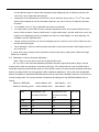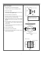
1
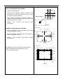
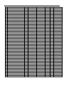
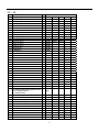
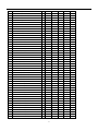
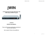
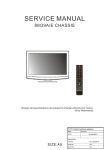
.
SERVICE MANUAL
CHASSIS
: Mitsubishi
DOCUMENT : SM-20PM
DATE
: 08/08/2005
This manual is the latest at the time of print, and does not include the modification which
may be made after the printing, by the constant improvement of product.
.
1.
CONTENTS
Safety precautions…………………………………………………………………………..……………1
2.
Service adjustment……………………………………………………………..………………………...2
3.
Purity
4.
List of Parts ………………………………………………………………………….…………………….10
5.
Circuit
/ convergence adjustment……………………………………………………………………..8
Diagram……………………………………………………………………………Attached
.
1. SAFETY
PRECAUTIONS
1.
The design of this product contains special hardware, many
circuits and components especially for safety purposes. For
continued protection, no changes should be made to the original
design unless authorized in writing by the manufacturer.
Replacement parts must be identical to those used in the
original circuits. Service should be performed by qualified
personnel only.
2.
Alterations of the design or circuitry of the products should not
be made. Any design alterations or additions will void the
manufacturer’s warranty and will further relieve the
manufacturer of responsibility for personal injury or property
damage resulting therefrom.
3.
Many electrical and mechanical parts in the products have
special safety-related characteristics. These characteristics are
often not evident from visual inspection nor can the protection
afforded by them necessarily be obtained by using replacement
components rated for higher voltage, wattage, etc.
Replacement parts which have these special safety
characteristics are identified in the parts list of Service manual.
Electrical components having such features are identified by
shading on the schematics and by ( ! ) on the parts list in
Service manual. The use of a substitute replacement which
does not have the same safety characteristics as the
recommended replacement part shown in the parts list of
Service manual may cause shock, fire, or other hazards
those components that indicate evidence of overheating should
be replaced. Always use the manufacturer’s replacement
components.
9. Isolation Check
(Safety for Electrical Shock Hazard)
After re-assembling the product, always perform an isolation
check on the exposed metal parts of the cabinet (antenna
terminals, video/audio input and output terminals, Control knobs,
metal cabinet, screw heads, earphone jack, control shafts, etc.)
to be sure the product is safe to operate without danger of
electrical shock.
10. The surface of the TV screen is coated with a thin film which can
easily be damaged. Be very careful with it when handle the TV.
Should the TV screen become soiled, wipe it with a soft dry
cloth. Never rub it forcefully. Never use any cleaner or detergent
on it.
4.
Don’t short between the LIVE side ground and ISOLATED
(NEUTRAL) side ground or EARTH side ground when
repairing. Some model’s power circuit is partly different in the
GND. The difference of the GND is shown by the LIVE: (
)
side GND, ISOLATED (NEUTRAL): (
) side GND and
EARTH: (
) side GND. Don’t short between the LIVE side
GND and ISOLATED (NEUTRAL) side GND or EARTH side
GND and never measure with a measuring apparatus
(oscilloscope etc.) the LIVE side GND and ISOLATED
(NEUTRAL) side GND or EARTH side GND at the same time. If
above note will not be kept, a fuse or any parts will be broken.
5.
If any repair has been made to the chassis, it is recommended
that the B1 setting should be checked or adjusted (See
ADJUSTMENT OF B1 POWER SUPPLY).
6.
The high voltage applied to the picture tube must conform to
that specified in Service manual. Excessive high voltage can
cause an increase in X-Ray emission, arcing and possible
component damage, therefore operation under excessive high
voltage conditions should be kept to a minimum, or should be
prevented. If severe arcing occurs, remove the AC power
immediately and determine the cause by visual inspection
(incorrect installation, cracked or melted high voltage harness,
poor soldering, etc.). To maintain the proper minimum level of
soft X-Ray emission, components in the high voltage circuitry
including the picture tube must be the exact replacements or
alternatives approved by the manufacturer of the complete
product.
7.
Do not check high voltage by drawing an arc. Use a high
voltage meter or a high voltage probe with a VTVM. Discharge
the picture tube before attempting meter connection, by
connecting a clip lead to the ground frame and connecting the
other end of the lead through a 10kΩ 2W resistor to the anode
button.
8.
When service is required, observe the original lead dress. Extra
precaution should be given to assure correct lead dress in the
high voltage circuit area. Where a short circuit has occurred,
(1)
(2)
Dielectric Strength Test
The isolation between the AC primary circuit and all metal parts
exposed to the user, particularly any exposed metal part having
a return path to the chassis should withstand a voltage of 3000V
AC (r.m.s.) for a period of one second.
(…Withstand a voltage of 1100V AC (r.m.s.) to an appliance
rated up to 120V, and 3000V AC (r.m.s.) to an appliance rated
200V or more, for a period of one second.)
This method of test requires test equipment not generally found
in the service trade.
Leakage Current Check
Plug the AC line cord directly into the AC outlet (do not use line
isolation transformers during this check). Using a “Leakage
Current Tester”, measure the leakage current from each
exposed metal part of the cabinet, particularly any exposed
metal part having a return path to the chassis, to a known good
earth ground (water pipe, etc.). Any leakage current must not
exceed 0.5mA AC (r.m.s.).
However, in tropical area, this must not exceed 0.2mA AC
(r.m.s.).
●Alternate Check Method
Plug the AC line cord directly into the AC outlet ( do not use a
line isolation transformer during this check.). Use an AC
voltmeter having 1000 ohms per volt or more sensitivity in the
following manner. Connect a 1500Ω 10W resistor paralleled by
a 0.15μF AC-type capacitor between an exposed metal part and
a known good earth ground (water pipe, etc.). Measure the AC
voltage across the resistor with the AC voltmeter. Move the
resistor connection to each exposed metal part, particularly any
exposed metal part having a return path to the chassis, and
measure the AC voltage across the resistor. Now, reverse the
plug in the AC outlet and repeat each measurement. Any
voltage measured must not exceed 0.75V AC (r.m.s.). This
corresponds to 0.5mA AC (r.m.s.).
However, in tropical area, this must not exceed 0.3V AC
(r.m.s.).
This corresponds to 0.2mA AC (r.m.s.)
一、Enter Factory Menu
1) Entrance of factory controller: Use factory key to enter/switch/exit factory mode. Entrance of common
controller: When main menu appears, enter code 6483, which is equivalent to factory key.
2) Specification: Factory mode includes three kinds: FACTORY: for factory aging; B/W BALANCE:for
adjustment of black and white balance; ADJUST:for all adjustments of factory.
Pressing factory key (or pressing 6483 when main menu appears) will display the following:
Common state
FACTORY
B/W BALANCE
ADJUST
二、Factory Explanation
1、 FACTORY (Aging mode): This mode is used for factory aging, in which TV set will not be turned off if
there is no signal.
2、 Adjustment of B/W BALANCE: Press factory key to enter into B/W BALANCE and set value as table 1;
press “MUTE” key to enter horizontal line, and then adjust grid potentiometer to make the horizontal line
to bright up; adjust CUT R, CUT G AND CUT B (See table 2) to make the line turn white; and then adjust
grid potentiometer to make the line disappear. Press “MUTE” key to exit the line and dark balance is OK.
Fine tuning DRI R and DRI B to make the white to become pure white; and B/W BALANCE is OK.
Table 1
OSD
Explanation
14″-21″
25″-34″
DRI R
Adjust range of output R (0~127)
60
60
DRI B
Adjust range of output B(0~127)
63
63
CUT R
Adjust base level of output R(0~255)
100
100
CUT G
Adjust base level of output G(0~255)
100
100
CUT B
Adjust base level of output B(0~255)
100
100
BRI
Adjust brightness of horizontal line(0~255)108
120
SIG
8 second built-in signal
Indication
Table 2
Key Name
1
2
3
Function
CUT R+
CUT G+
CUT
Key Name
4
5
6
Function
CUT R-
CUT G-
CUT
B+
B-
Note: BRI is only for adjusting voltage of grid, not for SUB-brightness; so please set BRI value as the
above table. It is better not to make any changes. If it needs to make change, please make it within the
range 14″-21″:100-120;25″-34″:110-130.
2
3、 ADJUSTMENT
Explanation of adjustments and settings: There are 11 pages for adjustments and settings from “SERVCJ0”
to “SERVCJ9” and “AUTO VCJ”. It is available to turn down the page with MUTE key and swiftly arrive the
set page with 0-9 keys. Use P+/P- to select the adjusted item; and use VOL+ or VOL- to make set
adjustment.
0) Page SERVCJ0
No.
Name
Explanation
0
H PH
Line center (range: 0~31)
1
V SH
Vertical center (range: 0-7)
2
V SI
Vertical range (range: 0-63)
3
V SC
Vertical correction SC (range: 0-63) (effective only when choosing
M61264)
4
V LI
Vertical linearity (range: 0-63) (effective only when choosing M61264)
5
N H PH
Deviation amount of line center in NTSC (range: -31~+31)
6
N V SH
Deviation amount of vertical center in NTSC (range: -7~+7)
7
N V SI
Deviation amount of line center in NTSC (range: -63~+63)
8
N V SC
Deviation amount of vertical correction SC in NTCS (range: -63~+63)
(effective only when choosing M61264)
9
N V LI
Deviation amount of vertical linearity in NTCS (range: -63~+63)
(effective only when choosing M61264)
1) SERVCJ1
No.
Name
Explanation
30
0
AGC
RF.AGC adjustment (range: 0~127)
1
1
HT
Half-transparent switch (0: off; 1: on)
2
AUDIO
Audio output (range: 0~127); effective only when the value of PWM
100
OPT of SERVCJ4 is more than 0.
3
YDL
Time delay adjustment of brightness(0~7)
4
VDL
V delay adjustment L (0~3)
5
UDL
U delay adjustment (0~3)
6
YUV TINT
YUV tincture adjustment (0~127)(effective only in YUV mode)
(effective only in YUV mode)
(effective only in YUV mode)
2
0
0
50
2) Page SERVCJ2 (effective only in M61260)
No.
Name
Explanation
0
S BL R
Adjustment of SECAM R-Y signal(0~31)
16
1
S BL B
Adjustment of SECAM B-Y signal(0~31)
16
2
S YDL
Time delay compensation of SECAM( 0:off 1:on)
0
3
S BPG
Time delay option of SECAM BGP(0~3)
0
3
3)Page SERVCJ3
No.
Name
Explanation
0
IC
Option of decoding CMOS chip (M61260/M61264/M61266)
1
SEA CHACK
Checking of automatic channel searching when TV set is turned on.(0: 1
no
M61264
1:yes)
2
CAL
Option of calendar (1:yes/ 0:no)
1
3
GAME
Option of game (0:no /1: yes)
1
4
ZOOM
Option of ZOOM (1:yes/ 0:no)
1
5
LOCK
Option of child lock (1:yes/ 0:no)
0
6
CURT
Option of screen stretching (0:no / 1:on / 2:off / 3:both)
3
7
WOO
Option of bass(0:no 1: base switch
0
8
SAVER
Option of screen protection (0:no 1:yes
2:digital control)
2:uper line LOGO 3: two line 1
LOGO)
4)Page SERVCJ4
0
HP
Left/right of OSD (range: 0~60)
28
1
VP
Up/down of OSD (range: 0~60)
29
2
Z1
Vertical range data when screen is enlarged (range: 0~63)
58
3
Z2
Vertical range data when screen is widened (range: 0~63)
30
4
CURT TIM Time option of black screen before stretching screen when TV set is turned on 4
(range: 0~30 seconds)
5
PWM
Volume option (0: inner volume control;, 1: 1-circuit PWM output; 2:2-circuit
0
PWM number, 3: IC control of acoustics)
6
AV option (0:1-circuit AV
AV
1: 2-circuit AV
2:1-circuit AV, 1-circuit YUV 0
3: 2-circuit AV,1-circuit YUV)
7
S SYS
Option of sound system (see note 1)
01111
8
POW
Option of turning-on state ((0:direct turning on 1:turning on after standby 2:2
memory turning on)
Note 1: display
0
0
0
0
0
D/K
I
BG
M
5.742
As shown in the fig., the sound will be opened when each of the corresponding sound system is in 1 position;
and closed when in 0.
4
5)Page SERVCJ5
0
V FREQ
Option of middle frequency: 38.0MHZ、38.9MHZ、39.5MHZ、45.75MHZ、
38.0
34.47MHZ
1
V VCO
Tuning of middle frequency: when tuning, AFT of the last line in the menu is in
26
OK mode.
2
V GAIN
Scale control of video output(0~7)
7
3
H VCO
Tuning of horizontal frequency (range: 0~7)
3
4
C TR
limiting of color waves(0 ~ 3)(ineffective when tuning in terminal S or YUV input) 0
6)Page SERVCJ6
0
BS SW
black level extending switch:
0:on/1:off
1
BS CHAG
(0~3)controlling of extending scale of black level(0~3)
2
2
BS DIS
(0~3)controlling of extending scale of black level(0~3)
0
3
BS GAIN
Gaining switch of black level extending: 0:normal、1:enhance
0
4
GAMMA
(0~3)Correction of curve GAMMA(0~3)
0
5
A SW
limiting switch of automatic contrast: 0:control of automatic contrast, 1: 0
0
limiting of automatic contrast.
6
A GAIN
ABCL gaining switch 0:low, 1:high
0
7
OM DET
Checking of modulation: 0:off, 1:on
0
8
M/N
ption of PAL-N,PAL-M
0
0:off, 1:on
7)Page SERVCJ7
0
D OSD
OSD digit 1:off
0:on
0
1
OSD L
Output scale of OSD digit: 0:low 1:high
1
2
S DOWN
Sync cutting mode:
0: 50%, 1: 40%, 2: 30%, 3: 25%
3
R MIX
Adjustment of matrix R: 0:normal 1:enhance
1
4
VSY DET
Switch of sync time testing: 0:11.5us
0
5
BLACK SCR
Option of screen blackening
6
VOL CHOICE
Option of acoustics curves:
1:20.5us
2
1
0:standard
1:customer
0
8)Page SERVCJ8
0
SUB CONT
Sub-contrast 0~29
18
1
SUB BRI
Sub-brightness 0~105
20
2
SUB COL
Sub-color 0~27
18
5
3
SUB SHA
Sub-sharpness 0~13
13
4
SUB TI
Sub-tincture 0~27
10
5
SA BR
Screen protection and brightness of blueness in no-signal mode 0~255
138
6
LAN CHOICE
Language option: 0: only English, 1: Chinese, English
1
7
TUNER
TUNER OPTION: 0:VS TUNER, 1: FS TUNER
0
CHOICE
9)Page SERVCJ9 (effective only in choosing M61266)
0
Cr ADJ
Adjustment of base level Cr (0~15)
1
Cb ADJ
Adjustment of base level Cb (0~15)
2
SIF45 GAIN
Attenuation of output scale of NTSC acoustics (0:0dB
1:-6dB)
3
SIF PAL
enhancing of PAL SNR(0:OFF
4
SIF PAL INV
Polarity switch of SIF PAL(0: NORMAL
5
AMF
Testing switch of weak radio-frequency signal(0:OFF
6
AMF VTH
Level adjustment of weak radio-frequency signal testing
7
AMF CUR
reduce filtering current of MF AGC(0: NORMAL 1: CURRENT
1: ON)
1: INVERT)
1:ON)
REDUCED)
8
AMF HYS
Switch HYS (0: OFF
1: ON)
10)Page AUTO VCJ: This menu automatically adjusts VIF VCO and S TRAP; and save the adjusted data in
EEPROM. Pressing volume key begins the automatic adjustment and it will return to original mode 2~3
seconds after adjustment.
Note 1: the adjusted datum will be shown in SER VCJ5.
Note 2: Adjusting will not affect any keys.
0
S TRAP
1
VIF VCO
三、Explanation of Special Function
1. Enter factory LOG set: press “LOGO” key will directly enter into adjusting mode; or in “AV” indication for
common controller in AV state, successively input 6483 will also enter into adjusting mode.
2、Setting of factory LOGO: There are two lines for factory LOGO, the 1st of which is “Double Happiness” or
defined by customer; the 2nd of which is for customer to define (it is available for customer to set not more
than 13 characters). And customer may set switch, font, color, up/down position and left/right position. If
“LOGO” in the menu is set in “ON” position, the screen will show the equivalent “LOGO” when there is on
signal in POWER-ON state.
•
The setting menu of factory logo is displayed on two screens, which are available to adjust the 1st
line and 2nd line of the LOGO separately. After entering the setting menu, press POS+/POS to
6
choose different options. Yellow block will appear when displaying item is selected, and then use
VOL+/VOL- key to adjust the selected item.
•
Adjustment of the selected item: use RECALL key to select the shown item in 1st or 2nd line, when
yellow block indicates the current selectable character, use VOL+/VOL key to adjust the selected
character.
•
It is available to use “0” key to eliminate the current set character.
•
On setting menu, press DISPLAY key to indicate adjustment effect, and re-press DISPLAY key to
return LOGO set menu. Factory LOGO set is in “to gain what is seen”; and the other items, color, font,
position in the displaying lines are completely the same in normal display. So, while adjusting, it is
available to see the adjusted effect.
•
Setting of items in two lines. Do not set overlapping (even if one line is set in OFF position) so as to
prevent abnormal display.
•
When adjusting V POS, the menu probably may flash, but this will not affect LOGO display when TV
set is turned on.
3.Note: After setting, change screen protection mode through factory setting item. Please see Page
SERVCJ3 for details.
6-2、Realization of factory automatic adjustment
Note: There is no any effect for any key in BUS OPEN mode.
Pin 13 of CPU is the automatic adjustment ENABLE terminal; high level should be kept in normal
working state. When the terminal is connected to low level, CPU will transfer the control of BUS LINE to
automatic equipment (automatically enter into “BUS OPEN” mode); and the automatic equipment will send
data to decoding CMOS chip through BUS LINE to implement adjustment. Then it will save the adjusted
data in the address of equivalent EEPROM and recover the high level in ENABLE terminal. CPU returns to
normal working state. The concerned data of automatic decoding piece and EEPROM address are as
follows:
Address of EEPROM:
written address: A0H
Address of decoding piece:
Name
written address: BAH
read address:
A1H
read address:
BBH
Sub-address in the
Sub-address in the
equivalent EEPROM
equivalent decoding
Max value
piece
R.DIR
3BH
0BH
7FH
B.DIR
3CH
0CH
7FH
R.CUTOFF
3DH
0DH
FFH
G.CUTOFF
3EH
0EH
FFH
B.CUTOFF
3FH
0FH
FFH
7
PURITY / CONVERGENCE ADJUSTMENT
8
PURITY ADJUSTMENT
1.
Demagnetize CRT with the demagnetizer.
2.
Loosen the retainer screw of the deflection yoke.
3.
Remove the wedges.
4.
Input a green raster signal from the signal generator,
and turn the screen to green raster.
WEDGE
DEFLECTION YOKE
P
CRT
5.
Move the deflection yoke backward.
6.
Bring the long lug of the purity magnets on the short
lug and position them horizontally. (Fig2)
4 6
P/C MAGNETS
7.
Adjust the gap between two lugs so that the GREEN
RASTER will come into the centre of the screen.
(Fig. 3)
8.
Move the deflection yoke forward, and fix the position
of the deflection yoke so that the whole screen will
become green.
9.
Insert the wedge to the top side of the deflection yoke
so that it will not move.
P: PURITY MAGNET
4: 4-POLES (convergence magnets)
6: 6-POLES (convergence magnets)
Fig. 1
PURITY MAGNETS
Long lug
10. Input a crosshatch signal.
11. Verify that the screen is horizontal.
12. Input red and blue raster signals, and make sure that
purity is properly adjusted.
Short lug
Bring the long lug over the short lug and
position them horizontally.
Fig. 2
(FRONT VIEW)
GREEN RASTER
CENTER
Fig. 3
9
STATIC CONVERGENCE ADJUSTMENT
1. Input a crosshatch signal.
2. Using 4-pole convergence magnets overlap the red
and blue lines in the center of the screen (Fig. 1) and
turn them to magenta (red/blue).
(FRONT VIEW)
3. Using 6-pole convergence magnets overlap the
magenta (red/blue) and green lines in the center of the
screen and turn them to white.
4. Repeat 2 and 3 above, and make the best
convergence.
Fig. 1
(FRONT VIEW)
DYNAMIC CONVERGENCE ADJUSTMENT
1. Move the deflection yoke up and down and overlap
lines in the periphery. (Fig. 2)
2. Move the deflection yoke left to right and overlap the
lines in the periphery. (Fig. 3)
3. Repeat 1 and 2 above, and make the best
convergence.
RED
GREEN BLUE
BLUE
RED
GREEN
GREEN
RED
BLUE
BLUE
GREEN
RED
Fig.2
(FRONT VIEW)
After adjustment, fix the wedge at the original position.
Fasten the retainer screw of the deflection yoke.
Fix the 6 magnets with glue.
RED GREEN
BLUE
BLUE
GREEN
RED
RED
GREEN
BLUE
BLUE
GREEN
RED
Fig. 3
10
List of Parts
14” ~ 21”
Description
Q’ty
4
VD902
1
VD561
1
HZ5C2(5.1V)
2
6.2V 1W/IN4735A
3
HZ7C2(7.5V)
1
VD519
4
HZ9A2(8.2V)
4
VD601
VD110
Location
VD111
VD452
VD602
VD603
VD904
5
UPC574/CW574
1
VD101
6
IN4148
13
VD133
VD203
VD514
VD516 VD518
VD537
VD538
VD903
VD914
VD600
VD607
VD608
VD609
7
IN4002(10L)
1
VD451
8
IN4002(12.5L)
1
VD135
9
FR154(12.5L)
2
VD448
VD517
3
VD553
VD554
VD555
VD504
VD505
V553
V604
10 FR154(12.5LH)
11 FR157(12.5LH)
1
VD552
12 HER308(20LH)
1
VD551
13 RL207(12.5L)
4
VD503
14 2SA1015Y
1
V600
15 2SC1815Y
3
V102
16 2SC1815GR
1
V191
17 2SC1674/2SC388A
1
V101
18 HSB772P/3CA8772/B764
1
V511
19 2SC2383-O
4
V901
V132
V133
20 HBF422
3
V651
V652
V653
21 2SC3807
1
V512
22 2SC5296/TT2190
1
V413
23 ST1802/2S5297
1
V513
24 PC817B/Q817/F817
1
N501
25 ATME24C08/24LC08
1
N602
26 AN5522/ST9302
1
N451(N401)
27 TDA2003
M37160M8-058FP or
28 M37160M8-063FP or
M37160M8-064FP
29 M61266
1
N301
1
N601
1
N101
30 F3828H(38MHz)
1
Z101
31 JA18B-4.43MHZ(S)
1
Z601
32 CBB21-250V-684J
1
C441
33 CBB62-250V-224K
1
C501
34 CBB81-1.6KV-103J
1
C436
35
2
C605
36 CC1-SL-50V-181J
1
C604
37 CC1-50V-101J
1
C719
C606
38 CC1-50V-221J
2
C601
C715
39 CT1-50V-471K
3
C122
C713
C621
40 CT1-50V-331K
2
C622
C623
11
VD506
V701
41 CT1-50V-102K
3
C119
C611
C721
42 CT1-50V-103Z
17
C101
C102
C115
C116
C121
C198
C205
C207
C211
C315
C629
C708
C711
C716
C718
C903
C905
C554
43 CT1-500V-471K
3
C553
44 CT1-500V-102K
1
C930
45 CT1-500V-392K
1
C931
46 CT81-B-1KV-471K
2
C551
C552
47 CT81-B-1KV-102K
2
C503
C505
48 CT81-B-2KV-681K
1
C516
49 CT81-B-2KV-102K
1
C630
50 CT7-400VAC-222M
1
C535
51 CL11-100V-222K
1
C306
52 CL11-100V-472K
1
C312
C901
C555
53 CL11-100V-103K
3
C124
54 CL11-100V-153K
1
C603
55 CL11-100V-333K
1
C456
56 CL11-100V-104K
5
C307
57 CL21X-63V/100V-153J
2
C515
C517
58 CL21X-100V/63V-104J
3
C117
C401
C514
CL21X-100V/63V-224J
3
C108
C118
C191
59 CL21X-100V/63V-474J
1
C433
60 CL21X-100V/63V-334J
1
C402
61 CD110-16V-10UF-M
5
C110
C131
C144
C1
C808
62 CD110-16V-47UF-M
2
C628
C923
63 CD110-16V-100UF-M
7
C104
C114
C212
C814
C904
C380
C600
C706
C438
C203
64 CD110-16V-220UF-M
2
C206
65 CD110-16V-470UF-M
1
C130
C906
66 CD110-16V-1000UF-M
1
C564
67 CD110-25V-470UF-M
2
C565
C362
68 CD110-25V-1000UF-M
2
C455
C316
69 CD110-35V-47UF-M
1
C932
70 CD110-35V-100UF-M
1
C452
71 CD110-35V-470UF-M
1
C563
72 CD110-35V-1000UF-M
1
C453
73 CD110-50V-0.22UF-M
1
C125
C363
74 CD110-50V-0.47UF-M
1
C123
75 CD110-50V-1UF-M
7
C165
C304
C308
C602
C902
C215
76 CD110-50V-3.3UF-M
1
C454
77 CD110-50V-4.7UF-M
7
C105
C106
C107
C303
C309
78 CD110-160V-100UF+20%
1
C561
79 CD110-250V-4.7UF-M(Φ5)
1
C444
80 CD110-250V-22UF-M
1
C562
81 CD293-400V-100UF-M
1
C507
12
C451
C366
C109
C113
82 JLC-96-37UH/YDD-37UH
1
L401
83 LGA0307-151K
1
L600
84 LGA0307-1R2K
1
L101
85 LGA0307-100K
2
L133
86 LGA0307-100K
1
L103
87 LGA0307-330K
1
L601
88 LGA0410-180K(12.5)
1
R599
89 RJ-1/4W-2.2K-1%
1
R526
90 RT-1/6W-1-J
1
R453
91 RT-1/6W-2.2-J
1
R362
92 RT-1/6W-27-J
1
R102
93 RT-1/6W-33-J
1
R611
94 RT-1/6W-56-J
3
R621
L644
R622
R623
95 RT-1/6W-82-J
1
R823
96 RT-1/6W-100-J
12
R105
R114
R126
R129
R203
R204
R722
R824
R671
R672
R673
R606
97 RT-1/6W-180-J
3
R604
R605
98 RT-1/6W-220-J
2
R110
W230
99 RT-1/6W-270-J
1
R107
100 RT-1/6W-470-J
2
R115
R198
R117
RT-1/6W-560-J
1
R454
101 RT-1/6W-330-J
3
R631
R632
R633
102 RT-1/6W-1K-J
5
R104
R112
R205
103 RT-1/6W-1.8K-J
2
R523
R310
104 RT-1/6W-2.2K-J
8
R601
R545
R641
R101
R103
R119
R712
R816
105 RT-1/6W-4.7K-J
6
R517
R716
R602
R603
R727
R642
R643
R111
106 RT-1/6W-5.6K-J
2
R511
R553
107 RT-1/6W-6.8K-J
5
R307
R614
R724
R725
R901
108 RT-1/6W-10K-J
6
R113
R120
R600
R711
R903
R515
R556
R719
R720
R211
R730
W165
109 RT-1/6W-12K-J
1
R461
RT-1/6W-15K-J
1
R462
110 RT-1/6W-22K-J
6
R457
R723
111 RT-1/6W-47K-J
3
R207
112 RT-1/6W-100K-J
1
R815
113 RT-1/4W-3.3-J
1
RR452
114 RT-1/4W-4.7-J
1
R363
115 RT-1/4W-22-J
1
R519
116 RT-1/4W-100-J
1
R800
117 RT-1/4W-150-J
1
R914
118 RT-1/4W-220-J
1
R361
119 RT-1/4W-270-J
1
R938
120 RT-1/4W-470-J
1
W161
13
121 RT-1/4W-1K-J
2
R180
R930
122 RT-1/4W-1.2K-J
2
R917
R936
123 RT-1/4W-2.2K-J
2
R906
R726
124 RT-1/4W-4.7K-J
3
R312
R701
R702
125 RT-1/4W-10K-J
4
R116
R703
R713
126 RT-1/4W-15K-J
3
R121
R522
R560
127 RT-1/4W-22K-J
1
R731
128 RT-1/4W-120K-J
1
R904
129 RT-1/4W-1M-J
1
R907
R693
130 RT-1/2W-270-J
1
R466
131 RT-1/2W-1K-J
1
R443
132 RT-1/2W-2.7K-J
3
R691
R692
134 RT-1/2W-22K-J
2
R440
R448
135 RT-1/2W-100K-J
1
R552
136 RT-1/2W-120K-J
2
R520
137 RT-1/2W-150K-J
1
R554
133
138 RT-1/2W-220K-J
2
R501
139 RY(15)-1/2W-1K-J
1
R441
140 RY(15)-1/2W-1.8-J
1
R452
141 RY(20)-1W-12-J
1
R142
142 RY(20)-1W-39-J
1
R709
143 RY-1W-47K-J
1
R555
144 RY-2W-1-J(17.5LH)
1
R562
145 RY-2W-1.5-J(17.5LH)
1
R437
146 RY-2W-12-J(17.5LH)
2
R133
147 RY-2W-270-J(15LH)
1
R436
148 RY-2W-12K-J(20LH)
4
R551
R524
2
R525A
1
VD436
151 RS11-1/2W-12M-K
1
R531
152 MF72-2-7-M
1
R502
153 MZ72-14RM
1
RT501
154 WI06-2-2K-M
1
RP551
1
U101
1
T471
157 JBC-145-UU10.5
1
T901
158 BCK40-45-1275
1
T511
159 JLF-98-UF16
1
L501
160 T3.15AL250VAC
1
FUSE
161 Fuse Clip
2
FUSE
162 GZS10-2-108C
1
CRT
163 TJC1-1A
1
GND
156 21" BSC24-01N4006E
R134
R682
150 RXG-5W-8.2-J
ET-5G1E-CV100(063Y)(38MHz)
/ET-5CE-V01
R558
R681
149 RY-3W-68-J(20LH)
155
R521
14" BSC24-01N4010G/
BSC24-01N4010GA
164 TJC1-2A
2
XS501
165 TJC2-5A(DY)
1
XS901
166 TJC2-5A(L=7)
1
XS408
XS502
14
R683
R902
167 TJC3-2A
3
XS303
168 TJC3-3A
2
XS702
169 TJC3-4A
2
XS402
170 TJC3-5A
1
XS601
171 YG-2A
1
XP451
172 TJC3-4Y-450mm
1
XP602
173 TJC3-5Y-450mm
1
XP601
XS302
XS703
XS803
XS701
174 21MMT1
1
V513
175 21MMHV2
1
V413
176 21MMB1-1
1
N301
24
W130
W176
W199
W203
W212
W214
W231
W309
W360
W366
Bare Wire
182 5mm
183 7.5mm
184 10mm
18
16
W429
W439
W504
W515
C810
C936
L430
R580
XS1
W112(1)-W213(3)
W600
W601
W602
W606
W1
W132
W133
W134
W151
W168
W170
W174
W178
W179
W184
W185
W192
W206
R820
W511
R308
W152
L502*2
W147
W148
W164
W172
W173
W181
W182
W204
W431
W507
W149
W162
W177
W201
W183
R416
W155
W603
185 12mm
1
C807(-)-R818(8)
186 12.5mm
6
W137
W190
187 14mm
1
N801(2)-W210)
188 15mm
11
W100
W131
W135
W153
W157
W158
W159
W186
W187
W209
W438
R814(4)-W211
(1)
W141
W142
W156
189 16mm
1
190 17.5mm
5
W188
W189
191 20mm
5
W143
1
RT-1/6W-1.5K-J
1
R1015
2
RT-1/6W-2.4K-J
1
R702
3
RT-1/6W-3.6K-J
1
R701
4
RT-1/6W-3.9K-J
1
R703
5
RT-1/6W-6.2K-J
1
R704
6
RT-1/6W-12K-J
1
R705
7
CD110-16V-47UF-M
BRM-1040/FPS-6038-T53
/MIM-5383K4 /MIM-5383J2/
MIM-5383K4-F-5
1
C1101
1
RM
8
W154
15
W169
W202
N301:1-9
25” ~ 34”
Description
1
2
3
4
5
6
HZ5C2(5.1V)
6.2V 1W/1N4735A
HZ7C2(7.5V)
HZ9A2(8.2V)
UPC574/CW574
IN4148
7
8
9
10
11
12
13
14
15
17
18
IN4002(10L)
IN4002(12.5L)
FR154(12.5L)
FR154(12.5LH)
FR157(12.5LH)
FR305(12.5LH)
BY228(20LH)
SF36(20LH)
RL207(12.5L)
2SA1015Y
2SC1815Y
19
20
21
22
23
24
25
26
27
29
30
31
32
2SC1815GR
2SC1674/2SC388A
HSB772P
2SC2383-O
2SC2688
2SC3807
2SC5296
2SC4460-M
D2012
LTV817B
ATME24C08/24LC08
TDA8177
AN7522
M37160M8-058FP/M37160M8H-051FP
33 or M37160M8-063FP or
M37160M8-064FP
34 M61266
35 MCI4053B/HEF4053/CD4053/HCF4053
37 F3828H
38 JA18B-4.43MHZ(S)
39 CBB21-630V-473J
40 CBB21-400V-684J
41 CBB62-250VAC-224K
42 CBB81-1.6KV-103J
43 CBB81-1.6KV-822J
44 CC1-SL-50V-181J
45 CC1-50V-101J
Q’ty
3
1
2
4
1
13
1
1
2
3
1
1
1
1
4
1
7
1
1
1
4
3
1
1
1
1
1
1
1
1
Location
VD902 VD110 VD111
VD561
VD519 VD452
VD601 VD602 VD603 VD904
VD101
VD133 VD203 VD514 VD516 VD518
VD537 VD538 VD903 VD914 VD600
VD607 VD608 VD609
VD451
VD135
VD448 VD517
VD553 VD554 VD555
VD552
VD436
VD435
VD551
VD503 VD504 VD505 VD506
V600
V102 V110
V201
V553
V604 V830
V831
V191
V101
V511
V901 V132
V133 V701
V651 V652
V653
V512
V413
V513
V303
N501
N602
N451
N301
1 N601
1
1
1
1
1
1
1
1
1
1
1
N101
N801
Z101
Z601
C433
C441
C502
C436
C439
C604
C719
16
46 CC1-50V-221J
47 CC1-50V-22PF-J
C601
C605
C622
C122
C119
C101
C198
C629
C800
C715
C606
C623
C621
C611
C102
C205
C708
C903
C721
C115
C207
C711
C905
CT1-500V-471K
CT1-500V-102K
CT1-500V-392K
3 C553
1 C930
1 C931
C554
C555
CT81-B-1KV-471K
CT81-B-1KV-102K
2 C551
4 C503
C552
C505
C504
CT81-B-2KV-102K
2 C630
C516
CT7-400VAC-472M
CL11-100V-222K
CL11-100V-472K
CL11-100V-103K
1
1
2
3
1
1
3
C535
C306
C311
C124
C312
C901
C603
C456
C203
C307
2
3
3
1
1
C515
C117
C108
C402
C451
CT1-50V-331K
48 CT1-50V-471K
49 CT1-50V-102K
50 CT1-50V-103Z
51
52
53
54
55
56
57
58
59
60
62
63
64
CL11-100V-153K
66 CL11-100V-333K
67 CL11-100V-104K
68
69
70
71
CL21X-63V/100V-153J
CL21X-100V/63V-104J
CL21X-100V/63V-224J
CL21X-100V/63V-334J
CL21X-100V/63V-474J
CL21X-100V/63V-224J
72 CD71S-50V-10UF-M
73 CD71-160V-4.7UF-M
74 CD110-16V-10UF-M
75 CD110-16V-47UF-M
76 CD110-16V-100UF-M
77
78
79
80
81
82
83
84
CD110-16V-220UF-M
CD110-16V-470UF-M
CD110-16V-1000UF-M
CD110-25V-2200UF-M
CD110-35V-47UF-M
CD110-35V-100UF-M
CD110-35V-470UF-M
CD110-35V-1000UF-M
2
2
2
3
3
18
1 C302
1 C444
15 C1
C704
C809
2 C628
6 C104
C600
2 C206
1 C130
3 C564
1 C455
1
1 C452
1 C563
1 C453
17
C517
C401
C118
C110
C801
C810
C923
C114
C713
C116
C211
C716
C121
C315
C718
C506
C906
C438
C514
C191
C131
C802
C811
C144
C807
C812
C314
C808
C896
C212
C814
C904
C706
C316
C565
C932
85 CD110-50V-0.22UF-M
86 CD110-50V-0.47UF-M
87 CD110-50V-1UF-M
88 CD81-50V-4.7UF-M (105℃)
89 CD110-50V-4.7UF-M
90
91
92
94
95
96
97
98
99
100
101
102
103
104
105
106
107
108
109
110
111
CD110-160V-220UF-M
CD110-250V-22UF-M
CD293-400V-220UF-M
18UH
410UH
LGA0307-151K
LGA0307-1R2K
LGA0307-100K
LGA0307-100K
LGA0307-330K
LGA0410-180K(12.5)
RJ-1/6W-22K±1%
RJ-1/6W-15K±1%
RJ-1/4W-2.2K±1%
RT-1/6W-1-J
RT-1/6W-27-J
112
113
114
115
116
117
RT-1/6W-180-J
RT-1/6W-220-J
RT-1/6W-270-J
RT-1/6W-470-J
RT-1/6W-300-J
RT-1/6W-1K-J
RT-1/6W-33-J
RT-1/6W-56-J
RT-1/6W-68-J
RT-1/6W-82-J
RT-1/6W-100-J
118 RT-1/6W-1.5K-J
119 RT-1/6W-1.8K-J
120 RT-1/6W-2.2K-J
122 RT-1/6W-3.3K-J
123 RT-1/6W-4.7K-J
124 RT-1/6W-5.6K-J
125 RT-1/6W-6.8K-J
126
1 C125
1 C123
8 C165
C602
1 C454
8 C105
C303
1 C561
1 C562
1 C507
1 L401
1 L301
1 L600
1 L101
2 L133
1 L103
1 L601
1 R599
1 R457
1 R462
1 R526
1 R453
1 R102
1 R611
3 R621
1 R806
3 R817
14 R105
R203
R722
3 R604
2 R110
1 R107
3 R115
3 R631
9 R104
R517
1 R317
1 R523
11 R111
R641
R307
1 R835
12 R101
R712
R822
1 R511
4 R614
18
C304
C617
C308
C902
C320
C366
C106
C309
C107
C310
C109
C113
R129
R672
R833
R198
R673
L644
R622
R623
R823
R114
R204
R818
R605
W230
R890
R126
R671
R824
R606
R117
R632
R112
R716
R454
R633
R205
R803
R222
R804
R316
R601
R643
R602
R727
R603
R306
R103
R743
R119
R814
R553
R309
R816
R310
R820
R724
R725
R901
R642
R545
127 RT-1/6W-10K-J
6 R113
128 RT-1/6W-12K-J
129
130 RT-1/6W-22K-J
1 R461
R120
R600
R711
R903
R515
R808
R556
R832
R719
R211
R813
R815
R819
R702
R713
R560
R830
R440
R902
W165
131
132 RT-1/6W-47K-J
133 RT-1/6W-68K-J
134 RT-1/6W-100K-J
135
136
137
138
139
140
141
142
143
144
145
146
147
148
149
150
151
153
154
155
156
157
158
159
160
161
163
164
165
166
167
168
169
170
171
172
173
174
RT-1/6W-270K-J
RT-1/6W-8.2M-J
RT-1/4W-22-J
RT-1/4W-22-J
RT-1/4W-100-J
RT-1/4W-150-J
RT-1/4W-270-J
RT-1/4W-470-J
RT-1/4W-1K-J
RT-1/4W-1.2K-J
RT-1/4W-2.2K-J
RT-1/4W-4.7K-J
RT-1/4W-10K-J
RT-1/4W-15K-J
RT-1/4W-22K-J
RT-1/4W-120K-J
RT-1/4W-1M-J
RT-1/2W-3.3-J
RT-1/2W-270-J
RT-1/2W-1K-J
RT-1/2W-2.7K-J
RT-1/2W-22K-J
RT-1/2W-100K-J
RT-1/2W-120K-J
RT-1/2W-150K-J
RT-1/2W-220K-J
RY(15)-1/2W-1K-J
RY(15)-1W-1.2-J
RY(20)-1W-12-J
RY(15)-1W-5.1-J
RY(20)-1W-39-J
RY-1W-47K-J
RY-1W-560-J(15LH)
RY(17.5)-2W-1-J
RY(17.5)-2W-1.5-J
RY(17.5)-2W-12-J
RY(15)-2W-270-J
RY(20)-2W-10K-J
9 R315
R720
2 R207
1 R313
6 R801
R821
1 R314
1 R300
1 R519
1 R224
1 R800
1 R914
1 R938
1 W161
2 R180
2 R917
2 R906
3 R312
5 R116
4 R121
2 R731
1 R904
1 R907
1 RR452
1 R466
1 R443
3 R691
1 R448
1 R552
2 R520
1 R554
2 R501
1 R441
1 R452
1 R142
1 R330
1 R709
1 R555
1 R463
1 R562
1 R437
2 R133
1 R436
3 R681
19
R723
R730
R802
R930
R936
R726
R701
R703
R522
R831
R692
R693
R521
R558
R134
R682
R683
175
176
177
178
179
180
181
182
RY-2W-15K-J(20LH)
RS11-1/2W-12M-K
RXG-7W-2.2-J
RY-2W-1-J
RXG-5W-22-J(15)
RXG-5W-39-J(15)
MZ73-14RM
WI06-2-2K-M
1
1
1
1
1
1
1
1
R551
R531
R502
R580
R524
R525A
RT501
RP551
185 ET-5G1E-CV100(063Y)/ET-5CE-V01
1 U101
186
187
188
189
190
191
192
193
194
197
198
199
200
201
202
203
204
205
207
208
1
1
1
2
1
2
1
1
1
1
2
1
1
4
2
3
1
1
1
1
BSC26-01N4010A
JBC-184-E119
BCK40-45-1243-1
JLF-148-ET24
T3.15AL250VAC
Fuse Clip
SW-3K
GZS10-2-108C
AV6-14
TJC1-1A
TJC1-2A
TJC2-5A(DY)
TJC2-5A(L=7)
TJC3-2A
TJC3-3A
TJC3-4A
TJC3-5A
YG-2A
TJC3-4Y-500mm
TJC3-5Y-500mm
Bare Wire
223 5MM
224 7.5MM
225 10MM
226 12.5MM
227 15MM
228 17.5MM
T471
T901
T511
L501
FUSE
FUSE
S-IN
CRT
AV2
GND
XS501
XS901
XS408
XS301
XS702
XS402
XS601
XP451
XP602
XP601
23 W130
W214
W439
W602
W310
19 W1
W168
W184
W152
14
W164
W183
8 W137
W171
13 W100
W158
W438
5 W141
20
L502
XS502A
XS302 XS703 XS1
XS102
XS701 XS803
W176
W231
W504
W606
W362
W132
W170
W185
W211
W147
W172
W204
W149
L430
W131
W159
W160
W142
W199
W360
W515
C804
C362
W133
W174
W192
W604
W148
W173
W431
W162
W190
W135
W186
W208
W156
W203
W366
W600
C936
W212
W429
W601
W210
W134
W178
W206
W151
W179
W512
W507
W177
R308
W155
W182
R416
W201
W153
W187
W157
W209
W188
W189
W603
W181
229
230
231
232
233
234
235
236
20MM
RT-1/6W-1.5K-J
RT-1/6W-2.4K-J
RT-1/6W-3.6K-J
RT-1/6W-3.9K-J
RT-1/6W-6.2K-J
RT-1/6W-12K-J
CD110-16V-47UF-M
BRM-1040/FPS-6038-T53
237 /MIM-5383K4
/MIM-5383J2/MIM-5383K4-F-5
4 W143
1
1
1
1
1
1
1
R1015
R702
R701
R703
R704
R705
C1101
1 RM
21
W154
W169 W202
彩色电视机电路电原理图
1
n
i
L
10K
0
0
0
R681
2SJ10K
V651
2SC2482
R641
2.2K
R691
1/2SJ2.7K
R631
330
C621
R314
270K
+ C310
50V1
CJ330
+ C309
50V1
R673
100
R310
4.7K
R683
2SJ10K
V653
2SC2482
R693
1/2SJ2.7K
8
7
10K
+
+
R827
220
R643
2.2K
V830
2SC
R830
R831
22K
VD111
5V
+
9
V831
2SC
0
10
0
11
0
14
0
C801
16V10
15
0
R802
100K
R803
1K
R671
100
C312
FK.0047
C311
R835
8.2K
R808
22K
B901
10W8OHM
R833
1k
C899
16V10
R633
330
C623
R309
4.7K
R682
2SJ10K
CJ330
+
C802
16V10
0
+
16
R801
100K
0
V201
2SC
0
R806
47
W814
J
N801
XS301
SCN3-2Y
HEF4053
0
C804
J
Rout
0
+ C814
16V47
R224
68
+
t
u
o
L
Vout
11
6
CRT BOARD
XS301
TJC3-2A
12
4
B901
10W8OHM
LO
5
13
10
12
LO
3
0
B6
8V
0
0
R814
1k
XS302
TJC3-2Y
FK.0047
+
C807
16V10
R813
100K
GND
2
1
+ C303
16V10
R712
B6
8V
8
R816
1K
9
C314
16V10
V604
2SC
16V10
VOL
22K
+ C617
16V10
1K
7
+ C704
16V10
6
R833
82
+
2
n
i
L
Rin2
C808
16V10
R315
+
Vin2
R815
100K
R317
1.5K
C894
104
5
C896
R894
120
+
R824
100
R893
75
3
C812
R316
R818
100
R822
1K
C315
103
16V1000
4
75
R823
100K
R821
100K
R819
2
+
R820
1K
C809
16V10
XS302
TJC3-2A
AN7522
IC301
+ C316
1
16V10
C811
16V10
B2
10V
C892
104
LIN
75
R817
C810
16V10
R892
120
RIN
1
R891
75
GND
1
Cr
STBY
2
Cb
RO
2
Y
GND
3
RO
Vin1
4
VCC
S-3K
S-IN
4
3
+
Rin1
R804
1K
R672
100
+
IF
C401
50V1
+
C191
FK0.22
R101
4.7K
4
5
AGC
R743
4.7K
B1
110V
R116
10K
R121
15K
C118
FK0.22
C113
50V4.7
C119
102
R551
2SJ12K
7
8
+
VD101
UPC574J
9
V191
2SC
C701
101
10
2
GND
N702
SDA
B5
5V
21
C706
16V100
SDA
SAFTY
SCL
RESET
AV2
VCC
R726
2.2K
C905
103
D603
6.2V
31
30
R603
2.2K
R604
100
D602
6.2
D601
6.2
R606
100
R601
2.2K
17
R907
X
18
C906 R906
103 2.2K
19
23
24
C711
103
26
C202
101
R716
1K
C713
471
C201
101
28
C716
103
29
L503
LQ0003
C501
250HM0.1
R501
1/2DJ220K
R525
5W68
10
R524
5W56
C513
FK4700
R511
5.6K
25"SC5299
C514
FK0.1
R519
22
VD518
D
VD551
HER308
V513
2SD1710
VD516
D
R523
3.3K
R517
1K
V512
2SC3807
13
R554
150K
AUDIO BYPASS
R OUT
AUDIO OUT
SIF MAX(INTER CARRIER)
B OUT
SW 5.7V
H-VCO
SIF IN
MONITOR
SW 8.7V
HSYC
SECAM PLL(Cr)
VSYC
PAL ID(Cb)
B-IN
AUDIO/RGB VCC(8V)
G-IN
DDS FILTER
R-IN
VGREG VCC (8.7V)
53
1
4
2
K6D
+
+
C305
50V1
52
51
C304
50V1
B4
24V
N451
LA7840
L451
R599
50
R308
2.2K
49
C307
100n
C452
35V100
48
R453
1
R466
1/2DJ330
VD452
1Z75
C453 +
35V1000
46
C451
100FK0.1
R460
1SJ1K
XS402
TJC2-5A
4
VD451
IN4002
47
R454
470
R462
3.9K
45
R457
22K
+ C453
50V3.3
R461
12K
44
3
C456
100FK0.033
XP402
TJC2-5Y
+ C455
25V2200
43
L601
33UH 181
42
VD914
IN4148
R562
2FJ1
B2
10V
C165
50v1
R134
2FJ12
C707
16V10
R142
1FJ12
V133
C2655
B4
24V
VIDEO/CROM VCC(5V)
SDA
DRIV VCC (5V)
SCL
EXT/C IN
STANDBY
CROM PLL
CLK OUT
V/C GND
RESET
DRIVE GND
CVBS OUT
XTAL
MCU 5.7V OUT
ABL
C206
103
39
C205
16v100
B7
5V
C353
FK0.1
38
R614
6.8K
C603
15n
36
C602
50V1
+
+
B5
5V
R356
39K
35
+
R354
10K
C354
FK0.1
4.43M(S)
4.43
34
R357
5.6K
C601
121
33
R359
18K
R371
2.7K
R211
47K
R207
47K
VD351
D
VR351
B-50K
B6
8V
V352
2SA
C365
102
C932
35V47
V901
C23830
R930
1k
R437
1FJ2.2
C930
102
C931
392
R371
4.7k
C355
35V47
SCN-4Y
V413
2SD1651
XP601 XS601
R374 10
XS402
R416
220K
25" 2SD5296
T901
184-E119
B3
190V
HV
L430
YC0008
FO
R936
1.2K
SCN-5Y SCN-5
R370
2.7K
+ C444
160V1
+
VR352
B-10K
R358
39K
400V474
VD902
HZ5C2
C439
1.6KV103
SCREEN
AFC
C436
1.6KV822
VD435
FR309
8
R330 L301
410UH
5.1
FBT
V303 + C302
2SD880
50V4.7
C433
630V473
VD436
FR305
T471
B1
110V
25" 128V
R545
2.2K
C203
100n
TP-G
TEST
TP-H
TEST
D1 D
D2
R443
1K
R130
47K
R561
22K
10
9
8
11
SLEEP
WOO
12
ZOOM
8
GAME
7
7
6
14
15
5
13
D3 D
4
3
2
1
X1
455
C1
221
FK0 .1
3V
+
C1
16V10
VD904
8.2V
D
C438
C2
221
VD1
IR-LED
4
DISP
16
9
6
2
POWER
AV/TV
RECALL
MUTE
CA
-/---
MENU
17
18
19
20
0
3
V+
P-
5
1
P.P
V-
LOG
P+
FAT
R2
220
R1
1
2SC
V1
注意事项:
C402
C605
C606
R117
R891
M61260
47CH
NONE
NONE
1U
102
103
224
jumper
none
none
none
none
M61264
N0NE
104
104
104
334
NONE
NONE
390
75
75
100
100
C129
VD903
D
+
C892
C894
C401
R893
R892
R894
(1) 2SC: 2SC536-E/F/G; 2SC1815-O/Y/GR;
R401
R457
C455
27K
22K
22OOU
(2) 2SA: 2SA608-E/F; 2SA1015-O/Y/GR;
NONE
39K
3300U
(3) D: 1S1555; 1N4148; 1S2473; 1S2076; D5442;
(4) 0.01:CT1-08B-2F4-63V-0.01uF-Z;
(5) KK470: CT1-06B-2B4-63V-470uF-K
(6) FKXXX: CL11-63V-XXXuF-K
嗢
C212
16V470
C144 +
16V10
V351
2SC
1K
C441
R436
2W/270
35V47
C351
R352
100K
R353
270K
R335
R132
100K
B7
5V
C130
16V470
+ C923
16V47
C713
16V470
1/2SJ1K
R351
8.2K
C207
103
40
37
R441
35V1000
V552
2SC
R565
3.9K
V132
2SC
C131
16V10 +
R914
270
V701
C2655
C533
400KM2200S
CLK CONT
41
V580
2SC
R599
1FJ2.2
R709
1FJ39
C565
25V1000
TV/Y IN
L401
18UH
R459
1SJ1
B4
26V
C352
R556
22K
V551
2SB892
+
VD555
FR154
FB-IN
R555
1/2DJ47K
VD561
HZ6C3
R564
10K
R133
2FJ12
VD554
FR154
9
+
LIVE AREA
+ C563
35V470
C554
500V470
C517
FJ0.015
R531
1/2CK12M
EXT AUDIO IN
FO
25"130V
R553
5.6K
R560
1SJ15K
C515
FJ0.015
C532
400KM470S
DEF VCC
B1
110V
V553
2SC
RP551
B-2K
B1-ADJ
VD553
FR154
1
2
C630
2KV1000
XP602
SCN-4Y
HZ9C2
R551
2SJ47K
+ C564
16V1000
R515
DJ22K
SW501
KDC-A05/06
R510
2SJ0.22
R526
2.7K
B
C306
222
C366
50v1
VD561
R552
1/2DJ100K
C551
2KV470
14
VD519
HZ7C1
R558
1/2DJ220K
C561
160V220
+
8
B3
190V
+ C562
250V22
VD552
FR157
7
12
V511
2SA
FU501
T3.15AL250V
11
C516
2KV680
L504
Z2073
R522
15K
VD517
ES1
L501
LQ0002
L909
LJ0107CHA
3
R521
1/2SJ120K
C507
400V220
VD514
D
R502
6WK3.9
32
T511
R520
1/2SJ120K
G
2
C117
100n
54
+
00
RT501
MZ72-14
C502
250HM0.1
31
C518
1000KK1000E
3
1
7
55
+
27
C552
2KV470
N501
PC817B
VD506
RM11C
00
~220V
50HZ
3
+
2
XS502
EW0130KB
2
4
5
R122
1k
22
30
1
FM DIRECTOR OUT
G OUT
U901
XXXXXXX
10
C604
22
R204
100
VD505
RM11C
VIF VCO
VDD OUT (NC)
6
8
9
R611
33
R
4
1
FBT IN
H-DRE
B6
12V
56
24
25
D
SIF GND
57
23
R724
4.7K
C504
C506
1000KM1000E 1000KM1000E
XS501
1 TJC2-2A
16
VIF GND
R307
6.8K
27
C503
C505
1000KM1000E 1000KM1000E
VD504
RM11C
15
R602
2.2K
R205
1K
VD503
RM11C
14
R605
100
R203
100
VD133
13
21
FILT
VSS
12
C903 C904
103 16V100
20
CCD HLF
PLL NC
R917
1.2K
LOGIC GND
C308
50V1
R115 R180
1k
470
25
CCD (V-HOLD)
PLLGND
11
DEF GND
V110
2SC
11
XP601
SCN-5Y
5
26
CCD CVBS
CNVSS
R902
10k
33
28
CLK IN
AV1
34
R903
10k
R938
270
29
POWER
V-PROTEC
V190
2SA
R192
4.7k
32
CLK CONT
KEY
MUTE
10
35
N601
M37160
5
R725
4.7K
X-RAY
9
R904
120k
SCN-5
58
JG0034
XS601
+
SCL
AT24C04
4
7
6
FB
R190
10k
TV OUT
R306
6.8K
+
3
+
SCN-4A
VCC
20
POETEC
38M
R193
10k
H-PLL
W902
C122
471
59
CRTP
GZS10-2-108C
1
19
C703
103
304HD
8
R
36
7
FK0.018
C901 8
R901
6.8k
+
C902
50V1
K9N
TJC2-1A
C320
50V1
2
VD669
1
18
R708
1K
B
G
W111
J
Z101
K926E
RF AGC
R117
470
C124
.01
GND
R701
4.7K
10
37
NC
IR
R111
82
VD101
D
V-FB
60
OUTPUT
C710
16V100
17
R109
1K
R115
2.2K
VIF PLL
4
+
XS701
16
R710
HS0038
38
AFT IN
6
V102
2SC2216 C112
0.01
V-DRIV
3
15
R702
4.7K
VSYC
40
C110
0.01
5
R112
6.8K
VCC1
R706
100
A701
14
VOL-R
R110
220
16v100
103
C123
50V0.47
5
R703
4.7K
R771
1.5K
R772
2.7K
HSYC
R108
5.6K
+
C212
C211
C110 +
16v10
61
INPUT
R773
3.9K
NC
VIF AGC(SECAM BELL)
41
39
MONITOR
IF AGC
SIF VCC (5V)
7
R774
4.7K
R775
775
VOL-L
4
6
13
R776
27K
VL
VIF VCC (5V)
+
VCC2
12
P/N
B7
5V
CJ330
NON INPUT
R731
22K 11
VH
B6
8V
R107
100
B6
8V
R110
220
50V.22
PUMP OUT
R727
C719
101
R119 2.2K
4.7K
SW703 SW704 SW705 SW706
V+
VMENU AV/TV
SW701 SW702
CH+
CH-
6
C721
102
VT
C111
0.01
R632
330
C622
C125
62
IC1
M34282M2
TU
42
UH
63
+
UH
3
S-IN
64
+
VH
C108 +
FK0.22
R120
10K
2
R719
22K
C107 +
50V4.7
C109
50V4.7
1
VL
+
C106
50V4.7
R113
10K
R720
22K
MB
IF IN1
+
+
R692
1/2SJ2.7K
R642
2.2K
+
+
C105
50V4.7
3
IF IN2
AFT OUT
N101
C104
16V100
C115 C114
103 16V100
+
L103
10UH
C116
103
V RAMP CAP
68K
+
GND
2
C121
103
+
1
TDC-XXX
V652
2SC2482
R313
M61260/M61264
B5
5V
R401
27K
+
C402
102
A101
本原理图仅供参考,如有
更改,恕不另行通知