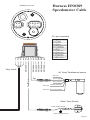
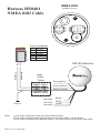
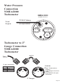
1
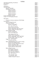
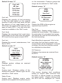
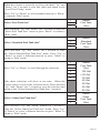
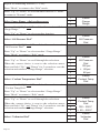
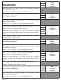
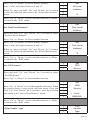
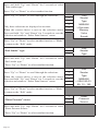
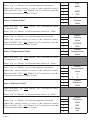
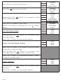
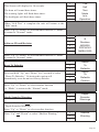
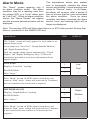
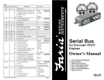
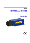
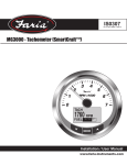
Owner’s Manual
NMEA2000 MG2000
Tachometer
IS0189
rev. B ecr#6583 12/2006
Standard Operating Conditions
Description
Figure 1
Operation
Normal Mode
Display Contrast
Displayed Functions
Default screen 1
Default screen 2
Default screen 3
Default screen 4
Default screen 5
Figure 2 Default screens
Figure 3 LCD Display Screens
Index
Edit Mode
Functions that are adjusted in Edit Mode.
Instructions
Select “Default Screen”
Local Fuel Config
Reset “Fuel Used”
Set “Fuel Tank Full”
Set “Amount of Fuel”
Select “Fuel Tank Size”
Select “Standard Fuel Tank Size”
Select “Other Fuel Tank Size”
Fuel Totalizer Config
Reset “Tfuel Used”
Set “TFuel Tank Full”
Total Amount of Fuel
Select “TFuel Tank Size”
Select “Standard TFuel Tank Size”
Select “Other TFuel Tank Size”
Set “Totalizer Mode”
Organize user screens
Organize Screen 1
Select Gauge Range (dial reading range)
Select “Oil Pressure Dial”
Select “Coolant Temperature Dial”
Select “Voltmeter Dial”
Select “Water Pressure Dial”
Select “Boost Pressure Dial”
Select Data Sources
Set “Engine Instance”
Set “Battery Instance”
Set “Oil Level Instance”
Set “Fuel Level Instance”
Set “GPS Source”
“Trim Sender” type
“Fuel Sender” type
“Water Pressure” source
page 1
page 1
page 1
page 1
page 2
page 2
page 3
page 3
page 3
page 4
page 4
page 4
page 5
page 6
page 7
page 7
page 8
page 8
page 8
page 8
page 8
page 9
page 10
page 10
page 10
page 11
page 11
page 11
page 12
page 12
page 12
page 13
page 13
page 14
page 14
page 15
page 15
page 15
page 15
page 16
page 16
page 17
page 17
page 17
page 17
page 18
page 18
page 18
page 19
page 19
Calibrate Trim Sender
Select Display Units
Select “Pressure Units”
Select “Volume Units”
Select “Temperature Units”
Select “Distance Units”
Select “Depth Units”
Fuel Tank Calibration
Low Fuel Alarm Setting
Adjust “Low Fuel Alarm” Setting
Select “Self Test”
Select “Software ID and Revision”
Depth Sounder Warnings
Set Depth Sounder Shallow Warning
Set Depth Sounder Deep Warning
Set Depth Sounder Keel Offset
page 20
page 20
page 20
page 21
page 21
page 21
page 21
page 22
page 23
page 23
page 23
page 24
page 24
page 25
page 25
page 25
Alarm Mode
Standard Alarms
Low Fuel
Depth Shallow
Depth Deep
Check Engine
Over Temperature
Low Oil Pressure
Low Oil Level
Low Fuel Pressure
Low System Voltage
Low Coolant Level
Water Flow
Water In Fuel
Charge Indicator
Preheat Indicator
High Boost Pressure
Rev Limit Exceeded
EGR System
Throttle Position Sensor
Engine Emergency Stop
page 28
page 28
page 28
page 28
page 29
page 29
page 29
page 30
page 30
page 30
page 30
page 30
page 30
page 30
page 30
page 30
page 30
page 31
page 31
page 31
page 31
Table - Deutsch Pin Connector wiring diagram
Table - NMEA 2000 MG2000 Tachometer PGN’s Supported
Harness HN0389 - Tachometer/Speedometer Cable
Harness HN0401 - NMEA 0183 Cable
Harness
- Water Pressure (Tachometer)
Harness
- 2 inch Gauge Connection
page 32
page 34
page 35
page 35
page 38
page 38
rev A 120805
changes 122005
finish 122105
rev B 120206
PGFXXX
FARIA NMEA 2000 CAN bus
MG2000 Tachometer Manual Oil Pressure
On
Off
Standard Operating Conditions
20.1 PSI
Voltage: 12 - 24V
System,
19.3
PSI (10.5 – 32
V operating, 36 V max operating, 1
Hr.)
65˚ F
Temperature: 0° - 158° F
Shock Resistant per MIL-STD-202,
50G
Oil Pressure
On Off
Humidity: 0% - 98% Rel
20.1 PSI
Vibration Resistant per SAE J1455
19.3 PSI
Water and Weather
Resistant: IP66 (from front only)
65˚ Fper ASTMCorrosion Resistant
B117-73, 48 Hr
20 Feet
PGFXXX
Fuel Left
Faria
47
Gal
RPM
3650
KLine
Fuel Used
miniGal
17.5
Gateway
Fuel Inst
11.6GPH
Gal
7.3
PGFXXX
The Faria MG2000 Tachometer combines
Oil Pressure
the features of an ECU On
serial Off
bus gateway
and several instruments into one unit: 20.1 PSI
• The tachometer is analog but
19.3 PSI
driven by a stepper motor for digital
accuracy.
• The high resolution
65˚ FLCD screen
displays information for many other
functions and the various “screens”
can be configured as the user
Oil Pressure
On Off
wishes. As received,
the screens
are configured as shown in Fig. 1. 20.1 PSI
19.3 PSI
The MG2000 receives digital engine
data from the Engine Control Unit (ECU)
65˚ Fbus and can
via the NMEA 2000 CAN
receive GPS information via a NMEA
0183 connection to a suitable GPS unit.
GPS information is displayed in the
On Off
MG2000 speedometer. Analog inputs
are provided for two non-engine sensors
such as fuel level19.3
and trim
PSI position. A
direct pressure port allows monitoring of
engine water pressure.
65˚ F
The MG2000 provides a Faria Bus output
to allow use of various other 5, 4, and 2
inch instruments with the MG2000.
Engine Temp
Faria
136
˚F
KLineRPM
3650
Engine
Hours
325mini
Hours
Gateway
Depth
Volts
13.6
Volts
Trip
RPM
3650
Sen Trim
93.5
Miles
Water Press
20 GPH
PSI
7.3
RPM
Trip
3400
3650
RPM
93.5
Miles
Sen Fuel
Oil Pressure
7.3
40 GPH
PSI
ALARM
SCREEN
Trip
WILL
93.5DISPLAY
Miles
ENGINE
AND LOCAL
ALARMS WHEN
7.3OCCUR
GPH
THEY
Figure 1
Trip
93.5 Miles
Page 1
The Faria MG2000 Tachometer will turn
on when the ignition key is turned on
and will turn off when the ignition key is
turned off.
buttons to enter the “Edit” menus.
Operation
The unit will power up showing the “Self
Test Mode Is In Operation” then switch to
the last saved default screen.
Note: The warning LEDs will flash when
there is no ECU data present. If this
happens check the connection to the
NMEA 2000 bus and ensure the unit is
connected properly.
The instrument has three push buttons;
“Down”, “Mode”, and “Up”;
that control the functions available. The
“Mode” button is used to change the
function of the LCD display and to access
submenus and adjustable settings.
The “Down” and “Up” buttons are used to
modify the settings.
In “Normal“ operation mode, pressing
the “Mode” button for a short period of
time and then pressing “Down” or “Up”
causes the display to cycle between the
available screens.
Press and hold the “Mode” and “Up”
When the “Edit” menus have been
selected, pressing the “Mode” button
for a short period of time causes the
instrument to return to “Normal” mode.
Press the “Down” or “Up” button to cycle
between the available “Edit” functions.
Press and hold the “Down” and “Up”
buttons for two (2) seconds’s to select an
“Edit” function to change.
Within each “Editing” function the “Down”
or “Up” buttons select settings or subfunctions. Follow the instructions in the
“Edit” mode section of this manual to
save the new settings after you select /
adjust them.
Normal Mode
When the MG2000 is turned on, the unit
enters the “Self Test” mode. The screen
will display “The Self Test Mode Is In
Operation” for 10 seconds. The horn will
sound three times, the warning lights will
flash three times, and the backlights will
flash three times. When this is complete,
the user selected “Default” screen will
appear. The information below applies
to the MG2000 with no user changes to
the screen selections.
Contrast and Lighting
In the “Normal“ operating mode the
instrument display contrast and display
mode can be adjusted by pressing the
“Down” and “Up” buttons.
Page 2
data directly from Faria
the ECU so no settings
are required.
KLine
A microprocessormini
controlled stepper
motor moves Gateway
the pointer to display
engine revolutions per minute.
With the display in “Positive” mode, black
on white, pressing the “Down” button
decreases the contrast. Pressing the
Oil Pressure
“Up” button increases contrast.
Continuing to press the “Up” button
causes the display to reverse to the
“Negative” mode, white on black. The
contrast in this mode is controlled the
same way as the “Positive” mode.
20.1 PSI
PGFXXX
3650 RPM
Default Screen “1”
Engine Temp
To return to “Positive” mode, continue to
Onuntil
Off
press the “Down” button
the display
reverses.
Engine Hours
19.3
325 Hours
PSI
136 ˚F
Depth
65˚ F
To adjust the lighting intensity of all of
the instruments in the system, press and
hold both the “Down” and “Up” buttons
for 2 seconds. The lighting intensity may
now be adjusted by using the “Down” or
“Up” buttons.
Return to the “Normal” mode by pressing
and holding both the “Down” and “Up”
buttons for 2 seconds.
Displayed Functions
Tachometer
The tachometer is a digital instrument
with the appearance of an analog
instrument. The tachometer receives
Page 3
20 Feet
Engine Temp
Displays the coolant / cylinder head
temperature received from the ECU.
Dial range can be selected in the “Edit”
function.
Engine Hours
Displays the Engine
Hours data received
7.3 GPH
from the engine ECU.
Depth
Trip sunder data (if
Displays the depth
installed and on
the
93.5engine
Miles bus) received
from the engine.
Default Screen “2”
on the tachometer. Pressure gauge dial
range can be selected in “Edit” mode.
Fuel Left
47 Gal
Default screen “4”
Fuel Used
17.5 Gal
On
Off
RPM
41˚21N 072˚06W
3400
Fuel Inst
11.6
GalPSI
19.3
Fuel Left
F remaining
Displays the quantity 65˚
of fuel
in the fuel tank based on the original
quantity of fuel in Faria
the tank when full and
KLine
the amount of fuel
used based on the
GPH from the engine
miniECU and the time
spent at each GPH.
Fuel tank size and
Gateway
reset are available
the “Edit” mode.
7.3inGPH
P
Sen Fuel
S
Oil Pressure
40 PSI
RPM
Display the RPM of the engine as
reported from the ECU.
Sen Fuel
Analog input. Display setting of the
PGFXXX
Fuel Used
analog fuel level sender. This display is
7.3
GPH fuel gauge
Displays the amount of fuel used since the equivalent of
a standard
Trip
reset based on the GPH from the engine and should be used as the reference for
Oil Pressure
ECU and the time
spent
at each GPH.
the fuel remaining.
93.5
Miles
RPM
3650
20.1 PSI
Trim Sync Trip
Fuel Inst
Each filled block represent 1/8 of a tak
93.5 Miles
Displays the current, instantaneous, fuel and when the fuel tank is empty, only
flow in GPH.
empty blocks will be displayed. For best
accuracy, the fuel level sender should
Default screen “3”
be calibrated as described.
Oil Pressure
Volts
3650 RPM
20.1 PSI
Oil Pressure
13.6 Volts
Displays oil pressure as received from
Sen Trim
the ECU.
17.5072˚06W
Gal
41˚21N
Water Press
Default screen “5”
20 PSI
P
S
ALARM
On
Off
Volts
Displays system voltage as received
from the ECU.
19.3 PSI
Trim
65˚ F
Analog input. Displays setting of the
analog trim sender. Sender type can be
7.3
GPH
selected in “Edit”
mode.
Water Press
Analog input. Displays
engine water
Trip
pressure as supplied
to
the
93.5 Miles pressure port
SCREEN
WILL DISPLAY
ENGINE
AND LOCAL
ALARMS WHEN
THEY OCCUR
This screen displays fault conditions
based on engine data received from
the ECU or alarms based on internally
set alarm points. Engine alarms from
the ECU will be displayed as “Check
Page 4
Engine !” or “Engine Emergency Stop
!”. Accessing the “View“ mode when the
Alarm screen appears will allow more
information to be displayed about the
alarm, if provided by the engine.
Internal alarm values can be set for “Low
Fuel” and other functions. Alarms for
these settings will appear as required.
Screen “1”
Default
Screen “2”
Screen “3”
LCD Display Screens:
In “Normal” mode, press “Mode” once to
enter screen “Select” mode,
Screen “4”
Screen “5”
Alarms
(only available if
Alarms are active)
press “Up” or “Down” to move between
screens. (See Figure 2)
Figure 2
Press “Mode” once to return to “Normal”
mode.
Page 5
1.
2.
3.
4.
5.
6.
7.
8.
9.
10.
11.
12.
13.
14.
Select Default Screen
Local Fuel Configuration
Fuel Totalizer Configuration
Organize User Screens
Select Gauge Range
Select Data Sources
Calibrate Trim Sender
Select Display Units
Fuel Tank Calibrate
Low Fuel Alarm
Select Self Test
Software ID & Revision
Reset To Defaults
Depth Sounder Warnings
Page 6
Edit Mode
The “Edit” mode is used to adjust or set the values of numerous functions and
options in the MG2000. The procedure below specifies the steps to be taken in the
“Edit” mode to adjust / set each option.
To enter “Edit” mode, press “Mode” and “Up” buttons while in “Normal” mode.
To return to “Normal” mode, press “Mode” button once while in “Edit” mode.
Functions that are set or adjusted in the “Edit” mode.
1.
2.
3.
4.
5.
6.
7.
8.
9.
10.
11.
12.
13.
14.
Page 7
Select Default Screen
Local Fuel Configuration
Fuel Totalizer Configuration
Organize User Screens
Select Gauge Range
Select Data Sources
Calibrate Trim Sender
Select Display Units
Fuel Tank Calibrate
Low Fuel Alarm
Select Self Test
Software ID & Revision
Reset To Defaults
Depth Sounder Warnings
Instructions – Function
Select Default Screen
LINE
1
2
3
DISPLAY
Select
Default
Screen
1
Default
2
Display
3
Screen:
4
1
1
Default
2
Display
3
Screen:
4
X
1
2
3
Local
Fuel
Config
1
2
3
Reset
Fuel
Used
Press and hold “Up” and “Down” for 2 seconds to select
“Default Screen.”
Press “Up” or “Down” to select another function or “Mode”
to return to “Normal” mode.
(Display Screen 1 is the “Default” at first turn on.)
Press and hold “Up” and “Down” for 2 seconds to select
Screen 1 as the “Default Screen” and exit.
Press “Up” or “Down” to select another Screen.
Press and hold the “Up” and “Down” for 2 seconds to select
this Screen as the “Default Screen” and exit.
Press “Up” or “Down” to select another Screen.
Repeat until desired “Default Screen” is selected.
Press “Up” or “Down” to select another function or “Mode”
to return to “Normal” mode.
Local Fuel Config
Press and hold “Up” and “Down” for 2 seconds to choose
“Local Fuel Config.”
Press “Up” or “Down” to select another function.
“Reset Fuel Used”
Page 8
Press and hold “Up” and “Down” for 2 seconds to reset
“Fuel Used” to zero (0).
Automatically resets fuel used to zero and returns to “Local
Fuel Config” menu.
Press “Up” or “Down” to select another function or “Mode”
to return to “Edit” mode.
Set “Fuel Tank Full”
1
2
3
Set
Fuel Tank
Full
1
2
3
Set
Amount
of Fuel
1
2
3
Fuel
Amount
XXX
NOTE: In order to use the “Fuel Left” function, the owner
must set this function when the fuel tank is filled or use the
set current amount of fuel below. In addition, if “Set Fuel
Tank Full” function is used, the “Fuel Tank Size” must be
set correctly to the size of the fuel tank in this application.
The computer will monitor fuel usage and calculate the fuel
left in the tank. This function does not replace the fuel level
function provided by the fuel sender and should be used with
caution.
Press and hold “Up” and “Down” for 2 seconds to set “Fuel
Tank Full.”
Automatically sets the fuel available to the tank size selected
by the user and returns to “Local Fuel Config” menu.
Press “Up” or “Down” to select another function or “Mode”
to return to “Edit” mode.
Set “Amount of Fuel”
NOTE: If a known amount of fuel is in the fuel tank but it
is not full, this function can be used to indicate the amount
of fuel available. The “Fuel Left” function will then use the
amount of fuel entered to calculate the “Fuel Left.”
Press and hold “Up” and “Down” for 2 seconds to select
“Set Amount of Fuel.”
Press “Up” or “Down” to select another function or “Mode”
to return to “Edit” mode.
Press “Up” or “Down” to set the amount of fuel known to be
in the fuel tank. Adjust until the displayed volume matches
the known amount of fuel in the tank.
Page 9
When the volume is correctly set, Press and hold “Up” and
“Down” for 2 seconds to save the value and return to the
“Local Fuel Config” mode.
Press “Up” or “Down” to select another function or “Mode”
to return to “Edit” mode.
Select “Fuel Tank Size”
1
2
3
Select
Fuel Tank
Size
1
2
3
4
Select
Standard
Fuel Tank
Size
1
2
3
4
5
6
Select
Fuel Tank
Size
120 Gal
> 25 Gal
36 Gal
40 Gal
50 Gal
55 Gal
80 Gal
1
2
3
4
Select
Other
Fuel Tank
Size
Press and hold “Up” and “Down” for 2 seconds to enter the
“Select Fuel Tank Size” menu or press “Mode” to return to
“Edit” mode.
Select “Standard Fuel Tank Size”
Press and hold “Up” and “Down” for 2 seconds to enter
the “Select Standard Fuel Tank Size” menu. Press “Up” or
“Down” to select a different function or press “Mode” to
return to “Edit” mode.
Press “Up” or “Down” to scroll through the selections.
Only three selections will show at one time. When the
correct choice is next to the selection arrow, Press and hold
“Up” And “Down” for 2 seconds to save the selection and
return to the “Select Standard Fuel Tank Size” selection.
Select “Other Fuel Tank Size”
Press and hold “Up” and “Down” buttons for 2 seconds to
enter the “Select Other Fuel Tank Size” menu. Press “Up”
or “Down” to select a different function or press “Mode” to
return to “Edit” mode.
Page 10
Press “Up” or “Down” to set the fuel tank size displayed on
the Screen to match your fuel tank size. Line 4 value will
adjust.
When set, Press and hold “Up” and “Down” for 2 seconds
to save the value.
1
Select
2
Other
3
Fuel Tank
4
XX
1
2
3
Fuel
Totalizer
Config
1
2
3
Reset
TFuel
Used
1
2
3
Set
TFuel Tank
Full
Press “Up” or “Down” to select a different function or press
“Mode” to return to “Local Fuel Config” menu.
Press “Up” or “Down” to select a different function or press
“Mode” to return to “Edit” mode.
Fuel Totalizer Config
Press and hold “Up” and “Down” for 2 seconds to choose
“Local Fuel Config.”
Press “Up” or “Down” to select another function.
Reset “TFuel Used”
Press and hold “Up” and “Down” for 2 seconds to reset
“TFuel Used” to zero (0).
Automatically resets total fuel used to zero and returns to
“Fuel Totalizer Config” menu.
Press “Up” or “Down” to select another function or “Mode”
to return to “Edit” mode.
Set “TFuel Tank Full”
NOTE: In order to use the “TFuel Left” function, the owner
must set this function when the fuel tank is filled or use the
set current amount of fuel below. In addition, if “Set TFuel
Tank Full” function is used, the “TFuel Tank Size” must be
set correctly to the size of the fuel tank in this application.
The computer will monitor fuel usage and calculate the fuel
left in the tank. This function does not replace the fuel level
function provided by the fuel sender and should be used
with caution.
Page 11
Press and hold “Up” and “Down” for 2 seconds to set “TFuel
Tank Full.”
Automatically sets the total fuel available to the TFuel
tank size selected by the user and returns to “Fuel Totalizer
Config” menu.
Press “Up” or “Down” to select another function or “Mode”
to return to “Edit” mode.
Total Amount of Fuel
1
2
3
Total
Amount
of Fuel
1
Fuel
Amount
XXX
NOTE: If the known combined amount of fuel is in the
fuel tanks but they are not full, this function can be used
to indicate the amount of fuel available. The “TFuel Left”
function will then use the amount of fuel entered to calculate
the “TFuel Left.”
Press and hold “Up” and “Down” for 2 seconds to select
“Total Amount of Fuel
Press “Up” or “Down” to select another function or “Mode”
to return to “Edit” mode.
Press “Up” or “Down” to set the amount of fuel known to be
in the fuel tanks. Adjust until the displayed volume matches
the known amount of fuel in the tanks.
2
3
When the volume is correctly set, Press and hold “Up” and
“Down” for 2 seconds to save the value and return to the
“Fuel Totalizer Config” menu.
Press “Up” or “Down” to select another function or “Mode”
to return to “Edit” mode.
Select “TFuel Tank Size”
Press and hold “Up” and “Down” for 2 seconds to enter the
“Select TFuel Tank Size” menu or press “Mode” to return to
“Edit” mode.
Select “Standard TFuel Tank Size”
1
2
3
Select
TFuel Tank
Size
1
2
3
4
Select
Standard
TFuel Tank
Size
Press and hold “Up” and “Down” for 2 seconds to enter
the “Select Standard TFuel Tank Size” menu. Press “Up”
or “Down” to select a different function or press “Mode” to
return to “Edit” mode.
Page 12
1
2
3
4
5
6
Select
TFuel Tank
Size
120 Gal
> 25 Gal
36 Gal
40 Gal
50 Gal
55 Gal
80 Gal
1
2
3
4
Select
Other
TFuel Tank
Size
Press “Up” or “Down” until the combined size of all fuel
tanks is displayed on the Screen. Line 4 value will adjust.
1
Select
2
Other
When set, Press and hold “Up” and “Down” for 2 seconds
to save the value.
3
Fuel Tank
4
XX
1
2
3
Set
Totalizer
Mode
Press “Up” or “Down” to scroll through the selections.
When “Set Totalizer Mode” is set to “On,” an additional
default screen will be available that will display TFuel Left,
TFuel Used and TFuel Inst.
1
Select
2
TFuel Tank
3
Size
Press and hold “Up” And “Down” for 2 seconds to save the
selection and return to the “Fuel Totalizer Config” selection
4
On
5
> Off
Press “Up” or “Down” to scroll through the selections. Only
three selections will show at one time.
When the correct choice is next to the selection arrow,
Press and hold “Up” And “Down” for 2 seconds to save
the selection and return to the “Select Standard TFuel Tank
Size” selection
Select “Other TFuel Tank Size”
Press and hold “Up” and “Down” for 2 seconds to enter
the “Select Other TFuel Tank Size” menu. Press “Up” or
“Down” to select a different function or press “Mode” to
return to “Edit” mode.
Press “Up” or “Down” to select a different function or
press
“Mode” to return to “Fuel Totalizer Config” menu.
Set “Totalizer Mode”
Press and hold “Up” and “Down” for 2 seconds to enter
the “Set Totalizer Mode” menu. Press “Up” or “Down”
to select a different function or press “Mode” to return to
“Edit” mode.
Page 13
Press “Up” or “Down” to select a different function or
press
“Mode” to return to “Edit” mode.
Organize User Screens
Press and hold “Up” and “Down” for 2 seconds to select
“Organize User Screens.”
Press “Up” or “Down” to select another function or “Mode”
to return to “Normal” mode.
Organize Screen 1
Press and hold “Up” and “Down” for 2 seconds to select
“Set Up Screen 1.”
Press “Up” or “Down” to select another Screen or “Mode”
to return to “Edit” mode.
Refer to the list of available functions on page 22 in this
ownerʼs manual.
Press “Up” or “Down” to select the function to be displayed
in Screen 1, line 1.
Press and hold “Up” and “Down” for 2 seconds to save the
selection for Screen 1, line 1 and advance to Screen 1, line
2.
Press “Mode” to exit with no change made.
Refer to the list of available functions on page 22 in this
ownerʼs manual.
Press “Up” or “Down” to select the function to be displayed
in Screen 1, line 2.
Press and hold “Up” and “Down” for 2 seconds to save
selection for Screen 1, line 2 and advance to Screen 1, line
3.
Press “Mode” to exit with no change made.
Refer to the list of available functions on page 22 in this
ownerʼs manual.
Press “Up” or “Down” to select the function to be displayed
in Screen 1, line 3.
1
2
3
Organize
User
Screens
1
2
3
Set up
Screen
1
1
2
3
4
Screen 1
Line 1
Function
Disp. Data
1
2
3
4
Screen 1
Line 2
Function
Disp. Data
1
2
3
4
Screen 1
Line 3
Function
Disp. Data
Press and hold “Up” and “Down” for 2 seconds to save
selection for Screen 1, line 3 and jump to set up Screen 1.
Press “Mode” to exit with no change made.
Page 14
Repeat for remaining Screens (2, 3, etc)
Press “Mode” to return to the “Edit” mode.
Press “Up” or “Down” to select another function or “Mode”
to return to “Normal” mode
Select Gauge Range (dial reading range)
Press and hold “Up” and “Down” for 2 seconds to “Select
Gauge Range.”
Press “Up” or “Down” to select another function.
Select “Oil Pressure Dial”
Press and hold “Up” and “Down” for 2 seconds to select
“Oil Pressure Dial.”
1
2
3
Select
Gauge
Range
1
2
3
Select
Oil Pressure
Dial
1
2
3
4
5
6
1
2
3
Select
Oil Pressure
Dial
100 psi
> 60 psi
80 psi
Press “Up” or “Down” to select another “Gauge Range.”
Press “Mode” to return to “Edit” mode.
Press “Up” or “Down” to scroll through the selections.
When the correct choice is next to the selection arrow,
Press and hold “Up” and “Down” for 2 seconds to save the
selection and return to “Gauge Range” selection.
Select “Coolant Temperature Dial”
Press and hold “Up” and “Down” for 2 seconds to select
“Coolant Temp Dial.”
Select
Coolant Temp
Dial
Press “Up” or “Down” to select another “Gauge Range.”
Press “Mode” to return to “Edit” mode.
Press “Up” or “Down” to scroll through the selections.
When the correct choice is next to the selection arrow,
Press and hold “Up” and “Down” for 2 seconds to save the
selection and return to “Gauge Range” selection.
Select “Voltmeter Dial”
Page 15
1
2
3
4
5
1
2
3
Select
Coolant Temp
Dial
100 – 250 F
> 60 – 220 F
Select
Voltmeter
Dial
Press and hold “Up” and “Down” for 2 seconds to select
“Voltmeter Dial.”
Press “Up” or “Down” to select another “Gauge Range.”
Press “Mode” to return to “Edit” mode.
Press “Up” or “Down” to scroll through the selections.
When the correct choice is next to the selection arrow,
Press and hold “Up” and “Down” for 2 seconds to save the
selection and return to “Gauge Range” selection.
Select “Water Pressure Dial”
1
2
3
4
5
1
2
3
Select
Voltmeter
Dial
32 v
>
16 v
Select
Water Press
Dial
Press and hold “Up” and “Down” for 2 seconds to select
“Water Pressure Dial.”
Press “Up” or “Down” to select another “Gauge Range.”
Press “Mode” to return to “Edit” mode.
Press “Up” or “Down” to scroll through the selections.
When the correct choice is next to the selection arrow,
Press and hold “Up” and “Down” for 2 seconds to save the
selection and return to “Gauge Range” selection.
Select “Boost Pressure Dial”
1
2
3
4
5
1
2
3
Select
Water Press
Dial
60 psi
> 45 psi
1
2
3
4
5
6
7
Select
Boost Press
Dial
20 PSI
> 30 PSI
50 PSI
70 PSI
Select
Boost Press
Dial
Press and hold “Up” and “Down” for 2 seconds to select
“Boost Pressure Dial”
Press “Up” or “Down” to select another “Gauge Range”
Press “Mode” to return to “Edit” mode.
Press “Up” or “Down” to scroll through the selections. Only
three selections will show at one time.
When the correct choice is next to the selection arrow,
Press and hold “Up” and “Down” for 2 seconds to save the
selection and return to “Gauge Range” selection
Press “Up” or “Down” to select another “Gauge Range.”
Press “Mode” to return to “Edit” mode.
Press “Up” or “Down” to select another function or “Mode”
to return to “Normal” mode.
Page 16
Select Data Sources
1
2
3
Select
Data
Sources
1
2
3
Set
Engine
Instance
1
2
3
4
5
Set
Engine
Instance
1
2
3
Set
Battery
Instance
1
2
3
4
5
Set
Battery
Instance
1
2
3
Set
Oil Level
Instance
Press and hold “Up” and “Down” for 2 seconds to choose
“Select Data Sources.”
Press “Up” or “Down” to select another function.
Set “Engine Instance”
Press and hold “Up” and “Down” for 2 seconds to select
“Set Engine Instance”.
”Press “Up” or “Down” to select another function.
Press “Up” or “Down” to set the engine instance.
Line 5 value will adjust between 0 and 4.
When set, press and hold “Up” and “Down” for 2 seconds
to save the selection and return to the “Select Data Sources”
menu.
X
Press “Up” or “Down” to select another function or “Mode”
to return to the “Edit” mode.
Set “Battery Instance”
Press and hold “Up” and “Down” for 2 seconds to select
“Set Battery Instance”.
Press “Up” or “Down” to select another function.
Press “Up” or “Down” to set the battery instance.
Line 5 value will adjust between 0 and 15.
When set, press and hold “Up” and “Down” for 2 seconds
to save the selection and return to the “Select Data Sources”
menu.
X
Press “Up” or “Down” to select another function or
“Mode” to return to the “Edit” mode.
Set “Oil Level Instance”
Press and hold “Up” and “Down” for 2 seconds to select
“Set Oil Level Instance”.
Press “Up” or “Down” to select another function.
Page 17
Press “Up” or “Down” to set the battery instance.
Line 5 value will adjust between 0 and 15.
When set, press and hold “Up” and “Down” for 2 seconds
to save the selection and return to the “Select Data Sources”
menu.
1
2
3
4
5
Set
Oil Level
Instance
1
2
3
Set
Fuel Level
Instance
1
2
3
4
5
Set
Fuel Level
Instance
1
2
3
Set
GPS
Source
1
2
3
4
5
6
Set
GPS
Source
X
Press “Up” or “Down” to select another function or “Mode”
to return to the “Edit” mode.
Set “Fuel Level Instance”
Press and hold “Up” and “Down” for 2 seconds to select
“Set Fuel Level Instance.”
Press “Up” or “Down” to select another function.
Press “Up” or “Down” to set the battery instance.
Line 5 value will adjust between 0 and 15.
When set, press and hold “Up” and “Down” for 2 seconds
to save the selection and return to the “Select Data Sources”
menu.
X
Press “Up” or “Down” to select another function or “Mode”
to return to the “Edit” mode.
Set “GPS Source”
Press and hold “Up” and “Down” for 2 seconds to select
“Set GPS Source.”
Press “Up” or “Down” to select another function.
Press “Up” or “Down” to scroll through the selections. When
the correct choice is next to the selection arrow, Press and
hold “Up” And “Down” for 2 seconds to save the selection
and return to the “Select Data Sources” menu.
> Local
NMEA2K
Press “Up” or “Down” to select another function or “Mode”
to return to the “Edit” mode.
“Trim Sender” type
1
2
3
Trim
Sender
Type
Page 18
Press and hold “Up” and “Down” for 2 seconds to select
“Trim sender type.”
Press “Up” or “Down” to select another function.
Press “Up” or “Down” to scroll through the selections.
Only three selections are displayed at one time.
When the correct choice is next to the selection arrow,
Press and hold “Up” and “Down” for 2 seconds to save the
selection and return to “Select Data Sources” menu.
1
2
3
4
5
6
Trim
Sender
Type
NMEA2K
> Evinrude
Mercury
Volvo
Suzuki
Press “Up” or “Down” to select another function or “Mode”
to return to the “Edit” mode.
“Fuel Sender” type
1
2
3
Fuel
Sender
Type
Press and hold “Up” and “Down” for 2 seconds to select
“Fuel sender type.”
”Press “Up” or “Down” to select another function.
Press “Up” or “Down” to scroll through the selections.
When the correct choice is next to the selection arrow,
Press and hold “Up” and “Down” for 2 seconds to save the
selection and return to “Select Data Sources” menu.
1
2
3
4
5
6
Fuel
Sender
Type
NMEA2K
> USA 240-33
EU 10 - 180
Press “Up” or “Down” to select another function or “Mode”
to return to the “Edit” mode.
“Water Pressure” source
Press and hold “Up” and “Down” for 2 seconds to select
“Water Pressure Source.”
”Press “Up” or “Down” to select another function.
Page 19
1
2
3
Water
Pressure
Source
Press “Up” or “Down” to scroll through the selections.
When the correct choice is next to the selection arrow,
Press and hold “Up” and “Down” for 2 seconds to save the
selection and return to the “Select Data Sources” menu.
1
2
3
4
5
6
> NMEA2K
Local
1
2
3
Calibrate
Trim
Sender
1
2
3
4
5
1
2
3
4
5
Set Trim
UP
Press UP
TRIM
Water
Pressure
Source
Press “Up” or “Down” to select another function or “Mode”
to return to the “Edit” mode.
Calibrate “Trim Sender”
Press and hold “Up” and “Down” for 2 seconds to select
“Calibrate Trim Sender.”
Adjust engines to the full up position. Press the “Up” button
to save settings.
Adjust engines to the full down position. Press the “Down”
button to save settings.
Set Trim
DOWN
Press DOWN
TRIM
Press and hold “Up” and “Down” for 2 seconds to save the
calibration values, and return to the “Edit” mode.
Repeat as necessary.
Press “Up” or “Down” to select another function or “Mode”
to return to “Normal” mode.
Select Display Units
1
2
3
Select
Display
Units
1
2
3
Select
Pressure
Units
Press and hold “Up” and “Down” for 2 seconds to select
“Display Units.”
Press “Up” or “Down” to select another function.
Select “Pressure Units”
Press and hold “Up” and “Down” for 2 seconds to select
“Pressure Units”
Press “Up” or “Down” to select another choice of “Units”
Press “Up” or “Down” to scroll through the selections.
When the correct choice is next to the selection arrow,
Press and hold “Up” and “Down” for 2 seconds to save the
selection and return to select “Units.”
Select “Volume Units”
1
2
3
4
5
1
2
3
PSI
BAR
BAR
> PSI
Select
Volume
Units
Press and hold “Up” and “Down” for 2 seconds to select
“Volume Units”
Press “Up” or “Down” to select another choice of “Units
Press “Up” or “Down” to scroll through the selections.
When the correct choice is next to the selection arrow,
Press and hold “Up” and “Down” for 2 seconds to save the
selection and return to select “Units”
Select “Temperature Units”
1
2
3
4
5
1
2
3
Select
Volume
Units
LITERS
> GAL
1
2
3
4
5
1
2
3
Select
Temperature
Units
˚C
> ˚F
1
2
3
4
5
6
Select
Distance
Units
NM
> Miles
km
Select
Temperature
Units
Press and hold “Up” and “Down” for 2 seconds to select
“Temperature Units.”
Press “Up” or “Down” to select another choice of “Units.”
Press “Up” or “Down” to scroll through the selections.
When the correct choice is next to the selection arrow,
Press and hold “Up” and “Down” for 2 seconds to save the
selection and return to select “Units.”
Select “Distance Units”
Select
Distance
Units
Press and hold “Up” and “Down” for 2 seconds to select
“Distance Units.”
Press “Up” or “Down” to select another choice of “Units.”
Press “Up” or “Down” to scroll through the selections.
When the correct choice is next to the selection arrow,
Press and hold “Up” and “Down” for 2 seconds to save the
selection and return to select “Units.”
Page 21
Select “Depth Units”
1
2
3
Select
Depth
Units
1
2
3
4
5
6
Select
Depth
Units
FATHOMS
> Feet
Meters
1
2
3
Fuel
Tank
Calibrate
1
2
3
1
2
3
4
5
1
2
3
1
2
3
1
2
3
4
5
Calibrate
Fuel Tank
EMPTY
Press and hold “Up” and “Down” for 2 seconds to select
“Depth Units.”
Press “Up” or “Down” to select another choice of “Units.”
Press “Up” or “Down” to scroll through the selections.
When the correct choice is next to the selection arrow,
Press and hold “Up” and “Down” for 2 seconds to save the
selection and return to select “Units.”
Press “Up” or “Down” to select another choice of “Units” or
“Mode” to return to “Edit” mode.
Fuel Tank Calibrate
Press and hold “Up” and “Down” for 2 seconds to select
“Fuel Tank Calibrate.”
Press “Up” or “Down” to select another function.
Ensure that fuel tank is as Empty before setting this
level.
Press “Up” and “Down” for 2 seconds.
Press and hold “Up” and “Down” for 2 seconds to save
“Empty” calibration point.
Ensure that fuel tank is Half full before continuing to the
next step.
Press “Down” to go to the next Screen.
Press “Up” and “Down” for 2 seconds.
Press and hold “Up” and “Down” for 2 seconds to save
“Half Full” calibration point.
Ensure that fuel tank is Full before continuing to the next
step.
Calibrate
Fuel
EMPTY
FUEL LEVEL
Calibrate
Fuel
EMPTY
Calibrate
Fuel
HALF FULL
Calibrate
Fuel
HALF FULL
FUEL LEVEL
Page 22
Press “Down” to go to the next Screen.
Press “Up” and “Down” for 2 seconds.
Press and hold “Up” and “Down” for 2 seconds to save the
“Full” calibration point.
Press “Mode” to return to “Edit” mode.
Repeat if necessary by pressing the “Up” or “Down”
button.
Low Fuel Alarm Setting
1
2
3
1
2
3
1
2
3
4
5
1
2
3
1
2
3
Calibrate
Fuel
HALF FULL
Calibrate
Fuel Tank
FULL
Calibrate
Fuel
FULL
FUEL LEVEL
Calibrate
Fuel Tank
FULL
Low
Fuel
Alarm
Press and hold “Up” and “Down” for 2 seconds to select
“Low Fuel Alarm.”
Press “Up” or “Down” to select another function.
Adjust “Low Fuel Alarm” Setting.
1
2
3
Low
Fuel
XX.X
1
2
3
Select
Self
Test
Press “Up” or “Down” to set desired “Low Fuel Alarm”
setting. Line 3 value will adjust.
Press and hold “Up” and “Down” for 2 seconds to save
“Low Fuel Alarm” value and return to “Edit” mode.
Press “Up” or “Down” to select another function or “Mode”
to return to “Normal” mode.
Select “Self Test”
Press and hold “Up” and “Down” for 2 seconds to select
“Self Test.”
Press “Up” or “Down” to select another function.
Page 23
This Screen will display for 10 seconds.
The horn will sound three times.
The warning lights will flash three times.
The backlights will flash three times.
1
2
3
4
5
6
The
Self
Test
Mode
Is in
Operation
1
2
3
4
5
6
Software Id
&
Revision
MG2000
PGFXXXX
NMEA 2000
1
2
3
1
2
3
4
Reset
To
Defaults
1
2
3
Depth
Sounder
Warnings
1
2
3
Shallow
Warning
When “Self Test” is complete the unit will return to the
“Edit” mode.
Press “Up” or “Down” to select another function or “Mode”
to return to “Normal” mode.
Software ID and Revision
Press “Up” or “Down” to select another function or “Mode”
to return to “Normal” mode.
Reset To Defaults
Press and hold “Up” and “Down” for 2 seconds to select
“Reset To Defaults.” Selecting this option will
immediately reset the unit to factory defaults.
Reset
To
Defaults
Confirm
Press “Up” or “Down” to select another function
or “Mode” to return to the “Normal” mode.
Depth Sounder Warnings
Press and hold “Up” and “Down” for 2 seconds to select
“Depth Sounder Warnings.”
Press “Up” or “Down” to select another function.
Press “Up” and “Down” to select “Shallow Warning.”
Page 24
Set Depth Sounder Shallow Warning.
Press “Up” or “Down” to set desired “Depth Sounder
Shallow Alarm” setting. Line 3 value will adjust.
1
2
3
Shallow
Warning
XX.X
1
2
3
1
2
Deep
Warning
Press and hold “Up” and “Down” for 2 seconds to save
shallow alarm setting.
Press “Down” to go to the Deep Warning.
Press “Up” and “Down” to select “Deep Warning.”
Set Depth Sounder Deep Warning
Press “Up” or “Down” to set desired “Depth Sounder Deep
Alarm” setting. Line 3 value will adjust.
3
Deep
Warning
XX.X
Press and hold “Up” & “Down” for 2 seconds to save the
deep alarm setting.
Press “Down” to go to the Keel Offset.
Press “Up” and “Down” to select “Keel Offset”.
1
2
3
Keel
Offset
Set Depth Sounder Keel Offset”
1
Press “Up” or “Down” to set desired “Keel Offset” setting.
2
Line 3 value will adjust.
3
Keel
Offset
XX.X
Press and hold “Up” and “Down” for 2 seconds to save
“Keel Offset.”
Press the “Mode” button to return to the “Edit” mode.
Press “Up” or “Down” to select another function or
“Mode” to return to “Normal” mode.
Page 25
Available Functions for Display in MG2000
Tachometer Screens
The functions listed below can be displayed in the user configurable screens. All of
the functions may not be available in your installation. If a function is selected for
display and that function does not appear on the screen, the function does not exist
in this installation.
1.
2.
3.
4.
5.
6.
7.
8.
9.
10.
11.
12.
13.
14.
15.
16.
17.
18.
19.
20.
21.
22.
System Volts
Sensor Trim
Water Pressure
Engine Temperature
Engine Hours
Fuel Left
Fuel Used
Fuel Instantaneous
Depth
Clock
COG
GPS Speed
Air Temperature
Water Temperature
Latitude / Longitude
Oil Level
Sendor Fuel
Oil Pressure
RPM
Total Fuel Used
Total Fuel Left
Total Fuel Instantaneous
Page 26
This page left blank intentionally.
Page 27
Alarm Mode
The “Alarm” screen appears only if
an alarm condition exists. The alarm
condition may be a warning sent from
the engine ECU or a “local” alarm such
as “Low Fuel”. When an alarm condition
occurs, the “Alarm Screen” will appear
and the screens described below will be
displayed.
The descriptions below also explain
how to temporarily override the alarm
screen and audible / visual warnings and
return to “Normal” mode. In all cases,
the alarm will re-occur after a period of
time to ensure that the user remembers
the alarm condition. Once an alarm
condition has been corrected, the alarm
screen, horn, and warning lights will no
longer be displayed.
Note: The warning LEDs will flash when there is no ECU data present. Ensure that
there is connection to the NMEA 2000 bus.
Alarm Mode
LINE
DISPLAY
The “Alarm” screen will only appear if a local alarm or an
engine alarm occurs.
Local alarms are “Low Fuel”, “Depth Sounder Shallow”,
and “Depth Sounder Deep.”
Only two engine alarms appear automatically, “Check
Engine” and “Engine Emergency Stop.” Follow the
instructions provided to view more information about
engine alarms.
LOW FUEL
Displays “Low Fuel” warning.
Red LED blinks.
Horn “beeps.”
1
Low
2
Fuel
3
!
1
Depth
2
Shallow
3
!
Press “Mode” to turn off LED, silence alarm horn, and
return to “Run” mode. Alarm will reactivate in 15 minutes
but can continue to be deactivated as required.
DEPTH SHALLOW
Displays “Depth Shallow” warning.
Red LED blinks.
Horn “beeps.”
Press “Mode” to turn off LED, silence alarm horn, and
return to “Run” mode. Alarm will reactivate in 0.5 minutes
if not corrected but can continue to be deactivated as
required.
Page 22
1
Depth
2
Deep
3
!
Any engine alarm except “Engine Emergency Stop”
1
CHECK
Red LED blinks.
2
ENGINE
Horn “beeps.” (PGN 127489 Field 11 Bits 0-14)
3
!
“Engine Emergency Stop” alarm.
1
ENGINE
Red LED on continuously.
2
EMERGENCY
Horn on continuously. (PGN 127489 Field 11 Bits 15)
3
STOP !
1
CHECK
2
ENGINE
3
!
1
HIGH
2
ENGINE
3
TEMP
1
LOW
2
OIL
3
PRESSURE
DEPTH DEEP
Displays “Depth Deep” warning.
Red LED blinks.
Horn “beeps.”
Press “Mode” to turn off LED, silence alarm horn, and
return to “Run” mode. Alarm will reactivate in 0.5 minutes
if not corrected but can continue to be deactivated as
required.
ENGINE WARNINGS
Press and hold “Up” and “Down” for 2 seconds to view
alarm messages.
Press “Mode” to silence alarm horn and return to “Run”
mode. LED will continue to function as stated until engine
alarm(s) is no longer sent by ECU.
Alarm Messages - From the Engine ECU
CHECK ENGINE
(PGN 127489 Field 11 Bits 0)
OVER TEMPERATURE
(PGN 127489 Field 11 Bits 1)
LOW OIL PRESSURE
(PGN 127489 Field 11 Bits 2)
Page 29
LOW OIL LEVEL
(PGN 127489 Field 11 Bits 3)
LOW FUEL PRESSURE
(PGN 127489 Field 11 Bits 4)
LOW SYSTEM VOLTAGE
(PGN 127489 Field 11 Bits 5)
LOW COOLANT LEVEL
(PGN 127489 Field 11 Bits 6)
WATER FLOW
(PGN 127489 Field 11 Bits 7)
WATER IN FUEL
(PGN 127489 Field 11 Bits 8)
CHARGE INDICATOR
(PGN 127489 Field 11 Bits 9)
PREHEAT INDICATOR
(PGN 127489 Field 11 Bits 10)
HIGH BOOST PRESSURE
(PGN 127489 Field 11 Bits 11)
1
LOW
2
OIL
3
LEVEL
1
LOW
2
FUEL
3
PRESSURE
1
LOW
2
SYSTEM
3
VOLTAGE
1
LOW
2
COOLANT
3
LEVEL
1
WATER
2
FLOW
3
1
WATER
2
IN
3
FUEL
1
CHARGE
2
INDICATOR
3
1
PREHEAT
2
INDICATOR
3
1
HIGH
2
BOOST
3
PRESSURE
Page 30
REV LIMIT EXCEEDED
(PGN 127489 Field 11 Bits 12)
EGR SYSTEM
(PGN 127489 Field 11 Bits 13)
1
REV
2
LIMIT
3
EXCEEDED
1
EGR
2
SYSTEM
3
THROTTLE POSITION SENSOR
(PGN 127489 Field 11 Bits 14)
ENGINE EMERGENCY STOP
(PGN 127489 Field 11 Bits 15)
Page 31
1
THROTTLE
2
POSITION
3
SENSOR
1
ENGINE
2
EMERGENCY
3
STOP !
Deutsch 12 Pin Connector
Pin
(For reference only: See drawing HN0389 for details of harness)
Function
HN0389 Wire Color
1
Power Out to Faria Bus Instruments
Red
2
Faria Bus Signal A-Y
White
3
Green
5
Faria Bus Signal B-Z
Ground In (and ground to Faria Bus
Instruments)
Power In (+14 V from Ignition)
Violet
6
Fuel Sender In
Pink
7
Trim Sender In
Blue / White
8
NMEA CAN Power Ground
Black
9
NMEA CAN Power
Red (Micro-C cable)
10
NMEA CAN Shield (if present)
Shld (Micro-C cable)
11
NMEA CAN Low In
White (Micro-C cable)
12
NMEA CAN High In
Blue (Micro-C cable)
4
Deutsch 6 Pin Connector
Pin
Black
(For reference only: See drawing HN0401 for details of harness)
Function
HN0401 Wire Color
1
N/C
2
N/C
3
NMEA 0183 A (+)
Red / White
4
NMEA 0183 B (-)
Red / Blue
5
N/C
6
N/C
Page 32
This page left blank intentionally.
Page 33
NMEA 2000 MG2000 Tachometer
NMEA2000 PGN’s Supported
PGN
Field #
Bytes
127488
1
1
Bits
PGN Name
Faria Function
Engine Parameter Rapid Update Engine Instance
127488
2
2,3
Engine Parameter Rapid Update RPM
127488
3
4,5
Engine Parameter Rapid Update Boost Pressure
127488
4
6
Engine Parameter Rapid Update Trim
127489
1
1
Engine Parameter Dynamic
Engine Instance
127489
2
2,3
Engine Parameter Dynamic
Oil Pressure
127489
4
6,7
Engine Parameter Dynamic
Engine Temperature
127489
7
12-15
Engine Parameter Dynamic
Engine Hours
127489
11
0
Engine Parameter Dynamic
Check Engine
127489
11
1
Engine Parameter Dynamic
Over Temperature
127489
11
2
Engine Parameter Dynamic
Low Oil Pressure
127489
11
3
Engine Parameter Dynamic
Low Oil Level
127489
11
4
Engine Parameter Dynamic
Low Fuel Pressure
127489
11
5
Engine Parameter Dynamic
Low System Voltage
127489
11
6
Engine Parameter Dynamic
Low Coolant Level
127489
11
7
Engine Parameter Dynamic
Water Flow
127489
11
8
Engine Parameter Dynamic
Water in Fuel
127489
11
9
Engine Parameter Dynamic
Charge Indicator
127489
11
10
Engine Parameter Dynamic
Preheat Indicator
127489
11
11
Engine Parameter Dynamic
High Boost Pressure
127489
11
12
Engine Parameter Dynamic
Rev. Limit Exceeded
127489
11
13
Engine Parameter Dynamic
EGR System
127489
11
14
Engine Parameter Dynamic
Throttle Pos. Sensor
127489
11
15
Engine Parameter Dynamic
Eng. Emergency Stop
127505
2
4-8
Fluid Level
Fluid Type
127505
3
Fluid Level
Fuel Level
127508
2
2,3
Battery Status
Battery Voltage
128267
2
2-5
Water Depth
Water Depth
2,3
Page 34
NMEA 2000
Harness HN0389
NMEA2000
Tachometer Cable
MG2000 Tachometer
4
5
6
1
2
3
4
5
6
3
2
1
12
11
10
9
8
7
12- pin connector
Red
White
Green
Black
Violet
Pink
Blue/ White
Black
Red
Shield
White
Blue
12 3 4
4- pin connector
Red
White
Green
Black & Sheild
Heat
Shrink
Tubing
Heat
Shrink
Tubing
2
1
3
4
5
Black
Pin A
Pin B
Pin C
Pin D
5 6 7 8 9 10 11 12
Violet
Pink
Blue/White
Pin 1
Pin 2
Pin 3
Pin 4
Pin 5
Pin 6
Pin 7
Pin 8
Pin 9
Pin 10
Pin 11
Pin 12
Micro-C Cable
Pin 1
Pin 2
Pin 3
Pin 4
Pin 5
Blue/White
Pink
Violet
Black
Shield
Red
Black
White
Blue
Drain
+V
-V
CAN-H
CAN-L
Trim Sender
Fuel Sender
Ignition +14 Vdc
Ground
Wire Jacket
HN0389 r.C ecr 5629 8/2005
Harness HN0389
Speedometer Cable
MG2000 Speedometer
4
5
6
1
2
3
4
5
6
3
2
1
12
11
10
9
8
7
12- pin connector
Pin 1
Pin 2
Pin 3
Pin 4
Pin 5
Pin 6
Pin 7
Pin 8
Pin 9
Pin 10
Pin 11
Pin 12
Red
White
Green
Black
Not Used
Tan/ Black
Tan
Not Used
Not Used
Not Used
Not Used
Not Used
Not Used
Not Used
Not Used
Not Used
Not Used
Air Temp/ Paddlewheel sender
Red (+V)
Tan
Tan/Black
Wire Jacket
Not Used
1 2 3 4 5 6 7 8 9 10 11 12
Green (Signal)
Bare (Ground)
Not Used
Not Used
White (Thermister)
Brown (Thermister)
Water Temp Sender
FARIA
White (Sender Signal)
Black & Shield (Ground)
Page 36
NMEA 2000
Harness HN0401
NMEA 0183 Cable
MG2000 Tachometer
4
5
6
11
10
9
8
7
1
12
2
3
6
3
2
5
1
4
6- pin connector
Pin 1
Pin 2
Pin 3
Pin 4
Pin 5
Pin 6
Not Used
Not Used
Red/ White
Red/ Blue
Not Used
Not Used
GPS100 Antenna
Red/ White
Red/ Blue
4 3
Heat
Shrink
Tubing
NMEA 0183-A
Red (Ignition)
Green (0183-A)
Shield (Ground)
NMEA 0183-B
Not Used
Ground
*Note:
Not Used
Not Used
Brown*
White*
Yellow*
1) Cut off the connector at the end of the antenna cable
2) Cut off the following wires because they are not used: White, Yellow, Brown
3) Cut wires so that they are different lengths. This ensures they do not touch each other.
HN0401 r.A1 ecr. 5556 7/2005
Water Pressure
Connection
NMEA2000
Tachometer
NMEA 2000
MG2000 Tachometer
From
Engine
TP1003 Tubing
(or equivalent)
4
5
6
1
2
3
4
5
6
3
2
1
12
11
10
9
8
7
Tachometer to 2”
Gauge Connection
NMEA2000
Tachometer
From
HN0389
HN0503
4- pin connector
Pin A
Pin B
Pin C
Pin D
PJ0018
Red
White
Green
Black & Sheild
Note: To help reduce
moisture
in the gauges, be sure to
install
plug PJ0018 in all open
connectors
2" Gauges
Page 38
Notes:
Copyright 2006 by the Thomas G. Faria Corporation, Uncasville CT
No part of this publication may be reproduced in any form, in an electronic retrieval system or otherwise,
without the prior written permission of the company.
Faria® is the trademark of the Thomas G. Faria Corporation