1
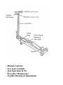
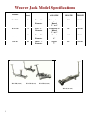
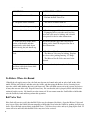
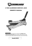
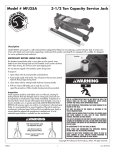
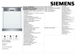
®
Weaver Jack Operation
and Service Instructions
WA-72B 2 Ton Model
WA-73B 4 Ton Model
1
WA-75B 10 Ton Model
WA-85 20 Ton Model
•
•
•
•
•
2
Manual Contents:
New Jack Assembly
Jack Operation & Use
Preventive Maintenance
Trouble Shooting & Adjustments
Weaver Jack Model Specifications
MODEL
CAP. FRONT WHEELS SADDLE STYLE
(tons)
AND SIZE
FRAME
LENGTH
JACK
WEIGHT
WA-72B
2
Two - 4"
Diameter
Triangular or
Round
5"' to 6"
51"
136 lbs
WA-73B
4
Two - 5"
Diameter
Triangular or
Round
5" to 6"
58"
212 lbs
WA-75B
10
Two - 7"
Diameter
Round
9"
66"
356 lbs
WA-85
20
Three- 7"
Diameter
Square
7"
69"
531 lbs
WA-72B (2 ton)
WA-73B (4 ton)
WA-75B (10 ton)
WA-85 (20 ton)
3
To Assemble Your New Weaver Jack
1. Check the handle set screw for tightness.
2. On the WA-85 20 Ton Jack only--Remove and discard the vent filler plug. This is very important, as the
vent hole must always be kept open so the Jack can "breathe.”. The other models have a breathable vent built
into the cap.
3. Loosen the Piston Ram and Pump Packing Nuts slightly. They are tightened all the way down at the factory
for shipment. Tighten until no oil seeps out. They only need to be moderately tight.
To Operate the Jack
WARNING: Always use stands to support vehicle before attempting under vehicle repairs or Inspections.
Always follow OSHA Workplace Safety standards.
1. Use the Jack on a smooth, hard and level surface only. Use the Jack only as a lifting device only.
2. Test the Jack by using the foot pedal only to raise the saddle to full height without a load. The pedal should
become very tight. If not, check the oil level or see the troubleshooting section.
3. The Jack is easily maneuvered by depressing the Handle Lock Lever until the lock rod engages one of the
two handle positions, and then pivoting the Jack on Its rear casters.
4. Place the jack in position so that the saddle will engage an approved lifting area of the vehicle. The saddle is
raised to the contact point by the foot pedal. Lift the load using the long handle – do not lift loads with the
foot pedal alone. On low clearance vehicles It Is often advantageous to operate the foot pedal by hand while
watches to assure proper saddle contact. Surface on which Jack rests should be fairly flat to prevent twisting of
the frame. Load should be centered in the saddle.
5. Pump with handle for easy lifting. Do not attempt to raise the jack beyond its travel stops.
6. To lower the load, pull back gently on the release lever. Always lower the load slowly.
7. Be certain that area beneath vehicle is clear before lowering the vehicle. Always use the release lever lock to
prevent unintentional operation of the release lever.
4
To Refill with Oil
Remove the filler plug and with the saddle DOWN put InAW-32 Light Hydraulic Oil (or oil that meets
MIL•F•17111 011 specifications) until the level comes up to within 1/4" to 3/8" below filler hole. Overfilling
will cause oil to spurt out the vent hole as the Jack Is lowered, or may' prevent jack from lowering properly.
Insufficient oil will cause the Jack to 11ft only part way. Always be sure to put in oil only when the saddle is
all the way down. Be careful not to let any dirt get into the reservoir while the Filler Plug Is out. Do not use
brake fluid, transmission fluid or any other fluids—doing so could damage the seals and cause jack
failure.
Overload Protection
The Lowering Valve (Release Valve) is also designed to work as an overload protection device. If you attempt
to raise a load that exceeds the jack’s rated capacity, this valve will automatically release the cylinder pressure
as an overload protection safety feature.
Safety Precautions
Follow OSHA Standards and ASME PALD Part 10 Instructions. Never exceed the Jack’s rated load capacity.
Only lift vehicles at the recommended lift points found in the vehicle’s service manual. Eye protection should
be worn per OSHA recommendations. Always use the Jack on smooth, hard and level surfaces – while
keeping the load centered on the saddle. Always check the Jack prior to each use – do not attempt to use the
Jack if any defect is observed. Do not add accessories or modify the Jack in any way. Always use Jack Stands
under the vehicle and stay clear when lifting or lowering the vehicle.
Preventive Maintenance
1. Inspect the jack before each use. Take corrective action before using the jack is a leak or defect is found.
2. Keep all working parts thoroughly lubricated. Keep Jack clean. Dirt is the major cause of Jack failure, and
all openings should be kept free of debris.
3. Packing nuts at the piston and pump plunger should be kept moderately tight. These Packings are NOT
under high pressure, and should only be tight enough to prevent leakage.
4. Keep oil filled to within 1/4” to 3/8” of fill opening. Replace oil at least once a year.
5. Ball Valve may be removed for Inspection and cleaning by removing the Ball Chamber Plug [V] and using
a small magnet, remove the balls [X&Z] and the ball weight[Y]. See Diagram
IMPORTANT: Whenever it is necessary to loosen or remove the Ball Chamber Plug, the Gasket [W] should
be replaced with a new one. Oil leakage at this point is usually caused by trying to reuse an old gasket over
again.
5
Troubleshooting
SYMPTOMS
CORRECTIVE ACTION
1. Jack will not raise saddle.
1. Check the oil level.
2. Perform the Ball Valve Test
2. Oil spurts out the vent hole.
1. The jack is overfilled with oil.
3. Jack will only lift part way up.
1. It may be low on oil. Check and refill.
4. Jack will not lift a load.
1. Check for proper oil level.
2. If pumping falls to raise the rated load, the
lower ball valve may be leaking, and it should
be inspected for dirt or other obstructions.
5. If the load rises on the down
stroke of the handle and then
immediately settles back down
while forcing the jack handle up.
This means that the upper ball valve may be
leaking, and it should be inspected for dirt or
other obstructions.
6. Jack bleeds down while under
load.
1. The Release Handle may not be closed
2. The Release Valve may be leaking. Replace
the release valve packing housing “O” Rings.
3. The Release Needle Valve may need to be
adjusted.
7. Jack only rises on half-stroke,
and then settles back down while
forcing the handle up.
This means that the jack may be Air Bound.
To Relieve When Air-Bound
1.Should the oil supply run too low, the Jack may become air-bound and work on only a half stroke of the
handle. Fill the jack with oil, and then raise the saddle, and then using the Release Lever (lowering lever)
lower the saddle while holding the fool pedal depressed. This will flush out any air in the system, and excess
oil may then run out of the vent. Repeat if necessary. Be sure that the jack is properly filled with oil before
putting it back in service. Oil should cover the piston rod. If you cannot pump the Jack Saddle to full height,
raise the Saddle by hand and then perform this operation
Ball Valve Test.
If the Jack will not raise at all, then the Ball Valve may be obstructed by debris. Open the Release Valve and
keep it open. Raise the Saddle lift arm manually to full height. Now lower the Saddle by pushing it all the way
down – this will flush out any debris in the Ball Seats. Close the release valve and try to pump up the Jack. If
it now will raise and hold, then the Ball Valve may need to be serviced.
6
Release Valve Group (upper )
- Pump Assembly (lower)
Release Valve Group and Ball Valve
Assembly Derail
Ball Valve Replacement
Ball Valve Replacement:
1. Remove the Ball Chamber Plug [V]. Remove the Two Balls [X&Z] and the Ball weight [Y].
2. Reassemble with the two new Balls [X&Z], New Plug Gasket [W] and Ball Weight [Y] (reuse the existing
Ball weight). Ball Weight is installed between the two balls.
IMPORTANT: Whenever it is necessary to loosen or remove the Ball Chamber Plug, the Gasket [W] should
be replaced with a new one. Oil leakage at this point is usually caused by trying to reuse an old gasket over
again.
7
Release Group - Needle Valve
Adjustment
Release Group Needle Valve Adjustment:
In the release group assembly, the spring governs the load that the Jack will lift. When the pressure within the
cylinder overcomes the spring tension then the release valve floats off the seat. It is Imperative that the release
valve floats freely in the release group assembly. To check- use your forefinger and thumb to grasp the release
valve where the release clevis pin passes thru, and wiggle from side to side. There should be a minimum of
.002 to.004 clearance in the Release Vale Guide [OO]. If no movement is noted, follow these steps:
Refer to the above Diagram.
Measure accurately the distance from the Bracket [O] to the first Nut [P] on the compression spring. Write
this measurement down. (This is approximately 2 inches)
Remove Nuts [P] & [Q], the Spring, the Valve Rod [N] and the Valve Guide [OO]. It is not necessary to
loosen the Packing Nut.
Next, insert the Valve Rod [N] thru the Bracket’s [O] opening, slide the Release Valve Guide [OO] onto the
rod, but not seated in the hole, and insert the rod [N] into the Packing Nut’s [R] opening.
Gently Tap the end of the release rod [N] with a hammer until it stays firmly seated in the internal needle seat.
Slide the Release Valve Guide [OO] towards the Bracket [O] (normally it will smoothly fit into the bracket
hole) and then noting where the center alignment of the rod in the bracket hole is off -- Tap the welded bracket
accordingly with a hammer to gently bend the bracket and correct the misalignment. It is in alignment when
you can smoothly slide the Valve Guide into the Bracket’s hole.
Reassemble the Release Valve and parts. Tighten the adjusting nut [P] to the original dimension that you
wrote down and lock this nut with Nut [Q] and then test the Jack for proper operation.
Seal Kits for Weaver Jacks are available from Castle Equipment Company.. TIP – It is best to order the
complete kit initially, rather than order individual parts, as it usually turns out that you will need multiple, if
not all the parts in the Kit. You will end up saving money, as individual part prices will exceed the kit cost,
not to mention that you would incur additional shipping costs.
8