1
ver.2009_03
Page 1/215
SER
Table of Content
1. GENERAL INFORMATION............................................................................. 6
1.1
Introduction…………………………………………………...……………. 7
1.2
Service quidelines……………………………………….………………… 9
1.2.1 Safety Warnings............................................................................... 9
1.2.2 Service Tools.................................................................................. 10
1.2.3 Operating materials........................................................................ 12
1.2.4 Engine Break-In.............................................................................. 13
1.2.5 Operating the engine on vehicle outside of water ......................... 13
1.3
Unit identification………………….…………………….……………...… 14
1.3.1 HSR-BENELLI Personal Watercraft Identification Numbers…...… 14
1.3.2 VIN number………………….……………………….…………...…… 14
1.3.3 Engine number ………….……………………….…………………… 14
1.3.4 Three stars – ultra low emission ……………………………….…… 15
1.3.5 Safety instructions ……………………………………………….…… 15
1.4
General specifications..........................................................................16
1.4.1 General data.................................................................................. 16
1.4.2 Standard Torque Specifications..................................................... 17
1.4.3 Convertion Chart ........................................................................... 18
2. MAINTENANCE ........................................................................................... 19
2.1
Flushing system attachment ............................................................. 21
2.2
Periodic maintenance chart ............................................................... 22
2.3
Periodic maintenance procedures .................................................... 23
2.3.1 Oil level check................................................................................ 23
2.3.2 Engine oil and filter replacement................................................... 24
2.3.3 Spark plugs replacement............................................................... 25
2.3.4 Valve clearance inspection............................................................ 26
2.3.5 Valve clearance adjustment........................................................... 27
2.3.6 Refilling of coolant.......................................................................... 31
verfdf
ver.2009_03
Page 2/215
3. ENGINE.......................................................................................................... 32
3.1
Engine Removal and Installation........................................................ 33
3.2
Engine Disassembly/Assembly.......................................................... 41
3.2.1 CYLINDER HEAD ......................................................................... 41
3.2.2 CYLINDER AND PISTONS .......................................................... 58
3.2.3 ENGINE BOTTOM END ............................................................... 66
3.2.4 Cooling system Thermostat and Water pump .............................. 82
4. TRANSMISSION............................................................................................ 91
4.1
Transmission Dismantling.................................................................. 92
4.2
Transmission Assembling.................................................................. 98
4.3
Center flange bearing........................................................................ 107
5. PUMP........................................................................................................... 109
5.1
Jet Pump overview ............................................................................ 110
5.2
JET PUMP DISASSEMBLING ........................................................... 111
5.3
ASSEMBLING THE JET PUMP ......................................................... 116
5.4
Jet Pump Assembly into the PWC ................................................... 127
5.5
Assembly of the Reverse Gear (For Series – R Pro Model only)... 129
5.6
Assembling riding plate ................................................................... 130
5.7
Steering cable setting ...................................................................... 130
5.8
Trim system bleeding ....................................................................... 131
6. FUEL SYSTEM............................................................................................ 133
6.1
Fuel Tank and Fuel Pump ................................................................ 134
7. EXHAUST SYSTEM..................................................................................... 138
7.1
Muffler and Hoses ............................................................................. 139
7.2
Exhaust Manifold .............................................................................. 141
7.3
Assembling the hoses on exhaust manifold……………………….. 144
7.4
Leak test of the Exhaust hose ......................................................... 145
7.5
Assembling the exhaust manifold on the engine ……………….… 146
ver.2009_03
Page 3/215
8. COOLING SYSTEM..................................................................................... 147
8.1
Closed circuit cooling system ......................................................... 148
8.2
Opened circuit cooling systems ...................................................... 150
8.2.1 Exhaust cooling system ............................................................... 153
8.2.2 Oil cooling system ....................................................................... 156
9. STEERING SYSTEM ................................................................................... 157
SERIES-R STEERING SYSTEM
9.1
9.2
9.3
9.4
9.5
9.6
Steering Support Assembly ............................................................ 158
Assembly of the Steering Support on the PWC ............................. 160
Handle Bar assembly ........................................................................ 161
SERIES-S STEERING SYSTEM
Handle Pole Assembly ..................................................................... 164
Handle Bar Assembly ....................................................................... 170
Assembly of the Hanle Bar on the PWC ......................................... 171
10. HULL ........................................................................................................... 177
10.1 Dashboard cover ............................................................................... 178
10.2 Drainagebox ...................................................................................... 180
10.3 Baggage Cover .................................................................................. 181
10.4 Side Cover Assembling .................................................................... 184
10.5 Sponsons assembling ...................................................................... 185
11. ELECTRICAL SYSTEM .............................................................................. 186
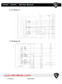
11.1 General view (SERIES-S wiring diagram) ....................................... 187
11.1.1 Sector A ....................................................................................... 188
11.1.2 Sector B ....................................................................................... 188
11.1.3 Sector C ....................................................................................... 189
11.1.4 Sector D ....................................................................................... 189
11.1.5 Sector E ....................................................................................... 190
11.1.6 Sector F ....................................................................................... 190
11.1.7 Sector G ...................................................................................... 191
11.1.8 Sector H ....................................................................................... 191
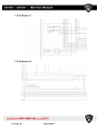
11.2 General view (SERIES-R wiring diagram) ....................................... 192
11.2.1 Sector A ....................................................................................... 193
11.2.2 Sector B ....................................................................................... 193
ver.2009_03
Page 4/215
11.2.3 Sector C ....................................................................................... 194
11.2.4 Sector D ....................................................................................... 194
11.2.5 Sector E ....................................................................................... 195
11.2.6 Sector F ....................................................................................... 195
11.2.7 Sector G ...................................................................................... 196
11.2.8 Sector H ....................................................................................... 196
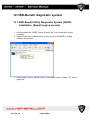
12. HSR-BENELLI DIAGNOSTIC SYSTEM ..................................................... 197
12.1
12.2
12.3
12.4
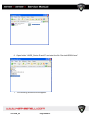
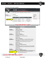
HSR-Benelli Utility Diagnostic System (HUDS) installation .......... 198
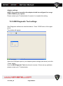
HSR Diagnostic Tool settings .......................................................... 204
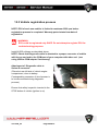
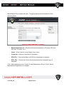
Vehicle registration process ............................................................ 205
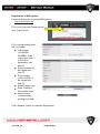
Periodic maintenance registration process ................................... 208
13. STORAGE ................................................................................................... 212
14. APPENDIX .................................................................................................. 214
ver.2009_03
Page 5/215
ver.2009_03
Page 6/215
1. General Information
1.1 Introduction
This manual contains an introductory description of the HSR-Benelli Series-R and
Series-S
Personal Water
Craft
(PWC) together with
the
procedures for
control/intervention and revision of the main components. It is designed primarily for
use by trained mechanics in a properly equipped workshop. A basic knowledge of
mechanics, the proper use of tools, and workshop procedures must be understood in
order to carry out maintenance and repair satisfactorily. All adjustments,
maintenance, and repair should be carried out only by qualified mechanics in
accordance with this service manual.
* The present manual has been prepared on the basis of state-of-the-art specifications valid at the
date of publication. In the case of modifications carried out after this date, differences may exist
between the contents of the manual and the PWC under review.
* The illustrations in this manual are used to highlight the fundamental principles and procedures of
basic interventions. They may not show exactly the PWC in your possession.
SYMBOLS
Whenever you see these ATTENTION symbols, heed their instructions!
Always follow safe operating and maintenance practices.
ver.2009_03
Page 7/215
ver.2009_03
Page 8/215
1.2 Service guidelines
1.2.1 Safety Warnings
ATTENTION:
Clean inside and outside of watercraft prior to servicing.
Clean all parts before installing.
Always use a service apron to prevent damage to foot well and top-deck fiberglass.
Watch for sharp edges which can cause personal injury.
Protect hands and arms when working with sharp components.
Always use a soft-faced hammer and extreme care when removing difficult or stuck
components.
Some fasteners are installed with locking agents or lubricants. Use of impact drivers will aid
in fastener removal.
Always follow torques specifications located throughout manual.
Fasteners secured with either too little or too much torque may fail and cause severe
property damage, injury or death.
Always follow torque sequence patterns when founding this manual.
Tighten each fastener evenly and to the specified torque value, and with specified locking
agent.
Always use new gaskets, o- rings and seals, clips, cir- clips, and snap rings when
assembling components.
Never reuse self-locking nuts when assembling components.
Never reuse hose clamps when removed from fuel lines. Replace with small gear clamps.
WARNING:
Always use HSR-Benelli authorized lubricants, greases, and locking agents when
assembling components. Failure to do so may cause severe engine or vehicle damage.
Always disconnect the black (-) negative cable first from the battery when removing the
battery. When installing the battery, attach the red (+) positive cable first, then the black (-)
negative cable.
Wear appropriate clothing, eye protection, and rubber gloves when working with batteries.
Battery acid contains sulphuric acid and is extremely poisonous. Serious burns can result
when in contact with skin, clothing, eyes or internal body components. If battery acid is
ingested, drink large quantities of water or milk. Follow with milk of magnesia, beaten egg or
vegetable oil. Call a physician immediately. Flush eyes for 15 minutes with water and seek
ver.2009_03
Page 9/215
prompt medical attention if acid comes in contact with eyes. Thoroughly wash affected
external body parts that come in contact with battery acid with water.
Keep hands, arms, legs, feet and hair away from rotating parts, hot engine and exhaust
components, drive pump and impeller and engine induction when engine is running.
Never attempt engine or driveline inspections and/or repairs without first removing lanyard
and battery cables.
Gasoline is highly flammable and explosive under certain conditions.
Always exercise extreme care when handling gasoline.
Do not smoke or allow open flames in or near the area where refuelling is performed or
where gasoline is stored.
Always refuel the watercraft outdoors and in a well ventilated area.
Do not fill the tank to the fuel cap.
If you get gasoline or oil on your skin or clothing, wash it off immediately with soap and water
and change clothing.
The engine exhaust from this product contains chemicals known to cause cancer, birth
defects or other reproductive harm.
Only run engine outdoors or in a well ventilated area.
Never run the engine for more than 10 seconds without cooling water supply.
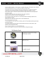
1.2.2 Service Tools
HSR-BENELLI DIAGNOSTIC SYSTEM
(Benelli engine version)
IMPELLER TOOL
FLYWHEEL PULLER
ver.2009_03
Page 10/215
T.D.C. MEASURER
TRANSMISSION GEAR PULLER
GEAR NUT REMOVAL TOOL
COUPLER REMOVING TOOL
VALVE OIL SEAL REMOVING TOOL
OIL REMOVING TOOL
ver.2009_03
Page 11/215
1.2.3 Operating materials
WARNING:
Using of not recommended operating materials causes
damage to the engine and voiding of the warranty.
Fuel
- Super petrol unleaded DIN 51607, Octane between 95 and 98 ROZ/85 MOZ.
- US premium Unleaded gasoline (91/92/93 Octane) or 95/98 ROZ ISO 5146.
In case of emergency, unleaded fuel with 91 ROZ [RON] or 82.5 MOZ [MON] may be used
for a short time.
ATTENTION:
Lower-quality fuels could only be used in case of
emergency. If used regularly, they cause decreases in
performance and possibly damage to the engine.
Recommended lubricants
LUBRICANT
SPECIFICATIONS
Engine Oil
specification
HSR-Benelli engine oil 10w60,
ACEA, A3/B3/B4, API SL
Engine Oil
Filling volumes
ver.2009_03
Series-S
Series-R
Initial filling (completely dry system)
2,3 litres
2,7 litres
Oil change without changing filter
1,7 litres
2,1 litres
Oil change with filter
2,0 litres
2,4 litres
Page 12/215
LUBRICANT
SPECIFICATIONS
Transmission oil
Lubricated by Engine oil
system - HSR-Benelli engine oil
10w60, ACEA, A3/B3/B4, API
SL
Coolant
Permanent type of antifreeze
based on monoethylene glycol,
GREEN, freezing point < -38°C
Trim system liquid
Series-S
Series-R
see engine
oil volumes
see engine
oil volumes
Total
amount:
2,5 litres
Total
amount:
3,0 litres
Brake fluid DOT4
1.2.4 Engine Brake-In
WARNING:
HSR-BENELLI recommends not to operate the engine over
6,000 r/min [RPM] during first five hours of operation. This
protective braking-in has a positive effect on the engine„s
lifespan.
1.2.5 Operating the engine on vehicle outside of water
WARNING:
If PWC is outside of water its engine may be operated at idle
speed only for maximum of 30 seconds. Never run the
engine for more than 30 seconds without cooling water
supply.
If it is necessary to operate the engine longer than 30 seconds on vehicle out of water, the
flushing equipment must be used.
Use flushing system to operate vehicle out of water
An auxiliary cooling supply may be used if the watercraft cannot be operated in water during
adjustments.
If possible, always operate the watercraft in water rather than use an auxiliary cooling supply.
See chapter Maintenance – Flushing system connection.
ver.2009_03
Page 13/215
1.3 Unit identification
1.3.1 HSR-BENELLI Personal Watercraft Identification
Numbers
The engine Serial number and VIN number are used to register the watercraft. They are
unique numbers that distinguish each watercraft from others of the same model.
If the watercraft is ever stolen these numbers will help identify it. The owner should keep a
record of these numbers in a place other than the watercraft
1.3.2 VIN number
AT : Manufacturing Country
HSR : HSR-BENELLI
A: Model Code
1001: Sequential Serial Numbers
Production Month: C (Month code)
Production Year : 8
Model Year : 08 (Model year : 8 = 2008)
You will find the serial number at the right rear side of your PWC
1.3.3 Engine number
Number is beside the starter motor.
Engine Number:
BH33
Engine Type
000001
Serial Number
JJ808
Model and Year Code
ver.2009_03
Page 14/215
1.3.4 Three stars – ultra low emission
The three-star label identifies engines that meet the Air Resources
Board’s Personal Watercraft and Outboard marine engine 2008
exhaust emission standards. Engines meeting these standards have
65% lower emissions than One Star – Low Emission Engines.
1.3.5 Safety instructions
For Series-S ONLY
Safety Instructions sticker is placed under the handle pole on
the Series-S models.
For Series-R ONLY
Safety Instructions sticker is placed on the Luggage Cover on
the Series-R
ver.2009_03
Page 15/215
1.4 General specifications
1.4.1 General data
2009 HSR-BENELLI
Series – S
Length: ..........…………….. 2,32 m
Width:……………………..
0,70 m
Height:……………………. 0,67 m
Dry Weight:………………. 168kg
Category: …………………. Stand-up
Riders:…………………….. 1 person
Fuel Capacity: 18 litres 4, 75 US Gal
Series - R
Length: ..........………. 3,23m
Width:………………… 1,20 m
Height:……………….. 1,03 m
Dry Weight:………….. 263 kg
Category: ……………. Runabout
Riders:………………….1 – 3 persons
Fuel Capacity: 70 litres 18,47 US Gal
Emission Certification: Three Star - Ultra Low Emission
ENGINE
EMISSION CONTROL SYSTEM
FUEL
SFI ( Sequential Fuel Injection )
Recommended fuel:
- Super petrol unleaded DIN 51607, Octane between 95
and 98 ROZ/85 MOZ.
- US premium Unleaded gasoline (91/92/93 Octane) or
95/98 ROZ ISO 5146.
SPARK PLUG
SPARK PLUG GAP
ENGINE DISPLACEMENT
NUMBER OF CYLINDER
CYLINDER LINING SURFACE
BORE x STROKE
COMPRESSION RATIO
CYLINDER COMPRESSION
MAXIMUM HORSEPOWER
COOLING SYSTEM
THERMOSTAT
EXHAUST OVERHEATING WARNING
COOLANT OVERHEATING WARNING
ENGINE LUBRICATION SYSTEM
ENGINE OIL SPECIFICATIONS
ver.2009_03
CHAMPION RG4HC
0,75 – 0,8 mm ( 0.0028 – 0.032 in.)
1130 cc
3
Nicasil
88 x 62 mm
12 -13:1
9,6 +/- 1 bar ( 140 +/- 14,5 psi )
Series-S Pro Edition - 142 hp,
Series-S Race Edition - 162 hp,
Series-R Naked Edition - 142 hp,
Series-R Pro Edition - 172 hp
- closed loop with thermostat;
- auxiliary opened loop oil & exhaust cooling systems
70°C
Exhaust Manifold Overheat switch – engine limiter
activation
Cooling manifold Sensor – 90° engine limiter activation
Wet Sump
HSR-BENELLI Engine oil 10w60,
ACEA, A3/B3/B4, API SL
Page 16/215
RPM LIMITER
EXHAUST SYSTEM
ENGINE MANAGEMENT SYSTEM
FUEL DELIVERY
IDLE SPEED
MAGNETO GENERATOR OUTPUT
BATTERY
FUSES
STARTER
PROPULSION
JET PUMP TYPE
IMPELLER
COUPLING TYPE
MINIMUM DEPH FOR OPERATION
HULL / BODY
HULL MATERIAL
9200 – 9300 1/min – Determined by ECU
Waterbox with water injector
WALBRO Multi-point fuel injection
1700 1/min +/- 50
13.5V / 48A at 5000 rpm
Series-R: 12 Volts 20Ah
Series-S: 12 Volts 14Ah
30A – Alternator, 15A – Fuel Pump, 7,5A – Stop switch,
30A - Main
Electric Motor 12V – 850 W
SOLAS – Axial Flow – 12 Veins – Steel stator
Stainless steel – 3 blade
Series-S Pro Edition – 14/25,
Series-S Race Edition – 15/26,
Series-R Naked Edition – 11/19,
Series-R Pro Edition – 11/19 XL
Six piece coupler + Damper
60cm (2 Ft)
Fiberglass, RTM Process
1.4.2 Standard Torque Specifications
The following torque specifications are to be used as a general guideline.
Use standard torque values for the appropriate size fastener when torque values are not
specified.
Always consult the specific manual section for torque values of fasteners and use of
locking agent.
RECOMMENDED TORQUE SPECIFICATION
STAINLESS STEEL FASTENERS (METRIC)
4 mm
3 -3,5 NM (40–42 in.lbs.)
ver.2009_03
5 mm
4 – 4,5 NM (45-52 in.lbs.)
6 mm
5,5 – 6,5 NM (66-78 in.lbs.)
7 mm
17 – 23 NM (13-16 ft.lbs.)
10 mm
35 – 40 NM (26-30 ft.lbs.)
12 mm
54 – 60 NM (40-44 ft.lbs.)
Page 17/215
1.4.3 Convertion Chart
ft. lbs.
x 12
= in. lbs.
in. lbs.
x 0,0833
= ft. lbs.
ft. lbs.
x 1,356
= Nm
in. lbs.
x 0,115
= kg-m
Nm
x 0,7376
= ft. lbs.
kg-m
x 7,233
= ft. lbs.
kg-m
x 86,796
= in. lbs.
kg-m
x 10
= Nm
in.
x 25,4
= mm
mm
x 0,03937
= in.
in.
x 2,54
= cm
mile (mi.)
x 1,6
= km
Km
x 0,6214
= mile (mi.)
Ounces (oz.)
x 28,35
= Grams (g)
Grams (g)
x 0,035
= Ounces (oz.)
lb.
x 0,454
= kg
kg
Cubic inches (cu in)
x 2,2046
= lb.
x 16,387
= Cubic centimeters (cc)
Cubic centimeters (cc)
x 0,061
= Cubic inches ( cu in)
Imperial pints (Imp pt)
x 0,568
= liters (l)
Liters (l)
x 1,76
= Imperial pints (imp pt)
Imperial quarts (Imp qt.)
x 1,137
= liters (l)
Liters (l)
x 0,88
= Imperial quarts (Imp qt)
Imperial quarts (Imp qt.)
x 1,201
= US quarts (US qt)
Liters (l)
x 1,057
= US quarts ( US qt)
US gallons (US gal)
x 3,785
= Liters (l)
Liters (l)
x 0,264
= US gallons (US gal)
Pounds – force per square inch
x 6,895
= Kilopascals (kPa)
Kilopascals (kPa)
Kilopascals (kPa)
x 0,145
= Pounds – force per square inch (psi)
x 0,01
= Kilograms- force per square cm
Kilograms- force per square cm
x 98,1
= Kilopascals (kPa)
(psi)
C to F: 9 ( C + 40) 5 - 40 = F
ver.2009_03
Page 18/215
F to C: 5 ( F + 40) 9 - 40 = C
ver.2009_03
Page 19/215
2
Maintenance
The table in chapter
Periodic maintenance table
provides the manufacturer’s
recommended intervals for maintenance work. Following the maintenance recommendations,
a long life span of the vehicle can be achieved and unnecessary environmental damage
prevented. The Maintenance intervals specified in the table should not be exceeded by more
than 10%.
All activities described in this manual must be carried out by trained service staff.
In case of warranty repairs HSR-BENELLI reserves the right to request warranty approval
documents for performed periodic maintenance of eligible PWC.
ATTENTION:
The vehicle owner or user is responsible adhering to the
maintenance intervals. HSR assumes no liability for damage
that arises due to maintenance not carried out.
ver.2009_03
Page 20/215
2.1 Flushing system attachment
For service purposes engine of vehicle could be started out of water using Flushing system
to provide cooling by tap water.
ATTENTION:
Engine could be operated only at idle rpm even if flushing kit is
attached. Do not run engine when flushing kit is attached
continuously for a period over 5 miutes to prevent overheating.
Flushing system hose (Series-R, LEFT SIDE)
Flushing system hose (Series-S, RIGHT SIDE)
ver.2009_03
Page 21/215
Flushing system fitting
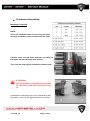
2.2 Periodic maintenance chart
Jobs to be performed
Visual Check of all hoses,
pipes, hose clips,
Visual Check of all nuts,
bolts and fixing elements
Change oil and oil filter
Lubricate throttle housing
cable connection
Lubricate steering pivot
(dismantle)
Check valve clearance and
adjust in necessary
Check clean Flame Arrestor
Check / tighten engine
mount bolts
Check valve for fuel
ventilation
Check throttle operation
system
Check and clean jet pump
(including cooling system
sieve)
Check / renew drive damper
Check steering and lanyard
operation
Replace rubber duckbills if
necessary (Series-S only)
Check and grease Battery
clamps
Check/ adjust TPS
Check impeller torque 100
Nm
Replace Pump Seal, check
Pump Bearing / replace if
necessary
Change Spark plugs
Check free play of the
damper coupler and replace
if necessary
Check the transmission oil
line banjo bolts for tightness
Replace inline Filter in the
exhaust cooling (water
injection) system
ver.2009_03
After the
first 10
hours of
operation
At 25 h of
operation
At 50 h of
operation
At 75 h of
operation
At 100 h
of
operation
Each
additional
25 h
Each
additional
100 h
x
x
x
x
x
x
x
x
x
x
x
x
x
x
x
x
x
x
x
x
x
x
x
x
x
x
x
x
x
x
x
x
x
x
x
x
x
x
x
x
x
x
x
x
x
x
x
x
x
x
x
x
x
x
x
x
x
x
x
x
x
x
x
x
x
x
x
x
x
x
x
x
x
x
x
x
x
x
x
x
x
x
x
x
x
x
x
x
x
x
x
x
x
x
x
x
x
x
x
x
x
x
x
x
x
x
x
x
x
x
x
x
x
x
x
x
x
x
x
x
x
x
x
x
x
x
x
x
x
x
x
x
x
x
x
x
x
Page 22/215
2.3 Periodic maintenance procedures
2.3.1 Oil level check
NOTE:
Use a clean, lint-free cloth
PWC must be leveled to perform oil level verification. Check
the oil level when engine is cold by pulling the oil dipstick out
of the engine. The oil level must be within the minimum and
maximum marks. When engine is warm proceed the same
way but insure your check is done five minutes after engine is
stopped to enable the remaining oil to go back to the bottom
of the engine. Oil level may be higher than at cold engine
since the oil volume increases in warm condition.
WARNING:
Engine oil may be hot.
Note: Engine must be cold
If the valve clearance is out of specifications take note about
your current reading for adjustment.
ver.2009_03
Page 23/215
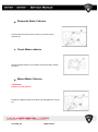
2.3.2 Engine oil and filter replacement
Remove the dipstick.
To suck the oil out with an oil removing pump, put the suction
hose as deep as possible into the engine into dipstick tube.
Suck the oil out of the engine completely.
Take out old oil filter
Before installation of new oil filter, grease filter O-ring slightly
with engine oil.
Install new oil filter and tighten with specified tightening torque.
Open oil filling cap on engine valve cover (shown by arrow).
Refill the engine with new engine oil.
ATTENTION:
ALWAYS USE HSR-BENELLI ENGINE OIL.
NOTE: FOR SERIES-S
Volumes of oil in the engine: min 1,7 litres (without change of oil filter), max 2,0 litres
(change of oil filter included). In case of completely dry engine: 2,3 litres.
Required torque for oil filter cover: 24 Nm
Required torque for ignition coils: 10 Nm
Required torque for spark plugs: 12 Nm
WARNING:
Never fill with more than 2,3 l of oil into the engine (oil filter included).
NOTE: FOR SERIES-R
Volumes of oil in the engine: min 2,1 litres (without change of oil filter), max 2,4 litres
(change of oil filter included). In case of completely dry engine: 2,7 litres.
Required torque for oil filter cover: 24 Nm
Required torque for ignition coils: 10 Nm
Required torque for spark plugs: 12 Nm
WARNING:
Never fill with more than 2,7 l of oil into the engine (oil filter included).
ver.2009_03
Page 24/215
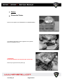
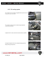
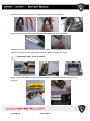
2.3.3 Spark plugs replacement
ATTENTION:
Replace spark plugs only when engine is COLD. In other case there is a risk to
damage cylinder head thread. Use only spark plugs of recommended type in
order to avoid engine damage.
NOTE: RECOMMENDED SPARK PLUGS
CHAMPION RG4HC
Replace engine spark plugs every 100 hrs. Check electrode gap and spark plug condition
after the break-in period (10-12hrs).
1 Unscrew nut A
2. Remove ignition plate B
3. Remove ignition coil C
4. Unscrew spark plug
To reinstall:
Follow the procedure exactly in the opposite way.
WARNING:
Do not tighten spark plugs with torque over 12Nm not to damage cylinder head
thread.
Electrode gap spark plug: 0,75 – 0,80 mm
ver.2009_03
Page 25/215
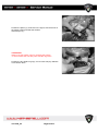
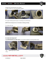
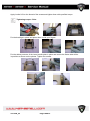
2.3.4 Valve clearance inspection
ATTENTION:
Valve clearance must be checked and
adjusted when the engine is cold (room
temperature)
Remove cylinder head cover to access cylinder head
(See Head cover Removal)
Taking the engines cylinder 1 to the TDC verify that also
the marks and of the Camshaft sprockets are aligned
between them and with the head plain.
Measure the clearance between camshaft and valve cap
by a thickness gauge making sure that the clearance is
in the specific range.
Start from measuring clearance on:
Cylinder 2 EXHAUST valves;
Cylinder 3 INTAKE valves
Proceed the measurement for other valves, rotating the
engine using a wrench on a special nut of camshaft
(measure the clearance when the cams corresponding to
eligible valves are in upwards position):
Cylinder 1 EXHAUST valves;
Cylinder 2 INTAKE valves
and
Cylinder 3 EXHAUST valves;
Cylinder 1 INTAKE valves
ver.2009_03
Page 26/215
SPECIFIC VALUE
Intake = 0.30 ~ 0.35 mm
Exhaust = 0.35 ~ 0.40 mm
Note: Engine must be cold
If the valve clearance is out of specifications take note about your current reading for
adjustment.
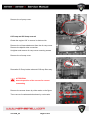
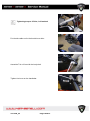
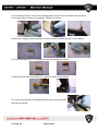
2.3.5 Valve clearance adjustment
ATTENTION:
To prevent falling of removed parts into
crankcase please use proper sealing material
at timing chain drive casing.
Remove the chain pad (6), unscrewing the two fixing
screws (7).
ver.2009_03
Page 27/215
ATTENTION:
Make sure that the distribution chain does not
fall into the casing.
Remove the chain tensioner.
ATTENTION:
Mark the removed elements for correct
reassembling (cylinder number, camshaft
IN/EX, etc).
Remove mounting screws of camshaft holders (8) and
remove them. Take care of removing metal bushings of
each holder.
Remove the bridge (9), unscrewing the fixing screws.
Raise the camshaft paying attention to keep all teeth of
the timing chain in place, allowing the removal of the valve
caps (1).
ver.2009_03
Page 28/215
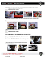
Remove the cap (2) of the valve which requires
adjustment using a magnet. To change the valve
clearance, replace the shim with one of a different
thickness. Measure the thickness of the removed shim.
NOTE:
Mark and record the locations of the valve caps and
shims so that they can be reinstalled in their original
positions.
Valve clearance calculation:
In order to set a proper valve clearance, please follow the points below:
1. Measure the clearance of each individual valve and make note about this reading (at
cold engine).
2. Check the present shim size.
3. Calculate the thickness of the replacement shim.
Example: your reading on the intake valve is 0,27mm (spec. 0.30 ~ 0,35mm)
Clearance is less than specified. The shims are available in 0,025 mm steps of thickness.
Present shim gives 0,27mm clearance with its thickness 2,350 mm.
Shim size calculation:
Present clearance: 0,27mm. 0,30 ~ 0,35mm needs to be achieved by reducing shim size.
Using of 2 size thinner shim 2,300mm (=2,350mm – 2x0,025mm) increases the valves
clearance: 0,27mm+2x0,025mm=0,32mm. The result meets specified range.
The present 2,350mm shim is to be replaced by 2,300mm shim.
4. Assemble the removed pats of cylinder head (see Camshaft installation above),
tighten the fasteners according to given specifications.
5. Remeasure the valve clearance and readjust if necessary.
ver.2009_03
Page 29/215
Installing Cylinder Head cover
ATTENTION:
Always use new gaskets.
Position the gaskets of the head cover (1 and 2 ).
ATTENTION:
Make sure that gaskets (2) do not fall into the
head during cover installation.
*Apply THREEBOND® paste as shown on the drawing.
Install the cylinder head cover and insert rubber
bushings and the screws (3) and (4) as shown on the
figure.
NOTE:
Replace the rubber bushings of the screws (3) and
(4) during reassembly.
Tighten the head cover mounting screws to the
specific torque, take care not to cut or damage
rubber bushings.
Tightening torque: 10 N·m (1 Kg-m)
ver.2009_03
Page 30/215
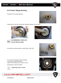
2.3.6 Refilling of coolant
WARNING:
This process is a very sensitive and requires special attention. The risk is that
air bubbles remain in the cooling system so that the heat of the engine cannot
be transferred into the radiator of the Jet Pump.
The total volume of coolant is:
for SERIES-S 2,5 litres;
for SERIES-R 3,0 litres.
1. Fill the cooling system with cooling liquid of recommended
type as much as possible.
2. Press on the coolant hoses and ensure to get a maximum of
air bubbles out of it. Add more coolant.
3. Repeat this process 2-3 times until no more coolant can be
added.
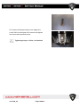
4. Do a test run in the water to heat the engine. Stop the engine
couple of times and check the anti freeze coolant level. Add
coolant if necessary.
5. Repeat this process couple of times until the thermostat has
opened and the entire amount of coolant circulates in the cooling
system.
WARNING:
If the engine is hot the Jet Pump is hot too and might be
dangerous for your health.
NOTE: Ensure the engine is fully filled with coolant after thermostat was opened.
WARNING:
Changing the battery ensure that engine is cold.
NOTE: Use only high quality coolant (See recommended lubricants)
ver.2009_03
Page 31/215
ver.2009_03
Page 32/215
3
Engine
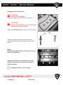
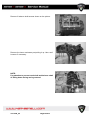
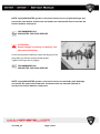
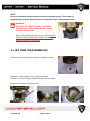
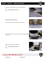
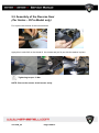
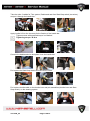
3.1 Engine Removal and Installation
The installation of the engine and engine subsystems is the reverse to their removal. During
engine installation, several important notes must be made.
Always verify the correct number of engine mounting strap shims are installed on
each engine mounting post. Remove the pump to check driveshaft alignment, add
shims to move the engine up or down to align properly.
Always verify that the engine does not interfere with critical routings such as the
steering cable, cooling hoses, and main wiring harness.
Steering cable must be fixed on front left engine mounts to avoid damage from
engine.
ver.2009_03
Page 33/215
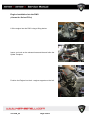
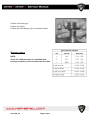
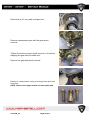
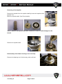
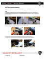
Engine installation into the PWC:
(shown for Series-R Pro)
Lift the engine into the PWC using a lifting device.
Insure you hook on the exhaust hose and the and inline the
Spider Couplers.
Position the Engine into the 4 x engine supports on the hull.
ver.2009_03
Page 34/215
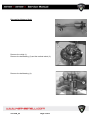
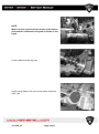
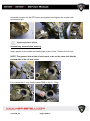
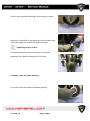
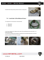
Ensure the exhaust hose and the Spider Couplets are properly
aligned.
Take a metal ruler like shown on the picture and check the
alignment of the Spider coupler to see if the engine is
positioned properly according to propulsion system.
If the engine position needs to be adjusted use special washer
with 0,5 and 1 mm thickness to align the system.
NOTE: If the engine needs to be heightened you have to
use washers on all four engine supports.
Apply blue Loctite on the screws and tighten the screws of the
engine support with specified torque.
Tightening torque: 30 N·m
ver.2009_03
Page 35/215
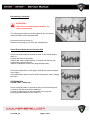
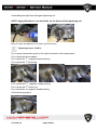
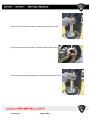
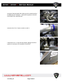
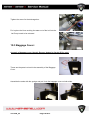
Tighten the exhaust hose with a screw driver.
Plug in the cooling hose for the 3 in 1 hose.
Plug in the water relieve hose for the 3 in 1 hose.
Plug in the water relieve hose for the exhaust manifold
Tighten the fuel hose to the fuel rail
NOTE: Take care to install the sealing rings
Plug in the cooling water supply lines as shown on the picture
into the oil cooler.
ver.2009_03
Page 36/215
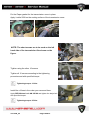
Plug in the water relieve hoses from the oil cooler.
Plug in the water supply hose for the waterpump.
Plug in the coolant hose for the temperature thermostat.
ver.2009_03
Page 37/215
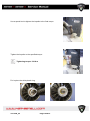
Plug in the Ignition wires for the ignition coils.
NOTE: Ignition wires are marked with numbers of
corresponding cylinders.
Plug in the wires for the injectors.
NOTE: Injector wires are marked with numbers of corresponding cylinders.
Plug in the connector for the heat sensor.
Plug in the TPS sensor.
Plug in the pick-up coil sensor.
ver.2009_03
Page 38/215
Plug in the oil pressure sensor.
Plug in the SSSA connector.
ö
Tighten the ground wire.
Connect the wires of the voltage regulator on the ignition cover.
ver.2009_03
Page 39/215
Connect the positive wire from the starter to the starter relays.
Connect the positive starter cable to the positive starter
connector.
Connect the acceleration wire to the throttle bodies.
For adjustment of the acceleration wire insure the throttles
are on open wide throttle position.
ver.2009_03
Page 40/215
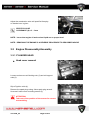
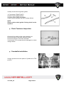
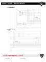
Adjust the acceleration wire until specified free play
on throttle lever is given.
SPECIFIC VALUE
CLEARANCE (A) = 2 - 3 mm
NOTE: Insure that engine oil and coolant liquid are on proper level.
NOTE: REMOVING THE ENGINE IS A REVERSE PROCEDURE TO DESCRIBED ABOVE
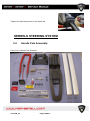
3.2 Engine Disassembly/Assembly
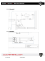
3.2.1 CYLINDER HEAD
Head cover removal
Loosen and remove self-locking nuts (3) and coil support
rods (2).
Slip off ignition coils (4).
Remove the spark plugs using 16mm spark plug wrench.
Unscrew 8 valve cover mounting screws (5)
ATTENTION:
Take note of the position of the screws for correct
reassembling.
ver.2009_03
Page 41/215
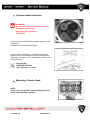
NOTE:
Replace 8 screws rubber bushings (5) during
reassembling.
Removing Camshafts
Remove the head cover.
Remove the chain pad (6),
Unscrewing the two fixing screws (7).
ATTENTION:
Make sure that the distribution chain does not fall
into the casing.
Remove the chain tensioner.
ATTENTION:
Note the position of the elements for correct
remounting.
Unscrew the fixing screws of the large caps (8) and
remove them.
Remove the bridge (9), unscrewing the fixing screws.
Remove the camshafts and the chain.
Camshafts Inspection
Check that camshafts with a micrometer, as shown on the
picture.
If the value does not enter within the specific measure,
change the element.
INTAKE SHAFT VALUE LIMIT:
A= 36.6 mm B= 27.85 mm
EXHAUST SHAFT:
A= 36.6 mm B= 27.85 mm
ver.2009_03
Page 42/215
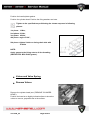
Check the deformation of the camshaft with a comparator,
as shown on the picture.
If the value does not enter within the specific measure,
change the element.
INTAKE AND EXHAUST SHAFT DIMENSIONS
LIMIT:
MAX. VALUE = 0.03 mm
The maximum play between the distribution camshaft and seat
is 0.1 mm.
If the value does enter within the specific value, change the
element.
VALUE LIMIT
CAMSHAFT AND SEAT
Max. play= 0.01 mm
Chain, Sprocket Wheels and Camshaft Chain Guide Inspection
Check the state of wear of the camshaft distribution chain
(1). If the element has blocked links, is excessively worn,
change it.
ver.2009_03
Page 43/215
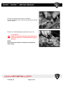
Visually check the timing chain guides:
1) Fixed guide (FRONT PART)
2) Mobile guide (REAR PART)
3) Upper guide (FIXED ON HEAD)
If one or more elements are worn, change it/them.
NOTE
Always replace chain guides if timing chain is to be
replaced.
Chain Tensioner Inspection
Check the free sliding of the chain stretcher rod.
Check the state of the chain stretcher spring.
Check the integrity of the chain stretcher.
If an element or its components are damaged or ruined,
change it/them.
Camshafts installation
Using a special tool set the piston of cylinder #1 to TDC
position.
ver.2009_03
Page 44/215
NOTE: Ensure that during assembling engine
crankshaft is not moved from 1st cylinder TDC
position and camshafts marks are aligned as shown
on the picture.
Position the exhaust shaft and the timing chain, position
the holders in their original direction (written on the
outside) and tighten the fixing screws according to the
diagram in the figure.
Tightening torque:
1st phase: 6 N·m;
2nd phase: 13 N·m
INTAKE
Position the intake shaft and the timing chain, position
the holders in their original (mark on the outside of
holder should match the number engraved on inside of
cylinder head) and tighten the fixing
screws according to the diagram in the figure.
Tightening torque:
1st phase: 6 N·m;
2nd phase: 13 N·m
ver.2009_03
Page 45/215
Position the timing chain on the camshaft sprockets.
Position the bridge and the upper chain pad and tighten the fixing screws in two phases in
shown sequence.
Tightening torque:
1st phase: 6 N·m;
2nd phase: 13 N·m
NOTE:
Always oil the sliding parts with Teflon SINTOFLON paste.
Position the chain tensioner (1) complete with O-ring (2) and
tighten two screws (6).
Tightening torque: 10 N·m
Position the rod pushing spring (3) and the washer (4) and
tighten tensoiner cap nut (5).
Tightening torque: 7 ÷ 8 N·m
ATTENTION:
Always check that chain tensioner is in
position 0 before mounting it.
Align the marks on the camshaft sprockets as shown on the
figure.
Count 30 chain pins from position 1 to position 30 as indicated
on the figure.
ver.2009_03
Page 46/215
Check that cylinder 1 cams are turned towards each other as
on the figure.
Remove Cylinder Head
Remove the chain tensioner, chain pads, camshafts
(see above).
Loosen and remove the eight nuts and washers (1)
indicated in the figure according to the shown sequence
and two screws on the right side of the engine (timing
chain side).
ver.2009_03
Page 47/215
Cylinder Head Inspection
WARNING:
Do not use a pointed instrument to avoid
damaging or scatching:
Spark plug hole threading
Valve seats
Check and eventually eliminate carbon deposits in the
combustion
chamber with a rounded-off scraper.
If the surface is damaged or scratched, change the
element. Check the distortion of the cylinder head as
indicated in the figure. If is is outside the specific value,
rectify the head.
VALUE LIMIT
HEAD DISTORTION
max. distortion = 0.2 mm
Mounting Cylinder Head
NOTE:
Always use new gaskets. Clean and degrease the
head surface and the cylinders.
ver.2009_03
Page 48/215
Position the head/cylinder gasket.
Position the cylinder head. Position the fixing washers and nuts.
Tighten to the specified torque following the shown sequence in following
phases:
1st phase: 10 Nm;
2nd phase: 30 Nm;
3rd phase: 45 Nm;
4th phase: angle of 100°;
5th phase: tighten 2 bolts on timing chain side with
10.8 Nm
NOTE:
Apply grease to the fixing nuts to oil the threading
(MOLIKOTE® BR2 PLUS grease).
Valves and Valve Spring
Remove Valves
Remove the cylinder head (see ("REMOVE CYLINDER
HEAD").
Position the head on a slightly inclined surface to show the
valves to remove, perpendicular to the surface.
ver.2009_03
Page 49/215
To remove the valves use a valve dismantling instrument (2)
with correct attachment (3), press the valve down and take off
the two semi-cones.
Loosen the clamp and remove the valve and its components
as shown on picture.
The following procedure is applied to the valves (4), the springs
(5 and 6) and relative components (7, 8 and 9).
NOTE:
Make sure that valve (4) has a perfect seal by pouring
petrol into the conduits and making sure that
there are no losses through the valves. Make sure
that the valves are perfectly sealed.
Remove the small bowls taking note of the position on each
valve and coupling them to their pads.
Free the pusher spring plate (7) using the specified instrument
to remove the two lock cones.
Remove the external spring (5), the internal spring (6), valve (4),
the valve seal ring and the lower cup.
ver.2009_03
Page 50/215
Valves and Valve Guide Inspection
The following procedure must be carried out on all valves and relative valve guides.
Check that values (A) and (B) are within the tolerance of the specific values.
If values (A) and (B) are not within the value limits, change the elements.
INTAKE VALVE DIAMETER LIMIT
A max. = 5.05 mm
B min. = 4.965 mm
EXHAUST DIMENSION LIMITS
A max. = 5.05 mm
B min. = 4.955 mm
Check condition of the surfaces of the valves.
Eliminate eventual carbon deposits.
If the surface is excessively ruined, change the element.
Check thickness (A) indicated in the figure.
VALVE THICKNESS VALUE LIMIT
A= 1,0 ÷ 1,3 mm
ver.2009_03
Page 51/215
Check the deformation of the legs of the valve.
If the concentricity value does not enter within
the margin, change the element.
VALVE REFORMATION
VALUE LIMIT
0.01 mm
Valve Seat Inspection
The following procedure must be applied to all
the valve seats. Eliminate eventual carbon deposits.
Apply the tincture of bluing (b) on the face of the valve.
Install the valve into the appropriate seat.
Press it using the guide on the seat to leave an evident
impression.
Measure the width of the seat of the valve.
NOTE:
It will be necessary to remove the bluing at the point
at which the seat and the face of the valve touch.
NOTE:
If the trace is not partial or not uniform, carry out a
ver.2009_03
Page 52/215
smoothing operation on the face and the seat of the
valve.
Smooth:
• the face of the valve
• the seat of the valve
NOTE:
After having changed the cylinder head or the valve
and the relative guide, it will be necessary to smooth
the seat and face of the valve.
Apply a coarse grained paste (a) for smoothing on the
face of the valve.
ATTENTION:
Do not allow the smoothing paste to enter into the
space between the stem of the valve and the guide.
Apply disulfide of molybdenum to the stem of the valve.
Insert the valve into the cylinder head.
Rotate the valve until its face and seat shine uniformly,
Then remove the smoothing paste.
NOTE:
To obtain optimum smoothing results, strike the seat
of the valve lightly while turning it forwards and
backwards in your hands.
Apply a fine grained paste to the face of the valve and
repeat the above operations.
Completely eliminate the smoothing paste from the face and
the seat of the valve at the end of each operation.
Apply the tincture of bluing (b) on the face of the valve.
Install the valve in the cylinder head.
Press the valve through the valve guide and on the valve
seat to leave a clear trace.
ver.2009_03
Page 53/215
Valve Spring Inspection
The following procedure is valid for all valve springs.
Measure the length (a) of the free valve.
If the value does not enter within the envisaged limits, change
the spring.
FREE VALVE SPRING LENGTH
External valve spring
Tollerance limit: 37 mm
Internal valve spring:
Tollerance limit: 34.0 mm
Bring the spring to a value length (c) and check the value of
the
load:
VALUE LIMIT
External spring length: 23.2 mm
Load value limit: 565 N
Internal spring length: 21.2 mm
Load value limit: 314 N
Check the inclination (a) of the valve spring as illustrated in
the figure.
If (a) does not enter within the specific value, change it.
VALUE LIMIT
INCLINATION SUCTION SPRING A = 2 mm
INCLINATION EXHAUST SPRING A = 2 mm
ver.2009_03
Page 54/215
Valve Caps Inspection
The following procedure must be applied to all valve caps.
Check that caps are not broken or scratched, in other case
replace them.
Mount Valve
The following procedure must be applied to all the valves and
relative components.
Oil the valve stem with the recommended oil.
RECOMMENED OIL
Disulfide of molybdenum oil
Mount the lower small cup (1).
Check that the thickness of the small cap is 1.5 mm.
ver.2009_03
Page 55/215
WARNING:
Always use new gaskets and oil seals.
Mount the rubber valve seal (2) with the appropriate pad (3).
ATTENTION:
Intake valves are larger than the exhaust valves.
Insert the valves (4).
Position the internal (5) and external (6) springs as shown in
the figure.
Insert the two lock cones (7) into the upper small cup (8).
ver.2009_03
Page 56/215
Position the small cap as shown in the figure.
Use the dismantling valve instrument making sure that the
valve is correct.
Position the calibrated pads (9) and valve caps (10).
ATTENTION
Make sure that the individual valve lifters and
the valve guide are re-mounted in the original
position.
NOTE:
Check that valve caps turn easily by rotating them
with a finger.
ver.2009_03
Page 57/215
3.2.2 Cylinder and Pistons
Dismantle Cylinder Body
Remove the cylinder head (see "REMOVE CYLINDER
HEAD").
Remove the gasket of the head, the cylinder body (1) and
the base of the cylinders gasket beneath.
Check that the walls do not present signs of seizure with the
pistons. Check the ovalisation of the cylinders
as indicated in the figure.
ATTENTION:
In the case of changing the cylinder block also
change the pistons and the elastic straps, if necessary.
The cylinder is distinguished by a letter that indicates
the class it belongs to. The cylinder-piston coupling
must be carried out among the same classes that they
belong to.
The letters are on the external front part (exhaust side) of the
cylinder.
ver.2009_03
Page 58/215
Dismantle Water Collector
Unscrew and remove the three screws (1) and remove the
collector (2).
Check Water collector
Check eventual breaks on the collector and if necessary change
the piece.
Mount Water Collector
ATTENTION:
Always use new gaskets.
Position the gasket (1)and the collector (2) and tighten the screws
(3).
ver.2009_03
Page 59/215
Piston
Dismantle Piston
Remove the cylinder (see "DISMANTLE CYLINDER BODY").
The following procedure must be applied to all 3 pistons.
Remove the elastic ring (1).
ATTENTION:
Do not use hammers for the piston pin removal (2).
Remove pin (2) and remove piston (3).
ver.2009_03
Page 60/215
Check Piston
The following procedure must also be applied to all the other
pistons.
Check eventual breaks on the piston.
Use a micrometer, as shown in the figure, to check that the
value (P) enters within the specific value.
ATTENTION:
In the case of changing one or more pistons:
The piston is distinguished by a letter that indicates the class it belongs to.
The cylinder-piston coupling must be carried out among the same classes that they belong to.
NOTE:
The maximum play of the piston is of 0.1 mm.
Change the piston if necessary.
Check Piston Rings
The following procedure must be applied to all the piston rings.
Check the absence of scuffing and traces of shrinkage on every
Piston ring.
Check that the edge of the section is well defined and free in the
housings.
Whenever wear in the segments is found, change the pistons
as well.
ver.2009_03
Page 61/215
Piston Ring Play
Measure the lateral play of the 1st and 2nd segment using a feeler.
If one of the two plays exceeds the limit specified, change both
the piston and the segments.
PISTON RING PLAY
SERVICE LIMIT:(1st): 0.20 mm
(2nd): 0.18 mm
PISTON RING WIDTH
STANDARD:(1st ): 1.02 – 1.04 mm
(2nd): 1.01 – 1.03 mm
(OIL RING): 2.01-2.03
PISTON RING THICKNESS
STANDARD:(1st): 0.97 – 0.99 mm
(2nd): 0.97-0.99 mm
Check Piston Pin
The following procedure must be applied to all the piston pins.
Check that value (a) enters within the specific value.
NOMINAL VALUE
a = 18,995 ÷ 19,000 mm
ver.2009_03
Page 62/215
Check the value of (b).
NOMINAL VALUE
b = 19,002 ÷ 19,008 mm
NOTE:
If the play between the piston pin and the pin is
more than 0.03 mm, change the piston.
Mounting Piston Rings:
nd
Install the piston rings in the order: oil ring , 2 piston ring
, 1st piston rings.
The first element to insert into the slot of the oil ring
is the spacer (1). After having positioned the spacer, insert its
lateral rings (2).
NOTE:
The spacer and the lateral rings do not possess a
particular upper or lower side so they can be inserted
in any way.
WARNING:
When installing the spacer, pay attention so that its
ends are not superimposed in the cable.
ver.2009_03
Page 63/215
Install the 2nd piston ring (3) and the 1st piston ring (4).
NOTE:
The form and width of the 1st and 2nd piston ring are
different.
W4 = 3.1 ± 0.1 mm
W3 = 3.7 ± 0.1 mm
The 1st and 2 piston ringhave the letter “N” on the upper side.
Make sure that the marked side is turned upwards when being
installed on the piston.
nd
Piston Installation
Position the two piston rings (1) and the oil ring (2) on the
piston, positioning the opening at 120° from each other.
ver.2009_03
Page 64/215
Position the piston (3), as shown in the figure, with the arrow on
the piston pointing towards the exhaust.
Insert the pin (4).
ATTENTION:
Always use new elastic rings for mounting the pistons.
To avoid breaks that can take place with the rings bent.
Position the two elastic rings (5), one for each side pay attention
not to deform them.
ver.2009_03
Page 65/215
3.2.3 Engine Bottom end
Crankcase Disassembling
Remove the cylinder head (see “CYLINDER HEAD REMOVAL”)
Remove the cylinder block (see “DISMANTLING CYLINDER BLOCK”)
Remove the pistons (see “DISMANTLING PISTONS").
ATTENTION:
Ensure that there is no oil left inside the engine before dismantling crankcase.
Remove engine oil using oil pump tool if necessary.
ATTENTION: After reassembling ensure to rotate the engine with its electric
starter without spark plugs but with transmission installed on it and filled
with engine oil for 60 seconds before installing the engine into the PWC to
ensure that all bearings are sufficiently lubricated with oil before the first test
run in the PWC.
Remove the roll-over valve block unscrewing 6 mounting
screws shown on the figure.
Remove the fixing bolt under roll-over valve cover (shown
on the figure).
Remove 5 crankcase bolts shown by circle marks.
ver.2009_03
Page 66/215
Remove the oil pump cover:
Oil Pump and Oil Sump removal
Rotate the engine 180° to access its bottom side.
Remove the oil hose attachment from the oil sump cover.
Remove the dipstick tube connection.
Untighten and remove oil sump cover mounting screws.
Remove the oil sump cover.
Dismantle Oil Pump intake tube and Oil Sump filter assy.
ATTENTION:
Note the position of the screws for correct
remounting
Remove the screws shown by circle marks on the figure.
Then remove 8 crankcase bolts shown by oval marks.
ver.2009_03
Page 67/215
Remove 2 balance shaft screws shown on the picture.
Remove the lower crankcase part pulling it up. Use a soft
hummer if necessary.
NOTE:
Pay attention to prevent crankshaft and balance shaft
of falling down during casing removal.
ver.2009_03
Page 68/215
Remove 2 large plastic lock nuts on both sides of balance
shaft. (14).
Remove the ring (15).
Remove the balance shaft.
Remove engine crankshaft.
ATTENTION:
Take note of crankshaft plain bearings position for correct reassembling.
Remove the plain bearings.
ver.2009_03
Page 69/215
Dismantling Balance Shaft
Remove the circlip (1).
Remove the ball-bearing (2) and the toothed wheel (3).
Remove the ball-bearing (4).
ver.2009_03
Page 70/215
Dismantling Crankshaft
ATTENTION:
Take note of crankshaft parts position for
correct reassemling.
The following procedure must be applied to all connecting
rods mounted on the crankshaft shaft.
Unscrew and remove bolts (1).
Remove connecting rod (2) from the crankshaft (3).
Check Engine Shaft and Connecting Rod
Check eventual breaks or excessive wear on the whole engine
shaft (1).
Change the piece if necessary.
Support the engine shaft with two “V” blocks and with the two
ends resting upon the blocks,
install a comparator and turn the engine shaft slowly.
Check the deformation of the engine shaft at the points indicated
in the figure.
If the deformation does not enter within the specific value, change
the piece.
DEFORMATION
VALUE LIMIT = 0,040 mm
Check eventual breaks or excessive play on the connecting rod
(2) and on the two semi-bronze bearings.
In case of replacement of the connecting rod, verify the
belonging class marked on the shank (1).
ver.2009_03
Page 71/215
Internal Diameter Connecting Rod Foot
Using a caliber for small holes, measure the internal diameter
of the connecting rod foot.
INTERNAL DIAMETER CONNECTING ROD FOOT
SERVICE LIMIT: 19.040 mm
If the internal diameter of the connecting rod foot exceeds the
specified limit, change the connecting rod.
Connecting Rod Head Lateral Play:
Check the lateral play of the connecting rod with a feeler.
If the play exceeds the specified limit, remove the connecting
rod and check the width of the connecting rod head and pin.
If the width exceeds the specified limit, change the connecting
rod or the engine shaft.
CONNECTING ROD HEAD LATERAL PLAY
SERVICE LIMIT: 0.40 mm
CONNECTING ROD HEAD WIDTH
STANDARD: 2,18 - 2,19 mm
CONNECTING ROD PIN WIDTH
STANDARD: 22,0 - 22,05 mm
ver.2009_03
Page 72/215
Crankcase Assembling
Mounting Crankshaft
NOTE:
There are 3 different sizes of connecting rod plain
bearings marked by colors mentioned in the chart.
Position each con-rod plain bearings according to
the marks on the rod flange (see picture).
Take care the bearings are installed to relative slots.
ATTENTION:
Two marks shown on the figure must couple
for connection rod body (1) and big end cap
(2).
Assemble the connecting rod on the crankshaft so that
the marks (1) and (2) are aligned as shown on picture.
ver.2009_03
Page 73/215
NOTE: Apply MOLIKOTE® grease on the inner halves of con-rod plain bearings and
ensure the outer halves and the con-rod bodies are cleaned with fuel to increase the
friction between both parts.
RECOMMENDED OIL
MOLIKOTE® BR2 PLUS GREASE
ATTENTION:
Always change connecting rod bolts by new
after each dismantling.
Oil the thread and the diameter under the flanging of the
fixing bolts (3) with the recommended grease.
Tighten the fixing bolts (3) slightly.
RECOMMENDED OIL
MOLIKOTE® BR2 PLUS GREASE
NOTE: Apply MOLIKOTE® grease on the inner halves of crankshaft plain bearings
and ensure the outer halves and their crankcase seats are cleaned with fuel to
increase the friction between both parts.
ver.2009_03
Page 74/215
Position the crankshaft on the upper part of crankcase.
Tighten connecting rod bolts in three phases:
Tightening torque:
1st phase: 15 N·m (1,5 Kg-m)
2nd phase: 25 N·m (2,5 Kg-m)
3rd phase: + 50°
NOTE:
An angle torque control wrench is required to carry out the third tightening phase.
Mounting Balance Shaft
Position the ball-bearing (1) and fix with the circlip (2).
ver.2009_03
Page 75/215
Position the bushing (4).
Position the ring(5).
Position the roller bearing (3) on the balance shaft.
Mounting Casting
NOTE:
There are 3 different sizes of crankshaft plain
bearings marked by colors mentioned in the chart.
ver.2009_03
Page 76/215
NOTE:
Reading the letters must always be carried out
starting from timing chain side.
Position and center four semi-bronze plain bearings (25)
each slotted with the correct color according to its letter
stamped on the exhaust side of the crankcase (24).
Position the crankshaft as shown on the figure.
Position the balance shaft.
ver.2009_03
Page 77/215
NOTE:
Make sure that sprocket wheels marks of the balance
shaft and the crankshaft are aligned as shown on the
figure.
Position balance shaft ring (28).
Install 2 large plastic lock nuts on both sides of balance
shaft. (29).
ver.2009_03
Page 78/215
NOTE:
Apply proper amount of recommended sealant to the contact surfaces of both
crankcase parts.
RECOMMENDED SEALANT
LOCTITE 5699 FLANGE SEALANT
Position the lower casing part on the upper.
ATTENTION:
Follow the mounting phases correctly.
Position eight crankcase screws with washers, apply
recommended grease for their threads and tighten to
specified torque in three phases according to the
sequence marked on engine carter.
RECOMMENDED OIL
MOLIKOTE® BR2 PLUS GREASE
Tightening torque:
1st phase: 13 N·m (1,3 Kg-m)
2nd phase: 25 N·m (2,5 Kg-m)
3rd phase: 45 N·m (4,5 Kg-m)
ver.2009_03
Page 79/215
Tighten balance shaft M8 screws shown by arrows in two
phases:
Tightening torque:
1st phase: 10 N·m (1,0 Kg-m)
2nd phase: 25 N·m (2,5 Kg-m)
Tighten screws shown by circle marks with specified
torque:
Tightening torque: 10 N·m (1,0 Kg-m)
ATTENTION:
Always use new gaskets.
Install Oil pump intake tube, Oil sump filter and oil sump
cover. Tighten cover screws with a specified torque:
Oil sump filter mounting screws: 10 N·M (1,0 Kg-m) +
LOCTITE 243®
Tightening torque: 10 N·m (1,0 Kg-m)
ver.2009_03
Page 80/215
Rotate the engine 180° to be placed on its bottom side.
Tighten the bolt under roll-over valve in two phases (shown
in oval-mark)
Tightening torque:
1st phase: 10 N·m (1,0 Kg-m)
2nd phase: 25 N·m (2,5 Kg-m)
Tighten five screws (shown in circle-marks) with specified torques:
Tightening torque: 10 N·m (1,0 Kg-m)
Install Oil pump cover and tighten its screws with specified
torque:
Tightening torque: 10 N·m (1,0 Kg-m)
Install roll-over valve assembly and tighten its fasteners
with a specified torque.
Tightening torque: 10 N·m (1,0 Kg-m)
ver.2009_03
Page 81/215
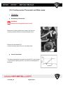
3.2.4 Cooling system Thermostat and Water pump
Thermostat:
Dismantling Thermostat:
WARNING:
Always use new gaskets and oil seals.
Disconnect cooling system hose, loosen and remove
mounting screws and remove the thermostat cover.
Remove the thermostat (5).
Verify that the by-pass hole (6) is not obstructed.
Check Thermostat
The thermostat begins and opens at around 75°C and reaches
7 mm minimum opening at 90°C, as shown in the diagram on
the figure.
ver.2009_03
Page 82/215
Check whether the thermostat pad is cracked.
Pass a cord through the flange as indicated in the figure.
Check the above-mentioned conditions by immerging the
thermostat (1) in a container with water, maintaining it in
suspension.
Slowly heat the water and check the temperature with a
thermometer (2).
When a temperature of 75°C is reached, the thermostat valve
begins to open and arrives at a temperature of 90°C.
The thermostat valve reaches an opening of at least 7 mm.
Change thermostat if necessary.
Check that the thermostat cover and the tubes connected to it are not broken, otherwise
change the damaged element.
Mounting the Thermostat
WARNING:
The thermostat must be mounted with the by-pass
hole (2) turned upwards, as shown on the figure.
Position thermostat (1) as indicated on the figure.
Position the thermostat cover and tighten with the two
mounting screws with specified torque:
10 N·m 1 Kg-m
ver.2009_03
Page 83/215
Dismantle Water Pump
Loosen and remove the two screws (4) and the small
plates (5).
Remove the entry elbow (6).
Loosen and remove the two screws (3) and remove the
water pump from the engine.
Remove O-Ring (7).
Loosen and remove two screws (8).
Remove the cover (9).
ver.2009_03
Page 84/215
Loosen and remove the nut (10) and remove the rotor (11).
Remove the external circlip (12), the internal circlip (13)
and the ball-bearing beneath.
Remove the liner (14), the shaft (15), the ball-bearing (16)
and oil seal beneath.
Remove the mechanical seal (17).
ver.2009_03
Page 85/215
Check the state of wear of the various components of the
pump.
Check that the various elements are not broken.
Change worn or damaged elements if necessary.
Water Pump Assembly
Position the pump body (1) on a support.
ATTENTION:
The oil seal must be inserted downwards with the
lip closed.
Position oil seal until it touches (2).
Grease the shaft (4) at the points indicated on the figure.
ver.2009_03
Page 86/215
Position the shaft (4) inside the pump body (1).
Position the first ball-bearing (5), using a press to make it
touch.
Position the liner (6).
Position the second ball-bearing (7), using a press to make it
touch.
Fix the ball-bearings with the external (8) and internal
(9)circlips.
ver.2009_03
Page 87/215
ATTENTION:
While mounting the counter-face and mechanical
seal make sure that they are clean and bear no traces
of grease.
Position the counter face as in the figure (10).
Position the mechanical seal (11) until it touches as shown in
the figure.
Position the rotor (12) making it meets clutch (A).
Position the sealing washer (13) and fix it tight with the nut
(14).
8 N·m 0.8 Kg-m
Always use LOCTITE 243®
ver.2009_03
Page 88/215
Position the cover and lock it tight with the two screws (15).
Position the sealing washer (16) and tightly screw the purge
screw (17) up.
10 N·m 1 Kg-m
Always use LOCTITE 243®
Position the O-Ring (18) on the pump body.
Position the entry elbow (19) and fix with the two small plates
(20) and the two screws (21) tightly.
10 N·m 1 Kg-m
ver.2009_03
Page 89/215
Position the pump (1) as in the figure and screw the two
screws
(2) up tightly.
10 N·m 1 Kg-m
Always use LOCTITE 243®
Reposition the entry and exit tubes (3) of the pump,
tightening two hose clamps (4).
ver.2009_03
Page 90/215
ver.2009_03
Page 91/215
4
Transmission
4.1 Transmission Dismantling
Remove engine out of the PWC (see Engine Removal
chapter).
Remove the engine oil by opening the oil plug screw on
the bottom of the engine
(19 mm socket required). Use suitable equipment to
collect the engine oil.
Remove the following parts:
-
Oil return line to the bottom of the engine
Oil supply line
Rear engine Support
Coupler cover
ver.2009_03
Page 92/215
Remove 2 x short and 10 x long 5mm mounting screws
Take note of short screw position (shown on figure)
Remove transmission cover with a suitable tool.
NOTE: do not damage the gasket surface of the
casting.
Remove the right hand thrust washer carefully and place
beside.
ver.2009_03
Page 93/215
Remove carefully the left hand transmission gear assy
and place beside.
Remove carefully the second thrust washer and place
beside.
Remove carefully the 3 x needle cage bearings and place
beside.
Remove carefully the left had thrust bearing and place it
beside.
ver.2009_03
Page 94/215
Remove Nut ( 41 mm) with an impact tool
Remove transmission gear with the gear wheel
remover.
Tighten the screws of gear wheel remover in X-method,
stopping the gear with a suitable tool.
Remove the gear and place it beside.
Remove 2 x transmission casing mounting screws and lower
banjo bolt.
NOTE: Remove the copper washer of lower banjo bolt.
ver.2009_03
Page 95/215
Remove transmission gear box casing and place it
beside.
Disassembling transmission cover
Support the transmission cover and use special tools to
open the coupler. Loosen and remove the coupler.
NOTE: The washer in between the bearing and the
gear has a thickness of 4,5mm
ver.2009_03
Page 96/215
Remove circlip and bearing
NOTE: The washer in between the oil seal and the bearing has a thickness of
1,5mm.
ver.2009_03
Page 97/215
Disassembling transmission housing:
Remove the oil seal and the O-ring.
4.2 Transmission Assembling
Assembling the transmission cover
Grease new oil seal on the seal lips and o the oil seal
groove. Press in the oil seal by hand.
ver.2009_03
Page 98/215
Press in the bearing and put in place the circlip to secure the bearing.
Subassembly of the PTO gear.
Press and glue the aluminum plug into the PTO gear with Loctite 648 as
shown on the pictures below. Put the washer ( 4,5 mm ) in place.
Install washer (1,5mm) in between the oil seal and the bearing using suitable tool.
ver.2009_03
Page 99/215
Assemble coupler into the PTO gear using grease and tighten the coupler with
specified torque.
Tightening torque: 80 N·m
Assembling transmission housing
Apply grease on the inside and sealing lips of the oil seal. Press in the oil seal.
NOTE: The greased side of the oil seal needs to be on the same side like the
painted side of the oil seal cover.
Put in place the O- ring. Apply Loctite 5699 on the O – Ring.
ver.2009_03
Page 100/215
Apply Loctite 5699 on the surface of the transmission
cover
Assembling transmission on the engine
Put in place the transmission housing and tighten 3 x
bolts.
NOTE: Pay attention not to damage the oil seal by
thread of the crankshaft
NOTE: Insure that the oil delivery line will be placed
in between the engine and the transmission housing.
Apply RED Weicon Lock AN 305-86 on the thread of all 3
screws. Ensure the copper gasket is used on the bigger
one.
ver.2009_03
Page 101/215
Tighten the 3 bolts with specified torque
Tightening torque: 45 N·m
Pressing in the transmission bolt
During pressing in the transmission bolt ensure the
lubrication holes are orientated to the right side ( 90 deg.
to the right).
Assembling the right hand side gear:
NOTE: For correct Crankshaft gear installation
apply Loctite 648 on the surface of the inner side of
the cone.
ver.2009_03
Page 102/215
Assembling the right hand side gear tightening nut:
NOTE: Apply RED Weicon Lock AN 305-86 on the thread of the tightening nut.
Block the gear and tighten the nut with a specified torque.
Tightening torque: 160 N·m
Put in place transmission parts on the right hand side of the transmission:
Put in place the thrust washer
Put in place the 1st cageless needle bearing
Put in place the 1st thrust ring.
Put in place the 2nd cageless needle bearing
Put in place the 2nd thrust ring.
Put in place the 3rd cageless needle bearing
Oil the bearing system:
ver.2009_03
Page 103/215
Put in place the right hand gear assembly.
Put in place the thrust washer of the right hand transmission gear.
Put in place the thrust washer of the left hand transmission gear.
Put in place the 3 x cage needle bearing
Oil the bearing system
Ensure the 2 x location pins are in place
Apply Loctite 5699 on the transmission housing sealing surface.
ver.2009_03
Page 104/215
Put the Paper gasket for the transmission cover in place.
Apply Loctite 5699 on the sealing surface of the transmission cover.
NOTE: The short screws are to be used on the left
hand side of the transmission like shown on the
figure.
Tighten using the other 10 screws
Tighten all 12 screws according to the tightening
procedure and with specified torque.
Tightening torque: 10 N·m
Install the oil lines in the order your removed them.
Apply RED Weicon Lock AN 305-86 and tighten the banjo bolt
with specified torque.
Tightening torque: 25 N·m
ver.2009_03
Page 105/215
Apply RED Weicon Lock AN 305-86 and tighten both banjo
bolts of oil suppling line with specified torque.
Tightening torque: 20 N·m
WARNING:
Pay attention for amount of used Locking agent on the oil line banjo bolts
thread. There is a risk of blocking oil passages.
Tighten the oil plug screw with specified torque.
Tightening torque: 30 N·m
Refill the proper oil volume in the engine.
ATTENTION:
Use only original HSR-Benelli engine oil
ver.2009_03
Page 106/215
4.3 Center flange bearing
Assembly of the flange bearing:
Grease the oil seal lips with water resistance grease on both sides.
RECOMMENDED LUBRICANT:
FUCHS URETHYN E/M 2
Use new pre-coated screws or apply blue Loctite 243
Put in place the flange bearing and tight
4 screws with specified torque.
Support the bearing with a hammer to put
the bearing on the top position.
Tightening torque: 30 N·m
ver.2009_03
Page 107/215
Put in place the flange bearing cover apply blue
Loctite 243 on the thread of the screws and tighten
the screws with specified torque.
Tightening torque: 10 N·m, in X-method
ver.2009_03
Page 108/215
ver.2009_03
Page 109/215
5 PUMP AND IMPELLER
5.1 Jet Pump overview
(Series-R Pro pump shown)
ver.2009_03
Page 110/215
NOTE:
Series-S and Series-R engines have closed-loop cooling system. The radiator is
integrated into jet pump housing which is connected to the cooling system lines.
WARNING:
Each time JET PUMP STATOR or JET PUMP
assembly were removed from the hull, engine
coolant could flow out.
After reassembling jet pump to the vehicle always
perform engine coolant level check and refill to
specified volume if necessary.
5.2 JET PUMP DISASSEMBLING
Remove the O- rings from the jet pump and place it beside.
Remove 4 x Allen screws ( m5 ) locking the Nozzle.
Remove Jet Pump housing, Impeller housing with the Stator.
Remove 3 x screws of the stator cone.
ver.2009_03
Page 111/215
Remove cone.
NOTE: Pay attention on the white O-ring in order not to lose it.
Cleaning of the water sieve in the Jet Pump:
NOTE: The water sieve protects the exhaust cooling system from sand and other
particles to block the water supply.
A heat sensor will warn you and slow down your personal PWC into the “limp home
mode” of 4000 rpm. This requires regular maintenance.
(There is a second one in the water injection of the exhaust system).
Remove the sieve out of the housing with a tool.
ver.2009_03
Page 112/215
Removing of the Impeller:
Remove the impeller from the impeller shaft by loosen the impeller with a
Special Tool.
Block the impeller shaft. (See Photo beside).
NOTE: Remove the Impeller shaft with a soft tool in order to avoid damages on the
thread.
Remove the impeller shaft.
Disassembly of the Stator Housing of the Jet Pump:
Remove the bearings out of the housing with a soft tool.
ver.2009_03
Page 113/215
NOTE: Take care of bearings place for correct
assembling.
Disassembly of the Jet Pump Housing
Disassembly of the Jet Pump Housing carrying the Liner for
the engine Radiator.
NOTE: The Jet Pump housing and the Liner cannot be
taken apart and need to be replaced as one for repair.
Remove the cooling water supply hose.
Disassembly of the Jet Pump nozzles:
Open with an allen screw driver (M 6mm) the screws
on the left and right hand side of the steering nozzle.
ver.2009_03
Page 114/215
Remove the spring located on the Nozzles.
Remove the Steering nozzle.
Remove plastic bushings from the steering nozzle
with a soft tool carefully.
Remove the allen screw (M 6 mm) from the trim nozzle.
ver.2009_03
Page 115/215
Remove the Trim Nozzle.
Remove the plastic bushing with a soft tool carefully.
NOTE: For Reverse Equipped PWC only:
Remove the reverse support from the jet pump with an
allen screw Driver (M 6mm)
5.3 ASSEMBLING THE JET PUMP
NOTE: For Reverse Equipped PWC only
Apply blue Loctite 243 on the threads of the screws
ver.2009_03
Page 116/215
Tighten the reverse support on the Jet Pump Housing.
Tightening torque: 20 N·m
Reinstall the jet pump nozzles
Press in the new plastic bushings into the trim nozzle
Apply blue Loctite 243 on the threads of the screw tightening the
Trim nozzle.
Tighten the screw with specified torque.
Tightening torque: 20 N·m
ver.2009_03
Page 117/215
Press in the new plastic bushings into the steering nozzle
Apply blue Loctite 243 on the beginning of the threads of the
screw and tighten the screws with specified torque.
Tightening torque: 20 N·m
Proceed the same process on both sides of the pump.
Assembly of the Stator Housing of the Jet Pump
Assembly of the Jet Pump Housing:
.
Put in place the first (smaller in diameter) bearing.
ver.2009_03
Page 118/215
Press in the first bearing (smaller in diameter) bearing with a tool.
Put in place the second (smaller in diameter) bearing with a tool.
Press in the second bearing (smaller in diameter) bearing with a tool.
ver.2009_03
Page 119/215
Put in place the distance sleeve.
Put in place the third bearing (bigger diameter).
Press in the third bearing (bigger diameter) with a special tool.
Take a new oil seal and apply grease in the lips.
Place the oil seal on the sleeve.
RECOMMENDED LUBRICANT:
FUCHS URETHYN E/M 2
ver.2009_03
Page 120/215
Press in the new oil seal with a tool very carefully
Apply grease on the remaining sleeve and put it in place.
RECOMMENDED LUBRICANT:
FUCHS URETHYN E/M 2
Put in place the sieve in the housing.
Put in place the sieve housing and apply blue Loctite on the
beginning of the thread
ver.2009_03
Page 121/215
Tighten the screws for the sieve housing with specified torque.
Tightening torque: 10 N·m, in X-method
Apply grease on the impeller shaft all the way around.
RECOMMENDED LUBRICANT:
FUCHS URETHYN E/M 2
Press in the Impeller Shaft.
Assembly of the Impeller:
Screw carefully the Impeller on the Impeller Shaft and tighten it
by hand.
ver.2009_03
Page 122/215
Use a special tool to tighten the impeller to the final torque.
Tighten the Impeller to the specified torque.
Tightening torque: 100 N·m
Put in place the white plastic ring.
ver.2009_03
Page 123/215
Apply blue Loctite 243 on the screws of the cone and tighten it with a specified torque.
Tightening torque: 7 N·m
Apply blue Loctite 243 in the thread of the water supply tube
And tighten the tube on the housing.
Put in place the O-Ring and apply slightly grease on the surface.
Apply grease on the sockets of the Impeller housing.
ver.2009_03
Page 124/215
Put in place the Stator Housing on the Impeller Housing
Put in place the Nozzle assembly
Apply blue Loctite 243 on the beginning of the threads of the screws.
Tighten the screws with specified torque.
Tightening torque: 25 N·m, in X-method
ver.2009_03
Page 125/215
Put in place the O – Rings and the rubber cone and the rubber seal.
Final assembly of the Jet Pump.
ver.2009_03
Page 126/215
5.4 Jet Pump Assembly into the PWC
Grease the sealing lips of the jet pump.
Assemble the Flange bearing with it`s 4 screws into the rear of jet pump tunnel. Apply blue
Loctite 243 on the threads of the screws or take new micro coated screws.
Support the Flange bearing during assembly with a hammer to pull it on the top position
during tightening.
Tighten the screws with specified torque.
Tightening torque: 30 N·m, in X-method
ver.2009_03
Page 127/215
In order to put the O - Rings on the jet pump housing grease the grooves for easy assembly.
Apply blue Loctite 243 on the thread of the screws. Tighten the screws with specified torque.
Tightening torque: 30 N·m, in X-method
Put in place the impeller housing with the impeller on the jet pump housing.
Apply blue Loctite 243 on the threads of the screws and tighten with Tighten the screws with
specified torque.
Tightening torque: 20 Nm.
ver.2009_03
Page 128/215
5.5 Assembly of the Reverse Gear
(For Series – R Pro Model only)
Put in place the sleeves of the reverse shield.
Apply blue Loctite 243 on the thread of the screws and put 2x per side the washer in place.
Tightening torque: 10 Nm.
NOTE: Ensure the reverse shield moves easily.
ver.2009_03
Page 129/215
5.6 Assembling riding plate
Apply blue Loctite 243 on the thread of the screws.
Put in place the Riding Plate and tighten 4 x screws with specified torque.
Tightening torque: 12 Nm.
5.7 Steering cable setting
Hold the steering in straight forward position.
The distance of the jet nozzle to the jet drive outlet
must be the same on the left and the
right side. Otherwise, adjust the steering cable
accordingly.
To disconnect the steering cable from the jet nozzle at the ball joint, you must first pull
the steering cable back. Then, pull up on the connection. The cable will be free from
the connection.
The distance should be the same on both sides. (x)
WARNING:
Pay special attention when assembling components of steering system. Non
proper assembling could result lost of contol during riding vehicle.
ver.2009_03
Page 130/215
5.8 Trim system bleeding
NOTE: Put protection on the hull to avoid brake liquid contact with the paint of the
hull!
Fill an injector like shown in the picture with brake liquid half the way (10 cm3) and screw a
bleeding nipple into the trim system. Put covering material on the PWC in order to protect the
paint of the deck.
Attach the Injector with a hose and tighten it with a plastic clamp.
Press the injector 10 times.
Put the nozzle in top position and repeat the injector pump process 10 times.
Put the nozzle in bottom position and repeat the injector pump process 10 times.
ver.2009_03
Page 131/215
Keep the Injector pressurized and pump the nozzle up and down until no air bubbles are
released to Injector.
Put paper underneath the trim lever to collect remaining brake liquid.
Remove the Injector, bleeding nipple, put in place O – Ring and screw the plug loosely into
the Trim lever body.
Tilt the nozzle to the top position and ensure the excessive brake fluid will be released of the
trim lever.
Tighten the plug screw.
Clean the trim leaver with a cleaner in order to avoid brake
liquid contact with the paint of the hull.
ver.2009_03
Page 132/215
ver.2009_03
Page 133/215
6 Fuel system
6.1 Fuel Tank and Fuel Pump
Fuel tank disassembly out of the PWC:
(Shown for Series-R Pro)
Remove the 2 x screws of the fuel tank belts on the bottom of
the hull.
Unscrew the clamp of the fuel filling hose and remove the
hose.
NOTE: Pump out any remaining fuel out of the tank if
required.
Remove the fuel tank out of the hull.
Disassembly of the fuel pump out of the fuel tank:
Unscrew the 6 x screw from the fuel pump.
ver.2009_03
Page 134/215
Pull out the fuel pump carefully out of the fuel tank.
Fuel pump filter and fuel pressure regulator are located
on the fuel pump.
Assembly of the fuel pump into the fuel tank:
Put back in place the fuel pump for assembly.
NOTE: It is EXTREMELY important to insure that
THE FUEL FILTER IS NOT SQUECED INBETWEEN THE
FUEL PUM AND THE TANK.
There is the risk of leaking fuel into the hull.
Apply blue Loctite 243 on the thread of the screws of the fuel
tank.
ver.2009_03
Page 135/215
Screw in the screws and tighten them with specified torque.
Tightening torque: 5 N·m, in X-method
Leak test of the subassembly of the Fuel Pump/Fuel Tank
Note: Always perform a leak test during fuel tank disassembly/
fuel pump inspection.
Apply a pressure of 0,3 bar into the tank system and check
for loss of pressure with the help a spray test. (see picture)
Release the pressure carefully by opening the fuel cap as
shown in the picture.
ver.2009_03
Page 136/215
Assembly of the Fuel tank into the PWC:
Put back the fuel tank into the PWC as shownin the picture.
Reinstall the fuel tank hose with the clam on the fuel tank.
Apply blue Loctite 243 on the thread of the screw and tighten
with specified torque.
Tightening torque: 10 N·m
ver.2009_03
Page 137/215
ver.2009_03
Page 138/215
7 Exhaust system
7.1 Muffler and Hoses:
(Shown for Series-R Pro)
Overview of the exhaust system in the Hull
Inject 15 ml of engine oil into the exhaust muffler ensuring
the temperature sensor will recognize the exhaust temperature
in the exhaust system.
Put in place the copper gasket and the temperature sensor
Apply green Loctite 278 and tighten the sensor with specified torque.
Tightening torque: 20 N·m
ver.2009_03
Page 139/215
Apply Loctite on the thread of the screw tightening the exhaust mounting belt.
Put the exhaust hose on the fitting in the Jet pump tunnel.
Put in place the remaining hoses and tubes for the exhaust system shown on the pictures.
Tighten the exhaust end flange with 6 x screws and apply Blue Loctite 243 on the threads
and tighten in with 5 Nm
ver.2009_03
Page 140/215
7.2 Exhaust Manifold:
In order to assemble the Exhaust Maifold following parts have
to be assembled.
NOTE: There are two different injectors with different
Inner diameters.
Apply green Loctite 278 on the thread of the water injectors used on exhaust tubes of
exhaust manifold.
Tighten the water injectors on its predefined position on the exhaust manifold to be in line.
Apply Green Loctite 278 on the thread of the fitting, tighten it and turn it into the final position.
ver.2009_03
Page 141/215
There are three different fittings for the 3 in 1 exhaust hose.
Take the fitting with smaller inner diameter, apply green Loctite 278 on the thread and tighten
the fitting as shown on the picture.
.
Take the fitting with the bigger inner diameter apply green Loctite 278 and tighten it.
Take the L - fitting and apply green Loctite 278 and tighten it to the position like shown on the
photo.
The view of the final
assembly:
ver.2009_03
Page 142/215
Apply gasket seal Loctite 5699 on both sides of the exhaust gasket.
Put the applied gasket on the exhaust manifold as shown on the picture.
NOTE: the cut edge of the gasket needs to be inline with the shape of the exhaust
manifold.
Apply blue Loctite 243 on the thread of the screws and tighten them with specified torque.
Tightening torque: 30 N·m
ver.2009_03
Page 143/215
Final assembly of the exhaust manifold and the 3 to 1 exhaust hose view:
7.3 Assembling the hoses on exhaust manifold
There are two hoses of 135 mm length that need to be installed between the fittings of the
exhaust manifold. Clamps are tightening the hoses.
Install 2 x 80mm hoses like shown on the pictures. Clamp in the same way as shown above.
ver.2009_03
Page 144/215
Assemble and clamp the big hose like shown on the picture.
7.4 Leak test of the Exhaust hose:
The equipment of the leak test is shown bellow.
1. Manometer
2. Long hose
3. Short hose
Link the test equipment in between the outlet of the manifold and the outlet of the 3 in 1
exhaust hose fitting.
The circle of the water jacket should be closed by the mentioned equipment for the test.
Apply air pressure of 3 bar into the system.
ver.2009_03
Page 145/215
Put the exhaust system into a water bath and check for
air bubbles.
7.5 Assembling the exhaust manifold on the engine
Apply blue Loctite 243 on the stainless steel nut and hand
tight them on the stud screws of the cylinder head.
Tighten the screws in the X - Method with a specified torque
starting with the 2nd cylinder continuing on 1st or 3rd cylinder
and finalizing respectively on the 3rd or 1st cylinder.
Tightening torque: 10 N·m
ver.2009_03
Page 146/215
ver.2009_03
Page 147/215
8 Cooling system
8.1 Closed circuit cooling system
Series-S
Pos.
1
2
3
4
5
6
7
8
9
10
ver.2009_03
Part description
ASM COOLING PIPES ENGINE
SCREW
COOLING HOSE HOT 1
COOLING HOSE HOT 2
COOLING HOSE COLD
HOSE CLAMP 38,1
HOSE CLAMP 25-40
SCREW CAP 1,4 BAR
THREADED T-PIECE
PADS
Page 148/215
Q-ty
1
1
1
1
1
2
4
1
1
2
Series-R
Pos.
1
2
3
4
5
6
7
8
9
10
11
ver.2009_03
Part description
ASM COOLING ENGINE
SCREW M5X10
COOLING HOSE COLD 3Z
COOLING HOSE HOT SHORT 3Z
COOLING HOSE HOT LONG 3Z
HOSE CLAMP 38,1
HOSE CLAMP 25-40
THREADED T-PIECE
PADS
BRACKET COOLING HOSE
SCREW CAP
Page 149/215
Q-ty
1
1
1
1
1
2
4
1
3
1
1
8.2 Opened circuit systems:
Series-S
ver.2009_03
Page 150/215
Series-S cooling system components:
Pos. Part description
Q-ty
A
OIL COOLER
1
B
WATER MANIFOLD
1
C
T-TYPE FITTING, M8 THREAD
1
D
PLUG BLOT M8X10
1
E
EXHAUST MANIFOLD
F
MAGNETIC VALVE IP67
1
G
T-TYPE FITTING
3
J
INLINE FILTER
1
K
INJECTOR EXHAUST
1
L
REDUCTION FITTINGSLEEVE 4,5 MM
3
M
BYPASS FITTING DN9 BLACK
3
1
INTAKE LINE OIL COOLING HOSE, INNER D 13MM
120CM
2
FLUSHING SYSTEM HOSE, INNER D 10MM
30 CM
3
INTAKE LINE OIL COOLING HOSE, INNER D 10MM
10/10/10 CM
3
EXIT LINE OIL COOLING HOSE, INNER D 10MM
50/45/40 CM
4
EXIT LINE OIL COOLING HOSE, INNER D 10MM
33CM
5
EXIT LINE OIL COOLING HOSE, INNER D 10MM
35CM
6
EXIT LINE EXHAUST COOLING HOSE, INNER D 13MM
36CM
7
INTAKE LINE EXHAUST COOLING HOSE, INNER D 10MM
80CM
8
EXHAUST MANIFOLD COOLING HOSE, INNER D 10MM
10CM
9
EXHAUST MANIFOLD COOLING HOSE, INNER D 10MM
11,5CM
10
EXHAUST MANIFOLD COOLING HOSE, INNER D 10MM
8,5CM
11
INLINE FILTER HOSE, INNER D 10 MM
25,5CM
12
INLINE FILTER HOSE, INNER D 10 MM
36CM
13
MAGNETIC VALVE HOSE, INNER D 6 MM
40CM
ver.2009_03
Page 151/215
Series-R
Series-R cooling system components:
Pos. Part description
Q-ty
A
OIL COOLER
1
B
WATER MANIFOLD
2
C
3IN1 EXHAUST HOSE
1
D
EXHAUST MANIFOLD
1
E
MAGNETIC VALVE IP67
1
F
T-TYPE FITTING 5MM
2
G
L-TYPE FITTING 5MM
1
H
T-TYPE FITTING 3MM
3
I
INLINE FILTER
1
J
SPREDSERT M6 X 12,7
1
K
ELBOW SCREW-IN NOZZLE
1
L
SCREW-IN HOSE NOZZLE
1
M
BYPASS FITTING DN9 BLACK
1
N
REDUCTION FITTINGSLEEVE 4,5 MM
1
ver.2009_03
Page 152/215
1
INTAKE LINE OIL COOLING HOSE, INNER D 13MM
85CM
2
INTAKE LINE OIL COOLING HOSE, INNER D 10MM
50/45/40 CM
3
EXIT LINE OIL COOLING HOSE, INNER D 10MM
50/45/40 CM
4
EXIT LINE OIL COOLING HOSE, INNER D 13MM
105CM
5
INTAKE LINE EXHAUST COOLING HOSE, INNER D 10MM
115CM
6
FLUSHING SYSTEM HOSE, INNER D 10MM
50 CM
7
INTAKE LINE EXHAUST COOLING HOSE, INNER D 10MM
25CM
8
MAGNETIC VALVE HOSE, INNER D 6 MM
27CM
9
INLINE FILTER HOSE, INNER D 10 MM
15CM
10
EXIT LINE EXHAUST COOLING HOSE, INNER D 10MM
150CM
11
EXHAUST MANIFOLD COOLING HOSE, INNER D 10MM
85CM
12
INLINE FILTER HOSE, INNER D 10 MM
10CM
13
EXHAUST MANIFOLD COOLING HOSE, INNER D 10MM
8CM
14
EXHAUST MANIFOLD COOLING HOSE, INNER D 10MM
13,5CM
8.2.1 Exhaust cooling system
Overview of the exhaust cooling system (Shown for Series-R):
ver.2009_03
Page 153/215
The flow of the cooling liquid:
The water enters the system through wards the Jet Pump tunnel.
The T – Fitting splits the water flow into the exhaust manifold
and the
Flushing system hose.
The hose for the exhaust manifold cooling system feeds first
the end of the manifolds
ver.2009_03
Page 154/215
and goes through wards the tubes up to the end where the
headed liquid is collected. It leaves the system on the left
hand side of the manifold and
returns to the 3 to 1 hose on order to cool it.
It leaves the 3 in 1 hose through wards a fitting to exit the
system via a hose to left rear part of the PWC.
ver.2009_03
Page 155/215
8.2.2 Oil cooling system
The coolant for the oil cooler is supplied with hose from the Jet
Pump at the rear of the PWC.
The coolant is split into the oil cooler through wards the
coolant water manifold.
It passes the oil cooler and enters a second water manifold
And goes through the hull to be released through wards a
fitting in the jet pump tunnel.
ver.2009_03
Page 156/215
ver.2009_03
Page 157/215
9 Steering system
SERIES-R STEERING SYSTEM
9.1 Steering Support Assembly
(For Series-R model only)
Take the steering support and press in the bearing inside the steering support by hand.
Put the steering tube in place
Put in place the second bearing and press it in by hand.
Use a tool to install bearing circlip in place.
ver.2009_03
Page 158/215
Grease the oil seal and press it in by hand.
Oil seal needs to be in line with Steering support.
Put in place steering axle and put it in carefully with a soft hammer.
NOTE: Ensure the parts are in line and are sliding carefully.
Put in place the ring.
Put in place the steering lever.
Put in place the indicator disc.
Apply BLUE Weicon Lock AN 302-43 on the thread and tighten nut with specified torque.
Tightening torque: 25 N·m
ver.2009_03
Page 159/215
Assemble and tighten SSSA sensor support with 2 x screws
(Apply BLUE Weicon Lock AN 302-43 on screws thread)
NOTE: SSSA sensor needs to be flattened to the support
before tightening screws.
After final assembly please perform a check. Steering shaft
should move easily.
9.2 Assembly of the Steering Support on the PWC
(For Series-R model only)
Put in place steering support by tilting it.
Apply blue Loctite on thread of 6 mount screws.
ver.2009_03
Page 160/215
Tighten the screws with specified torque.
Tightening torque: 20 N·m, in X-method
9.3 Handle Bar assembly
(For Series-R model only)
Assembly of the handelbar:
Assembling grips on the handle bar.
Apply Loctite 435 to insure the grips will not become loose.
Press by hand the grips on the handle bar after the Loctite has
been applied.
ver.2009_03
Page 161/215
Final assembly of the handle bar.
Assembly of the handlebar on the PWC:
Ensure you put in place Start-Stop switch wire first.
Put in place the handle bar cover.
Apply BLUE Weicon Lock AN 302-43 on the threads of
handlebar cover screws.
Tighten screws with specified torque.
ver.2009_03
Page 162/215
Tightening torque: 25 N·m, in X-method
Put throttle cable end in the throttle lever hole.
Assemble Trim oil line with the banjo-bolt.
Tighten trim lever on the handlebar.
ver.2009_03
Page 163/215
Tighten the Start-Stop switch on the handle bar.
SERIES-S STEERING SYSTEM
9.4
Handle Pole Assembly:
Parts for the Handle Pole assembly:
ver.2009_03
Page 164/215
Assemble the red protection bar and tighten the screws for the extension
Stick two aluminum profiles into the Handle Pole plate as shown in the picture
Apply Loctite 243 on the thread of the 8 screws ( M5 x 35) as shown on the photo.
Tighten the screws into the handle bar and tighten them with specified torque.
Tightening torque: 5 N·m, X-method
Apply Loctite 3425 A&B on the top end of the handle bar and stick it together like shown on
the photo.
ver.2009_03
Page 165/215
Apply Loctite 243 on the thread of the screws and tighten them with specified torque.
Tightening torque: 5 N·m
Put the bushings in place and press them in with your fingers.
Put the rubber protector of the lower handle plate in place and ensure the flatten side will be
in position as shown on the photos. Tighten the screws.
ver.2009_03
Page 166/215
Put the rubber protector of the lower handling plate in place. Ensure the flatten side will show
to the upper side as shown on the photos. Tighten the screws.
Assemble the springs of the handle bar. Warm the hose if needed and pull it on the spring.
Cut the remaining hose 3- 5 mm from the end of the spring with a knife.
Grease the Handle bar shaft and put it in place as shown on the photos.
Put in place the spring for the Handle bar and push carefully the bolt
through the pushing.
ver.2009_03
Page 167/215
Press down the spring and screw in the bold with a tool.
NOTE: Do not use hammer to install the bolt. This will lead to destroy the thread on
the handle bar support.
Tighten the bolt with a torque meter.
Tightening torque: 25 N·m
Assembly of the dashboard in the handle bar:
Put in place the bracket for the dashboard. And assemble it according to the pictures.
Assemble the dashboard like shown on the photos bellow.
Put 2 washers on the screws to insure the proper distance.
ver.2009_03
Page 168/215
Put in place the dashboard into the handle bar. Tighten the dash board on the handle bar
with 3 NM.
Assembly of the locking pin for the handle bar:
Put in place the location pin into the handle bar support.
Put in place the locking pin ball by hand
Put in place the location pin holder and tighten it
Clean the aluminum part of the handle bar and put the safety stickers on it. Put in place the
sticker for the load of the vehicle.
ver.2009_03
Page 169/215
9.5 Handle Bar Assembly
Apply Loctite 243 on the Screw for the steering control bushing. Put the bearing in place and
press it on the steering control bushing.
Put the steering control lever in place.
Put the subassembly of the steering control bushing in place. Put in place the second ball
bearing and press it in.
ver.2009_03
Page 170/215
Apply Loctite 243 on the thread of the second steering control bushing and put it in place.
Tighten the system with a torque meter.
Tightening torque: 20 N·m
Take the ball joint screw and apply Loctite 243 on the thread of the screw. Tighten the ball
joint.
Put the Handle bar, clamp and mounting screws in place.
Tighten the screws with a torque meter.
Tightening torque: 20 N·m
9.6 Assembly of the Handle Bar on the PWC
Place on the RIGHT SIDE of PWC: Trim, Dashboard and the
Start Stop switch wire
Place on the LEFT SIDE of PWC: Throttle and Steering cables
Take left two cables for Throttle and Steering and put them
through the handle bar
ver.2009_03
Page 171/215
Take the other 3 cables for Trim system, Dashboard and from Start-Stop switch (two wires)
and put it through the handle bar .
Apply Loctite 243 on the 4 screws for the fixation of the handle bar.
Tighten screws with specified torque in x Method
Tightening torque: 30 N·m
Connect the dashboard wire and place it into the handle bar.
Put in place the Start-Stop Switch and connect the wires.
Put in place throttle cable on the throttle lever and put assemblies (throttle lever and StartStop switch) on the steering system.
ver.2009_03
Page 172/215
Put in place wiring protection clamp. Tighten the screws on the handle bar.
Fix cable with a tie rap.
NOTE: for initial adjustment of the steering cable install the fastener on steering cable
thread (steering plate side) with 12 full turns. Do the same for cable end on Jet pump
side. This should lead to a proper balanced adjustment of the steering system.
Connect steering cable with the Steering lever and Jet pump steering nozzle.
Do a control measurement as follows:
Take a ruler and aline it on the nozzle of the jet pump.
Take a measurement tool and measure the adjustment for the jet pump on both sides.
Adjust it accordingly.
ver.2009_03
Page 173/215
Assembly of the Trim lever:
Put the O – Ring in place
Put banjo-bolt into the fitting of trim system line, put second O-ring in place and Tighten the
bolt.
Bleed the system: See Trim system bleeding in PUMP chapter.
Assemble the hand grips
Put Loctite 435 in the hand grips and distribute it internally. Pull hand grips on the handle bar.
Tighten Throttle lever assembly, Trim lever and Start-Stop switch body.
ver.2009_03
Page 174/215
Put in place rubber grommet for the wires/cables of the handle pole
NOTE: Please check that cables are moving freely
WARNING:
If throttle cable is not moving freely PWC could suddenly accelerate on its own
while steering.
Put in place handle bar protector with two tie raps and cut the extending tie rap ends.
ver.2009_03
Page 175/215
Install the Throttle cable and insure there is free play of 2-3 mm on the throttle lever.
Do a final test on Start-Stop switch buttons to check electrical system operation.
ver.2009_03
Page 176/215
ver.2009_03
Page 177/215
10 Hull
10.1 Dashboard cover
(For Series-R model only)
Disassembly of dashboard cover
Remove the support plate screw from the dashboard and carefully remove the dashboard
equipment by hand.
NOTE: Take care not to damage the gasket.
Reassembly of the dashboard cover
NOTE: Take care not to damage dashboard gasket.
ver.2009_03
Page 178/215
Apply BLUE Weicon Lock AN 302-43 on the screws like shown on the photo.
NOTE: It is very important to tighten the dashboard screws with the proper
torque of 2 Nm.
The other two screws need to be tightened with 5 Nm.
Assembly on the PWC
Put in place the dashboard cover on the PWC
Apply BLUE Weicon Lock AN 302-43 on thread of the screws (2 types of screws: Top M6 x
12 below M6 x 20)
Tighten the 6 screws with specified torque.
Tightening torque: 3 N·m, in X-method
ver.2009_03
Page 179/215
10.2 Drainage box
Those are the products you need to assemble a drainage box.
Note: The Method of gluing requires 2 components:
The Primer and the glue
Apply Primer on the surface that need to be glued.
Apply liquid Loctite on the surface that need to be glued.
Ensure you are putting primer and glue on the latches
connecting both halfs of the drainage box.
Apply BLUE Weicon Lock AN 302-43 on the thread of the
screw to put in place the drainage box in the hull.
ver.2009_03
Page 180/215
Tighten the screw for the drainage box.
Put in place the Hose sucking the water out of the hull into the
Jet Pump tunnel to be released.
.
10.3 Baggage Cover:
Assemly of baggage cover (electric Reverse button for Sereis-R Pro only)
Those are the parts involved in the assembly of the Baggage
Cover.
Assemble the axles with the springs and put it into the baggage cover on both sides.
ver.2009_03
Page 181/215
Put in place the circlips with a
suitable tool in order to lock the
springs. Insure the system is
working easily and properly.
Note: For Series – R Pro only (Reverse Switch).Put in place the reverse switch and wire.
Apply BLUE Weicon Lock AN 302-43 on the thread as shown on the picture.
Put in place the connectors for the electric reverse cable.
Assembly of the hood latch:
Install the axel into the latch through wards the spring. Tighten the latch with 2 x screws.
ver.2009_03
Page 182/215
Final view of baggage hood
Assembly of the luggage on the PWC deck.
Put in place the baggage cover on the PWC by hooking in the
levers with the spring under plastic covers.
NOTE: for Models with electric reverse only.
Put the electric cable through the hole of the dashboard.
Apply BLUE Weicon Lock AN 302-43 on the thread of the
screws of the baggage latch cover.
ver.2009_03
Page 183/215
Tighten the screws with a specified torque in x – method.
Tightening torque: 5 Nm, in X-method
10.4 Side Cover Assembling
Apply BLUE Weicon Lock AN 302-43 on the thread of the base
stud.
Screw in the base stud by hand and let the Loctite dry out.
Put in place the side cover.
Put in place the rubber washers and tighten self-locking nut
carefully by hand.
ver.2009_03
Page 184/215
10.5 Sponsons assembling
Apply BLUE Weicon Lock AN 302-43 on the thread of the screws
Put in place the sponsons ground plate.
Tighten it with specified torque.
Tightening torque: 15 N·m
Put in place the sponsons and tighten it with5 Nm
ver.2009_03
Page 185/215
ver.2009_03
Page 186/215
11 Electrical System
11.1 General view (SERIES-S wiring diagram)
ver.2009_03
Page 187/215
11.1.1 Sector A
11.1.2 Sector B
ver.2009_03
Page 188/215
11.1.3 Sector C
11.1.4 Sector D
ver.2009_03
Page 189/215
11.1.5 Sector E
11.1.6 Sector F
ver.2009_03
Page 190/215
11.1.7 Sector G
11.1.8 Sector H
ver.2009_03
Page 191/215
11.2 General view (SERIES-R wiring diagram)
ver.2009_03
Page 192/215
11.2.1 Sector A
11.2.2 Sector B
ver.2009_03
Page 193/215
11.2.3 Sector C
11.2.4 Sector D
ver.2009_03
Page 194/215
11.2.5 Sector E
11.2.6 Sector F
ver.2009_03
Page 195/215
11.2.5 Sector G
11.2.5 Sector H
ver.2009_03
Page 196/215
ver.2009_03
Page 197/215
12 HSR-Benelli diagnostic system
12.1 HSR-Benelli Utility Diagnostic System (HUDS)
installation (Benelli engine version)
1. Save provided file “HUDS_Series R and S.rar” to the hard disk of your
computer.
2. Open this file from location where you’ve saved it (WinRAR or analog
software is required):
3. Select folder “HUDS_Series R and S” and press button “Extract To” on the
upper bar.
ver.2009_03
Page 198/215
4. Click OK to Extract folder to the directory were your RAR-file was saved. (To
change destination folder use right explorer panel to choose it, then press
OK).
5. Close WinRAR window. Go to the location folder of RAR-file.
Folder “HUDS_Series R and S” should appear:
ver.2009_03
Page 199/215
6. Open folder “HUDS_Series R and S” and start the file “ServiceHSR564.exe”:
7. The following window should appear:
ver.2009_03
Page 200/215
8. Click “OK" and choose language file (English or Italian are currently
available), press “Open” button:
ver.2009_03
Page 201/215
9. Next window “Select device” will open.
Choose file “CNS_B1HSR_07$US_NEW.dcn” and click “Open”:
ver.2009_03
Page 202/215
10. Program start view:
NOTE: If your computer isn‟t equipped with a COM port, see “using USB-toCOM adapter” chapter below:
Using USB-to-COM adapter
If direct COM (RS-232) connection is not possible for your computer USB-to-COM
adapter should be used to complete Diagnostic or Registration process.
USB-to-COM adapters are after-market
available . The general view of adapter is
shown on the picture.
ver.2009_03
Page 203/215
Adapter settings.
NOTE: For a perfect operation the adapter should be configured in a range
COM1-COM4 of your system.
Please contact your IT administrator if required to complete this setting.
12.2 HSR Diagnostic Tool settings
Start Diagnostic software as described above. Press “COM” button of the upper
panel.
The window will appear:
Select the COM port equal to your Adapter system settings (see above) and click
“Close” button.
Now the HSR Diagnostic Tool should work correctly. If there are any problems
please contact your IT Administrator.
ver.2009_03
Page 204/215
12.3 Vehicle registration process
NOTE: ECU of each new vehicle is limited to maximum 2500 rpm before
registration process is completed. Warranty period starts from date of
registration.
WARNING:
ECU could be registered only ONCE. Do not attempt to register ECU for
troubleshooting purposes.
Install HUDS software as described above.
NOTE: Check that Diagnostic cable is attached to a proper connector of vehicle
with its one end and to the COM-port of your computer with other end. (see
using USB-to-COM adapter if necessary).
Attachment of Diagnostic cable to
Series-R connector.
(Placed at rear left side of vehicle engine
compartment, close to battery.
Corresponding connector of wire harness is
to be disconnected during diagnostic
process.)
Ensure that safety lanyard is inserted to the
STOP button of vehicle (ignition is on)
ver.2009_03
Page 205/215
Starting Registration process.
Start program by “ServiceHSR564.exe” file.
Click “End Of Line” button on the upper panel. The “Line End Parameters” window
should appear:
5
1
2
4
3
This window should be used to complete vehicle warranty registration (put VIN
(Chassis number), *1, Engine number, *2)
To get the activation code for releasing ECU to full power mode please copy ECU
code from field “ECU_CODE” (*3) and insert this number during vehicle warranty
registration procedure using on-line B2B system. (see B2B 2nd generation features
below).
ver.2009_03
Page 206/215
Registration in B2B system.
Use the following link to access B2B system:
http://hsrtest.xpml.at/
Fill in your Login and Password and
click “Login” buton.
Fill in corresponding fields
with unit’s data:
VIN number
(=CHASSIS
NUMBER, to be
copied from field *1
of Line End
paraneters, see
above)
Engine number (to
be copied from
field *2)
ECU number
(=ECU CODE, to
be copied from
field *3)
Select Usage Type
Enter Customer
Information fields
Attach invoice
(scanned copy)
proving unit’s sale.
Click “Register” button to complete Registration.
ver.2009_03
Page 207/215
Activation Code will appear in next
window:
Copy the activation key and go back to
Diagnostic system.
Finalizing Registration process.
Once received from B2B the Activation
code should be copied and pasted to the field “UNLOCK_CODE” (*4) of End Line
Parameters window.
To complete the ECU Unlocking procedure press “Set Line End Parameters” button
(*5).
ECU is unlocked now, vehicle could be operated in full power mode.
12.4 Periodic maintenance registration process
Periodic Maintenance registration
NOTE: In order to maintain Warranty during the warranty period it is absolutely
necessary to record the maintenance based on periodic maintenance schedule
in time in the B2B unit history.
The maintenance schedule is available in B2B download area.
ver.2009_03
Page 208/215
To start Maintenance registration click “Unit History” button on the upper panel:
Click
here
Next window view:
Click for unit
search
Click to open registered units
list
ver.2009_03
Page 209/215
Registered Unit window example:
Click to select
unit
Scroll Unit History page to reach Maintenance field. Example of Maintenance field:
Click to register new
maintenance
ver.2009_03
Page 210/215
Maintenance Entry window will open. To register performed maintenance fill the
following fields:
•
Maintenance Interval – Select performed maintenanace (10 hours, 25 hours,
50 hours, 75 hours, etc.)
•
Hours – Enter vehicle current Motor Hours value
•
Comment – Add your comments if necessary
•
ECU-File – Ensure the filled in HUDS file (screenshot) is attached
•
ECU- File – Ensure the invoice for performed service (scanned copy) is
attached
Click “Add maintenance entry” button to save Maintenance Entry in Unit’s history.
Maintenance Registration is complete.
ver.2009_03
Page 211/215
ver.2009_03
Page 212/215
13 Storage
The decommissioning of the vehicle is necessary ...
at the end of the season if the vehicle will be decommissioned during the winter
months.
if the vehicle will not be used for more than 30 days.
In addition to the maintenance work described in the maintenance interval table under
end of the season, various other service work is also required.
Conserve the cylinders
Check spark plugs. See Chapter Checking the spark plugs.
Fill approx. 10 ml [0.34 oz (US)] of clean motor oil directly through the spark plug
holes. Before you replace the spark plugs, crank up the motor briefly with the starter.
Replace the spark plugs.
ATTENTION:
Never fill more motor oil than specified into the
spark plug holes. Too much motor oil can cause
engine damage.
Fill the fuel tank all the way
Full fuel tank prevents the formation of condensation inside the tank.
Add fuel stabilizer
After approx. 30 days, fuel begins to decompose. You can use any common fuel
stabilizer in order to maintain the fuel quality.
ver.2009_03
Page 213/215
ver.2009_03
Page 214/215
14 Appendix
Company
HSR-Benelli GmbH
Address
Wiener Straße 71
3380 Pöchlarn
Austria
Internet
www.hsr-benelli.com
E-Mail
[email protected]
Directives
HSR-Benelli thus confirms that the construction of the engine corresponds to the
following pertinent conditions:
– EU directive about sport boats 94/25/EG with addendum 2003/44/EG
– USA EPA Federal Register 40 CFR Part 91
– USA CARB 13 California Code of Regulation Article 4.7 Spark Ignition Marine Engines
ver.2009_03
Page 215/215