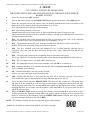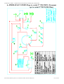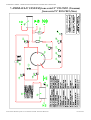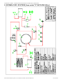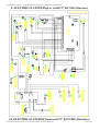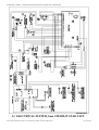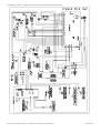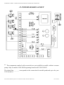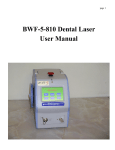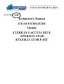
1
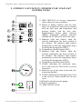
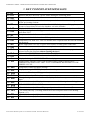
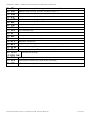
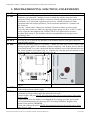
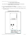
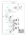
COMPANY WITH CERTIFIED QUALITY SYSTEM
UNI EN ISO 9002 & EN 46002
MEDICAL APPLIANCE DIVISION
Cod. 3413
GB
Technician's Manual
STEAM STERILIZERS
Models
STERILIX VACUUM PLUS
STERILIX STAR
STERILIX STAR FAST
Technician’s manual – Steam sterilizers mod. Sterilix Vacuum Plus e Sterilix Star
Table of contents:
1. VACUUM PLUS / STAR / STAR FAST.............. CONTROL PANEL…………..… 3
2. KEY TO DISPLAYED MESSAGES ……………………………………………...… 4
3. TROUBLESHOOTING: SOLUTIONS AND REMEDIES………………………….6
4. OPERATION OF THE 121° - 134° CYCLES………………………………….....….9
5. TESTS………………………………………………..…………………………..…...10
6. HYDRAULIC SYSTEM up to serial N°……………...…..…………………..….…. 11
7. HYDRAULIC SYSTEM from serial N°…………………….………………………. 12
8. HYDRAULIC SYSTEM from serial N°…………………….………………………. 13
9. ELECTRICAL SYSTEM up to serilal N°……………....………..……………....…. 14
10. ELECTRICAL SYSTEM from serial N°………..…..……………….………....…. 15
11. ELECTRICAL SYSTEM from STERILIX STAR FAST...………….………....…. 16
11. POWER BOARD LAYOUT …… ………...………………………………….……. 17
12. ADJUSTMENT PRINT-OUT …….………………………………………………..18
13. FIG. 1 ……………………………………………………………………………….19
E:\Documenti1\Manuali superati non in uso\MANUALE DEL TECNICO GB-R03.doc
P. 2 of 19
Technician’s manual – Steam sterilizers mod. Sterilix Vacuum Plus e Sterilix Star
1. STERILIX VACUUM PLUS / STERILIX STAR / STAR FAST
CONTROL PANEL
1) INFO DISPLAY for set-ups, temperature
values and cycle time in minutes.
2) Button to deduct minutes with the door
open, for temperature and pressure display
with the door open and temperature and
pressure display with the door shut.
Supplementary drying phase selection
(DRY). Fractioned vacuum selection
(STERILIX STAR and STAR FAST only).
3) Indicator light that flashes when the
selected temperature has been reached in
the chamber. The indicator light remains
permanently on when the temperature drops
or during the drying phase (DRY).
4) Temperature selection button (PR1).
5) Indicator light that flashes when the
selected temperature has been reached in
the chamber. The indicator light remains
permanently on when the temperature drops
or during the drying phase (DRY).
6) Temperature selection button (PR2).
7) Telltale indicating the maximum water
level in the reservoir. OK for next cycle not
fractioned.
8) Button to top up the water in the tank (see
instruction manual).
9) Telltale indicating the minimum water level
in the reservoir. Water insufficient for next
cycle.
10)Chamber internal pressure gauge.
11)Printer connection.
12) Main ON/OFF switch.
E:\Documenti1\Manuali superati non in uso\MANUALE DEL TECNICO GB-R03.doc
P. 3 of 19
Technician’s manual – Steam sterilizers mod. Sterilix Vacuum Plus e Sterilix Star
2. KEY TO DISPLAYED MESSAGES
01 - tPt
02 - rEt
03 - dor
04 - SLP
05 - Ptl
06 - btP
07 - PrS
08 - otr
09 - Lot
10 - nPt
11 - Hit
12 - dPr
13 - Pr0
14 - Pr1
15 - Pr2
16 - A-
17 - Str
18 - 888
19 - StP
20 - H2o
21 - FuL
22 - PrE
23 - tEP
24 - End
25 - PuP
26 - rES
27 - Elb
28 - Elc
Indicates a block status.
Indicates that there has been a power failure during the sterilizing phase.
The user is asked to open the door
Displayed after 1 hour, when the door is open and the machine is not being used: turns
off the pre-heating element.
Indicates that the temperature is less than 110°C during the sterilizing phase, with a
pressure of more than 0.8 bar in the chamber: air in the chamber.
Displayed if 35 min. have elapsed and the temperature has not reached at least 115°C.
Displayed during the sterilizing process: Pressure less than 0.8 bar with a temperature of
more than 120°C
Temperature in the boiler more than 142°C.
Temperature in the boiler less than -5°C or probe broken.
Temperature less than 50°C once 20 minutes have elapsed from the time the machine
was powered.
Boiler temperature over 160° or probe wire broken, or faulty probe connection.
The machine has not carried out the vacuum phase.
This message is displayed at the beginning of the cycle when no program has been
selected (select the program without opening the door).
Indicates that PROGRAM 1 has been selected. (134°)
Indicates that PROGRAM 2 has been selected. (121°)
Displayed during the DRYING PHASE: A = drying.
STERILIZED: indicates THAT THE STERILIZING OPERATIONS HAVE
TERMINATED AND THAT THE CYCLE CONFORMS. BEGINNING OF THE
UPKEEP CYCLE.
Temperature control test phase message.
Displayed during the PRINT phase (even when the printer is not connected).
No water in fill tank (see filling procedure).
Water level in tank sufficient for next cycle.
Message lasting a few seconds. Precedes display of chamber temperature with door open
alone.
( For technicians only ): Displays the temperature reached during the sterilizing phase.
END OF STERILIZING CYCLE.
( For technicians only ): Water fill pump only activated in test function. (7)
( For technicians only ): Heating element on to test real power draw of the heating
element. (13)
( For technicians only ): N.O. solenoid. (14)
( For technicians only ): Chamber water inlet solenoid valve. (7+16)
E:\Documenti1\Manuali superati non in uso\MANUALE DEL TECNICO GB-R03.doc
P. 4 of 19
Technician’s manual – Steam sterilizers mod. Sterilix Vacuum Plus e Sterilix Star
( For technicians only ): Draining solenoid valve shut. (15)
29 - ElS
Machine status message. Pressure less than 0.8 bar. (1)
30 - PoF
Machine status message. Pressure higher than 0.8 bar. (1)
31 - Pon
Machine status message. Sufficient water in tank.
32 - S.L
33 - APE Machine status message. Door open.
Machine status message. Water below minimum level.
34 - noL
Door shut.
35 - CH.
For technicians only.
36 - SCr
For technicians only.
37 - LEt
Makes sure that the microprocessor is not faulty.
38 - SI
Microprocessor error
39 - Err
On ( electronic board powered ).
40 - - - 41 -ACU Maximum vacuum test.
Supplementary drying program to select after the sterilizing cycle has terminated.
42 - drY
43 - oCH Vacuum OK message. There are no leaks in the hydraulic circuit of the machine.
44 - LLn Vacuum faulty message. There are leaks in the hydraulic circuit of the machine.
Vacuum test message.
45 - TEST
VUOTO OK
46 - USd Message indicating dirty water in machine.
47 - FrA Fractionated vacuum with 3 peaks before sterilizing
( For technicians only ): Vacuum pump N. C. solenoid
48 - ElP
E:\Documenti1\Manuali superati non in uso\MANUALE DEL TECNICO GB-R03.doc
P. 5 of 19
Technician’s manual – Steam sterilizers mod. Sterilix Vacuum Plus e Sterilix Star
3. TROUBLESHOOTING: SOLUTIONS AND REMEDIES
01- tPt
02- rEt
03- dor
04- SLP
05- PtL
Repeat the sterilizing process or contact the after-sales service center.
Wait until the power supply returns. Check the socket and replace it if necessary.
Eliminate any reductions / multiple sockets to which the machine may have been
connected. Keep electronic machines well away from the appliance as they may create
disturbance (e.g. ultrasound equipment, microwaves, cellular telephones or other
equipment that emit radio frequencies). Do not touch the machine for 3 minutes wih
the switch on.
Once the 3 minutes have elapsed, the machine will make a double acoustic signal.
Leave the main switch on. Make sure that the pressure gauge needle is on the “0” mark
(zero). Open the door and keep the “DEDUCTION” key depressed for at least 5
seconds, then release it. The machine will reset automatically now to begin a new
sterilizing cycle.
Wait until the message stops flashing and then open the door.
Press any key to re-activate the functions if the machine must be used again, otherwise
switch off the machine.
Repeat the sterilizing process if necessary. Contact the after-sales service center if the
message appears again. If the machine remains completely cold despite the fact that the
green main switch is on, this could mean that the manually reset safety thermostat at the
rear of the machine has tripped (fig. A). Unscrew the cap and press the button on the
thermostat. Make sure that it trips and resets (fig. B).
Fig.B
Open the machine and repeat the sterilizing process. Contact the after-sales service
center if the message appears again.
- there may be a short-circuit in the N.O. solenoid valve coil: replace the coil.
- jamming or foreign bodies under the solenoid valve seals.
Clean or replace the part. NOTE: this operation must only be carried out by After-sales
Service staff.
- water fails to enter the chamber even though the level gauge gives the green signal.
- the internal temperature governor type PT 100 is badly calibrated. Regulate it by
means of the internal TRIMMER.
Check and calibrate the probe: NOTE: this operation must only be carried out by Aftersales Service staff.
Fig.A
06- btP
07- PrS
E:\Documenti1\Manuali superati non in uso\MANUALE DEL TECNICO GB-R03.doc
P. 6 of 19
Technician’s manual – Steam sterilizers mod. Sterilix Vacuum Plus e Sterilix Star
08- otr
09- Lot
10- ntP
11- HIt
12- dPr
44- LLn
19- StP
20- H2o
39- Err
42- drY
46- USd
Check and calibrate temperature probe type PT 100: NOTE: this operation must only be
carried out by After-sales Service staff.
Autoclave on in a cold room: heat the room or check to make sure that the probe
operates correctly.
- The wire of the heating element has probably detached.
- Burnt-out heating element.
- The connection does not conform to the heating element.
- Faulty TRIAC: check the connections with a multimeter and replace the part if
necessary. Use a genuine spare part and take great care to make the connections in the
correct way. NOTE: this operation must only be carried out by After-sales Service
staff.
Temperature too high:
- Check and calibrate temperature probe type PT 100: NOTE: this operation must only
be carried out by After-sales Service staff.
- Faulty TRIAC: check the connections with a multimeter and replace the part if
necessary. Use a genuine spare part and take great care to make the connections in the
correct way.
A wire of temperature probe type PT 100 has broken: check the connection terminal
and replace the probe with a genuine spare if necessary.
NOTE: both these operations must only be carried out by After-sales Service staff.
Too much moisture in the chamber before the sterilizing cycle starts: after having
opened the door, deactivate the alarm by pressing the selected program for 3 sec., then
repeat the cycle.
Contact the After-sales Service Center if the fault occurs again.
Check all the vacuum pump pipes. Replace them with genuine spares if they are
damaged.
Check all the solenoid valves to make sure that there are no leaks and clean and/or
replace the cores if necessary. NOTE: this operation must only be carried out by the
After-sales Service staff.
Check whether the pressure gauge pointer drops below –0.45 Bar because this means
that there is certainly a vacuum in the chamber and that the pressure switch setting
must therefore be checked.
Connect the printer used to check and file the data.
Fill the tank with distilled or demineralized water using the supplied accessories.
( For technicians only ): Repeat the microprocessor re-generating process.
Supplementary drying cycle repeatable several times. To use when normal drying has
not been sufficient. Press DEDUCT with the door open to select the supplementary
drying cycle. The cycle lasts 9 minutes.
Connect the supplied tube to the red cock and turn it on. This drains the used water
from the tank. The autoclave will accept no cycle when this message is displayed.
Remember to turn off the cock after the tank has drained.
E:\Documenti1\Manuali superati non in uso\MANUALE DEL TECNICO GB-R03.doc
P. 7 of 19
Technician’s manual – Steam sterilizers mod. Sterilix Vacuum Plus e Sterilix Star
4. OPERATION OF THE 121° - 134° CYCLES
THE INDICATED POSITIONS ARE ILLUSTRATED IN THE ENCLOSED
HYDRAULIC LAYOUT AND WIRING DIAGRAM
1
Once the program has been selected, the machine will start by means of door micro
pos. 4. The temperature on the display must be less than 90°.
The vacuum pump pos. 12 comes on and the N.C. solenoid valve pos. 18 is
activated for about 3 minutes until it is deactivated by the pressure switch pos. 3.
Meanwhile, N.O. solenoid pos. 14 closes.
2
If a vacuum error (dPr) is not signalled, the N.C. solenoid valve pos. 16 opens and
water is injected into the chamber pos. 4 for about 15 seconds by means of the
vibration pump pos. 7. The N.O. solenoid valve pos. 14 remains closed during this
operation.
3
By heating, the heating element pos. 13 transforms the water in the chamber into
vapour and pressurizes it. When there is air in the chamber, the pressure gauge
pointer may drop to zero after which the pressure reading will increase until the
selected temperature has been reached. To obtain saturated vapour, the N.C.
solenoid valve pos. 15 vents off the air intermittently.
4
The pressure switch pos. 1 must trip at a temperature between 111°C and 119°C.
Failing this, one of the following errors: PrS/PtL will appear on the display.
5
The pressure should be 1.1 bar once a temperature of 121°C has been reached.
The pressure should be 2.1 bar once a temperature of 134°C has been reached.
The pressure will be 0.2-0.3 bar lower when the chamber is empty (with no tray
holders).
6
Press the PUMP key when the machine is on and the door shut and the display will
visualize two data items: Pon, the pressure is higher than 0.8 bar. PoF, the pressure
is less than 0.8 bar.
This control is also enabled when the machine is preparing for the sterilizing phase.
Keep the PUMP key pressed for more than 5 seconds to print out the temperature in
the chamber in real time.
7
If the temperature is 1.5°C higher than the selected value, the N.C. solenoid valve
pos. 15 will relieve vapour in order to bring the temperature and pressure down to
lower values.
8
Once the sterilizing time has terminated, the condensation discharge phase starts by
means of the N.O. solenoid valve pos. 14 which, with the aid of the pressure in the
chamber, sucks up all the water from the bottom in intermittent mode for about one
minute. The condensation extracted from the chamber passes through the cooling
coil pos. 10 and reaches the used water reservoir pos. 9.
E:\Documenti1\Manuali superati non in uso\MANUALE DEL TECNICO GB-R03.doc
P. 8 of 19
Technician’s manual – Steam sterilizers mod. Sterilix Vacuum Plus e Sterilix Star
9
Once the draining phase has terminated, the N.O. solenoid valve pos. 14 closes for
about two minutes to allow a vacuum to form in the chamber by means of the pump
pos. 12.
Once the two minutes have elapsed, the N.C. solenoid valve pos. 17 trips
intermittently and, thanks to connection with the bacteriological filter pos. 13,
allows air to pass and the chamber interior to dry. During this phase (dry cycle), the
message on the display will be A- with the number of cycle minutes still remaining
alongside.
10
If the pressure exceeds 2.2 bar during the sterilizing phase, the pressure switch pos.
2 allows the N.C. solenoid valve pos. 15 to open and thus relieve the excess
pressure.
11
If the H2o message appears on the display and the red minimum indicator light is
on, the fill pump pos. 7 should start when the PUMP key is pressed with the door
open. If this fails to occur, the door micro pos. 4 is probably signalling door closed
even if the door is open.
12
After sterilizing, the upkeep cycle starts with the Str signal, so long as the door is
not opened. The vacuum pump pos. 12, the N.C. solenoid valve pos. 18, the N.O.
solenoid valve pos. 14 and the N.C. solenoid valve pos. 17 start operating in order
to bring the temperature in the chamber to between 80° and 120°.
E:\Documenti1\Manuali superati non in uso\MANUALE DEL TECNICO GB-R03.doc
P. 9 of 19
Technician’s manual – Steam sterilizers mod. Sterilix Vacuum Plus e Sterilix Star
5. TESTS
TO CONDUCT WITH THE DOOR OPEN.
THE INDICATED LEDS ARE ILLUSTRATED IN THE ENCLOSED POWER
BOARD LAYOUT
1
Leave the switch in the OFF position.
2
Turn on the switch along with the DEDUCTION button and only release it when 888 appears.
3
Either the program version will appear (only for models manufactured in the year 2000) or the
temperature in the chamber at that precise moment (e.g. 59-60).
Press intermittently after having read the message.
4
rES - The heating element is powered.
If led N° 10 on the power board comes on, this means that the signal is being received.
Make sure that the heating element is actually heating by placing your hand inside the reservoir or
an amperometric instrument.
5
ELI - The solenoid valve of the bacteriological filter is on. Listen for the "tick" noise indicating
that the solenoid valve has activated and make sure that led N° 7 is on.
6
ELC - The pump that draws the water from the fill tank is on and delivers water to the boiler.
Led N° 3 will come on and the pump can be heard to operate.
7
ELb - The N.O. solenoid valve near the condenser is on. To check that the solenoid valve is
energized, close and open the door and listen for the "tick" noise. Make sure that led N° 9 is
always on.
8
ELP – Vacuum pump solenoid valve beginning from serial number 00131004
The 3-way solenoid valve and the vacuum pump will be independent and led N° 6 will come on.
9
ELS - The air exhaust valve is on and Led N° 4 remains on.
10
PUP - The pump that delivers water to the chamber is on and led N° 1 remains on.
11
PoF - Indicates that there is no pressure and that the wires of pressure switch N° 1 are not in the
exact "normally open" position.
12
noL - Indicates that there is no water in the fill tank.
If there was water, the signal would be S.L No led.
13
APE - Signals that the door is open and that the door micro operates correctly. If the door is
closed when this signal is displayed, the message Ch must appear. No led on.
14
Leave the door closed and press DEDUCTION. This activates the vacuum test. The pump starts
and leds N° 9, N° 6 and N° 2 come on. The pressure gauge reading must drop below zero after
which the pump must stop. The message OCh must appear on the display after about 3 minutes,
meaning that there are no leaks from the machine. After this, led N° 2 will go out and leds N° 9
and N° 6 will remain on.
15
When the DEDUCTION button is pressed, the vacuum is relieved, led N° 7 will remain on for 5
seconds and then the flashing message STP will appear. All the messages will be printed if the
printer is connected at that moment. Press the DEDUCTION button with the door open to reset
any error message (with the exclusion of RET).
NOTE: The boldface captions are the messages that appear on the display.
Led N° 6 is installed on models from serial N° 00131004 onwards.
E:\Documenti1\Manuali superati non in uso\MANUALE DEL TECNICO GB-R03.doc
P. 10 of 19
Technician’s manual – Steam sterilizers mod. Sterilix Vacuum Plus e Sterilix Star
6. HYDRAULIC SYSTEM up to serial N° 99125091 (Vacuum)
up to serial N°99131003(Star)
E:\Documenti1\Manuali superati non in uso\MANUALE DEL TECNICO GB-R03.doc
P. 11 of 19
Technician’s manual – Steam sterilizers mod. Sterilix Vacuum Plus e Sterilix Star
7. HYDRAULIC SYSTEM from serial N° 99125092 (Vacuum)
from serial N° 00131001 (Star)
E:\Documenti1\Manuali superati non in uso\MANUALE DEL TECNICO GB-R03.doc
P. 12 of 19
Technician’s manual – Steam sterilizers mod. Sterilix Vacuum Plus e Sterilix Star
8. HYDRAULIC SYSTEM from serial N° 00131004 (Star)
E:\Documenti1\Manuali superati non in uso\MANUALE DEL TECNICO GB-R03.doc
P. 13 of 19
Technician’s manual – Steam sterilizers mod. Sterilix Vacuum Plus e Sterilix Star
9. ELECTRICAL SYSTEM up to serilal N° 00131003 (Starclave)
10. ELECTRICAL SYSTEM from serial N° 00131004 (Starclave)
E:\Documenti1\Manuali superati non in uso\MANUALE DEL TECNICO GB-R03.doc
P. 14 of 19
Technician’s manual – Steam sterilizers mod. Sterilix Vacuum Plus e Sterilix Star
11. ELECTRICAL SYSTEM from STERILIX STAR FAST
E:\Documenti1\Manuali superati non in uso\MANUALE DEL TECNICO GB-R03.doc
P. 15 of 19
Technician’s manual – Steam sterilizers mod. Sterilix Vacuum Plus e Sterilix Star
E:\Documenti1\Manuali superati non in uso\MANUALE DEL TECNICO GB-R03.doc
P. 16 of 19
Technician’s manual – Steam sterilizers mod. Sterilix Vacuum Plus e Sterilix Star
12. POWER BOARD LAYOUT
*
The components marked with an asterisk are not available in models without vacuum
pump. Only in models 1999-2000 beginning from Serial N°991250092
The dotted line_ _ _ _ _ corresponds to the connection for models produced up to the year
1999 inclusive.
E:\Documenti1\Manuali superati non in uso\MANUALE DEL TECNICO GB-R03.doc
P. 17 of 19
Technician’s manual – Steam sterilizers mod. Sterilix Vacuum Plus e Sterilix Star
13. ADJUSTMENT PRINT-OUT
THIS OPERATION CAN BE CARRIED OUT ON AUTOCLAVES WITH SERIAL
NUMBERS FROM 99091000 ONWARDS.
1) Power the printer and connect it to the machine.
2) Turn on the green main switch. Press the DEDUCT and PUMP buttons at the same
time.
3) The report of the last 50 operations carried out and the signals displayed will be
automatically printed.
TEMPERATURE ADJUSTING
E:\Documenti1\Manuali superati non in uso\MANUALE DEL TECNICO GB-R03.doc
P. 18 of 19
Technician’s manual – Steam sterilizers mod. Sterilix Vacuum Plus e Sterilix Star
14. FIG.1
E:\Documenti1\Manuali superati non in uso\MANUALE DEL TECNICO GB-R03.doc
P. 19 of 19