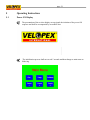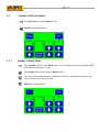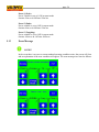
1
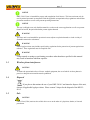
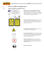
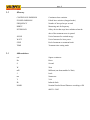
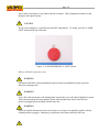
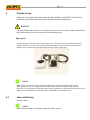
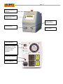
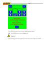
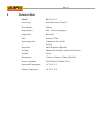
page 1 BWF5810 Dental Laser User Manual page 2 TABLE OF CONTENT 1 WARNING AND SAFETY INFORMATION .......................................................................................................................4 1.1 1.2 1.3 1.4 1.5 2 GLOSSARY, SYMBOLS AND ABBREVIATIONS .............................................................................................................6 2.1 2.2 2.3 3 SYMBOLS AND LABELS ON THE BWF58105 ...................................................................................................................6 GLOSSARY .......................................................................................................................................................................8 ABBREVIATIONS...............................................................................................................................................................8 INTRODUCTION ..................................................................................................................................................................9 3.1 3.2 3.3 3.4 4 HIGHLIGHTING OF WARNING AND SAFETY INFORMATION ...................................................................................................4 INTENDED USE .................................................................................................................................................................4 WIRELESS PHONE INTERFERENCE ......................................................................................................................................5 DISPOSAL ........................................................................................................................................................................5 SALE................................................................................................................................................................................5 CLASSIFICATION ..............................................................................................................................................................9 SAFETY PRECAUTIONS ......................................................................................................................................................9 TRANSPORT AND STORAGE .............................................................................................................................................12 PRECAUTIONS ................................................................................................................................................................12 SYSTEM SETUP ................................................................................................................................................................15 SPARE PARTS ................................................................................................................................................................................15 4.1 LASER UNIT SETUP ........................................................................................................................................................15 4.2 FIBER INSTALLATION ......................................................................................................................................................18 4.3 CONNECTION OF THE FOOT CONTROL ..............................................................................................................................18 4.4 SWITCHING THE LASER UNIT ON AND OFF ........................................................................................................................18 4.5 OPTICAL FIBER PREPARING ............................................................................................................................................19 5 OPERATING INSTRUCTIONS..........................................................................................................................................21 5.1 5.2 5.3 5.4 5.5 5.6 5.7 5.8 5.9 5.10 5.11 5.12 5.13 6 CLEANING AND STERILIZATION..................................................................................................................................28 6.1 6.2 6.3 6.4 7 POWER ON DISPLAY ......................................................................................................................................................21 STANDBY AND READY DISPLAY ......................................................................................................................................22 LASER POWER SETTING .................................................................................................................................................23 CW MODE ....................................................................................................................................................................23 SINGLE PULSE MODE .....................................................................................................................................................23 REPEAT PULSE MODE ....................................................................................................................................................23 LASER EMISSION ENERGY RESET ....................................................................................................................................24 SETUP MODE................................................................................................................................................................24 PRESET PROGRAMMING ..................................................................................................................................................25 EMISSION MODE ............................................................................................................................................................25 STOP EMISSION ..............................................................................................................................................................25 PRESET MODE ................................................................................................................................................................25 ERROR MESSAGE ...........................................................................................................................................................26 CLEANING......................................................................................................................................................................28 DISINFECTION ................................................................................................................................................................29 STERILIZATION ...............................................................................................................................................................29 CLEANING OF THE LASER UNIT ........................................................................................................................................30 MAINTENANCE AND SERVICE ......................................................................................................................................31 7.1 7.2 7.3 SAFETY CHECKS .............................................................................................................................................................31 MAINTENANCE ...............................................................................................................................................................31 BASIC TROUBLESHOOTING ..............................................................................................................................................32 page 3 7.4 TECHNICAL SUPPORT ......................................................................................................................................................32 8 TECHNICAL DATA............................................................................................................................................................33 9 WARRANTY INFORMATION...........................................................................................................................................34 TERMS AND CONDITIONS ..............................................................................................................................................................34 page 4 1 Warning and Safety Information 1.1 Highlighting of warning and safety information To prevent any personal injury or material damage, please observe the warning and safety information provided in the present operating instructions. All such information is highlighted as follows: NOTICE For additional information CAUTION If there is any risk of damage to the laser unit WARNING If there is any hazard to the life or health of persons This symbol indicates that you have to take action This symbol indicates that a certain result will occur 1.2 Intended use NOTICE The user should read and be thoroughly familiar with this manual before operating the instrument. The equipment should be routinely inspected and maintained in accordance with the instructions given in the maintenance section of this manual. Accidental irradiation to other than the target tissue may result in laser burn. Surrounding the target area with moist drapes or salinesoaked gauze pads and keeping them moist will greatly reduce these hazards. Be sure the draping is appropriate for laser surgery. It is recommended that a smoke evacuator or inline filter be used to capture the plume whenever possible. The plume should be regarded as source of active biological material by the operating room personnel; it may contain viable tissue particulates. NOTICE Nominal Ocular Hazards Distance (NOHD) is 1.5 m from the distal end of the fiber NOTICE For the installation and use of the BWF58105, Velopex requires: · Compliance with IEC 608251 and its amendments · Compliance with any additional national laws and ordinances page 5 NOTICE BWF58105 laser is intended for surgery and coagulation of soft tissues. This laser unit must only be used by trained personnel in compliance with the applicable occupational safety regulations and accident prevention measures as well as the present operating instructions. NOTICE The user is obliged to use only faultless materials, to observe the correct application as well as to protect himself or herself, the patient and other persons against hazards. WARNING This laser unit is not intended for operation in areas subject to explosion hazards or in the vicinity of flammable materials or substances. WARNING Public legal provisions may include special safety regulations for the protection of persons against laser radiation. These regulations must be complied with. WARNING Using controls or settings or performing procedures other than those specified in this manual may result in hazardous radiation exposure. 1.3 Wireless phone interference CAUTION To ensure the operational safety of electro medical equipment, the use of mobile wireless phones in practice or hospital environments must be prohibited. 1.4 Disposal If you plan to discontinue the use of your BWF58105 and intend to dispose of the unit, observe all applicable legal provisions. Please contact Velopex for the disposal of the BWF5 8105. 1.5 Sale CAUTION Federal Law (USA) restricts sales of this device to or on the order of a physician, dentist, or licensed practitioner. page 6 2 Glossary, Symbols and Abbreviations 2.1 Symbols and labels on the BWF58105 Manufacturer’s General Identification Label (See Figure) Located on the side of the device. The label displays the manufacturer, model number, serial number, date of manufacture of the unit. This label also presents various regulatory compliance declarations. General Safety Declaration Label (See Figure) Located on the side of the device, this label indicates the laser classification. It warns of the radiation exposure hazard potential to eyes and skin. Laser Radiation warning Label (See Figure) Located at the top center of the front faceplate. Laser Emission (Aperture) Located on the front of the device, the laser emission (Aperture) label indicates that the laser energy emission occurs at the distal end of a properly connected optical fiber. Warranty Seal Label (See Figure) These labels are positioned on the underside of the laser device in such a way that any attempt to open the panels of this device will break this seal. STOP Emergency Stop switch page 7 CE mark in accordance with Council Directive 93/42/EEC, stating the manufacturer’s Notified body Type BF device EU representative Manufacture Read instruction ! Please refer to the user manual The symbol indicating separate collection for electrical and electronic equipment SN Product Series Number Foot Switch Interlock page 8 2.2 Glossary CONTINUOUS EMISSION Continuous laser emission PULSED EMISSION Pulsed laser emission (chopped mode) FREQUENCY Number of laser pulses per second HERTZ Measuring unit for frequency INTERLOCK Safety device that stops laser radiation when the door of the treatment room is opened 2.3 JOULE Unit of measure for emitted energy WATT Unit of measure for laser power STOP End of treatment or treatment break TIME Treatment time setting mode Abbreviations cm² Square centimeter Hz Hertz S Second W Watt mW Milliwatt (one thousandth of a Watt) J Joule nm Nanometer V Volt IR Infrared diode NOHD Nominal Ocular Hazard Distance according to EN 608251: 2003 page 9 3 Introduction 3.1 Classification According to the applicable standards, the BWF58105 laser is classified as follows: · Class I Type B device according to EN IEC 606011:1990 + A1:1993 + A2:1 1995 plus amendments · Class IIb according to Council Directive 93/42/EEC · Class IV laser product according to IEC 608251 plus amendments · Degree of protection according to EN IEC 606011:1990 + A1:1993 + A2:1 1995 plus amendments: medical unit: IP 20 (enclosure not waterproof); foot control: IPX7 CAUTION The laser unit itself cannot be sterilized. However, some accessories must be sterilized when used for contact applications. WARNING The laser unit is not suitable for use in the presence of anesthetics that are flammable when in contact with air, oxygen or nitrogen monoxide. 3.2 Safety precautions BWF58105 laser is manufactured in compliance with the provisions of Council Directive 93/42/EEC concerning medical devices (MDD). Always observe the following precautions: WARNING Always cover the optical fiber connection with the special protection caps provided, if the fiber is disconnected from the laser. CAUTION Use of the operating controls or adjustment options in a way other than described herein can lead to dangerous radiation. CAUTION page 10 Never insert your fingers or any objects into the exit ports. This is important in order to avoid damage to the optical system. CAUTION In case of an emergency, switch the laser unit OFF immediately. To do this, press the “LASER STOP” button on the top of the unit. Figure 1: “LASER EMERGENCY STOP” button Observe all labels on the laser unit WARNING Operation of this laser unit by unauthorized persons must be prohibited in order to prevent incorrect or improper use. WARNING Never direct the laser beam or the aiming beam towards the eyes or the thyroid gland of a person. All persons present in the room (patient, doctor and assistant) must always wear the laser protective goggles delivered along with the laser unit. WARNING Never use optical instruments such as microscopes, eye loupes or magnifiers together with the original protective goggles. Adequate eye protection is no longer ensured in this case. page 11 CAUTION Always cover the optical fiber connection with the special protection caps provided. WARNING The unit is not suitable for use in the presence of anesthetics that are flammable when in contact with air, oxygen or nitrous oxide. WARNING Oxygensaturated materials such as cotton wool can catch fire due to the high temperature that the unit reaches during operation. Label removers and flammable solutions used for cleaning and disinfecting the laser unit should be allowed to evaporate before using the device. Be aware of the fire risk caused by flammable gases. WARNING Never direct the laser beam toward paper, plastics or dark surfaces. They may catch fire or be damaged due to the high temperatures produced by the laser beam. WARNING Laser plume must contain tissue particles. There is a risk of contamination! Always wear a face mask. Observe the following in addition: NOTICE The unit must only be operated in rooms that comply with requirements of Council Directive 89/336/EEC. The applicable national or local legal regulations must be complied with. CAUTION Avoid interference of the laser emission with optical sensors of devices operated in the vicinity of the BWF58105 laser. page 12 3.3 3.3.1 Transport and storage Transport and storage The BWF58105 laser is supplied in a case that ensures proper and easy transport. However, please observe the following: Do not leave the laser unit in a car parked in the sun. The temperature inside the car can reach levels that may damage its components. To ensure appropriate storage, the laser unit must always be kept in the case supplied. When stored in the case provided by Velopex, the BWF58105 laser withstands the following environmental conditions: · Temperatures from 20ºC (4ºF) to +70ºC (+158ºF) · Relative humidity from 10% to 90% When stored in its original transport packing, the BWF58105 laser withstands the following environmental conditions: · Temperatures from 20ºC (4ºF) to +70ºC (+158ºF) · Relative humidity from 10% to 95% 3.3.2 Operating conditions The BWF58105 laser may be operated in the following environmental conditions: · Temperatures from +10ºC (+50ºF) to +35ºC (+95ºF) · Relative humidity from 10% to 95% CAUTION Following transport and storage, allow the laser unit to acclimate for about hour in order to reduce the risk of malfunction due to condensation. 3.4 Precautions Using controls or settings or performing functional tests other than those specified in this manual may result in hazardous radiation exposure. Velopex can not be held liable for any damage caused by improper use or noncompliance with the instructions and information provided in this manual. Please remember the following: CAUTION BWF58105 laser may only be operated by trained and qualified personnel. page 13 CAUTION Laser equipment not in use must be protected against unauthorized access. This can be achieved by switching off the laser unit after use, so that the electronic access key must be entered prior to further operation. Set up the BWF58105 laser unit properly and completely before putting it into operation (See Chapter 4) Make sure that the electrical system is equipped with the required devices for protection against direct and indirect contact (thermo magnetic switches, residual current circuitbreaker) and has been set up by a qualified electrician in compliance with the applicable IEC standards. National regulations concerning electrical installations shall be obeyed. Verify that the line voltage corresponds to the voltage indicated on the rating plate of the switching power supply or in the technical specifications. WARNING Do not use the laser unit if a visual inspection reveals damage. WARNING Do not use the laser unit in the presence of flammable materials. If you accidentally spill liquid on the unit, immediately stop treatment, disconnect the power supply cable and contact your local distributor or authorized service center for assistance. CAUTION Never attempt to disassemble the laser unit. This is limited exclusively to the manufacturer. Do not place the laser unit near heat sources. Do not cover the convection openings for air cooling on the back of the unit. CAUTION Always protect the optical fiber socket as well as the optical fiber itself with the special protection caps. Do not allow dust, dirt or other foreign bodies to enter the optical fiber socket. Always make sure that the optical system is clean before connecting the optical fiber. page 14 WARNING Prior to each treatment, the hand pieces must be sterilized and the optical fibers must be steam sterilized. page 15 4 System Setup If national or local legal regulations require that the installation of the BWF58105 laser be performed by specialized personnel, these regulations must be complied with. WARNING The optical fibers and hand piece are supplied nonsterile, you must clean, disinfect and sterilize these products prior to first use and prior to each subsequent use. Spare parts A single intensity footswitch comes with this laser device. The laser device treats the footswitch as a simple on/off device. Pressing down on the footswitch produces 100% of the laser energy set by the operator. Fully releasing the pressed footswitch stops laser energy generation. NOTICE When closed, the cover of the foot switch is designed to prevent inadvertent foot pedal control. When the laser is properly configured and all safety features have been complied with, open the footswitch cover by pressing it fully down then releasing. Disable laser emission and/or turn power off to further prevent inadvertent laser activation due to unattended foot switch depression. 4.1 Laser unit Setup Setup Location NOTICE Ensure that the surface will properly support the entire system. page 16 NOTICE Place within 6 feet of an available 110~240V electrical outlet NOTICE Ensure adequate airflow around the system · Open the box. · Remove the protective packaging cover. · Locate and keep this manual in a secure location. · Remove any intermediate protective packaging material. · Remove the power supply and power cord. · Remove the laser system. · Select a flat surface (not a surface that will inhibit airflow through the base of the system) · There must be a minimum 4” (10 cm) clearance around the rear of the system page 17 Laser emission LED indicator Display and control touch screen Power on/off LED indicator Emission port Key switch Safety interlock Optional I/O terminal. Manufacture use only. DO NOT connect anything to this terminal. Footswitch connector Power connector page 18 WARNING The optional I/O terminal is only for manufacture use only. DON’T connect anything to this terminal 4.2 Fiber Installation WARNING Please follow the recommend sterilization condition to sterilize the optical fiber before laser surgery. Use of a nonsterilized optical fiber to perform surgery may cause serious infection. Only standard SMA905 connector can be used with the BWF58105 laser in the spectral range of 810nm+/10nm. If the optical fibers from other manufacturers are used, physical properties, such as tensile and transmission behavior, may vary. For this reason, Velopex assumes no liability in such cases. WARNING 400um (or larger) core size with 0.37NA silicon core silicon cladding optical fiber with Use Velopex or CE marked Medical Grade optical fiber only. 4.3 Connection of the foot control Uncoil the footswitch. Connect the footswitch to the laser unit on the rear. 4.4 Switching the laser unit on and off Locate and uncoil the AC power cord. Plug the power cord into the AC input on the rear of the laser system. Plug the male end of the AC power cord into an available electrical outlet. Insert the safety interlock into position. Insert one of the keys into the keylock switch located the front of the system. page 19 Turn the key clockwise to the right onequarter turn. WARNING The key can only be inserted into and removed from the key switch when it is in the vertical (standby) position. The fan will start. There will be an audible beep and the LCD panel will illuminate displaying the initial startup splash screen. Refer to the Operation Section to configure and operate the system. 4.5 Optical fiber preparing WARNING Always avoid pointing the aiming beam at of anyone’s eyes. It is an intense light source even at lower power levels! Wear laser protective goggles! Check whether the aiming beam signal is an evenly illuminated, roundshaped pattern. To do this, aim the tip of the probe vertically at a white background located approx 15cm away. If there is no beam pattern at all or the beam pattern of the laser probe is unevenly illuminated, the fiber may be damaged or broken. In this case, send the laser fiber in to your distributor for exchange under warranty. Do not use damaged optical fibers. If the aiming beam signal produces a nonevenly illuminated beam pattern, cut the fiber off with the fiber cleaver until an evenly illuminated round pattern has been obtained. CAUTION If you switch on the laser unit and the signal of the red aiming laser is not visible or you cannot see the aiming beam during the treatment, proceed as follows: Turn off the laser and check the optical fiber as well as the fiber connection for mechanical damage. If the optical fiber is damaged, replace it with a new one. Check the setting to make sure the aiming is not set at OFF selection. page 20 If you cannot detect any damage on the optical fiber and the aiming setting is not at OFF but the signal of the aiming laser is not visible with the new optical fiber either, turn off the laser and contact BWTEK, your local distributor or your authorized service center. CAUTION The optical fiber must be sterilized prior to the first treatment. page 21 5 Operating Instructions 5.1 Power ON Display The presentation of the revision display screen signals the initiation of the power ON sequence and shall be accompanied by an audible alert. The initialization process shall not exceed 5 seconds and then change to main menu as following. page 22 5.2 Standby and Ready Display Press Run button to enter Standby mode. Standby screen presentation. 5.2. 1 Standby to Ready Mode Press Standby button to enter Ready mode. A sixsecond laser emission enabling audible alert notification sequence occurs. The Standby button shall change to Ready button. The laser will be enabled upon the completion of the laseremission alert sequence and occur when the footswitch is pressed. Ready screen presentation. page 23 WARNING The device shall not leave Standby mode if any of the following conditions occur. If the device is already in Ready mode, the device shall go back to Standby mode if any of the following conditions happen. · Optical fiber is not properly inserted · Safety interlock is not properly installed · Footswitch is depressed 5.2.2 Ready to Standby Mode Press Ready button to return to Standby mode. The Ready button shall change to Standby button. 5.3 Laser Power Setting Pressing the Uparrow shall increase the power setting until the maximum power is reached. Pressing the Downarrow shall decrease the power setting until the minimum power is reached. Set laser power will be displayed as mean power for CW mode and peak power for Pulse mode and Repeat Pulse mode. 5.4 CW Mode Set Off duration to CW by pressing Downarrow under the Off icon. The word CW will appear on the midtop of the screen. In CW mode, the On duration is not allowed to be set. 5.5 Single Pulse Mode Set Off duration by pressing Uparrow or Downarrow under the Off icon. The word PULSE will appear on the midtop of the screen. In Single Pulse mode, the On duration can be set within 0.1S – 120.0S. 5.6 Repeat Pulse Mode Set Off duration between 0.1S and 120.0S by pressing Uparrow or Downarrow under the Off icon. The word REPEAT will appear on the midtop of the screen. In Repeat Pulse mode, the On duration can be set within 0.1S – 120.0S. page 24 5.7 Laser Emission Energy Reset The laser emission energy could be automatically accumulated and monitored during laser emission. Press Energy Reset button under the Energy icon to reset accumulated energy to 0.0J. The laser emission energy can be reset only in Standby mode or Ready mode. 5.8 SETUP Mode Aiming beam status, audible warning tone and preset could be set in Setup mode. Turn on the main power the Main Menu screen will display. Or press Exit button at Standby mode or Ready mode to enter Main Menu screen. The SETUP screen shall display by pressing Setup button in Main Menu screen. The SETUP screen presents four columns buttons and an Exit button on the righttop of the screen. Press the Exit button to enter the Main Menu screen. The sequential sequencing of the Audible Tone, Aiming Beam Frequency, and Aiming Beam Intensity settings shall occur as follows: Audible Tone Volume Level Valid upward selection sequence: Low, Medium, High; Low, Medium, High; etc... Valid downward selection sequence: High, Medium, Low; High, Medium, Low; etc... Aiming Beam Intensity Valid upward selection sequence: Low, Medium, High; Low, Medium, High; etc... Valid downward selection sequence: High, Medium, Low; High, Medium, Low; etc... Aiming Beam Flash Frequency Valid upward selection sequence: CW, Slow, Fast; CW, Slow, Fast; etc... Valid downward selection sequence: Fast, Slow, CW; Fast, Slow, CW; etc... page 25 The system shall remember and restore the settings of the Audible Tone, Aiming Beam Flash Frequency and Aiming Beam Intensity last used across a POWER OFF/POWER ON cycle. 5.9 Preset Programming The Preset buttons on the Setup screen shall enable programming of three treatment preset configurations. The programming sequence shall be as follows: 1. On the Main Menu screen press Run button. 2. While in Standby mode, set the power and On/Off durations as desired. 3. Press Exit button to return to the Main Menu screen. 4. Press Setup button. 5. Set the parameters of Audible Tone Volume, Aiming Beam Flash Frequency, and Aiming Beam Intensity as desired. 6. Press one of; Preset 1, Preset 2, and Preset 3 buttons where you wish to assign above set parameters. 7. Press Exit button. 8. Preset programming is complete. To confirm a successful Preset programming, the operator shall press one of Preset buttons on Main Menu screen to enter Standby mode and observe to confirm the previously programmed parameters of power and On/Off durations are presented in Standby mode. If desired, the operator shall press Exit button to go back to Main Menu screen, then press Setup button enter Setup screen to observe and confirm the previously programmed parameters of Audible Tone Volume, Aiming Beam Flash Frequency, and Aiming Beam Intensity are presented. 5.10 Emission Mode In Ready Mode, the device shall produce laser energy when the footswitch is depressed. The device shall present a flashing EMISSION message on the screen during emission. No button is selectable or changeable during laser emission. 5.11 Stop Emission When the laser is in EMISSION mode, release footswitch to stop the emission and get the laser back to Ready mode. 5.12 Preset Mode Press Preset 1, 2 or 3 on Main Menu. Enter Preset Mode page 26 Preset 1 (Perio) Power Variable or set at 1.6W in repeat mode On time 50m sec & Off time 120m sec Preset 2 (Endo) Power variable or set at 1.8W in repeat mode On time 60m sec & Off time 130m sec Preset 3 (Toughing) Power variable or set at 1.0W in repeat mode On time 100m sec & Off time 100m sec 5.13 Error Message NOTICE In the event there is an error or a nonstandard operating condition exists, the screen will clear and an explanation of the error condition will appear. The error messages are listed as follows. page 27 Please follow the message to correct the nonstandard operating condition. Press the Exit button to return to Standby mode. WARNING If the error message still comes up after the corrective action, contact Velopex for assistance. page 28 6 Cleaning and Sterilization After finishing treatment, switch off the laser and disconnect the power cord from the power supply. WARNING The fibers, hand pieces are both provided sterile – please check that pack seals are Not broken. The tips are supplied nonsterile, you must sterilise (cold sterilant) these products prior to use. Please note these should be disposed of as Clinical waste after each use. 6.1 Cleaning NOTICE Manual cleaning must always be combined with disinfection. NOTICE Before you remove the optical fiber from the hand piece, please be sure to clean any tissue residue from the optical fiber. This prevents contamination of the inside of the tip. After treatment end: Remove the optical fiber from the hand piece. Cut off approx. 4 cm from the distal end of the optical fiber. Make sure to cut perpendicular to the fiber axis. Remove approx. 4 cm of the sheath if necessary. Remove the tip from the hand piece. Disassemble the hand piece by unscrewing the two threaded joints. Clean the hand piece and the tip by brushing them off under running water. Clean the distal end of the optical fiber using a soft, damp cloth. Disinfect the distal end of the optical fiber by spray or wipe disinfection. Disinfect the finger switch by spray or wipe disinfection. Disinfect the LCD touch screen by spray or wipe disinfection. page 29 6.2 Disinfection Disinfect the distal end of the optical fiber by spray or wipe disinfection. NOTICE Use only disinfectants that have been tested and approved by the competent national bodies, or have been proven to have bactericidal, fungicidal and virucidal properties. You can use: MinutenSpray classic from Alpro; MinutenWipes from Alpro. In the USA: cavicide® and caviwipes™ Observe the instructions provided by the manufacturers of these disinfectants. CAUTION Strong bending or improper routing of the optical fiber inside the hand piece may damage the optical fiber, thus creating a health hazard for patients, doctors and assistants. The minimum bending radius for the fiber is 9 cm (diameter 10 cm). Take care that the fiber will not be squeezed or cracked during the handling procedure. 6.3 Sterilization NOTICE Manual cleaning and disinfection must always be combined with sterilization. NOTICE Remove any residual water from the hand piece and the tips The disassembled hand piece, the tips and the fiber must be sterilized only in autoclaves with saturated water vapor at 121.1~122.3°C (250~252.1 °F), 30 min. A 10 6 SAL would be obtained. WARNING You must sterilize the hand piece, the tips and the fiber prior to first use and prior to each subsequent use. CAUTION Strong bending or improper routing of the optical fiber inside the hand piece may damage the optical fiber, thus creating a health hazard for patients, dentists and assistants. The minimum page 30 bending radius for the fiber is 9 cm (diameter 10 cm). Take care that the fiber will not be squeezed or cracked during the handling procedure. CAUTION Please always cover the proximal end of the fiber with the special protection cap for sterilization. Use only this special protection cap for sterilization! Approved for sterilization are steam sterilizers that fulfill the requirements of prEN 13060 or at least use fractionated vacuum and are suitable for the sterilization of hand pieces. 6.4 Cleaning of the laser unit Use a dry, soft cloth to remove dust from the BWF58105 laser. More stubborn spots can be removed with a damp cloth. For disinfection, you can treat the BWF58105 laser with all products commonly used for medical electrical equipment, such as MinutenSpray classic, cavicide® and caviwipes™ Observe the instructions provided by the manufactures of these disinfectants. You can use: MinutenSpray classic from Alpro; MinutenWipes from Alpro. In the USA: cavicide® and caviwipes™ Observe the instructions provided by the manufacturers of these disinfectants. CAUTION Take care that the fiber will not be damaged in case of disconnecting the finger switch. WARNING The BWF58105 laser unit cannot be sterilized. CAUTION The hand pieces and tips must be sterilized after each treatment! page 31 7 Maintenance and Service 7.1 Safety checks The following safety checks must be performed every 24 months by a qualified service engineer: · Visual inspection of the unit and its accessories for mechanical damage that might impair operation · General function check · Check of the audible and visual indicators · Earth leakage current NC and SFC accd. To IEC 601 · Housing leakage current NC and SFC accd. To IEC 601 · Patient leakage current NC and SFC accd. To IEC 601 · Laser power measurement with calibrated measuring equipment in the range between 1.0 W and 5.0 W 7.2 Maintenance The BWF58105 laser does not require special maintenance. In case of malfunctioning, see chapter Technical support. NOTICE If national or local legal regulations require additional safety checks for your laser unit, these regulations must be complied with and the corresponding checks must be performed. The manufacturer accepts responsibility for the safety of the laser unit only if the following prerequisites are fulfilled: · Modifications of the laser unit or repair work must be performed by authorized personnel. · The electrical system at the premises where the BWF58105 laser is installed must comply with the applicable legal requirements for electrical installations. · The laser unit must be used in compliance with the instructions provided in this manual. page 32 7.3 Basic troubleshooting In case of malfunctions, check the following first: · Check the connection of the power cord. · Check the connection of the Safety Interlock connector. · Check the connection of the optical fiber. · Be sure that all operational steps have been executed correctly. · Check the connection of the foot control. 7.4 Technical support Technical information concerning parts to be repaired may be supplied by Velopex only to authorized agents and after providing a training course to the technical personnel. Please contact your local distributor or authorized service center for technical support. Please always use the original packaging when shipping the laser unit. Please disinfect and sterilize the laser unit according to the relevant Operating Instructions before shipping it. Velopex can be contacted via: Tel +44 20 8965 2913 Fax +44 20 8963 1270 Email: [email protected] page 33 8 Technical Data Model BWF58105 Laser Type Solid State laser (Class IV) Wavelength 810nm Output power Max. 5.0W @ output port Output Port SMA 905 Fiber 400um, 0.37NA Operating modes Duty ratio Continuous Wave (CW) Pulsed On/Off duration adjustable Cooling Thermal Electrically Cooled with Forced Air Weight 4.5 kg Dimensions 170mm x 235mm x 320mm (WxHxL) Power requirement 100220VAC/5060Hz 250VA Operation Temperature 10 ° C to 35 ° C Storage Temperature 20 ° C to 70 ° C page 34 9 Warranty Information Terms and Conditions BWTEK lasers and power supplies are warranted to be free from defects in materials and workmanship for a period of 12 months, starting from the date of initial shipment. This warranty does not extend to incidental or consequential damages and to damage caused by negligent or improper handling in use, storage, nor to products from which the original identification markings or labels have been defaced, altered or removed. Special contracts or contracts for nonstandard products may have modified terms of warranty and, in such cases, the terms as stated in the individual contract must be signed by the duty officer of BWTEK and will supersede the standard terms. BWTEK reserve the rights of determining cause or existence of defect and the options to repair the products, which prove to be defective during the warranty period. Products replaced under warranty will be warranted only for the balance of the warranty period starting from the date of the first shipment. This warranty extends only to the original purchaser of the equipment from BWTEK. The purchaser must notify BWTEK within 15 days of first detecting the defect and promptly return the defective product before expiration of the warranty period. Products claimed by purchaser to be defective shall be returned to BWTEK with transportation and insurance (if necessary) prepaid by purchaser. BWTEK will return repaired or replaced products to purchaser with FOB city destination within the Continental United States. Transportation fees insurance (if necessary) beyond this limit will be charged to purchaser.