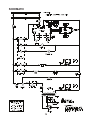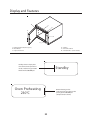
1
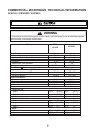
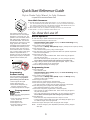
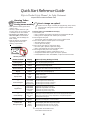
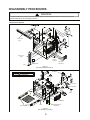
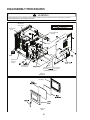
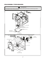
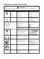
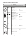
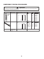
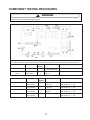
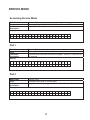
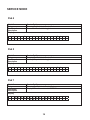
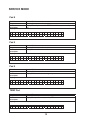
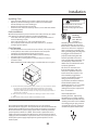
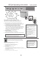
_______________________________________
Training Manual
R
AF
T
Combination Microwave/Convection Ovens
D
ACE5140 P1333203M
DS1400E P1333204M
UCA1400 P1333205M
50 Hz Combi
October, 2008
16400001
Table of Contents
Commercial Microwave Technical Information ............................................................. Page 2
Quick Start Reference Guide ......................................................................................... Page 3
Disassembly Procedures
Touch Panels/Displays/Triacs .................................................................................. Page 5
H.V.Board/I.S. Module ............................................................................................. Page 5
Back Panel .............................................................................................................. Page 6
Door ......................................................................................................................... Page 6
Stirrer Assembly ...................................................................................................... Page 7
Heater Assembly ..................................................................................................... Page 7
Component Testing Procedures................................................................................... Page 8-11
Power Test (Traditional) ......................................................................................... Page 12
Service Mode............................................................................................................ Page 13-15
Test Modes
Convection Temperature Test ................................................................................ Page 16
Convection Temperature Calibration ..................................................................... Page 16
Calibration ............................................................................................................. Page 16
Display Diagnostics ....................................................................................................... Page 17
Wiring Diagram .............................................................................................................. Page 18
Schematic ...................................................................................................................... Page 19
Owners Manual .................................................................................................... Page 20
User Maintenance.................................................................................................... Page 31
Care and Cleaning .................................................................................................... Page 32
Before Calling for Service .................................................................................................... Page 33
Warranty
1 year - Parts, Labor, Travel
3 years - Magnetron (Part Only)
1
Commercial Microwave Technical Information
ACE5140 / DS1400E / UCA1400
All safety information must be followed as provided in Service Manual.
!
WARNING
To avoid the risk of electrical shock, personal injury or death; disconnect power to oven and discharge capacitor
before servicing, unless testing requires power.
Models
ACE5410
DS1400E
Power Source
Voltage AC
Amperage (Single Unit)
Frequency
Single Phase, 3 wire grounded
Plug
Power Output − Microwave
Nominal microwave energy (IEC705)
Minimum temperature rise (∆T)
Operating Frequency
Power Consumption
Microwave only
Convection only
Combination
Dimensions
Cabinet (in / cm)
Width
Height
Depth
Oven Interior (in / cm)
Width
Height
Depth
Weight
Crated
Uncrated
UCA1400
230 VAC
16 A
50 Hz
X
CEE 7/7 Schuko
230 VAC
16 A
50 Hz
X
BS1363A
1400 Watts
10ºF / 5ºC
2450 MHz
1400 Watts
10ºF / 5ºC
2450 MHz
1400 Watts
2700 Watts
3400 Watts
1400 Watts
2700 Watts
3400 Watts
49 cm
46 cm
67 cm
(19 1/4")
(18 1/4")
(26 1/4")
49 cm
46 cm
67 cm
(19 1/4")
(18 1/4")
(26 1/4")
33 cm
27 cm
38 cm
(13")
(10 1/2")
(15")
33 cm
27 cm
38 cm
(13")
(10 1/2")
(15")
46 kg.
43 kg.
(102 lbs.)
(95 lbs.)
46 kg.
43 kg.
(102 lbs.)
(95 lbs.)
2
Quick Start Reference Guide
Refer to Product Safety Manual for Safety Statements
Complete Owner’s Manual available online
Oven Wall Clearances
A
B
C
A—For North American (UL/CSA) models, allow at least 2” (5.1 cm) of clearance around top of
oven. For International (50 Hz) models, allow at least 7” (17.8 cm) of clearance around top of
oven. Proper air flow around oven cools electrical components. With restricted air flow, oven
may not operate properly and life of electrical parts is reduced.
B—Allow at least 2 9/16” (6,5 cm) between air discharge on back of oven and back wall.
C—Allow at least 1 1/4” (3 cm) of clearance around sides of oven.
The switching operation of this
microwave oven can cause voltage
fluctuations on the supply line. The
operation of this oven under unfavorable voltage supply conditions can
have adverse effects. This device is
intended for the connection to a power
supply system with a maximum
permissible system impedance Zmax
of 1.1 Ohm at the interface point of
the user’s supply. The user has to
ensure that this device is connected
only to a power supply system which
fulfills the requirement above. If
necessary, the user can ask the public
power supply company for the system
impedance at the interface point.
So...how do I use it?
Manual Operation
To cook food using a specific entered time and power level.
1. Press Preheat On/Off pad to start the oven.
• Oven Preheating 450°F (230°C ) displays withOven Preheating flashing.
(example of 450°F (230°C) shown
2. Oven reaches preheat temperature.
• Signal sounds and Ready 450°F(230°C) displays. (example of 450°F (230°C) shown)
3. Press Time Entry pad.
• Enter desired cooking time by using numeric keypad.
4. Press Temp Entry pad if cooking temperature differs from preheat temperature.
• Enter the new temperature.
5. Press Power Level pad.
• Press numeric key pad for desired level. Press numeric key pad again to
set power level to 100%.
• For a lower microwave power, press pads 1 (for 10%) through 9 (for 90%).
0 turns off the microwave power and cooking is by convection only.
6. If stage cooking is desired, press STAGE pad and repeat steps 3, 4, and 5.
• Up to 4 different stages can be programmed.
7. Press the Start pad to begin the cooking cycle.
Programming Items
No popcorn
Programming
Preheat Setting
The factory default preheat setting
is 450°F (230°C). To program the
preheat setting oven must be ON:
1. Press Program Save pad.
2. Press Temp Entry pad.
3. Enter desired temperature by
using the numeric key pads.
4. Preheat temperature is changed.
Preprogrammed
Pads
To cook food using preprogrammed
cooking sequences.
1. Open oven door and place food
in oven. Close door.
2. Press desired pad.
3. Oven begins to cook.
4. At end of cooking cycle oven
beeps and shuts off.
1. Oven must be ON.
• Press Preheat On/Off.
• Oven Preheating 450°F (230°C) displays with Oven Preheating flashing.
(example of 450°F (230°C)
2. Oven reaches preheat temperature.
• Signal sounds and Ready 450°F (230°C) displays with Ready flashing.
(example of 450°F (230°C) shown)
3. Press Program Save pad.
4. Press pad to be programmed or reprogrammed.
5. Press Time Entry pad to program amount of cooking time.
• The total microwave cooking time (all stages combined) is 20 minutes.
6. Press Temp Entry pad to program the cooking temperature.
• Enter desired temperature by using numeric pads.
7. Press Power Level pad to program level of microwave power.
• Press numeric key pad for desired level. Press numeric key pad again to
set power level to 100%.
• For a lower microwave power, press pads 1 (for 10%) through 9 (for 90%).
0 turns off the microwave power and cooking is by convection only.
8. Press Stage pad.
• Enter cook time, temp and power level as in steps 4. 5 and 6.
• To enter another cooking stage for that pad, press Stage pad again. Up to
four different stages can be programmed.
9. Press the Program Save pad to save the program and changes.
NOTE: To discard changes, press Stop/Reset pad before pressing Program
Save pad.
3
Quick Start Reference Guide
Refer to Product Safety Manual for Safety Statements
Complete Owner’s Manual available online
Cleaning Teflon
Coated Oven
Cavity (some models)
• Wear protective rubber gloves when
cleaning oven.
• Use only a plastic utensil or nylon
scouring pad to aid in removing soil
or build-up from the oven interior.
• Do not use knife, metal utensil, or
steel wool pad to remove baked
on material. This will damage the
teflon coating.
• Refer to warranty for limitations
regarding teflon interior and
cleaning requirements.
?
Can I change an option?
Options such as single or double pad programming, beep volume,
and maximum cooking time can be changed to suit individual
preferences.
To change options oven STANDBY must display:
1. Press hidden pad.
• Pad is unmarked and located to the direct left of Preheat On/Off pad.
• Nothing will be displayed when hidden pad is pressed.
2. Press Program Save pad.
• The first user option will display. Oven is now in options mode.
3. Press number pad that controls option to be changed.
• See table below for options.
• Current option will display.
4. Press numeric pad again to change the option.
• Each time pad is pressed, option will change.
• Match code displayed with code for desired option.
5. Press Program Save pad to save changes.
• To change additional options, repeat steps 3 and 4.
• Changes take affect after Program Save pad is pressed.
• Press Stop/Reset to return to STANDBY, or open and close oven door.
DO NOT power spray
Numbered Pads
Display
1
Double Digit Entry
2
Manual Time Entry
3
Reset on Door Open
4
Keybeep
Disabled
Enabled
Disabled
Enabled
Disabled
Enabled
Disabled
Enabled
OFF
LOW
MEDIUM
HIGH
Solid Beep
3 Second Beep
4 Beeps Once
4 Beeps Repeating
15 SECONDS
30 SECONDS
60 SECONDS
120 SECONDS
ALWAYS
Disabled
Program Temp
Cavity Temp
Both
Degrees F
Degrees C
Disabled
Weekly
Monthly
Quarterly
5
Keybeep Volume
6
End of Cook Signal
7
Keypad Active
8
Preheat Warnings
TEMP PAD
Temperature Scale
CLEAN FILTER
Message Frequency
Options (Factory Settings in Bold)
Allows 10 (0-9) preprogrammed pads.
Allows 100 (00-99) preprogrammed pads.
Manual time entry/cooking not allowed
Manual time entry/cooking allowed
Opening oven door does not reset oven back to ready mode
Opening oven door resets the oven back to ready mode
Keys do not beep when pressed (keybeep off)
Keys beep when pressed (keybeep on)
Keybeep volume OFF
Keybeep volume LOW
Keybeep volume MEDIUM
Keybeep volume HIGH
Food done signal is a continuous beep until reset by user
Food done signal is a three second beep
Food done signal is four beeps, continuously.
Food done signal is four beeps, four times
Keypad time entry window is 15 seconds
Keypad time entry window is 30 seconds
Keypad time entry window is one minute
Keypad time entry window is two minutes
Keypad time entry window is always active
Both temperature warnings off
Warning only when preheat temperature does not match preprogrammed temperature
Warning only when actual oven cavity temperature is not to preheat temperature
Both temperature warnings on
Temperatures are displayed in °F for 60 Hz models
Temperatures are displayed in °C for 50 Hz models
Oven will not display Clean Filter
Oven will display Clean Filter every seven (7) days
Oven will display Clean Filter every thirty (30) days
Oven will display Clean Filter every ninety (90) days
For full product documentation visit:
www.amanacommercial.com
4
Disassembly procedures
!
WARNING
To avoid risk of electrical shock, personal injury or death; disconnect power to oven and discharge capacitors
before following any disassembly procedures.
Component Location
Touch Panel
(Top)
Touch Panel
(Side)
Plug
Triac #2
Heating
Element
Triac #3
Microwave
Data Key Board
Figure 1
Touch Panels/Displays/Triacs
Fan Blade
High Voltage Components
Magnetron
Line Filter
Fuse Block
Capacitor
Fuse
H.V. Board
Rack Support
Filter
Interlock Switch
Assembly
Figure 2
H.V. Board/I.S. Assembly
5
Disassembly procedures
!
WARNING
To avoid risk of electrical shock, personal injury or death; disconnect power to oven and discharge capacitors
before following any disassembly procedures.
Magnetron
Inlet Cover
High Voltage Components
Waveguide
Duct
Control Thermal
Cutouts
Heater Box
Capacitors
Relay
Magnetron
Thermal
Cutout
Diode
High Voltage
Transformer
Fold diagram and place against
blower br
nge prior to
assembling access panel.
Figure 3
Back Panel
Inner Door
Assembly
Figure 4
Door
6
Disassembly procedures
!
WARNING
To avoid risk of electrical shock, personal injury or death; disconnect power to oven and discharge capacitors
before following any disassembly procedures.
Stirrer Shaft
Stirrer Blade
Stirrer Insert
Stirrer Cover
Stirrer Cover
Mounting Clip
Figure 5
Stirrer Assembly
NOTE:
Thermal Cutouts
Torque
to .56 Newton-Meters
Convection
Fan Blade Rear
Convection
Fan Blade Front
Convection
Motor
Single Heating Element
Fan Blade
Heater Box
Torque to .56 Newton-Meters
Left Handed Nut
Figure 6
Heater Assembly
7
Component Testing Procedures
!
WARNING
To avoid risk of electrical shock, personal injury or death; disconnect power to oven and discharge capacitors
before following any disassembly procedures.
Illustration
Component
Thermal cutout
31866P01 ...............
Test
Disconnect all wires from TCO.
Measure resistance across terminals.
Oven TCO . ............................................
B5684123 ..............
Fan TCO . ............................................
B5684121...............
Diode
Magnetron TCO........................................
Reverse leads for second test.
MT1
Disconnect wires to triac.
Measure resistance from:
MT1 to MT2 ..............................................
MT1 to Gate..............................................
MT2
GA TE
Triac 1 (top) is for motors
Triac 2 (middle) is for heater element
Triac 3 (bottom) is for microwave
Capacitors – 0.65 µf
MT2 to Gate..............................................
All terminals to ground..............................
Voltage check measure voltage from:
MT1 to Gate..............................................
Discharge Capacitor
Remove wires from capacitor terminals and
connect ohmmeter, set on highest
resistance scale to terminals.
Snubber assembly
Open at 300 °F (149 °C) and closed at
257 °F (125 °C)
Open at 350 °F (177°C) and closed at
17 °F (-8°C)
Open at 280 °F (137°C) and closed at
180 °F (82°C)
Discharge Capacitor
Remove diode lead from capacitor and
connect ohmmeter.
Triac
Results
in one direction and 50KΩ or more in
the opposite direction.
NOTE: Ohmmeter must contain a
battery of 6 volts minimum.
Caution - Do not operate oven with
wire to terminal MT2 removed.
Approximately 60 Ω
0.8 VAC when energized. If no
voltage, check H.V. board and wiring.
Between Terminals: Meter should
momentarily
return to over 5 M Ω
occurs, replace capacitor.
Also check between each terminal and
capacitor case.
Disconnect wires to snubber.
Measure resistance across terminals ..........
Magnetron
Discharge Capacitor
Between Terminals: Less than 1 Ω
Remove wires from magnetron and
connect ohmmeter to terminals. Also check
between each terminal and ground.
Each terminal to ground measures
Microwave blower
motor
Remove all wires from motor.
Power relay
Coil voltage – unit running
Terminal 0 to 1..........................................
Coil resistance
Terminal 0 to 1..........................................
Measure resistance across coil.
8
Note: This test is not conclusive. If
oven does not heat and all other
components test good replace the
magnetron and retest.
Approximately 30 Ω
(line voltage)
21 K Ω
Component Testing Procedures
!
WARNING
To avoid risk of electrical shock, personal injury or death; disconnect power to oven and discharge capacitors
before following any disassembly procedures.
Illustration
Component
Transformer
6
5
Measure resistance from:
230 to COM ..............................................
230 to Ground..............................................
Terminal 5 to 6.............................................
Terminal 4 to Ground...................................
4
COM
230
Interlock switch
Door Closed
4
3 Secondary
5 Primary
7
8 Monitor
2
7
8
4
3
5
Convection blower
motor
With door open measure resistance from:
Terminal 2 to 3............................................
Terminal 4 to 5............................................
Terminal 7 to 8............................................
Resistance thermal
device (RTD)
Line filter
Brown
Less than 1 Ω
Approximately 60 - 70 Ω
Indicates continuity
Indicates continuity
Indicates continuity
Remove wires from motor.
Measure resistance across
terminals A and B ........................................
Approximately 20 Ω
Disconnect wires from terminals.
Measure resistance across heating
element.
Element
IN
Less than 1 Ω
B
Heating element
assembly
Blue
Results
Disconnect wires to switch.
With door closed measure resistance from:
Terminal 2 to 3............................................
Terminal 4 to 5............................................
Terminal 7 to 8............................................
2
A
Test
Discharge Capacitor
Remove all wires from terminals.
Blue
OUT
Brown
2700 W .......................
Approximately 15 Ω
Temperature
Resistance
0°C (32 °F) ....................................................
24°C (75 °F) ..................................................
177 °C (350 °F) ..............................................
1000 Ω
1091 Ω
1654 Ω
Disconnect wire from terminals.
Measure resistance of the following
terminals:
Blue to Blue ......................................
<1 Ω
Brown to Brown ................................
<1 Ω
9
Component Testing Procedures
!
WARNING
To avoid risk of electrical shock, personal injury or death; disconnect power to oven and discharge capacitor
before servicing, unless testing requires power.
Illustration
Test
Continuity is indicated as 100 Ω and
below.
Top touch panel
Continuity is indicated as 100 Ω and
below.
High voltage board
to display module
harness
Test continuity of wires.
1
Component
Side touch panel
Pad
1
2
3
4
5
6
7
8
9
0
Start
Stop/Reset
Pad
Preheat
Time Entry
Temp Entry
Power Level
Stage
Program Save
Hidden Pad
Results
Trace
3&5
3&6
3&7
3&8
3&9
4&5
4&6
4&7
4&8
4&9
5&6
6&9
Trace
3&4
5&7
7&8
5&8
5&9
6&7
8&9
1
Wire harness
10
Indicates continuity
Measurement
Continuity
Continuity
Continuity
Continuity
Continuity
Continuity
Continuity
Continuity
Continuity
Continuity
Continuity
Continuity
Measurement
Continuity
Continuity
Continuity
Continuity
Continuity
Continuity
Continuity
Component Testing Procedures
!
WARNING
To avoid risk of electrical shock, personal injury or death; disconnect power to oven and discharge capacitor
before servicing, unless testing requires power.
H.V. board
In straight convection mode, both elements operate simultaneously.
In combination mode, the rear element will operate simultaneously with either the microwave or front element.
Function
Test Set-Up
Meter
Probe Placement
Results
Setting
Input to H.V. board
At H.V. board
Volts
J1 pin 1 (Black wire)
Line voltage
& J1 pin 2 (Red wire)
Output to display
Disconnect
Volts
J5 pin 1 &
7.4 VDC
board
J5 connector
J5 pin 47
Function
Cooling fan
Convection motor
Microwave
Heater
Test Set-Up
Disconnect
J2 connector
Disconnect
J2 connector
Disconnect
J4 connector
Disconnect
J4 connector
Meter
Setting
Ohms
Ohms
Ohms
Ohms
Probe Placement
J1 pin 1 (Black wire)
& J2 pin 4
J1 pin 1 (Black wire)
& J2 pin 3
J4 pin 4 &
J4 pin 5
E6 & J4 pin 1
11
Results
Test mode 5 off – no continuity
Test mode 5 on – < 1 Ω
Test mode 4 off – no continuity
Test mode 4 on – < 1 Ω
Test mode 3 off – no continuity
Test mode 3 on – < 1 Ω
Test mode 1 off – no continuity
Test mode 1 on – < 1 Ω
Power Test
!
WARNING
To avoid risk of electrical shock, personal injury or death; disconnect power to oven and discharge capacitor
before servicing, unless testing requires power.
Power Test
All Amana and Menumaster microwave oven power outputs are rated using the IEC705 standards. Using the
IEC705 test method requires precision measurements and equipment that is not practical to be performed in the
field. Using the test shown below will indicate if the oven performance is satisfactory.
Test equipment required:
•
•
1000 ml test container (Part # 12018801) and thermometer.
Digital watch / watch with a second hand for use on ovens with electromechanical timers.
Important Notes:
•
•
•
Low line voltage will cause low temperature rise / power output.
Ovens must be on a dedicated circuit, properly grounded, and polarized. Other equipment on the same
circuit may cause a low temperature rise / power output.
This test and results are not a true IEC705 test procedure and are only intended to provide servicers with an
easy means of determining if the microwave oven cooking output is correct.
Procedure
1. Fill the test container to the 1000 ml line with cool tap water.
NOTE:
Water temperature should be approximately 60° F / 16° C.
2. Using the thermometer, stir water for five to ten seconds; measure, and record the temperature (T1).
3. Place test container of water in the center of oven cavity and close door.
4. Heat the water for a 33-second full power cycle.
NOTE:
Use a digital watch or a watch with a second hand for ovens with electromechanical timers.
5. At end of the cycle, remove test container. Using the thermometer, stir water for five to ten seconds and record
temperature (T2).
6. Subtract the starting water temperature (T1), from the ending water temperature (T2) to obtain the temperature
rise (∆T).
7. If the temperature rise (∆T) meets or exceeds the minimum, the test is complete. If the temperature rise (∆T)
fails to meet the minimum temperature rise, test the line voltage to verify it is correct. Then repeat steps 1-6
making sure to change the water. If the temperature rise (∆T) fails to meet the minimum temperature rise again
the oven will require service.
Minimum Temperature Rise at Thirty -Three (33) Seconds Run Time
∆T
(°F)
Cooking
Power Output
∆T
(°C)
14° F ............. 1400
Cooking
Power Output
7.5°C ........ 1400
12
service mode
Accessing Service Mode
Service Mode
Pressing Hidden Pad, 1, 3, 5, 7, 9 while in Preheat is OFF
Main Service Mode Menu
Mode Name
Entry
Functional
Description
Display
S
5
6
e
0
r
v
H
i
Z
c
e
2
M o
3 0
d
e
V
Pad 1
Service Pad 1
Pressing Pad 1 while in Service Mode
Calrod #1 and convection fan shall be toggled. When on, it shall run for
62 seconds.
Mode Name
Entry
Functional
Description
Display
C
a
l
r
o
d
A
:
m p
s
:
O
1
N
2
Pad 3
Service Pad 3
Pressing Pad 3 while in Service Mode
Magnetron #1 shall be toggled. When on, it shall run for 62 seconds.
Mode Name
Entry
Functional
Description
Display
M a
0 0
g
:
n
4
e
5
t
r
o
n
A
#
m p
13
1
s
:
:
O
1
N
2
service mode
Pad 4
Service Pad 4
Pressing Pad 4 while in Service Mode
Convection Fan shall be toggled.
Mode Name
Entry
Functional
Description
Display
C
o
n
v
.
A
F a
m p
n
s
:
:
O
0
N
3
O
N
Pad 5
Service Pad 5
Pressing Pad 5 while in Service Mode
Auxiliary Output shall be toggled.
Mode Name
Entry
Functional
Description
Display
A
u
x
.
O
u
t
p
u
t
:
Pad 7
Service Pad 7
Pressing Pad 7 while in Service Mode
Displays Tube Hours stored in EEPROM
Mode Name
Entry
Functional
Description
Display
M a
g
n
e
t
0
r
0
o
1
n
7
4
14
H
3
o
u
r
S
service mode
Pad 8
Service Pad 8
Pressing Pad 8 while in Service Mode
Displays Door Cycles stored in EEPROM. Will always be a multiple of
ten.
Mode Name
Entry
Functional
Description
Display
D
o
o
0
r
0
2
C
4
y
5
c
3
l
8
e
0
s
Pad 9
Service Pad 9
Pressing Pad 9 while in Service Mode
Prompts user to clear service information.
Mode Name
Entry
Functional
Description
Display
P
C
r
l
e
e
s
a
s
r
S
s
T
e
A
r
R
v
T
.
t
i
o
n
f
Pad 0
Service Pad 0
Pressing Pad 0 while in Service Mode
Displays offset used when heating cavity.
Mode Name
Entry
Functional
Description
Display
T
e
m p
.
2
0
O
°
f
C
f
s
e
T
TEMP Pad
Display Temperature
Pressing the Temp Pad in Service Mode.
Displays temperature as reported by RTD
Mode Name
Entry
Functional
Description
Display
C
a
v
i
1
t
9
y
4
°
T
C
e
m P
15
o
Test modes
!
WARNING
To avoid risk of electrical shock, personal injury or death; disconnect power to oven and discharge capacitors
before following any disassembly procedures.
Convection Temperature Test
Convection Temperature Calibration
NOTE: It is absolutely necessary to own and use a
thermocouple type oven tester to accurately
measure oven temperatur e. No other type of
thermometer can take its place.
NOTE: It is normal for the average oven temperature
to vary from the oven setting by as much as
C
mind.
NOTE: Before testing an oven to check calibration,
inspect the RTD for proper mounting.
Calibration
1. Place one wire rack in center position. Remove
any other racks and utensils.
2. Clip thermocouple to the center rack and run lead
outside oven door, or wrap thermocouple around
rack and have the tip of thermocouple extend
upward towards top of cavity approximately 1".
3. Press PREHEAT ON/OFF pad.
4. Press PROGRAM SAVE pad.
5. Press TEMP pad.
6. Enter 230°C.
7. Allow oven to cycle one time.
8. Record high and low peaks from next two cycles.
NOTE: Door must be closed and unit must be in
STANDBY mode.
1. Press HIDDEN PAD.
2. Press pads 1,3,5,7, 9.
3. Press "0" pad.
ITEM
STG QTY
C M
LMT
1
2
3
4
1
Cycle
2
879°F
NOTE:
921°F
= 1800°F
NOTE:
Cycle
2
230°C
460°C
NOTE:
HIGH
240°C
LOW
230°C
240°C
+
and advances in 1 and 2° increments.
5. Press STOP/RESET
Celsius Example:
1
COOK
LEVEL
Celsius
1800°F / 4 = 450°F average temperature
Cycle
STANDBY
and advances in 2 and 3° increments.
461°F
+
READY
Fahrenheit
HIGH
460°F
439°F
NOT
4. Press the "0"
Fahrenheit Example:
Cycle
PREHEAT
NOTE:
NOTE: Display does not indicate if heating elements
LOW
440°F
POWER
made.
Fahrenheit Example:
• Oven temperature is set for 450°F
• Average of temperature test is 475°F
•
•
is shown in the display (10 – 25 = –15)
480°C = 940°C
940°C / 4 = 235°C average temperature
If the average temperature is too high or too low the
Celsius Example:
• Oven temperature is set for 230°C
• Average of temperature test is 240°C
•
•
shown in the display (5– 10= –5)
16
DISPLAY DIAGNOSTICS
Error Codes: During operation, the display may show the following service codes:
Note: Before scheduling service for any error codes, instruct customer to
unplug oven for 1 minute, reconnect power, and re-test. If unit operates
properly, no service call is required.
DESCRIPTION
CORRECTIVE ACTION
Error 1U
Chassis Memory Not Found
Error 1F
Error 2
Chassis Memory Not
Programmed
Failed H.V. Board
Error 3
Failed H.V. Board
Error 4
Failed H.V. Board
Error 5
Shorted Touch Panel
Error 6
Error 7-O
Error 7-S
Door Open
Options Scrambled
Open RTD
Shorted RTD
Door Interlock Primary
Switch
Error
Oven to Hot
Control TCO Open
-Check EZ Card Harness
-Replace EZ Card Board
-Unplug Oven and Re-Plug In
-Replace H.V. Board
-Replace H.V. Board
-Replace Touch Panel
-Replace H.V. Board
-Replace Touch Panel
-Replace H.V. Board
-Incorrect H.V. Board Installed in Oven
Note: If touch panel is pressed for more than 30
seconds, this error code will appear.
-Disconnect Oven From Power Supply
-Disconnect Side Touch Panel Connector
From Display Board.
-Reconnect Oven to Power Supply
-If “Err5” Reappears After 30 Seconds,
Replace Top Touch Panel.
-If “Err5” Does Not Reappear After 30
Seconds, Replace Side Touch Panel.
Replace H.V. Board
Check RTD and Wiring to H.V. Board
Check RTD and Wiring to H.V. Board
-Verify Latch Mechanism Moves Freely On
Door.
-Verify J1 Connector On Display Board Is
Properly Seated.
-Test Interlock Switch Assembly and Perform
Door Adjustment If Necessary.
-Replace Interlock Switch Assembly.
-Check Fan Blade.
DISPLAY
-Check Airflow.
-Fan Motor not Operating.
17
2
BK-8
BK-8
6
8
1
F
15A
XFMR
FUSE
5
4
8
7
BK-9
3
2
WH-17
WH-14
BU-16
FA
MAGNETRON
MAG TCO
INTERLOCK
SWITCH
PK-38
GN-37
RD-15
RD-23
4
BK-24
BK-18
0
BK-18
YL-28
BK-37
RD-15
BU-16
WH-17
COM
230
5
4
HV
WH-14
POWER
TRANSFORMER
6
RD-19
RD-20
2
G
RECTIFIER
BK-36
YL-28
BU-35
VT-29
CAPACITOR
CAPACITOR
MAGNETRON
TRIAC (TR3)
(BOTTOM)
1
2
G
HEATER
TRIAC (TR2)
(TOP)
1
VT-32
YL-31
POWER
RELAY
BK-37
RD-13
CONVECTION
MOTOR
GY-3
GN-37
VT-29
VT-7
LOWER
SWITCH
J5
HEATER
J1
DISPLAY
BOARD
J4
UPPER
SWITCH
J6
J2
RD-12
BLOWER
MOTOR
GN/YL
YL-6
PK-38
BR
BU
LINE
FILTER
BR
BU
BR
BU
BR
BU
A
B
C
D
WH
TERMINAL
BLOCK
E6
E7
J7
J10
J6
J11
POWER
CORD
OVEN
TCO
BR
RD
J8
VT-7
BK-22
GN/YL
BK-4
VT-32
BU-35
YL-31
BK-36
BK
GN
WH
RD
GN
LIMITER
BU
BK-4
RD-1
BR
BU
GN
BK
15A
LINE FUSE
SHIELDED
CABLE
BR
BR
RD-5
J4
POWER
BOARD
J5
RD-20
J3
E3
E1
E5
E4
J2
J1
E2
RD23
GY-3
YL-6
RD-12
COLOR CODE
RED RD
PINK PK
ORANGE OR
YELLOW YL
GREEN GN
BLUE BU
VIOLET VT
BLACK BK
BROWN BR
GRAY GY
WHITE WH
RD-5
OR-25
BR-2
RD-19
BK-26
BK-26
BK-22
RD-13
BK-9
WIRE CODE
HIGH VOLTAGE
LOW VOLTAGE
BK-24
18
BR-2
RTD
OR-25
WIRING DIAGRAM
PART NO. 13070304
Wiring diagram
schematic
L1
GND
230V 50HZ
L2
SCHEMATIC CONDITION: DOOR OPEN
LINE FILTER
GND
SHIELDED
CABLE
OVEN
TCO
P2
20A
FUSE
UPPER
KEYBOARD
DATA KEY
BOARD
E2/E3
E1
P1
J6
J4
CURRENT SENSE
J8-1
J5
POWER BOARD
J6
J8-2
J5
J8-3
J8-4
4
INTERLOCK
(PRIMARY)
5
J1-1
J8-7
J8-6
LOWER
KEYBOARD
SHIELDED
CABLE
J1-1
J1-3
DISPLAY
BOARD
J1-2
T
RTD
K1
LIMITER
J2-4
M1
COOLING FAN
K2
J2-3
M2
CONVECTION FAN
K3
J7-5
K9
E6/E7
TRIAC (2)
HEATER
(TOP)
J4-1
J7-4
T2
G
POWER
BOARD
T1
HEATER
K4
E4/E5
J3-3
0
POWER BOARD
P OWE R
R E L AY
2
1
3
6
INTERLOCK
(SECONDARY)
POWER
RELAY
8
7
8
INTERLOCK
(MONITOR)
J4-4
4
K7
J4-5
2
POWER
RELAY
J7-3
J7-2
POWER BOARD
MAGNETRON
TCO
15A
FUSE
TRIAC (3)
MAGNETRON
(BOTTOM)
POWER
TRANSFORMER
230
T2
G
POWER
BOARD
T1
COM
6
5
CAP
CAP
CAP
RES
INTERLOCK SWITCH SCHEMATIC
DOOR CLOSED
DANGER
HIGH VOLTAGE
RECTIFIER
2
3 SECONDARY
4
5 PRIMARY
7
8 MONITOR
CAUTION:
FA
F
MAGNETRON
19
DO NOT REMOVE WIRE FROM
TRIAC TERMINAL T2 DURING
TESTING. THIS WILL CAUSE
HV BOARD TO SHORT OUT
Owner's Manual
Contents
Model Identifi cation ................................... 21
Grounding Instructions ............................... 22
Installation ................................................. 22
Display and Features ................................. 23
Programming ............................................. 26
Convection Cooking ................................... 27
Combination Cooking
(microwave and convection) .................... 28
User Options ............................................ 29
EZCard Operating Instructions ................. 30
User Maintenance .................................... 31
Service Codes .......................................... 31
Care and Cleaning .................................... 32
Before Calling Service .............................. 33
Commercial Combination Oven
(Microwave and Convection)
Keep these instructions for future
reference. If the equipment changes
ownership, be sure this manual
accompanies equipment.
20
Model Identification
When contacting Amana, provide product information.
Product information is located on oven serial plate.
Record the following information:
Model Nu mber: ____________________________
Serial or S/N Number: _______________________
Date of installation: _________________________
Dealer’s name and address: __________________
________________________________________
________________________________________
Any questions or to locate an authorized Amana servicer,
call Amana ComServ Service Support.
– Inside the U.S.A. or Canada, call toll-free at 866-4262621.
– Outside the U.S.A. and Canada, call 319-368-8120.
– Email: [email protected].
Warranty service must be performed by an authorized
Amana servicer. Amana also recommends contacting an
authorized Amana servicer, or Amana ComServ Service
Support if service is required after warranty expires.
21
Installation
Unpacking Oven
•
•
•
•
Inspect oven for damage such as dents in door or inside oven cavity.
Report any dents or breakage to source of purchase immediately.
Do not attempt to use oven if damaged.
Remove all materials from oven interior.
If oven has been stored in extremely cold area, wait a few hours before
connecting power.
! WARNING
To avoid risk of electrical shock
or death, this oven must be
grounded and plug must not be
altered.
Radio Interference
Microwave operation may cause interference to radio, television, or a similar
oven. Reduce or eliminate interference by doing the following:
• Clean door and sealing surfaces of oven according to instructions in
Care and Cleaning section.
• Place radio, television, etc. as far as possible from oven.
• Use a properly installed antenna on radio, television, etc. to obtain
stronger signal reception.
Oven Placement
•
•
•
•
•
Do not install oven next to or above source of heat, such as pizza oven
or deep fat fryer. This could cause microwave oven to operate
improperly and could shorten life of electrical parts.
Do not block or obstruct oven filter. Allow access for cleaning.
Install oven on level countertop surface.
If provided, place warning label in a conspicuous place close to
microwave oven.
Outlet should be located so that plug is accessible when oven is in place.
A
B
C
A—For North American (UL/CSA) models, allow at least 2” (5.1 cm) of clearance around
top of oven. For International (50 Hz) models, allow at least 7” (17,8 cm) of
clearance around top of oven. Proper air flow around oven cools electrical
components. With restricted air flow, oven may not operate properly and life of
electrical parts is reduced.
B—Allow at least 2 9/16” (6,5 cm) between air discharge on back of oven and back
wall.
C—Allow at least 1 1/4” (3 cm) of clearance around sides of oven.
Oven Clearances
The switching operation of this microwave oven can cause voltage
fluctuations on the supply line. The operation of this oven under unfavorable
voltage supply conditions can have adverse effects. This device is intended
for the connection to a power supply system with a maximum permissible
system impedance Zmax of 1.1 Ohm at the interface point of the user’s
supply. The user has to ensure that this device is connected only to a power
supply system which fulfills the requirement above. If necessary, the user can
ask the public power supply company for the system impedance at the
interface point.
22
Earthing
Instructions
Oven MUST be
grounded.
Grounding reduces risk of electric
shock by providing an escape wire
for the electric current if an electrical
short occurs. This oven is equipped
with a cord having a grounding wire
with a grounding plug. The plug must
be plugged into an outlet that is
properly installed and grounded.
Consult a qualified electrician or
servicer if grounding instructions are
not completely understood, or if
doubt exists as to whether the oven
is properly grounded.
Do not use an extension cord.
If the product power cord is too
short, have a qualified electrician
install a three-slot receptacle. This
oven should be plugged into a
separate circuit with the electrical
rating as provided in product
specifications (available on Amana’s
wavelink website). When the
combination oven is on a circuit with
other equipment, an increase in
cooking times may be required and
fuses can be blown.
External Equipotential
Earthing Terminal (export only)
Equipment has secondary earthing
terminal. Terminal provides external
earthing connection used in addition
to earthing prong on plug. Located
on outside of oven back, terminal is
marked with symbol shown below.
Display and Features
B
C
D
A
E
G
A—Oven Door Handle (Lift to open.)
B—Rack Guides
C—Top Control Panel
D—Display
E—Side Control Panel
G—Air Intake Filter (some models)
Oven Features
Standby shows in display after
oven door has been opened and
closed, or after turning oven OFF
with the Preheat On/Off pad.
Standby
Oven Preheating
230°C
Oven Preheating and set
temperature shows in display after
pressing Preheat On/Off pad.
(example of 230°C shown)
23
Display and Features
Ready and set temperature
displays after pressing Preheat
On/Off pad. Ready indicates
the oven is up to temperature.
(example of 230°C shown)
(cont’d)
Ready
230°C
Indicates oven is in a
preprogrammed cooking program
Item-05
Stage:1
01:23 230°C MW:50%
Time left in
cooking
program
Cooking
temperature
Cooking information shows in
display after pressing a single (or
double) digit pad while in Ready
Mode.
Percentage of
microwave
power
Indicates oven is in a
manual cooking program
Manual
Stage: 1
00:15 246°C MW:100%
Time left in
cooking
condition
24
Cooking
temperature
Indicates
percentage of
microwave
power
Display and Features
Start pad
The Start pad is
used to begin a
manual time entry cooking cycle.
Stop/Reset
pad
The Stop/Reset pad
stops a cooking sequence in
progress, clears out any remaining
time, and also ends a
programming or user option cycle.
When the Stop/Reset pad is used
to end a programming or option
change, the changes are
discarded.
Temperature warnings
The combination oven has two
distinct temperature warnings.
Warnings sound with a three beep
signal when a programmed pad is
pressed. Warnings are:
•
•
A warning when the preheat
temperature does not match the
preprogrammed temperature of
a cooking condition.
A warning when the actual
oven cavity temperature is not
to preheat temperature, such
as when the oven is first
started.
To override the warning and begin
a cooking cycle, press the Start
pad. To turn off warnings, see User
Options section.
(cont’d)
Cooking Display
DISPLAYS
DESCRIPTION
OVEN
PREHEATING
230°C
Oven Preheating 230°C displays when oven
turned on and is warming up to the selected
preheat temperature. Oven Preheating also
flashes when a cooking condition can be started
programmed. (example of 230°C shown)
READY 230°C
Ready 230°C displays when oven has reached
preheat temperature and is ready to cook. Read
also flashes when a cooking condition can be
started or programmed. (example of 230°C shown)
00:00
Displays cooking time. If stage cooking is
programmed, total cooking time is displayed.
MW 50%
MW 50% displays the current microwave power
level. 100% is the hi ghest setting , and 0% is low
(no microwave energy used). (example of 50% shown)
ITEM-05
ITEM-05 displays the single or double digit entry
of a pro grammed cooking condition when using a
programmed pad. (example of Item 05 shown)
STAGE 1
Stage 1 displays to show the stage number (1
through 4) the oven is at in the cooking condition
STANDBY
STANDBY displays when oven is turned off, and
also after the oven is plugged in, the door is
opened, and then shut.
Programming Display
DISPLAYS
DESCRIPTION
Enter Program
to Add/Review:
Displays when oven is in programming mode for
single pad or double pad memory.
STAGE 1
Displays stage number during cooking or when
programming a specific cooking stage. Stage
number (1 through 4) indicates the stage that is
being used.
25
Programming
Programming Pads
Oven is shipped from the factory for single pad programming. To change the
oven default to double pad programming, see User Option section. To
program the amount of time, power level, or temperature setting for a pad:
1. Oven must be ON.
• Press Preheat On/Off pad.
• Oven Preheating 230°C shows in display with
Oven Preheating flashing. (example of 230°C shown)
2. Oven reaches preheat temperature.
• Signal sounds and Ready 230°C shows in display with Ready
flashing. (example of 230°C shown)
2. Press Program Save pad.
• Programming mode begins.
• Enter Program to Add/Review: shows in display.
3. Press pad to be programmed or reprogrammed.
• Display will change to review all settings for the pad.
• The pad number that is being programmed displays beside the word
ITEM .
4. Press Time Entry pad to program amount of cooking time.
• Enter desired cooking time by using numeric key pads.
• The total microwave cooking time (all stages combined) is 20
minutes.
5. Press Temp Entry pad to program the cooking temperature.
• Enter desired convection temperature by using numeric
pads.
6. Press Power Level pad to program level of microwave
power.
• Press numeric key pad for desired level. Press numeric
key pad again to set power level to 100%.
• For a lower microwave power, press pads 1 (for 10%) through 9 (for
90%). 0 turns off the microwave power and cooking is by
convection only.
7. Press Program Save pad to save the program changes.
8. To discard changes, press Stop/Reset pad.
Programming Multiple Stages
Stage cooking allows consecutive cooking cycles without interruption.
Up to four different cooking cycles can be programmed into a memory pad.
To use stage cooking:
1. Follow steps 1 through 6 above.
7. Press Stage pad.
• This will begin programming for the next cooking stage.
• Display indicates stage to be programmed.
• Enter cook time, temp and power level as in steps 4. 5 and 6.
• To enter another cooking stage for that pad, press Stage pad
again.
• Up to four different stages can be programmed.
8. Press Program Save pad to save the program and
changes.
9. To discard changes, press Stop/Reset pad before pressing
Program Save pad.
26
Programming
Preheat Setting
The convection temperature setting
can be set between 150°F to 475°F
(65°C to 250°C). It is recommended
to set the preheat setting to the most
commonly used temperature for that
oven. The factory default preheat
setting is 450°F (230°C).
To program the preheat setting :
1. Press Program Save pad.
2. Press Temp Entry pad.
3. Enter desired temperature by
using the numeric key pads.
• Temperature must be entered
in 25°F (10°C) increments. If
not, the temperature will
automatically change to the
nearest 25°F (10°C).
4. Preheat temperature is changed.
What is stage
cooking?
Stage cooking enables
several different cooking cycles, or
stages, to be used consecutively
without repeated input from the user.
Stage cooking can be set to defrost
food initially, then cook it, and then
keep the food warm until serving time.
Convection Cooking
!
CAUTION
To avoid risk of burns, handle utensils, racks, and door with care. Allow oven, utensils, and racks
to cool before cleaning. Oven, utensils, and racks, become hot during operation.
To operate the oven for convection cooking only, you can use preprogrammed pads or manual time entry. The
following instructions are for convection cooking only. For combination cooking, see that section.
Convection Cooking with Programmed Pads
Convection
Cooking
Convection cooking utilizes both a
convection element and fan to
evenly distribute heated air
throughout the oven cavity. By
circulating air, no hot or cold spots
occur, creating a consistent
temperature envelope around the
food. These consistent
temperatures cook food evenly
and reduces cooking time. Oven
will always operate in convection
mode.
1. Press Preheat On/Off pad to start the oven.
• Oven begins a preheat cycle.
• Oven Preheating 230°C shows in display. (example of
230°C shown)
• To change preheat temperature, see Programming.
2. Oven reaches preheat temperature.
• Signal sounds and Ready 230°C displays.
3. Press selected pad.
• If using single pad programming, press pad and oven begins
automatically.
• For double pad programming, press pads in proper sequence and oven
begins automatically.
4. Cooking cycle begins
• Preprogrammed cooking program, total cooking time, cooking
temperature, percentage of microwave power, and stage are all displayed.
5. Oven finishes cooking sequence
• An end of cycle beep signals the end of the cooking cycle.
• Done shows in display.
• Oven interior and cooking dish will be hot.
6. Press Preheat On/Off pad to shut off oven.
Convection Cooking Using Manual Cooking
Operation
1. Press Preheat On/Off pad to start the oven.
• Oven begins a preheat cycle.
• Oven Preheating 230°C shows in display. (example of
230°C shown)
• To change preheat temperature, see Programming .
2. Oven reaches preheat temperature.
• Signal sounds and Ready 230°C displays.
3. Press Time Entry pad.
• Enter desired cooking time by using the numeric keypad.
4. Press Temp Entry pad if cooking temperature differs from preheat
temperature.
• Enter the new temperature.
5. Press Power Level pad.
• Press numeric key pad for desired level. Press numeric key
pad again to set power level to 100%.
• For a lower microwave power, press pads 1 (for 10%) through 9 (for 90%).
0 turns off the microwave power and cooking is by convection only.
6. If stage cooking is desired, press Stage pad and repeat steps 3,
4, and 5.
• Up to 4 different stages can be programmed.
7. Press the Start pad to begin the cooking cycle.
27
Combination Cooking
!
(microwave and convection)
CAUTION
To avoid risk of burns, handle utensils, racks, and door with care. Allow oven, utensils, and racks
to cool before cleaning. Oven, utensils, and racks, become hot during operation.
To operate the oven for combination cooking, you can use preprogrammed pads or manual time entry. The following
instructions are for combination cooking only. For convection only cooking, see that section.
Combination Cooking With Preprogrammed Pads
1. Press Preheat On/Off pad to start the oven.
• Oven begins a preheat cycle.
• Oven Preheating 230°C shows in display.
(example of 230°C shown)
• To change preheat temperature, see Programming.
2. Oven reaches preheat temperature.
• Signal sounds and Ready 230°C displays.
3. Press selected pad.
• If using single pad programming, press pad and oven begins automatically.
• For double pad programming, press pads in proper sequence and oven
begins automatically.
4. Cooking cycle begins
• Preprogrammed cooking program, total cooking time, cooking temperature,
percentage of microwave power, and stage are all displayed.
5. Oven finishes cooking sequence
• An end of cycle beep signals the end of the cooking cycle.
• Done shows in display.
• Oven interior and cooking dish will be hot.
6. Press Preheat On/Off pad to shut off oven.
Combination
Cooking
The combination mode uses
both the speed of microwave
energy and browning of
convection cooking to yield
fast, high quality food.
•
Microwave cooking uses
high frequency energy
waves to heat the food.
When cooking, microwave
energy causes food
molecules to move rapidly.
This rapid movement
between the food
molecules creates heat,
which cooks the food.
POWER displays when
oven is generating
microwave energy for the
current cycle.
•
Convection cooking uses
the selected oven
temperature to bake and
brown foods. The
circulating air surrounds
food in an envelope of
evenly heated air.
•
Oven will maintain a
minimum convection
temperature of 65°C
(150°F) to ensure drier air
and more even cooking.
Combination Cooking Using Manual Cooking
Operation
1. Press Preheat On/Off pad to start the oven.
• Oven begins a preheat cycle.
• Oven Preheating 230°C shows in display.
(example of 230°C shown)
• To change preheat temperature, see Programming .
2. Oven reaches preheat temperature.
• Signal sounds and Ready 230°C displays.
3. Press Time Entry pad.
• Enter desired cooking time by using the numeric keypad.
4. Press Temp Entry pad if cooking temperature differs from preheat
temperature.
• Enter the new temperature.
5. Press Power Level pad .
• Press numeric key pad for desired level. Press numeric key pad
again to set power level to 100%.
• For a lower microwave power, press pads 1 (for 10%) through 9
(for 90%). 0 turns off the microwave power and cooking is
by convection only.
6. If stage cooking is desired, press Stage pad and repeat
steps 3, 4, and 5.
• Up to 4 different stages can be programmed.
7. Press the Start pad to begin the cooking cycle.
28
User Options
Changing user options
Didn’t like an option?
Factory settings are marked in bold. To
change the oven back to the factory
setting, simply select the option that is
marked in bold.
?
My changes weren’t
saved.
In order for any changes to be
saved, the Program Save pad must be
pressed after selecting an option.
Pressing the Stop/Reset pad will not
save changes.
Numbered Pads
1
Double Digit Entry
2
Manual Programming
3
Reset on Door Open
4
Keybeep
5
Speaker Volume
Options such as single or double pad programming, beep volume, and
maximum cooking time can be changed to suit individual preferences.
To change options oven STANDBY must display:
1. Press hidden pad.
• Pad is unmarked and located to the direct left of Preheat On/Off pad.
• Nothing will be displayed when hidden pad is pressed.
2. Press Program Save pad.
• The first user option will display. Oven is now in options mode.
3. Press number pad that controls option to be changed.
• See table below for options.
• Current option will display.
4. Press numeric pad again to change the option.
• Each time pad is pressed, option will change.
• Match code displayed with code for desired option.
• To change additional options, repeat steps 3 and 4.
• Changes take affect after pad is pressed.
5. Press Stop/Reset pad to return to STANDBY, or open and close oven door.
Display
Disabled
Allows 100 (00-99) preprogrammed pads.
Disabled
Manual time entry/cooking not allowed
Enabled
Manual time entry/cooking allowed
Disabled
Opening oven door does not reset oven back to ready mode
Enabled
OFF
7
Keypad Active
8
Preheat Warning
Opening oven door resets the oven back to ready mode
Keys do not beep when pressed (keybeep off)
ON
Keys beep when pressed (keybeep on)
OFF
Keybeep volume OFF
LOW
Keybeep volume LOW
MEDIUM
Solid Beep
6
Allows 10 (0-9) preprogrammed pads.
Enabled
HIGH
End of Cook Signal
Options (Factory Settings in Bold)
3 Second Beep
4 Beeps Once
Keybeep volume MEDIUM
Keybeep volume HIGH
Food done signal is a continuous beep until reset by user
Food done signal is a three second beep
Food done signal is four beeps, continuously
4 Beeps Repeating
Food done signal is four beeps, four times
15 SECONDS
Keypad time entry window is 15 seconds
30 SECONDS
Keypad time entry window is 30 seconds
60 SECONDS
Keypad time entry window is one minute
120 SECONDS
Keypad time entry window is two minutes
ALWAYS
Keypad time entry window is always active
Disabled
Both temperature warnings off
Program Warning Only
Warning only when preheat temperature does not match preprogrammed temperature
Preheat Warning Only
Warning only when actual oven cavity temperature is not to preheat temperature
Both
Both temperature warnings on
TEMP PAD
FAHRENHEIT
Temperature Units
CELSIUS
Temperatures are displayed in °C for 50 Hz models
Disabled
Oven will not display Clean Filter
Weekly
Oven will display Clean Filter every seven (7) days
Monthly
Oven will display Clean Filter every thirty (30) days
Quarterly
Oven will display Clean Filter every ninety (90) days
STAGE PAD
Clean Filter Message
(Frequency)
Temperatures are displayed in °F for 60 Hz models
29
EZCard Operating Instructions
(some models)
Update
programs in
seconds!
EZCard slot
To program the oven using the EZCard:
Oven must be in Standby mode (Preheat must be OFF)
1. Remove protective cover from bottom of vertical keypad.
2. Insert the EZCard into the slot located below the vertical keypad.
• The EZCard can be inserted forwards or backwards.
3. Press and hold the Program Save pad for 3 seconds.
• AUTO , then PROG displays briefly, repeating this sequence
every second as the EZCard automatically programs the oven.
• When the oven programming is complete, DONE shows in
the display for 3 seconds and the oven beeps.
• The oven resets to the standby mode.
4. Remove the EZCard.
• The oven programming is now complete.
5. Place protective cover back over slot in bottom of control panel.
Caution:
DO NOT REMOVE EZCard while programming. Removing card during
programming can cause the oven’s keypad to freeze up.
STOP!
EZCard
NOTE: If 00:00 displays, 3 beeps
sound and the display returns to the
Standby mode, the EZCard was not
detected.
• Reinsert the EZCard into the slot and
try each step again.
• If after several attempts, the EZCard
is still not detected, contact Amana
ComServ Service Support.
– Inside the U.S.A. or Canada, call
toll-free at 866-426-2621.
– Outside the U.S.A. and Canada,
call 319-368-8120.
– Email:
[email protected].
Use this option only to transfer data from the oven TO the
EZCard. This will overwrite all programming on the EZCard!
To transfer programming from the oven to the EZCard:
Oven must be in Standby mode (Preheat must be OFF)
1.
2.
3.
4.
5.
6.
7.
Remove protective cover from bottom of vertical keypad.
Insert the EZCard into the slot located below the vertical keypad.
• The EZCard can be inserted forwards or backwards.
Press the Program Save pad.
Press the START pad.
Press the 1 pad, the 3 pad, and then the 5 pad.
• The programming transfer will begin automatically and the display will show moving dashes.
• When the programming transfer is complete, DONE shows in the display for 3 seconds and the oven beeps.
• The oven resets to the standby mode.
Remove the EZCard.
• The programming transfer is now complete.
Place protective cover back over slot in bottom of control panel.
30
To order additional EZCards,
call the Amana Commercial
Inside Sales Team toll-free at
866-426-2621 (U.S.A. or
Canada), or 319-368-8120
(outside the U.S.A. and
Canada).
User Maintenance
Moving Oven Rack Guides
(some models)
The oven rack guides can be moved to one of three positions within the oven,
allowing for versatility in cooking and placement of food. The middle rack
position is the most common. Guides can also be removed for easier cleaning.
To remove rack guides:
1. Oven cavity must be cool to touch.
2. Remove oven rack by lifting up and sliding to the front of the oven.
3. Apply gentle pressure by pulling upwards on the front of rack guide.
4. Lift the rear of the rack guide to remove. Guide may be snug.
To replace rack guides:
1. Oven cavity must be cool to touch.
• UP on guide rack should be in correct direction for placement.
2. Place rear of rack guide over desired anchor in back of oven and push down.
3. Place front of rack guide over desired anchor in front of oven.
• Apply firm pressure to front and rear of rack guide to fit onto anchor.
• Fit may be tight.
• Rack guide should not move after being set in place.
4. Replace oven rack as desired.
• Slide oven rack towards rear of oven, holding upwards to avoid detents.
• Oven rack can be placed upwards or downwards. Upwards is
recommended.
• Oven rack must be seated in detents.
Service codes
During operation, the oven may display a service code. If this should occur:
1. Unplug oven and leave unplugged for approximately one minute. Plug
oven in and see if code reappears.
• If code does not reappear, continue normal use with the oven.
2. If service code reappears, write down the service code displayed and
contact the nearest authorized Amana Servicer.
• Do not use oven until contacting the Amana Servicer.
31
Error2
(example)
Care and Cleaning
Clean oven frequently to maximize oven life, performance, and efficiency. A dirty oven cooks inefficiently
because moisture, spills, and grease absorb convection and microwave energy.
!
! WARNING
To avoid electrical shock which
can cause severe personal
injury or death, unplug power
cord or open circuit breaker to
oven before cleaning oven.
CAUTION
To prevent burns, handle utensils, racks, and door with
care. Allow oven, utensils, racks to cool before
cleaning. Oven, utensils, and racks, become hot during
operation.
Cleaning the Oven
Daily Cleaning Recommendations: Follow the recommendations below for proper maintenance of this oven.
Please Note: The use of caustic cleaning products or those containing ammonia, phosphates or chlorine can damage critical
oven parts and may void the warranty on those parts.
Recommended Cleaning Supplies: Plastic scraper or plastic putty knife, scrub pad or nylon sponge safe for a non-stick finish
such as a light duty scrub sponge.
1. Shut oven off by pressing the Preheat On/Off pad. Open oven door and allow oven to cool (approx. 60-90 minutes).
2. Remove rack, rack guides and accessories. Wash with warm, soapy water (except for pizza stone) and allow to air dry
while cleaning oven interior. Clean pizza stone by using a plastic scraper and a damp cloth only.
3. Remove baked on particles from oven floor, rear, sides, and door by using a plastic scraper. When finished scraping, use a
damp cloth to remove particles from oven.
4. With rubber gloves on, spray oven door, sides and floor with EcoLab Grease Cutter NC. Allow to soak for 5-10 min.
Remove racks and rack guides for best results. Clean oven daily using EcoLab Grease Cutter NC or another noncaustic cleaner. DO NOT use caustic cleaning products or those containing ammonia, phosphates or chlorine.
NOTE: A plastic putty knife or equivalent may be used to remove baked on debris.
•
•
•
•
•
•
•
•
•
Remove food from oven at end of cycle.
Wear protective rubber gloves when cleaning oven.
Use only a plastic putty knife, nylon scouring pad or equivalent, to aid in removing soil or build-up from the oven
interior.
Do not use knife, metal utensil, or steel wool pad to remove baked on material. This will damage the teflon
coating.
Refer to warranty for limitations regarding teflon interior and cleaning requirements.
Use only accessories that are both high temperature oven-safe and microwave-safe in the oven.
DO NOT use a water-pressure type cleaning system.
DO NOT cook foods with plastic wrap on them.
DO NOT use metal pans or foil in the oven.
Recommended Maintenance
Clean Heater Box
(Not covered under warranty)
•
•
Contact an authorized servicer to remove and clean heater box.
Cleaning the heater box is recommended every 12 months or when heavy grease buildup is apparent on back of
oven cavity.
32
Before Calling for Service
!
WARNING
To avoid electrical shock which can cause severe personal injury or death, do not remove outer case at any time.
Only an authorized servicer should remove outer case.
Problem
Possible Cause
Confirm oven is plugged into dedicated circuit.
Oven does not operate.
Confirm oven is on grounded circuit.
(Contact electrician to confirm)
Check fuse or circuit breaker.
Oven operates intermittently or
HOT
shows in display.
Check air filter and discharge areas for obstructions.
If oven does not accept entries
when pad is pressed.
Make sure oven is on and preheated.
Open and close oven door. Press pad again.
If oven malfunctions or shows:
Oven control is equipped with a self-diagnostic system. Self-diagnostic
system alerts you if there is an error or problem. When electronic control
signals a problem, follow steps listed below.
Error2
(example)
1. Record number shown. (example of Error2 shown)
2. Unplug oven, wait for 1 minute, and plug in oven.
• Disconnecting electrical supply may eliminate service code. If failure
continues, contact an authorized servicer.
Oven fan turns on while oven is
not preheating or cooking.
Normal operation.
F or full product documentation visit:
www.amanacommercial.com
33
50 hz Combi
october 30, 2007
rev. 0