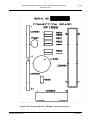
1
NEUROTHERM
RADIO FREQUENCY
LESION GENERATOR
MODEL NT 1100
jService Manual
Neurotherm Radio Frequency Lesion Generator Service Manual
Model NT1100
1.0
CONTENTS
1.1
List of Figures .................................................................................................................. 3
2.0
WARNINGS AND CAUTIONS ......................................................................................... 2-1
3.0
INTRODUCTION AND APPLICABILITY OF THIS MANUAL ........................................... 3-1
3.1
Introduction and applicability of this manual ................................................................. 3-1
3.2
Summary of Equipment Revision Changes .................................................................. 3-2
3.3
Summary of Board Revision Changes ......................................................................... 3-3
3.3.1
Revision A – All Boards
NT1100 .............................................................. 3-3
3.3.2
Revision B – Boards in rack ................................................................................. 3-3
3.4
Manual Updates ........................................................................................................... 3-4
3.4.1
Neurotherm Radio Frequency Lesion Generator Unit Manual Changes .............. 3-4
3.4.2
Record of Manual Updates carried out ................................................................. 3-5
4.0
GENERAL DESCRIPTION AND PRINCIPLE OF LESIONING ....................................... 4-1
4.1
Specifications ............................................................................................................... 4-1
4.2
Principles of Lesioning ............................................................................................... 4-11
4.2.1 The basic physical principles of radiofrequency ablation .......................................... 4-11
4.2.2
Pulsed radiofrequency ........................................................................................ 4-14
4.2.3
The Pulse Dose Concept. ................................................................................... 4-17
4.3
General Description .................................................................................................... 4-22
4.4
General Signal Information ......................................................................................... 4-23
4.5
Connector Panel Layout ............................................................................................. 4-29
4.6
Back Panel Layout ..................................................................................................... 4-30
5.0
DETAILED DESCRIPTION OF MODULES ..................................................................... 5-1
5.1
Power Entry Module, Isolation Transformer and Power Supply Board ........................ 5-1
5.2
Fuse Board ................................................................................................................... 5-3
6.0
CIRCUIT DIAGRAMS AND COMPONENT LISTS ........................................................... 6-1
6.1
6.2
6.3
6.4
6.5
6.6
6.7
6.8
6.9
6.10
6.11
Power Supply Board - RF100C .................................................................................... 6-2
Fuse Board – RF101D ................................................................................................. 6-5
Impedance Board –RF 102D ........................................................................................ 6-8
Stimulate Board RF103D + Sub Board ...................................................................... 6-13
RF Amplifier Board RF 104 C ..................................................................................... 6-19
RF Voltage and Current Metering Board RF 105C..................................................... 6-24
Temperature Board RF106 D ..................................................................................... 6-29
Interlock Board RF107D ............................................................................................. 6-35
Connection Board RF109B......................................................................................... 6-41
Interface Board RF110D ............................................................................................ 6-44
Computer Mother Board RF111B ............................................................................... 6-47
Morgan Automation Ltd
June 2006
Neurotherm Radio Frequency Lesion Generator Service Manual
Model NT1100
1.1
List of Figures
4.1
Output Power/Load Resistance Curve
4.2
Typical available Stimulate Output Voltage/Load Resistance
4.3
Fundamental Radiofrequency Circuit
4.4
Mechanism of Radio Frequency Heating
4.5
Schematic of Tissue Temperature v Distance from Electrode Tip
4.6
Increase in Lesion Size v Time
4.7
Typical Pulsed RF Signal
4.8
Frequency Spectrum of a 2Hz Rectangular Pulse
4.9
Frequency Spectrum of a 500 KHz Signal
4.10
Pulsed RF – Amplitude Control
4.11
Pulsed RF – Pulse Width Control
4.12
Pulse Dose
4.13
General Schematic of the Neurotherm NT1100
5.1
Power Supply Unit - Circuit Diagram
5.2
Fuse Board – Circuit Diagram
Morgan Automation Ltd
June 2006
Neurotherm Radio Frequency Lesion Generator Service Manual
Model NT1100
6.1
Power Supply Board
6.2
-
-RF100C -
Circuit Diagram
Power Supply Board
-RF100C -
Component Layout
6.3
Fuse Board
-RF101D -
Circuit Diagram
6.4
Fuse Board
-RF101D -
Component Layout
6.5
Impedance Board
-RF102D -
Circuit Diagram
6.6
Impedance Board
-RF102D -
Component Layout
6.7
Stimulate Board
-RF103D -
Circuit Diagram
6.8
Stimulate Board
-RF103D -
Component Layout
6.9
RF Amplifier Board
-RF104C -
Circuit Diagram
6.10
RF Amplifier Board
-RF104C -
Component Layout
6.11
V/I Board
-RF105C -
Circuit Diagram
6.12
V/I Board
-RF105C -
Component Layout
6.13
Temperature Board
-RF106D -
Circuit Diagram
6.14
Temperature Board
-RF106D -
Component Layout
6.15
Interlock Board
-RF107D -
Circuit Diagram
6.16
Interlock Board
-RF107D -
Component Layout
6.17
Connection Board
-RF109B -
Circuit Diagram
6.18
Connection Board
-RF109B-
Component Layout
6.19
Interface Board
-RF110D-
Circuit Diagram
6.20
Interface Board
-RF110D-
Component Layout
6.21
Computer Motherboard
-RF111B-
Circuit Diagram – Bus
Interface
6.22
Computer Motherboard
-RF111B-
Circuit Diagram - Digital
Outputs
6.23
Computer Motherboard
-RF111B-
Circuit Diagram-Ribbon
Connectors and PSU
6.24
Computer Motherboard
-RF111B-
Circuit Diagram – Digital
Inputs
6.25
Computer Motherboard
-RF111B-
Circuit Diagram– Analog
Inputs
6.26
Computer Motherboard
-RF111B-
Circuit Diagram– Analog
Outputs
6.27
Computer Motherboard
6.28
Front Panel Wiring
6.29
General System Schematic
Morgan Automation Ltd
-RF111B-
Component Layout
June 2006
Neurotherm Radio Frequency Lesion Generator Service Manual
Model NT1100
2.0
2-1
WARNINGS AND CAUTIONS
Warning indicates a potentially harmful situation to yourself or others.
HAZARDOUS ELECTRICAL OUTPUT: The equipment is for use ONLY by
qualified medical personnel.
Do NOT under any circumstance perform any testing or maintenance on the
equipment while it is being used on a patient.
Do NOT use extension cords or adapters of any type. The power cord and plug
must be intact and undamaged.
Should the power cord or plug become cracked, frayed, broken of otherwise
damaged, it must be replaced immediately.
If the equipment has in any way suffered mechanical damage it should be
returned to the Supplier for Inspection and Test before further use.
Unplug the power cord before cleaning or service.
The operator should not perform any servicing of the equipment. Any servicing
should only be carried out by qualified personnel.
EXPLOSION HAZARD: Equipment not suitable for use in the presence of a
flammable anaesthetic mixture with air or with oxygen or nitrous oxide.
ELECTRIC SHOCK HAZARD: Always turn the equipment off before cleaning
and DO NOT allow ANY fluid to enter the ventilation holes or sockets.
ELECTRIC SHOCK HAZARD: Do not touch any exposed wiring or conductive
surface, while cover is off and the equipment is energised. The voltage present
when the electric power is connected to the equipment can cause injury or death.
Never wear a grounding wrist strap when working on energised equipment.
FUSE REPLACEMENT: For continued protection against fire hazard, replace
only with same type and rating of fuse as displayed on the rear Serial Number
Plate.
IMPROPER LINE VOLTAGE: The voltage selector on the mains input socket is
factory set and should not be changed by the user. The serial number plate
shows the correct mains input voltage for the machine and the rating of the fuses
to be used in the mains input fuse holder. An incorrect voltage setting may result
in Neurotherm malfunction and potential damage.
Morgan Automation Ltd
June 2006
Neurotherm Radio Frequency Lesion Generator Service Manual
Model NT1100
2.0
2-2
WARNINGS AND CAUTIONS (continued)
A CAUTION indicates a condition that may lead to equipment damage or
malfunction.
Servicing of the equipment in accordance with this service manual should never
be undertaken in the absence of proper tools, test equipment and the most
recent revision of this service manual which is clearly and thoroughly understood.
When repairing circuit boards, great care should be taken in handling boards as
all boards contain static sensitive devices. Before servicing a board, ground
yourself and the relevant tool to discharge any accumulated static charge by
wearing a wrist strap and placing the board on a static mat. If a board has to be
returned, use anti-static bags or containers.
The tests and repairs outlined in this manual should only be attempted by trained
personnel. Unauthorised service may void the warranty of the unit.
Check the voltage rating on the rear Serial Number Plate before connecting the
equipment to AC Mains Power. The equipment must never be operated at the
wrong mains voltage.
Use insulated tools when adjusting the internal controls on the equipment.
When cleaning the outer casing or display panel of the equipment do not use
abrasive agents or solvents.
To reduce risk of electrical shock do not remove back panel of generator. Refer
servicing to qualified personnel.
Morgan Automation Ltd
June 2006
Neurotherm Radio Frequency Lesion Generator Service Manual
Model NT1100
3.0
INTRODUCTION AND APPLICABILITY OF THIS MANUAL
3.1
Introduction and applicability of this manual
3-1
This service Manual (Document No. R1000) gives the information
required to maintain and repair the Neurotherm Radio Frequency Lesion
Generator Unit, Model NT1100. The main body of this manual deals
with the present production revision of the equipment. Differences
between equipment revision are summarised in Section 3.2. Section
3.3 lists the technical changes made to the equipment.
The revision of the whole equipment is changed if such technical
changes are made which make some spare parts incompatible with
earlier units. The initial equipment numbering, as shown on the rear
Serial Number Plate contains no revision letter (e.g. Serial No. NT11007020-05) however later revisions will contain a revision letter (e.g.Serial
No. NT1100-7020-05 Rev A). If the whole machine is upgraded such
that early machines cannot be easily amended, then the upgraded
machines will start from a nominated serial number as indicated in
Section 3.2.
Within the equipment, function units such as Printed Circuit Boards will
be changed or updated from time to time, these may or may not
introduce a revision of the whole equipment. Each printed circuit board
contains an identity number and a serial number of the board together
with the issue number - designated by a letter. The initial issue letter
was A for all Boards. In all cases the spare parts order code is also the
Board Identity Number and Issue Number (e.g. RF 102E).
In order to understand this manual it is necessary to have a complete
understanding of the function and operations of the Lesion Generator
Machine. This information can be obtained from the Operators Manual
which contains full operating instructions.
Morgan Automation Ltd
June 2006
Neurotherm Radio Frequency Lesion Generator Service Manual
Model NT1100
3.2
3-2
Summary of Equipment Revision Changes
Initial production revision of this equipment – Model NT1100
Initial production DEC 2005
Start from
NT 1100 – 7007-05
From
NT1100 – 7150 – 06 (May 2006)
Metal Rack used and all cards in rack were changed to move components away
from guides
Morgan Automation Ltd
June 2006
Neurotherm Radio Frequency Lesion Generator Service Manual
Model NT1100
3.3
3-3
Summary of Board Revision Changes
3.3.1
Revision A – All Boards
NT1100
Initial production revision of this equipment
Power Supply Board
Fuse Board
Impedance Board
Stimulate Board
RF Power Amplifier Board
RF Voltage and Current Board
Temperature Board
Interlock Board
Front Panel and Connection Board
Interface Board
Computer Motherboard
Card Rack Backplanes
3.3.2
RF100C
RF101C
RF102C
RF103C
RF104C
RF105B
RF106C
RF107C
RF109B
RF110C
RF111B
RF115A and RF116A
Revision B – Boards in rack
Fuse Board
Impedance Board
Stimulate Board
RF Voltage and Current Board
Temperature Board
Interlock Board
Interface Board
Card Rack Backplanes
Morgan Automation Ltd
RF101D
RF102D
RF103D
RF105C
RF106D
RF107D
RF110D
RF115B and RF116B
June 2006
Neurotherm Radio Frequency Lesion Generator Service Manual
Model NT1100
3.4
3-4
Manual Updates
3.4.1
Neurotherm Radio Frequency Lesion Generator Unit Manual Changes
This is the NT 1100 Manual applicable to the machines from serial numbers shown
below:Issue No.
From
Serial No
Page
NT1100 – 7007-05
2
Morgan Automation Ltd
NT1100 – 7150-06
Change
As issued
Date
DEC 2005
JUNE 2006
June 2006
Neurotherm Radio Frequency Lesion Generator Service Manual
Model NT1100
3.4.2
3-5
Record of Manual Updates carried out
Update Number
2
Morgan Automation Ltd
Carried out by Name
Date
Howard Clarke
June 2006
June 2006
Neurotherm Radio Frequency Lesion Generator Service Manual
Model NT1100
4.0
GENERAL DESCRIPTION AND PRINCIPLE OF LESIONING
4.1
Specifications
4-1
SIZE:
Width
400 mm (15 ¾”)
Height
300 mm (11 ¾”)
Depth
415 mm (16 ½”)
WEIGHT:
12.5 kg
(28 lbs)
ELECTRICAL:
EUROPE
USA/CANADA
230 Volts 50Hz Fused 1 Amp on live and neutral
110 Volts 60Hz Fused 2 Amp on live and neutral
Voltage change via rear connector
Power Consumption
150 watts
The power supply is built to Class 2 standard. The mains transformer and all
mains related parts are doubly insulated from the Main Enclosure. The mains
transformer has separate isolated bobbins for mains and low voltage windings.
Thermal fuses (rated to fail at 125°C) are fitted into all primary and secondary
windings.
The machine is not connected to mains earth (class2).
STANDARDS:
This instrument complies with
EN60601-1:1997
IEC60601-1-2:1993
IEC60601-2-2:1998
IEC60601-2-10: With Canadian deviations
With respect to electrical shock, fire and mechanical hazards only in accordance
with UL60601-1, IEC60601-1, CAN/CSA C22.2 No.601.1 and IEC 60601-2-2
Morgan Automation Ltd
June 2006
Neurotherm Radio Frequency Lesion Generator Service Manual
Model NT1100
4-2
IMPEDANCE
Measuring frequency
53KHz (± 3KHz)
Measuring source voltage
Less than 500 mV AC
Measuring Display
50-2000 ohms (one ohm resolution)
Accuracy
±5%
Features
(a)
(b)
(c)
(d)
Internal 500 ohm Test Resistor
Impedance in all Lesion Modes and in Stimulation
Mode when stimulation is off
Audible Tone available where frequency varies
with impedance over full impedance range (502000 ohms). Audible tone is adjustable and
mutable.
Warning on screen if impedance is less than 50
ohms or greater than 2000 ohms.
STIMULATION MODE
Signal Shape
Biphasic square wave with negative edge leading.
This wave is available in a variety of frequencies and
widths.
Output Range Voltage
0-5v ± 3% for motor frequencies (2Hz and 5 Hz)
0-3v ± 5% (Default) for all other frequencies
0-0.5v ± 10% for all other frequencies
Current
Pulses Rates
Motor
Sensory
0-10mA±5% 50-2000 ohms
0-6mA± 5% 50-2000 ohms
0-1mA± 5% 50-2000 ohms
2 or 5 Hz (Default 2Hz)
10,20, 50, 75, 100, 150, 180, 200 Hz (Default 50 Hz)
Pulse Rate Accuracy
± 3%
Pulse Widths
0.1, 0.2, 0.5 and 1.0 mS (Default 1.0 mS)
Pulse width Accuracy
± 5% for 0.2, 0.5 and 1.0 mS
± 15% for 0.1mS
Morgan Automation Ltd
June 2006
Neurotherm Radio Frequency Lesion Generator Service Manual
Model NT1100
Features
4-3
(a) Hardware and Software lockout if
voltage / current control not initially set
to zero.
(b) Warning on screen if stimulation control
is not
initially at zero.
(c) Flashing LED on front panel indicates
machine is delivering stimulation pulses.
(d) Stimulation Test Socket is provided on
front of machine to interface with the
standard stimulation test kit.
(e) Various screen displays for displaying
amplitude of
each
stimulation procedure.
LESION MODE
RF Waveform
480 KHz ± 5% Sinusoidal
Power Output
Continuously variable. Maximum power output 30
watts ± 5% into 200 ohms. Power is displayed in
certain Lesion Modes.
Voltage Display on screen
0-99RF volts (RMS)
Current Display on screen
0-999RF milliamps (RMS)
Self Test
150 ohm dummy load resistor built into machine
Lamp Indicator
LED flashes when Lesion Power is being delivered.
Temperature Range
Selectable 50-90°C for Thermal Lesion (Default 80°)
Selectable in 5° C steps in initial screen set ups
Selectable in 1°C steps when in Lesion Mode using
“Temp up and Temp down” buttons.
Time
Selectable 0:30 to 10:00 mins (Default 1:00 minute)
Selectable in 30 seconds steps in initial screen set
ups
Selectable in 1 second steps when in Lesion Mode
using “Time up and Time Down” buttons
Special Temperature Profiles
A series of fixed temperature/time profiles are
programmed into the generator: P1, P2, P3. The
user can also program a custom profile with the
following characteristics:
Start Temperature 50-60°C (Default 50°C)
Step Time 00:10 to 3:00 mins (Default 2 mins)
Step Rise 1°C or 5°C (Default 5°C)
Final Temperature 65° - 90° C (Default 65°C)
Final Dwell Time 1:00–10:00 Minutes
(Default 4.00 mins
Morgan Automation Ltd
June 2006
Neurotherm Radio Frequency Lesion Generator Service Manual
Model NT1100
4-4
Lesion Start
Lesion starts as soon as temperature is within 5°C of
desired temperature.
Auto Mode
With Lesion Power Control off, the procedure can be
carried out under Automatic control by pressing the
“Auto start” button. The temperature will ramp up at
8°C per second and time will start when the
measured temperature is within 5°C of desired
temperature.
The lesioning can be stopped at any time by
pressing the “Auto Stop” Button.
Display
Temperature is displayed against time as a curve on
the screen together with a display of “Measured
temperature” and “Time to completion of lesion”. RF
Lesion power (or voltage and current) together with
impedance are also displayed.
Audible Indicator
An alarm tone (with a volume adjustment) will
indicate the end of the procedure.
PULSE RF MODE
In pulsed mode the waveform is pulsed rather than continuous.
Pulse Widths
5ms, 10ms, 20ms, 50ms (default 20 ms)
Pulse Frequencies
1Hz, 2Hz, 5Hz, (default 2 Hz)
Temperature Range
Selectable in 42-65°C range, (default 42°C)
Time
Selectable 00:30 to 20:00 minutes
(default 2:00 mins)
Set Volts/ Current
Pulsed RF can be carried out in Auto Mode at fixed
voltage or current.
Voltage range 30-70 Volts (default 45 Volts)
Current range 50-350 mA
Morgan Automation Ltd
June 2006
Neurotherm Radio Frequency Lesion Generator Service Manual
Model NT1100
4-5
PULSE DOSE MODE
In Pulse Dose Mode the numbers of Pulses of Pulsed RF are counted. Pulse Dose
Procedures are carried out in Auto Mode.
Set Temperature
42°C
Pulse Counts
120-1200 count (Default 240 counts)
Rate
2Hz
Width
20 mS
Set Voltage Range
30-70V (Default 45V)
Set Current Range
50-350 mA
MULTIPLE PROBES
The Neurotherm can be operated with 1,2 or 3 probes. When in Stimulation
Mode each probe is selected by the operator for Stimulation. In RF Lesion,
Pulse RF or Pulse Dose Mode the generator energises all connected probes
in a time interlacing method. In multiple probe operation not all pulse rates are
available.
Features
Morgan Automation Ltd
(a) Hardware and Software lockout if RF Power
Control not initially set to zero.
(b) Warning on screen if RF Control is not
initially set to zero or if Auto is selected and
RF control is not off.
(c) LED Flashes on front panel to indicate
machine is delivering power.
(d) Three output sockets to accept a variety of
probes, (including cordotomy (optional
extra)) and enable multiple probe peration.
(e) Hardware lockout if temperature exceeds 95°C.
June 2006
Neurotherm Radio Frequency Lesion Generator Service Manual
Model NT1100
4-6
MAJOR FEATURES
Touch Screen Operation – User interface set up and software control via TP 400
processor.
Windows CE4.2. NET Operating System.
12.1” LCD Sceen with Back lighting and wide antiglare visibility.
Printer Support
Via Bluetooth adaptor internally fitted.
Remote Mimic
Screen
Optically isolated running over CAT5 Cable to
External TFT screen up to 300 metres.
Storage Device
USB Memory Stick for downloading log files.
Service Ports
Only accessible by service engineers for keyboard +
mouse.
Any equipment connected to rear sockets must comply with IEC60950 and
IEC60601-1
Use only parts supplied by Neurotherm Ltd. Any other parts will void the warranty
and may cause danger to the patient.
Morgan Automation Ltd
June 2006
Neurotherm Radio Frequency Lesion Generator Service Manual
Model NT1100
4-7
Earth Leakage
1
2
3
4
5
6
Enclosure leakage current
Normal
Reverse
Single fault condition
Normal
Reverse
Patient leakage current
Normal (AC)
Reverse (AC)
Single fault condition
Normal (AC)
Reverse AC)
Patient Leakage current
Normal (DC)
Reverse (DC)
Single fault condition
Normal (DC)
Reverse (DC)
Patient Auxiliary Leakage Current
Normal (AC)
Reverse (AC)
Single Fault Condition
Normal (AC)
Reverse (AC)
Patient Auxiliary Leakage Current
Normal (DC)
Reverse (DC)
Single Fault Condition
Normal (DC)
Reverse (DC)
Patient Leakage Floating Type
Normal
Reverse
Single Fault Condition
Normal
Reverse
Morgan Automation Ltd
40 microamsps
40 microamsps
100 microamps
100 microamps
40 microamsps
40 microamps
500 microamps
500 microamps
5 microamps
4 microamps
100 microamps
100 microamps
7 microamps
7 microamps
500 microamps
500 microamps
4 microamps
4 microamps
10 microamps
10 microamps
4 microamps
4 microamps
50 microamps
50 microamps
4 microamps
4 microamps
100 microamps
100 microamps
6 microamps
6 microamps
500 microamps
500 microamps
4 microamps
4 microamps
10 microamps
10 microamps
4 microamps
4 microamps
50 microamps
50 microamps
27 microamps
27 microamps
5000 microamps
5000 microamps
36 microamps
35 microamps
5000 microamps
5000 microamps
June 2006
Neurotherm Radio Frequency Lesion Generator Service Manual
Model NT1100
4-8
Environmental Conditions
7
8
9
Transport
Storage
Operating
Morgan Automation Ltd
Temperature
Humidity
Pressure
-10°C to 70°C
0-95%RH
140-760mmHg
Temperature
Humidity
Pressure
10°C to 60°C
10 to 80% RH
520-760mmHg
Temperature
Humidity
10°C to 40°C
10 to 80% RH
Non-Condensing
(0-12,200 metres)
(0-40, 000ft)
(0-3000 metres)
(0-10,000ft)
June 2006
Neurotherm Radio Frequency Lesion Generator Service Manual
Model NT1100
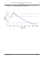
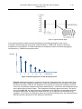
Figure
4.1
4-9
Output Power/Load Resistance Curve
60
50
Wattage
40
30
20
10
0
50
100
150
200
300
500
1000
1200
Impedance
Morgan Automation Ltd
June 2006
Neurotherm Radio Frequency Lesion Generator Service Manual
Model NT1100
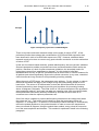
Figure 4.2
4-10
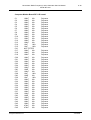
Typical available Stimulation Output Voltage / Load Resistance and
Stimulate Output Current/Load Resistance
Stimulate Output Voltage
(5v Constant Voltage)
Stimulate Output Current
(10mA Constant Current)
100
4.88
10.2
200
4.98
10.2
500
5.04
10.1
1000
5.05
10
2000
5.07
9.84
Load Resistance
0
16
14
Stimulate Output
Current
12
10
8
6
Stimulate Output
Voltage
4
2
0
100
200
500
1000
2000
Load Resistance - Ohms
Morgan Automation Ltd
June 2006
Neurotherm Radio Frequency Lesion Generator Service Manual
Model NT1100
4.2
4-11
Principles of Lesioning
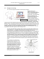
4.2.1 The basic physical principles of radiofrequency ablation
Figure 4.3 shows the
fundamental radiofrequency
circuit. The RF lesion generator
or power source provides a
source of RF. It is connected by
wires to 2 electrodes: one
inserted into the body, referred
to as the active electrode;
another in contact with the
surface of the body, referred to
Figure 4.3 Fundamental
as the dispersive electrode. This
Radio Frequency circuit.
is the so-called monopolar
configuration. The RF voltage
causes current to flow through the wires, through the electrodes, and to the patient’s body. The
patient's body is a conductive electrolytic media, and thus the patient’s body becomes part of the
RF circuit. This current spreads out from the electrodes and flows through the electrolytic tissue
medium of the body. The active and dispersive electrodes have a similar physical role in
delivering and receiving the current, but functionally, because of their differing areas, they have
very different effects with regard to the RF heating process.
The active electrode with its smaller surface area has much higher field densities in the
tissue adjacent to it. This higher field density causes significant heating near the active
electrode surface. The dispersive electrode has a much larger area, and, as a
consequence, the field density is much lower in the tissue adjacent to it. This results in a
lower radiofrequency heating effect, and thus if the dispersive electrode is large enough
no appreciable heating will occur near it. In fact, a large area surface plate to join to the
skin with a conductive gel for good conductivity will not heat appreciably even though this
same radiofrequency current will cause intense heating near the much smaller active
electrode. It is recommended for most radiofrequency procedures that the dispersive
electrode, therefore, should have an area of greater than 150 square centimeters to be
safe from any significant heat elevation when RF lesions delivering 50 watts or less are
used.
The mechanism for radiofrequency
heating is shown in figure 4.4. The
electric field lines emanate from the
active electrode tip and are created by
the voltage impressed upon it by the
radiofrequency generator. This electric
field creates an electric force on the
charged ions within the electrolytic
medium of the tissue. According to the
physics laws this force produces a
motion, and the motion is oscillatory at
the frequency of the RF current.
Figure 4.4 mechanisms for
Radiofrequency heating
Morgan Automation Ltd
June 2006
Neurotherm Radio Frequency Lesion Generator Service Manual
Model NT1100
4-12
It is this radiofrequency motion which causes the ions to rub against the surrounding fluid
medium, causing friction which results in the tissue heating. The temperature at any point is
controlled by the frictionally induced power dissipation at that point, mediated by thermal
diffusion and thermal convection. The thermal diffusion and convection are typically caused by
blood circulation.
The temperature distribution around the electrode tip can be calculated by making certain
simplifying assumptions. One of the assumptions is that the medium is homogeneous and
that the factors of thermal diffusion and circulation are also uniform. Under these
circumstances one can calculate the isotherms (surfaces of constant temperature)
surrounding the electrode tip for a given impressed radiofrequency voltage. These
isothermal surfaces are critical to determining the lesion size. As it is known that living
tissue will be permanently destroyed for sustained temperatures of approximately 45 C, the
45 degree isotherm can be considered to be the outer border of the lesion since tissue
within this volume will be thermally destroyed and tissue outside of this volume will
experience lower temperatures than are necessary for cellular destruction. Isothermal
surfaces are indicated by the -- lines in figure 4.4
It is important to understand that the radiofrequency field, and thus power dissipation in the
tissue actually heats the tissue as opposed to the electrode itself. The heated tissue in turn
raises the temperature of the electrode tip and thus heats the tip. Therefore, it is not the
electrode tip which heats the tissue, but rather the tissue which heats the electrode tip. If
the electrode is properly designed so as not to sink away too much of the thermal energy,
the electrode will give an accurate representation of the tissue temperature at its surface. It
is for this reason that thermal monitoring of the radiofrequency tip is a good indication of the
hottest portion of the lesion volumes, namely the isotherm that lies closest to the surface of
the electrode. With the simplifying assumptions of a homogeneous medium, the lesion size
represented by the 45 degree isotherm increases with increasing tip temperature and also
increases with increasing tip dimension particularly the radius of the electrode tip.
Figure 4.5 Schematic of Tissue Temperature v Distance for Electrode Tip.
Morgan Automation Ltd
June 2006
Neurotherm Radio Frequency Lesion Generator Service Manual
Model NT1100
4-13
Figure 4.5 shows a schematic diagram of the temperature of the tissue as a function of
distance from the electrode tip. It should be noted that the temperature is not isotropic for
a non-spherical electrode, and thus these curves may differ at different orientations on a
non-spherical electrode tip. The temperature at the surface of the electrode, such as T2,
measures very nearly the hottest tissue nearby, and the tissue at greater distances falls
off until it asymptotically approaches body temperature at large distances from the
electrode tip. By raising the radiofrequency voltage, one will increase the temperature to
T1 near the electrode tip, and thus the distances to the 45 C isotherm will increase
accordingly. With knowledge of these characteristics and the temperature vs.distance
curve, one can therefore judge the size of the lesion volumes by choosing the appropriate
tip temperature for a given tip geometry. This is the reason temperature measurement
has been historically essential to produce consistent and quantified lesion volumes.
Measurement of the tip temperature has another very important benefit. By avoiding tip
temperatures near 100 C (the temperature at which water boils), one avoids the undesired
effects of charring, sticking or the formation of a hemorrhage or explosive gas which may
be also be accompanied by sparking. In the early days of neurosurgical lesions, before
reliable tip temperature measurement was possible, neurosurgeons would establish the
end point of their lesion making by listening for the “popping” lesion. The popping was
caused by the tip temperature exceeding 100 C and the subsequent gas formation at the
tip to the electrode. This obviously was not a controlled lesion technique and led to
unpredictable and dangerous destructive conditions.
In pain management there are now well-established prescriptions for appropriate
electrode size and tip temperature to achieve desired lesion volumes. It has been
historically clear that prescriptions which involve power and current did not have lasting
value, but rather prescriptions that involve temperature, electrode size and accounting for
the heat washout caused by blood flow. The importance of temperature control was not
always recognized. For instance, in the early days of percutaneous cervical cordotomy,
elaborate prescriptions of current, power and time for making RF lesions were
established. The subsequent clinical results were not consistent in the early days of
cordotomies, and it was only when temperature was measured at the tip of the cordotomy
electrode that consistency and reproducibility was finally achieved.
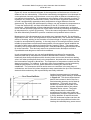
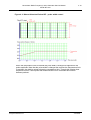
Figure 4.6 Increase in Lesion Size v Time
Morgan Automation Ltd
Another important aspect of controlled
radiofrequency lesion making is illustrated
in Figure 4.6. This shows experimental
data of the increase in lesion size for a
fixed electrode geometry and a fixed tip
temperature. The lesion size in this
situation is defined as the width of the
prolate ellipsoidal width of the prolate
ellipsoidal lesion volume. The graph
clearly shows that for constant tip
temperature the lesion size grows and
asymptotically reaches a maximum value
in a time between 30 and 60 seconds.
The 45C isothermal surface can then be
referred to as the equilibrium lesion size.
Leaving the radiofrequency power turned
June 2006
Neurotherm Radio Frequency Lesion Generator Service Manual
Model NT1100
4-14
on indefinitely beyond 60 seconds will not increase the equilibrium lesion size. In the past,
so-called time-dependent lesions were made in which a certain power was held by the
radiofrequency generator for 10-20 seconds. This too led to inconsistent results, and
resulted in the acknowledgment of the equilibrium lesion size as being the optimum
methodology.
It is noteworthy that impedance monitoring has a great value in assessing the progress of
a heat lesion. The impedance seen by the electrode tip depends on tissue interfaces and
this property has been used very effectively to distinguish between the interface of
electrolytic fluids and tissue. For example this has been used with percutaneous
cordotomy electrodes to clearly tell when the electrode has traversed from the cerebral
spinal fluid to a position of contact with the spinal cord. Impedance monitoring has also
been used to identify when an advancing electrode has progressed from the annulus of
the disk into the nucleus pulposus. The change of impedance during the heating process
is dramatic. It has been shown that as the tissue or medium heats up, the impedance will
drop. This is very much related to the phenomena that the engine oil in an automobile will
become less viscous as the temperature of the engine increases. There is a point,
however, as the temperature at the lesion tip approaches 100 C, when the impedance will
cease to decrease and, in fact, will rise precipitously as the temperature approaches the
boiling point. The reason for this is that the protein coagulation has a rapid onset in this
temperature range causing a decrease in Ionic mobility. Near the boiling point, gas
suddenly forms around the electrode tip, acting as an electrically insulating barrier thus
sending the impedance to very high levels. At the onset of boiling, the impedance rises
very rapidly. In summary, it is clear that the monitoring of temperature and impedance are
both of great significance.
4.2.2
Pulsed radiofrequency
Historically, radiofrequency was neuroablation. This was true for percutaneous
cordotomy, the treatment of trigeminal neuralgia, and the destruction of the medial branch
nerve for facet pain. Mysteries remained however. It was not understood why RF lesions
were so often followed by long periods of discomfort before any beneficial clinical effect
appeared. In the 1990s, additional unanswered questions were added. The mode of
action of RF lesions of the lumbar sympathetic change (other than for vascular disease)
was not understood since there were acceptable success rates, though the results did not
correlate with the degree of sympathetic block.
This led to the hypothesis by Sluijter that heat might not be the element causing the
clinical effect of an RF lesion. The next obvious steps were to define a method to apply
radiofrequency at high intensity without allowing the tip temperature to rise to
neurodestructive levels. The method that was chosen by Sluijter was placing the output
setting of the RF generator in the same range as was customary for making heat lesions
but interrupting the output, thus allowing for sufficient time for the generated heat to be
washed away by thermoconductivity and circulation.
This method has been commonly referred to as pulsed radiofrequency (PRF). Pulsed
radiofrequency is a relatively new technique that applies short pulses of radiofrequency
(20 ms) at a high voltage of 45 to 60 volts to neural tissue. Figure 4.7 shows the currently
accepted paradigm of 20 milliseconds of RF followed by 480 milliseconds of off time. In
this way high intensity radiofrequency is delivered but with a short enough on time so as
not to cause heating above 42 C.
Morgan Automation Ltd
June 2006
Neurotherm Radio Frequency Lesion Generator Service Manual
Model NT1100
4-15
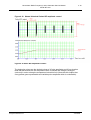
Figure 4.7 Typical Pulsed RF Signal
It is a natural reaction to think of pulsed radiofrequency as being analogous to the neural
modulation effects achieved using spinal cord stimulators or TENS units. However, these two
modalities are very different. In neural modulation the therapeutic effect is achieved by applying
low frequency (< 1000Hz) rectangular pulses.
Strength
2
4
6
8
10
12
Frequency Hz
Figure 4.8 Frequency Spectrum of a 2Hz Rectangular Pulse.
Figure 4.8 shows the frequency spectrum of a two Hz rectangular pulse. As can be seen from
the figure, the major frequency component is at two Hz and falls off as the frequency increases.
At frequencies above 1000 Hz, the amplitude of the frequency component is getting very small.
There is a very different situation with pulsed radiofrequency. In this case, the rectangular pulses
have radiofrequency inside of them. This changes the frequency spectrum entirely. As can be
seen from figure 4.9, the major frequency component is now 500 kHz and decreases at higher
and lower frequencies. At frequencies below 1000 Hz, the contribution can be shown to be
negligible. In conclusion, the frequency spectrums of pulsed radiofrequency are entirely different
than the frequency spectrums of low frequency stimulators.
Morgan Automation Ltd
June 2006
Neurotherm Radio Frequency Lesion Generator Service Manual
Model NT1100
4-16
Strength
500 kHz
frequency Hz
Figure 4.9 Frequency Spectrum of a 500KHZ Signal.
There is very little conclusive research to date on the mode of action of PRF. A few
preliminary studies have shown that a modification of CFOS and DNA expression has
been observed in cells of rat DRG after exposure to PRF. However, additional basic
research needs to be done to come to any good scientific conclusion as to the mechanism
of action of PRF.
In this era of evidence based medicine, pulsed radiofrequency has not yet been validated.
Several retrospective studies and audits have been conducted and the initial results are
positive. Because of a lack of uniform treatment guidelines, the anecdotal results for
pulsed have ranged from magnificent to abysmal. It is this author's belief that
standardization of many of the PRF parameters will at worst result in uniform treatment for
all patients and at best significantly improve the clinical outcomes. In any case, controlled
clinical studies are long overdue for this potentially promising modality.
When the study of PRF began, the parameters were arbitrary. For the voltage, a value is
taken that was within the range of the voltage during the initial heating phase of an RF
heat lesion. The values of 20 milliseconds on time and 480 milliseconds off time were
chosen because they were thought to provide good conditions for preventing heating
above 42 degrees Centigrade. The initial choice of 120 second duration of the procedure
was completely arbitrary, and it was just taken as a starting point. With no scientific basis,
these parameters have been arbitrarily modified by clinicians and thus there is no
consensus as to what the optimum parameters are.
One of the major variables in pulsed radiofrequency treatment is the voltage level when
the pulses are “on”. This arises from the desire to keep the temperature below 42
degrees C. If 42 degrees C. is reached, it is necessary to either manually or automatically
reduce the pulsed amplitude or the pulsed duration in order to ensure the temperature
does not exceed 42 degrees. Using the pulsed dose method, every pulsed is ensured to
be of the same amplitude and duration. This method is explained in detail in the following
paragraph.
Morgan Automation Ltd
June 2006
Neurotherm Radio Frequency Lesion Generator Service Manual
Model NT1100
4.2.3
4-17
The Pulse Dose Concept.
Whenever Pulsed RF is used, if the selected temperature limit is reached, the pulse must
be modified in some way to prevent the selected temperature limit from being exceeded;
this can be done by either.
1. Modifying the pulse amplitude of the pulses- i.e. if a 45 volt amplitude was set, and if
the temperature limit was set to 42 degrees and was reached, the next pulses will be
reduced in voltage to prevent the temperature from increasing above the 42 C
temperature limit.
2. Modifying the pulse width whenever the temperature limit was reached, thus insuring
that each pulse delivered was the full set voltage amplitude.
In Pulse dose the two conditions shown above are avoided. A FULL pulse is always
given, i.e. if the setting is 45 volts amplitude for 20 milliseconds, you will always deliver
this pulse amplitude and duration. If the set temperature limit is reached, the generator
will wait until the temperature drops below the set temperature limit, and then again will
give a FULL amplitude and duration pulse.
Because the generator is only delivering full pulses, in this mode initially one sets the
“number of pulses” that is desired for the procedure as opposed to procedure time, since
procedure time can vary depending on whether the set temperature limit was reached.
The following diagrams depict the different modes-
Morgan Automation Ltd
June 2006
Neurotherm Radio Frequency Lesion Generator Service Manual
Model NT1100
4-18
Figure 4.10 Shows Historical Pulsed RF amplitude control
Figure 10.8
Figure 4.10 Pulse RF Amplitude Control
The beginning pulses are the desired pulses of 45 volts amplitude and 20 ms duration.
Note that the moment the set temperature limit is reached the voltage is changed
(reduced) in order to keep the temperature below this limit. (Note that this implies that
every patient gets unpredictable and variable pulse amplitude which is undesirable).
Morgan Automation Ltd
June 2006
Neurotherm Radio Frequency Lesion Generator Service Manual
Model NT1100
4-19
Figure 4.11 Shows Historical Pulsed RF – pulse width control
When the temperature limit is reached the pulse width is changed as opposed to the
pulse amplitude. Note that the pulse width is changed the moment the temperature limit
is reached, the width is varied to keep the temperature limit. Though this is better than
amplitude control, it still implies that treatments will not be consistent and uniform
between patients.
Morgan Automation Ltd
June 2006
Neurotherm Radio Frequency Lesion Generator Service Manual
Model NT1100
4-20
Figure: 4.12 Shows Pulse Dose- a new more consistent approach.
Figure 10.10
The following diagrams depict the different modesFigure 4.10 Figure Shows Historical Pulsed RF amplitude control
Figure 4.12 Pulse Dose
In the pulse dose mode, only amplitudes that are the full set voltages and widths that are
the full set pulse width are delivered. If the temperature limit is reached, the generator
stops giving output until the temperature falls below the temperature limit. This guarantees
that every treatment delivers the full set amplitude and pulse width. The number of pulses
or “doses” are set by the operator as opposed to time, thus ensuring that every treatment
is consistent patient to patient.
Here is why pulsed dose is superior to the other methods. Imagine doing medial branch
heat lesions and every patient is treated at a different temperature, i.e. one at 80 º C, one
at 70 º C, another at 60 º C. Would you be surprised if this resulted in variable patient
outcomes? Pulsed dose standardizes pulsed RF, just as always using the same
temperature standardizes heat RF.
Morgan Automation Ltd
June 2006
Neurotherm Radio Frequency Lesion Generator Service Manual
Model NT1100
4-21
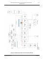
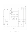
Figure 4.13 General Schematic of the Neurotherm NT1100
Morgan Automation Ltd
June 2006
Neurotherm Radio Frequency Lesion Generator Service Manual
Model NT1100
4.3
4-22
General Description
Figure 4.13 Shows a General Schematic of the Neurotherm NT 1100, and a brief
description of the various Printed Circuit Boards used is given below. A more detailed
description of each board together with its circuit diagram is given in Section 5.
(a)
Mains Input Unit
The Mains Input- - either 115v or 230v comes into the machine via a Corcom
Input Unit which includes Mains Filter, Dual Fuses (1Amp for 230v input, 2
Amp for 115v input), two pole On/Off Switch and Voltage Changing Module.
(b)
Mains Isolating Transformer
Output from the Mains Input Unit goes to a 150w Isolating Transformer which
has the Mains and Low Voltage Windings on two independent isolated
bobbins. Thermal Fuses are fitted on the Mains Input Windings and on each
secondary Winding. Independent Secondary Windings are:67v at 1.25 amp
12v at 2 amp
14v at 2 amp
14v at 1 amp
(c)
AC
AC
AC
AC
Power Supply Board RF100
The Power Supply is located on the bottom baseplate of the machine close to
the transformer and contains full wave rectifier bridges, voltage regulators and
smoothing capacitors to produce a series of DC voltages. These are:90v (75v under load) Rectified and smoothed for Generating RF
15v Rectified and Smoothed for the Computer and Display
12v 2amp Regulated DC for Circuit Boards
-12v 1amp Regulated DC for Circuit Boards and Fan
The Power Supply Board is fully socketed for ease of replacement with
connectors for Transformer, Fan and Rack.
All voltage with the exception of the Fan go to the Fuseboard in the rack.
(d)
Card Rack
The main card rack in the machine contains seven circuit boards and wiring
between the various card is on a 2 section backplane.
Morgan Automation Ltd
June 2006
Neurotherm Radio Frequency Lesion Generator Service Manual
Model NT1100
4-23
Fuse Board RF 101
DC voltages from the power supply go to a Fuse Board which provides
fusing as follows :+ 12 v
- 12 v
+ 90v
+ 15v
2amp for logic (fused 2amp)
1amp for logic (fused 1 amp)
for RF (fused 2amp)
for Computer and Display Section is divided into two
separate 15 v supplies each fused at 2 amps.
Each fused supply has an associated LED which indicates whether the supply
is good (LED – ON) or the fuse is blown (LED – OFF).
All fused supplies are monitored by opto isolated couplers and a “Fuse OK”
signal is monitored by the computer.
4.4
General Signal Information
Motherboard RF111 (Part)
The computer is connected to a motherboard which provides an interface for a series of
Digital and Analogue Input / Output signals. Signals provided are :29 Digital Inputs
47 Digital Outputs
8 Analogue Inputs
4 Analogue Outputs
The Computer operates at 5 volts but interface to the various cards is at 12v DC.
The Motherboard is connected by 2 x 50 way ribbon cables to the Interface Board RF 110.
Interface Board RF110
This board which sits at one end of the rack provides the interconnection between the
computer motherboard, the front panel keyboard and the rack.
The board has no active components It connects into the rack via a 96 way edge
connector and connect to the computer motherboard by 2 x 50 way ribbon cables and to
the Connection Board and front panel keyboard by a 34 way ribbon cable.
Connection Board RF109 and Front Panel Keyboard
The Front Panel Keyboard consists of 14 Membrane Keys with tactile feel 4 of which have
an integral LED. There is also a single ‘Mains’ LED. The Panel also contains two rotary
potentiometers with integral switches (which indicate when the potentiometers are in the
‘off’ position).
The Connection Board is located on the rear of the Front Panel Keyboard. The connection
to the Membrane Keyboard is via a 21 way flat film connector and the connection to the
two potentiometers with integral switches is via a 10 way latched connector. A 34 way
ribbon connector connects the Connection Board to the Interface Board.
Morgan Automation Ltd
June 2006
Neurotherm Radio Frequency Lesion Generator Service Manual
Model NT1100
4-24
A small circuit and sounder are also mounted on the Connection Board to give the “tick” as
time counts down.
Impedance Board RF 102
The Impedance Board measures impedance at the patient using a small 53 KHz signal. Its
input is connected to the Interlock Board and can be switched to measure the impedance
at any of the 3 probe connectors.
The Board contains a 500 Ohm Test Resistor which is switched into circuit during the self
test sequence of the computer to check that the Impedance Circuit is working correctly.
The Board also contains a ‘tone’ circuit whose output frequency is proportional to the
impedance measured and is available if required for cordotomy procedures or during
standard impedance measurements. The volume of the tone can be set up on the
‘Options’ screen of the machine.
Impedance is measured in all lesion procedures and in stimulation mode when no
stimulation signal is present. The output of the board is connected to an analogue input on
the Computer Motherboard and displayed as ohms on the display screen.
Stimulate Board RF 103
The Stimulation Board provides the biphasic stimulation signals used in the Stimulation
‘Motor’ or ‘Sensory’ modes of the machine.
The board produces the following “frequencies” and “widths” of stimulation pulse.
Frequencies
Sensory 10,20, 50, 75,100, 150, 180, 200 Hz
Motor 2Hz or 5Hz
Pulse Widths
0.1 mS, 0.2 mS, 0.5 mS, 1 mS
These frequencies and pulse widths are selected by user via the appropriate “screens”
and selected on the board via an appropriate BCD code from the computer via its Digital
Outputs.
In a similar way the maximum pulse height and whether the pulse is a voltage or current
pulse is selected via computer Digital Outputs.
The outputs available are 0-0.5v, 0-3v, 0-5v
and 0-1mA, 0-6mA, 0-10mA
The board also contains a tone circuit which is connected to the test socket on the front of
the machine and is used via the test block to check stimulation pulses appear at a probe.
The stimulation circuit can be connected to any of the 3 probe input sockets on the front
of the machine as selected by the user.
Morgan Automation Ltd
June 2006
Neurotherm Radio Frequency Lesion Generator Service Manual
Model NT1100
4-25
A hardware interlock is fitted to prevent stimulate pulses being emitted when the
stimulation mode is selected and the voltage/current control is not initially set to zero. This
circuit is in addition to the software interlock.
The flashing LED on the appropriate stimulate mode “select” button operates when output
is present ( this is controlled by software).
The output from the board is connected to an analogue input on the Computer
Motherboard and displayed on the display screen.
Temperature Board RF106
The temperature Board measures the temperature at any selected output and controls the
power sent to a probe by switching it off when a selected temperature is reached. The
input to the board is from the three probe sockets on the front panel of the machine.
The board contains a single temperature measuring circuit and which probe is connected
to it is controlled by the computer.
In procedures, where multiple probes are connected to the machine the single
temperature circuit is switched between probes.
The temperature circuit is designed for Type K Thermocouples and the small signal from
the selected probe is passed via a multi stage low pass filter to a Monolithic Thermocouple
Amplifier with Cold Junction Compensation. This Thermocouple Amplifier is also
connected to a Temperature Compensation Board mounted on the rear of the probe
sockets which effectively moves the Cold Junction Compensation point from the
Temperature Board to the Probe Socket and hence avoids any errors due to temperature
rise within the Neurotherm.
The output from the Thermocouple Amplifier is approximately 0-1v for 0-100 °C , the
voltage is then multiplied x 2 to give a 0-2v signal to an analogue input of the computer to
display the appropriate temperature.
The computer (via one of its analogue outputs) sends out a 0-2v signal to represent the
temperature the user has selected to control to. This signal is compared with the
measured temperature signal and when the measured signal approaches the control
temperature the Board sends an excess temperature signal to the RF Power Amplifier to
shut down the RF. This control of the Power Amplifier is made via hardware and the
computer does not form part of the control loop.
The measured temperature is also compared with a 95°C set temperature and if the
measured temperature gets to 95° C the Power Amplifier output is shut down and the RF
is also isolated from the patient via a relay. This safety circuit is also a hardware only
lockout.
The Temperature Board also contains the circuitry to generate the frequencies and pulse
widths for Pulsed RF. The following frequencies and pulse widths are provided
Frequency 1, 2, 5, 10 Hz
Pulse Width 5, 10, 20, 50 mS
Morgan Automation Ltd
June 2006
Neurotherm Radio Frequency Lesion Generator Service Manual
Model NT1100
4-26
These frequencies and pulse widths are selected by the user via the appropriate “screens”
and selected on the board via an appropriate BCD code from the computer via its Digital
Outputs.
These pulse frequencies are also used as primary switching frequencies for the interlacing
of impedance measurement during RF Lesioning, and are used for this purpose on the V/I
Board.
RF Power Amplifier RF104
The RF Power Amplifier is located on the base of the machine and uses the air flow from
the fan to directly cool its integral heat sink. The Amplifier produces a sine wave output
which is a constant voltage over a very wide patient impedance range. The Amplifier is set
to give 30 watts at 200 ohm load.
The output voltage of the Amplifier is approximately 0-75 Vrms for a DC input of 0-5 volts.
In Manual Mode this DC voltage comes from the RF Power Control on the Front Panel,
but when the Amplifier is in Auto Mode the voltage is provided by one of the Analogue
Outputs of the computer.
The amplifier also has a Low Power Mode which is switched on when a Cordotomy
Treatment is being used.
Output from the Amplifier is enabled both by hardware and software and both signals have
to be enabled for output to be present. The Hardware Enable is used for Impedance
Interlacing, Pulsed RF, Temperature Control, 95°C Excess Temperature and Hardware
Interlock.
The Software Enable is given when the machine is in the correct operating state, no errors
have been monitored by the computer and the Computer Watchdog Timer is running
correctly.
The Amplifier Board is designed to be tolerant to a shorted output and will cut out if the
board detects over-temperature. If the Board detects a failure it sends an error signal to
the Computer which will be displayed.
V/I Board RF105
The V/I Board has several different functions, these are:a)
b)
c)
d)
Provide the 75v for the RF Power Amplifier
Measure the RF Current and RF Voltage being delivered by the RF
Amplifier.
Switching RF Power to a Test Load
Provide timing circuit for interlacing the Impedance and RF Signals
The 75V DC Voltage from the Power Supply Board is fused on the Fuse Board and then
goes to the V/I Board. When a condition that RF is required is determined by the
computer, an “RF ON Enable” signal is sent from the computer and switches the 75V DC
through to the RF Power Amplifier. (RF Power at this point is not switched to the patient a
whole series of conditions have to be met for this to occur).
Morgan Automation Ltd
June 2006
Neurotherm Radio Frequency Lesion Generator Service Manual
Model NT1100
4-27
RF Signal sinewave at 480KHz comes onto the Board from the RF Power Amplifier and its
Voltage and Current are detected by two toriod coils, the output of each is full wave
rectified and produces a DC Output Voltage which is proportional to the RF Voltage and
Current from the Power Amplifier. These voltages go to two Analogue Inputs on the
Computer Motherboard and are used to display RF Voltage and RF Current.
Under normal circumstances the output RF is fed to an external 150ohm 100 watt Test
Load fixed in the base of the machine and only passes to the Interlock Board when a
“Disconnect Test Load” signal is received from the computer.
In order to measure the Impedance of the patient when RF is present it is necessary to
turn off the RF for about 25mS twice a second. The circuitry to carry out this signal
interlacing is contained on the V/I Board. The key stages of measurement are:a)
b)
c)
d)
e)
f)
Disconnect RF from patient
Connect Impedance Measuring Circuit
Wait for signal to stabilise and then sample and hold the reading
Disconnect Impedance Circuit
Reconnect RF
Sample RF
Then 500 ms later
Hold RF Signal
Disconnect RF from patient etc.
g)
h)
This interlacing procedure is triggered by pulses from the Temperature Board, so that
when the machine is in pulsed or dosed RF Modes, the temperature measurement is
carried out during the “off period” of the RF.
Interlock Board RF107
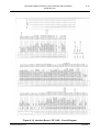
The Interlock Board provides the main final interlock to only allow RF to go to the patient if
all key conditions are met. It is also the point where switching of RF between outputs
occurs.
RF arrives at the board from the V/I Board and then passes to the patient via a safety
relay and then a series of relays which select which output should be activated.
In order for the safety relay to operate the following conditions have to be met
a)
b)
c)
d)
e)
f)
A lesion must have started and not be timed out
The Temperature Board must not have detected a temperature in excess of 95° C
The Computer Watchdog Timer must be running
Pulse or Lesion Mode must have been selected
If Auto Start has been selected, RF Control is turned off (fully anticlockwise)
Auto Stop has not been pressed.
If all the conditions for the safety relay are met the RF signal is switched to 3 relays which
control which outputs of the machine receives an RF signal. This is under the control of
the computer, as when multiple outputs are used the RF is switched to each output in turn.
When operating with Dual Probes and a lesion is made between two electrodes, one of
the outputs of the machine is switched to act as the dispersive.
Morgan Automation Ltd
June 2006
Neurotherm Radio Frequency Lesion Generator Service Manual
Model NT1100
4-28
When a procedure is completed, an alarm tone is sounded. The volume of this alarm can
be set up on the “Options” Screen of the machine, and the computer generates the
appropriate Analogue Output Signal to activate the required volume on the board.
Computer Board and Ancillary Boards
The Computer Board is a PC104 Single Board Computer with a 5 watt requirement, so
forced air cooling of the computer is not required. The board contains interfaces which
include USB, TFT Display, Keyboard, Mouse, Serial Port for Touchscreen and Flash
Memory. Its link to the machine is via its 64 way PC104 Interface Connector which
connects directly into the Computer Motherboard. Some interfaces, for example, the USB
Memory Stick, Remote Screen and Printer Bluetooth Adaptor connect from the computer
card to the Adaptor Board TP400 via a short 50 way ribbon cable.
The Adaptor Board which is mounted on the Motherboard (but not connected to it)
provides external connections at the rear of the machine. Two other connections for
keyboard and mouse for engineers use only are also provided.
The Computer Board has a small sub-board into which the 128 MB Flash Memory Card is
plugged, this memory contains the working system software for the machine and a
segment of its memory is used to store the readings from procedures for later
downloading to the memory stick.
The computer also connects directly to the TFT Display and Touchscreen. For the TFT
Display the connection goes via a small link board which reorders the pins numbers and
connectors so that ribbon cables can be used. The Touchscreen goes via a small Driver
Board which enables the touchscreen to connect to the RS232 interface of the computer.
The TFT Display has back illumination which is provided by a small inverter board
mounted on the rear of the display; this inverter gets a 12vDC signal from the Computer
Motherboard.
The rationale of using a number of small interface boards for the display and touchscreen
is that if at some stage in the future the computer, touchscreen or display were changed,
then the only boards requiring modification would be the small interface board or Adaptor
Board.
Morgan Automation Ltd
June 2006
Neurotherm Radio Frequency Lesion Generator Service Manual
Model NT1100
4.5
4-29
Connector Panel Layout
Dispersive Socket
This 4mm socket is for the lead of the Dispersive Patient Plate which should be at least
200 sq cm (21 square inches).
Test Socket
This 2mm socket is used to connect the Test Block for use in testing the thermocouple
probes in the Stimulate Mode.
Probe Socket No 1
This 4 pin socket is used to connect single electrodes for standard RF Lesion and Pulsed
RF Lesion Procedures.
Probe Socket No 2
This 4 pin socket is used to connect electrodes used for ‘special’ procedures .
Probe Socket No 3
This 4 pin socket is used to connect electrodes used for ‘special’ procedures.
[Special procedures include two and three electrode procedures, dual electrode
procedures, bipolar electrode procedures and cordotomy procedures]
Morgan Automation Ltd
June 2006
Neurotherm Radio Frequency Lesion Generator Service Manual
Model NT1100
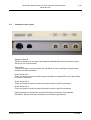
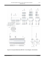
4.6
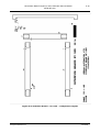
Back Panel Layout
4-30
5
A
B
C
D
7
4
6
1
2
3
1.
Mains On/Off Switch
This is a rocker type switch, combined with an I.E.C. connector socket with twin ‘inline’ anti-surge fuses in a single unit to IEC 950
2.
Mains IEC Connector
The three pin plug of the mains must be pushed into this socket. This cannot be
done incorrectly i.e. with the live and neutral reversed because of the orientation of
the unused earth pin.
3.
Fuses and Voltage Changes
The Neurotherm is protected by two in-line fuses, one on the live line and one on
the neutral line. These fuses are located to the right hand side of the IEC socket.
The fuses are 20mm Anti-Surge to BS 4265. 1 amp for 230v supply, 2 amps for
115v supply. To access the fuse holder lift protective lid from the right hand edge
and hinge back, the fuse carrier can then be removed. The mains input unit also
contains a small printed circuit card which allows the mains input voltage to be
changed [Note this is for factory setting only and should not be altered]
4.
Serial Plate
This plate gives information on Rated Supply, Rated Power, Fuse Ratings and the
Machine Serial Number.
5.
Rear Connector
Depending on the options chosen, there are a series of connectors on the rear of
the generator, some which are available to the operator and some which are
covered over with a protective cover.
Morgan Automation Ltd
June 2006
Neurotherm Radio Frequency Lesion Generator Service Manual
Model NT1100
4-31
Connector A- Memory socket available on all machines for use only with
Neurotherm Memory Stick (NT-USB). DO NOT CONNECT ANY OTHER DEVICE
TO THIS SOCKET AS IT WILL COMPROMISE THE SAFETY OF THE PATIENT
Connector B- ‘Video Out’ socket- available on some machines for use only with
Neurotherm Video Unit (NT-VD) - this unit provides opto-isolated connection to a
remote display. DO NOT CONNECT ANY OTHER DEVICE TO THIS SOCKET
AS IT WILL COMPROMISE THE SAFETY OF THE PATIENT
Connector C- Remote keyboard- this connector is covered over and is a keyboard
connection for service engineers only.
Connector D- Remote Mouse- this connector is covered over and is a mouse
connection for service engineers only.
6.
Contact Address
If the Neurotherm requires a routine service or in the unlikely event of the machine
malfunctioning, the contact address of Neurotherm Ltd is shown on the back plate.
The full address, telephone and contact details are shown in Section 11.
7.
Ventilation Apertures
These apertures are to ensure the correct air circulation within the generator and
should not be blocked or obstructed.
Morgan Automation Ltd
June 2006
Neurotherm Radio Frequency Lesion Generator Service Manual
Model NT1100
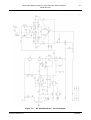
5.0
DETAILED DESCRIPTION OF MODULES
5.1
Power Entry Module, Isolation Transformer and Power Supply Board
5-1
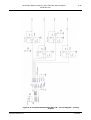
Referring to Figure 5.1 Mains Power is connected into the rear of the equipment and goes via a
Medical Filter to a double pole On/Off Switch and then via two fuses to a voltage selector which is
connected to the main Isolating Transformer TR1.
The Voltage Selector Unit is a small printed circuit card which allows the mains input voltage to be
changed. {Note. It is for factory setting only and should not be altered.}
The Isolation Transformer is of a double bobbin type and has four secondary windings namely:
Winding 1
Winding 2
Winding 3
Winding 4
67v
12v
14v
14v
1.25A
2A
2A
1A
The transformer is fitted with thermal fuses on all primary and secondary windings.
The transformer secondary windings are connected onto the Power Supply Board via an 8way
Connector CON I.
The Power Supply Board provides the following supplies:
(a)
90v (75v under load) Rectified and Smoothed for generating the RF Power.
(b)
15v Rectified and Smoothed for powering the computer and display via supplies on
the Computer Motherboard.
(c)
12v 2 amp regulated DC for the circuit boards
(d)
-12v amp regulated DC for the circuit boards and fan.
A 10 way connector (CON 2) is provided for connection of all DC voltages to the
Card Rack and 3 way connector (CON 3) is provided for connection of the main
cooling fan.
Morgan Automation Ltd
June 2006
Neurotherm Radio Frequency Lesion Generator Service Manual
Model NT1100
Morgan Automation Ltd
5-2
June 2006
Neurotherm Radio Frequency Lesion Generator Service Manual
Model NT1100
5-3
Figure 5.1 Power Supply Unit – Circuit Diagram
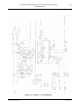
5.2
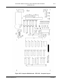
Fuse Board
Referring to Figure 5.2
DC voltages from the Power Supply Board go to the Fuse Board which provides fusing for the
various supplies together with LED indication of the status of the each supply (LED ON – Supply
Healthy) and Test Points for monitoring and fault finding.
The fusing provided is:
F101
F102
F104
F105
F106
+12V
-12V
+90V
+15v
+15v
for logic fused 2 amps
for logic fused 1 amp
for RF Power fused 2 amps
for Computer supply (5v) fused 2 amps
for Display Illumination fused 2 amps
Test points provided are:
TP 1
TP2
TP3
+12v
0v
-12v
TP5
TP6
+90v
0v
RF Power
TP7
TP8
TP9
+15v
0v
+15v
Supplies to Computer
Motherboard
Logic
The LED indication is:
LED
LED
LED
LED
LED
101
102
104
105
106
+12v
-12v
+90v
+15v
+15v
Logic
Logic
RF Power
Computer 5v
Display Illumination
All supplies are connected on their secondary side (after the appropriate fuse) to a Quad Opto
Isolated Coupler which produces a digital input to the computer to indicate that all supplies are
present. The signal “Fuses OK” goes to Digital Input C3 and is high when all supplies are present.
Morgan Automation Ltd
June 2006
Neurotherm Radio Frequency Lesion Generator Service Manual
Model NT1100
5-4
Figure 5.2 Fuse Board – Circuit Diagram
Morgan Automation Ltd
June 2006
Neurotherm Radio Frequency Lesion Generator Service Manual
Model NT1100
Morgan Automation Ltd
5-5
June 2006
Neurotherm Radio Frequency Lesion Generator Service Manual
Model NT1100
5-6
Figure 5.3 Impedance Board – Circuit Diagram
Figure 5.4
Morgan Automation Ltd
Stimulate Board – Circuit Diagram
June 2006
Neurotherm Radio Frequency Lesion Generator Service Manual
Model NT1100
Figure 5.5
Morgan Automation Ltd
5-7
RF Amplifier Board – Circuit Diagram
June 2006
Neurotherm Radio Frequency Lesion Generator Service Manual
Model NT1100
5-8
Figure 5.6 V/I Board – Circuit Diagram
Morgan Automation Ltd
June 2006
Neurotherm Radio Frequency Lesion Generator Service Manual
Model NT1100
Figure 5.7
Morgan Automation Ltd
5-9
Temperature Board – Circuit Diagram
June 2006
Neurotherm Radio Frequency Lesion Generator Service Manual
Model NT1100
Figure 5.8
Morgan Automation Ltd
5-10
Interlock Board – Circuit Diagram
June 2006
Neurotherm Radio Frequency Lesion Generator Service Manual
Model NT1100
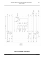
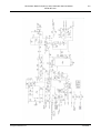
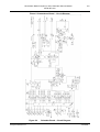
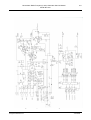
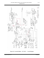
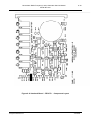
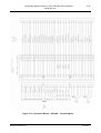
6.0
6-1
CIRCUIT DIAGRAMS AND COMPONENT LISTS
This section contains details of circuit boards, and general wiring:a)
Component Lists
b)
Circuits
c)
Board Layouts
Details are included for the following Boards:a)
Power Supply Board
RF100C
b)
Fuse Board
RF101D
c)
Impedance Board
RF102D
d)
Stimulate Board
RF103D
e)
RF Generator Board
RF104C
f)
RF Voltage and Current Board
RF105D
g)
Temperature Board
RF106D
h)
Interlock Board
RF107D
i)
Interface Board
RF110C
j)
Front Panel and Connection
RF109B
k)
Computer Motherboard
RF111B
Morgan Automation Ltd
June 2006
Neurotherm Radio Frequency Lesion Generator Service Manual
Model NT1100
6.1
6-2
Power Supply Board - RF100C
Components
R1
R2
4K7±5%
4K7±5%
1/4 watt
1/4 watt
Carbon Film
Carbon Film
C1
C2
C3
C4
C6
C7
C8
C9
C11
C12
C13
C14
C15
C16
C17
3300MF
4700MF
4700MF
4700MF
470nF
470nF
470nF
470nF
470nF
470nf
100nF
470nF
470nF
100nF
470MF
160v
63v
25v
25v
100v
100v
100v
100v
63v
63v
63v
63v
63v
63v
16v
Electrolytic
Electrolytic
Electrolytic
Electrolytic
Polyester
Polyester
Polyester
Polyester
Polyester
Polyester
Polyester
Polyester
Polyester
Polyester
Electrolytic
REC1
REC2
REC3
REC4
6 amp
6 amp
6 amp
6 amp
REG
REG
CON1
CON2
CON3
Rectifier Bridge
Rectifier Bridge
Rectifier Bridge
Rectifier Bridge
78S12
7912
8 way
10 way
3 way
2 amp
1 amp
Connector
Connector
Connector
KBPC 602
KBPC 602
KBPC 602
KBPC 602
Regulator
Regulator
Molex 39-26-3080
Molex 39-26-3100
Molex 39-26-3030
TP1-TP7 PCB Test Points
The two regulators are each mounted on heatsinks Heatsink type SW38-4
Morgan Automation Ltd
June 2006
Neurotherm Radio Frequency Lesion Generator Service Manual
Model NT1100
6-3
Figure 6.1 Power Supply Board – RF100 C – Circuit Diagram
Morgan Automation Ltd
June 2006
Neurotherm Radio Frequency Lesion Generator Service Manual
Model NT1100
6-4
Figure 6.2 Power Supply Board –RF100 C – Component Layout
Morgan Automation Ltd
June 2006
Neurotherm Radio Frequency Lesion Generator Service Manual
Model NT1100
6.2
6-5
Fuse Board – RF101D
R101
R102
R104
R105
R106
R107
R108
R109
R110
R111
R112
R113
R114
4K7±5%
4K7±5%
27K±5%
6K8±5%
6K8±5%
IK±5%
8K2±5%
1K2±5%
1K2±5%
2K2±5%
2K2±5%
4K7±5%
10k±5%
T101
BC337
U101
4 way Transistor Output Opto Isolator Type KP1040E
LED
LED
LED
LED
LED
F
F
F
F
F
101
102
104
105
106
101
102
104
105
106
0.25 watt
0.25 watt
0.25 watt
0.25 watt
0.25 watt
0.25 watt
0.25 watt
0.25 watt
0.25 watt
0.25 watt
0.25 watt
0.25 watt
0.25 watt
Carbon Film
Carbon Film
Carbon Film
Carbon Film
Carbon Film
Carbon Film
Carbon Film
Carbon Film
Carbon Film
Carbon Film
Carbon Film
Carbon Film
Carbon Film
NPN Transistor
Low power 5mm Board Indicators-Green
Open Fuse holders with Covers
Test Points TP1 –TP9 PCB Test Terminals
Black Handle
Edge Connector
Morgan Automation Ltd
DIN 41612
Type D 32 Way
June 2006
Neurotherm Radio Frequency Lesion Generator Service Manual
Model NT1100
6-6
Figure 6.3 Fuse Board – RF101 D – Circuit Diagram
Morgan Automation Ltd
June 2006
Neurotherm Radio Frequency Lesion Generator Service Manual
Model NT1100
6-7
Figure 6.4 Fuse Board – RF 101 D – Component Layout
Morgan Automation Ltd
June 2006
Neurotherm Radio Frequency Lesion Generator Service Manual
Model NT1100
6.3
6-8
Impedance Board –RF 102D
Components
R201
R202
R203
R204
R205
R206
R207
R208
R209
R211
R212
R213
R214
R215
R216
R217
R218
R219
R220
R221
R222
R223
R224
R225
R226
R227
R228
R229
R230
R231
R232
R233
R234
R235
R236
R237
R239
R240
R241
R242
2K
7K5
6K8
6K8
82K
15K
3K16
3K16
180R
3K16
10K
10K
3K3
3K3
3K3
470K
330K
200K
100K
2K2
47R
10K
330K
499R
10R
1K
3K
12K
100R
4K7
200R
10K
33K
1K
10K
4K7
LINK
1K
39R
10K
P201
P202
P203
1K
20K
5K
Morgan Automation Ltd
±5%
±5%
±5%
±5%
±5%
±5%
±0.5%
±0.5%
±5%
±0.5%
±5%
±5%
±5%
±5%
±5%
±5%
±5%
±5%
±5%
±5%
±5%
±5%
±5%
±0.1%
±5%
±5%
±5%
±5%
±5%
±5%
±5%
±5%
±5%
±5%
±5%
±5%
0.25 W
0.25 W
0.25 W
0.25 W
0.25 W
0.25 W
0.25 W
0.25 W
0.25 W
0.25 W
0.25 W
0.25 W
0.25 W
0.25 W
0.25 W
0.25 W
0.25 W
0.25 W
0.25 W
0.25 W
1 Watt
0.25 W
0.25 W
0.25 W
0.25 W
0.25 W
0.25 W
0.25 W
0.25 W
0.25 W
0.25 W
0.25 W
0.25 W
0.25 W
0.25 W
0.25 W
Carbon Film
Carbon Film
Carbon Film
Carbon Film
Carbon Film
Carbon Film
Precision Metal Film
Precision Metal Film
Carbon Film
Precision Metal Film
Carbon Film
Carbon Film
Carbon Film
Carbon Film
Carbon Film
Carbon Film
Carbon Film
Carbon Film
Carbon Film
Carbon Film
Carbon Film
Carbon Film
Carbon Film
Precision Metal Film
Carbon Film
Carbon Film
Carbon Film
Carbon Film
Carbon Film
Carbon Film
Carbon Film
Carbon Film
Carbon Film
Carbon Film
Carbon Film
Carbon Film
±5%
±5%
±5%
0.25 W
0.25 W
0.25 W
Carbon Film
Carbon Film
Carbon Film
Potentiometer 18 turn
Potentiometer 18 turn
Potentiometer 18 turn
June 2006
Neurotherm Radio Frequency Lesion Generator Service Manual
Model NT1100
6-9
Impedance Board – RF 102D contd
P204
P206
50K
200K
C201
C202
C203
C204
C205
C208
C210
C211
C212
C213
C214B
C215
C216
C217
C218
C219
C220
C221
C224
C225
C226
C229
C230
1000pF
120pF
1000pF
1000pF
4.7nF
330nF
220pF
1nF
2.2nF
1nF
1800pF
100MF
100nF
100nf
100nF
47MF
100nF
100nF
100nF
100nF
47MF
100nF
10MF
D202
D203
D204
D205
D206
D207
D208
D209
D210
D211
D212
D213
D214
D215
D216
D218
D219
BAT85X
IN4148
IN4148
IN4148
IN4148
IN4148
IN4148
IN4148
IN4148
BAT85
BAT85
ZXR125ER
IN4002
IN4148
LED Amber
ZXR 125ER
ZXR125ER
1.2V Reference Diode
1.2V Reference Diode
TR201
TR202
TR203
BC559
MPSA13
MPSA13
PNP Transistor
Darlington
Darlington
Morgan Automation Ltd
Potentiometer 18 turn
Potentiometer 18 turn
±1%
±1%
±1%
±1%
100V
63V
100V
100V
100V
±1%
16V
63V
63V
63V
16V
63V
63V
63V
63V
16V
63V
16V
Silver Mica
Silver Mica
Silver Mica
Silver Mica
Polyester
Polyester
miniature plate ceramic
Ceramic
Ceramic
Ceramic
Silver Mica
Electrolytic
Polyester
Polyester
Polyester
Electrolytic
Polyester
Polyester
Polyester
Polyester
Electrolytic
Polyester
Electrolytic
1.2V Reference Diode
June 2006
Neurotherm Radio Frequency Lesion Generator Service Manual
Model NT1100
6-10
Impedance Board – RF102D contd
U201
U202
U203
U204
U206
U207
ICL 8038 CCPD
TL072N
TL072N
TC9402CPD
LF398N
LM741CN
L201
L202
470µH
470µH
TF201
PT4
T 201
Thermistor 100K at 25°C NTC Type
LS201
Loudspeaker 8ohm 40mm dia 200mW
RL201
RL202
RL203
RL204
RL205
RL206
12V
12V
12V
12V
12V
12V
TP1-TP3
Test Points
64
Frequency Generator
Dual Amplifier
Dual Amplifier
Voltage to Frequency Converter
Sample/Hold
Operation Amplifier
1:1 Pulse Transformer
Low Power 2 pole relay
Reed Relay
Reed Relay
Low Power 2 pole relay
Low Power 2 pole relay
Low Power 2 pole relay
Way Connector DIN416 Type D 32 way ac
Handle - White
Morgan Automation Ltd
June 2006
Neurotherm Radio Frequency Lesion Generator Service Manual
Model NT1100
6-11
Figure 6.5 Impedance Board – RF102 D – Circuit Diagram
Morgan Automation Ltd
June 2006
Neurotherm Radio Frequency Lesion Generator Service Manual
Model NT1100
6-12
Figure 6.6 Impedance Board – RF102 D – Component Layout
Morgan Automation Ltd
June 2006
Neurotherm Radio Frequency Lesion Generator Service Manual
Model NT1100
6.4
6-13
Stimulate Board RF103D + Sub Board
R301A-F
R302A
R302B
R303A
R303 B
R304A
R304B
R305A
R305B
R306A
R306B
R307A
R307B
R308A
R308B
R309A
R309B
R310A
R310B
R311A
R311B
R312
R313
R314
R315
R316
R317
R318
R319
R320
R321
R323
R324
R325
R326
R327
R330
R331
R332
R335
R336
R337
R338
R339
R340
R341
R342
10K
698K
16K2
280K
K6
140K
2K7
68K
3K24
28K
442R
16K2
2K7
14K
133R
9K1
274R
7K5
287R
6K8
191R
9K1
18K
45K3
91K
9K1
18K
45K3
91K
10K
10K
1K
2K4
4K7
1K5
1K5
18K
10K
10K
39K
22R
33K
470R
1M
4K7
27R
LINK
±1%
±1%
±1%
±1%
±1%
±1%
±1%
±1%
±1%
±1%
±1%
±1%
±1%
±1%
±1%
±1%
±1%
±1%
±1%
±1%
±1%
±1%
±1%
±1%
±1%
±1%
±1%
±1%
±5%
±5%
±1%
±1%
±5%
±5%
±5%
±1%
±1%
±1%
±1%
±5%
±1%
±5%
±5%
±5%
±5%
7
0.6 watt
0.6 watt
0.25 watt
0.25 watt
0.6 watt
0.25 watt
0.25 watt
0.6 watt
0.6 watt
0.6 watt
0.6 watt
0.25 watt
0.6 watt
0.6 watt
0.25 watt
0.6 watt
0.25 watt
0.6 watt
0.25 watt
0.6 watt
0.25 watt
0.25 watt
0.6 watt
0.25 watt
0.25 watt
0.25 watt
0.6 watt
0.25 watt
0.25 watt
0.25 watt
0.25 watt
0.25 watt
0.25 watt
0.25 watt
0.25 watt
0.25 watt
0.25 watt
0.25 watt
0.25 watt
2.5 watt
0.25 watt
0.25 watt
0.25 watt
0.25 watt
0.25 watt
Bussed Resistors SIL
Metal Film
Metal Film
Metal Film
Metal Film
Metal Film
Metal Film
Metal Film
Metal Film
Metal Film
Metal Film
Metal Film
Metal Film
Metal Film
Metal Film
Metal Film
Metal Film
Metal Film
Metal Film
Metal Film
Metal Film
Metal Film
Metal Film
Metal Film
Metal Film
Metal Film
Metal Film
Metal Film
Metal Film
Carbon Film
Carbon Film
Metal Film
Metal Film
Carbon Film
Carbon Film
Carbon Film
Metal Film
Metal Film
Metal Film
Metal Film
vitreous
Metal Film
Carbon Film
Carbon Film
Carbon Film
Carbon Film
Stimulate Board RF103D + Sub Board contd
Morgan Automation Ltd
June 2006
Neurotherm Radio Frequency Lesion Generator Service Manual
Model NT1100
R343
R344
R345
R346
R347
R348
R349
R350
R351
R352
R353
R354
R355
R356
R357
R358
R359
R361
R362
R363
R364
R365
R366
R367
R368
5K1
4K7
10K
10K
3K3
10K
2K
100R
75K
1K
680R
12K
12K
470K
330R
10K
150R
4K7
10K
8K2
1K
2K
6K2
100R
9K1
±5%
±5^%
±5%
±5%
±5%
±5%
±5%
±5%
±5%
±5%
±5%
±5%
±5%
±5%
±5%
±5%
±5%
±5%
±1%
±1%
±1%
±1%
±1%
±1%
±1%
0.25 watt
0.25 watt
0.25 watt
0.25 watt
0.25 watt
0.25 watt
0.25 watt
0.25 watt
0.25 watt
0.25 watt
0.25 watt
0.25 watt
0.25 watt
0.25 watt
0.25 watt
0.25 watt
0.25 watt
0.25 watt
0.25 watt
0.25 watt
0.25 watt
0.25 watt
0.25 watt
0.25 watt
0.25 watt
P302
P303
P305
P306
P307
P308
2K
5K
20K
5K
2K
500R
18 Turn Potentiometer
18 Turn Potentiometer
18 Turn Potentiometer
18 Turn Potentiometer
18 Turn Potentiometer
18 Turn Potentiometer
C301
C302
C303
C304
C305
C306
C307
C308
C309
C310
C311
C312
C313
C314
C315
C316
C317
100nF
100nF
100nF
100nF
100nF
1MF±5%
100nF
100nF
100nF
100nF
100nF
100nF
Select on Test
100nF
NOT FITTED
47pF
2.2nF
63v
63v
63v
63v
63v
63v
63v
63v
63v
63v
63v
63v
Polyester
Polyester
Polyester
Polyester
Polyester
Metallised Polyester
Polyester
Polyester
Polyester
Polyester
Polyester
Polyester
63v
Polyester
100v
100v
Ceramic
Polyester
6-14
Carbon Film
Carbon Film
Carbon Film
Carbon Film
Carbon Film
Carbon Film
Carbon Film
Carbon Film
Carbon Film
Carbon Film
Carbon Film
Carbon Film
Carbon Film
Carbon Film
Carbon Film
Carbon Film
Carbon Film
Carbon Film
Metal Film
Metal Film
Metal Film
Metal Film
Metal Film
Metal Film
Metal Film
Stimulate Board RF103D + Sub Board contd
Morgan Automation Ltd
June 2006
Neurotherm Radio Frequency Lesion Generator Service Manual
Model NT1100
6-15
C318
C319
C320
C321
C322
C323
C324
C325
C326
C327
C328
C329
C330
C330A
C331
C331A
C332
C333
C334
C335
100MF
47nF
100nF
100nF
100nF
100nF
100nF
100nF
100nF
100nF
10nF
10nF
10Nf ±1%
63v
63v
63v
63v
63v
63v
63v
63v
63v
63v
100v
100v
100v
10n±1%
Select on test
47MF
47MF
1n
10µF
100v
Electrolytic
Polyester
Polyester
Polyester
Polyester
Polyester
Polyester
Polyester
Polyester
Polyester
Polyester
Polyester
Precision Polypropylene
Select on Test
Precision Polypropylene
16v
16v
100v
50v
Electrolytic
Electrolytic
Polyester
Electrolytic
D301
D302
D303
D304
D305
D306
D307
D308
D309
D310
D311
D312
D313
D314
D315
D316
D317
IN4148
IN4148
IN4148
IN4148
IN4148
IN4148
IN4148
IN4148
Red LED
Amber LED
Amber LED
BAT 85
IN4148
IN4148
Green LED
Red LED
IN4148
TR301
TR302
BC337
BC337
S301
Sounder
U301
U302
U303
U304
U305
4049B
4028B
MAX313CPE
MAX313CPE
MAX313CPE
Morgan Automation Ltd
Schottky Barrier Diode
NPN Transistor
NPN Transistor
Hex Inverting Buffers
1 of 10 Decoders
Quad SPST CMOS Analogue Switches
Quad SPST CMOS Analogue Switches
Quad SPST CMOS Analogue Switches
June 2006
Neurotherm Radio Frequency Lesion Generator Service Manual
Model NT1100
6-16
Stimulate Board RF103D + Sub Board contd
U306
U307
U308
U309
4049B
4555B
MAX313CPE
MAX313CPE
Hex Inverting Buffers
1 of 4 Decoder/Demultiplexer
Quad SPST CMOS Analogue Switches
Quad SPST CMOS Analogue Switches
U310
U311
U312
U313
U314
U315
U316
U317
U318
NE555N
HCF4538BEY
MAX323
TL082
TCA0372
TL071
LM393N
4071
NE555N
Timer
Dual Precision Monostable Multivibrator
Dual Analogue Switch
Dual Operational Amplifier
Power Op Amp
Operational Amplifier
Comparator
Quad 2 Input OR Gates
Timer
L301
L302
L303
1:1
1+1:1+1
1:1
Transformer
Transformer
Transformer
RL301
RL302
RL303
RL304
RL305
RL306
RL307
RL308
RL309
Double Pole Relay
Single Pole Relay
Double Pole Relay
Double Pole Relay
Double Pole Relay
Double Pole Relay
Double Pole Relay
Double Pole Relay
Double Pole Relay
12v
12v
12v
12v
12v
12v
12v
12v
12v
TP 1-6
Test Points
Connector
DIN 41612
Handle
Morgan Automation Ltd
Type D 32 way ac
Green
June 2006
Neurotherm Radio Frequency Lesion Generator Service Manual
Model NT1100
6-17
Figure 6.7 Stimulate Board – RF 103 D – Circuit Diagram
Morgan Automation Ltd
June 2006
Neurotherm Radio Frequency Lesion Generator Service Manual
Model NT1100
6-18
Figure 6.8 Stimulates Board – RF103 D – Component Layout
Morgan Automation Ltd
June 2006
Neurotherm Radio Frequency Lesion Generator Service Manual
Model NT1100
6.5
6-19
RF Amplifier Board RF 104 C
COMPONENTS
RI
R2
R3
R4
R5
R6
R7
R8
R9
R10
R11
R12
R13
R14
R15
R19
R20
R21
R22
R23
R24
R25
R26
R27
R29
R30
R31
R32
3K3
3K6
10K
1M
12K
120K
1K5
820R
IK
100R
100R
4R7
4R7
1R
1R
10K
100R
0R39
120K
10K
3K3
12K
15K
10K
10K
1K8
560K
330K
RVI
10K
Morgan Automation Ltd
± 5%
± 5%
± 5%
± 5%
± 1%
± 1%
± 5%
±5%
±5%
±5%
±5%
± 5%
± 5%
± 5%
± 5%
± 5%
± 5%
± 5%
± 1%
± 5%
± 5%
± 1%
± 5%
± 5%
± 5%
±5%
±5%
±5%
0.66w
0.66w
0.25w
0.25w
0.25w
0.25w
0.25w
0.25w
0.66w
0.25w
0.25w
0.25w
0.25w
1 watt
1 watt
0.66w
0.25w
2.5 w
0.25w
0.25w
1watt
0.25w
0.25w
0.25w
0.25w
0.25w
0.25w
0.25w
Carbon Film
Carbon Film
Carbon Film
Carbon Film
Metal Film
Metal Film
Carbon Film
Carbon Film
Carbon Film
Carbon Film
Carbon Film
Carbon Film
Carbon Film
Power Oxide Resistor
Power Oxide Resistor
Carbon Film
Carbon Film
Power Oxide Resistor
Metal Film
Carbon Film
Power Oxide Resister
Metal Film
Carbon Film
Carbon Film
Carbon Film
Carbon Film
Carbon Film
Carbon Film
18 tum potentimeter
June 2006
Neurotherm Radio Frequency Lesion Generator Service Manual
Model NT1100
6-20
RF Amplifier Board RF 104 C contd
C2
C3
C4
C5
C6
C8
C9
C10
C11
C12
C13
C14
C15
C16
C17
100nF
100nF
100nF
100nF
220nF
4n7
820pF
10nF
10nF
100nF
100nF
22nF
10nF
10nF
100nF
100v
100v
100v
100v
100v
375v AC
250v
375v AC
375v AC
250v AC
250v AC
375v AC
100v
100v
100v
L1
L2
L3
4+4: 9
47µH
47 µH
On Former
D1
D2
D3
D4
D5
D6
D7
D8
D9
BAV 21
BAV 21
IN4148
IN4148
IN4148
IN4148
IN4148
IN4148
BZX 79 C10
Fast High Voltage Diode
Fast High Voltage Diode
Morgan Automation Ltd
Polyester
Polyester
Polyester
Polyester
Polyester
Polypropylene
Silver Mica
Polypropylene
Polypropylene
Polypropylene
Polypropylene
Polypropylene
Polyester
Polyester
Polyester
10v Zener
June 2006
Neurotherm Radio Frequency Lesion Generator Service Manual
Model NT1100
6-21
RF Amplifier Board RF 104 C contd
TR1
TR2
TR3
TR4
TR5
TR6
TR7
2N 5550
IRFP 240
IRFP 240
BC182L
2N5550
IRFP240
IRFP 240
NPNTransistor
Power MOSFET
Power MOSFET
NPN Transistor
NPN Transistor
Power MOSFET
Power MOSFET
U1
U2
U3
LM741 CN
4N32
TC4427CPA
Operational Amplifier
Darlington Opto Isolator
Dual Mosfet Driver
SENS 1
T75
RL1
RL2
2pole
2pole
CON1
CON2
15way
SMB
TP 1
Test Point
Morgan Automation Ltd
Thermal Switch 75º
12 Volt Relay
12 Volt Relay
Molex friction Lock Header
Straight Male PCB Header
June 2006
Neurotherm Radio Frequency Lesion Generator Service Manual
Model NT1100
6-22
Figure 6.9 RF Amplifier Board – RF104 C – Circuit Diagram
Morgan Automation Ltd
June 2006
Neurotherm Radio Frequency Lesion Generator Service Manual
Model NT1100
6-23
Figure 6.10 RF Amplifier Board – RF104C – Component Layout
Morgan Automation Ltd
June 2006
Neurotherm Radio Frequency Lesion Generator Service Manual
Model NT1100
6.6
6-24
RF Voltage and Current Metering Board RF 105C
Components
R501
R502
R503
R504
R505
R506
R507
R508
R509
R510
R511
R512
R513
R514
R515
R516
R517
R518
R519
R520
R521
R522
R523
R524
R525
R526
R527
R528
Morgan Automation Ltd
12K
1K1
2K7
11K
IK1
2K7
11K
2K2
IK5
33K
22K
6K8
1K
33K
22K
6K8
10K
10K
82K
100K
4K7
LINK
82K
82K
240K
10K
10K
4K7
±5%
±5%
±5%
±5%
±5%
±5%
±5%
±5%
±5%
±5%
±5%
±5%
±5%
±5%
±5%
±5%
±5%
±5%
±5%
±5%
±5%
1watt
0.25 watt
0.25 watt
0.25 watt
0.25 watt
0.25 watt
0.25 watt
0.25 watt
0.25 watt
0.25 watt
0.25 watt
0.25 watt
0.25 watt
0.25 watt
0.25 watt
0.25 watt
0.25 watt
0.25 watt
0.25 watt
0.25 watt
0.25 watt
Carbon Film
Carbon Film
Carbon Film
Carbon Film
Carbon Film
Carbon Film
Carbon Film
Carbon Film
Carbon Film
Carbon Film
Carbon Film
Carbon Film
Carbon Film
Carbon Film
Carbon Film
Carbon Film
Carbon Film
Carbon Film
Carbon Film
Carbon Film
Carbon Film
±5%
±5%
±5%
±5%
±5%
±5%
0.25 watt
0.25 watt
0.25 watt
0.25 watt
0.25 watt
0.25 watt
Carbon Film
Carbon Film
Carbon Film
Carbon Film
Carbon Film
Carbon Film
June 2006
Neurotherm Radio Frequency Lesion Generator Service Manual
Model NT1100
6-25
RF Voltage and Current Metering Board RF 105C contd
P501
P502
1K
1K
18tum
18tum
Potentiometer
Potentiometer
C501
C502
C503
C504
C505
C506
C507
C508
C509
C510
C511
C512
C513
C514
C515
C516
C517
C518
C519
10nF
10nF
33nF
100nF
100nF
470nF
33nF
100nF
100nF
470nF
100nF
100nF
100nF
100nF
100nF
100nF
100nF
100nF
100nF
100v
100v
100v
63v
63v
63v
100v
63v
63v
63v
63v
63v
63v
63v
63v
63v
63v
63v
63v
Polyester
Polyester
Polyester
Polyester
Polyester
Polyester
Polyester
Polyester
Polyester
Polyester
Polyester
Polyester
Polyester
Polyester
Polyester
Polyester
Polyester
Polyester
Polyester
L501
L502
L503
L504
Inductor 470 µH
Inductor 470 µH
120 : 120 Toroid
1 : 120 Toroid
D501
D502
IN4148
IN4148
Morgan Automation Ltd
June 2006
Neurotherm Radio Frequency Lesion Generator Service Manual
Model NT1100
6-26
RF Voltage and Current Metering Board RF 105C contd
D503
D504
D505
D506
D507
D508
D509
D511
D512
D513
D514
D515
IN4148
IN4148
IN4148
IN4148
IN4148
Red LED
Green LED
IN 4148
Green LED
IN4148
Amber LED
Red LED
TR501
TR502
TR503
BC337
MPSA 13
BC337
NPN Transistor
Darlington
NPN Transistor
U501
U502
U503
CA 3096E
CA 3096E
LF 398
NPN/ PNP Transistor Arrays
NPN / PNP Transistor Arrays
Sample and Hold
U504
U505
U506
U507
U508
LF398
4011
4093
4041
4538
Sample and Hold
Quad 2 – Input NAND Gate
Quad 2 – Input NAND Schmitt Trigger
Quad TRUE / COMPLEMENT Buffer
Dual Precision Monostable Multivibrator
RL 501
RL 502
RL 503
RL 504
RL 505
RL 506
Single Pole Reed Relay
Single Pole Reed Relay
Double Pole Reed Relay
Double Pole Reed Relay
Single Pole Relay
Double Pole Relay
TP1 – 8
Test Points
Connector
DIN 41612
Type D
12v
12v
12v
12v
12v
12v
32way ac
Handle Black
Morgan Automation Ltd
June 2006
Neurotherm Radio Frequency Lesion Generator Service Manual
Model NT1100
6-27
Figure 6.11. V/I Board RF 105C – Circuit Diagram
Morgan Automation Ltd
June 2006
Neurotherm Radio Frequency Lesion Generator Service Manual
Model NT1100
6-28
Figure 6.12 V/I Board - RF 105C - Component Layout
Morgan Automation Ltd
June 2006
Neurotherm Radio Frequency Lesion Generator Service Manual
Model NT1100
6.7
6-29
Temperature Board RF106 D
Components
R601
R602
R603
R604
R605
R606
R607
R608
R609
R610
R611
R612
R613
R614
R615
R616
R617
R618
R619
R621
R622
R623
R624
R625
R626
R627
R628
R629
R630
R631
R632
R633
R634
R635
R636
R637
R638
R639
R640
R641A
R641B
R642A
R642B
R643A
R644B
R644A
R644B
R645A
R645B
R646A
Morgan Automation Ltd
2K2 ±5%
0.25 w Carbon Film
LINK
Not Fitted
2K2 ±5%
0.25 w Carbon Film
2K2 ±5%
0.25 w Carbon Film
2K2 ±5%
0.25 w Carbon Film
2K2 ±5%
0.25 w Carbon Film
43K ±1%
0.25 w Metal Film
43K ±1%
0.25 w Metal Film
2K2 ±1%
0.25 w Metal Film
10K ±1%
0.25 w Metal Film
20K ±1%
0.25 w Metal Film
20K ±1%
0.25 w Metal Film
10K ±1%
0.25 w Metal Film
20K ±1%
0.25 w Metal Film
10K ±1%
0.25 w Metal Film
10K
±1%
0.25 w Metal Film
10K ±1%
0.25 w Metal Film
300K ±1%
0.25 w Metal Film
130K ±1%
0.25 w Metal Film
22K ±1%
0.25 w Metal Film
1M
±1%
0.25 w Metal Film
10K ±1%
0.25 w Metal Film
10K ±1%
0.25 w Metal Film
10K ±1%
0.25 w Metal Film
9K1 ±1%
0.25 w Metal Film
10K ±1%
0.25 w Metal Film
10K ±5%
0.25 w Carbon Film
10K ±5%
0.25 w Carbon Film
10K ±5%
0.25 w Carbon Film
10K ±5%
0.25 w Carbon Film
10K ±5%
0.25 w Carbon Film
10K ±5%
0.25 w Carbon Film
10K 4 commoned resistors
150R ±5%
0.25 w Carbon Film
2K4 ±1%
0.25 w Metal Film
10K ±5%
0.25 w Carbon Film
4K7 ±5%
0.25 w Carbon Film
10K ±5%
0.25 w Carbon Film
1M3 ±1%
0.25 w Metal Film
127K ±1%
0.25 w Metal Film
698K ±1%
0.25 w Metal Film
16K2 ±1%
0.25 w Metal Film
280K ±1%
0.25 w Metal Film
5K6 ±1%
0.25 w Metal Film
140K ±1%
0.25 w Metal Film
2K7 ±1%
0.25 w Metal Film
6K8 ±1%
0.25 w Metal Film
191R ±1%
0.25 w Metal Film
14k
±1%
0.25 w Metal Film
June 2006
Neurotherm Radio Frequency Lesion Generator Service Manual
Model NT1100
6-30
Temperature Board RF106 D contd
R646B
R647A
R647B
R648A
R648B
R649
R650
R651
R652
R653
R654
R655
R657
133R
28K
442R
68K
3K24
1K
2K4
2K2
10K
10M
10K
10K
10K
P601
P602
P603
P604
P605
50K
10K
2K
5K
5K
18 tum potentiometer
18 tum potentiometer
18 tum potentiometer
18 tum potentiometer
18 tum potentiometer
C601
C602
C603
C604
C605
C606
C607
C608
C609
C610
C611
C612
C613
C614
C615
C616
C617
C618
C619
C620
C621
C622
C623
C624
C625
C626
100nF
100nF
10nF
10nF
100nF
10nF
10nF
100nF
100nF
100nF
NOT FITTED
100nF
100nF
100nF
100nF
100nF
470nF
100nF
100nF
100nF
1MF±5%
10nF
IMF
±5%
10nF
10MF
470nF
63v
63v
100v
100v
63v
100v
100v
63v
63v
63v
Morgan Automation Ltd
±1%
±1%
±1%
±1%
±1%
±1%
±1%
±5%
±5%
±1%
±1%
±1%
±5%
0.25 w Metal Film
0.25 w Metal Film
0.25 w Metal Film
0.25 w Metal Film
0.25 w Metal Film
0.25 w Metal Film
0.25 w Metal Film
0.25 w Carbon Film
0.25 w Carbon Film
0.25 w Metal Film
0.25 w Metal Film
0.25 w Metal Film
0.25 w Carbon Film
63v
63v
63v
63v
63v
63v
63v
63v
63v
63v
100v
63v
100v
35v
63v
Polyester
Polyester
Polyester
Polyester
Polyester
Polyester
Polyester
Polyester
Polyester
Polyester
Polyester
Polyester
Polyester
Polyester
Polyester
Polyester
Polyester
Polyester
Polyester
Polyester
Metallised Polyester
Polyester
Metallised Polyester
Polyester
Electrolytic
Polyester
June 2006
Neurotherm Radio Frequency Lesion Generator Service Manual
Model NT1100
6-31
Temperature Board RF106 D contd
C627
C628
C629
C630
470nF
100MF
100nF
100n
63v
16v
63v
63v
Polyester
Electrolytic
Polyester
Polyester
D601
D602
D603
D604
D605
D606
D607
D608
D609
D610
D611
D612
D613
D614
D615
D616
D617
D618
D619
D620
D621
BZX79C
IN4148
IN4148
IN4148
IN4148
IN4148
IN4148
IN4148
IN4148
IN4148
BAT 85
BAT 85
Red LED
Red LED
Red LED
Amber LED
Amber LED
Amber LED
Green LED
IN4148
BAW 62
5VI
Zemer Diode
TR 601
TR 602
TR 603
TR 604
U601
U602
U603
U604
U605
U606
U607
U608
U609
U610
U611
Morgan Automation Ltd
BC337
BC337
BC337
BC337
AD595A
TL072
LM311
LM311
LM35DZ
4049
4555
MAX 313 CPE
MAX 313 CPE
556
TL071
NPN Transistor
NPN Transistor
NPN Transistor
NPN Transistor
Thermocouple Amplifier
Dual Operational Amplifier
Comparator
Comparator
Precision Centigrade Temperature Sensor
Hex Inverting Buffers
Dual 1 of 4 Decoder / Demultiplexer
Quad SPST Cmos Analog Switches
Quad SPST Cmos Analog Swiches
Dual Timer
Operational Amplifier
June 2006
Neurotherm Radio Frequency Lesion Generator Service Manual
Model NT1100
6-32
Temperature Board RF106 D contd
RL601
RL602
RL 603
RL 604
RL 605
RL 606
2 pole Relay
2 pole Relay
2 pole Relay
2 pole Relay
2 pole Relay
2 pole Relay
TP1-8
Test Points
CON 601
DIN41612
12v
12v
12v
12v
12v
12v
Type D 32 way ac
Handle Blue
Morgan Automation Ltd
June 2006
Neurotherm Radio Frequency Lesion Generator Service Manual
Model NT1100
6-33
Figure 6.13 Temperature Board RF106D – Circuit Diagram
Morgan Automation Ltd
June 2006
Neurotherm Radio Frequency Lesion Generator Service Manual
Model NT1100
6-34
Figure 6.14 Temperature Board RF 106D - Component Layout
Morgan Automation Ltd
June 2006
Neurotherm Radio Frequency Lesion Generator Service Manual
Model NT1100
6.8
6-35
Interlock Board RF107D
Components
R701
R702
R703
R704
R705
R706
R707
R708
R709
R710
R711
R712
R713
R714
R715
R716
R717
R718
R720
R721
R722
R723
R724
R725
R726
R727
R728
R729
R730
R731
R732
R733
R734
R735
R736
R737
R738
R739
R740
R741
R742
R743
R744
R745
R746
Morgan Automation Ltd
10K
10K
22K
3K9
10R
510R
10K
10K
10K
330K
10K
10K
10K
10K
100K
10K
10K
10K
10K
100K
10K
10K
10K
10K
47K
4K7
10K
4K7
10K
100K
100K
10K
10K
10K
10K
4K7
4K7
4K7
4K7
4K7
1K
4K7
4K7
4K7
4K7
±5%
±5%
±5%
±5%
±5%
±5%
±5%
±5%
±5%
±5%
±5%
±5%
±5%
±5%
±5%
±5%
±5%
±5%
±5%
±5%
±5%
±5%
±5%
±5%
±5%
±5%
±5%
±5%
±5%
±5%
±5%
±5%
±5%
±5%
±5%
±5%
±5%
±5%
±5%
±5%
±5%
±5%
±5%
±5%
±5%
0.25 watt Carbon Film
0.25 watt Carbon Film
0.25 watt Carbon Film
0.25 watt Carbon Film
0.5 watt Carbon Film
0.25 watt Carbon Film
0.25 watt Carbon Film
0.25 watt Carbon Film
0.25 watt Carbon Film
0.25 watt Carbon Film
0.25 watt Carbon Film
0.25 watt Carbon Film
0.25 watt Carbon Film
0.25 watt Carbon Film
0.25 watt Carbon Film
0.25 watt Carbon Film
0.25 watt Carbon Film
0.25 watt Carbon Film
0.25 watt Carbon Film
0.25 watt Carbon Film
0.25 watt Carbon Film
0.25 watt Carbon Film
0.25 watt Carbon Film
0.25 watt Carbon Film
0.25 watt Carbon Film
0.25 watt Carbon Film
0.25 watt Carbon Film
0.25 watt Carbon Film
0.25 watt Carbon Film
0.25 watt Carbon Film
0.25 watt Carbon Film
0.25 watt Carbon Film
0.25 watt Carbon Film
0.25 watt Carbon Film
0.25 watt Carbon Film
0.25 watt Carbon Film
0.25 watt Carbon Film
0.25 watt Carbon Film
0.25 watt Carbon Film
0.25 watt Carbon Film
0.25 watt Carbon Film
0.25 watt Carbon Film
0.25 watt Carbon Film
0.25 watt Carbon Film
0.25 watt Carbon Film
June 2006
Neurotherm Radio Frequency Lesion Generator Service Manual
Model NT1100
6-36
Interlock Board RF107D contd
R701
R702
R703
R704
R706
R707
R709
R710
R711
R712
R713
R714
R715
C716
C717
C718
C719
C720
C721
C722
C723
C724
C725
C726
C727
C728
100nF
100nF
100nF
10MF
100nF
100nF
100nF
100nF
100nF
100nF
22nF
10nF
220MF
100nF
100nF
100MF
100nF
470nF
10MF
10MF
220MF
100nF
100nF
10nF
10nF
100nF
D701
D702
D703
D704
D705
D706
D707
D708
D709
D710
D711
D712
D713
D714
D715
D716
D717
LED – Amber
LED – Red
IN4148
LED – Green
LED – Red
LED –Red
LED – Red
IN4148
IN4148
IN4148
IN4148
IN4148
LED – Red
LED – Red
IN4148
LED – Red
IN4148
Morgan Automation Ltd
63v
63v
63v
35v
63v
63v
63v
63v
63v
63v
100v
100v
16v
63v
63v
16v
63v
63v
35v
35v
16v
63v
63v
100v
100v
63v
Polyester
Polyester
Polyester
Electrolytic
Polyester
Polyester
Polyester
Polyester
Polyester
Polyester
Polyester
Polyester
Electrolytic
Polyester
Polyester
Electrolytic
Polyester
Polyester
Electrolytic
Electrolytic
Electrolytic
Polyester
Polyester
Polyester
Polyester
Polyester
June 2006
Neurotherm Radio Frequency Lesion Generator Service Manual
Model NT1100
6-37
Interlock Board RF107D contd
TR701
TR702
TR703
TR704
ZVN4206A
BC337
BC337
BC337
Small Signal MOS
NPN Transistor
NPN Transistor
NPN Transistor
U701
U702
U703
U704
U705
U706
U707
U708
4012
4001
4011
4011
TL071
NE 555 N
NE 556N
4049
Dual 4 input NAND Gate
Quad 2 input NOR Gate
Quad 2 input NAND Gate
Quad 2 input NAND Gate
Amplifier
Timer
Dual Timer
Hex Inverting Buffers
RL701
RL702
RL703
RL704
RL705
RL706
RL707
Double Pole Relay
Double Pole Relay
Double Pole Relay
Double Pole Relay
Double Pole Relay
Double Pole Relay
Double Pole Relay
12v
12v
12v
12v
12v
12v
12v
TP1-5
Test Points
Connector
DIN41612
Type D
32way a c
Handle - Yellow
Morgan Automation Ltd
June 2006
Neurotherm Radio Frequency Lesion Generator Service Manual
Model NT1100
6-38
Figure 6.15 Interlock Board – RF 107 D – Circuit Diagram
Morgan Automation Ltd
June 2006
Neurotherm Radio Frequency Lesion Generator Service Manual
Model NT1100
Morgan Automation Ltd
6-39
June 2006
Neurotherm Radio Frequency Lesion Generator Service Manual
Model NT1100
6-40
Figure 6.16 Interlock Board - RF107D - Component Layout
Morgan Automation Ltd
June 2006
Neurotherm Radio Frequency Lesion Generator Service Manual
Model NT1100
6.9
6-41
Connection Board RF109B
Components
R901
R902
R903
R904
R905
R906
R907
R908
3K3
3K3
3K3
3K3
3K3
10K
1K
330R
TR901
BC327
S901
Sounder
CON901
CON901
CON901
CON901
11 way Single Row Header
10 way Single Row Header
10 way Header
34 way Boxed Header
Morgan Automation Ltd
±5%
±5%
±5%
±5%
±5%
±5%
±5%
±5%
0.25watt
0.25watt
0.25watt
0.25watt
0.25watt
0.25watt
0.25watt
0.25watt
Carbon Film
Carbon Film
Carbon Film
Carbon Film
Carbon Film
Carbon Film
Carbon Film
Carbon Film
PNP Transistor
June 2006
Neurotherm Radio Frequency Lesion Generator Service Manual
Model NT1100
6-42
Figure 6.17 Connection Board – RF109B – Circuit Diagram
Morgan Automation Ltd
June 2006
Neurotherm Radio Frequency Lesion Generator Service Manual
Model NT1100
6-43
Figure 6.18 Connection Board – RF109B – Component Layout
Morgan Automation Ltd
June 2006
Neurotherm Radio Frequency Lesion Generator Service Manual
Model NT1100
6.10
6-44
Interface Board RF110D
Components
J1
J2
J3
34 way Male PCB Boxed Header with short latches
50 way Male PCB Boxed Header with short latches
50 way Male PCB Boxed Header with short latches
TP1-4 Test Points
Edge Connector
Handle
Morgan Automation Ltd
96 way DIN41612
White
June 2006
Neurotherm Radio Frequency Lesion Generator Service Manual
Model NT1100
6-45
Figure 6.19 Interface Board – RF110D – Circuit Diagram
Morgan Automation Ltd
June 2006
Neurotherm Radio Frequency Lesion Generator Service Manual
Model NT1100
6-46
Figure 6.20 Interface Board – RF110D – Component Layout
Morgan Automation Ltd
June 2006
Neurotherm Radio Frequency Lesion Generator Service Manual
Model NT1100
6.11
6-47
Computer Mother Board RF111B
Components
R1
R2
R3
R4
R5
R6
R7
R8
R9
R10
R11
R12
R13
R14
R15
R16
R17
R18
R19
R20
R21
R22
R23
R24
R25
R26
R27
R28
LINK
4K7 ±5%
LINK
LINK
LINK
30K ±1%
30K ±1%
NOT FITTED
NOT FITTED
NOT FITTED
10K ±1%
10K ±1%
1K
±1%
LINK
NOT FITTED
1K
±1%
1K
±1%
1K
±1%
1K
±1%
1K
±1%
1K
±1%
NOT FITTED
NOT FITTED
10K ±1%
10K ±1%
10K ±1%
10K ±1%
4K7 ±5%
RA1
RA2
RA3
RA4
RA5
4K7
4K7
4K7
4K7
4K7
8 commoned resistor network
8 commoned resistor network
8 commoned resistor network
8 commoned resistor network
8 commoned resistor network
RV1
10k
potentiometer
Morgan Automation Ltd
0.25watt Carbon Film
0.25watt Metal Film
0.25watt Metal Film
0.25watt Metal Film
0.25watt Metal Film
0.25watt Metal Film
0.25watt
0.25watt
0.25watt
0.25watt
0.25watt
0.25watt
Metal Film
Metal Film
Metal Film
Metal Film
Metal Film
Metal Film
0.25watt
0.25watt
0.25watt
0.25watt
0.25watt
Metal Film
Metal Film
Metal Film
Metal Film
Carbon Film
June 2006
Neurotherm Radio Frequency Lesion Generator Service Manual
Model NT1100
6-48
Computer Mother Board RF111B contd
C1
C2
C3
C4
C5
C6
C7
C8
C9
C10
C11
C12
C13
C14
C15
C16
C17
C18
C19
C20
C21
C22
C23
C24
C25
C26
C27
C28
C29
C30
C31
C32
C33
C34
C35
C36
C37
C38
C39
C40
C41
C42
C43
C44
C45
Morgan Automation Ltd
100nF
63v
100nF
63v
100nF
63v
100nF
63v
100nF
63v
100nF
63v
100nF
63v
100nF
63v
100nF
63v
100nF
63v
100nF
63v
100nF
63v
100nF
63v
10nF
100v
10nF
100v
NOT FITTED
100nF
63v
100nF
63v
100nF
63v
100nF
63v
100nF
63v
100nF
63v
100nF
63v
100nF
63v
100nF
63v
10MF
63v
100nF
63v
10nF
100v
10MF
63v
10nF
100v
100nF
63v
100nF
63v
100nF
63v
100nF
63v
100nF
63v
100nF
63v
100nF
63v
100nF
63v
10MF
63v
100nF
63v
100nF
63v
100nF
63v
100nF
63v
470nF
63v
470nF
63v
Polyester
Polyester
Polyester
Polyester
Polyester
Polyester
Polyester
Polyester
Polyester
Polyester
Polyester
Polyester
Polyester
Polyester
Polyester
Polyester
Polyester
Polyester
Polyester
Polyester
Polyester
Polyester
Polyester
Polyester
Polyester
Polyester
Polyester
Polyester
Polyester
Polyester
Polyester
Polyester
Polyester
Polyester
Polyester
Polyester
Polyester
Polyester
Polyester
Polyester
Polyester
Polyester
Polyester
Polyester
June 2006
Neurotherm Radio Frequency Lesion Generator Service Manual
Model NT1100
6-49
Computer Mother Board RF111B contd
C46
C47
NOT FITTED
4700MF 25v
D1
D2
D3
LM4040
IN4002
IN5355
L1
10μH
SW1
8way DIL Switch
U1
U2
U3
U4
U5
U6
U7
U8
U9
U10
U11
U12
U13
U14
U15
U16
U17
U18
U19
U21
U22
U23
U24
U25
U26
U27
U28
U29
U30
U31
U32
U33
U34
U35
U36
74HCT 688
74HCT 245
74HCT 138
74HCT 240
74HCT 138
74HCT 273
ULN2803A
74HCT 273
ULN2803A
74HCT 273
ULN2803A
74HCT 273
ULN2803A
74HCT 273
ULN2803A
74HCT 273
ULN2803A
74HCT 273
UWR - 5/3000
74HCT 273
4050
4050
74HCT 273
4050
74HCT 273
4050
74HCT 273
4050
4.9152MHz
ADC 12138CIN
TL072
DAC 7614
LMC 662CN
LMC 662CN
MC7812
Morgan Automation Ltd
Electrolytic
2.5v Voltage
2.5 Reference
5watt
18v Zener
Inductor
June 2006
Neurotherm Radio Frequency Lesion Generator Service Manual
Model NT1100
6-50
Computer Mother Board RF111B contd
J1
J2
J3
J4
J5
Morgan Automation Ltd
64 way PC104 Header
50 way boxed header with short latches
51 way boxed header with short latches
4 way connector
10 way connector
June 2006
Neurotherm Radio Frequency Lesion Generator Service Manual
Model NT1100
6-51
Figure 6.21 Computer Motherboard RF111B – Circuit Diagram – Bus Interface
Morgan Automation Ltd
June 2006
Neurotherm Radio Frequency Lesion Generator Service Manual
Model NT1100
6-52
Figure 6.22 Computer Motherboard – RF111B – Circuit Diagram – Digital Outputs
Morgan Automation Ltd
June 2006
Neurotherm Radio Frequency Lesion Generator Service Manual
Model NT1100
6-53
Figure 6.23 Computer Mother Board – RF111B – Circuit Diagram – Ribbon
Connectors and PSU
Morgan Automation Ltd
June 2006
Neurotherm Radio Frequency Lesion Generator Service Manual
Model NT1100
6-54
Figure 6.24 Computer Motherboard – RF111B – Circuit Diagram – Digital Inputs
Morgan Automation Ltd
June 2006
Neurotherm Radio Frequency Lesion Generator Service Manual
Model NT1100
6-55
Figure 6.25 Computer Motherboard – RF111B – Circuit Diagram – Analog Inputs
Morgan Automation Ltd
June 2006
Neurotherm Radio Frequency Lesion Generator Service Manual
Model NT1100
6-56
Figure 6.26 Computer Motherboard RF111B – Circuit Diagram – Analog
Ouputs
Morgan Automation Ltd
June 2006
Neurotherm Radio Frequency Lesion Generator Service Manual
Model NT1100
6-57
Figure 6.27 Computer Motherboard – RF111B – Computer Layout
Morgan Automation Ltd
June 2006
Neurotherm Radio Frequency Lesion Generator Service Manual
Model NT1100
6-58
Figure 6.28 Front Panel Wiring Figure
Morgan Automation Ltd
June 2006
Neurotherm Radio Frequency Lesion Generator Service Manual
Model NT1100
6-59
6.29 General System Schematic
Morgan Automation Ltd
June 2006