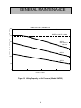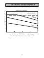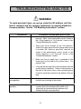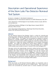
1
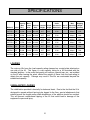
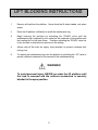
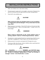
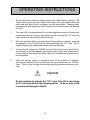
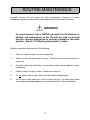
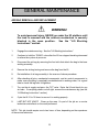
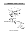
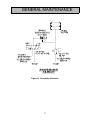
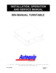
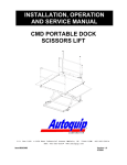
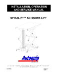
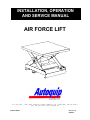
INSTALLATION, OPERATION
AND SERVICE MANUAL
AIR FORCE LIFT
P.O. Box 1058
Item # 830AFB
• 1058 West Industrial Avenue Guthrie,
•
OK 73044-1058
•
FAX: 405-282-8105 • www.autoquip.com
405-282-5200 •
Version 1.0
02/20/01
TABLE OF CONTENTS
Identification and Inspection
3
Dangers and Warnings
4
Label Identification
6
Specifications
10
Lift Blocking Instructions
11
Installation Instructions
12
Operating Instructions
13
Routine Maintenance
14
General Maintenance
15
Replacement Parts List
20
Troubleshooting Analysis
21
IMPORTANT
Please read and understand this manual prior to installation or operation of this lift.
Failure to do so could lead to property damage and/or serious personal injury. If any
questions arise, call a local representative or Autoquip Corporation at 1-888-811-9876
or 405-282-5200.
PLANNED MAINTENANCE PROGRAM
A local Autoquip representative provides a Planned Maintenance Program (PMP) for
this equipment using factory-trained personnel. Call a local representative or Autoquip
Corporation at 1-888-811-9876 or 405-282-5200 for more information.
2
IDENTIFICATION & INSPECTION
IDENTIFICATION
When ordering parts or requesting information or service on this lift, PLEASE REFER
TO THE MODEL AND SERIAL NUMBER. This information is on a nameplate attached
to the leg assembly. Replacement parts are available from a local Autoquip distributor.
INSPECTION
Immediately upon receipt of the lift, a visual inspection should be made to determine
that it has not been damaged in transit. Any damage found must be noted on the
delivery receipt. In addition to this preliminary inspection, the lift should be carefully
inspected for concealed damage. Any concealed damage found that was not noted on
the delivery receipt should be reported in writing to the delivering carrier within 48 hours.
The following is a checklist that will aid in the inspection of this lift.
1.
Examine the entire unit for any signs of mishandling.
2.
Pay special attention to the air bag and hosing.
3.
Thoroughly examine all connections, making sure they have not vibrated loose
during transit.
4.
After installation, raise and block the lift and inspect the base frame, scissors
assembly and air bag. See the “Lift Blocking Instructions” section.
3
DANGERS, WARNINGS & CAUTIONS
Read and understand this manual and all labels prior to operating or
servicing this lift. All labels are provided in accordance with ANSI
Z535.4.
DANGER!
Do not work under lift without maintenance device!
To avoid personal injury, NEVER go under the lift platform until the load is
removed and the scissors mechanism is securely blocked in the open
position. See the “Lift Blocking Instructions” section.
DANGER!
To avoid personal injury, stand clear of scissors leg mechanism while lift is
in motion.
DANGER!
Do not inflate air bags to more than 80 PSI.
4
DANGERS, WARNINGS & CAUTIONS
WARNING!
NEVER stand, sit or ride on the lift!
WARNING!
All warning and information decals should be in place as outlined in the
“Label Identification” section. If decals are missing or damaged, they
should be replaced with new ones. Contact an Autoquip representative for
replacements.
CAUTION!
When moving the lift, do not attempt to pick it up by the platform; it is
hinged and could be damaged. Pick up from under the base frame ONLY.
CAUTION!
Do not continue to activate the “UP” valve if the lift is not raising or if it has
reached the fully raised position. To do so may result in permanent
damage to the lift.
5
LABEL IDENTIFICATION
Figure 1 Label Placement Diagram
Air Force Lift Label Information
Item No.
1
2
3
4
5
6
7
8
9
Qty
2
2
2
1
1
1
1
2
2
Description
Danger – Do Not Put Hands or Feet . . .
Max. Capacity
Caution – Familiarize Yourself with Operators Manual
Do Not Inflate To More Than 80 PSI
Leg Socket
Maint. Device
Autoquip Serial Number Nameplate
Lifting Capacity vs. Air Pressure (model 24AF25)
Lifting Capacity vs. Air Pressure (model 24AF50)
6
Part No.
36430050
36405710
36401487
36401628
36400265
36400257
36401511
36405810
36405820
LABEL IDENTIFICATION
Note: Labels shown here are not actual size.
Figure 2 Label 36430050
Figure 3 Label 36405710
Figure 4 Label 36401487
Figure 5 Label 36401628
7
LABEL IDENTIFICATION
Figure 6 Label 36400265
Figure 7 Label 36400257
Figure 8 Label 36401511
8
LABEL IDENTIFICATION
LIFTING CAPACITY vs. AIR PRESSURE
3000
S
D
N
U
O
P
2500
RATED CAPACITY = 2500#
~
Y
T
I
C2000
A
P
A
C
80 PSI
(MAX. OPERATING
R
PESSURE)
G1500
N
I
T
F
I
L 1000
60 PSI
40 PSI
500
0
0
6
12
LIFTTRAVEL ~INCH
ES
18
24
Figure 9 Label 36405810
LIFTINGCAPACITYvs. AIRPRESSURE
S 6000
D
N
U
O
P
5000
~
RATED CAPACITY = 5000#
Y
T
I
C4000
A
P
A
C
80 PSI
(MAX. OPERATING
P
RESSURE)
60 PSI
G3000
N
I
T
F
I
L 2000
40 PSI
1000
0
0
6
12
LIFT TRAVEL ~INCHES
Figure 10 Label 36405820
9
18
24
SPECIFICATIONS
Model #
Capacity Base
Frame
(Max
Size
Lbs.)
Travel
Shipping
Max.
Under
Platform Lowered Raised clearance for No. Of Operating Weight
Sizes
Height Height Pallet Jack Airbags Pressure (pounds)
24AF25-1
24”
2,500
36 x 48” 36 x 48”
9.5”
33.5”
3.38
1
80 psi
820
24AF25-2
24”
2,500
36 x 48” 48 X 48”
9.5”
33.5”
3.38
1
80 psi
860
24AF25-3
24”
2,500
36 x 48” 48 X 54”
9.5”
33.5”
3.38
1
80 psi
880
24AF25-4
24”
2,500
36 x 48” 48 X 60”
9.5”
33.5”
3.38
1
80 psi
900
24AF50-1
24”
5,000
36 x 48” 48 X 48”
9.5”
33.5”
3.38
2
80 psi
880
24AF50-2
24”
5,000
36 x 48” 48 X 54”
9.5”
33.5”
3.38
2
80 psi
900
24AF50-3
24”
5,000
36 x 48” 48 X 60”
9.5”
33.5”
3.38
2
80 psi
920
LOADING
The scissors lifts have the load capacity rating stamped on a metal plate attached on
one side of the lift. This figure is a net capacity rating for a lift furnished with the
standard platform. In the event that gravity-roll sections, special tops, etc., are installed
on the lift after leaving the plant, deduct the weight of these from the load rating to
obtain the net capacity. Damage may result if the lifts are overloaded beyond the
established capacity
UNBALANCED LOADING
The stabilization provided is basically for balanced loads. Due to the fact that the lift is
designed to operate without having to be lagged to the floor, special attachments that
extend beyond the length and/or width dimensions of the platform should be avoided.
This will prevent unintentional tipping of the lift that could lead to damage of the
equipment or personal injury.
10
LIFT BLOCKING INSTRUCTIONS
1.
Remove all load from the platform. Never block the lift when loaded, only when
empty.
2.
Raise the lift platform sufficiently to install the maintenance leg.
3.
Begin lowering the platform by activating the “DOWN” valve until the
maintenance leg is captured by the socket on the underside of the platform and
the locating disc on the base frame. Continue activating the “DOWN” valve five
to ten seconds to relieve the air pressure in the air bag.
4.
Always shut off the main air supply, when blocked, to prevent someone from
turning it on.
5.
To remove the maintenance leg, raise the platform by activating the “UP” valve to
provide sufficient clearance for the removal of the maintenance leg.
WARNING!
To avoid personal injury, NEVER go under the lift platform until
the load is removed and the scissors mechanism is securely
blocked in the open position.
11
INSTALLATION INSTRUCTIONS
1.
Make sure installation area is clean before starting.
2.
If the permanent air supply work is not complete, some means of temporary lines
with an on-off device for the air supply should be set up for testing purposes.
3.
Place the lift in the installation area.
CAUTION!
When moving the lift do not attempt to pick it up by the platform;
it is hinged and could be damaged. Pick up from under the base
frame ONLY.
4.
Make temporary air connections. Raise the lift to the top of its travel and make
positioning adjustments. Check for the proper height. If needed, shim to the
desired height.
WARNING!
Block scissors mechanism in the raised position prior to
working under lift. See the “Lift Blocking Instructions” section.
5.
If the decision is made to lag the lift to the floor, the base frame of the lift has predrilled holes for lagging the lift. Mark the holes, drill, and install with anchors.
6.
Make permanent air connections and operate the lift through a few cycles.
7.
Clean up any debris from the area. A clean installation makes a good impression
and creates a much safer environment!
WARNING!
All
DANGER,
WARNING, and CAUTION labels
and informational decals and plates must be intact and in place on the
lift. Contact an Autoquip representative if labels are missing or
damaged. See the “Label Identification” section.
12
OPERATING INSTRUCTIONS
1.
Scissors lifts have a maximum lifting capacity (see “Specifications” section). The
safety relief air valve has been factory set to open at a point slightly above the
rated load and allows the air to bypass into the atmosphere. Lowering loads
exceeding the rated capacity of the lift may result in excessive wear and damage
to the lift.
2.
This type of lift is designed primarily for in-plant applications and is furnished with
constant pressure foot valve or hand valve controls. Actuating the "UP" valve will
cause air to enter the air bag and the lift will rise.
3.
When the desired height or upward travel of the platform is attained, removing
the operators’ foot or hand from the valve deactivates the “UP” valve. The air
stops flowing into the bag and the upward movement will stop.
4.
To lower the lift, activate the "DOWN" portion of the control valve, which allows
air to exhaust to the atmosphere. Opening the down control valve allows the air
in the air bag to flow through the down valve at a controlled rate and exhaust to
the atmosphere.
5.
When the desired height or downward travel of the platform is attained,
removing the operator’s foot or hand from the valve deactivates the “DOWN”
valve. The air stops flowing from the bag and the downward movement will
stop.
CAUTION!
Do not continue to activate the "UP" valve if the lift is not raising
or if it has reached the fully raised position. To do so may result
in permanent damage to the lift.
13
ROUTINE MAINTENANCE
Normally scissors lifts will require very little maintenance. However, a routine
maintenance program could prevent costly replacement of parts and/or downtime.
WARNING!
To avoid personal injury, NEVER go under the lift platform or
perform any maintenance on the lift until the load is removed
and the scissors mechanism is securely blocked in the open
position. See the "Lift Blocking Instructions" section.
Monthly inspection should consist of the following:
1.
Check for visible air leaks; correct as necessary.
2.
Check any unusual noise when it occurs. Determine the source and correct as
necessary.
3.
Check the snap rings at all rollers, if not in place, and/or secure, replace or repair
immediately.
4.
Check all rollers for signs of wear. Replace as necessary.
5.
Do not grease roller or axles; they have lifetime-lubricated bearings.
6.
The lift has a safety relief valve, which is factory pre-set. The relief valve should
not be adjusted for any reason as it could cause the lift to fall uncontrollably.
14
GENERAL MAINTENANCE
AIR BAG REMOVAL AND REPLACEMENT
WARNING!
To avoid personal injury, NEVER go under the lift platform until
the load is removed and the scissors mechanism is securely
blocked in the open position.
See the "Lift Blocking
Instructions" section.
1.
Engage the maintenance leg. See the "Lift Blocking Instructions”.
2.
Continue to hold the “DOWN” valve after the lift has stopped traveling downward
to relieve the system air pressure.
3.
Disconnect the air bag by removing the four bolts that attach the bag to the base
and leg assembly.
4.
Remove the air bag hosing and remove the bag from the lift.
5.
Re-installation of air bag assembly is the reverse of above procedure.
6.
After checking all pins, mechanical components, and air control components to
make sure everything is completely assembled and in working order, it is a good
idea to check the lag bolts for tightness.
7.
Turn on the air supply and press the "UP" valve. Raise the lift and check for any
air leaks. If everything checks out all right, remove the maintenance leg (see the
“Lift Blocking Instructions” section).
8.
Cycle the lift 10 to 15 times to ensure it is working properly.
9.
LAST BUT NOT LEAST! Clean up the area. It’s part of the job as a service
technician and reflects on the work performed.
NOTE: This job should require one to two hours of time, depending on the experience
of the service technician.
15
GENERAL MAINTENANCE
Figure 11 Foot Valve Connections
16
GENERAL MAINTENANCE
Figure 12 Pneumatic Schematic
17
GENERAL MAINTENANCE
LIFTING CAPACITY vs. AIR PRESSURE
3000
S
D
N
U
O
P
2500
RATED CAPACITY = 2500#
~
Y
T
I
C 2000
A
P
A
C
80 PSI
(MAX. OPERATING
PRESSURE)
G1500
N
I
T
F
I
L 1000
60 PSI
40 PSI
500
0
0
6
12
LIFTTRAVEL ~INCHES
18
Figure 13 Lifting Capacity vs. Air Pressure (Model 24AF25)
18
24
GENERAL MAINTENANCE
LIFTING CAPACITY vs. AIR PRESSURE
S 6000
D
N
U
O
P
5000
~
RATED CAPACITY = 5000#
Y
T
I
C4000
A
P
A
C
80 PSI
(MAX. OPERATING
PRESSURE)
60 PSI
G3000
N
I
T
F
I
L 2000
40 PSI
1000
0
0
6
12
LIFTTRAVEL ~INCHES
18
Figure 14 Lifting Capacity vs. Air Pressure (Model 24AF50)
19
24
REPLACEMENT PARTS LIST
Part Number
40730750
41401159
41401600
41701368
47900006
52504781
52504790
52601590
Description
Airbag Actuator
3-way, 3-position _” air valve, foot operated
Foot Guard
Relief Valve; 50-200 PSI
Breather Plug, _” hex
Clevis Pin, 7/8” x 1_”
Roller Axle Pin, 1 1/8”
Roller Assembly with Bushing
20
TROUBLESHOOTING ANALYSIS
WARNING!
To avoid personal injury, NEVER go under the lift platform until the
load is removed and the scissors mechanism is securely blocked in
the open position. See the "Lift Blocking Instructions" section.
PROBLEM
Lift does not raise
POSSIBLE CAUSE AND SOLUTION
• The load may exceed the rating for the specific line
pressure. Refer to the performance curves shown in
the “Lifting Capacity vs. Air Pressure” curves in the
“General Maintenance” section.
• There may not be enough, or any, line pressure.
Check the supply pressure with a gauge and ensure
it provides the minimum pressures required as
shown in the performance curves shown in the
“Lifting Capacity vs. Air Pressure” curves in the
“General Maintenance” section.
• Make sure the air supply line is connected to the
correct port on the hand or foot control valve. It is
marked “Inlet”.
• It may be that an obstruction was introduced into the
system during installation. Check for obstructions at
the inlet of the control valve, in the connecting hose
to the lift, and at the restrictor in the bottom of the air
bag.
Lift drifts down slowly during
non-operation.
• Make sure all of the connections are tight and that
no leaks are occurring in the system.
Lift seems bouncy during
operation.
• This is normal for large volume (air bag) air-powered
systems due to the compressible nature of air,
(especially at raised elevations) between fully
lowered and fully raised positions.
21
TROUBLESHOOTING ANALYSIS
PROBLEM
Lift raises very slowly.
POSSIBLE CAUSE AND SOLUTION
• The primary cause of slow actuation in airpowered systems is a lack of air volume (cubic
feet per minute (CFM) to the lift. Determine the
air volume of the air supply system/ compressor.
For the lift to operate at reasonable speeds (2030 seconds raising time), the lift needs to have a
minimum of five CFM.
• Make sure all connections are tight and that no
leaks are occurring in the system.
• It may be that an obstruction was introduced into
the system during installation. Check for
obstructions at the inlet of the control valve, in
the connecting hose to the lift, and at the
restrictor in the bottom of the air bag.
Lift does not lower, or lowers
very slowly.
• Make sure the inlet, outlet, and exhaust lines are
connected to the correct ports on the hand or
foot control valve.
• It may be that an obstruction was introduced into
the system during installation. Check for
obstructions at the outlet of the control valve, in
the exhaust line from the control valve (if
applicable), or in the connecting hose to the lift.
• Make sure the if the lift was raised and blocked
open for maintenance that the flip-over
maintenance locks were removed from the path
of the lift rollers and placed back in the “home”
position.
22