1
1ST PRINTING JAN 01
U/R Type
Owner’s Manual
SEGA ENTERPRISES, INC. USA
MANUAL NO. 420-6602-01
Warranty
Your new Sega Product is covered for a period of 90 days from the date of shipment. This certifies
that the Printed Circuit Boards, Power Supplies and Monitor are to be free of defects in workmanship or materials under normal operating conditions. This also certifies that all Interactive Control
Assemblies are to be free from defects in workmanship and materials under normal operating conditions. No other product in this machine is hereby covered.
Sellers sole liability in the event a warranted part described above fails shall be, at its option, to
replace or repair the defective part during the warranty period. For Warranty claims, contact your
Sega Distributor.
Should the Seller determine, by inspection that the product was caused by Accident, Misuse, Neglect, Alteration, Improper Repair, Installation or Testing, the warranty offered will be null and void.
Under no circumstances is the Seller responsible for any loss of profits, loss of use, or other damages.
This shall be the exclusive written Warranty of the original purchaser expressed in lieu of all other
warranties expressed or implied. Under no circumstance shall it extend beyond the period of time
listed above.
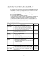
BEFORE USING THE PRODUCT, BE SURE TO READ THE FOLLOWING:
To maintain the safety:
To ensure the safe usage of the product, be sure to read the following before using the product. The following
instructions are intended for the users, operators and the personnel in charge of the operation of the product.
After carefully reading and sufficiently understanding the warning displays and cautions, handle the product
appropriately. Be sure to keep this manual nearby the product or elsewhere convenient for referring to it
when necessary.
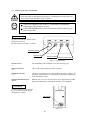
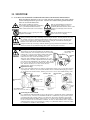
Herein, explanations which require special attention are enclosed with dual lines. Depending on the potentially hazardous degrees, the terms of WARNING, CAUTION, etc. are used. Be sure to understand the
contents of the displays before reading the text.
Indicates that mishandling the
product by disregarding this
warning will cause a potentially
hazardous situation which can
result in death or serious injury.
Indicates that mishandling the product
by disregarding this caution will cause
a slight hazardous situation which can
result in personal injury and or material
damage.
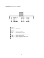
For the sage usage of the product, the following pictographs are used:
Indicates “HANDLE WITH CARE.” In order to protect the human body an equipment, this
display is attached to places where the Owner’s Manual and or Service Manual should be referred
to.
Perform work in accordance with the instructions herein stated.
Instructions for work are explained by paying attention to the aspect of accident prevention. Failing to
perform work as per the instructions can cause accidents. In the case where only those who have technical expertise should perform the work to avoid hazardous situation, the instructions herein state that the
serviceman should perform such work.
Be sure to turn off power before working on the machine.
To prevent electric shock, be sure to turn off power before starting the work in which the worker touches
the interior of the product. If the work is to be performed in the power-on status, the Instruction Manual
herein always states to that effect.
Be sure to ground the Earth Terminal (this, however, is not required in the case where a power cord
with earth is used).
This product is equipped with the Earth Terminal. When installing the product, Connect the Earth Terminal to the “accurately grounded indoor earth terminal” by using an earth wire. Unless the product is
grounded appropriately, the user can be subject to electric shock. After performing repair, etc. for the
Control equipment, ensure that the Earth Wire is firmly connected to the Control equipment.
Ensure that the Power Supply used is equipped with an Earth Leakage Breaker.
This product does not incorporate the Earth Leakage Breaker. Using a power supply which is not
equipped with the Earth Leakage Breaker can cause a fire when earth leakage occurs.
Be sure to use fuses which meet the specified rating. (only for the machines which use fuses).
Using fuses exceeding the specified rating can cause a fire and electric shock.
Specification changes (removal of equipment, conversion and addition) not designated by SEGA
are not allowed.
The parts of the product include warning labels for safety, covers for personal protection, etc. It is very
hazardous to operate the product by removing parts and or modifying the circuits. Should doors, lids
and protective parts be damaged or lost, refrain from operating the product, and contact where the
product was purchased from or the office herein stated. SEGA shall not be held responsible for any
accidents, compensation for damage to a third party, resulting from the specifications not designated by
SEGA.
Ensure that the product meets the requirements of appropriate Electrical Specifications.
Before installing the product, check for Electrical Specifications. SEGA products have a nameplate on
which Electrical Specifications are described. Ensure that the product is compatible with the power
supply voltage and frequency requirements of the location. Using any Electrical Specifications different
from the designated Specifications can cause a fire and electric shock.
Install and operate the product in places where appropriate lighting is available, allowing warning
labels to be clearly read.
To ensure safety for the customers, labels and printed instructions describing potentially hazardous
situation are applied to places where accidents can be caused. Ensure that where the product is operated
has sufficient lighting allowing the warnings to be read. If any label is peeled off, apply it again immediately. Please place an order with where the product was purchased from or the office herein stated.
When handling the Monitor, be very careful. (Applies only to the product w/monitor.)
Some of the monitor (TV) parts are subject to high tension voltage. Even after running off power, some
portions are still subject to high tension voltage sometimes. Monitor repair and replacement should be
performed only be those technical personnel who have knowledge of electricity and technical expertise.
Be sure to adjust the monitor (projector) properly. (Applies only to the product w/monitor.)
Do not operate the product leaving on-screen flickering or blurring as it is. Using the product with the
monitor not properly adjusted may cause dizziness or a headache to an operator, a player, or the customers.
When transporting or reselling this product, be sure to attach this manual to the product.
In the case where commercially available monitors and printers are used in this product, only the
contents relating to this product are explained herein. Some commercially available equipment has
functions and reactions not stated in this manual. Read this manual together with the specific Instruction Manual of such equipment.
• Descriptions herein contained may be subject to improvement changes without notice.
• The contents described herein are fully prepared with due care. However, should any question arise or
errors be found, please contact SEGA.
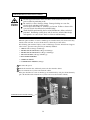
INSPECTIONS IMMEDIATELY AFTER TRANSPORTING THE PRODUCT TO THE LOCATION.
Normally, at the time of shipment, SEGA products are in a status allowing for usage immediately after
transporting to the location. Nevertheless, an irregular situation may occur during transportation. Before
turning on power, check the following points to ensure that the product has been transported in a satisfactory status.
Are there any dented portions or defects (cuts, etc.) on the external surfaces of the cabinet?
Are Casters and Adjusters, damaged?
Do the power supply voltage and frequency requirements meet with those of the location?
Are all wiring connectors correctly and securely connected? Unless connected in the correct direction,
connector connections can not be made accurately. Do not insert connectors forcibly.
Do power cords have cuts and dents?
Do the fuses used meet specified rating? Is the Circuit Protector in an energized status?
Are all accessories available?
Can all Doors and Lids be opened with the Accessory keys? Can Doors and Lids be firmly closed?
TABLE OF CONTENTS
BEFORE USING THE PRODUCT, BE SURE TO READ THE FOLLOWING:
TABLE OF CONTENTS
INTRODUCTION OF THE OWNER'S MANUAL
1. HANDLING PRECAUTIONS ......................................................................... 1
2. PRECAUTIONS CONCERNING INSTALLATION LOCATION................. 2 - 3
3. OPERATION .................................................................................................... 4 - 6
4. NAME OF PARTS ............................................................................................ 7
5. ACCESSORIES ................................................................................................ 8 - 12
6. ASSEMBLING AND INSTALLATION .......................................................... 13 - 28
7. PRECAUTIONS TO BE HEEDED WHEN MOVING THE MACHINE ........ 29
8. CONTENTS OF GAME ................................................................................... 30 - 38
9. EXPLANATION OF TEST AND DATA DISPLAY ...................................... 39 - 49
9 - 1 SWITCH UNIT AND COIN METER .................................................. 40
9 - 2 SYSTEM TEST MODE ....................................................................... 41
9 - 3 GAME TEST MODE ........................................................................... 42 - 49
10. CONTROLLER ................................................................................................ 50 - 51
11. MONITOR.... .................................................................................................... 52 - 56
11 - 1 CAUTIONS AND WARNINGS CONCERNING
THE SAFETY FOR HANDLING THE MONITORS .......................... 52 - 54
11 - 2 CAUTIONS TO BE HEEDED WHEN CLEANING THE CRT
SURFACES ........................................................................................... 54
11 - 3 ADJUSTMENT METHOD .................................................................. 55 - 56
12. COIN SELECTOR ............................................................................................ 57
13. REPLACING THE FLUORESCENT LAMP, AND LAMPS .......................... 58 - 59
14. PERIODIC INSPECTION TABLE ................................................................... 60 - 61
15. TROUBLESHOOTING .................................................................................... 62 - 64
16. GAME BOARD ................................................................................................ 65 - 69
16 - 1 REMOVING THE GAME BOARD .................................................... 65 - 68
16 - 2 COMPOSITION OF GAME BOARD ................................................. 69
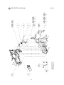
17. DESIGN RELATED PARTS ............................................................................ 70
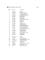
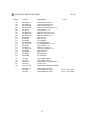
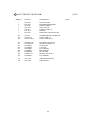
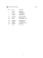
18. PARTS LIST ..................................................................................................... 71 - 101
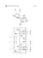
19. WIRE COLOR CODE TABLE ........................................................................ 102
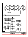
20. WIRING DIAGRAM ........................................................................................ 103 - 104
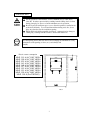
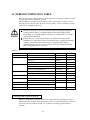
SPECIFICATIONS
Installation space
Height
Weight
Power, maximum current
For TAIWAN
Power, current
MONITOR
: 800 mm (W) X 997 mm (D)
(31.5 in. X 39.3 in.)
: 2,044 mm (80.5 in.)
: Approx. 180 kg. (396.8 lbs.)
: 285 W 3.32 A (AC 110V 50 Hz AREA)
280 W 3.20 A (AC 110V 60 Hz AREA)
280 W 2.95 A (AC 120V 60 Hz AREA)
290 W 1.63 A (AC 220V 50 Hz AREA)
290 W 1.60 A (AC 220V 60 Hz AREA)
285 W 1.57 A (AC 230V 50 Hz AREA)
285 W 1.55 A (AC 230V 60 Hz AREA)
290 W 1.51 A (AC 240V 50 Hz AREA)
295 W 1.50 A (AC 240V 60 Hz AREA)
: 278 W 3.20A (MAX.)
170 W 1.96A (MIN.)
: 29 TYPE COLOR MONITOR
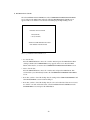
INTRODUCTION OF THE OWNER'S MANUAL
This Owner's Manual is intended to provide detailed descriptions together with all
the necessary information covering the general operation of electronic assemblies,
electromechanicals, servicing control, spare parts, etc. as regards the product,
CONFIDENTIAL MISSION U/R TYPE.
This manual is intended for the owners, personnel and managers in charge of
operation of the product. Operate the product after carefully reading and sufficiently
understanding the instructions. If the product fails to function satisfactorily, nontechnical personnel should under no circumstances touch the internal system. Please
contact where the product was purchased from.
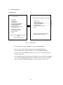
Use of this product is unlikely to cause physical injuries or damages to property. However,
where special attention is required this is indicated by a thick line, the word "IMPORTANT"
and its sign in this manual.
STOP
Indicates that mishandling the product by disregarding this display can cause the
product's intrinsic performance not to be obtained, resulting in malfunctioning.
IMPORTANT
SEGA ENTERPRISES, INC. (U.S.A.)/CUSTOMER SERVICE
45133 Industrial Drive, Fremont, California 94538, U.S.A.
Phone : (415) 701-6580
Fax : (415) 701-6594
DEFINITION OF LOCATION MAINTENANCE MAN AND SERVICEMAN
Non-technical personnel who do not have technical knowledge and expertise should
refrain from performing such work that this manual requires the location's
maintenance man or a serviceman to carry out, or work which is not explained in
this manual. Failing to comply with this instruction can cause a severe accident
such as electric shock.
Ensure that parts replacement, servicing & inspections, and troubleshooting are performed by the
location's maintenance man or the serviceman. It is instructed herein that particularly hazardous
work should be performed by the serviceman who has technical expertise and knowledge.
The location's maintenance man and serviceman are herein defined as follows:
"Location's Maintenance Man" :
Those who have experience in the maintenance of amusement equipment and vending machines,
etc., and also participate in the servicing and control of the equipment through such routine work
as equipment assembly and installation, servicing and inspections, replacement of units and
consumables, etc. within the Amusement Facilities and or locations under the management of the
Owner and Owner's Operators of the product.
Activities of Location's Maintenance Man :
Assembly & installation, servicing & inspections, and replacement of units & consumables as
regards amusement equipment, vending machines, etc.
Serviceman :
Those who participate in the designing, manufacturing, inspections and maintenance service of
the equipment at an amusement equipment manufacturer.
Those who have technical expertise equivalent to that of technical high school graduates as regards electricity, electronics and or mechanical engineering, and daily take part in the servicing &
control and repair of amusement equipment.
Serviceman's Activities :
Assembly & installation and repair & adjustments of electrical, electronic and mechanical parts of
amusement equipment and vending machines.
1. HANDLING PRECAUTIONS
When installing or inspecting the machine, be very careful of the following points and pay
attention to ensure that the player can enjoy the game safely.
Non-compliance with the following points or inappropriate handling running counter to the
cautionary matters herein stated can cause personal injury or damage to the machine.
Before performing work, be sure to turn power off. Performing the work
without turning power off can cause an electric shock or short circuit. In the
case work should be performed in the status of power on, this manual always
states to that effect.
To avoid electric shock or short circuit, do not plug in or unplug quickly.
To avoid electric shock, do not plug in or unplug with a wet hand.
Do not expose Power Cords and Earth Wires on the surface, (floor, passage,
etc.). If exposed, the Power Cords and Earth Wires are susceptible to damage.
Damaged cords and wires can cause electric shock or short circuit.
To avoid causing a fire or electric shock, do not put things on or damage
Power Cords.
When or after installing the product, do not unnecessarily pull the power cord.
If damaged, the power cord can cause a fire or electric shock.
In case the power cord is damaged, ask for replacement through where the
product was purchased from or the office herein stated. Using the cord as is
damaged can cause fire, electric shock or leakage.
Be sure to perform grounding appropriately. Inappropriate grounding can
cause an electric shock.
Be sure to use fuses meeting specified rating. Using fuses exceeding the
specified rating can cause a fire or electric shock.
Completely make connector connections for IC BD and others. Insufficient
insertion can cause an electric shock.
Specification changes, removal of equipment, conversion and/or addition, not
designated by SEGA are not permitted.
• Failure to observe this may cause a fire or an electric shock. Non-compliance
with this instruction can have a bad influence upon physical conditions of the
players or the lookers-on, or result in injury during play.
• SEGA shall not be held responsible for damage, compensation for damage to
a third party, caused by specification changes not designated by SEGA.
Be sure to perform periodic maintenance inspections herein stated.
STOP
IMPORTANT
For the IC board circuit inspections, only the logic tester is allowed. The use
of a multiple-purpose tester is not permitted, so be careful in this regard.
When cleaning the CRT surfaces, use a soft, dry cloth. Do not apply
chemicals such as thinner, benzine, etc.
The electronic parts on the IC Board could be damaged due to human body's
static electricity. Before performing IC Board related work, be sure to
discharge physically accumulated statics by touching grounded metallic
surfaces, etc.
1
2. PRECAUTIONS CONCERNING INSTALLATION
LOCATION
This product is an indoor game machine. Do not install it outside. Even indoors,
avoid installing in places mentioned below so as not to cause a fire, electric shock,
injury and or malfunctioning.
Places subject to rain or water leakage, or places subject to high humidity in
the proximity of an indoor swimming pool and or shower, etc.
Places subject to direct sunlight, or places subject to high temperatures in the
proximity of heating units, etc.
Places filled with inflammable gas or vicinity of highly inflammable/volatile
chemicals or hazardous matter.
Dusty places.
Sloped surfaces.
Places subject to any type of violent impact.
Vicinity of anti-disaster facilities such as fire exits and fire extinguishers.
The operating (ambient) temperature range is from 5 Celsius to 40 Celsius.
Only in the case a projector is employed, the temperature range is from 5
Celsius to 30 Celsius.
LIMITATIONS OF USAGE REQUIREMENTS
Be sure to check the Electrical Specifications.
Ensure that this product is compatible with the location's power supply,
voltage and frequency requirements.
A plate describing Electrical Specifications is attached to the product.
Non-compliance with the Electrical Specifications can cause a fire and
electric shock.
This product requires the Breaker and Earth Mechanisms as part of the
location facilities. Using them in a manner not independent can cause a fire
and electric shock.
Ensure that the indoor wiring for the power supply is rated at 7A or higher
(AC single phase 100 ~ 120V area), and 7A or higher (AC 220 ~ 240V area).
Non-compliance with the Electrical Specifications can cause a fire and
electric shock.
Be sure to independently use the power supply equipped with the Earth
Leakage Breaker. Using a power supply without the Earth Leakage Breaker
can cause an outbreak of fire when earth leakage occurs.
Putting many loads on one electrical outlet can cause generation of heat and a
fire
resulting from overload.
When using an extension cord, ensure that the cord is rated at 7A or higher
(AC 100 ~ 120V area) and 7A or higher (AC 220 ~ 240V area). Using a cord
rated lower than the specified rating can cause a fire and electric shock.
2
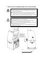
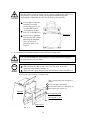
OPERATION AREA
For the operation of this machine, secure a minimum area of 1.4m (W) X
1.8m (D). In order to prevent injury resulting from the falling down accident
during game play, be sure to secure the minimum area for operation.
Be sure to provide sufficient space so as to allow this product's ventilation fan
to function efficiently. To avoid machine malfunctioning and a fire, do not
place any obstacles near the ventilation opening.
SEGA shall not be held responsible for damage, compensation for damage to
a third party, resulting from the failure to observe this instruction.
STOP
IMPORTANT
For transporting the machine into the location's building, the minimum necessary
dimensions of the opening (of doors, etc.) are 0.9m(W) and
2m(H).
Electric current consumption
MAX. 3.32 A (AC 110V 50 Hz)
MAX. 3.20 A (AC 110V 60 Hz)
MAX. 2.95 A (AC 120V 60 Hz)
MAX. 1.63 A (AC 220V 50 Hz)
MAX. 1.60 A (AC 220V 60 Hz)
MAX. 1.57 A (AC 230V 50 Hz)
MAX. 1.55 A (AC 230V 60 Hz)
MAX. 1.51 A (AC 240V 50 Hz)
MAX. 1.50 A (AC 240V 60 Hz)
MAX. 3.20 A (For TAIWAN)
FIG. 2
3
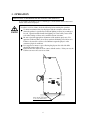
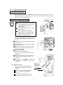
3. OPERATION
PRECAUTIONS TO BE HEEDED BEFORE STARTING THE OPERATION
To avoid injury and trouble, be sure to constantly give careful attention to the behavior and
manner of the visitors and players.
In order to avoid accidents, check the following before starting the operation:
To ensure maximum safety for the players and the customers, ensure that
where the product is operated has sufficient lighting to allow any warnings to
be read. Operation under insufficient lighting can cause bodily contact with
each other, hitting accident, and or trouble between customers.
Be sure to perform appropriate adjustment of the monitor (projector). For
operation of this machine, do not leave monitor's flickering or deviation as is.
Failure to observe this can have a bad influence upon the players' or the
customers' physical conditions.
It is suggested to ensure a space allowing the players who feel sick while
playing the game to take a rest.
Check if all of the adjusters are in contact with the surface. If they are not, the
Cabinet can move and cause an accident.
Ensure that all of the Adjusters
are in contact with the floor.
4
Do not put any heavy item on this product. Placing any heavy item on the
product can cause a falling down accident or parts damage.
Do not climb on the product. Climbing on the product can cause falling down
accidents. To check the top portion of the product, use a step.
To avoid electric shock, check to see if door & cover parts are damaged or
omitted.
To avoid electric shock, short circuit and or parts damage, do not put the
following items on or in the periphery of the product.
Flower vases, flowerpots, cups, water tanks, cosmetics, and receptacles/
containers/vessels containing chemicals and water.
To avoid injury, be sure to provide sufficient space by considering the potentially
crowded situation at the installation location. Insufficient installation space can
cause making bodily contact with each other, hitting accidents, and or trouble
between customers.
STOP
Players with bare hands directly hold the maracas. For operation, it is
recommended that the wet towels (paper towels) be provided.
IMPORTANT
5
PRECAUTIONS TO BE HEEDED DURING OPERATION (PAYING ATTENTION TO CUSTOMERS)
To avoid injury and trouble, be sure to constantly give careful attention to the behavior and
manner of the visitors and players.
To avoid injury and accidents, those who fall under the following categories
are not allowed to play the game.
• Those who need assistance such as the use of an apparatus when walking.
• Those who have high blood pressure or a heart problem.
• Those who have experienced muscle convulsion or loss of consciousness when
playing video game, etc.
• Those who have a trouble in the neck and or spinal cord.
• Intoxicated persons.
• Pregnant women or those who are in the likelihood of pregnancy.
• Persons susceptible to motion sickness.
• Persons whose act runs counter to the product's warning displays.
A player who has never been adversely affected by light stimulus might
experience dizziness or headache depending on his physical condition when
playing the game. Especially, small children can be subject to those
conditions. Caution guardians of small children to keep watch on their
children during play.
Instruct those who feel sick during play to have a medical examination.
To avoid injury resulting from falling down and electric shock due to spilled
drinks, instruct the player not to place heavy items or drinks on the product.
To avoid electric shock and short circuit, do not allow customers to put hands
and fingers or extraneous matter in the openings of the product or small
openings in or around the doors.
To avoid falling down and injury resulting from falling down, immediately
stop the customer's leaning against or climbing on the product, etc.
To avoid electric shock and short circuit, do not allow the customers to
unplug the power plug without a justifiable reason.
Immediately stop such violent acts as hitting and kicking the product. Such
violent acts can cause parts damage or falling down, resulting in injury due to
fragments and falling down.
6
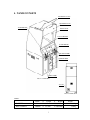
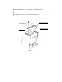
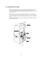
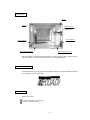
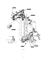
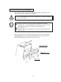
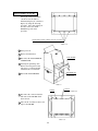
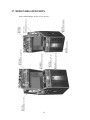
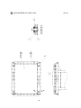
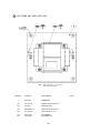
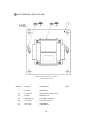
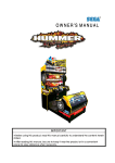
4. NAME OF PARTS
BILLBOARD PLATE R
BILLBOARD PLATE
1P CONTROLLER
FRONT GLASS
29 TYPE MONITOR
2P CONTROLLER
COIN CHUTE DOOR
CASHBOX DOOR
FRONT DOOR
FIG. 4 a OVERVIEW
AC UNIT
FIG. 4 b REAR VIEW
TABLE 4
Width
X
Length
CABINET
800 mm
X
997 mm
X 1,900mm
180 kg
When assembled
800 mm
X
997 mm
X 2,044 mm
180 kg
7
X
Height
Weight
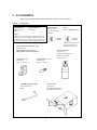
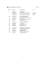
5. ACCESSORIES
When transporting the machine, make sure that the following parts are supplied.
TABLE 5 ACCESSORIES
DESCRIPTION
Part No. (Qty.)
Note
KEY MASTER
220-5576 (2)
For opening/closing
the doors
OWNERS MANUAL
420-6602-01 (1)
Figures
KEY (2)
For the CASHBOX DOOR
If Part No. has no description, the Number has not been
registered or can not be registered. Such a part may not
be obtainable even if the customer desires to purchase it.
Therefore, ensure that the part is in safekeeping with you.
The Keys are inside the Coin
Chute Door at the time of
shipment from the factory.
GD-ROM SERVICE MANUAL ENG
420-6620-01 (1)
INSTRUCTION MANUAL FOR
THE GAME BOARD AND GD-ROM
SW MICRO TYPE
509-5080 (1)
Spare, see Section 10.
LAMP WEDGE 6V 3W
390-5160 (1)
Spare, see Section 13.
TAMPERPROOF†WRENCH
M4 540-0006-01 (1)
TOOL
GLASS CLEANER
090-0174 (1)
Used for cleaning the Front
Glass of the Projector.
See Section 14.
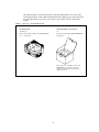
CARTON BOX
601-10532 (1)
Used for transporting the
Game Board. See FIG. 5 a.
8
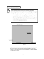
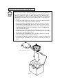
HOW TO USE THE CARTON BOX
STOP
IMPORTANT
When requesting for the replacement/repair of this product's Game Board
(NAOMI BOARD), follow the instructions below. Transporting the Game Board
in an undesignated status is unacceptable. An erroneous handling can cause parts
damage.
• Put the Game Board in the Carton Box together with the Shield Case. Do not
unnecessarily disassemble nor remove parts.
• By paying careful attention to the following Figure and the direction shown
by on-Carton-Box printing, put the Shield Case in the Carton Box.
• When putting the Shield Case in the Carton Box, do not remove Leg Brackets.
• The projected portions of the packing material is intended for cushioning.
Therefore, do not bend the projected portions.
• Do not remove the DIMM board without fail.
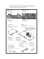
"CHECK SIDE" Display
Serial No. Display
FILTER BOARD
Projected portions of
the packing material.
Serial No. Display
FIG. 5 a
Fold the packing material in the sequential order of the numbers shown in the Figure, enfold
the Shield Case and put it in the Carton Box. Positioning the Shield Case upside down or
packing in the manner different from what is shown in this Figure can cause the Game Board
and other parts to be damaged.
9
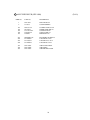
The following Table 5b lists the parts that had been separately packed when the product was
shipped from the factory but are necessary when you use the product. These parts will be
mounted on the product when installing and assembling it.
TABLE 5 b
BILLBOARD PLATE
SPY-0003 (1)
See 1 of Section 6.
BILLBOARD PLATE R
SPY-0004 (1)
See 1 of Section 6.
PLATE HOLDER
SPY-0005 (1)
See 1 of Section 6.
TAPPING SCREW
011-T03512 (2)
See 1 of Section 6.
GD-ROM
610-0625-0001 (1)
Game software media contained in a plastic case.
see 3 of Section 6.
GD DRIVE BRACKET
105-5435 (1)
To be mounted on the GD-ROM drive.
see 3 of Section 6.
FLANGE NUT
050-F00500 (4)
Used for securing the
GD-ROM DRIVE.
see 3 of Section 6.
NOTE: A packing/shipping method of this
product is specific with this CONFIDENTIAL
MISSION DX TYPE product. It may be
different from, therefore, the descriptions in
the GD-ROM Service Manual.
TAPPING SCREW
012-P00408 (4)
Used for securing the
GD-ROM DRIVE.
see 3 of Section 6.
AC Cable (Power Cord)
600-6729 (1) TAIWAN
600-6618 (1) OTHERS
600-6619 (1) HONG KONG
Used for installation, see 4 of Section 6.
WIRE HARN EARTH W/LUG M6
600-6664-02 (1)
For TAIWAN.
Used for installation,
see 4 of Section 6.
10
CORD CLAMP
280-5009-01 (1)
Used for securing the
power cord.
see 4 of Section 6.
The following Table 5c lists the parts that are separately marketed but are necessary when
booting this product's software. When having unpacked the shipping crate, make sure that all
the parts in this Table 5C are in the crate. If not so, contact where you have obtained the
product.
TABLE 5 c (XKT-0833 : GD-ROM DRIVE KIT)
GD-ROM DRIVE CARTON BOX
(1)
Used for transporting the GD-ROM DRIVE.
See FIG. 5 b.
GD-ROM DRIVE
610-0617 (1)
Device that loads the software in a GD-ROM disk.
see 3 of Section 6.
This carton box is a standard accessory of the
GD-ROM drive. If you want to obtain the
carton box itself separately, specify the part
number 601-11031.
11
HOW TO USE THE CARTON BOX (GD-ROM DRIVE)
STOP
IMPORTANT
When you want to order for replacing or repairing service of the GD-ROM drive
that is used by the product, pack it in a carton box as instructed below, and then
deliver the carton box to a service agent. If you do not observe the instruction,
your order may not be accepted or may be charged additionally. If you handle the
GD-ROM drive differently from the following instructions, its components may
be damaged.
• Contain the GD-ROM drive in a dedicated carton box. Do not disassemble it
or remove any part from it unless otherwise instructed.
• Before containing the GD-ROM drive in a dedicated carton box, attach the
GD-ROM drive lid (DISC LID) onto the drive and fix the lid with a screw.
• Before containing the GD-ROM drive in a dedicated carton box, remove the
GD-ROM disk from the drive. Do not attempt to move the GD-ROM drive
with a GD-ROM disk inside.
• Before containing the GD-ROM drive in a dedicated carton box, remove the
GD-ROM drive bracket. Carefully keep the GD-ROM drive bracket and the 4
set screws, because they will be reused.
• When inserting the GD-ROM drive into a dedicated carton box, be careful
about an inserting direction as illustrated below.
• The packing materials in a carton box are used as a cushion. Use them always
when inserting the GD-ROM drive into a dedicated carton box. Do not bend
them.
Remove the GD drive bracket.
FIG. 5 b
12
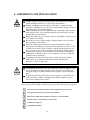
6. ASSEMBLING AND INSTALLATION
Perform assembly work by following the procedure herein stated. Failing to
comply with the instructions can cause electric shock hazard.
Perform assembling as per this manual. Since this is a complex machine,
erroneous assembling can cause an electric shock, machine damage and or not
functioning as per specified performance.
When assembling, be sure to use plural persons. Depending on the assembly
work, there are some cases in which working by one person alone can cause
personal injury or parts damage.
Ensure that connectors are accurately connected. Incomplete connections can
cause electric shock hazard.
Be careful so as not to damage wirings. Damaged wiring can cause electric
shock and short circuit hazards.
This work should be performed by the Location's Maintenance Man or
Serviceman. Performing work by non-technical personnel can cause a severe
accident such as electric shock. Failing to comply with this instruction can
cause a severe accident such as electric shock to the player during operation.
Provide sufficient space so that assembling can be performed. Performing
work in places with narrow space or low ceiling may cause an accident and
assembly work to be difficult.
To perform work safely and avoid serious accident such as the cabinet's
falling down, do not perform work in places where step-like grade
differences, a ditch, or slope exist.
When handling plastic parts, use care. Do not give a shock or apply excessive
load to the fluorescent lamps and plastic parts. Failure to observe this can
cause parts damage, resulting in injury due to fragments, cracks and broken
pieces.
To perform work safely and securely, be sure to prepare a step which is in a
secure and stable condition. Performing work without using the step can
cause violent falling down accidents.
When carrying out the assembly work, follow the procedure in the following 6-item sequence:
INSTALLATION OF BILLBOARD PLATE AND BILLBOARD PLATE R
SECURING IN PLACE (ADJUSTER ADJUSTMENT)
INSTALLING THE GD-ROM DRIVE (SETTING A GD-ROM DISK)
POWER SUPPLY, AND EARTH CONNECTION
TURNING POWER ON
ASSEMBLING CHECK
13
The master key (accessories) in addition to the tools such as a Phillips type screwdriver, Box nut
screwdriver and wrench are required for the assembly work.
24mm
Phillips type screwdriver
(for M3,M4 screw)
7mm
WRENCH (for M16 hexagon bolt)
Box nut screwdriver
(For M4 hexagon nut)
KEY MASTER
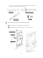
INSTALLATION OF BILLBOARD PLATE AND BILLBOARD PLATE R
1 Remove the 4 truss head screws, and thereby remove the lamp cover B.
2 Insert the billboard plate, and tighten the 4 truss head screws to fix the lamp cover B.
TRUSS SCREW(4), black
M4 X 12,flat washer used.
LAMP COVER B
BILLBOARD PLATE
FIG. 6. 1 a
When performing work,
prepare a step.
14
3 Insert the billboard plate R into a slot on the rear of the billboard case.
4 Using a both-side adhesive tape, stick the plate holder onto the rear of the billboard plate R.
5 Tighten the 2 tapping screws, and thereby fix the plate holder.
Double-sided adhesive tape
TAPPING SCREW (2)
3.5 X 12
BILLBOARD PLATE R
PLATE HOLDER
FIG 6. 1 b
15
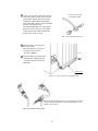
SECURING IN PLACE (ADJUSTER ADJUSTMENT)
Make sure that all of the adjusters are in contact with the floor. If they are not, the
cabinet can move and cause an accident.
This machine has 4 casters and 4 adjusters. When the installation position is determined, cause
the adjusters to come into contact with the floor directly, make adjustments in a manner so that
the casters will be raised approximately 5mm. from the floor and make sure that the machine
position is level.
1 Move the machine to the installation
position.
2 Cause all of the adjusters to make
contact with the floor. By using a
wrench, make adjustments in the
height of the adjusters to ensure that
the machine's position is level.
ADJUSTER
3 After making adjustments, fasten the
adjuster nut upward and secure the
height of the adjuster.
CASTER
FIG. 6. 2 a BOTTOM VIEW
ADJUSTER
CASTER
FASTEN UPWARD.
Approx.5mm
FIG. 6. 2 b ADJUSTER
ADJUSTER
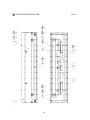
FIG. 6. 2 c
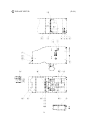
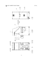
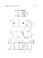
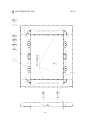
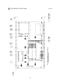
Refer to this Fig. (Scale:1/100) for
the layout of the place of installation.
FIG. 6. 2 d
Provide sufficient space so as
to allow for ventilation by the
ventilation fan.
16
INSTALLING THE GD-ROM DRIVE (SETTING A GD-ROM DISK)
STOP
IMPORTANT
Carefully handle the GD-ROM drive so as not to contaminate the disk and
the readout lens with stains and dust particles.
Do not continue to use the scratched GD-ROM disk. The scratched GD-ROM
disk may cause the system to malfunction.
Set the GD-ROM disk onto the GD-ROM drive with its labeled side facing
upward.
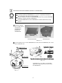
1 Unpack the shipping
crate, and take out the
GD-ROM drive,
GD-ROM drive
bracket, and
GD-ROM disk.
GD-ROM DRIVE
GD DRIVE BRACKET
PHOTO 6. 3 a
2 Use the 4 tapping screws to fix the GD-ROM drive bracket onto the GD-ROM drive. Be careful
about a fixing direction.
TAPPING SCREW (4)
4X8
GD DRIVE BRACKET
FIG. 6. 4 b
GD-ROM DRIVE
CAUTION for U. S. A., Europe, and Australia:
Attach the 2 caution stickers for a laser ray onto
the GD-ROM drive.
FIG. 6. 3 a
17
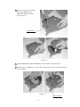
3 Remove the 1 truss head screw that
fixes the GD-ROM drive lid
(DISC LID). And turn clockwise
the lid to remove.
TRUSS SCREW (1)
M3 X 8
PHOTO 6. 3 b
4 Set the GD-ROM disk onto the GD-ROM drive with its labeled side facing upward.
5 Return the lid to its original place, and fix it with 1 truss head screw. Be careful not to fasten the
screw too tightly.
PHOTO 6. 3 c
TRUSS SCREW (1)
M3 X 8
18
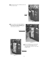
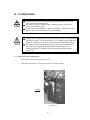
6 Unlock the front-left door, and thereby remove the
door from the cabinet.
UNLOCK
PHOTO 6. 3 d
7 Now you will take out the ASSY MAIN BD from
the cabinet and mount the GD-ROM drive onto it.
First, remove the 7 connectors from the upper
section of the rear of the door.
Disconnect the connector.
PHOTO 6. 3 e
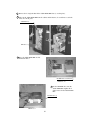
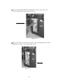
8 Remove the D-SUB connector from the filter
board (a part of the NAOMI board on the
ASSY MAIN BD). Unclamp the cable with the
D-SUB connector.
D-SUB connector
PHOTO 6. 3 f
19
9 Remove the 2 wing bolts that fix the ASSY MAIN BD's base (a wooden plate).
10 Take out the ASSY MAIN BD from the cabinet. In this instance, be careful not to catch the
wires on or in the parts.
WING BOLT (2)
M4 X 30,flat washer used
PHOTO 6. 3 g
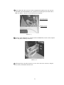
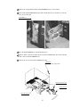
11 Place the ASSY MAIN BD on a flat
horizontal surface.
GD-ROM drive is installed here.
PHOTO 6. 3 h
12 Set the GD-ROM drive onto the
ASSY MAIN BD. Tighten the 4
flange nuts to fix the ASSY MAIN
BD.
FLANGE NUT (4)
M4
PHOTO 6. 3 i
20
13 Insert both the GD cable connector (for data communication) and the power cord connector
(JST NH6P) into the GD-ROM drive. Be careful about an inserting direction in this instance.
Make sure that the connectors are inserted firmly and completely.
Power Cord connector
GD Cable connector
PHOTO 6. 3 j
14 Return the ASSY MAIN BD (now installed with the GD-ROM drive) into the cabinet. Tighten
the 2 wing bolts, and thereby fix the base.
PHOTO 6. 3 k
15 Following the above-described actions in a reverse order, connect the connectors, clamp the
wires/cables, and install the front-left door.
21
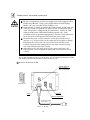
POWER SUPPLY, AND EARTH CONNECTION
Be sure to independently use the power supply socket outlet equipped with an
Earth Leakage Breaker. Using a power supply without an Earth Leakage
Breaker can cause a fire when electric leakage occurs.
Ensure that the "accurately grounded indoor earth terminal" and the earth wire
cable are available (except in the case where a power cord plug with earth is
used). This product is equipped with the earth terminal. Connect the earth
terminal and the indoor earth terminal with the prepared cable. If the
grounding work is not performed appropriately, customers can be subjected to
an electric shock, and the product's functioning may not be stable.
Ensure that the power cord and earth wire are not exposed on the surface
(passage, etc.). If exposed, they can be caught and are susceptible to damage.
If damaged, the cord and wire can cause electric shock and short circuit
accidents. Ensure that the wiring position is not in the customer's passage
way or the wiring has protective covering.
After wiring power cord on the floor, be sure to protect the power cord.
Exposed power cord is susceptible to damage and causes an electric shock
accident.
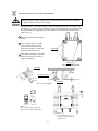
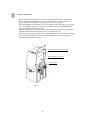
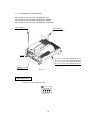
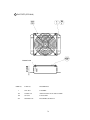
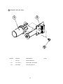
The AC Unit is mounted on the rear of the machine. The AC Unit has Circuit Protector, Main
SW, Earth Terminal and the Inlet which connects the Power Cord.
1 Ensure that the Main SW is OFF.
EARTH TERMINAL
Connect with the
indoor earth terminal.
Main SW off
MAIN SW
INLET
CIRCUIT PROTECTOR
To the Power Supply
Socket outlet
FIG. 6. 4 a AC unit
22
2 Connect one end of the earth wire to the AC
Unit earth terminal, and the other end to the
indoor earth terminal. The AC Unit earth
terminal has a Bolt and Nut combination.
Take off the Nut, pass the earth wire through
the Bolt, and fasten the Nut.
Note that the Earth Wire is incorporated in
the Power Cord for the Areas of AC 120V
(USA) and AC 220 ~ 240V, and therefore,
this procedure is not necessary.
Connect the Earth Wire
to the Earth Terminal.
FIG. 6. 4 b Earth Wire Connection
3 Firmly insert the power plug into
the socket outlet.
Insert the opposite side of Power
Cord plug to the AC Unit's
connector ("INLET").
4 Perform wiring for the Power Cord
and Earth Wire. Install protective
covering for the Power Cord and
Earth Wire.
Wiring Cover
FIG. 6. 4 c Connecting Power Cord and Earth Wire
In case the Power Plug is apt to come out of place, secure the
Power Cord to the periphery of the AC Unit with the Cord
Clamp (an accessory).
HOW TO USE THE CORD CLAMP
23
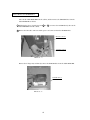
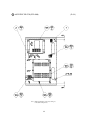
TURNING POWER ON
Turn on the AC unit's main switch to connect the power. When the power is connected, the
fluorescent light in the billboard becomes on. A few seconds later a system startup screen
appears and then an advertising screen (plying for a player screen) appears.
Time until displaying an advertising screen is not constant; it varies from some tens of second
up to several minutes. This is due to the functional characteristics of the GD-ROM system's
rechargeable battery and therefore normal.
When an advertising screen appears, sound is output from the speakers on the right and left of
the PTV cabinet. Sound is not output if you have set the function to off.
After the power is disconnected, the system can maintain the data of credit number and ranking.
The system cannot maintain, however, the fractional number of coins (not enough for one
credit) and the bonus adder count data.
Fluorescent lamp (in the Billboard) is lit.
On-screen images are outputted.
Sound is emitted.
FIG. 6. 5
24
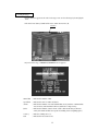
ASSEMBLING CHECK
In the TEST MODE, ensure that the assembly has been made correctly and IC BD. is
satisfactory (refer to Section 9).
In the test mode, perform the following test:
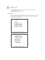
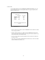
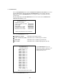
(1) MEMORY TEST
Selecting the RAM TEST and DIMM BOARD TEST on the test mode menu screen causes the
on-board memory to be tested automatically. The game board is satisfactory if the display
beside each IC No. shows GOOD.
RAM TEST
IC29 GOOD
IC35 GOOD
IC09 GOOD
IC11 GOOD
IC16 GOOD
IC20 GOOD
IC17 GOOD
IC21 GOOD
IC10 GOOD
IC12 GOOD
IC18 GOOD
IC22 GOOD
IC19 GOOD
IC23 GOOD
PRESS TEST BUTTON TO EXIT
DIMM BOARD TEST
PROGRAM VER : 1.02
DIMM SLOT 0 : GOOD
DIMM SLOT 1 : GOOD
DIMM STATUS : GOOD
CHECKING DIMM BD
DIMM0 - GOOD
DIMM1 - GOOD
IC34,35S - GOOD
IC10,11S - GOOD
GD DRIVE - GOOD
--- COMPLETE ---
PRESS TEST BUTTON TO EXIT
25
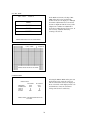
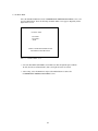
(2) C.R.T. TEST
C.R.T. TEST
PAGE 1/2
In the TEST mode menu, selecting C.R.T.
TEST allows the screen (on which the
moniter is tested) to be displayed. Although
the moniter adjustments have been made at
the time of shipment from the factory, make
judgment as to whether an adjustment is
needed by watching the test mode screen. If
it is necessary, adjust the moniter by
referring to Section 11.
RED
GREEN
BLUE
WHITE
PRESS TEST BUTTON TO CONTINUE
C.R.T. TEST
PAGE 2/2
PRESS TEST BUTTON TO EXIT
(3) INPUT TEST
Selecting the INPUT TEST on the game test
mode menu screen causes the screen (on
which each switch is tested) to be displayed.
Press each switch. If the display beside each
switch indicates "ON," the switch and
wiring connections are satisfactory.
INPUT TEST
TRIGGER
SCREEN-IN
GUN-X
GUN-Y
START
PLAYER 1
OFF
OUT
0
0
OFF
PLAYER 2
OFF
OUT
0
0
OFF
PRESS TEST AND SERVICE BUTTON
TO EXIT
26
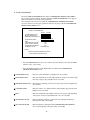
(4) OUTPUT TEST
Select OUTPUT TEST from the menu in the test mode to cause the screen (on which each lamp
and wiring connections are tested) to appear. Ensure that lamp light up satisfactorily.
OUTPUT TEST
PLAYER 1
PLAYER 2
> EXIT
SELECT WITH SERVICE BUTTON
AND PRESS TEST BUTTON
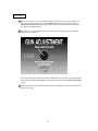
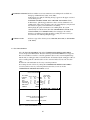
(5) GUN ADJUSTMENT
Before starting the operation, play the game by yourself and make sure that the gun
readjustment is not needed and that you can play the game without a problem. Although
completed at the factory, the gun adjustment may be necessary because after the adjustment the
product has been disassembled for packing and shipping.
For more information about the gun adjustment, see Section 9-3E.
GUN ADJUSTMENT
PLAYER1
PLAYER2
OLD : NOW
OLD : NOW
> RIGHT
aa
bb > RIGHT
aa
bb
LEFT
aa
bb
LEFT aa
bb
TOP
aa
bb
TOP
aa
bb
BOTTOM
aa
bb BOTTOM aa
bb
CENTER X aa
bb CENTER X aa
bb
Y aa
bb
Y aa
bb
DEFAULT
DEFAULT
CHECK
CHECK
SIGHT OUT
SELECT WITH START BUTTON
AND PULL TRIGGER
PRESS TEST BUTTON TO EXIT
Perform the above inspections also at the time of monthly inspection.
As for the gun adjustment described in Section (5) above, weekly confirm that the gun is
properly adjusted.
27
THE INTERFERENCE PREVENTION WIRING
In order to prevent electric shock and short circuit hazards, be sure to turn
power off before performing work.
Be careful so as not to damage wirings. Damaged wiring can cause fire,
electric shock and short circuit hazards.
Do not expose the IC BD, etc. without a good reason. Failure to observe this
can cause electric shock hazard or malfunctioning.
Work should be performed by the Location's Maintenance Man or technical
personnel. Performing work by those who do not have technical knowledge
and expertise can cause electric shock accident or malfunctioning.
When the game machines of a same or similar type are installed side by side, their sensors may
interfere with each other. To reject the interference, follow the procedure below.
The following game machines employ a same or similar type of sensor. If interference happens
to the sensors, operation of the games may be mutually disturbed.
• VIRTUA COP 2, U/R type and DX type
• THE HOUSE OF THE DEAD, U/R type and DX type
• THE HOUSE OF THE DEAD 2, U/R type and DX type
• THE LOST WORLD, U/R type and DX type
• BRAVE FIRE FIGHTERS
• SAMBA DE AMIGO
• CONFIDENTIAL MISSION, DX type
1 Disconnect the power.
2 Unlock the front-left door, and thereby remove the door from the cabinet.
3 Locate an interference rejection wire inside the cabinet.
If the game machines of a same or similar type are installed side by side, place them alternately
(place the machine with an interference rejection wire next to the machine without).
INTERFERENCE PREVENTION WIRING
SPY-60019
PHOTO 6. 6
28
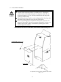
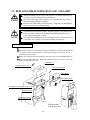
7. PRECAUTIONS TO BE HEEDED WHEN MOVING THE MACHINE
When moving the machine, be sure to unplug the power plug. Moving the
machine with the plug as is inserted can damage the power cord, and cause
fire and electric shock hazards.
When moving the machine on the floor, retract the Adjusters and ensure that
Casters make contact with the floor. During transportation, pay careful
attention so that Casters do not tread power cords and earth wires. Damaging
the power cords can cause electric shock and short circuit hazards.
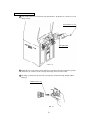
When moving the product, do not push the Front Glass. The Glass part could
be damaged and glass fractions may cause injury.
When lifting the cabinet, be sure to hold the grip portions or bottom part.
Failure to observe this may damage parts and cause injury.
Do not move the product with a GD-ROM disk inside. Remove the
GD-ROM disk before moving the product.
Failure to observe this instruction may cause the GD-ROM disk and/or GDROM drive to be damaged.
WHEN MOVING
THE PRODUCT,
DO NOT PUSH
THE FRONT GLASS.
FIG. 7
Have casters make contact with the floor.
29
GRIP
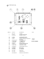
8. CONTENTS OF GAME
The following explanations apply to the case the product is functioning satisfactorily. Should
there be any moves different from the following contents, some sort of faults may have
occurred. Immediately look into the cause of the fault and eliminate the cause thereof to ensure
satisfactory operation.
While the power is connected, the fluorescent light in the billboard is on and demonstration
images and ranking data are displayed. During this advertising period, sound is also output from
the speakers on the right and left of the cabinet. Sound is not output if you have set the function
to off.
Each of the right and left start buttons is integrated with a light. The light flashes when coins are
inserted sufficiently for a play.
BILLBOARD
START BUTTON
SPEAKER
CONTROLLER
Coin Inlet
FIG. 8
30
Introduction to the Game
Based on a spy story this is a gun shooting game that enables two players to play
simultaneously.
Player, as an agent, must shoot the enemies in your way and thus try to perform a mission of
each stage. The game provides total 3 stages.
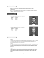
Characters of Agents
• HOWARD GIBSON [agent code : 6] (1P side)
nationality ; unknown
height
; 183cm
hair
; brown
eyes
; brown
• JEAN CLIFFORD [agent code : 15] (2P side)
nationality ; unknown
height
; 172cm
hair
; blonde
eyes
; blue
Your Missions to Perform
Stage 1:
A military satellite was hijacked by an unknown group. A suspicious radio access to the satellite
was detected and the radio source was traced to the History Museum. Your mission is to
penetrate the Museum and to collect information.
Stage 2:
The collected information revealed a group that had hijacked the satellite. The group, named as
Agares, seized Ms. Illina Mikahailova (one of the control system development staffs) and has
forced her to falsely modify the system. Your mission is to recover her who is in the train for
transference.
Stage 3:
Ms. Illina Mikahailova cooperated to successfully locate the base of the Agares. However, the
Agares members are going to leave the base after having moved the military satellite control
system into their submarines. Your mission is to penetrate the base and recover the control
system.
31
How to Play
1 Whenever you insert a coin, credit number counts up on the bottom of the screen. When you
have inserted coins enough for a play, the INSERT COIN(S) message disappears and the
PRESS START BUTTON message appears instead on the bottom of the screen. At the same
time both the start buttons flash.
2 Press either the two start buttons whichever you want to use for playing. Then a controller
adjustment screen appears.
You can adjust the gun controller by shooting a mark at the center of the screen. (This function
works only if the GUN ADJUSTMENT item has been set to ON in the GAME ASSIGNMENT
screen.)
3 After you complete a gun controller adjustment, the system displays a screen that explains your
mission of the stage.
32
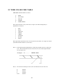
Game Screen
2P Score
1P Score
RELOAD Message
(Displayed after shooting
the bullets out.)
2P Loaded Bullets
1P Loaded Bullets
1P Remaining Life Number
2P Remaining Life Number
The loaded bullets and the remaining life number for a left-side player (1P) is displayed on the
bottom left of the screen while for a right-side player (2P) the bottom right.
Reloading the Bullets
The RELOAD message is displayed after shooting the 6 bullets out. Aim the muzzle outside the
screen and shoot to reload the bullets.
Game-over
Game is over when:
1 Your life number becomes zero (0), or
2 You have cleared the stage 3.
33
Reduction of Life Number
• A regular enemy soldier (grenade-man, bomb-man, knife-man, etc.)
appears over a sight on the screen. Shoot the soldier before the sight
becomes red; otherwise you will lose life by one.
• Shoot down the bullet from a grenade-man or bomb-man before it reaches you; otherwise
you will lose life by one.
• Shoot the knife-man before it swings down a knife on you; otherwise you will lose life by
one.
• If you shoot a civilian other than the enemy, you will lose life by one.
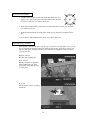
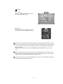
Operation of a Specific Event
Some specific events may take place stage by stage. If you succeed to play in the event, you can
expect a desirable development of the game afterward. If you fail to play in the event, you can
expect an undesirable development of the game afterward; for example the enemy will attack
you more violently.
Example of Event:
Shooting with a running rope
If you succeed:
Holding a strap that is suspended
from a running rope, you glide
down in the air and thus run after
an enemy boss.
If you fail:
Attacked by the enemies, you jump
downstairs.
34
Clearing the Stage
• A boss character appears at the end of each stage. You can clear the stage by destroying the
boss.
• The boss is not destroyed until its life meter counts down to zero (0).
Life Meter
• If you clear the stage, a MISSION COMPLETE screen appears.
normal hits ; Indicates the number of hits.
special hits ; Indicates the total of combo and justice.
combo
; Indicates the number of second and third hits out of your three continuous hits
onto an enemy. The maximum 3 hits are justified to a single enemy.
justice
; Indicates the number of justice shots. (Justice shot means that you shoot an
enemy at its hands to blast its weapons off, making it lose its fighting spirit.)
accuracy
; Indicates a hitting ratio (%).
total
; Indicates the latest total scores.
35
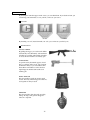
Available Items
By shooting the items that appear on the screen, you can obtain them. If you obtain an item, you
can build up your armaments, recover your life, or increase your scores.
Life Items
C Mark
M Mark
F Mark
By obtaining a set of C, M, and F marks, one each, you can increase your life by one.
Armament Items
ASSAULT RIFLE
By pulling the trigger, you can shoot the bullets
automatically and continuously. The maximum
45 bullets are available. When all the 45 bullets
are used, this item returns to an ordinary gun.
LASER SIGHT
A spot directed by the muzzle appears, in real
time, as a pointer on the screen. You can shoot
the bullets as many as you want within a time
limit. When a time limit is reached, the laser
sight disappears and this item returns to an
ordinary gun.
BODY ARMOUR
This item enables to make an enemy's attack
useless. The body armour disappears when once
used against an enemy's attack.
GRENADE
This item explodes when shot and can widely
damage the target. The grenade disappears
when once exploded.
36
Point Item
Attach_ Case
You can get 3,000 points. When this item is
shot, three floppy disks appear.
Floppy Disk
This item appears when you shoot the attach_
case item. You can get 5,000 points per piece.
3 If you want to join in the game when another player is already playing, just insert the coins and
press the unused start button; then the integrated light starts to flash. (It may be already flashing
in the event that you have the credits enough for a play.) Press the flashing start button again;
now you can play.
NOTE: You cannot join in the game if the PLEASE WAIT A MINUTE message is on the
screen.
4 When your life becomes zero (0) but you want to continuously play the game, insert the coins
enough to continue, and press the start button. (In the event that you have the credits enough to
continue, just press the start button without inserting the coins.)
5 You can enter your name in an Internet ranking mode if you have taken the 20th or higher place
in the points when the game has been over.
37
Internet Ranking (available if you have set the INTERNET RANKING item to ON in a GAME ASSIGNMENTS screen)
• If you have set the INTERNET RANKING item to ON in a GAME ASSIGNMENTS screen,
the following message appears on the upper section of an advertising screen.
INTERNET RANKING MODE: PULL TRIGGER AND INSERT COIN
• You can obtain your password to be registered in an Internet ranking, as follows:
- Make sure that an Internet ranking item has been set to on.
- Pull the trigger and insert coins to activate an Internet ranking mode.
- Enter your name.
NOTE: A CONFIDENTIAL MISSION Internet score ranking is operated at a homepage of
Hitmaker Ltd.
• For registering the password, see the homepage of Hitmaker Ltd.
(http://www.hitmaker.co.jp).
• In an Internet ranking mode, the difficulty settings are automatically reset to the values that
are specific with an Internet ranking, in the event that this function has been set to on. If you
insert the coins without pulling the trigger, however, the difficulty settings are not reset even
in the event that this function has been set to on.
PASSWORD
Keys for Getting High Points
• Destroy an enemy as soon as it appears.
Obtainable point is highest if you destroy an enemy immediately after it appears on the
screen. Point becomes lower when a sight is completed in red. The earlier you destroy an
enemy the higher the point is.
• Obtain a 'special hits' bonus point.
You obtain a bonus point if you can destroy an enemy with special hits (justice and combo).
See Page 41, "Clearing the Stage."
• Obtain a bonus point from a successful playing in the event.
You obtain a bonus point if you can succeed to play in the events that may take place stage
by stage.
38
9. EXPLANATION OF TEST AND DATA DISPLAY
By operating the switch unit, periodically perform the tests and data check. When installing the
machine initially or collecting cash, or when the machine does not function correctly, perform
checking in accordance with the explanations given in this section.
The following shows tests and modes that should be utilized as applicable.
This product's basic system consists of the NAOMI game board and the GD-ROM drive. The
system enables you to play several games one after the other just by changing a GD-ROM disk
that is to be set on the GD-ROM drive.
The product supports, therefore, the following 2 test modes:
(1) System test mode for an automatic self-diagnostic test (generally used by every product that
contains the basic system) and a coin assignment (specifically used by this product) and
(2) Game test mode for testing the input/output control devices and setting the difficulty level
(specifically used by this product).
This manual does not cover the automatic self-diagnostic test. For more information about the
system test mode, see the attached GD-ROM Service Manual.
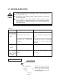
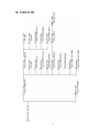
TABLE 9 EXPLANATION OF TEST MODE
ITEMS
INSTALLATION
OF MACHINE
DESCRIPTION
REFERENCE
SECTIONS
When the machine is installed, perform the following:
1. Check to ensure each is the standard setting at shipment.
2. Check each Input equipment in the INPUT TEST mode.
3. Check each Output equipment in the OUTPUT TEST mode.
4. Test on-IC-Board IC's in the SELF-TEST mode.
SERVICE MANUAL
MEMORY
This test is automatically executed by selecting RAM TEST, or
ROM BOARD TEST in the Menu mode.
SERVICE MANUAL
PERIODIC
SERVICING
Periodically perform the following:
1. MEMORY TEST
2. Ascertain each setting.
3. To test each Input equipment in the INPUT TEST mode.
4. To test each Output equipment in the OUTPUT TEST mode.
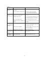
CONTROL
SYSTEM
MONITOR
IC BOARD
DATA CHECK
9-3D,E
9-3B
9-3C
SERVICE MANUAL
SERVICE MANUAL
9-3D,E
9-3B
9-3C
1. To check each Input equipment in the INPUT TEST mode.
2. Adjust or replace each Input equipment.
3. If the problem still remains unsolved, check each equipment's
mechanism movements.
SERVICE MANUAL
In the Monitor Adjustment mode, check to see if Monitor (Projector) adjustments are appropriate.
SERVICE MANUAL
1. MEMORY TEST
2. In the SOUND TEST mode, check the sound related ROMs.
SERVICE MANUAL
Check such data as game play time and histogram to adjust the
difficulty level, etc.
SERVICE MANUAL
39
9-3B,E
10
11
SERVICE MANUAL
9-3F
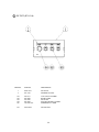
9 - 1 SWITCH UNIT AND COIN METER
Never touch places other than those specified. Touching places not specified can
cause electric shock and short circuit accidents.
STOP
IMPORTANT
Adjust to the optimum sound volume by considering the environmental
requirements of the installation location.
If the COIN METER and the game board are electrically disconnected, game
play is not possible.
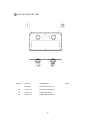
SWITCH UNIT
Open the coin chute door, and the switch
unit shown will appear.
The functioning of each SW is as follows:
SPEAKER VOLUME
TEST BUTTON
SERVICE BUTTON
DEMAGENTIZER SWITCH
FIG. 9. 1 a SWITCH UNIT
TEST BUTTON:
For the handling of the test button, refer to the following pages.
TEST
SERVICE BUTTON:
Gives credits without registering on the coin meter.
SPEAKER VOLUME:
Adjusts sound volume for all of the machines' Speakers. Adjust to an
appropriate sound volume by considering the environmental requirements
of the installation location.
DEMAGNETIZER SWITCH:
Eliminates the on-screen color unevenness due to magnetization of CRT.
First use this SW before performing the monitor's color adjustment.
SERVICE
SPEAKER
DEMAG.
COIN METER
Open the Cashbox Door by using the
key to have the Coin Meter appear
underneath the Cashbox.
COIN METER
FIG. 9. 1 b
40
9 - 2 SYSTEM TEST MODE
STOP
IMPORTANT
The contents of settings changed in the TEST mode are stored when the test
mode is finished from EXIT in the menu mode. If the power is turned off
before the TEST mode is finished, the contents of setting change become
ineffective.
Executing "BACKUP DATA CLEAR" in the SYSTEM TEST MODE does
not clear the BOOKKEEPING data in the GAME TEST mode.
Entering the TEST mode clears fractional number of coins less than one credit
and BONUS ADDER data.
Perform setting as per specified in this manual for operation. If setting not
specified is performed for operation, proper function of this product may not
be obtained.
In the SYSTEM TEST MODE, IC BD functioning can be checked, the monitor adjusted, and
the coin setting performed.
Refer to GD-ROM SERIVCE MANUAL for the details. Note that the setting of the following
items need to be performed in accordance with the instruction given.
CABINET TYPE
MONITOR TYPE
SERVICE TYPE
COIN CHUTE TYPE
:
:
:
:
2 PLAYER(S)
HORIZONTAL
COMMON
COMMON
41
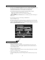
9 - 3 GAME TEST MODE
A. MENU MODE
SYSTEM MENU
CONFIDENTIAL MISSION TEST MENU
RAM TEST
JVS TEST
SOUND TEST
C.R.T. TEST
SYSTEM ASSIGNMENTS
COIN ASSIGNMENTS
BOOKKEEPING
BACKUP DATA CLEAR
CLOCK SETTING
INPUT TEST.............................................
OUTPUT TEST.........................................
GAME ASSIGNMENTS ..........................
GUN ADJUSTMENT ...............................
BOOKKEEPING.......................................
BACKUP DATA CLEAR.........................
> EXIT
B
C
C
D
E
F
DIMM BOARD TEST
GAME TEST MODE
[XXXXXXXXX
]
-> EXIT
SELECT WITH SERVICE BUTTON
AND PRESS TEST BUTTON
SELECT WITH SERVICE BUTTON
AND
PRESS TEST BUTTON
SYSTEM TEST MODE MENU
GAME TEST MODE MENU
FIG. 9. 3 a MENU MODE
• Press TEST button to display the MENU screen in the SYSTEM MODE.
• Move the arrow with the SERVICE button and select GAME TEST MODE.
Press the TEST button to display the MENU screen in the GAME TEST MODE.
• Move the arrow with the SERVICE button and select an item. Press the TEST button to
enter the selected item.
• Select the EXIT and press the TEST button to finish the test mode and return to the MENU
screen in the SYSTEM TEST MODE. Select the EXIT in the mode and press the TEST
button to finish the SYSTEM TEST MODE. The screen returns to the game mode.
42
B. INPUT TEST
Select the INPUT TEST item on the CONFIDENTIAL MISSION TEST MENU screen, and
press the TEST button. Then, the following INPUT TEST screen appears. Regularly test the
input devices on this screen.
INPUT TEST
PLAYER 1
TRIGGER
OFF
SCREEN-IN OUT
GUN-X
0
GUN-Y
0
START
OFF
PLAYER 2
OFF
OUT
0
0
OFF
PRESS TEST AND SERVICE BUTTON
TO EXIT
FIG. 9. 3 b INPUT TEST screen
• Pull the controller's trigger. Make sure that the TRIGGER item indicates ON instead of OFF,
that is, the trigger is normal.
• Point the controller toward the screen. Make sure that the SCREEN-IN item indicates IN
instead of OUT and the GUN-X and GUN-Y items change their indications within the scope
between 0 and ff, that is, the controller is normal.
• Press the start button. Make sure that the START item indicates ON instead of OFF, that is,
the button is normal.
• After testing, press the TEST and SERVICE buttons simultaneously to return to the CONFIDENTIAL MISSION TEST MENU screen.
43
C. OUTPUT TEST
Select the OUTPUT TEST item on the CONFIDENTIAL MISSION TEST MENU screen, and
press the TEST button. Then, the following OUTPUT TEST screen appears. Regularly test the
lights on this screen.
OUTPUT TEST
PLAYER 1
PLAYER 2
> EXIT
SELECT WITH SERVICE BUTTON
AND PRESS TEST BUTTON
FIG. 9. 3 c OUTPUT TEST screen
• Select the PLAYER 1 (PLAYER 2) item. Make sure that the light integrated with the
1P-side (2P-side) start button flashes, that is, the light and wires are normal.
• After testing, select the EXIT item and press the TEST button to return to the
CONFIDENTIAL MISSION TEST MENU screen.
44
D. GAME ASSIGNMENTS
Select the GAME ASSIGNMENTS item on the CONFIDENTIAL MISSION TEST MENU
screen, and press the test button. Then, the following GAME ASSIGNMENTS screen appears.
This screen enables to reset some game parameters.
New settings become effective by exiting the CONFIDENTIAL MISSION TEST MENU
screen. If you have reset any game parameters, therefore, be sure to exit the CONFIDENTIAL
MISSION TEST MENU screen.
GAME ASSIGNMENTS
GAME DIFFICULTY
BOSS DIFFICULTY
SHIFTING DIFFICULTY
COLLISION SIZE
LIFE
3
ADVERTISE CLOCK
GUN ADJUST MODE
INTERNET RANKING
CABINET TYPE
EASY
HARD
NORMAL LARGE
ON
ON
ON
XXXXXXXX
> EXIT
SELECT WITH SERVICE BUTTON
AND PRESS TEST BUTTON
FIG. 9. 3 d GAME ASSIGNMENTS screen
• Press the SERVICE button to move the > mark to any desired item to reset. Press the TEST
button to select a new setting.
• Select the EXIT item and press the TEST button, to return to the CONFIDENTIAL
MISSION TEST MENU screen.
GAME DIFFICULTY
: Indicates a game difficulty level. Eight levels are selectable.
BOSS DIFFICULTY
: Indicates a difficulty level of the fight against an enemy's boss. (Such a fight
takes place stage by stage.) Eight levels are selectable.
SHIFTING DIFFICULTY : Indicates how a difficulty level increases as the game advances. Eight levels
are selectable.
COLLISION SIZE
: Indicates violence of a collision with an enemy that may appear in the game.
Eight levels are selectable.
LIFE
: Indicates an initial life (the number of life given to a player at the beginning
of the game). Six levels (any number from 3 to 8) are selectable.
ADVERTISE CLOCK
: Indicates whether to display a clock on the screen during advertising or
plying for hire (ON), or not (OFF).
GUN ADJUST MODE
: Indicates whether to display the GUN CONTROLLER ADJUSTMENT
screen at the beginning of the game (ON), or not (OFF).
45
INTERNET RANKING: Indicates whether to activate an Internet score ranking mode available on a
homepage of Hitmaker Ltd. (ON), or not (OFF).
If this item is set to ON, the following message appears on the upper section of
an advertising screen.
INTERNET RANKING MODE: PULL TRIGGER AND INSERT COIN
In this instance, pull the trigger and insert coins to activate an Internet score
ranking mode. Then, at the end of the game, the system displays your password
that is used to register you in an Internet score ranking.
When playing the game in an Internet score ranking mode, the system
automatically reset all the items (other than ADVERTISING CLOCK, GUN
ADJUST MODE, and CABINET TYPE) to the settings specific with an
Internet score ranking mode. This automatic resetting does not occur if you
have inserted coins without pulling the trigger.
CABINET TYPE
: Indicates a type of the cabinet you use: DELUXE (DX TYPE) or STANDARD
(U/R TYPE).
E. GUN ADJUSTMENT
Select the GUN ADJUSTMENT item on the CONFIDENTIAL MISSION TEST MENU
screen, and press the TEST button. Then, the following GUN ADJUSTMENT screen appears.
This screen enables to reset the 5 correction parameters (the screen's center and right/left/top/
bottom ends). A setting procedure is described below. As instructed by the setting procedure, be
sure to actually point the controller at the screen's center and ends to decide each correction
value.
Press the 1P or 2P start button to select any correction parameter.
New settings become effective by exiting the CONFIDENTIAL MISSION TEST MENU
screen. If you have reset any correction parameters, therefore, be sure to exit the
CONFIDENTIAL MISSION TEST MENU screen.
GUN ADJUSTMENT
PLAYER1
PLAYER2
OLD : NOW
OLD : NOW
> RIGHT
aa
bb > RIGHT
aa
bb
LEFT
aa
bb
LEFT aa
bb
TOP
aa
bb
TOP
aa
bb
BOTTOM
aa
bb BOTTOM aa
bb
CENTER X aa
bb CENTER X aa
bb
Y aa
bb
Y aa
bb
DEFAULT
DEFAULT
CHECK
CHECK
SIGHT OUT
SELECT WITH START BUTTON
AND PULL TRIGGER
PRESS TEST BUTTON TO EXIT
FIG. 9. 3 e GUN ADJUSTMENT screen
46
RIGHT aa bb
: This decides a horizontal correction value at the right end. The aa column
indicates the values before resetting while the bb after.
Point the controller to a screen's right end, aim at a square mark, and pull the
trigger; thereby decide a correction value.
It is unnecessary to consider a vertical correction in this action.
LEFT aa bb
: This decides a horizontal correction value at the left end. The aa column
indicates the values before resetting while the bb after.
Point the controller to a screen's left end, aim at a square mark, and pull the
trigger; thereby decide a correction value.
It is unnecessary to consider a vertical correction in this action.
TOP aa bb
: This decides a vertical correction value at the top end. The aa column indicates
the values before resetting while the bb after.
Point the controller to a screen's top end, aim at a square mark, and pull the
trigger; thereby decide a correction value.
It is unnecessary to consider a horizontal correction in this action.
BOTTOM aa bb
: This decides a vertical correction value at the bottom end. The aa column
indicates the values before resetting while the bb after.
Point the controller to a screen's bottom end, aim at a square mark, and pull the
trigger; thereby decide a correction value.
It is unnecessary to consider a horizontal correction in this action.
CENTER X(Y) aa bb : This decides a correction value at the center. X indicates a horizontal direction
while Y a vertical direction. The aa column indicates the values before resetting
while the bb after.
Point the controller to a screen's center, aim at a square mark, and pull the
trigger; thereby decide a correction value.
DEFAULT
: This returns the correction values to those before resetting.
CHECK
: This enables to perform a gun adjustment.
Select the CHECK item and point the controller to a screen. A round cursor (red
for 1P and blue for 2P) appears on the screen to indicate a position of your
hitting. Referring to the cursor, you can perform a gun adjustment.
SIGHT OUT
: The SIGHT OUT message appears when you point the controller to outside the
screen.
47
F. BOOKKEEPING
Select the BOOKKEEPING item on the CONFIDENTIAL MISSION TEST MENU screen, and
press the TEST button. Then, the following BOOKKEEPING 1/2 screen appears. Press the
TEST button again; the BOOKKEEPING 2/2 screen appears. These screens show the latest
operation data.
Press the TEST button in the BOOKKEEPING 2/2 screen to return to the CONFIDENTIAL
MISSION TEST MENU screen.
BOOKKEEPING 1/2
NUMBER OF GAMES
TOTAL (POWER ON) TIME
GAME TIME
PLAY TIME
AVERAGE PLAY TIME
LONGEST PLAY TIME
SHORTEST PLAY TIME
0
00H 00M 00S
00H 00M 00S
00H 00M 00S
00H 00M 00S
00H 00M 00S
00H 00M 00S
PRESS TEST BUTTON TO CONTINUE
FIG. 9. 3 fa BOOKKEEPING 1/2 screen
NUMBER OF GAMES
: This indicates the number of plays.
TOTAL (POWER ON) TIME: This indicates the accumulated power-on hours.
GAME TIME
: This indicates the accumulated operation hours.
PLAY TIME
: This indicates the accumulated playing hours (1P+2P).
BOOKKEEPING 2/2
The BOOKKEEPING 2/2 screen
indicates the number of plays per each
playing period. Use the data when
setting a difficulty level.
TIME HISTOGRAM
0M00S - 0M29S 0
0M30S - 0M59S 0
1M00S - 1M29S 0
1M30S - 1M59S 0
2M00S - 2M29S 0
2M30S - 2M59S 0
3M00S - 3M29S 0
3M30S - 3M59S 0
4M00S - 4M29S 0
4M30S - 4M59S 0
5M00S - 5M29S 0
5M30S - 5M59S 0
6M00S - 6M29S 0
6M30S - 6M59S 0
7M00S - 7M29S 0
7M30S - 7M59S 0
8M00S - 8M29S 0
8M30S - 8M59S 0
9M00S - 9M29S 0
9M30S - 9M59S 0
OVER 10M00S 0
PRESS TEST BUTTON TO EXIT
FIG. 9. 3 fb BOOKKEEPING 2/2 screen
48
G. BACKUP DATA CLEAR
Select the BACKUP DATA CLEAR item on the CONFIDENTIAL MISSION TEST MENU
screen, and press the TEST button. Then, the following BACKUP DATA CLEAR screen
appears. This screen enables to clear the data of bookkeeping and high-ranking scorers.
BACKUP DATA CLEAR
YES(CLEAR)
> NO (CANCEL)
SELECT WITH SERVICE BUTTON
AND PRESS TEST BUTTON
FIG. 9. 3 g BACKUP DATA CLEAR screen
• To clear the data:
Press the SERVICE button to move the > mark to YES, and press the TEST button. When
clearing is finished, the COMPLETED message appears on the screen. Press the TEST
button, in this instance, to return to the CONFIDENTIAL MISSION TEST MENU screen.
• Not to clear the data:
Press the SERVICE button to move the > mark to NO, and press the TEST button. This
action enables you to immediately return to the CONFIDENTIAL MISSION TEST MENU
screen.
• Even after you have cleared the backup data, the settings in the GAME ASSIGNMENTS and
GUN ADJUSTMENT screens remain unchanged.
• Even after you have cleared the backup data, the coin- and credit-related data are not cleared.
To clear the coin- and credit-related data, select the BACKUP DATA CLEAR item in the
SYSTEM MENU screen and press the TEST button.
49
10. CONTROLLER
In order to prevent an electric shock and short circuit, be sure to turn power
off before performing work by touching the interior parts of the product.
Be careful so as not to damage wirings. Damaged wiring can cause an
electric shock or short circuit accident.
Be very careful when soldering. Handling a soldering iron carelessly may
result in a fire or a burn.
When securing the plastic-made parts, do not excessively fasten screws and nuts.
Failure to observe this may damage the parts and cause injury due to fragments
resulting from damage.
In the cases where the controller's operation is not satisfactory or the controller sight deviates
from the direction in which the controller is pointed, the controller's interior parts may have
been damaged. Replace the parts by disassembling the controller in the following procedure:
Also, be sure to perform sighting check in the test mode when the controller parts are replaced.
REPLACING THE MICROSWITCH
1 Disassemble the controller.
2 Pull out the microswitch from COVER RIGHT.
3 Take out the microswitch by removing the soldering from it.
4 Bend the new Microswitch Actuator as shown.
5 Solder the new microswitch and assemble the controller.
6 By operating the Trigger, check if the Microswitch can be turned ON/OFF correctly.
REPLACING THE SENSOR UNIT
1 Disassemble the controller.
2 Remove the sensor unit from COVER.
50
CAP NUT (9)
M3
COVER RIGHT
MICROSWITCH
509-5080
SENSOR UNIT
JPT-2030
Approximately 7 mm
Approximately 8 mm
MICROSWITCH ACTUATOR
BENDING WORK
COVER LEFT
SCREW (6)
M3 X 25
FIG. 10
51
SCREW (3)
M3 X 8
11. MONITOR
11 - 1CAUTIONS AND WARNINGS CONCERNING THE SAFETY FOR HANDLING THE MONITORS
Before handling the monitors, be sure to read the following explanations and comply with the
caution/warning instructions given below. Note that the caution/warning symbol marks and
letters are used in the instructions.
Indicates that handling the monitors
erroneously by disregarding this warning may
cause a potentially hazardous situation,
which could result in death or serious injury.
Indicates that handling the monitors by
disregarding this caution may cause a
potentially hazardous situation, which could
result in personal injury and or material
damage.
Indicates that access to a specific part of the
equipment is forbidden.
Indicates the instruction to disconnect a
power connector or to unplug.
When performing such work as installing and removing the monitor, inserting and disconnecting
the external connectors to and from monitor interior and the monitor, be sure to disconnect the
power connector (plug) before starting the work. Proceeding the work without following this
instruction can cause electric shock or malfunctioning.
Using the monitor by converting it without obtaining a prior permission is not allowed. SEGA
shall not be liable for any malfunctioning and accident caused by said conversion.
Primary side and Secondary side
SECONDARY SIDE
The monitor's circuit which is divided into the Primary side
(Chassis, CRT)
and Secondary side, is electrically isolated. Do not touch the
primary side, or do not touch both the primary side and the
PRIMARY
secondary side simultaneously. Failing to observe the
SIDE
instruction can cause electric shock and this is very
dangerous. When making monitor adjustments, use a nonconductive driver and make adjustment without touching any
part other than the Adjustment V. R. and knob. Also, be sure
not to cause a short-circuit to the Primary side and Secondary
side. If short-circuited, it can cause electric shock or
malfunctioning, which is very dangerous.
High-tension Voltage
Some of the parts inside monitor are subject to high-tension voltage in excess of 20,000 volts and
very dangerous. Therefore, do not touch the monitor interior. Should soldering & paper wastes,
etc. be mixed in the monitor interior, turn the power off so as not to cause malfunctioning or fire
hazard. ANODE CAP
REAR PART
PRIMARY SIDE
ANODE LEAD
Approx. 29 kV
MAIN BD
DEMAGNETIZER
COIL
FOCUS LEAD
(black)
Approx. 10 kV
DEMAGNETIZER
COIL
NECK PCB
Approx.
10 kV
SECONDARY SIDE
(Chassis, sheet metal work, CRT, etc.)
Disconnect or unplug
FBT Approx.
29 kV
Connecting the CRT and PCB
For combining the CRT and PCB, use the specified part No. to maintain the status of adjustments
made at the factory. The anode of the CRT itself will be accumulatively charged as time elapses,
generating high-tension voltage which is very dangerous. The monitor should be used with the
Chassis, CRT and PCB assembled. When repair, etc. is required at the time of malfunctioning,
be sure to send it in an "as is assembled" condition. If these are disassembled, what's charged to
said high tension voltage can be discharged, causing a very hazardous situation. Therefore, under
no circumstances should it be disassembled.
52
Static Electricity
Touching the CRT surface sometimes causes you to slightly feel electricity. This is because the
CRT surfaces are subject to static and will not adversely affect the human body.
Installation and removal
Ensure that the Magnetizer Coil, FBT (Fly-Back Transformer), Anode Lead and Focus Lead are
not positioned close to the sheet metal work's sharp edges, etc. and avoid damaging the insulated
portions so as not to cause electric shock and malfunctioning. (For the name of parts, refer to the
above Figures).
53
For the purpose of static prevention, special coating is applied to the CRT face of
this product. To protect the coating, pay attention to the following points.
Damaging the coating film can cause electric shock to the customers.
Do not apply or rub with a
hard item (a rod with
pointed edge, pen, etc.) to
or on the CRT surfaces.
Avoid applying stickers,
seals, etc. on the CRT face.
Aluminum Foil
Do not remove aluminum
foils from the CRT corners.
Removing the aluminum
foils can cause static
prevention effects to be
lowered.
11 - 2 CAUTIONS TO BE HEEDED WHEN CLEANING THE CRT SURFACES
Use care when handling the glass made parts. If glass made parts are damaged,
the glass fractions can cause injury.
When cleaning the CRT, be sure to use a soft, dry cloth. Do not use
chemicals such as thinner, benzene, etc.
Apply anti-static agent,which prevents dust attachment, only to the CRT face.
STOP
IMPORTANT
Be sure to turn power off before cleaning the CRT.
Then, you must remove the front glass as
follows:
1 Remove the upper glass holder.
2 Insert your hand into a revealed square slot.
3 Draw out the glass toward you.
MONITOR
GLASS HOLDER UPPER
TRUSS SCREW (3), black
M5 X 16
FRONT GLASS
FIG. 11. 2
54
11 - 3 ADJUSTMENT METHOD
Monitor adjustments have been made at the time of shipment. Therefore, do
not make further adjustment without a justifiable reason. Adjusting the
monitor which contains high tension parts is a dangerous work. Also, an
erroneous adjustment can cause deviated synchronization and image fault,
resulting in malfunctioning.
When making adjustment, utilize a resinous Alignment Rod. Servicing with
bare hand or using conductive tools can cause electric shock.
Be sure to perform appropriate adjustment of the monitor (projector). For
operation of this machine, do not leave monitor's flickering or deviation as is.
Failure to observe this can have a bad influence upon the players' or the
customers' physical conditions.
Remove the back door at the rear of the cabinet, and the monitor adjustment knob appears.
TAMPERPROOF SCREW(3), black
M4 X 30,flat washer used
BACK DOOR
FIG. 11. 3 a
For adjustment, use the Resinous Adjustment Rod of 9mm.
FIG. 11. 3 b
55
NANAO monitor: 2 0 0 - 5 9 2 7 - 0 1 (31k mode)
1 R-GAIN......
2 G-GAIN .......... Controls colors.
3 B-GAIN......
4 BRIGHT.......... Controls screen brightness.
5 H. SIZE ........... Controls horizontal screen size.
7 H. POSI ........... Controls horizontal display position on screen.
8 V. SIZE ........... Controls vertical screen size.
10 V. POSI ........... Controls vertical display position on screen.
11 CONTRAST.... Adjusts image contrast.
56
12. COIN SELECTOR
HANDLING THE COIN JAM
If the coin is not rejected when the REJECT button is pressed, open the coin chute door and
open the selector gate. After removing the jammed coin, put a normal coin in and check to see
that the selector correctly functions.
CLEANING THE COIN SELECTOR
GATE
Remove and clean smears by using a
soft cloth dipped in water or diluted
chemical detergent and then
squeezed dry.
Never apply machine oil, etc. to the
Coin Selector.
After cleaning the Coin Selector,
insert a regular coin in the normal
working status and ensure that the
Selector correctly functions.
STOP
IMPORTANT
1
2
3
4
5
6
FIG. 12 a
The coin selector should be cleaned once every
3 months. When cleaning, follow the procedure
below:
Turn the power for the machine OFF. Open the
coin chute door.
Open the gate and dust off by using a soft brush
(made of wool, etc.).
Remove and clean smears by using a soft cloth
dipped in water or diluted chemical detergent
and then squeezed dry.
Remove the CRADLE.
When removing the retaining ring
(E ring), be very careful so as not to bend the
rotary shaft.
Remove stain from the rotary shaft and shaft
receiving portions by wiping off with a soft
cloth, etc.
After wiping off as per 5 above, further apply
a dry cloth, etc. to cause the coin selector to dry
completely.
COIN INSERTION TEST
Once every month, when performing the
Coin SW Test, simultaneously check the
following:
Does the Coin Meter count satisfactorily?
Does the coin drop into the Cashbox
correctly?
Is the coin rejected when inserted while
keeping the Reject Button pressed down?
CRADLE
FIG. 12 b
Insert a coin
while keeping the
Reject Button
pressed down and
check if it is
rejected.
COIN METER
FIG. 12 c
57
13. REPLACING THE FLUORESCENT LAMP, AND LAMPS
When performing work, be sure to turn power off. Working with power on
can cause electric shock and short circuit hazards.
The Fluorescent Lamp, when it gets hot, can cause burn. Be very careful
when replacing the Fluorescent Lamp.
Be sure to use lamps of the designated rating. Using lamps of undesignated
rating can cause a fire or malfunctioning.
To perform work safely and securely, be sure to prepare a step which is in a
secure and stable condition. Performing work without using the step can
cause violent falling down accidents.
Be careful when handling the plastic made parts. Failure to observe this may
cause injury due to damage or fragments resulting from damage.
INSIDE THE BILLBOARD
1 Disconnect the power.
2 Remove the 3 truss head screws from the bottom of the billboard, and draw out the billboard
case toward you. Be careful not to draw out too much; otherwise it may drop down and
eventually cause an accident.
3 Remove the 4 truss head screws, and thereby remove the lamp cover B and billboard plate.
4 Remove the 2 countersunk screws, and thereby remove the lamp cover A. Now, replace the
fluorescent light with a new one.
LAMP COVER A
FLATHEAD SCREW (2), black
M4 X 8
TRUSS SCREW (4), black
M4 X 12,flat washer used.
LAMP COVER B
BILLBOARD PLATE
FLUORESCENT LAMP 20W:390-5251-20-02
GLOW BULB: 390-5638-1E
BILLBOARD CASE
TRUSS SCREW(3), black
M4 X 20, flat washer used.
FIG. 13 a
When performing
work, prepare a step.
58
REPLACING THE LAMP
1 Take out the 6 truss screws and remove the Switch Panel. At this time, be careful so as not to
damage wiring.
TRUSS SCREW (6), black
M4 X 12
SWITCH PANEL
FIG. 13 b
2 Hold both sides of the switch portion with fingers and pull out from the button's base portion.
At this time, be careful so as not to damage the wiring connected to the switch.
3 The lamp is positioned at the end of the switch portion. Pull out the lamp straight without
turning it.
WEDGE BULB,6V 3W
390-5160
FIG. 13 c
59
14. PERIODIC INSPECTION TABLE
The items listed below require periodic check and maintenance to retain the performance of this
machine and to ensure safe business operation.
When handling the controller, the player will be in direct contact with it . In order to always
allow the player to enjoy the game, be sure to clean it regularly. Also, it is advisable to provide
wet tissue, etc. available for player use.
Be sure to check once a year to see if Power Cords are damaged, the plug is
securely inserted, dust is accumulated between the Socket Outlet and the
Power Plug, etc. Using the product with dust as is accumulated can cause fire
and electric shock hazards.
Periodically once a year, request the place of contact herein stated or the
Distributor, etc. where the product was purchased from, as regards the internal
cleaning. Using the product with dust as is accumulated in the interior
without cleaning can cause a fire or accident. Note that cleaning the interior
parts can be performed on a pay-basis.
TABLE 14
Item
Interval
Reference
CABINET
Check Adjusters'contact with surface.
Daily
3
CONTROLLER
Cleaning
As necessary
Sight check
Weekly
9,10
Check SWes.
Monthly
9,10
COIN CHUTE DOOR
MONITOR
Check COIN SW.
Monthly
9
Coin insertion test.
Monthly
12
Cleaning of COIN SELECTOR.
Trimonthly
12
Cleaning CRT face.
Weekly
11
Check adjustments.
Monthly
6,9,11
FRONT GLASS,MIRROR
Cleaning
Weekly
See next page.
GAME BD
Check settings.
Monthly
9,*GD-ROM
MEMORY TEST.
Monthly
9,*GD-ROM
INTERIOR
Cleaning
Annually
See above.
POWER SUPPLY PLUG
Inspection and cleaning
Cabinet surfaces
Cleaning
As necessary.
See below.
*The 'GD-ROM' above indicates the GD-ROM SERVICE MANUAL
CLEANING THE CABINET SURFACES
When the cabinet surfaces are badly soiled, remove stains with a soft cloth dipped in water or
diluted (with water) chemical detergent and squeezed dry. To avoid damaging surface finish, do
not use such solvents as thinner, benzine, etc. or abrasives, bleaching agent and chemical
dustcloth.
60
CLEANING THE FRONT GLASS AND MIRROR
When cleaning, be sure to comply with the following CAUTION and instructions so as to
ensure that the front glass and mirror are not damaged.
Use care when handling glass made parts. When the glass is damaged, fragments
of glass can cause injury.
STOP
IMPORTANT
Be sure to use the accessory glass cleaner or high-efficiency alkaline
cleansing water. To avoid damaging the glass surfaces, do not use solutions
such as thinner and alcohol, or abrasives, nor bleaching agents.
Use a soft cloth.
When removing an attached large particle of dust (or foreign matter), do not
rub with a cloth.
Remove the front glass when cleaning the front glass and mirror. First, remove GLASS
HOLDER UPPER only. Then, put your hand through the square hole in the back side of
GLASS HOLDER UPPER, and pull the front glass toward you.
GLASS HOLDER UPPER
TRUSS SCREW (3), black
M5 X 16
FRONT GLASS
FIG. 14
61
15. TROUBLESHOOTING
In order to prevent electric shock and short circuit, be sure to turn power off
before performing work.
Be careful so as not to damage wirings. Damaged wiring can cause electric
shock or short circuit.
After removing the cause of the functioning of the Circuit Protector, reinstate
the Circuit Protector. Depending on the cause of the functioning, using the
Circuit Protector as is without removing the cause can cause generation of
heat and fire hazard.
In case a problem occurs, first check wiring connector connections.
TABLE 15 a
PROBLEMS
When the main
SW is turned ON,
the machine is not
activated.
CAUSE
COUNTERMEASURES
The power is not ON.
Firmly insert the plug into the outlet.
Incorrect power source/voltage.
Make sure that the power supply/voltage are
correct.
AC UNIT CIRCUIT PROTECTOR
functioned due to instantaneous
overcurrent.
First, remove the cause of overcurrent and
reinstate the circuit protector to its original
status (see 4 , Section 6, Refer to the
following).
The color on Image adjustment is inappropriate.
MONITOR screen
is incorrect.
Adjust appropriately (see Sec.11).
The on-screen
image of the
monitor sways
and or shrinks.
Make sure that the power supply and voltage
are correct.
The power source and voltage are not
correct.
CIRCUIT PROTECTOR
CIRCUIT PROTECTOR
Functions due to the activation of
bimetal. To restore the function,
wait for approximately one minute
or longer until the bimetal cools off.
(Press the Button.)
FIG. 15 a
62
TABLE 15 b
PROBLEMS
No sound
emitted.
CAUSE
is
Controller
sighting is not
s a t i s f a c t or y.
COUNTERMEASURES
Sound volume adjustment is not
appropriate.
Adjust sound volume (see Sec. 9).
Board and Amplifier malfunctioning.
Perform the sound test and confirm
(see GD-ROM SERVICE MANUAL).
Due to environmental changes, etc.,
sighting became inappropriate.
Perform sighting adjustment in the test mode
(see Sec. 9).
LED BD malfunctioning.
Check to ensure that the LED lights up. If it
does not light up, replace (see next page).
Sensor Unit malfunctioning.
Replace the Sensor Unit (see Sec.10).
LED BD, Front Glass, and Mirror are
soiled.
Wipe off soiled surfaces (see Sec. 14 and
next page).
During game play, Malfunctioning of microswitch.
the Controller is
not operable for
shooting.
Malfunctioning of LED BD.
Check for ON and OFF in the INPUT test
and if it is not functioning, replace the
microswitch (see Sec.10).
Check if the LED is lit, and if it is not lit,
replace (see next page).
Malfunctioning of Sensor Unit.
Replace the Sensor Unit.
The Fluorescent
lamp does not
light up.
The Fluorescent tube is burnt out.
Replace the Fluorescent tube
(see Sec. 13).
The Lamp does
not light up.
Lamp malfunctioning.
Replace the Lamp (see Sec. 13).
63
REPLACEMENT OF LED BD
If the light emission of 2 LED's
can not be seen, the fault or
malfunctioning may be considered.
Replace by using the following
procedure. Also, when wiping off
the soils, remove the ASSY
SENSOR as per the same
procedure.
If light emission from the 2 LED's can not be seen, replace.
FIG. 15 b
1 Turn power off.
2 Remove the Back Door.
ASSY SENSOR
3 Disconnect the ASSY SENSOR
CONNECTOR.
4 Unclamp the grounding cable.
Remove the hexagon head nut,
and remove a round grounding
terminal from a screw shank.
HEXAGON NUT
M4, flat & spring
washers used.
5 Pull out the ASSY SENSOR.
FIG. 15 c
LED BD
U NUT (2)
M3, ,plastic washer used.
6 Disconnect the connector from the
both ends of the LED BD which
shows defects.
7 Take out the 2 U Nuts to remove and
replace the LED BD.
FIG. 15 d
64
16. GAME BOARD
In order to prevent electric shock and short circuit hazards, be sure to turn
power off before performing work.
Be careful so as not to damage wirings. Damaged wiring can cause fire,
electric shock or short circuit.
Do not expose the Game BD, etc. without a good reason. Failure to observe
this can cause electric shock hazard or malfunctioning.
In this product, setting changes are made during the test mode. The Game BD
need not be operated. Use the Game BD, etc. as is with the same setting made
at the time of shipment so as not to cause electric shock and malfunctioning.
The electronic parts on the IC Board may be damaged due to human body's
static electricity. Before performing IC Board related work, be sure to
discharge physically accumulated statics by touching grounded metallic
surfaces, etc.
16 - 1 REMOVING THE GAME BOARD
Turn off the main switch to disconnect the power.
Unlock the front-left door, and thereby remove the door from the cabinet.
UNLOCK
PHOTO 16. 1 a
65
3 Take out the ASSY MAIN BD (with the NAOMI board) from the cabinet. Remove the 7
connectors from the upper section of the rear of the door.
Disconnect the connector.
PHOTO 16. 1 b
4 Remove the D-SUB connector from the filter board (a part of the NAOMI board on the ASSY
MAIN BD). Unclamp the cable with the D-SUB connector.
D-SUB connector
PHOTO 16. 1 c
66
5 Remove the 2 wing bolts that fix the ASSY MAIN BD's base (a wooden base).
6 Take out the ASSY MAIN BD from the cabinet. In this instance, be careful not to catch the
wires on or in the parts.
WING BOLT (2)
M4 X 30, flat washer used
PHOTO 16. 1 d
7 Place the ASSY MAIN BD on a flat horizontal surface.
8 Remove all the connectors from the filter board on the NAOMI board. Also remove the GD
cable connector from the DIMM board.
9 Remove the 4 screws that fix the NAOMI game board.
SCREW (4)
M4 X 16, w/flat & spring washers
Disconnect all connectors
D-SUB connector
GD cable connector
FIG. 16. 1
67
How to Remove the GD-ROM Drive
Take out the ASSY MAIN BD from the cabinet; and then remove the GD-ROM drive from the
ASSY MAIN BD as follows:
1 Following the above described actions 1 to 7 (to remove the NAOMI board), take out the
ASSY MAIN BD from the cabinet.
2 Remove the GD cable connector and the power cord connector from the GD-ROM drive.
GD Cable connector
AC Cable connector
PHOTO 16. 1 e
Remove the 4 flange nuts, and thereby remove the GD-ROM drive from the ASSY MAIN BD.
FLANGE NUT (4)
M4
PHOTO 16. 1 f
68
16 - 2 COMPOSITION OF GAME BOARD
ASSY CASE NAO GD SPY USA (840-0050D-01) :USA
ASSY CASE NAO GD SPY EXP (840-0050D-02) :OTHERS
ASSY CASE NAO GD SPY KOR (840-0050D-03) :KOREA
ASSY CASE NAO GD SPY AUS (840-0050D-04) :AUSTRALIA
TRUSS SCREW (1)
M3 X 70,chrome plated
TRUSS SCREW (3)
M3 X 30,chrome plated
DIP SW
840-0001A-01 ASSY CASE NAOMI MAIN BD USA
840-0001A-02 ASSY CASE NAOMI MAIN BD EXP
840-0001A-03 ASSY CASE NAOMI MAIN BD KOR
840-0001A-04 ASSY CASE NAOMI MAIN BD AUS
DIMM BD NAO SPY
840-0050B
FIG. 16. 2 a
DIP SW SETTING
In this product, set the DIP SW to OFF.
FIG. 16. 2 b
69
17. DESIGN RELATED PARTS
For the Warning Display stickers, refer to Section 1.
70
18. PARTS LIST
71
1 TOP ASSY SPY U/R
(D-1/2)
72
1 TOP ASSY SPY U/R
ITEM NO.
(D-2/2)
PART NO.
DESCRIPTION
1
2
3
4
10
11
12
13
15
16
18
19
SPY-10001
SPY-2300
422-0847-01
421-7907- ~
421-8479-01
440-DS0013XEG
SGM-4323
440-WS0002XEG
440-CS0109-EG
PRC-1045
440-CS0186-EG
421-8885
ASSY CABINET U/R
ASSY SW PANEL
PLAY INSTR SH SPY U/R ENG
DENOMI SH ~
STICKER INSTR SUNLIGHT ENG
STICKER D MONITOR ENG
POLY COVER 900 X 1300 X 1800
STICKER W POWER OFF ENG
STICKER C ZMB U/R ENG
COVER
STICKER C EPILEPSY 40 ENG
STICKER CAUTION FORK
201
203
000-T00412-0B
008-T00412-0B
M SCR TH BLK M4 X 12
TMP PRF SCR TH BLK M4 X 12
401
402
403
405
406
407
408
409
601-6604-70
SGM-2675
420-6602-01
220-5576
SGM-4111
509-5080
390-5160
600-6664-02
410
600-6729
600-6618
600-6619
SPY-0003
SPY-0004
090-0174
280-5009-01
105-5435
012-P00408
050-F00400
540-0006-01
420-6620-01
610-0625-0001
SPY-0005
011-T03512
CARTON BOX 70
POLYETHYLENE BAG, 240 X 370
OWNERS MANUAL SPY UR ENG
KEY MASTER FOR 220-5575
KEY BAG (SGB-1035X)
SW MICRO TYPE
LAMP WG B TYPE 6V 3W (C2R)
WIRE HARN EARTH W/LUG M6
NOT USED
AC CABLE CONNECT TYPE 15A
AC CABLE CONNECT TYPE FOR EXP
AC CABLE CONNECT TYPE FOR UK
BILLBOARD PLATE SPY U/R
BILLBOARD PLATE R SPY UR
GLASS CLEANER NAC S-100
CORD CLAMP 21
GD DRIVE BRKT STD
TAP SCR #2 PH 4 X 8
FLG NUT M4
WRENCH M4 TMP SCR
SERVICE MANUAL NAOMI GD ENG
GD SOFT SPY
PLATE HOLDER
TAP SCR TH 3.5 X 12
105-5356
421-8740
421-6690-05
421-6690-03
421-6690-06
SHIPPING BRKT
CAUTION INSTR COP U/R
STICKER 240V
STICKER 220V
STICKER 110V
412
413
414
415
416
417
418
419
420
421
422
423
/
/
/
/
/
73
NOTE
TAIWAN
OTHERS
TAIWAN
OTHERS
HONG KONG
AC 240V AREA
AC 220V AREA
AC 110V AREA
2 ASSY CABINET U/R (SPY-10001)
(D-1/2)
74
2 ASSY CABINET U/R (SPY-10001)
(D-2/2)
ITEM NO.
PART NO.
DESCRIPTION
1
2
3
4
5
6
7
8
9
10
11
12
13
14
15
16
17
18
SPY-1500
SPY-1540
SPY-1550
SPY-1570
HOD-3500
SPY-2200
SPY-4200
SPY-4300
JPT-1510
AIN-1032
AIN-1033
JPT-1509
AIN-1035
AIN-1044
AIN-1038
AIN-1039
AIN-1040
253-5366
ASSY SUB-CABI U/R
AC UNIT
ASSY SENSOR
ASSY MONITOR 2934
ASSY BILLBOARD
ASSY CTRL PNL U/R
ASSY MAIN BD U/R
ASSY ELEC BD U/R
FRONT GLASS
RUBBER PACKING
GLASS HOLDER UPPER
GLASS HOLDER LOWER
CUSHION
MIRROR BRKT
MIRROR
MIRROR SASH
MIRROR HOLDER
CASH BOX
201
202
203
204
205
206
207
208
209
210
211
212
213
214
215
216
000-T00520-0B
050-F00400
030-000616-S
060-F00600
000-T00420-0B
068-441616-0B
000-F00416
000-T00525-0B
069-000017-0B
032-000430
068-441616
000-T00516-0B
000-P00412-W
050-H00400
060-S00400
060-F00400
M SCR TH BLK M X ~20
FLG NUT M4
HEX BLT W/S M6 X 16
FLT WSHR M6
M SCR TH BLK M4 X 20
FLT WSHR BLK 4.4-16 X 1.6
M SCR FH M4 X 16
M SCR TH BLK M5 X 25
FLT WSHR BLK 5.5-16 X 1.6
WING BLT M4 X 30
FLT WSHR 4.4-16 X 1.6
M SCR TH BLK M5 X 16
M SCR PH W/FS M4 X 12
HEX NUT M4
SPR WSHR M4
FLT WSHR M4
75
3 ASSY SUB-CABI U/R (SPY-1500)
(D-1/3)
76
3 ASSY SUB-CABI U/R (SPY-1500)
ITEM NO.
(D-2/3)
PART NO.
DESCRIPTION
1
2
3
4
5
6
7
8
9
10
11
12
13
14
15
16
17
18
19
20
21
22
23
24
25
26
27
28
29
30
SPY-1080
SPY-1530
610-0549-01
SPY-1501
SPY-1502
SPY-1503
SPY-1504
SPY-1505
JPT-1507
ARC-1006
AIN-1008
COP-1503
COP-1506
DP-1148X
DP-1167
253-5460-01
105-5169
105-5171
105-5258-01
117-0062
117-5098
117-5233
117-5284
253-5396-91
421-7501-02
JPT-1508
SCR-1008
SPY-1506
SPY-1507
SPY-1508
FAN UNIT
SW UNIT
METER UNIT SINGLE
WOODEN CABINET U/R
STICKER SIDE L SPY U/R
STICKER SIDE R SPY U/R
FRONT DOOR L
FRONT DOOR R
HOOK BRKT
LEG BRACKET
MONITOR SUPPORT BRKT
BACK DOOR
WIRE COVER
LKG TNG
TNG LKG
AIR VENT BLACK
LOCK BRACKET W
CHUTE PLATE SINGLE
SHIPPING HOOK BRKT RED
PLATE LOCK RETAINER
TNG RETAINER PLATE
PLATE LEG BRACKET BLACK
PLATE 6-80 BLACK
CABINET HANDLE
STICKER 6.3V 0.15A
PROTECT SHEET B
NUT PLATE FOR CASTER
COVER SIDE
EARTH PLATE
CLAMP BASE
101
220-5482-91- ~
220-5237-92- ~
220-5574
220-5575
280-5275-SR10
310-5029-F20
601-9377
601-6224
601-5699X
280-5009-01
280-5207
280-5169
ASSY C.C ~
ASSY C.C ~
CAM LOCK W/KEYS
CAM LOCK MASTER W/O KEY
CORD CLAMP SR10
SUMITUBE F F 20MM
CASTER FAI=75
CASTER 75
LEG ADJUSTER BOLT M16 X 75
CORD CLAMP 21
HARNESS LUG CC-1005
CORD CLAMP TL-20S
102
103
104
105
106
107
108
109
110
77
3 ASSY SUB-CABI U/R (SPY-1500)
ITEM NO.
(D-3/3)
PART NO.
DESCRIPTION
201
202
203
204
205
206
207
208
209
210
211
212
213
214
215
216
217
218
220
221
222
000-P00416-W
000-P00420-W
000-T00420-0B
008-T00430-0B
011-T00312
011-T03512
030-000630-SB
030-000830-SB
031-000630-0B
050-F00600
050-H01600
060-F00600
060-F00800-0B
068-441616-0B
011-F00310
030-000625-S
011-P00316-0B
000-P00408
050-H00400
060-S00400
060-F00400
M SCR PH W/FS M4 X 16
M SCR PH W/FS M4 X 20
M SCR TH BLK M4 X 20
TMP PRF SCR TH BLK M4 X 30
TAP SCR TH 3 X 12
TAP SCR TH 3.5 X 12
HEX BLT BLK W/S M6 X 30
HEX BLT W/S BLK M8 X 30
CRG BLT BLK M6 X 30
FLG NUT M6
HEX NUT M16
FLT WSHR M6
FLT WSHR BLK M8
FLT WSHR BLK 4.4-16 X 1.6
TAP SCR FH 3 X 10
HEX BLT W/S M6 X 25
TAP SCR #1 PH BLK 3 X 16
M SCR PH M4 X 8
HEX NUT M4
SPR WSHR M4
FLT WSHR M4
301
302
303
305
306
SPY-6001
SPY-6002
600-6455-02
SPY-61011
600-6972-0120
ASSY WIRE CABI DC
ASSY WIRE CABI AC
WIRE HARN C.C DOOR SINGLE
WH LED EXT
WIRE HARN EARTH ID5 0120MM
/
/
/
000-P00430-W
SPY-4600
SPY-4500
M SCR PH W/FS M4 X 30
ASSY XFMR 200V AREA
ASSY XFMR 100V AREA
78
NOTE
AC 220 ~ 240V AREA
AC 110 ~ 120V AREA
4 FAN UNIT (SPY-1080)
CONNECTOR
ITEM NO.
PART NO.
DESCRIPTION
1
SPY-1081
FAN BRKT
101
102
260-0011-02
601-8543
AXIAL FLOW FAN AC100V 50-60HZ
FAN GUARD
201
000-P00312-W
M SCR PH W/FS M3 X 12
79
5 SW UNIT (SPY-1530)
ITEM NO.
PART NO.
DESCRIPTION
1
2
HOD-1541
421-9966
SW PLATE
STICKER SW UNIT
101
102
103
104
105
220-5179
601-0042
509-5028
601-0460
310-5029-015
VOL CONT B-5K OHM
KNOB 22 MM
SW PB 1M
PLASTIC TIE BELT 100 MM
SUMITUBE F D 15MM
301
SPY-61022
WH SW UNIT
80
6 METER UNIT SINGLE (610-0549-01)
ITEM NO.
PART NO.
DESCRIPTION
1
2
OCN-1521
421-9168-01
METER BRKT
STICKER COIN METER
101
220-5643-01
MAG CNTR DC5V 6P WH MZ-674-D04
81
7 ASSY WIRE CABI DC (SPY-6001)
ASSY WIRE CABI DC (SPY-6001) is comprised of the following wire harnesses.
An ASSY DRG. is unavailable.
ITEM NO.
PART NO.
DESCRIPTION
101
601-0460
PLASTIC TIE BELT 100 MM
301
302
303
304
305
306
307
600-7159-070
SPY-61008
SPY-61009
SPY-61010
SPY-61025
600-6972-1340
600-6972-1750
WIRE HARN JVS PWR 070CM
WH SIGNAL CABINET
WH DC CABINET
WH RECIEVER EXT
WH EARTH CTRL PNL EXT
WIRE HARN EARTH ID5 L=1340
WIRE HARN EARTH ID5 1750MM
8 ASSY WIRE CABI AC (SPY-6002)
ASSY WIRE CABI AC (SPY-6002) is comprised of the following wire harnesses.
An ASSY DRG. is unavailable.
ITEM NO.
PART NO.
DESCRIPTION
101
102
601-0460
270-5117
PLASTIC TIE BELT 100 MM
FERRITE CORE TDK ZCAT3035-1330
301
302
303
304
600-7009-2250
SPY-61004
600-6972-1440
SPY-61026
ASSY RGB CA D-SUB 15P 2250MM
WH AC CABINET
WIRE HARN EARTH ID5 L=1440
WH MONITOR EXT
82
9 AC UNIT (SPY-1540)
ITEM NO.
PART NO.
DESCRIPTION
SPY-1541
421-8202
421-7468-02
AC BRKT
STICKER EARTH MARK
STICKER C.P W/PIC
101
102
103
214-0202
270-5020
280-0417
104
105
106
107
108
109
509-5453-91-V-B
512-5046-5000
512-5046-3000
280-5009-01
601-0460
310-5029-F20
310-5029-G20
AC INLET PANEL TYPE
NOISE FILTER AC250V 6A
TERMINAL BINDING POST BLACK
NOT USED
SW ROCKER J8 V-B
C.P 5000MA CE UL
C.P 3000MA CE UL
CORD CLAMP 21
PLASTIC TIE BELT 100 MM
SUMITUBE F F 20MM
SUMITUBE F G 20MM
201
202
203
204
010-P00306-F
050-H00400
060-S00400
060-F00400
S-TITE SCR PH W/F M3 X 6
HEX NUT M4
SPR WSHR M4
FLT WSHR M4
301
302
SPY-61001
SPY-61002
WH CONN J8
WH FILTER OUT
008-T00408-0B
TMP PRF SCR TH BLK M4 X 8
1
2
3
/
83
NOTE
TAIWAN
OTHERS
AC 100 ~ 120V AREA
AC 220 ~ 240V AREA
10 ASSY SENSOR (SPY-1550)
(D-1/2)
84
10 ASSY SENSOR (SPY-1550)
(D-2/2)
ITEM NO.
PART NO.
DESCRIPTION
1
2
3
4
5
HOD-1551
HOD-1552
JPT-1082
SPY-1551
SPY-1552
SENSOR BRKT SIDE
SENSOR BRKT
IR COVER
MONITOR COVER SIDE
MONITOR COVER
101
102
838-13145-02
280-5008
LED BD GUN SENSE HOD
CORD CLAMP 15
201
202
203
204
205
000-P00408-WB
050-U00300
068-330808-PN
069-000026
000-T00408-0B
M SCR PH W/FS BLK M4 X 8
U NUT M3
FLT WSHR PLASTIC 3.3-8 X 0.8
FLT WSHR 3.2-11 X 0.5
M SCR TH BLK M4 X 8
301
302
303
SPY-61012
SPY-61013
SPY-61014
WH MASK INTO
WH MASK SHORT
WH MASK LONG
85
11 ASSY MONITOR 2934 (SPY-1570)
(D-1/2)
86
11 ASSY MONITOR 2934 (SPY-1570)
ITEM NO.
(D-2/2)
PART NO.
DESCRIPTION
AIN-1026X
AIN-1027
280-5112
280-5113
280-5114
440-CS0169-EG
MONITOR BRKT A
MONITOR BRKT B
BUSH FOR TV
COLLAR FOR TV
SPACER 6.4-25 X 2
STICKER C HEAVY ENG
101
200-5927-01
ASSY CLR DSPL 29 31K 2934 MR
201
202
000-P00512-W
050-F00600
M SCR PH W/FS M5 X 12
FLG NUT M6
1
2
3
4
5
6
87
12 ASSY CTRL PNL U/R (SPY-2200)
(D-1/2)
88
12 ASSY CTRL PNL U/R (SPY-2200)
(D-2/2)
ITEM NO.
PART NO.
DESCRIPTION
1
2
3
4
5
6
7
SPY-2201
SPY-2202
JPT-2204
SPY-2100
COP-2135
CPT-1019
SPY-2203
CTRL PNL BASE
SPEAKER HOLDER MINI
PROTECT SHEET
CTRL UNIT DX
CABLE CLAMP DX
HOLDER
DESIGN SH CTRL PNL SPY UR
101
102
103
130-5124
280-5009-01
280-5275-SR10
SPEAKER MINI BOX 4OHM 10W
CORD CLAMP 21
CORD CLAMP SR10
201
202
203
204
205
206
207
208
209
000-P00510-W
031-000410-0C
050-F00400
050-U00400
060-F00400
060-S00400
050-H00400
030-000612-S
060-F00600
M SCR PH W/FS M5 X 10
CRG BLT CRM M4 X 10
FLG NUT M4
U NUT M4
FLT WSHR M4
SPR WSHR M4
HEX NUT M4
HEX BLT W/S M6 X 12
FLT WSHR M6
301
302
SPY-61021
SPY-61015
WH EARTH CTRL PNL
WH CTRL PNL
89
NOTE
13 CTRL UNIT DX (SPY-2100)
(D-1/2)
90
13 CTRL UNIT DX (SPY-2100)
ITEM NO.
(D-2/2)
PART NO.
DESCRIPTION
JPT-2030
COP-2005
125-5124
253-5404-02
253-5405-02
253-5406-02
SENSOR UNIT
STOPPER PIN
TORSION SPRING
COVER LEFT RED
COVER RIGHT RED
TRIGGER RED
101
102
103
104
280-5124-03
310-5029-D20
509-5080
601-0460
NYLON CLAMP NK03
SUMITUBE F D 20 MM
SW MICRO TYPE
PLASTIC TIE BELT 100 MM
201
202
203
204
205
000-P00308-0B
012-P00308
FAS-000015
FAS-500006
060-F00300
M SCR PH BLK M3 X 8
TAP SCR #2 PH 3 X 8
M SCR PH BLK M3 X 25
CAP NUT TYPE 3 BLK M3
FLT WSHR M3
301
SPY-60018
WH GUN UNIT
1
2
3
4
5
6
91
14 SENSOR UNIT (JPT-2030)
ITEM NO.
PART NO.
DESCRIPTION
JPT-2031
SENSOR HOLDER
101
838-13144-91
SENSOR BD GUN SENSE
201
012-P00306
TAP SCR #2 PH 3 X 6
1
92
NOTE
15 ASSY SW PANEL (SPY-2300)
ITEM NO.
PART NO.
DESCRIPTION
1
SPY-2301
INSTR PLATE SPY U/R
101
509-5712-01
SW PB W/L 6V YELLOW
301
302
600-6457-10
600-6457-36
WIRE HARN START
WIRE HARN START EX
93
NOTE
16 ASSY BILLBOARD (HOD-3500)
(D-1/2)
94
16 ASSY BILLBOARD (HOD-3500)
ITEM NO.
(D-2/2)
PART NO.
DESCRIPTION
HOD-3501
JPT-3502
JPT-3503
HOD-3504
HOD-3505X
421-7501-17
440-WS0012XEG
253-5457
440-WS0002XEG
BILLBOARD CASE
REFLECTOR
LAMP COVER A
LAMP COVER B
BILLBOARD UPPER SUSH
STICKER FL 20W
STICKER W HIGH TEMP ENG
FL HOLDER
STICKER W POWER OFF ENG
102
390-5637-20SD
390-5638-20SD
390-5636-20SD
280-5009-01
ASSY FL20W SD W/CONN HIGH T
ASSY FL20W W/CONN HIGH L
ASSY FL20W W/CONN HIGH S
CORD CLAMP 21
201
202
203
204
205
000-F00408-0B
000-T00408-0B
000-P00430-S
000-T00412-0B
068-441616-0B
M SCR FH BLK M4 X 8
M SCR TH BLK M4 X 8
M SCR PH W/S M4 X 30
M SCR TH BLK M4 X 12
FLT WSHR BLK 4.4-16 X 1.6
301
600-6925-035
WIRE HARN FL
1
2
3
4
5
6
7
8
9
101
95
17 ASSY MAIN BD U/R (SPY-4200)
(D-1/2)
96
17 ASSY MAIN BD U/R (SPY-4200)
ITEM NO.
(D-2/2)
PART NO.
DESCRIPTION
NOTE
1
2
3
SPY-4201
SPY-4202
840-0050D-04
840-0050D-02
840-0050D-03
MAIN BASE U/R
GD HOLDER
ASSY CASE NAO GD SPY AUS
ASSY CASE NAO GD SPY EXP
ASSY CASE NAO GD SPY KOR
AUSTRALIA
OTHERS
KOREA
101
102
103
104
105
106
837-13551-92
838-13143-09
838-13143-11
280-5009-01
601-10397-01
280-5256
601-0460
I/O CONTROL BD FOR JVS
IC BD GUN SENSE SPY UR
IC BD GUN SENSE SPY UR EXTRA
CORD CLAMP 21
SLIONTEC AL TAPE 8060 200 X 240
TIE BASE TM1S4
PLASTIC TIE BELT 100 MM
201
202
203
204
205
000-P00416-W
050-F00400
068-441616
011-P00325
011-F00310
M SCR PH W/FS M4 X 16
FLG NUT M4
FLT WSHR 4.4-16 X 1.6
TAP SCR PH 3 X 25
TAP SCR FH 3 X 10
301
302
303
304
308
309
310
600-7247-500
600-7159-050
SPY-61016
SPY-61017
SPY-60019
600-7141-050
SPY-61027
CABLE SCSI ST-L TYPE2 500MM
WIRE HARN JVS PWR 050CM
WH CTRL BD RECIEVER
WH CTRL BD LED
WH FREQ JUMPER
CABLE JVS TYPE A-B 050CM
ASSY WIRE MAIN BD
97
18 ASSY ELEC BD U/R (SPY-4300)
(D-1/2)
Note: Make sure that there is no parts, wiring, etc.
in the slash mark portions.
98
18 ASSY ELEC BD U/R (SPY-4300)
(D-2/2)
ITEM NO.
PART NO.
DESCRIPTION
1
2
SPY-4301
839-0979
ELEC BASE U/R
CONDENSER BD
101
102
103
104
105
400-5397-01
601-10369
838-11856-UL
280-5009-01
280-0419
SW REGU FOR JVS VA
STEREO PWR AMP 47
CONNECT BD UL
CORD CLAMP 21
HARNESS LUG
201
202
203
204
000-P00416-W
011-P00325
011-T03512
011-F00310
M SCR PH W/FS M4 X 16
TAP SCR PH 3 X 25
TAP SCR TH 3.5 X 12
TAP SCR FH 3 X 10
301
302
303
SPY-61005
SPY-61006
SPY-61007
WH AC ELEC BASE
WH CAP BD
WH AMP ELEC BASE
99
19 ASSY XFMR 100V AREA (SPY-4500)
NOTE: Make sure that there is no wiring, etc.
in the slash mark portions.
ITEM NO.
PART NO.
DESCRIPTION
1
SPY-4501
XFMR BASE
101
102
560-5426-H
280-0419
XFMR 100-120V 100V5.5A
HARNESS LUG
201
202
000-P00416-W
011-T03512
M SCR PH W/FS M4 X 16
TAP SCR TH 3.5 X 12
301
302
SPY-61023
SPY-61024
WH XFMR IN
WH XFMR OUT
100
NOTE
19 ASSY XFMR 200V AREA (SPY-4600)
NOTE: Make sure that there is no wiring, etc.
in the slash mark portions.
ITEM NO.
PART NO.
DESCRIPTION
1
SPY-4501
XFMR BASE
101
102
560-5422-H
280-0419
XFMR 200-240V 100V5.5A CE
HARNESS LUG
201
202
000-P00416-W
011-T03512
M SCR PH W/FS M4 X 16
TAP SCR TH 3.5 X 12
301
302
SPY-61023
SPY-61024
WH XFMR IN
WH XFMR OUT
101
NOTE
19. WIRE COLOR CODE TABLE
THE WIRE COLOR CODE is as follow:
A
B
C
D
E
PINK
SKY BLUE
BROWN
PURPLE
LIGHT GREEN
Wires other than those of any of the above 5 single colors will be displayed by 2
alphanumeric characters.
1
2
3
4
5
7
8
9
RED
BLUE
YELLOW
GREEN
WHITE
ORANGE
BLACK
GRAY
If the right-hand side numeral of the code is 0, then the wire will be of a single color shown
by the left-hand side numeral (see the above).
Note 1: If the right-hand side alphanumeric is not 0, that particular wire has a spiral color
code. The left-hand side character shows the base color and the right-hand side
one, the spiral color.
<Example>
51 .............
WHITE / RED
RED
WHITE
Note 2: The character following the wire color code indicates the size of the wire.
U:
K:
L:
None:
AWG16
AWG18
AWG20
AWG22
102
VISIT OUR WEBSITE!