1
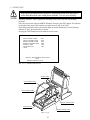
1ST PRINTING JAN. 01
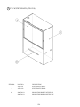
DX Type
Owner’s Manual
SEGA ENTERPRISES, INC. USA
MANUAL NO. 420-6614-01
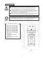
Warranty
Your new Sega Product is covered for a period of 90 days from the date of shipment. This certifies
that the Printed Circuit Boards, Power Supplies and Monitor are to be free of defects in workmanship or materials under normal operating conditions. This also certifies that all Interactive Control
Assemblies are to be free from defects in workmanship and materials under normal operating conditions. No other product in this machine is hereby covered.
Sellers sole liability in the event a warranted part described above fails shall be, at its option, to
replace or repair the defective part during the warranty period. For Warranty claims, contact your
Sega Distributor.
Should the Seller determine, by inspection that the product was caused by Accident, Misuse, Neglect, Alteration, Improper Repair, Installation or Testing, the warranty offered will be null and void.
Under no circumstances is the Seller responsible for any loss of profits, loss of use, or other damages.
This shall be the exclusive written Warranty of the original purchaser expressed in lieu of all other
warranties expressed or implied. Under no circumstance shall it extend beyond the period of time
listed above.
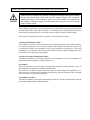
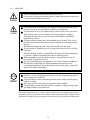
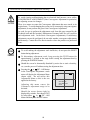
BEFORE USING THE PRODUCT, BE SURE TO READ THE FOLLOWING:
To maintain the safety:
To ensure the safe usage of the product, be sure to read the following before using the product. The following
instructions are intended for the users, operators and the personnel in charge of the operation of the product.
After carefully reading and sufficiently understanding the warning displays and cautions, handle the product
appropriately. Be sure to keep this manual nearby the product or elsewhere convenient for referring to it
when necessary.
Herein, explanations which require special attention are enclosed with dual lines. Depending on the potentially hazardous degrees, the terms of WARNING, CAUTION, etc. are used. Be sure to understand the
contents of the displays before reading the text.
Indicates that mishandling the
product by disregarding this
warning will cause a potentially
hazardous situation which can
result in death or serious injury.
Indicates that mishandling the product
by disregarding this caution will cause
a slight hazardous situation which can
result in personal injury and or material
damage.
For the sage usage of the product, the following pictographs are used:
Indicates “HANDLE WITH CARE.” In order to protect the human body an equipment, this
display is attached to places where the Owner’s Manual and or Service Manual should be referred
to.
Perform work in accordance with the instructions herein stated.
Instructions for work are explained by paying attention to the aspect of accident prevention. Failing to
perform work as per the instructions can cause accidents. In the case where only those who have technical expertise should perform the work to avoid hazardous situation, the instructions herein state that the
serviceman should perform such work.
Be sure to turn off power before working on the machine.
To prevent electric shock, be sure to turn off power before starting the work in which the worker touches
the interior of the product. If the work is to be performed in the power-on status, the Instruction Manual
herein always states to that effect.
Be sure to ground the Earth Terminal (this, however, is not required in the case where a power cord
with earth is used).
This product is equipped with the Earth Terminal. When installing the product, Connect the Earth Terminal to the “accurately grounded indoor earth terminal” by using an earth wire. Unless the product is
grounded appropriately, the user can be subject to electric shock. After performing repair, etc. for the
Control equipment, ensure that the Earth Wire is firmly connected to the Control equipment.
Ensure that the Power Supply used is equipped with an Earth Leakage Breaker.
This product does not incorporate the Earth Leakage Breaker. Using a power supply which is not
equipped with the Earth Leakage Breaker can cause a fire when earth leakage occurs.
Be sure to use fuses which meet the specified rating. (only for the machines which use fuses).
Using fuses exceeding the specified rating can cause a fire and electric shock.
Specification changes (removal of equipment, conversion and addition) not designated by SEGA
are not allowed.
The parts of the product include warning labels for safety, covers for personal protection, etc. It is very
hazardous to operate the product by removing parts and or modifying the circuits. Should doors, lids
and protective parts be damaged or lost, refrain from operating the product, and contact where the
product was purchased from or the office herein stated. SEGA shall not be held responsible for any
accidents, compensation for damage to a third party, resulting from the specifications not designated by
SEGA.
Ensure that the product meets the requirements of appropriate Electrical Specifications.
Before installing the product, check for Electrical Specifications. SEGA products have a nameplate on
which Electrical Specifications are described. Ensure that the product is compatible with the power
supply voltage and frequency requirements of the location. Using any Electrical Specifications different
from the designated Specifications can cause a fire and electric shock.
Install and operate the product in places where appropriate lighting is available, allowing warning
labels to be clearly read.
To ensure safety for the customers, labels and printed instructions describing potentially hazardous
situation are applied to places where accidents can be caused. Ensure that where the product is operated
has sufficient lighting allowing the warnings to be read. If any label is peeled off, apply it again immediately. Please place an order with where the product was purchased from or the office herein stated.
When handling the Monitor, be very careful. (Applies only to the product w/monitor.)
Some of the monitor (TV) parts are subject to high tension voltage. Even after running off power, some
portions are still subject to high tension voltage sometimes. Monitor repair and replacement should be
performed only be those technical personnel who have knowledge of electricity and technical expertise.
Be sure to adjust the monitor (projector) properly. (Applies only to the product w/monitor.)
Do not operate the product leaving on-screen flickering or blurring as it is. Using the product with the
monitor not properly adjusted may cause dizziness or a headache to an operator, a player, or the customers.
When transporting or reselling this product, be sure to attach this manual to the product.
In the case where commercially available monitors and printers are used in this product, only the
contents relating to this product are explained herein. Some commercially available equipment has
functions and reactions not stated in this manual. Read this manual together with the specific Instruction Manual of such equipment.
• Descriptions herein contained may be subject to improvement changes without notice.
• The contents described herein are fully prepared with due care. However, should any question arise or
errors be found, please contact SEGA.
INSPECTIONS IMMEDIATELY AFTER TRANSPORTING THE PRODUCT TO THE LOCATION.
Normally, at the time of shipment, SEGA products are in a status allowing for usage immediately after
transporting to the location. Nevertheless, an irregular situation may occur during transportation. Before
turning on power, check the following points to ensure that the product has been transported in a satisfactory status.
Are there any dented portions or defects (cuts, etc.) on the external surfaces of the cabinet?
Are Casters and Adjusters, damaged?
Do the power supply voltage and frequency requirements meet with those of the location?
Are all wiring connectors correctly and securely connected? Unless connected in the correct direction,
connector connections can not be made accurately. Do not insert connectors forcibly.
Do power cords have cuts and dents?
Do the fuses used meet specified rating? Is the Circuit Protector in an energized status?
Are all accessories available?
Can all Doors and Lids be opened with the Accessory keys? Can Doors and Lids be firmly closed?
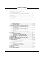
TABLE OF CONTENTS
BEFORE USING THE PRODUCT, BE SURE TO READ THE FOLLOWING:
TABLE OF CONTENTS
INTRODUCTION OF THE OWNER'S MANUAL
1. HANDLING PRECAUTIONS ......................................................................... 1
2. PRECAUTIONS CONCERNING INSTALLATION LOCATION ................. 2 - 3
3. OPERATION .................................................................................................... 4 - 8
4. NAME OF PARTS ............................................................................................ 9
5. ACCESSORIES ................................................................................................ 10 - 12
6. ASSEMBLING AND INSTALLATION .......................................................... 13 - 27
7. PRECAUTIONS TO BE HEEDED WHEN MOVING THE MACHINE ....... 28 - 30
8. CONTENTS OF GAME ................................................................................... 31 - 37
9. EXPLANATION OF TEST AND DATA DISPLAY ...................................... 38 - 60
9 - 1 SWITCH UNIT AND COIN METER .................................................. 39
9 - 2 SYSTEM TEST MODE ....................................................................... 40 - 51
9 - 3 GAME TEST MODE ........................................................................... 52 - 60
10. MAINTENANCE OF CONTROLLER MECHANISM UNIT ........................ 61 - 80
10 - 1 ADJUSTING/REPLACING THE ROLL-DIRECTION
VOLUME CONTROL ......................................................................... 61 - 66
10 - 2 ADJUSTING/REPLACING THE YAW-DIRECTION
VOLUME CONTROL ......................................................................... 67 - 70
10 - 3 GREASING ......................................................................................... 71 - 77
10 - 4 REPLACING THE ACCIDENT AVOIDANCE SYSTEM ............... 78 - 80
11. PROJECTOR .................................................................................................... 81 - 94
11 - 1 CLEANING THE SCREEN ................................................................ 81
11 - 2 ADJUSTMENT OF TOSHIBA PROJECTOR ................................... 82 - 91
11 - 3 ADJUSTMENT OF MITSUBISHI PROJECTOR .............................. 92 - 94
12. COIN SELECTOR ............................................................................................ 95
13. REPLACING THE FLUORESCENT LAMP, AND LAMPS ......................... 96 - 103
14. PERIODIC INSPECTION TABLE .................................................................. 104
15. TROUBLESHOOTING .................................................................................... 105 - 107
15 - 1 TABLE OF TROUBLESHOOTING ................................................. 105 - 106
15 - 2 SYSTEM ERROR MESSAGES ........................................................ 107
16. GAME BOARD ................................................................................................ 108 - 110
16 - 1 REMOVING THE GAME BOARD .................................................. 108 - 109
16 - 2 COMPOSITION OF GAME BOARD ................................................ 110
17. DESIGN RELATED PARTS ........................................................................... 111
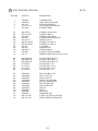
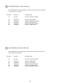
18. PARTS LIST ..................................................................................................... 112 - 156
19. WIRE COLOR CODE TABLE ........................................................................ 157
20. WIRING DIAGRAM ........................................................................................ 158 - 160
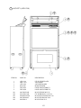
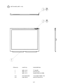
SPECIFICATIONS
Installation space
: 1,315 mm (W) X 2, 845 mm (D)
(51.8 in. X 112.0 in.)
Height
: 2,298 mm (90.4 in.)
Weight
: Approx. 535 kg. (1,179.5 lbs.)
Power, maximum current
: 570 W 6.45 A (AC 110V 50 Hz AREA)
560 W 6.30 A (AC 110V 60 Hz AREA)
555 W 5.70 A (AC 120V 60 Hz AREA)
570 W 3.50 A (AC 220V 50 Hz AREA)
560 W 3.40 A (AC 220V 60 Hz AREA)
560 W 3.35 A (AC 230V 50 Hz AREA)
555 W 3.25 A (AC 230V 60 Hz AREA)
565 W 3.25 A (AC 240V 50 Hz AREA)
555 W 3.15 A (AC 240V 60 Hz AREA)
For TAIWAN (TOSHIBA PROJECTION DISPLAY TYPE)
Power, current
: 575 W 6.75A (MAX.)
360 W 4.10A (MIN.)
For TAIWAN (MITSUBISHI PROJECTION DISPLAY TYPE)
Power, current
: 565 W 6.40A (MAX.)
345 W 3.95A (MIN.)
MONITOR
: 29 TYPE COLOR MONITOR
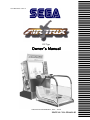
INTRODUCTION OF THE OWNERS MANUAL
This Owner's Manual is intended to provide detailed descriptions together with all
the necessary information covering the general operation of electronic assemblies,
electromechanicals, servicing control, spare parts, etc. as regards the product,
AIR TRIX.
This manual is intended for the owners, personnel and managers in charge of
operation of the product. Operate the product after carefully reading and sufficiently
understanding the instructions. If the product fails to function satisfactorily, nontechnical personnel should under no circumstances touch the internal system. Please
contact where the product was purchased from.
Use of this product is unlikely to cause physical injuries or damages to property. However,
where special attention is required this is indicated by a thick line, the word "IMPORTANT"
and its sign in this manual.
STOP
Indicates that mishandling the product by disregarding this display can cause the
product's intrinsic performance not to be obtained, resulting in malfunctioning.
IMPORTANT
SEGA ENTERPRISES, INC. (U.S.A.)/CUSTOMER SERVICE
45133 Industrial Drive, Fremont, California 94538, U.S.A.
Phone : (415) 701-6580
Fax : (415) 701-6594
DEFINITION OF LOCATION MAINTENANCE MAN AND SERVICEMAN
Non-technical personnel who do not have technical knowledge and expertise should
refrain from performing such work that this manual requires the location's
maintenance man or a serviceman to carry out, or work which is not explained in
this manual. Failing to comply with this instruction can cause a severe accident
such as electric shock.
Ensure that parts replacement, servicing & inspections, and troubleshooting are performed by the
location's maintenance man or the serviceman. It is instructed herein that particularly hazardous
work should be performed by the serviceman who has technical expertise and knowledge.
The location's maintenance man and serviceman are herein defined as follows:
"Location's Maintenance Man" :
Those who have experience in the maintenance of amusement equipment and vending machines,
etc., and also participate in the servicing and control of the equipment through such routine work
as equipment assembly and installation, servicing and inspections, replacement of units and
consumables, etc. within the Amusement Facilities and or locations under the management of the
Owner and Owner's Operators of the product.
Activities of Location's Maintenance Man :
Assembly & installation, servicing & inspections, and replacement of units & consumables as
regards amusement equipment, vending machines, etc.
Serviceman :
Those who participate in the designing, manufacturing, inspections and maintenance service of
the equipment at an amusement equipment manufacturer.
Those who have technical expertise equivalent to that of technical high school graduates as regards electricity, electronics and or mechanical engineering, and daily take part in the servicing &
control and repair of amusement equipment.
Serviceman's Activities :
Assembly & installation and repair & adjustments of electrical, electronic and mechanical parts of
amusement equipment and vending machines.
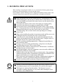
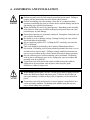
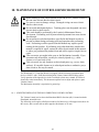
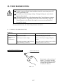
1. HANDLING PRECAUTIONS
When installing or inspecting the machine, be very careful of the following points and pay
attention to ensure that the player can enjoy the game safely.
Non-compliance with the following points or inappropriate handling running counter to the
cautionary matters herein stated can cause personal injury or damage to the machine.
Before performing work, be sure to turn power off. Performing the work
without turning power off can cause an electric shock or short circuit. In the
case work should be performed in the status of power on, this manual always
states to that effect.
To avoid electric shock or short circuit, do not plug in or unplug quickly.
To avoid electric shock, do not plug in or unplug with a wet hand.
Do not expose Power Cords and Earth Wires on the surface, (floor, passage,
etc.). If exposed, the Power Cords and Earth Wires are susceptible to damage.
Damaged cords and wires can cause electric shock or short circuit.
To avoid causing a fire or electric shock, do not put things on or damage
Power Cords.
When or after installing the product, do not unnecessarily pull the power cord.
If damaged, the power cord can cause a fire or electric shock.
In case the power cord is damaged, ask for replacement through where the
product was purchased from or the office herein stated. Using the cord as is
damaged can cause fire, electric shock or leakage.
Be sure to perform grounding appropriately. Inappropriate grounding can
cause an electric shock.
Be sure to use fuses meeting specified rating. Using fuses exceeding the
specified rating can cause a fire or electric shock.
Completely make connector connections for IC BD and others. Insufficient
insertion can cause an electric shock.
Specification changes, removal of equipment, conversion and/or addition, not
designated by SEGA are not permitted.
• Failure to observe this may cause a fire or an electric shock. Non-compliance
with this instruction can have a bad influence upon physical conditions of the
players or the lookers-on, or result in injury during play.
• SEGA shall not be held responsible for damage, compensation for damage to
a third party, caused by specification changes not designated by SEGA.
Be sure to perform periodic maintenance inspections herein stated.
STOP
IMPORTANT
For the IC board circuit inspections, only the logic tester is allowed. The use
of a multiple-purpose tester is not permitted, so be careful in this regard.
The Projector is employed for this machine. The Projector's screen is
susceptible to damage, therefore, be very careful when cleaning the screen.
For details, refer to PROJECTOR.
1
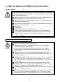
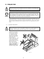
2. PRECAUTIONS CONCERNING INSTALLATION
LOCATION
This product is an indoor game machine. Do not install it outside. Even indoors,
avoid installing in places mentioned below so as not to cause a fire, electric shock,
injury and or malfunctioning.
Places subject to rain or water leakage, or places subject to high humidity in
the proximity of an indoor swimming pool and or shower, etc.
Places subject to direct sunlight, or places subject to high temperatures in the
proximity of heating units, etc.
Places filled with inflammable gas or vicinity of highly inflammable/volatile
chemicals or hazardous matter.
Dusty places.
Sloped surfaces.
Places subject to any type of violent impact.
Vicinity of anti-disaster facilities such as fire exits and fire extinguishers.
The operating (ambient) temperature range is from 5 Celsius to 40 Celsius.
Only in the case a projector is employed, the temperature range is from 5
Celsius to 30 Celsius.
LIMITATIONS OF USAGE REQUIREMENTS
Be sure to check the Electrical Specifications.
Ensure that this product is compatible with the location's power supply,
voltage and frequency requirements.
A plate describing Electrical Specifications is attached to the product.
Non-compliance with the Electrical Specifications can cause a fire and
electric shock.
This product requires the Breaker and Earth Mechanisms as part of the
location facilities. Using them in a manner not independent can cause a fire
and electric shock.
Ensure that the indoor wiring for the power supply is rated at 15A or higher
(AC single phase 100 ~ 120V area), and 10A or higher (AC 220 ~ 240V
area). Non-compliance with the Electrical Specifications can cause a fire and
electric shock.
Be sure to independently use the power supply equipped with the Earth
Leakage Breaker. Using a power supply without the Earth Leakage Breaker
can cause an outbreak of fire when earth leakage occurs.
Putting many loads on one electrical outlet can cause generation of heat and a
fire
resulting from overload.
When using an extension cord, ensure that the cord is rated at 15A or higher
(AC 100 ~ 120V area) and 10A or higher (AC 220 ~ 240V area). Using a
cord rated lower than the specified rating can cause a fire and electric shock.
2
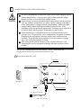
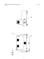
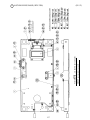
OPERATION AREA
For the operation of this machine, secure a minimum area of 1.9m (W) X 3m
(D). In order to prevent injury resulting from the falling down accident
during game play, be sure to secure the minimum area for operation.
Be sure to provide sufficient space so as to allow this product's ventilation fan
to function efficiently. To avoid machine malfunctioning and a fire, do not
place any obstacles near the ventilation opening.
SEGA shall not be held responsible for damage, compensation for damage to
a third party, resulting from the failure to observe this instruction.
STOP
For transporting the machine into the location's building, the minimum necessary
dimensions of the opening (of doors, etc.) are 1.3m(W) and 1.7m(H).
IMPORTANT
Electric current consumption
MAX. 6.45 A (AC 110V 50 Hz)
MAX. 6.30 A (AC 110V 60 Hz)
MAX. 5.70 A (AC 120V 60 Hz)
MAX. 3.50 A (AC 220V 50 Hz)
MAX. 3.40 A (AC 220V 60 Hz)
MAX. 3.35 A (AC 230V 50 Hz)
MAX. 3.25 A (AC 230V 60 Hz)
MAX. 3.25 A (AC 240V 50 Hz)
MAX. 3.15 A (AC 240V 60 Hz)
For TAIWAN
TOSHIBA projection display
MAX. 6.75 A
MITSUBISHI projection display
MAX. 6.40 A
FIG. 2
3
3. OPERATION
PRECAUTIONS TO BE HEEDED BEFORE STARTING THE OPERATION
To avoid injury and trouble, be sure to constantly give careful attention to the behavior and
manner of the visitors and players.
In order to avoid accidents, check the following before starting the operation:
To ensure maximum safety for the players and the customers, ensure that
where the product is operated has sufficient lighting to allow any warnings to
be read. Operation under insufficient lighting can cause bodily contact with
each other, hitting accident, and or trouble between customers.
Be sure to perform appropriate adjustment of the monitor (projector). For
operation of this machine, do not leave monitor's flickering or deviation as is.
Failure to observe this can have a bad influence upon the players' or the
customers' physical conditions.
It is suggested to ensure a space allowing the players who feel sick while
playing the game to take a rest.
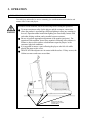
Check if all of the adjusters are in contact with the surface. If they are not, the
Cabinet can move and cause an accident.
Ensure that all of the
Adjusters are in contact
with the floor.
4
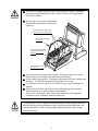
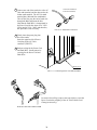
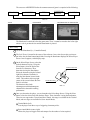
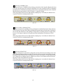
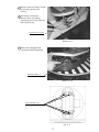
Check to see if hazard preventive parts are damaged or omitted. Operating
the product with the hazard preventive parts as is left in an irregular status
will cause accidents.
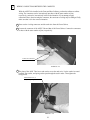
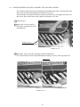
By carrying out a test run, check that the
Skateboard can normally be locked and
unlocked.
Check that the side guard panel
has not cracked or dropped out?
Check that the handrails
do not rattle.
Check that the Skateboard
can normally be locked and
unlocked.
Check that the bellows
have not torn.
Do not put any heavy item on this product. Placing any heavy item on the
product can cause a falling down accident or parts damage.
Do not climb on the product. Climbing on the product can cause falling down
accidents. To check the top portion of the product, use a step.
To avoid electric shock, check to see if door & cover parts are damaged or
omitted.
To avoid electric shock, short circuit and or parts damage, do not put the
following items on or in the periphery of the product.
Flower vases, flowerpots, cups, water tanks, cosmetics, and receptacles/
containers/vessels containing chemicals and water.
To avoid injury, be sure to provide sufficient space by considering the potentially
crowded situation at the installation location. Insufficient installation space can
cause making bodily contact with each other, hitting accidents, and or trouble
between customers.
5
PRECAUTIONS TO BE HEEDED DURING OPERATION (PAYING ATTENTION TO CUSTOMERS)
To avoid injury and trouble, be sure to constantly give careful attention to the behavior and
manner of the visitors and players.
To avoid injury and accidents, those who fall under the following categories
are not allowed to play the game.
• Those who need assistance such as the use of an apparatus when walking.
• Those who have high blood pressure or a heart problem.
• Those who have experienced muscle convulsion or loss of consciousness when
playing video game, etc.
Those who have a trouble in the neck and or spinal cord.
Intoxicated persons.
Pregnant women or those who are in the likelihood of pregnancy.
Persons susceptible to motion sickness.
Persons whose act runs counter to the product's warning displays.
•
•
•
•
•
A player who has never been adversely affected by light stimulus might
experience dizziness or headache depending on his physical condition when
playing the game. Especially, small children can be subject to those
conditions. Caution guardians of small children to keep watch on their
children during play.
Instruct those who feel sick during play to have a medical examination.
To avoid injury resulting from falling down and electric shock due to spilled
drinks, instruct the player not to place heavy items or drinks on the product.
To avoid electric shock and short circuit, do not allow customers to put hands
and fingers or extraneous matter in the openings of the product or small
openings in or around the doors.
To avoid falling down and injury resulting from falling down, immediately
stop the customer's leaning against or climbing on the product, etc.
To avoid electric shock and short circuit, do not allow the customers to
unplug the power plug without a justifiable reason.
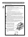
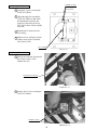
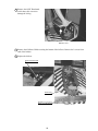
The player should be able to get on
the Skate Board and hold on firmly
to the Safety Bar. To avoid falling
down accidents, instruct those who
are shorter than 130 cm. not to play
the game as the height of the Safety
Bar is approximately 130 cm.
Approx. 130cm
Instruct those who wear high-heeled
shoes to refrain from playing the
game by explaining that playing
game with high-heeled shoes is very
likely to cause potentially hazardous
situation.
6
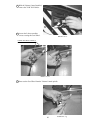
To avoid injury from potential
falling down accidents, be sure to
instruct that only one person is
allowed to play at a time.
Do not allow players to put any
heavy item or beverages on the
product. Falling down items can
cause accidents and spilled
beverages can cause electric shock.
Instruct the player to hold on firmly to the Safety Bar during game. Caution
the customers who are most likely to cause injury by playing without holding
the Safety Bar, for example.
7
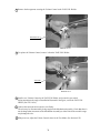
To avoid injury, do not allow
persons other than the player to
access to the Rear Cabi during
game play.
Instruct the player to play by
standing on both feet. Standing
on one leg to play can cause
injury.
Instruct the player not to put
baggages, etc. on the Rear Cabi to
avoid damaging such items.
Regarding this product, the
weight of the player is limited to
150 kg. To avoid machine
damage and injury due to
machine damage, playing by
those who are as heavy as 150 kg.
or heavier is strictly prohibited.
Immediately stop such violent acts as hitting and kicking the product. Such
violent acts can cause parts damage or falling down, resulting in injury due to
fragments and falling down.
8
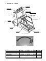
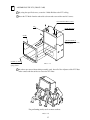
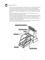
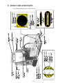
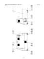
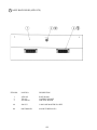
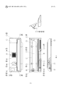
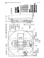
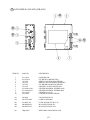
4. NAME OF PARTS
BILLBOARD
FRONT CABI
PTV
50 Type Projector
SWITCH PANEL
COIN CHUTE DOOR
SIDE POP
CASHBOX DOOR
SAFETY BAR
AC UNIT
PTV BASE
REAR CABI
SKATE BOARD
FOOT CONTROLLER
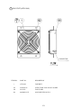
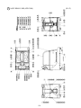
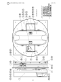
FIG. 4 OVERVIEW
PHOTO 4 ASSY TUBE
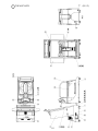
TABLE 4
PTV (50 type Projector)
PTV BASE (FRONT CABI)
BILLBOARD
REAR CABI
When assembled
Width
1,140 mm
1,190 mm
1,128 mm
990 mm
1,740 mm
X Length
X 555 mm
X 1,020 mm
X 440 mm
X 1,620 mm
X 2,740 mm
9
X Height
X 1,670 mm
X 785 mm
X 400 mm
X 1,140 mm
X 2,325 mm
Weight
119 kg
70 kg
20 kg
256 kg
467 kg
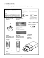
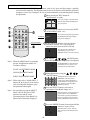
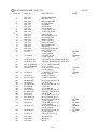
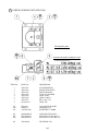
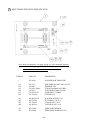
5. ACCESSORIES
When transporting the machine, make sure that the following parts are supplied.
TABLE 5 ACCESSORIES
DESCRIPTION
Part No. (Qty.)
Note
KEY MASTER
220-5576 (2)
For opening/closing
the doors
OWNERS MANUAL
420-6614-01 (1)
Figures
KEY
(2)
For the CASHBOX DOOR
If Part No. has no description, the Number has not been
registered or can not be registered. Such a part may not
be obtainable even if the customer desires to purchase it.
Therefore, ensure that the part is in safekeeping with you.
VOL CONT B-5K OHM
220-5484 (1)
Spare, see Section 10.
The Keys are inside the Coin
Chute Door at the time of
shipment from the factory.
GREASE GUN KH-120
540-0064 (1)
For greasing, see Section 10.
LAMP 6V 3W (WEDGE BULB)
390-5160 (1)
Spare, refer to Section 13.
GREASE ALBAMIA EP-1 400G
(SPECIAL GREASE)
090-0275 (1)
For greasing, see Section 10.
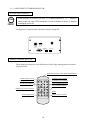
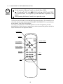
TOSHIBA
Remote Controller used for
adjustment of the projector.
See Section 11.
200-5536(1)
TEST
MODE
WRITING
R
G
B
MITSUBISHI
Remote Controller used for
adjustment of the projector.
See Section 11.
200-5532(1)
CARTON BOX
601-10642 (1)
Used for transporting the
Game Board.
Refer to FIG. 15.
P
POWER
SET
R / B
POSITION
R / G / B
PIC-ADJ
TEST
1
ADJUST
RESET
SELECT
ENTER
8
9
10
CH
R-MUTE G-MUTE B-MUTE
EC
K
SI
DE
-- PICTURE +
MITSUBISHI
One of the above 2 types of
Remote Controllers is used for the
Projector.
The Remote Controller is attached to the Projector at the
time of shipment.
10
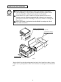
HOW TO USE THE CARTON BOX
STOP
IMPORTANT
When asking for the replacement or repair of the product's Game Board
(SEGA HIKARU), be sure to put the Game Board together with the Shield
Case in a Carton Box. Otherwise, the request is not acceptable.
Put the Shield Case in the Carton Box by paying attention to the correct
direction as per the following instructions and as shown by the instructions
printed on the Carton Box. Handling in an erroneous manner can damage the
Game Board.
Remove the Shield Case Brackets from the Shield Case and put the Shield
Case in the Carton Box.
SHIELD CASE BRACKETS
The shape depends on the type of product.
"CHECK SIDE" Display
CH
EC
K
SI
DE
FILTER BOARD
FIG. 5
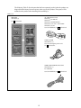
Wrap the Shield Case with the packing material and put it in the Carton Box as shown. Putting
it upside down or packing otherwise in the manner not shown can damage the Game Board and
parts.
11
The following Table 5b lists the parts that had been separately packed when the product was
shipped from the factory but are necessary when you use the product. These parts will be
mounted on the product when installing and assembling it.
TABLE 5 b
SIDE POP
ATR-0003 (2)
see 4 of Section 6.
AC Cable (Power Cord)
600-6724
(1) TAIWAN
600-6729
600-6619 (1) HONG KONG
600-6618 (1) AC 220 ~ 240V AREA
600-6695 (1) USA
Used for installation, see 5 of Section 6.
CORD CLAMP
280-5009-01 (1)
Used for securing the power cord.
see 5 of Section 6.
WIRE HARN EARTH W/LUG M6
600-6664-02 (1)
For TAIWAN.
Used for installation, see 5 of Section 6.
12
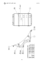
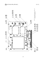
6. ASSEMBLING AND INSTALLATION
Perform assembly work by following the procedure herein stated. Failing to
comply with the instructions can cause electric shock hazard.
Perform assembling as per this manual. Since this is a complex machine,
erroneous assembling can cause an electric shock, machine damage and or not
functioning as per specified performance.
When assembling, be sure to use plural persons. Depending on the assembly
work, there are some cases in which working by one person alone can cause
personal injury or parts damage.
Ensure that connectors are accurately connected. Incomplete connections can
cause electric shock hazard.
Be careful so as not to damage wirings. Damaged wiring can cause electric
shock and short circuit hazards.
Do not carelessly push the PTV. Pushing the PTV carelessly can cause the
PTV to fall down.
This work should be performed by the Location's Maintenance Man or
Serviceman. Performing work by non-technical personnel can cause a severe
accident such as electric shock. Failing to comply with this instruction can
cause a severe accident such as electric shock to the player during operation.
Provide sufficient space so that assembling can be performed. Performing
work in places with narrow space or low ceiling may cause an accident and
assembly work to be difficult.
To perform work safely and avoid serious accident such as the cabinet's
falling down, do not perform work in places where step-like grade
differences, a ditch, or slope exist.
When handling plastic parts, use care. Do not give a shock or apply excessive
load to the fluorescent lamps and plastic parts. Failure to observe this can
cause parts damage, resulting in injury due to fragments, cracks and broken
pieces.
To perform work safely and securely, be sure to prepare a step which is in a
secure and stable condition. Performing work without using the step can
cause violent falling down accidents.
13
When carrying out the assembly work, follow the procedure in the following 7-item sequence:
1
2
3
4
5
6
7
ASSEMBLING THE PTV (FRONT CABI)
WIRING CONNECTIONS BETWEEN THE CABINETS
SECURING IN PLACE (ADJUSTER ADJUSTMENT)
INTALLING THE SIDE POP
POWER SUPPLY, AND EARTH CONNECTION
TURNING POWER ON
ASSEMBLY CHECK
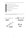
The master key (accessories) in addition to the tools such as a Phillips type screwdriver, Box nut
screwdriver and wrench are required for the assembly work.
24mm
Phillips type screwdriver
(for M4,M5 screw)
7mm
WRENCH (for M16 hexagon bolt)
Box nut screwdriver
(For M4 hexagon nut)
KEY MASTER
14
1
ASSEMBLING THE PTV (FRONT CABI)
1 By using the specified screws, secure the 2 Mask Holders to the PTV ceiling.
2 Insert the TV Mask from the underside as shown and secure with a total of 6 screws.
FLAT HEAD SCREW (2 each)
M4 X 12
PTV
MASK HOLDER
MASK
TRUSS SCREW (2)
M5 X 25, flat washer used,
chrome plated
SCREW (4), black
M5 X 20, w/flat &
spring washers
FIG. 6. 1 a
3 In order to prevent accidents during assembly work, have all of the Adjusters of the PTV Base
make contact with the surfaces to secure the PTV Base.
For performing work, use 4 or more workers.
FIG. 6. 1 b
15
4 Mount the assembled PTV on the PTV Base. After mounting the PTV, move it to the rear part
of the PTV Base. When performing this work, be sure to use 4 or more persons.
(FIG. 6. 1 b)
5 Install Panel Mount Bracket L and R to the front of the PTV by using 2 screws for each of them.
Connecting the 3 connectors
to the connector panel
PANEL MOUNT BRACKET L
FRONT PANEL
TRUSS SCREW (4), black
M5 X 20, flat washer used.
HOLE LID
TRUSS SCREW (3 each), black
M4 X 20
PANEL MOUNT BRACKET R
SCREW (2 each), black
M5 X 20, w/flat & spring washers
SCREW (2 each), black
M4 X 10, w/flat & spring washers
FIG. 6. 1 c
6 Connect the 3 connectors (2 for power supply, 1 for video signal) of the wires already connected
to the PTV Base, to the 3 connectors on the PTV connector panel. The connectors can be
inserted only in the fixed orientation. If you attempt to apply constrained force when inserting
the connector, it may break. Fully make sure that it is in the correct orientation.
The reflection signal connector has the securing screws at the both ends. After connecting,
fasten the screws tightly.
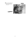
PHOTO 6. 1 a
16
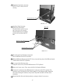
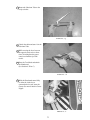
7 PInstall the Front Panel to the front
of PTV. Use the 4 truss screws for
securing.
TRUSS SCREW (4), black
M5 X 20, flat washer used.
PHOTO 6. 1 b
8 Install the 2 Hole Lids to the
HOLE LID
bottom of the Front Panel.
For each of these, use the 2 screws
and 3 truss screws for securing.
Note that different screws must be
used for the Front Panel and PTV
Base.
SCREW (2 each), black
M4 X 10, w/flat & spring washers
TRUSS SCREW (3 each), black
M4 X 20
PHOTO 6. 1 c
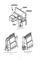
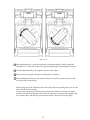
9 This work must be performed by two persons:
Place the Billboard on the PTV top board.
10 With the Billboard shifted toward the PTV Screen, insert the base plate of the Billboard into the
2 mask holders of the PTV Top Board.
11 Use a step for the following works:
Using the 2 truss screws, secure the Billboard to the PTV Top Board.
12 Remove the 2 truss screws. Then, remove the Hole Lid from the Billboard.
13 Connect the 2 connectors in the Billboard to the 2 connectors on the PTV top board. The
connectors can be inserted only in the fixed orientation. If you attempt to apply constrained
force when inserting the connector, it may break. Fully make sure that it is in the correct
orientation.
14 Reinstall the Hole Lid to the initial position by securing it with the 2 truss screws.
17
TRUSS SCREW (2)
M5 X 40, chrome plated
BILLBOARD
TRUSS SCREW (2)
M4 X 8, chrome plated
HOLE LID
Connect the 2 Connectors.
FIG. 6. 1 d
When performing work,
be sure to use a step.
For performing work, use 2 workers.
FIG. 6. 1 f
FIG. 6. 1 e
18
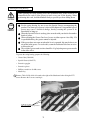
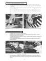
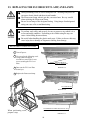
2
WIRING CONNECTIONS BETWEEN THE CABINETS
With the ASSY Tube installed to the Front and Rear Cabinets, perform the cabinet-to-cabinet
wiring. The connectors can be inserted only into those with the same number of pins,
respectively, and can be inserted only in the fixed orientation. If you attempt to apply
constrained force when inserting the connector, the connector or wiring may be damaged. Fully
make sure that it is in the correct orientation.
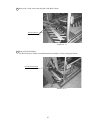
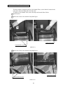
1 Draw out the 6 wiring connectors and the earth wire from the Front Cabinet.
2 Connect the connector of the ASSY Tube and that of the Front Cabinet. Connect the connectors
to those with the same number of pins, respectively.
Connect the Connector.
PHOTO 6. 2 a
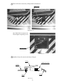
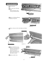
3 The plate of the ASSY Tube has a stud used to secure the earth wire. Let the earth wire round
terminal, flat washer, and spring washer pass through the stud in order. Then tighten the
hexagon nut.
HEXAGON NUT (1)
M4, flat & spring washers used.
PHOTO 6. 2 b
19
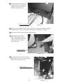
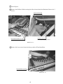
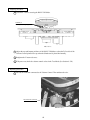
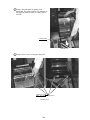
4 Install the plate of the ASSY Tube
to the front of the Front Cabinet by
using the 4 truss screws. Do not
pinch the wiring at this time.
TRUSS SCREW (4), black
M4 X 20
PHOTO 6. 2 c
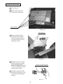
5 Locate the Front and Rear Cabinets close to each other. If you jerk the wiring by applying
constrained force (in order to connect the connectors), the wiring may be damaged.
6 Draw out the 6 wiring connectors from the Rear Cabinet.
7 Connect the connector of the
ASSY Tube and that of the Rear
Cabinet. Connect the connectors to
those with the same number of
pins, respectively.
Connect the Connector.
PHOTO 6. 2 d
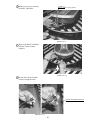
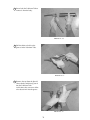
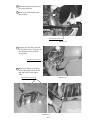
8 Install the plate of the ASSY Tube to the
Rear Cabinet. Use the 4 screws for securing.
Be careful not to pinch the wiring.
SCREW (4), black
M4 X 10, w/flat & spring washers
20
PHOTO 6. 2 e
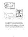
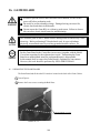
3
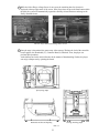
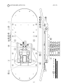
SECURING IN PLACE (ADJUSTER ADJUSTMENT)
Make sure that all of the adjusters are in contact with the floor. If they are not, the
cabinet can move and cause an accident.
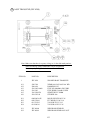
This machine has 8 casters (4 for the Front Cabinet, 4 for the Rear Cabinet) and 8 adjusters (4
for the Front Cabinet, 4 for the Rear Cabinet). (FIG. 6. 3 a) When the installation position is
determined, cause the adjusters to come into contact with the floor directly, make adjustments in
a manner so that the casters will be raised approximately 5mm. from the floor and make sure
that the machine position is level.
CASTER (8 in total)
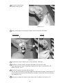
1 Move the machine to the installation
position.
To ensure the safe operation of the
product, provide sufficient space by
adequately keeping the product away
from wall surfaces and other cabinets.
2 Cause all of the adjusters to make
contact with the floor. By using a
wrench, make adjustments in the
height of the adjusters to ensure that
the machine's position is level.
3 After making adjustments, fasten the
adjuster nut upward and secure the
height of the adjuster. (FIG. 6. 3 b)
ADJUSTER (10 in total)
FIG. 6. 3 a BOTTOM VIEW
ADJUSTER
CASTER
FASTEN UPWARD.
Approx.5mm
ADJUSTER
FIG. 6. 3 b ADJUSTER
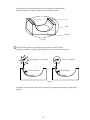
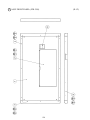
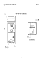
10cm
FIG. 6. 3 c
Refer to this Fig. (Scale:1/100) for the
layout of the place of installation.
Approx.
14cm
FIG. 6. 3 d
Provide sufficient space so as to allow for
ventilation by the ventilation fan.
Provide space approximately 14cm. between the
Front Cabinet and the Rear Cabinet.
21
4
INTALLING THE SIDE POP
FIG. 6. 4
22
5
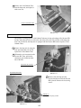
POWER SUPPLY, AND EARTH CONNECTION
Be sure to independently use the power supply socket outlet equipped with an
Earth Leakage Breaker. Using a power supply without an Earth Leakage
Breaker can cause a fire when electric leakage occurs.
Ensure that the "accurately grounded indoor earth terminal" and the earth wire
cable are available (except in the case where a power cord plug with earth is
used). This product is equipped with the earth terminal. Connect the earth
terminal and the indoor earth terminal with the prepared cable. If the
grounding work is not performed appropriately, customers can be subjected to
an electric shock, and the product's functioning may not be stable.
Ensure that the power cord and earth wire are not exposed on the surface
(passage, etc.). If exposed, they can be caught and are susceptible to damage.
If damaged, the cord and wire can cause electric shock and short circuit
accidents. Ensure that the wiring position is not in the customer's passage
way or the wiring has protective covering.
After wiring power cord on the floor, be sure to protect the power cord.
Exposed power cord is susceptible to damage and causes an electric shock
accident.
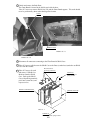
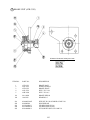
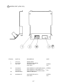
The AC Unit is mounted on the side of the machine. The AC Unit has Main SW,
Circuit Protector and the Inlet which connects the Power Cord.
1 Ensure that the Main SW is OFF.
MAIN SW
CIRCUIT PROTECTOR
Main SW off
INLET
EARTH TERMINAL
Connect with the
indoor earth terminal.
AC Cable (Power Cord)
FIG. 6. 5 a AC unit
23
2 Connect one end of the earth wire to the AC
Unit earth terminal, and the other end to the
indoor earth terminal. The AC Unit earth
terminal has a Bolt and Nut combination.
Take off the Nut, pass the end of earth wire
through the Bolt, and fasten the Nut.
Note that the Earth Wire is incorporated in
the Power Cord for the Areas of AC 120V
(USA) and AC 220 ~ 240V, and therefore,
this procedure is not necessary.
Connect the Earth Wire
to the Earth Terminal.
FIG. 6. 5 b Earth Wire Connection
3 Firmly insert the power plug into
the socket outlet.
Insert the opposite side of Power
Cord plug to the AC Unit's
connector ("INLET").
4 Perform wiring for the Power Cord
and Earth Wire. Install protective
covering for the Power Cord and
Earth Wire.
Wiring Cover
FIG. 6. 5 c Connecting Power Cord and Earth Wire
In case the Power Plug is apt to come out of place, secure the
Power Cord to the periphery of the AC Unit with the Cord
Clamp (an accessory).
HOW TO USE THE CORD CLAMP
24
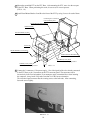
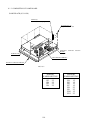
6
TURNING POWER ON
Turn on the AC unit main switch to power on the machine. Once it is powered on, the Billboard
fluorescent lamp and Slim Tube light up. After several seconds, the screen changes to the
Advertise Screen, which is in the wait-for-guest mode. At the same time, the loudspeakers to the
left and right of the Switch Panel and the super woofer located at the bottom of the cache box
door output voices. If No Voice Output has been set, no voices are output during the Advertise
Mode.
The four Cold-Cathode Tubes to the left and right of the Rear Cabinet light up or go out,
depending on the status on the Advertise Screen.
Even after being powered off, this product retains data about the number of credits and ranking.
It does not retain the Factional Number of Coins (i.e., the number of coins put into the slot does
not reach one credit) or Bonus Adder Count data. Thus, if you power on the machine after
powering it off when the available number of credits for playing a game has remained, powering
on machine causes the Start button to blink.
The Skateboard is unlocked when a game starts. Thus, it cannot be moved to the left or right
unless a coin is put into the slot and the Start button is pressed.
Billboard's fluorescent lamp and Slim lamp
Always lit
On-screen images are outputted.
Start button.
Sound is emitted.
Skateboard Lock
Cold-Cathode Tube On/Off
FIG. 6. 6
25
7
ASSEMBLING CHECK
In the TEST MODE, ensure that the assembly has been made correctly and IC BD. is
satisfactory (refer to Section 9).
In the test mode, perform the following test:
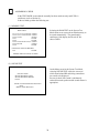
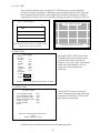
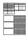
(1) MEMORY TEST
RAM TEST
IC15 IC16 IC17S IC18S
IC22 IC23 IC24S IC25S
IC28 IC29S
IC41
IC42
IC44 IC45S IC46 IC47S
IC91S IC92S
IC98
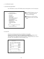
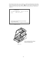
Selecting the RAM TEST on the System Test
Mode menu screen causes the on-board memory to
be tested automatically. The game board is
satisfactory if the display beside each IC No.
shows GOOD.
GOOD
GOOD
GOOD
GOOD
GOOD
GOOD
GOOD
GOOD
OPTIONAL SOUND BOARD:
IC2
GOOD
PRESS TEST BUTTON TO EXIT
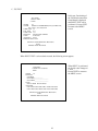
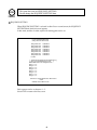
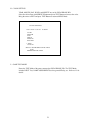
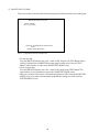
(2) SOUND TEST
On the Menu screen in the System Test Mode,
selecting SOUND TEST causes the screen (on
which sound related BD and wiring connections
are tested) to be displayed.
Be sure to check if the sound is satisfactorily
emitted from each speaker and the sound volume is
appropriate.
SOUND TEST
MAIN SPEAKER LEFT
MAIN SPEAKER RIGHT
> EXIT
SELECT WITH SERVICE BUTTON
AND
PRESS TEST BUTTON
26
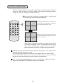
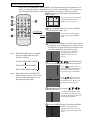
(3) C.R.T. TEST
In the System Test Mode menu, selecting C.R.T. TEST allows the screen (on which the
projector is tested) to be displayed. Although the projector adjustments have been made at the
time of shipment from the factory, make judgment as to whether an adjustment is needed by
watching the test mode screen. If it is necessary, adjust the projector by referring to Section 11.
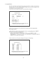
C.R.T. TEST PAGE#1
0
31
RED
GREEN
BLUE
WHITE
PRESS SERVICE BUTTON TO ANOTHER PAGE
PRESS TEST BUTTON TO EXIT
12345678901234567890123456789
12345678901234567890123456789
12345678901234567890123456789
C.R.T. TEST PAGE#2
12345678901234567890123456789
12345678901234567890123456789
12345678901234567890123456789
12345678901234567890123456789
12345678901234567890123456789
12345678901234567890123456789
12345678901234567890123456789
12345678901234567890123456789
12345678901234567890123456789
12345678901234567890123456789
12345678901234567890123456789
12345678901234567890123456789
12345678901234567890123456789
12345678901234567890123456789
12345678901234567890123456789
12345678901234567890123456789
PRESS SERVICE BUTTON TO ANOTHER PAGE
12345678901234567890123456789
PRESS TEST BUTTON TO EXIT
12345678901234567890123456789
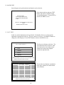
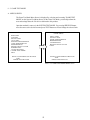
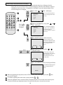
(4) INPUT TEST
INPUT
NODE
BUTTON
START
LEFT
RIGHT
UP
DOWN
SERVICE
TEST
VOLUME
YAW 80
LEFT
TEST
1/1
Selecting the INPUT TEST on the Game
Test Mode menu screen causes the screen
(on which each switch is tested) to be
displayed. Press each switch. If the display
beside each switch indicates "ON," the
switch and wiring connections are
satisfactory.
OFF
OFF
OFF
OFF
OFF
OFF
OFF
RIGHT
ROLL 80
LEFT
RIGHT
PRESS TEST AND SERVICE BUTTON TO EXIT
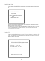
(5) OUTPUT TEST
OUTPUT TEST
LEFT UPEER LAMP
LEFT LOWER LAMP
RIGHT UPEER LAMP
RIGHT LOWER LAMP
START LAMP
LOCK MECHA
> EXIT
The OUTPUT Test menu screen in the
Game Test Mode allows Lamps and wiring
connections to be checked. Check if each
lamp lights up satisfactorily.
OFF
OFF
OFF
OFF
OFF
OFF
SELECT WITH SERVICE BUTTON
AND
PRESS TEST BUTTON
Perform the above inspections also at the time of monthly inspections.
27
7. PRECAUTIONS TO BE HEEDED WHEN MOVING THE MACHINE
When moving the machine, be sure to unplug the power plug. Moving the
machine with the plug as is inserted can damage the power cord and cause fire
and electric shock hazards.
When moving the machine on the floor, retract the Adjusters and ensure that
Casters make contact with the floor. During transportation, pay careful
attention so that Casters do not tread power cords and earth wires. Damaging
the power cords can cause electric shock and short circuit hazards.
When lifting the cabinet, be sure to hold the grip portions or bottom part.
Lifting the cabinet by holding other portions can damage parts and installation
portions due to the empty weight of the cabinet, and cause personal injury.
When transporting the product in places with step-like differences in grade,
disassemble into each unit before transporting. Lifting up the product in an
attempt to cross the step-like differences in an as is assembled condition may
damage the unit's joining portions and cause a personal injury resulting from
damage.
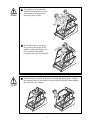
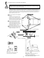
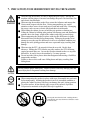
When moving the PTV, do not push it from the rear side. Push it from
sideways. Pushing the PTV from the rear side can have the PTV fall down,
causing personal injury etc. In case the floor has slanted surfaces or step-like
differences, be sure to move the machine by 2 or more persons.
Do not insert the fork to places other than designated when using a Forklift to
transport the machine.
Failure to observe this could cause falling down and injury resulting from
falling down.
Do not push the plastic made parts. Failure to observe this may damage parts and
cause injury due to fragments resulting from damage.
STOP
IMPORTANT
When transporting the product in places with steps, disassemble into each unit
before transporting. Inclining the product in an as is assembled condition or
placing the cabinet in places with steps can damage the unit's joining portions.
To protect surface, do not directly apply a rope to the surfaces of product.
Use protective materials to the places the rope is applied to.
Do not push PTV from the back. Pushing the PTV
from the back can cause the PTV to fall down. Push
it from the side.
28
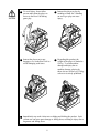
On level surfaces, move the machine by causing
the Casters to make contact with the surfaces.
FIG. 7 a
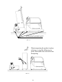
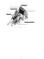
When transporting the product in places
with steps or step-like differences in
grade, disassemble into each unit before
transporting.
GRIP
FIG. 7 b
29
The pop is apt to break,
and pay attention to it.
Do not hold or press these hatched
parts to move the product.
Hold the grip to move.
Plastic made parts
Do not to damage the ASSY TUBE.
Hold the metal parts to move.
FIG. 7 c
30
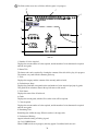
8. CONTENTS OF GAME
The following explanations apply to the case the product is functioning satisfactorily. Should
there be any moves different from the following contents, some sort of faults may have
occurred. Immediately look into the cause of the fault and eliminate the cause thereof to ensure
satisfactory operation.
While the machine is being energized, the Billboard's fluorescent lamp and Slim Tube
continuously stay lit up.
The left and right Rear Cabinets light up or go out, depending on the status on the Advertise
Screen.
The screen displays demonstration video images and ranking data.
The loudspeakers to the left and right of the Switch Panel and the super woofer located at the
bottom of the cache box door output voices.
With the settings in the Test Mode, you can select whether to output voices in the Advertise
Mode.
Billboard's fluorescent lamp and Slim lamp
Always lit
On-screen images are outputted.
Start button.
Sound is emitted.
Coin Inlet
Skateboard Lock
Cold-Cathode Tube On/Off
FIG. 8 b
31
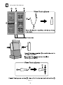
The on-screen ADVERTISE before the commencement of game is comprised of the following:
SEGA ROGO
ADVERTISE
TITLE
DESCRIPTION OF
OPERATION
RANKING
FIG. 8 b
TITLE
ADVERTISE
DESCRIPTION OF OPERATION
The Skateboard is unlocked before the game starts. Thus, it cannot be moved to the left or right
unless a coin is put into the slot and the Start button is pressed.
How to Play
1 Get on the Skateboard (i.e., Controller Board).
2 The Coin Tower is located in the center of the enclosure. Once coins for one play session are
put in the slot, the Start button lamp blinks. Pressing the Start button displays the Select Player
Screen. Once it appears, credit display stops.
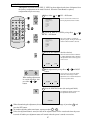
3 On the Select Player Screen, select the
desired character for play. Using the
Select button, select the desired one
from the five characters. Then,
determine it using the Start button.
Select the character using the left and
right Select buttons. Determine it
using the Start button, located in the
center. The numbers at the top right
corner of the screen indicate the time
limit for selection.
The characters have both
advantageous and disadvantageous
characteristics about their running
performance.
SELECT BUTTON
START BUTTON
FIG. 8 c
4 Once you determine the player, you are brought to the Select Stage Screen. Using the Select
button, select the desired one from the three stages. Then, determine it using the Start button.
There are two stage modes: Tutorial and Score Attack. One stage is available for the Tutorial
Mode, and two stages are available for Score Attack Modes.
Tutorial Mode (left)
Lets the player learn three ways of triggering elementary tricks.
Score Attack Mode (center, right)
Allows the player to trigger tricks and compete for the number of coins acquired.
32
5 While the Select Player or Stage Screen is on-screen, the remaining time for selection is
displayed at the top right corner of the screen. If the player does not press the Start button within
the time, the system will automatically regard the currently selected character and stage as the
finally determined ones.
FIG. 8 d Player Select screen, Stage Select screen
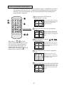
6 Once the stage is determined, the game starts. After message "Release the lock of the controller
board" appears, the Skateboard (i.e., Controller Board) is unlocked. Then, the player can
perform Spin operations.
At the bottom, turn in the desired direction in the manner of skateboarding. Further, the player
can enjoy a sharper turn by spinning the board.
Spin (swing) Input
Backward and forward inputting
Curving (inclining) Input
FIG. 8 e
33
At the bottom, turn in the desired direction in the manner of skateboarding.
Further, the player can enjoy a sharper turn by spinning the board.
Lip
Ramp
Bottom
FIG. 8 f
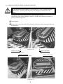
7 The aim of this game is to get a high score by achieving a trick in the air.
The player can achieve a trick by inputting data to the Controller Board on the lip.
A trick appears -- Acceleration
Succeed in kicking
Totters -- Lose Speed
Fail in kicking
FIG. 8 g
In addition, the player can achieve tricks separately by inputting different types of data during
kicking.
34
"Achieving a COMBO Trick"
The player can cause a COMBO trick by kicking on the back of the Controller Board at the front
of the lip. Once the player can succeed in the kicking, he or she can link the tricks by reinputting
the data in the air. The knack of acquiring proficiency is to input data moderately to the Controller
Board, taking account into the his or her speed (i.e., duration of jump).
If the player inputs the first item of data after the jumping step is exceeded, the character loses
its speed. The advice is displayed at this time.
FIG. 8 h
"How to Achieve a Spinning Trick"
The player can generate a spinning trick by spinning the Controller Board at the front of the lip.
Once the player succeeds in the kicking, keeping the position achieved at the time of kicking in
the air causes the character to start spinning. A longer time of spinning results in a higher score;
however, if the player continues to keep the position at landing time, the character will fall
down.
If the player inputs the first item of data after the jumping step is exceeded, the character loses
its speed. The advice is displayed at this time.
FIG. 8 i
"Achieving a Grind Trick"
The player can generate a grind trick by diagonally entering the bottom and kicking on the front
of the Controller Board at the front of the lip. Once the player succeeds in the kicking, keeping
the position achieved at the time of kicking in the air causes the character to start skating on the
lip. A longer time of skating results in a higher score; however, the character falls down unless
the player restores the board before it totters.
If the player inputs the first item of data after the jumping step is exceeded, the character loses
its speed. The advice is displayed at this time.
FIG. 8 j
35
8 The fields on the screen are as follows while the game is in progress:
E
F
G
TIME
GRADE
@
C
29.14
130/160COINS
Bonus
GRIND 15m
A
GOOD
SPIN TRICK
B
C
1096
C
¤COOL COMBO BONUS
+
11COINS
D
H
+
I
TAIL GRAB
FIG. 8 k
1: Number of Coins Acquired
Displays the current number of coins acquired, and the number of coins that must be acquired
until the next grade.
2: Bonus Title
The bonus coins can be acquired by clearing the contents of the title while a play is in progress.
The contents vary each time the character grades up.
3: Trick
Displays the category and the contents of the currently achieved trick.
4: Evaluation per Jump
Displays the grade that corresponds to the total number of coins acquired per jump by grade.
This grade has no relation to that on the top left corner of the screen.
5: Trick Name
Displays the name of the sill achieved.
6: Grade
Displays the current grade, which will rise when coins will be acquired.
7: Coins Acquired
Displays the current number of coins acquired, and the number of coins that must be acquired
until the next grade.
8: Remaining Time
Remaining time within the stage. When it reaches 0, the stage ends.
9: Evaluation of Kicking
Appears when the timing of kicking is good.
10: Cool COMBO Bonus
When COMBO tricks are in progress, this may appear if combined tricks are cool.
36
9 When the time expires, the game is over.
10 After the game ends, lock the Skateboard (i.e., Controller Board).
11 If the player establishes a high score, the final evaluation will be followed by a screen letting
him or her enter the three initials. In response to the prompt, the player should select the
characters while scrolling them with the Select button. Then, determine the characters one by
one using the Start button. Once all the three are determined, the player should locate the cursor
at END and press the Start button for determination.
12 In the Score Attack Mode, the password appears along with the Game Over display.
Record this password. The player can be registered for the World Ranking by sending it to the
home page of this game. Using the Start button, the player can skip this screen, which remains
on-screen for several tens of seconds.
Home page address: http://www.hitmaker.co.jp/AIRTRIX
By making the settings in the Test Mode, you can select whether to display the password.
37
9. EXPLANATION OF TEST AND DATA DISPLAY
By operating the switch unit, periodically perform the tests and data check. When installing the
machine initially or collecting cash, or when the machine does not function correctly, perform
checking in accordance with the explanations given in this section.
The following shows tests and modes that should be utilized as applicable.
SEGA HIKARU GAME BOARD is used for the product. The system of this game board
allows another game to be played by replacing the ROM Board Case mounted on the SEGA
HIKARU CASE. As such, the Test Mode of this system consists of the System Test Mode for
the system to execute SELF-TEST, COIN ASSIGNMENTS, etc. used in common for the
machines employing the SEGA HIKARU BOARD, and the Game Test Mode for the specific
product to execute Input/Output test for the operation equipment, difficulty setting, etc.
STOP
IMPORTANT
The contents of settings changed in the TEST mode are stored when the test
mode is finished from EXIT in the menu mode. If the power is turned off
before the TEST mode is finished, the contents of setting change become
ineffective.
Executing "BACKUP DATA CLEAR" in the SYSTEM TEST MODE does
not clear the BOOKKEEPING data in the GAME TEST mode.
Entering the TEST mode clears fractional number of coins less than one credit
and BONUS ADDER data.
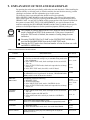
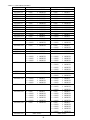
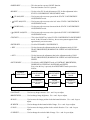
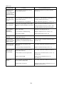
TABLE 9 EXPLANATION OF TEST MODE
ITEMS
DESCRIPTION
INSTALLATION OF
MACHINE
When the machine is installed, perform the following:
1. Check to see that each setting is as per standard setting made at the
time of shipment.
2. In the INPUT TEST mode, check such input devices as each SW,
V.R., etc.
3. In the OUTPUT TEST mode, check such output devices as lamps,
motors, etc.
4. In the SELF-TEST mode, check ICs on the IC Board.
MEMORY
Choose RAM TEST and ROMBD TEST in the MENU mode to allow
the MEMORY test to be performed. In this test, PROGRAM RAMs,
ROMs, and ICs on the IC Board are checked.
PERIODIC
SERVICING
Periodically perform the following:
1. MEMORY TEST
2. Ascertain each setting.
3. In the INPUT TEST mode, test the CONTROL device
4. In the OUTPUT TEST mode, check such output devices as lamps,
motors, etc.
CONTROL
SYSTEM
1. In the INPUT TEST mode, check such input devices as each SW,
V.R., etc.
2. Adjust or replace each SW and VR.
3. If the problem can not be solved yet, check the CONTROL's
moves.
REFERENCE
SECTIONS
9-2 F,G, 9-3 D
9-2 C, 9-3 B
9-3 C
9-2 B,J
9-2 B,J
9-2 B,J
9-2 F,G, 9-3 D
9-2 C, 9-3 B
9-3 C
9-2 C, 9-3 B
9-3 F, 10
MONITOR
In the MONITOR ADJUSTMENT mode,
check to see if the PROJECTOR adjustment is appropriately made.
9-2 E
12
IC BOARD
1. MEMORY TEST
2. In the SOUND TEST mode, check the sound related ROMs.
9-2 B,J
9-2 D
DATA CHECK
Check such data as game play time and histogram to adjust the
difficulty level, etc.
9-2 H, 9-3 E
38
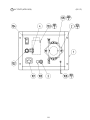
9 - 1 SWITCH UNIT AND COIN METER
Never touch places other than those specified. Touching places not specified can
cause electric shock and short circuit hazards.
STOP
IMPORTANT
Adjust to the optimum sound volume by considering the environmental
requirements of the installation location.
If the COIN METER and the game board are electrically disconnected, game
play is not possible.
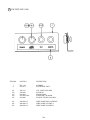
SOUND VOLUME
For Super Woofer
SWITCH UNIT
Open the coin chute door, and the switch unit
shown will appear.
The functioning of each SW is as follows:
TEST BUTTON
SERVICE BUTTON
SOUND VOLUME
For Right/Left Speakers.
FIG. 9. 1 a SWITCH UNIT
SOUND VOLUME CONTROL :
Adjusts the Right/Left Speakers.
SPEAKER
SOUND VOLUME CONTROL :
Adjusts the Super Woofer .
SUPER WOOFER
TEST BUTTON :
For the handling of the test button, refer to
the following pages.
Gives credits without registering on the coin
meter.
TEST
SERVICE BUTTON :
SERVICE
COIN METER
Open the Cashbox Door by using the key to have the Coin
Meter appear underneath the Cashbox.
COIN METER
FIG. 9. 1 b
39
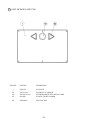
9 - 2 SYSTEM TEST MODE
A. SYSTEM TEST MODE MENU
Press TEST Button to enter the TEST MODE, and the following Menu screen will be displayed.
Press SERVICE Button to move the
arrow (>) to the desired item and
select with TEST Button.
SYSTEM MENU
XXXXXXXXX VERSION
RAM TEST
JVS TEST
SOUND TEST
C.R.T. TEST
SYSTEM ASSIGNMENTS
COIN ASSIGNMENTS
BOOKKEEPING
BACKUP DATA CLEAR
ROMBD TEST
CLOCK SETTING
GAME TEST MODE
> EXIT
Bring the arrow to EXIT and press
TEST Button to return to the GAME
Mode.
SELECT WITH SERVICE BUTTON
AND
PRESS TEST BUTTON
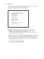
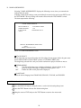
B. RAM TEST
This allows for checking the functioning of the RAM on the Game BD.
In this test, IC's are checked in every row. During the test, "CHECKING" is displayed at the
right-hand side of the screen. "BAD" is indicated for irregular RAMs, if any.
Upon finishing the test, "PRESS TEST BUTTON TO EXIT" is displayed on the lower center of
the monitor. Press TEST Button to return to the MENU screen.
RAM TEST
IC15 IC16 IC17S IC18S GOOD
IC22 IC23 IC24S IC25S GOOD
IC28 IC29S
GOOD
IC41
GOOD
IC42
GOOD
IC44 IC45S IC46 IC47S GOOD
IC91S IC92S
GOOD
IC98
GOOD
OPTIONAL SOUND BOARD:
IC2
GOOD
PRESS TEST BUTTON TO EXIT
40
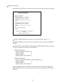
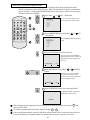
C. JVS TEST
JVS TEST
INPUT TEST
> EXIT
NODE
1/1
NAME
SEGA ENTERPRISES,LTD.;I/O BD JVS;
837-13551 ;Ver1.00;98/10
CMD VER 1.1
JVS VER
2.0
COM VER 1.0
SWITCH
2 PLAYERS 13BITS
COIN
2 SLOTS
ANALOG 8CH
DRIVER OUT 6CH
In this test, Functioning of
the I/O Board connected to
Game Board is displayed
and INPUT TEST can be
performed. Execute EXIT
to return to the MENU
screen.
SELECT WITH SERVICE BUTTON
AND
PRESS TEST BUTTON
When INPUT TEST is selected and executed, the following screen appears.
JVS TEST
> DISPLAY CONFIG
EXIT
NODE
1/1
SWITCH
SYSTEM _ _ _ _ _ _ _ _
PLAYER1 _ _ _ _ _ _ _ _ _ _ _ _ _
PLAYER2 _ _ _ _ _ _ _ _ _ _ _ _ _
COIN
SLOT1 0000 SLOT2 8000
ANALOG
CH1 6300 CH2 5A00 CH3 7D00 CH4 8100
CH5 1F00 CH6 1D00 CH7 1F00 CH8 2000
SELECT WITH SERVICE BUTTON
AND
PRESS TEST BUTTON
41
When INPUT is performed,
the Switch value changes to
1 from _.
Execute EXIT to return to
the MENU screen.
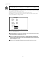
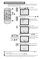
D. SOUND TEST
Sound Output can be performed and each Speaker can be checked.
Select the desired item and press TEST
Button, and sound is emitted from the
corresponding Speaker. Execute EXIT to
return to the MENU screen.
SOUND TEST
MAIN SPEAKER LEFT
MAIN SPEAKER RIGHT
> EXIT
SELECT WITH SERVICE BUTTON
AND
PRESS TEST BUTTON
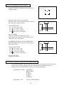
E. C.R.T. TEST
In this test, monitor adjustment can be performed. Periodically check to see if the monitor
adjustment is appropriate in this test. This test consists of 2 screens. Use SERVICE Button to
change the screen displayed. Press TEST Button to return to the MENU screen.
C.R.T. TEST PAGE#1
0
31
RED
GREEN
The first screen displays color bars. The
color adjustment can be checked. Each
of red, green, blue is the darkest at the
leftmost end, and becomes brighter
towards the right-hand end.
BLUE
WHITE
PRESS SERVICE BUTTON TO ANOTHER PAGE
PRESS TEST BUTTON TO EXIT
12345678901234567890123456789
12345678901234567890123456789
12345678901234567890123456789
12345678901234567890123456789
C.R.T. TEST PAGE#2
12345678901234567890123456789
12345678901234567890123456789
12345678901234567890123456789
12345678901234567890123456789
12345678901234567890123456789
12345678901234567890123456789
12345678901234567890123456789
12345678901234567890123456789
12345678901234567890123456789
12345678901234567890123456789
12345678901234567890123456789
12345678901234567890123456789
12345678901234567890123456789
12345678901234567890123456789
12345678901234567890123456789
PRESS SERVICE BUTTON TO ANOTHER PAGE
12345678901234567890123456789
12345678901234567890123456789
PRESS TEST BUTTON TO EXIT
42
The second screen displays crosshatches.
In this page, monitor size and deviation
can be checked.
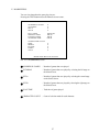
F. SYSTEM ASSIGNMENTS
The settings of cabinet and board can be changed. Set each item suitable to the connected
cabinet. Use the setting as is the time of shipment except for ADVERTISE SOUND.
SYSTEM ASSIGNMENTS
CABINET TYPE
1PLAYER
ADVERTISE SOUND ON
MONITOR TYPE
HORIZONTAL
DISPLAY MODE
AUTOSCAN
SERVICE TYPE
COMMON
> EXIT
SELECT WITH SERVICE BUTTON
AND
PRESS TEST BUTTON
CABINET TYPE specifies Control Panel and number of Coin Chute. The number of Player
displayed in BOOKKEEPING varies in accordance with the value here.
ADVERTISE SOUND is used for settings of emitting sound during ADVERTISE.
MONITOR TYPE sets the on-screen display to the positional direction of monitor (HORIZONTAL or VERTICAL). If set to VERTICAL, the on-screen display for the test mode is
vertically positioned in accordance with the setting.
DISPLAY MODE sets the monitor's display frequency. In this mode, if other than
AUTOSCAN is selected and EXIT is executed, the display frequency is changed to the
selected setting.
SERVICE TYPE sets the functioning of when the Service Button is pressed, in case that
several Service Buttons exist.
• INDIVIDUAL
By pressing Service Button, Service credit can be obtained for the Player corresponding
to the Service Button pressed.
• COMMON
By pressing any Service Button, Service credit can be obtained for all Players.
43
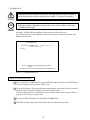
G. COIN ASSIGNMENTS
In this mode, the setting of incremental credit increase as against coin insertion can be changed.
This test consists of 3 screens, and the following is the first screen.
The setting done in the first screen will be stored when exited.
COIN ASSIGNMENTS
COIN CHUTE TYPE
COMMON
COIN/CREDIT SETTING
#1
COIN CHUTE #1
1COIN 1CREDIT
COIN CHUTE #2
1COIN 1CREDIT
MANUAL SETTING
SEQUENCE SETTING
> EXIT
SELECT WITH SERVICE BUTTON
AND
PRESS TEST BUTTON
COIN CHUTE TYPE sets whether Coin Chute is used in common by all players or
separately allocated to each player in case 2 or more Coin Chutes are incorporated.
COMMON: This setting is for common use by plural players.
INDIVIDUAL: As each player uses an independent coin chute, setting to INDIVIDUAL
causes COIN CHUTE #2 to be disappeared.
COIN/CREDT SETTING is set when using one of the existing 26 settings or FREE PLAY.
The selected coin rates in the COIN/CREDIT SETTING are displayed below COIN CHUTE
#1 and COIN CHUTE #2. If you wish to set a coin rate rather than to select from the
existing setting, select MANUAL SETTING. The display next to COIN/CREDIT SETTING
indicates "MANUAL", not "#n" in this case.
• This game does not use SEQUENCE SETTING.
Do not change the SEQUENCE SETTING data.
44
MANUAL SETTING
When MANUAL SETTING is selected in the first screen, the following second screen appears.
COIN ASSIGNMENTS
MANUAL SETTING
COIN TO CREDIT
1
BONUS ADDER
0
COIN CHUTE #1 MULTIPLIER
1 COINCOUNT AS 1COIN
COIN 1 2 3 4 5 6 7 8 9
CREDIT 1 2 3 4 5 6 7 8 9
COIN CHUTE #2 MULTIPLIER
1 COINCOUNT AS 1COIN
COIN 1 2 3 4 5 6 7 8 9
CREDIT 1 2 3 4 5 6 7 8 9
SEQUENCE SETTING
> EXIT
SELECT WITH SERVICE BUTTON
AND
PRESS TEST BUTTON
COIN TO CREDIT determines how many coins are needed for one credit. (1 ~ 9)
BONUS ADDER determines how many coins should be inserted to obtain one SERVICE
COIN.
COIN CHUTE #1 MULTIPLIER, COIN CHUTE #2 MULTIPLIER sets how many tokens
one Coin represents inserted in each COIN CHUTE.
SETTING EXAMPLE 1)
Setting of 2 COINS 1 CREDIT, set to:
COIN TO CREDIT
:2
BONUS ADDER
:0
COIN CHUTE #1 MULTIPLIER :1
SETTING EXAMPLE 2)
Setting of 5 COINS 6 CREDITS (5 COINS 1 BONUS), set to
COIN TO CREDIT
:1
BONUS ADDER
:5
COIN CHUTE #1 MULTIPLIER :1
When exiting from MANUAL SETTING, if the identical coin rate is in the existing COIN/
CREDIT SETTING, such existing mode other than what is set in the MANUAL SETTING is
confirmed.
45
TABLE 1 COIN/CREDIT SETTING
NAME OF SETTING
SETTING
SETTING
SETTING
SETTING
SETTING
SETTING
SETTING
SETTING
SETTING
SETTING
SETTING
SETTING
SETTING
SETTING
SETTING
#1
#2
#3
#4
#5
#6
#7
#8
#9
#10
#11
#12
#13
#14
#15
FUNCTIONING OF COIN CHUTE #1
1
1
1
1
1
1
1
1
1
1
1
2
1
1
1
2
1
COIN
COIN
COIN
COIN
COIN
COIN
COIN
COIN
COIN
COIN
COIN
COINS
COIN
COIN
COIN
COINS
COIN
1
2
3
4
5
2
5
3
4
5
6
1
1
2
1
3
3
CREDIT
CREDITS
CREDITS
CREDITS
CREDITS
CREDITS
CREDITS
CREDITS
CREDITS
CREDITS
CREDITS
CREDIT
CREDIT
CREDITS
CREDIT
CREDITS
CREDITS
SETTING #20
3
4
1
2
3
4
1
COINS
COINS
COIN
COINS
COINS
COINS
COIN
1
1
1
2
3
5
5
CREDIT
CREDIT
CREDIT
CREDITS
CREDITS
CREDITS
CREDITS
SETTING #21
SETTING #22
5 COINS
1 COIN
1 CREDIT
2 CREDITS
SETTING #23
2
4
5
1
COINS
COINS
COINS
COIN
1
2
3
3
CREDIT
CREDITS
CREDITS
CREDITS
1
2
3
4
5
1
COIN
COINS
COINS
COINS
COINS
COIN
1
2
3
4
6
6
CREDIT
CREDITS
CREDITS
CREDITS
CREDITS
CREDITS
SETTING #16
SETTING #17
SETTING #18
SETTING #19
SETTING #24
SETTING #25
SETTING #26
SETTING #27
FREE PLAY
46
FUNCTIONING OF COIN CHUTE #2
1
1
1
1
1
1
1
1
1
1
1
2
2
2
1
2
1
2
3
4
1
2
3
4
1
2
3
4
5
3
5
2
4
5
2
4
5
1
2
3
4
5
1
2
3
4
5
COIN
COIN
COIN
COIN
COIN
COIN
COIN
COIN
COIN
COIN
COIN
COINS
COINS
COINS
COIN
COINS
COIN
COINS
COINS
COINS
COIN
COINS
COINS
COINS
COIN
COINS
COINS
COINS
COINS
COINS
COINS
COINS
COINS
COINS
COINS
COINS
COINS
COIN
COINS
COINS
COINS
COINS
COIN
COINS
COINS
COINS
COINS
FREE
1 CREDIT
1 CREDIT
1 CREDIT
1 CREDIT
1 CREDIT
2 CREDITS
2 CREDITS
3 CREDITS
4 CREDITS
5 CREDITS
6 CREDITS
1 CREDIT
1 CREDIT
1 CREDIT
1 CREDIT
3 CREDITS
1 CREDIT
3 CREDITS
1 CREDIT
1 CREDIT
1 CREDIT
2 CREDITS
3 CREDITS
5 CREDITS
1 CREDIT
2 CREDITS
3 CREDITS
5 CREDITS
1 CREDIT
1 CREDIT
2 CREDITS
1 CREDIT
2 CREDITS
3 CREDITS
1 CREDIT
2 CREDITS
3 CREDITS
1 CREDIT
2 CREDITS
3 CREDITS
4 CREDITS
6 CREDITS
1 CREDIT
2 CREDITS
3 CREDITS
4 CREDITS
6 CREDITS
PLAY
Table 2: COIN/CREDIT SETTING (COIN CHUTE INDIVIDUAL TYPE)
NAME OF SETTING
SETTING #1
SETTING #2
SETTING #3
SETTING #4
SETTING #5
SETTING #11
SETTING #12
SETTING #15
SETTING #17
SETTING #18
SETTING #19
EACH SEAT'S COIN CHUTE
1 COIN
1 CREDIT
1 COIN
2 CREDITS
1 COIN
3 CREDITS
1 COIN
4 CREDITS
1 COIN
5 CREDITS
1 COIN
6 CREDITS
2 COINS 1 CREDIT
1 COIN
1 CREDIT
2 COINS 3 CREDITS
3 COINS 1 CREDIT
4 COINS 1 CREDIT
1 COIN
1 CREDIT
2 COINS 2 CREDITS
3 COINS 3 CREDITS
4 COINS 5 CREDITS
NAME OF SETTING EACH SEAT'S COIN CHUTE
SETTING #21
5 COINS 1 CREDIT
SETTING #23
2 COINS 1 CREDIT
4 COINS 2 CREDITS
5 COINS 3 CREDITS
SETTING #25
1 COIN
1 CREDIT
2 COINS 2 CREDITS
3 COINS 3 CREDITS
4 COINS 4 CREDITS
5 COINS 6 CREDITS
SETTING #27
FREE PLAY
Table 3: MANUAL SETTING
COIN TO CREDIT
BONUS ADDER
COIN CHUTE (#1 / #2) MULTIPLIER
1
2
3
4
5
6
7
8
9
COIN
COINS
COINS
COINS
COINS
COINS
COINS
COINS
COINS
1 CREDIT
1 CREDIT
1 CREDIT
1 CREDIT
1 CREDIT
1 CREDIT
1 CREDIT
1 CREDIT
1 CREDIT
NO BONUS ADDER
2
COINS GIVE
3
COINS GIVE
4
COINS GIVE
5
COINS GIVE
6
COINS GIVE
7
COINS GIVE
8
COINS GIVE
9
COINS GIVE
1
1
1
1
1
1
1
1
1
47
1 EXTRA COIN
1 EXTRA COIN
1 EXTRA COIN
1 EXTRA COIN
1 EXTRA COIN
1 EXTRA COIN
1 EXTRA COIN
1 EXTRA COIN
COIN COUNTS AS
COIN COUNTS AS
COIN COUNTS AS
COIN COUNTS AS
COIN COUNTS AS
COIN COUNTS AS
COIN COUNTS AS
COIN COUNTS AS
COIN COUNTS AS
1 COIN
2 COINS
3 COINS
4 COINS
5 COINS
6 COINS
7 COINS
8 COINS
9 COINS
STOP
This game does not use SEQUENCE SETTING.
Do not change the SEQUENCE SETTING data.
IMPORTANT
SEQUENCE SETTING
When SEQUENCE SETTING is selected in either first or second screen, the SEQUENCE
SETTING Mode (the third screen) appears.
In this mode, number of credits required for starting game can be set.
COIN ASSIGNMENTS
SEQUENCE SETTING
SEQUENCE1
SEQUENCE2
SEQUENCE3
SEQUENCE4
SEQUENCE5
SEQUENCE6
SEQUENCE7
SEQUENCE8
> EXIT
*CREDIT
*CREDIT
*CREDIT
*CREDIT
*CREDIT
*CREDIT
*CREDIT
*CREDIT
[ XXXXXXXXXXXXXXXXXXXX]
[ SEGA ENTERPRISES,LTD. ]
DESCRIPTION OF SEQUENCE
SEQ1 ****
SEQ2 ****
SEQ3 ****
SEQ4 ****
SEQ5 ****
SEQ6 ****
SEQ7 ****
SEQ8 ****
SELECT WITH SERVICE BUTTON
AND
PRESS TEST BUTTON
Each sequence can be set between 1 ~ 5.
Select EXIT to return to the first screen.
48
H. BOOKKEEPING
This allows such data as operating time/No. of coins inserted/ No. of credits to be checked, etc.
This test consists of 2 screens. Pressing SERVICE Button causes screen to be changed. Press
TEST Button to return to the MENU screen.
On the first screen, such data as total time, coin, and credit are displayed.
BOOKKEEPING
TOTAL TIME
COIN1
COIN2
55H27M13S
16 SERVICE1
4 SERVICE2
CREDIT
5
0
10
TOTAL COIN
20
COIN CREDIT 10
SERVICE CREDIT 5
TOTAL CREDIT 15
PRESS SERVICE BUTTON TO ANOTHER PAGE
PRESS TEST BUTTON TO EXIT
Total Time is displayed as "X X H X X M X X S" and no date will be displayed after
exceeding 24 hours.
The displays for number of coin and number of service vary depending on the CABINET
TYPE set in SYSTEM ASSIGNMENTS.
Number of credit displays 1 if COIN CHUTE TYPE is set to COMMON in COIN
ASSIGNMENTS. If COIN CHUTE TYPE is set to INDIVIDUAL, the applicable number in
CABINET TYPE setting will be displayed.
On the second screen, each sequence displays the frequency of functioning.
BOOKKEEPING
PLAYER1
SEQ1
SEQ2
SEQ3
SEQ4
SEQ5
SEQ6
SEQ7
SEQ8
1
0
1
0
0
0
0
0
PLAYER2
SEQ1
0
SEQ2
1
SEQ3
0
SEQ4
1
SEQ5
0
SEQ6
0
SEQ7
0
SEQ8
0
PRESS SERVICE BUTTON TO ANOTHER PAGE
PRESS TEST BUTTON TO EXIT
49
I. BACKUP RAM CLEAR
Clears contents of BOOKKEEPING, operating time, coin/credit data, number of games played,
etc.
BACKUP RAM CLEAR
YES (CLEAR)
> NO (CANCEL)
SELECT WITH SERVICE BUTTON
AND
PRESS TEST BUTTON
Selecting YES clears the aforementioned data. Select NO and press TEST Button to have the
MENU mode return without clearing data.
Note that this does not affect the data of BOOKKEEPING in GAME TEST Mode. To clear the
contents of BOOKKEEPING in GAME TEST Mode, enter into GAME TEST Mode and
execute BACKUP DATA CLEAR.
J. ROMBD TEST
In this test, on-ROM-BD ROM check is executed. If GOOD is displayed, it is satisfactory. The
IC No., TYPE, RESULT, BYTE, and WORD refers to the check sum of each unit. Press TEST
Button to return to MENU mode.
ROMBD TEST
[XXXXXXXXXXXXXXX]
[XXXXXXXXXXXXXXXXXXXXXXXXXXXXX]
NO. TYPE RESULT BYTE WORD
IC29 32M ---- xxxx xxxx
IC30 32M ---- xxxx xxxx
IC31 128M GOOD xxxx xxxx
•••• •••• •••• •••• ••••
IC50 128M GOOD xxxx xxxx
PRESS TEST BUTTON TO EXIT
50
K. CLOCK SETTING
YEAR, MONTH, DAY, HOUR, and MINUTE are set for SEGA HIKARU BD.
Select the desired item with SERVICE Button and press TEST Button to increase the value.
Bring the arrow to EXIT and press TEST Button to return to MENU Mode.
CLOCK SETTING
1999 07/07 07:07 07 07 WED
YEAR
MONTH
DAY
HOUR
MINUTE
SECOND
-> EXIT
CANCEL
SELECT WITH SERVICE BUTTON
AND
PRESS TEST BUTTON
L. GAME TEST MODE
Enters the TEST Mode of the game connected to SEGA HIKARU BD. The TEST Mode
includes INPUT Test, GAME ASSIGNMENTS such as game difficulty, etc. Refer to 9-3 for
details.
51
9 - 3 GAME TEST MODE
A. MENU SCREEN
The Game Test Mode Menu Screen is displayed by selecting and executing "GAME TEST
MODE" on the System Test Menu Screen. In the Game Test Mode, you should perform the
tests and settings about the I/O devices dedicated to this product.
Operation method is same as in the SYSTEM TEST MODE. By pressing SERVICE Button,
move the arrow to the desired item and press TEST Button to execute/change the selected item.
SYSTEM MENU
GAME MENU
RAM TEST
JVS TEST
SOUND TEST
C.R.T.TEST
SYSTEM ASSIGNMENTS
COIN ASSIGNMENTS
BOOKKEEPING
BACKUP DATA CLEAR
ROMBD TEST
CLOCK SETTING
> GAME TEST MODE
EXIT
INPUT TEST
OUTPUT TEST
GAME ASSIGNMENTS
BOOKKEEPING
CALIBRATION
BACKUP DATA CLEAR
> EXIT
SELECT WITH SERVICE BUTTON
AND
PRESS TEST BUTTON
SELECT WITH SERVICE BUTTON
AND
PRESS TEST BUTTON
FIG. 9. 3 a GAME TEST MODE MENU screen
52
B. INPUT TEST
In this mode, the Skate Board is unlocked. Entering this mode while the player is
on the Skate Board can cause falling down accidents. Use care to avoid injury.
Selecting "INPUT TEST" displays the following screen, where you can view the switch settings
and the Volume Control values of each cabinet.
Periodically check the switch and Volume Control settings on this screen.
If the indicator to the right of the name of a switch turns "ON" from "OFF" when the switch is
pressed, this switch and its wiring are normal.
INPUT
NODE
BUTTON
START
LEFT
RIGHT
UP
DOWN
SERVICE
TEST
VOLUME
YAW 80
LEFT
TEST
1/1
OFF
OFF
OFF
OFF
OFF
OFF
OFF
RIGHT
ROLL 80
LEFT
RIGHT
PRESS TEST AND SERVICE BUTTON TO EXIT
FIG. 9. 3 b a INPUT TEST screen
UP and DOWN indicate the status of the sensors that detect kicking on the front and back of
the Controller Board (i.e., Skateboard). (FIG. 9.3bb).
YAW is the Volume Control value with which the left and right swings of the Skateboard
are detected. ROLL is the Volume Control value with which the tilt relative to the horizontal
surface is detected. (FIG. 9.3bb).
Pressing the TEST and SERVICE Buttons together causes the Menu Screen to return.
53
YAW
UP, DOWN
ROLL
FIG. 9. 3 b b
At the time of centering the Volume (the Controller Board is level and faces the front), the
Volume value is set to l80H + 08, and if the Volume value varies in a natural manner matching
the operation of the Controller Board and meeting the operation in the right/left direction
evenly, then the product allows for satisfactory play.
If the Volume value is widely deviated from the 80H + 08 which is set at the time of centering,
or the value does not vary evenly in the right/left operation, the game can not be played
satisfactorily, and also this causes Volume damage. Adjust the Volume by referring to
"F. CALIBRATION", or adjust the gear engagement of the Volume by referring to Section 10,
or replace the Volume.
54
C. OUTPUT TEST
In this mode, the Skate Board is unlocked. Entering this mode while the player is
on the Skate Board can cause falling down accidents. Use care to avoid injury.
Selecting "OUTPUT TEST" displays the following screen, where you can view the lamp
positions.
Select the desired item using the SERVICE Button. Then press the TEST Button. The indicator
to the right of the name of the currently selected item turns "ON" from "OFF".
If the lamp associated with the selected item lights up and the Skateboard is locked when the
indicator is "ON", the functionality is normal.
Pressing the TEST Button causes the Menu Screen to return.
OUTPUT TEST
LEFT UPEER LAMP
LEFT LOWER LAMP
RIGHT UPEER LAMP
RIGHT LOWER LAMP
START LAMP
LOCK MECHA
> EXIT
OFF
OFF
OFF
OFF
OFF
OFF
SELECT WITH SERVICE BUTTON
AND
PRESS TEST BUTTON
FIG. 9. 3 c a OUTPUT TEST screen
START LAMP
LEFT UPEER LAMP
LEFT LOWER LAMP
RIGHT UPEER LAMP
LOCK MECHA
RIGHT LOWER LAMP
FIG. 9. 3 c b
55
D. GAME ASSIGNMENTS
Selecting "GAME ASSIGNMENTS" displays the following screen, where you can make the
settings about the game.
If change is made to the settings, return to the Menu Screen and select and execute EXIT to exit
the TEST MODE. The new settings will not take effect unless the TEST MODE is exited.
The items represent the following:
GAME ASSIGNMENTS
STAGE SELECT
WEB RANKING
LANGUAGE
> EXIT
TUTORIAL FIRST
ON
JAPANESE ONLY
SELECT WITH SERVICE BUTTON
AND
PRESS TEST BUTTON
FIG. 9. 3 d GAME ASSIGNMENTS screen
STAGE SELECT
Set the stage that was selected first when the Select Stage Screen appears before the game starts.
Select either SCORE ATTACK FIRST (center) or TUTORIAL FIRST (left).
The stage being selected first is only set, but the restrictions to player selection are not set.
WEB RANKING
ON
: The URL of the home page is displayed during the Advertise Mode, or the
password for the home page is displayed when the game is over.
OFF
: Neither the URL nor the password is displayed.
LANGUAGE
Select the desired language from FRANCOIS, ESPANOL, ITALIAN, and ENGLISH.
SETTING CHANGE PROCEDURE
1 Press the SERVICE Button to bring the arrow (>) to the desired setting change item.
2 Press the TEST Button to choose the desired setting item.
3 Bring the arrow to EXIT and press the TEST Button to return to the menu mode.
56
E. BOOKKEEPING
You can view data about the game play time etc.
Pressing the TEST Button causes the Menu Screen to return.
BOOKKEEPING
NUMBER OF GAME
TUTORIAL
SET-A
SET-B
0
0
0
0
PLAY TIME
SHOTEST TIME
LONGEST TIME
AVERAGE TIME
0H 0M 0S
0M 0S
0M 0S
0M 0S
CHARACTER COUNT
JAKE
SPIDEY
KYATIE
LINDA
TONY
0
0
0
0
0
PRESS TEST BUTTON TO EXIT
FIG. 9. 3 a BOOKKEEPING screen
NUMBER OF GAMES
: Number of games that were played.
TUTORIAL
: Number of games that were played by selecting the left stage on
the Select Screen.
SET-A
: Number of games that were played by selecting the central stage
on the Select Screen.
SET-B
: Number of games that were played by selecting the right stage on
the Select Screen.
PLAY TIME
: Total time of games played.
CHARACTER COUNT
: Count of selection made for each character.
57
F. CALIBRATION
In this mode, the Skate Board is unlocked. Entering this mode while the player is
on the Skate Board can cause falling down accidents. Use care to avoid injury.
STOP
When the Volume is adjusted or replaced, be sure to set the Volume value in the
CALIBRATION mode.
IMPORTANT
Selecting CALIBRATION on the Menu Screen displays the following screen.
You can determine the YAW and ROLL Volume Control values with which operation of the
Skateboard is detected.
CALIBRATION
VOLUME CALIBRATION
YAW : 78 <-> 79
ROLL: 85 <-> 86
> EXIT
SELECT MENU WITH SERVICE BUTTON
AND
PRESS TEST BUTTON TO START CALIBRATION
FIG. 9. 3 f a CALIBRATION screen
HOW TO VOLUME SETTING
1 Select "VOLUME CALIBRATION" using the SERVICE Button. Then press the TEST Button.
The screen changes to the one shown in FIG. 9.3fb.
2 Get on the Skateboard. Then, set the minimum and maximum values of the Volume Control by
operating YAW (left-right) and ROLL (tilt) even in both directions.
If a large width of input is set, the Skateboard will be hard to make a turn. If a small width of
input is set, it will be easy to make a turn.
3 Pressing the SERVICE Button exits VOLUME CALIBRATION.
4 With EXIT selected, pressing the TEST Button causes the Menu Screen to return.
58
If the Volume Control value is not set within 80 + 08 H when the Skateboard is horizontally
placed in the progressive direction, improper engagement of the Volume Control gears or the
Volume Control itself may be faulty. Take the proper action according to the instructions in
Section 10.
CALIBRATION
VOLUME CALIBRATION
YAW : 3C <-78-> B3
ROLL: 6E <-90-> 98
> EXIT
MOVE FOOT CONTROLLER TO THE EDGE
IN ANY DIRECTION
PRESS TEST BUTTON TO FINISH CONFIGURATION
FIG. 9. 3 f b CALIBRATION screen
After operating the Skate Board
evenly in both directions.
FIG. 9. 3 f c
59
G. BACKUP DATA CLEAR
This screen enables to clear the data of bookkeeping and to initialize the high-scorer ranking data.
BACKUP DATA CLEAR
YES (CLEAR)
> NO (CANCEL)
SELECT WITH SERVICE BUTTON
AND
PRESS TEST BUTTON
FIG. 9. 3 g BACKUP DATA CLEAR screen
* To clear the data:
Press the SERVICE Button to move the > mark to YES, and press the TEST Button. When
clearing is finished, the COMPLETED message appears on the screen. Press the TEST
Button, in this instance, to return to the GAME TEST MODE screen.
* Not to clear the data:
Press the SERVICE Button to move the > mark to NO, and press the TEST Button. This
action enables you to immediately return to the GAME TEST MODE screen.
* What you can clear on this screen is the bookkeeping data accessible from the GAME TEST
MODE screen. You cannot clear the bookkeeping data and settings accessible from the
SYSTEM MENU screen.
60
10. MAINTENANCE OF CONTROLLER MECHANISM UNIT
Before starting to work, ensure that the Power SW is OFF. Failure to observe
this can cause electric shock or short circuit.
Use care so as not to damage wirings. Damaged wiring can cause electric
shock or short circuit.
Do not touch undesignated places. Touching places not designated can cause
electric shock or short circuit.
This work should be performed by the Location's Maintenance Man or
Serviceman. Performing work by non-technical personnel can cause electric
shock hazard.
Do not perform work other than those specified in this Manual in order to
prevent accidents during performing work and operation after performing
work. Performing work not specified in this Manual may require special
training for this product. If performing work other than those stated in this
manual is required for repair, contact the offices herein stated in this manual
or where you purchased the product from and ask for repair or inquire how to
repair.
Take care not to get caught in the gears or the Mechanism Assembly. If you
encounter such an accident, you may be seriously injured (e.g., a bone
factures, or of your body is cut).
Take care not to lose any fasteners or their related parts (e.g., screws, bolts,
washers). If a metallic fastener or its related part touches a conductive part, a
short circuit or fire may be caused.
The Skateboard (i.e., Controller Board) is equipped with the following operational input
devices: a ROLL- and a YAW-direction detection Volume Control and a kicking sensor.
Verify operation of the input devices in the Test Mode at least once a month. If a failure is
found, take action immediately. This document explains how to adjust and replace a spare
Volume Control.
The Mechanism Assembly is required to be greased up.
10 - 1 ADJUSTING/REPLACING THE ROLL-DIRECTION VOLUME CONTROL
The Volume Control used to detect the Skateboard ROLL-direction (tilt) is located under the
Skateboard, toward the rear.
The following work requires a Phillips screwdriver for M4 screws, a flat-tipped screwdriver for
M3 screws, and a wrench with an inter-opposite side distance of 11 mm.
61
1 Turn off power.
2 Remove the 6 Bellows Holder securing the bellows located under the Skateboard. Remove the 2
screws.
BELLOWS HOLDER
SCREW (2 each), black
M4 X 12, w/flat & spring washers
BELLOWS HOLDER (6 in total)
PHOTO 10. 1 a
3 Remove the 2 truss screws located on the top surface of Floor Board Rear.
TRUSS SCREW (2), black
M4 X 25, flat washer used.
PHOTO 10. 1 b
62
4 Remove the 3 truss screws from the back of the Rear Cabinet.
TRUSS SCREW (3)
M4 X 8, chrome plated
PHOTO 10. 1 c
5 Remove Floor Board Rear.
The ROLL-direction Volume Control Mechanism Assembly is seen by raising the bellows.
FLOOR BOARD REAR
PHOTO 10. 1 d
63
Adjusting Procedure
1 Loosen the 2 screws securing the ROLL VR Holder.
SCREW (2)
M4 X 8, w/flat & spring washers
FIG. 10. 1 a
2 Adjust the top and bottom positions of the ROLL VR holders so that the D-Cut side of the
Volume Control spindle faces up when the Skateboard is placed horizontally.
3 Retighten the 2 loosened screws.
4 With power on, check the volume control values in the Test Mode. (See Section 9-3 B)
Replacing Procedure
1 Pull out the connector connected to the Volume Control. Then unfasten the wire.
Disconnect the connector.
PHOTO 10. 1 e
64
2 Remove the 2 screws securing
SCREW (2)
M4 X 8, w/flat & spring washers
the ROLL VR Holder.
PHOTO 10. 1 f
3 Remove the ROLL VR Holder
with the Volume Control
installed.
PHOTO 10. 1 g
4 Loosen the 2 cheese machine
screws securing the crank.
CHEESE MACHINE SCREW (2)
M3 X 6
PHOTO 10. 1 h
65
5 Pull out the crank from the
Volume Control spindle.
PHOTO 10. 1 i
6 Remove the hexagon nut securing the Volume Control to the ROLL VR Holder.
HEXAGON NUT
VOLUME
220-5484
PHOTO 10. 1 j
7 To replace the Volume Control, remove it from the ROLL VR Holder.
8 Install a new Volume Control to the ROLL VR Holder, and secure the crank.
Paying attention to the angle of installation illustrated in the figure, secure the ROLL VR
Holder. (See FIG. 10.1a.)
9 Connect the connector and secure the wire firmly.
The wire may be disconnected by being caught in the Mechanism Assembly. Check that there is
not the danger that movement of the Mechanism Assembly to either limit of the movable range
may damage the wire.
10 With power on, adjust the Volume Control values in the Test Mode. (See Section 9-3F)
66
10 - 2 ADJUSTING/REPLACING THE YAW-DIRECTION VOLUME CONTROL
The Volume Control used to detect the Skateboard YAW direction (turn) is located under Table
Lid L to the left of the Skateboard when facing the PTV screen.
The following work requires a Phillips screwdriver for M4 screws, a flat-tipped screwdriver for
M3 screws, and a wrench with an inter-opposite side distance of 11 mm.
1 Turn off power.
2 Remove the 2 screws securing
Table Lid L, located to the left of
the Skateboard.
SCREW (2), black
M4 X 20, w/flat & spring washers
PHOTO 10. 2 a
3 Table Lid L can be removed by sliding it toward the Skateboard.
The YAW-direction Volume Control Mechanism Assembly is seen by removing Table Lid L.
TABLE LID L
PHOTO 10. 2 b
67
SCREW (2), black
M4 X 8, w/flat &
spring washers
Adjusting Procedure
1 Loosen the 2 screws securing the
YAW VOL Holder.
2 Adjust the angle for securing the
YAW VOL Holder so that, when
the Skateboard is placed in the
progressive direction, the D-Cut
side of the Volume Control spindle
faces left.
3 Retighten the 2 loosened screws
for securing.
4 With power on, check the Volume
Control values in the Test Mode.
(See Section 9-3B)
D-CUT SIDE
FIG. 10. 2 a
Replacing Procedure
1 Pull out the connector connected to
the Volume Control. Then
unfasten the wire.
Disconnect the connector.
PHOTO 10. 2 c
2 Remove the 2 screws securing the
YAW VOL Holder.
SCREW (2), black
M4 X 8, w/flat & spring washers
PHOTO 10. 2 d
68
3 With the Volume Control installed,
remove the YAW VOL Holder.
4 Loosen the 2 cheese machine
screws securing the Gear Wheel.
PHOTO 10. 2 e
CHEESE MACHINE SCREW (2)
M3 X 6
PHOTO 10. 2 f
5 Draw out the Gear Wheel from the Volume Control spindle.
69
PHOTO 10. 2 g
6 Remove the hexagon nut securing the Volume Control to the YAW VOL Holder.
HEXAGON NUT
PHOTO 10. 2 h
7 To replace the Volume Control, remove it from the YAW VOL Holder.
VOLUME
220-5484
PHOTO 10. 2 i
8 Install a new Volume Control to the YAW VOL Holder, and secure the gear wheel.
Paying attention to the angle of installation illustrated in the figure, secure the YAW VOL
Holder. (See FIG. 10.2a.)
9 Connect the connector and secure the wire firmly.
The wire may be disconnected by being caught in the Mechanism Assembly. Check that there is
not the danger that movement of the Mechanism Assembly to either limit of the movable range
may damage the wire.
10 With power on, adjust the Volume Control values in the Test Mode. (See Section 9-3F)
70
10 - 3 GREASING
Grease is inflammable and must never be close to fire.
Grease may be apt to be erroneously used or drunk, and must not be placed in
a location where children can access.
Grease does harm to your body if you aspirate it. Do not perform any work
related to grease in a location where ventilation is insufficient.
If grease enters an eye, eye irritation may be caused. Take care to prevent it
from entering your eyes (for example, by wearing protective goggles).
Should grease enter an eye, rinse it in clean water and have your illness
diagnosed by a doctor.
If grease touches a human skin, skin irritation may be caused. Take care to
prevent grease from touching your skin (for example, by wearing protective
gloves).
Should grease touch your skin, fully wash it using water and soap.
Do not eat grease. Should you eat it, you may have loose bowels or feel like
vomiting.
Should somebody swallow it, immediately have his or her illness diagnosed
by a doctor, without compelling him or her to vomit the grease.
When attempting to open the bottle of grease, your hand may be cut. To
prevent this, use protective gloves.
The way of treating grease is regulated by law. Treat it legally according to
the local law for the setup site. Illegal treatment of grease may cause
environmental pollution. If you do not know how to treat grease, contact the
dealer from which you bought it.
STOP
IMPORTANT
Be sure to use the designated type of grease. If a non-designated type grease is
used, components may break.
To prevent dust or water from mixing into the grease, firmly cork the grease
bottle for sealing.
Store the grease in a dark place not exposed to direct sunlight.
The period for greasing specified herein is a standard. Apply greasing to the
specified portions as occasion arises.
Grease the swing bearing, once a month, with the Special Grease accompanying the product.
In addition, grease the gear mesh portion and the crank sliding portion of the Volume Control
Mechanism Assembly, and the mesh portion of the pinion gears (for locking the Skateboard).
71
Greasing the Swing Bearing
When greasing the swing bearing, move the Skateboard fully to the clockwise or
counterclockwise end to allow grease to reach every part of the bearing. When
performing this work, hold the handrail firmly to prevent you from falling down.
STOP
IMPORTANT
For the swing bearing, be sure to use the Special Grease accompanying the
product. The same type of grease is injected for shipment. Using another type of
grease may cause a chemical change, thereby causing the system to be
unavailable or hang up.
When the Special Grease is used up, place an order with your dealer for another
bottle of grease.
When operating the Grease Gun lever, be sure to either open or close fully. If it
is operated halfway, the grease cannot be injected.
If the grease does not come out when the lever is operated, this may be due to an
air pocket in the grease. To resolve this, warm the Lubricant Tube once or twice
to release the air.
The weight of grease used at a time should be 16 g. Injecting more grease results
in the same effect.
To grease the swing bearing, prepare the following:
• Grease Gun (540-0064)
• Special Grease (090-0275)
• Protective goggles
• Protective gloves
• Phillips screwdriver for M4 screws
• Master key
1 Remove Table Lid R, which is located to the right of the Skateboard when facing the PTV
screen. Remove the 2 screws securing it.
SCREW (2), black
M4 X 20, w/flat & spring washers
PHOTO 10. 3 a
72
2 Table Lid R can be removed by sliding toward the Skateboard.
TABLE LID R
PHOTO 10. 3 b
Once Table Lid R is removed, the
Grease Nipple for greasing is seen.
GREASE NIPPLE
PHOTO 10. 3 c
3 Install the Grease Gun nozzle to the body of the gun.
LEVER
LUBRICANT TUBE
NOZZLE
CHAIN
BODY
FIG. 10. 3 a
73
4 Screw back the Lubricant Tube to
remove it from the body.
PHOTO 10. 3 d
5 Pull the chain to lock it to the
grooves in the Lubricant Tube.
PHOTO 10. 3 e
6 Remove the cap from the Special
Grease bottle, and directly pour it
into the Lubricant Tube.
At this time, take care not to allow
air or dust to mix into the grease.
PHOTO 10. 3 f
74
7 Return the Lubricant Tube to the
body as before.
PHOTO 10. 3 g
8 Unlock the chain and store it in the
Lubricant Tube.
9 While moving the lever between
the opposite ends twice or three
times, checking that the grease
comes out from the tip of the
nozzle.
10 Enter the Test Mode and unlock
the Skateboard.
(See Section 9-3B or C)
PHOTO 10. 3 h
11 With the Skateboard turned fully
to either the clockwise or
counterclockwise end, insert the
Grease Gun nozzle into the Grease
Nipple.
PHOTO 10. 3 i
75
FIG. 10. 3 b
12 Pour approximately 0.8 g of grease during one reciprocating motion of fully opening and
closing the lever. Thus, pour a total of 8 g of grease during eight reciprocating lever motions.
13 Turn the Skateboard fully to the opposite end, and secure it there.
14 Pour a total of 8 g of grease during ten reciprocating lever motions.
15 Turn the Skateboard clockwise and counterclockwise several times to allow grease to reach
every part of the swing bearing.
Because the grease in the Lubricant Tube will be used for the next greasing work, store it in the
tube. Lock the chain for storage.
At time of the next greasing work, the grease in the nozzle will have been altered in quality
because it will have been exposed to the outside air. Move the lever between the opposite ends
twice or three times, and drain the grease from the nozzle. Then insert it into the nipple.
76
Greasing the Volume Control Mechanism Assembly
Grease the gear mesh portion of the Volume Control Mechanism Assembly and the crank
sliding portion once every three months. For this purpose, use spray grease Grease Mate (Part
No. 090-0066).
Make the Volume Control Mechanism Assembly seen externally, according to the instructions
in Sections 10-1 and -2.
With an extension tube installed to the outlet of the spray grease, apply it to the gear mesh
portion and the crank mechanism sliding portion. The gears of the YAW-direction Volume
Control Mechanism Assembly are of two-step type. Apply the grease also to the gear mesh
portion at the lower step.
PHOTO 10. 3 j
ROLL-Direction Volume Control Mechanism Assembly
PHOTO 10. 3 k
YAW-Direction Volume Control Mechanism Assembly
Greasing the Pinion Gears Mesh Portion
The pinion gears are used to lock the Skateboard.
Grease the pinion gears mesh portion once every three months. For this purpose, use spray
grease Grease Mate (Part No. 090-0066).
To perform the greasing, keep the ROLL-Direction Volume Control Mechanism Assembly seen
externally. (See Section 10-1.)
With an extension tube installed to the outlet of the spray grease, apply it to the gear mesh
portion of the gears.
PHOTO 10. 3 l Pinion Gear
In the photograph, as a matter of convenience the turn table has been removed to allow the
pinion gears to be seen externally. Actually, the greasing can be performed without removing
the gears.
77
10 - 4 REPLACING THE ACCIDENT AVOIDANCE SYSTEM
If the hazard preventive parts have any irregularity, be sure to replace the part(s)
immediately. Operating with the part(s) as is damaged or omitted can cause
injury.
If the bellows under the Skateboard broken, replace them immediately.
The following work requires a Phillips screwdriver for M4 screws and a socket wrench (or
spanner) for M8 hexagon bolts.
1 Turn off power.
2 Remove the 3 screws from each of the 2 end and 2 side bellows sashes securing the bellows to
the Skateboard.
PHOTO 10. 4 a
END BELLOWS SASHE
SCREW (3 each), black
M4 X 12, w/flat & spring washers
SCREW (3 each), black
M4 X 12, w/flat & spring washers
PHOTO 10. 4 b
78
SIDE BELLOWS SASHE
3 Release a total of 6 hooks (3 hooks
at each side) and lower the
bellows.
4 Pull out the 2 connectors.
Release all the cord clamps
securing the wire of the connector
that was pulled out.
Disconnect the connector.
PHOTO 10. 4 c
5 Remove the 4 hexagon bolts
securing the ASSY Skateboard.
HEXAGON BOLT (4)
M8 X 16, w/flat & spring washers
PHOTO 10. 4 d
HEXAGON BOLT (4)
M8 X 16, w/flat & spring washers
FIG. 10. 4
79
6 Remove the ASSY Skateboard.
At this time, take care not to
damage the wiring.
PHOTO 10. 4 e
7 Remove the 6 Bellows Holder securing the bottom of the bellows. Remove the 2 screws from
each of the holders.
8 Replace the bellows.
BELLOWS HOLDER
BELLOWS
ATR-3102
SCREW (2 each), black
M4 X 12, w/flat & spring washers
80
PHOTO 10. 4 f
11. PROJECTOR
Since the Projector has been adjusted at the time of shipment, avoid making further
adjustments without good reason.
STOP
IMPORTANT
The Projector is subject to color deviation due to Convergence deviation caused by
the geomagnetism at the installation location and peripheral magnetic field. After
the installation of machine, and before commencing operation, check for
Convergence deviation and if deviated, make adjustments.
Projector adjustments are stored. Due to distortion or color deviation in the TEST mode, if an
adjustment is necessary, use the Remote Control to make adjustments. There are two Projector
Makers (Toshiba and Mitsubishi) and the adjustment method varies depending on the specific
maker.
11 - 1 CLEANING THE SCREEN
Since the Projector screen is susceptible to damage, pay careful attention to its
handling. When cleaning, refrain from using water or volatile chemicals.
When the screen surface
becomes dirty with dust,
etc., clean it by using a
soft cloth such as gauze.
When water, and volatile
chemicals such as
benzine, thinner, etc., spill
on the screen surface, it
may be subject to damage,
therefore, do not use
them. Also, since the
surfaces are susceptible to
damage, refrain from
rubbing them with a hard
material or using a duster.
FIG. 11. 1
81
11 - 2 ADJUSTMENT OF TOSHIBA PROJECTOR
SETTING THE INTERFACE
STOP
IMPORTANT
In this product, set to INPUT LEVEL: 0.7V and IMPEDANCE: 75Ω. Failure to
observe this can cause CRT membrane to burn or Shutdown device to function
resulting in power off.
The Projector's Connector Panel contains the Interface setting SW.
COM
WINNER
LAMP
AC IN
AC100-120V~
AC100-120V~
IMPEDANCE
RGB IN
HIGH
INPUT LEVEL
75 ¶ @ @0.7V
1~3V
REMOTE CONTROL BUTTONS
When adjusting the Projector, direct the Remote Control's light emitting portion towards the
Projector Screen.
REMOTE CONTROL LIGHT EMITTING PORTION
WRITING (storing the data)
MODE (mode selection)
TEST (adjust/normal shift)
TEST
MODE
WRITING
R. G. B. (color selection)
R
G
B
P
P (automatic color matching)
SET
SET (to decide the selection)
PIC - ADJ (item selection)
POSITION (to select the position)
POSITION
PIC-ADJ
RESET
ADJUST (adjustment)
ADJUST
RESET
SELECT (pattern selection)
SELECT
82
AUTOMATIC COLOR MATCHING
The Projector may be subject to color deviations affected by earth magnetism, the building steel
frames, etc. When the Projector is initially installed or the Projector's installation position is
changed, have the color matching performed automatically.
1 Keep pressing the P button (red) for approximately 3 seconds to have
the ensuing movements performed automatically.
TEST
MODE
WRITING
R
G
B
POSITION
ADJUST
The Projector will shift to the color deviation correction mode from the game mode, with the green
cross pattern appearing on the screen.
P
SET
PIC-ADJ
RESET
The cross pattern moves up/down and right/left to
start the movement of searching the correct screen
position and inclination.
SELECT
When the green cross pattern movements are finished, similar detection
is performed sequentially in order of red and then blue cross movements. After detecting by green, red and blue cross movements, the
game mode returns with the color deviation status being corrected.
Although very rarely, the TRY AGAIN error display in red may appear. At this time, press the
P button (red) for approximately 3 seconds.
Even after the above operation is repeated, if the error condition still exists, then the display
shifts to PLEASE ADJ. In this case, the auto color matching function can not be used. Contact
the place of contact herein stated or where the product was purchased from.
If the automatic color matching indicates an error, color matching can manually be performed.
Refer to CONVERGENCE ADJUSTMENT (manual color matching).
83
ADJUSTING THE ON-SCREEN CONTRAST
Although the on-screen picture quality has been adjusted at the time of shipment from the
factory, the on-screen contrast can be readjusted if desired. When the Game Board is replaced,
readjustment may be necessary. Changing the CONTRAST causes the light and shade of the
on-screen images to be changed.
1 Press either
or
PIC - ADJ button.
CONTRAST
BRIGHTNESS
H.POSI
V.POSI
H.SIZE
V.SIZE
EXIT
PIC-ADJ
TEST
MODE
WRITING
R
G
B
POSITION
ADJUST
P
SET
The on-screen menu will have
one item in purple and 6 items
in white.
PIC-ADJ
RESET
SELECT
Herein, 2
procedure
is skipped.
2 Choose CONTRAST by using either
or
PIC - ADJ button.
PIC-ADJ
SET
CONTRAST
BRIGHTNESS
H.POSI
V.POSI
H.SIZE
V.SIZE
EXIT
Have CONTRAST displayed
in purple. Since CONTRAST
is selected initially, no
particular operation is required
in this case.
3 Press the SET button (to decide selection).
When the selection of the
CONTRAST adjustment mode
is decided, the adjustment data
scale bar appears on the
screen.
CONTRAST
230
. . . . . . . . . . . . . . . . . . . .
4 Make adjustment by using either
or
ADJUST button.
ADJUST
As the Cursor is moved, the
adjustment data value changes.
Make adjustment so as to
obtain the desired on-screen
contrast status.
CONTRAST
156
. . . . . . . . . . . . . . . . . . . .
5 Press the WRITING button (for storing and finish).
WRITING
The WRITING display appears
and the adjustment data is
stored.
WRITING
When discontinuing the adjustment, choose EXIT from the menu at the stage of procedure 2 and
press the SET button.
To continue adjusting other menu items, repeat procedure 2 ~ 4 .
Unless the adjustment data is stored, the data in the adjusted status will be erased at the time the power
is turned off and the pre-adjustment status will remain when the power is turned on next time.
84
ADJUSTING THE SCREEN BRIGHTNESS
Although the on-screen picture quality has been adjusted at the time of shipment from the
factory, readjustment can be made if desired. When the Game Board is replaced, readjustment
may be necessary. Changing the BRIGHTNESS causes the brightness of the on-screen images
of black portions to be changed.
1 Press either
PIC-ADJ
TEST
MODE
WRITING
R
G
B
POSITION
P
SET
or
CONTRAST
BRIGHTNESS
H.POSI
V.POSI
H.SIZE
V.SIZE
EXIT
PIC - ADJ button.
The on-screen menu will have one
item in purple and 6 items in white.
PIC-ADJ
2 Choose BRIGHTNESS by using either
ADJUST
or
PIC
- ADJ button.
RESET
PIC-ADJ
SELECT
CONTRAST
BRIGHTNESS
H.POSI
V.POSI
H.SIZE
V.SIZE
EXIT
SET
Have the BRIGHTNESS displayed in
purple.
3 Press the SET button (to decide selection).
When the selection of the BRIGHTNESS adjustment mode is decided, the
adjustment data scale bar appears on
the screen.
BRIGHTNESS
128
....................
4 Make adjustment by using either
ADJUST
or
ADJUST
button.
As the Cursor is moved, the adjustment data value changes. Make
adjustment so as to obtain the desired
on-screen brightness status.
BRIGHTNESS
156
....................
WRITING
5 Press the WRITING button (for storing and finish).
The WRITING display appears and
the adjustment data is stored.
WRITING
When discontinuing the adjustment, choose EXIT from the menu at the stage of procedure 2 and
press the SET button.
To continue adjusting other menu items, repeat procedure 2 ~ 4 .
Unless the adjustment data is stored, the data in the adjusted status will be erased at the time the power
is turned off and the pre-adjustment status will remain when the power is turned on next time.
85
ADJUSTING THE ON-SCREEN DISPLAY POSITION
Although the on-screen display position (H. POSI, V. POSI) has been adjusted at the time of
shipment from the factory, readjustment can be made if desired. When the Game Board is
replaced, readjustments may be necessary.
1 Press either
PIC-ADJ
TEST
MODE
WRITING
R
G
B
POSITION
or
CONTRAST
BRIGHTNESS
H.POSI
V.POSI
H.SIZE
V.SIZE
EXIT
P
SET
PIC - ADJ button.
The on-screen menu will have one
item in purple and 6 items in white.
PIC-ADJ
2 Choose H. POSI or V. POSI by using either
ADJUST
or
PIC ADJ button.
RESET
PIC-ADJ
SELECT
CONTRAST
BRIGHTNESS
H.POSI
V.POSI
H.SIZE
V.SIZE
EXIT
SET
Have the H. POSI or V. POSI
displayed in purple. The Figure
shows the status in which H. POSI is
selected.
3 Press the SET button (to decide selection).
When the selection of the H. POSI or
V. POSI is decided, the adjustment
data scale bar appears on the screen.
H.POSI
128
. . . . . . . . . . . . . . . . . . . .
4 Make adjustment by using either
ADJUST
or
ADJUST
button.
When making adjustments
in vertical directions, also
or
use either
ADJUST button.
WRITING
As the Cursor is moved, the adjustment data value changes. Make
adjustment so as to obtain the desired
on-screen position status.
H.POSI
156
. . . . . . . . . . . . . . . . . . . .
5 Press the WRITING button (for storing and finish).
The WRITING display appears and
the adjustment data is stored.
WRITING
When discontinuing the adjustment, choose EXIT from the menu at the stage of procedure 2 and
press the SET button.
To continue adjusting other menu items, repeat procedure 2 ~ 4 .
Unless the adjustment data is stored, the data in the adjusted status will be erased at the time the power
is turned off and the pre-adjustment status will remain when the power is turned on next time.
86
ADJUSTING THE SCREEN SIZE
Although the on-screen size (H. SIZE, V. SIZE) has been adjusted at the time of shipment from
the factory, readjustment can be made if desired. When the Game Board is replaced,
readjustments may be necessary.
1 Press either
PIC-ADJ
TEST
MODE
WRITING
R
G
B
POSITION
P
SET
or
CONTRAST
BRIGHTNESS
H.POSI
V.POSI
H.SIZE
V.SIZE
EXIT
PIC - ADJ button.
The on-screen menu will have one
item in purple and 6 items in white.
PIC-ADJ
2 Choose H. SIZE or V. SIZE by using either
ADJUST
or
PIC - ADJ button.
RESET
PIC-ADJ
SELECT
CONTRAST
BRIGHTNESS
H.POSI
V.POSI
H.SIZE
V.SIZE
EXIT
Have the H. SIZE or V. SIZE displayed in purple. The Figure shows the
status in which H. SIZE is selected.
3 Press the SET button (to decide selection).
SET
When the selection of the H. SIZE or
V. SIZE adjustment mode is decided,
the adjustment data scale bar appears
on the screen.
H.SIZE
128
. . . . . . . . . . . . . . . . . . . .
4 Make adjustment by using either
or
ADJUST
button.
ADJUST
When making adjustments
in vertical directions, also
or
use either
button.
WRITING
As the Cursor is moved, the adjustment data value changes. Make
adjustment so as to obtain the desired
on-screen position status.
H.SIZE
156
. . . . . . . . . . . . . . . . . . . .
5 Press the WRITING button (for storing and finish).
The WRITING display appears and
the adjustment data is stored.
WRITING
When discontinuing the adjustment, choose EXIT from the menu at the stage of procedure 2 and
press the SET button.
To continue adjusting other menu items, repeat procedure 2 ~ 4 .
Unless the adjustment data is stored, the data in the adjusted status will be erased at the time the power
is turned off and the pre-adjustment status will remain when the power is turned on next time.
87
CONVERGENCE ADJUSTMENT (manual color matching)
To avoid circuitry malfunctioning due to electrical load increase, never utilize
CONVERGENCE ADJUSTMENT (Line Convergence Adjustment in particular)
for adjusting screen size changes.
There is no means to restore the Convergence Adjustment data once stored, to its
original state. To avoid changing the screen size by erroneously using convergence
adjustment, do not perform the green Line Convergence Adjustment.
As such, be sure to perform the adjustment work from this page onward by the
Technical staff and the location's Maintenance Personnel who are well versed in
such adjustment work. In the Static Convergence Adjustments, if satisfactory
adjustments can not be performed, do not make another convergence adjustments
inadvertently. Contact the office herein stated or where the product was purchased
from.
STOP
To avoid making the adjustment work ineffective, do not press the RESET
button during adjustment.
IMPORTANT
To discontinue adjustment work, keep pressing the TEST button for
approximately 3 seconds at the stage before storing the adjustment data by
pressing the WRITING button.
Should the screen be abnormally disturbed by noise due to static electricity,
etc., turn the power off without storing the adjustment data.
Pressing the
or
PIC - ADJ button
in the Convergence Adjustment mode
status will display the Adjustment Menu
shown right. Do not utilize this
Adjustment Menu as this is the one
applied at the factory.
Adjusting this menu causes the
Customer's adjustment range to be
deviated.
Should the menu shown right be
displayed by mistake, first choose EXIT
by using either
or
PIC - ADJ
button and then press the SET button.
88
ADJUST MODE
SUB VSIZE
SUB HSIZE
SUB BRIGHT
EXIT
Adjustment menu used in the factory.
STATIC CONVERGENCE ADJUSTMENT
In the static convergence adjustment, each of red and blue images is comprehensively moved to
and superimposed on the green color. If automatic color matching function is not sufficiently
satisfactory, perform this adjustment. Be sure to perform automatic color matching before
starting the above adjustment.
1 Keep pressing the TEST button for
approximately 3 seconds.
TEST
MODE
WRITING
P
ADJUST MODE
R
G
POSITION
B
SET
PIC-ADJ
DO NOT PUSH THIS.
ADJUST
The screen will change to ADJUST
mode from the Game mode to cause
the green test pattern to be displayed on the screen.
2 Press the R button to have the red adjustment
mode.
RESET
ADJUST MODE
SELECT
The red test pattern is added to the
display. The frame color turns red
and this signifies the red adjustment
mode.
3 Make adjustment by using the
4 COLOR
When either of 2
SELECT buttons (R, B) is pressed, if the
color desired to be adjusted disappears,
press that particular button again. For
example, if the red color needs to be
adjusted again at the stage of 4 , the R
button need to be pressed twice.
ADJUST buttons.
ADJUST MODE
Make adjustment so as to have red
superimposed on green. When red
is superimposed on green, the color
becomes yellow.
4 Press the B button to have the blue adjustment
mode.
ADJUST MODE
Similarly as in the case of red,
adjust the blue color. When green,
red, and blue are superimposed, the
color becomes white.
5 Press the WRITING button (for storing and finish).
ADJUST MODE
WRITING
89
The WRITING display appears and
the adjustment data is stored. After
the data is stored, the Game mode
returns.
POINT CONVERGENCE ADJUSTMENT
In the POINT CONVERGENCE adjustment, each of red, green and blue images is partially
moved for color matching. The adjustment may be necessary when the Game Board is replaced or
changed, or screen size is changed. Be sure to perform automatic color matching before starting
the adjustment.
1 Keep pressing the TEST button for
approximately 3 seconds.
ADJUST MODE
TEST
MODE
WRITING
R
G
B
P
2 Press the MODE button twice to have the POINT
ADJUSTMENT mode. Note 1
SET
ADJUST MODE
MARKER
POSITION
PIC-ADJ
DO NOT PRESS.
ADJUST
The screen changes to ADJUST mode
from the Game mode and displays the
green test pattern.
The crosshatch test pattern appears and
the MARKER indicating the adjustment point is displayed.
3 Using either R or B button, select the desired
color to be adjusted. Note 2 By using the G
button, the green color can also be selected.
RESET
SELECT
ADJUST MODE
The selected color is displayed by
superimposing on green. The
MARKER will be in the color selected.
4 By using the
ADJUST buttons,
move the MARKER to the position to be adjusted.
Note 1 When the MODE button is repeatedly
pressed, the adjustment modes will
circulate as follows:
ADJUST MODE
The MARKER moves in the direction
of the button's arrow. However, the
movable point is predetermined.
STATIC ADJUSTMENT MODE
LINE ADJUSTMENT MODE
5 Make adjustment by using the
ADJUST buttons.
POINT ADJUSTMENT MODE
Although the direct vicinity of the
MARKER's center moves most
conspicuously, make adjustment by
paying attention to the periphery area
also. Shown left is the magnified
MARKER periphery.
Note 2 When either of the COLOR SELECT
buttons (R, B) is pressed, if the desired
color to be adjusted disappears, press
that particular button again.
6 Press the SELECT button as necessary to
superimpose Game Board images. Note 3
Note 3 By repeatedly pressing the SELECT
button, only the Projector's TEST
pattern screen and the screen
superimposing the Game Board Test
pattern can be alternately displayed.
ADJUST MODE
If the test pattern is not displayed in the
periphery of the screen, adjustments
can be made by pressing the SELECT
button to superimpose the test pattern
and the Game Board's CRT test screen.
7 Press the WRITING button (for storing and finish).
ADJUST MODE
WRITING
90
WRITING is displayed and the
adjustment data is stored. After the
data is stored, the Game Board screen
returns.
LINE CONVERGENCE ADJUSTMENT
In the LINE CONVERGENCE ADJUSTMENT, the adjustment point of the column line (vertical) or row line (horizontal) is comprehensively moved for color matching. It is convenient to
utilize this adjustment when the color of the column line or row line is uniformly deviated.
1 Keep pressing the TEST button for approximately
3 seconds.
ADJUST MODE
TEST
MODE
WRITING
R
G
B
POSITION
P
SET
PIC-ADJ
2 Press the MODE button once to have the POINT
DO NOT PUSH.
ADJUST
The screen changes to ADJUST mode
from the Game Board mode and
displays the green test pattern.
ADJUSTMENT mode. Note 1
RESET
ADJUST MODE
MARKER
SELECT
The crosshatch test pattern appears
and the vertically long MARKER is
shown.
3 Using either R or B button, select the desired color to
be adjusted. Note 2 Although the green color can also
be selected by using the G button, to avoid the screen
size change adjustment, do not choose green.
ADJUST MODE
Note 1 When the MODE button is repeatedly
pressed, the adjustment modes will
circulate as follows:
STATIC ADJUSTMENT MODE
The selected color is displayed by
superimposing on green. The
MARKER will be in the color
selected.
4 By using the
POSITION buttons,
move the MARKER to the position to be adjusted.
LINE ADJUSTMENT MODE
ADJUST MODE
POINT ADJUSTMENT MODE
Note 2 When either of the COLOR SELECT
buttons (R, B) is pressed, if the desired
color to be adjusted disappears, press
that particular button again.
ADJUST MODE
Use the
buttons to select the
column line, and the MARKER moves
in the right/left direction. However,
the movable range is predetermined.
buttons to select the
Use the
row line and the MARKER moves in
the up/down direction. However, the
movable range is predetermined.
5 Make adjustment by using the
ADJUST buttons.
ADJUST MODE
The selected column line or row line
(shown left is the column line) can be
moved in the desired up/down or right/
left directions as applicable.
6 Press the WRITING button (for storing and finish).
ADJUST MODE
WRITING
91
WRITING is displayed and the
adjustment data is stored. After the
data is stored, the Game Board screen
returns.
11 - 3 ADJUSTMENT OF MITSUBISHI PROJECTOR
STOP
IMPORTANT
For the operation of Remote Control, use only the Keys of R/B,
(UP shift),
(LEFT shift),
(DOWN shift),
(RIGHT shift), TEST,
-, +, and PICTURE. Do not press keys other than those explained in this
manual.
When operating the Remote Control, have it point the screen.
The Projector has DYNAMIC CONVERGENCE adjustment functions. This manual does not
refer to the functions as the adjustment of DYNAMIC CONVERGENCE is very troublesome
and in addition, visual effects are negligible.
Very rarely, you cannot solve a color-shift problem even with the adjustment procedure
described below. If this is the case, contact where you have procured the projector and ask for
further information on the adjustment method.
(UP shift)KEY
R/B KEY
POWER
(RIGHT shift)KEY
(LEFT shift)KEY
R / B
(DOWN shift)KEY
R / G / B
TEST
1
ENTER
8
9
10
TEST KEY
R-MUTE G-MUTE B-MUTE
+ KEY
-- PICTURE +
MITSUBISHI
- KEY
PICTURE KEY
92
•POWER KEY.......................... This does not have power ON/OFF function.
Does not function even if it is pressed.
•R/B KEY ................................. Used to select "R" for red adjustment or "B" for blue adjustment in the
STATIC CONVERGENCE ADJUSTMENT mode.
•
(UP shift) KEY ................ Used to move the test cross upward in the STATIC CONVERGENCE
ADJUSTMENT mode.
•
(LEFT shift) KEY ............ Used to move the test cross to the left in the STATIC CONVERGENCE
ADJUSTMENT mode.
•
(DOWN shift) .................. Used to move the test cross downward in the STATIC CONVERGENCE
ADJUSTMENT mode.
•
(RIGHT shift) KEY ......... Used to move the test cross to the right in the STATIC CONVERGENCE
ADJUSTMENT mode.
•TEST KEY .............................. This is the ON/OFF key in the STATIC CONVERGENCE ADJUSTMENT
mode. In the ON status of this key, the test cross pattern appears in the
approximately on-screen center.
•ENTER KEY ........................... Used for DYNAMIC CONVERGENCE.
•- KEY ...................................... Used to decrease the adjustment data in the adjustment mode of CON-
TRAST, BRIGHTNESS, HORIZONTAL/VERTICAL POSITIONS and
WIDTH.
•+ KEY ..................................... Used to increase the adjustment data in the adjustment mode of CON-
TRAST, BRIGHTNESS, HORIZONTAL/VERTICAL POSITIONS and
WIDTH.
•PICTURE KEY ....................... Used for the ADJUSTMENT mode of CONTRAST, BRIGHTNESS,
HORIZONTAL/VERTICAL POSITIONS and WIDTH.
Every time this key is pressed, the ADJUSTMENT mode proceeds as
follows:
NORMAL
OPERATION
CONTRAST
ADJUSTMENT
MODE
BRIGHTNESS
ADJUSTMENT
MODE
H-POSI
ADJUSTMENT
MODE
V-HEIGHT
ADJUSTMENT
MODE
V-POSI
ADJUSTMENT
MODE
H-WIDTH
ADJUSTMENT
MODE
EXPLANATIONS OF ADJUSTMENT MODES
•CONTRAST ................. Used to vary image contrast. Use + and - keys to adjust.
•BRIGHTNESS ............. Used to change image brightness. Use + and - keys to adjust.
•H-POSI ......................... Used to move the image position in the horizontal direction. Use + and - keys to
adjust.
•H-WIDTH .................... Used to change the horizontal width of image. Use + and - keys to adjust.
•V-POSI ......................... Used to move the image position in the vertical direction. Use + and - keys to
adjust.
•V-HEIGHT ................... Used to change the vertical width of image. Use + and - keys to adjust.
93
STATIC CONVERGENCE ADJUSTMENT
Press the TEST KEY to change the screen to Red Line
Adjustment mode.
RED 31K
H:+75 V:-11
+
Superimpose the red line on the green line.
When the red line is superimposed on the green line, the
green line turns to yellow or white.
R
To MOVE RED LINE:
Use
key to move it left.
Use
key to move it right.
Use
key to move it upward.
Use
key to move it downward.
Press the R/B KEY.
Changes to the Blue Line Adjustment screen.
Every time the key is pressed, "from red to blue" and
"from blue to red" are alternated.
SUPERIMPOSING BLUE LINE ON GREEN LINE:
Superimposing blue line on green line causes the green
line to turn to white.
B
TO MOVE BLUE LINE:
Use
key to move it left.
Use
key to move it right.
Use
key to move it upward.
Use
key to move it downward.
Press the TEST KEY.
Adjustment is finished.
AUTOMATIC CANCELLATION OF ADJUSTMENT MODE
In each adjustment mode, only in the case where an effective key input (variation of values and
images) is not performed within the time limit indicated below, the adjustment mode is
automatically cancelled and finished, shifting to on-screen normal images.
Approximately 6 seconds
CONTRAST
BRIGHTNESS
H-POSI
H-WIDTH
V-POSI
V-HEIGHT
Approximately 5 min.
STATIC CONVERGENCE
94
12. COIN SELECTOR
HANDLING THE COIN JAM
If the coin is not rejected when the REJECT button is pressed, open the coin chute door and
open the selector gate. After removing the jammed coin, put a normal coin in and check to see
that the selector correctly functions.
CLEANING THE COIN SELECTOR
GATE
Remove and clean smears by using a
soft cloth dipped in water or diluted
chemical detergent and then
squeezed dry.
Never apply machine oil, etc. to the
Coin Selector.
After cleaning the Coin Selector,
insert a regular coin in the normal
working status and ensure that the
Selector correctly functions.
STOP
IMPORTANT
1
2
3
4
5
6
FIG. 12 a
The coin selector should be cleaned once every
3 months. When cleaning, follow the procedure
below:
Turn the power for the machine OFF. Open the
coin chute door.
Open the gate and dust off by using a soft brush
(made of wool, etc.).
Remove and clean smears by using a soft cloth
dipped in water or diluted chemical detergent
and then squeezed dry.
Remove the CRADLE.
When removing the retaining ring
(E ring), be very careful so as not to bend the
rotary shaft.
Remove stain from the rotary shaft and shaft
receiving portions by wiping off with a soft
cloth, etc.
After wiping off as per áD above, further apply
a dry cloth, etc. to cause the coin selector to dry
Insert a coin
completely.
CRADLE
FIG. 12 b
while keeping the
Reject Button
pressed down and
check if it is
rejected.
COIN INSERTION TEST
Once every month, when performing the
Coin SW Test, simultaneously check the
following:
COIN METER
Does the Coin Meter count satisfactorily?
Does the coin drop into the Cashbox
correctly?
Is the coin rejected when inserted while
keeping the Reject Button pressed down?
FIG. 12 c
95
13. REPLACING THE FLUORESCENT LAMP, AND LAMPS
When performing work, be sure to turn power off. Working with power on
can cause electric shock and short circuit hazards.
The Fluorescent Lamp, when it gets hot, can cause burn. Be very careful
when replacing the Fluorescent Lamp.
Be sure to use lamps of the designated rating. Using lamps of undesignated
rating can cause a fire or malfunctioning.
To perform work safely and securely, be sure to prepare a step which is in a
secure and stable condition. Performing work without using the step can
cause violent falling down accidents.
Be careful when handling the plastic made parts. Failure to observe this may
cause injury due to damage or fragments resulting from damage.
BILLBOARD FLUORESCENT LAMP
1 Turn off power.
2 Use a step for the following work.
Using a short flat-tipped
screwdriver, remove the 2 truss
screws securing the FL Cover
Plate.
TRUSS SCREW (2)
M4 X 12, chrome plated
PHOTO 13 a
3 Draw out the FL Cover Plate
toward you.
4 Replace the fluorescent lamp.
FL COVER PLATE
PHOTO 13 b
When performing work,
prepare a step.
FLUORESCENT LAMP 32W:390-5251-32-01
GLOW LAMP:390-5638-5P
PHOTO 13 c
96
BILLBOARD SLIM TUBE
1 Turn off power.
2 Use a step for the following
work.
Remove the 2 truss screws
securing the Billboard Plate.
TRUSS SCREW (2)
M4 X 8, chrome plated
PHOTO 13 d
3 Remove the Billboard Plate by
pulling it out upward.
BILLBOARD PLATE
PHOTO 13 e
4 Remove either one of the left and right acryl holders.
ACRYL HOLDER
TRUSS SCREW (2)
M4 X 8, chrome plated
PHOTO 13 f
SLIM TUBE
390-6579-0999B
5 Remove the Slim Cover by
pulling it out toward the side
where the acryl holder was
removed. The cover is
plastic. Pay attention to that
applying load carelessly to it
may cause it to break.
6 Replace the Slim Tube.
SLIM COVER
PHOTO 13 g
97
START BUTTON LAMP
1 Turn off power.
2 Remove the 6 truss screw
securing the Switch Panel.
TRUSS SCREW (6)
M4 X 10, chrome plated
PHOTO 13 h
SWITCH PANEL
3 Remove the Switch Panel.
The Switch Panel contains
wiring connections. Remove
this panel, taking care not to
damage the wiring.
PHOTO 13 i
4 Hold both sides of the switch
portion with fingers and pull
out from the button's base
portion. At this time, be careful
so as not to damage the wiring
connected to the switch.
LAMP 6V 3W(WEDGE BULB)
390-5160
5 The lamp is positioned at the
end of the switch portion. Pull
out the lamp straight without
turning it.
FIG. 13 b
98
Cold-Cathode Tubes of Rear Cabinet
The Rear Cabinet is equipped with two Cold-Cathode Tubes, each of which is located on the
lamp unit to the left or right of the coin chute door.
To replace a Cold-Cathode Tube, remove the lamp unit from the Rear Cabinet.
1 Turn off power.
2 Remove the 2 truss screw and then Lamp Sash Upper.
LAMP SASH UPPER
TRUSS SCREW (2), black
M4 X 8
PHOTO 13 j
3 Remove the 2 truss screw and then Lamp Sash Lower.
LAMP SASH LOWER
TRUSS SCREW (2), black
M4 X 8
PHOTO 13 k
99
4 Remove the lamp panel by pulling it out
downward. The panel is plastic. Pay attention to
that applying load carelessly to it may cause it
to break.
LAMP PANEL
PHOTO 13 l
5 Remove the 4 screws securing the lamp unit.
SCREW (4), black
M4 X 10, w/flat & spring washers
PHOTO 13 m
100
6 With the lamp unit tilted, pull out
the inside connector.
7 Remove the lamp unit from the
Rear Cabinet.
Disconnect the connector.
PHOTO 13 n
8 Unfasten the wire that is from the
Cold-Cathode Tube. Then, pull out
the connector connected to the
Inverter BD.
Disconnect the connector.
9 Remove the flange nut securing
each of the flange nuts to the left
and right of the Cold-Cathode
Tube.
FLANGE NUT (one each)
M4
PHOTO 13 o
PHOTO 13 p
101
10 Remove the Cold-Cathode Tube
from the lamp unit, and replace it
with a new one.
COLD-CATHODE TUBE
390-6697-BL
PHOTO 13 q
Cold-Cathode Tube Inverter BD
Any trouble of turning on/off a Cold-Cathode Tube may be due to breakage of the Inverter BD
for the Cold-Cathode Tubes as well as the end of the safe useful life or failure of the lamp unit
itself. On its backside, the lamp unit is equipped with the Inverter BD for the respective ColdCathode Tubes.
1 Remove the lamp unit by using the
same procedure that was used to
replace the Cold-Cathode Tube.
2 Unfasten the wire connected to the
Inverter BD. Then, pull out the
connectors each located at either
side of the BD.
Disconnect the connector.
INVERTER BRACKET
PHOTO 13 r
3 Remove from the lamp unit the
inverter bracket on which the Inverter
BD is placed. Remove the 4 securing
screws.
SCREW (4)
M4 X 8, w/flat & spring washers
PHOTO 13 s
102
4 Remove the Inverter BD from the
INVERTER BD
838-14010-01
inverter bracket, and replace it
with a new one. Remove the 2
securing screws.
SCREW (2)
M3 X 10, w/flat & spring washers
PHOTO 13 t
103
14. PERIODIC INSPECTION TABLE
The items listed below require periodic check and maintenance to retain the performance of this
machine and to ensure safe business operation.
Be sure to check once a year to see if Power Cords are damaged, the plug is
securely inserted, dust is accumulated between the Socket Outlet and the
Power Plug, etc. Using the product with dust as is accumulated can cause fire
and electric shock hazards.
Periodically once a year, request the place of contact herein stated or the
Distributor, etc. where the product was purchased from, as regards the internal
cleaning. Using the product with dust as is accumulated in the interior
without cleaning can cause a fire or accident. Note that cleaning the interior
parts can be performed on a pay-basis.
TABLE 14
ITEMS
DESCRIPTION
PERIOD
REFERENCE
CABINET
Ensure that Adjusters are in contact with the floor.
3
Check hazard preventive parts.
Before
commencing
daily operation.
Check the Volume and Sensor.
Monthly
9
Greasing the swing bearing
Monthly
10 - 3
Greasing the Volume Control gears,
crank sliding portion, and pinion gears
Trimonthly
10 - 3
SCREEN cleaning.
Weekly
11
Check adjustments.
Monthly
6, 9, 11
Coin insertion test
Monthly
12
Cleaning
Trimonthly
12
MEMORY TEST
Monthly
9
Annually
See above.
As necessary
See below.
SKATE BOARD
(Controller Board)
PROJECTOR
COIN CHUTE DOOR
GAME BD
Setting check
ITERIOR
Cleaning
POWER PLUG
Inspection and cleaning
CABINET SURFACE
Cleaning
CLEANING THE CABINET SURFACES
When the cabinet surfaces are badly soiled, remove stains with a soft cloth dipped in water or
diluted (with water) chemical detergent and squeezed dry. To avoid damaging surface finish, do
not use such solvents as thinner, benzine, etc. other than ethyl alcohol, or abrasives, bleaching
agent and chemical dustcloth.
104
15. TROUBLESHOOTING
In order to prevent electric shock and short circuit, be sure to turn power off
before performing work.
Be careful so as not to damage wirings. Damaged wiring can cause electric
shock or short circuit.
After removing the cause of the functioning of the Circuit Protector, reinstate
the Circuit Protector. Depending on the cause of the functioning, using the
Circuit Protector as is without removing the cause can cause generation of
heat and fire hazard.
In case a problem occurs, first check wiring connector connections.
15 - 1 TABLE OF TROUBLESHOOTING
TABLE 15 a
PROBLEMS
When the main SW
is turned ON, the
machine
is not activated.
CAUSE
COUNTERMEASURES
The power is not ON.
Firmly insert the plug into the outlet.
Incorrect power source/voltage.
Make sure that the power supply/voltage are
correct.
The CIRCUIT PROTECTOR functioned
due to momentary overcurrent.
Remove the cause of overload to reset the circuit
protector (see Sec. 6 / FIG. 15. 1).
CIRCUIT PROTECTOR
CIRCUIT PROTECTOR
Functions due to the activation of
bimetal. To restore the function,
wait for approximately one minute
or longer until the bimetal cools
off. (Press the Button.)
FIG. 15. 1
105
TABLE 15 b
PROBLEMS
CAUSE
COUNTERMEASURES
Although sound is
emitted, PTV
screen is blackened
and Fluorescent
lamp does not light
up.
Poor connection of connector between
Front Cabinet and PTV.
Check for connection of 3p white connector
(see Sec. 6).
The color on the
PTV screen is not
correct.
Poor connection of connector between
Front Cabinet and PTV.
Check if R. G. B. and SYNC Connectors are
correctly connected (see Sec. 6).
Screen adjustment is not appropriate.
Make adjustment appropriately (see Sec. 11).
Affected by the periphery, such as other
machines, location building's steel frames,
etc.
Make convergence adjustments (see Sec. 11).
Poor V. R. setting.
Perform V. R. setting (see Sec. 9).
V. R. deviation or malfunctioning.
Adjust or replace the V. R. (see Sec. 10).
Poor mesh of GEAR.
Adjust GEAR mesh (see Sec. 10).
Can not be
unlocked.
Connection fault of connector between
Front & Rear Cabinets.
Accurately connect the connector.
Irregular sound
emitted from inside
of Rear Cabinet.
Greasing to gear mesh portion is not
satisfactory, or extraneous matter mixed
in.
Apply greasing or eliminate extraneous matter
(see Sec. 10).
Fluorescent Lamp
does not light up.
Poor connection of connector in the
Billboard.
Accurately connect the Connector (see Sec. 6).
Fluorescent lamp need replacement.
Replace Fluorescent Lamp (see Sec. 13).
Connection fault of connector between
Front & Rear Cabinets.
Accurately connect the connector (see Sec. 6).
Cold-Cathode Tube need replacement.
Replace the Cold-Cathode Tube (see Sec. 13).
390-6697-BL
Failure of Inverter BD.
Replace the Inverter BD (see Sec. 13).
838-14010-01
Poor connection of connector between
Front Cabinet and Rear Base.
Accurately connect the connector (see Sec. 6).
Sound volume is incorrect.
Adjust the Sound Volume Adjustment V. R. of
the SW Unit (see Sec. 9).
PTV screen has a
color deviation.
Foot Controller
operation is
unsatisfactory.
The Cold-Cathode
Tube does not
blink normally.
Sound is not
emitted.
106
Change installation direction/ position. Move
the other machines which cause the problem.
15 - 2 SYSTEM ERROR MESSAGES
When you have connected the power or exited the GAME TEST MODE screen, the system may
display an error message as listed below, if:
• A system-related failure is detected, or
• A setting does not conform to the specifications of the product.
If this is the case, you cannot play the game.
ERROR 1
Main board's serial ID is incorrect or unrecognizable. For repairing, ship it to a distributor from
which you purchased the product.
ERROR 2
ROM board's serial ID is incorrect or unrecognizable. For repairing, ship it to a distributor from
which you purchased the product.
ERROR 3
Serial ID cannot be set correctly on the main board. Reset the system by disconnecting and
reconnecting the power. If the problem is still reproduced, ship it to a distributor, for repairing,
from which you purchased the product.
ERROR 4
Monitor type is set incorrectly. Open the SYSTEM ASSIGNMENTS screen, select the
MONITOR TYPE item, and reset it correctly.
ERROR 5
Display mode is set incorrectly. Open the SYSTEM ASSIGNMENTS screen, select the
DISPLAY MODE item, and reset it correctly.
ERROR 6
Area code is not compatible between the main board and the game software saved in the ROM
board. You cannot solve the problem by resetting.
ERROR 7
Cabinet type is set incorrectly. Open the SYSTEM ASSIGNMENTS screen, select the
CABINET TYPE item, and reset it correctly.
ERROR 8
Jumper is set incorrectly on the ROM board. For repairing, ship it to a distributor from which
you purchased the product.
Usually, no error message is displayed except a setting error on the SYSTEM MENU screen.
System error may occur when you have replaced a system-related part (game board etc.) with
the one used by other games.
107
16. GAME BOARD
In order to prevent electric shock and short circuit hazards, be sure to turn
power off before performing work.
Be careful so as not to damage wirings. Damaged wiring can cause fire,
electric shock and short circuit hazards.
Do not expose the Game BD, etc. without a good reason. Failure to observe
this can cause electric shock hazard or malfunctioning.
The electronic parts on the IC Board could be damaged due to human body's static
electricity. Before performing IC Board related work, be sure to discharge
physically accumulated statics by touching grounded metallic surfaces, etc.
STOP
IMPORTANT
Put the Game Board in the Carton Box (an accessory) together with the Shield
Case when requesting for the replacement or repair. Transporting the Game
Board in an undesignated status for replacement/repair is unacceptable.
In this manual, how to remove the Game Board is explained for convenience.
However, this work should be performed by SEGA SERVICEMAN.
16 - 1 REMOVING THE GAME BOARD
The Game Board and all the other IC boards are located on the back of the Front Cabinet.
1 Turn off power.
2 Remove the 2 truss screws securing the Back Door.
TRUSS SCREW (2), black
M4 X 20
PHOTO 16. 1 a
108
3 Unlock and remove the Back Door.
The Game Board is located in the shield case inside the door.
Take off 3 screws to remove Shield Case Lid, and the Game Board appears. This work should
never be performed by those other than Sega Serviceman.
Unlock.
SHIELD CASE
PHOTO 16. 1 c
PHOTO 16. 1 b
4 Disconnect all connectors connecting to the Filter Board of Shield Case.
5 Take off 4 screws which secure the Shield Case to the Base (wooden base) and take out Shield
Case from the Cabinet.
6 Take off 2 screws for each
Disconnect all of
the wiring connectors.
and remove 2 Shield Case
Brackets from the Shield
Case. Pack up the Shield
Case with packing materials,
put it into a carton box, and
request service.
SCREW (3)
M4 X 8, w/flat &
spring washers
SHIELD CASE BRACKET
SHIELD CASE LID
FIG. 16. 1
SCREW (4)
M4 X 16, w/flat & spring washers
109
16 - 2 COMPOSITION OF GAME BOARD
GAME BD ATR (833-14150)
SCREW (5)
M3 X 50, w/flat & spring washers
FLANGE NUT (8)
M3, plastic washer used.
SAMURAI
BOARD
837-13629
ROM BD ATR
834-14149
EXTEND
SOUND
MAIN BD SEGA HIKARU
834-13821-01
BD TRAY FOR SEGA HIKARU
105-5380
FIG. 16. 2
ROM BD
JUMPER SETTING
JP3
JP4
JP5
JP6
110
2-3
2-3
2-3
2-3
MAIN BD
JUMPER SETTING
JP4
JP5
JP6
JP7
JP8
JP9
JP10
JP11
1-2
1-2
1-2
1-2
2-3
2-3
1-2
2-3
17. DESIGN RELATED PARTS
For the Warning Display stickers, refer to Section 1.
111
18. PARTS LIST
4 ATR-1050
AC UNIT
1 TOP ASSY ATR
2 ATR-1000
ASSY FRONT CABI
3 ATR-1001
ASSY SUBCABI FRONT
5 ATR-1060
FAN UNIT
6 ATR-1070
ASSY BACK DOOR
26 ATR-6001
ASSY WIRE FRONT CABI
24 ATR-4000
ASSY MAIN BD
25 ATR-4050
ASSY SHIELD CASE ATR
28 JEY-4200
ASSY TRANS EXP
28 JEY-4210
ASSY TRANS EXP 200V LINES
7 ATR-1200
ASSY PTV
8 ATR-1210
PTV W/STICKER ATR
9 MGL-1150
ASSY MASK
11 ATR-1300
ASSY FRONT PANEL
10 ATR-1220
ASSY BILLBOARD
12 ATR-3000
ASSY REAR CABI
13 ATR-3100
ASSY MECHA
23 ATR-3700
ASSY SW PANEL
14 ATR-3150
ASSY BOARD
15 ATR-3200
ASSY ROLLING BASE
16 ATR-3250
ASSY SWING MECHA
17 ATR-3300
YAWING SENSOR UNIT
18 ATR-3350
BRAKE UNIT
19 ATR-3500
ASSY TOWER
20 INY-1180
SW UNIT
22 ATR-3600
LAMP UNIT
21 ATR-3550
METER UNIT
27 ATR-6002
ASSY WIRE REAR CABI
112
1 TOP ASSY ATR
(D-1/2)
113
1 TOP ASSY ATR
ITEM NO.
(D-2/2)
PART NO.
DESCRIPTION
1
2
3
4
5
6
7
8
14
15
16
17
20
21
22
23
24
25
26
27
28
29
ATR-1000
ATR-1200
ATR-1300
ATR-3000
ATR-3700
ATR-0001
ATR-0002-01
421-7308- ~
421-8479-01
SGM-4306
SGM-4469
ATR-0003-01
440-WS0002XEG
440-WS0033XEG
440-CS0231-EG
440-CS0122-EG
440-WS0143-EG
440-CS0175-EG
440-CS0232-EG
440-CS0233-EG
440-CS0234-EG
ATR-0007
ASSY FRONT CABI
ASSY PTV
ASSY FRONT PANEL
ASSY REAR CABI
ASSY SW PANEL
HOLE LID
PLAY INSTR SH ATR ENG
DENOMI SH 1GAME ~
STICKER INSTR SUNLIGHT ENG
POLYE COVER 1100 X 1200 X 1000
POLY COVER 1000 X 1700 X 1100
SIDE POP ENG
STICKER W POWER OFF ENG
STICKER W BD POWER OFF ENG
STICKER C PANEL ATR ENG
STICKER C FENCE ENG
STICKER W POWER OFF WIDE ENG
STICKER C EPILEPSY ENG
STICKER C ATR A ENG
STICKER C ATR B ENG
STICKER C STEP ATR ENG
STICKER STEP
201
202
203
204
205
206
207
208
000-T00520-0B
068-552016-0B
000-T00410-0C
000-P00410-WB
000-T00420-0B
050-H00400
060-S00400
060-F00400
M SCR TH BLK M5 X 20
FLT WSHR BLK 5.5-20 X 1.6
M SCR TH CRM M4 X 10
M SCR PH BLK W/FS M4 X 10
M SCR TH BLK M4 X 20
HEX NUT M4
SPR WSHR M4
FLT WSHR M4
301
ATR-60030
WH DC TUBE
401
402
403
404
601-6604-70
SGM-2675
420-6614-01
600-6664-02
405
406
407
408
409
411
412
413
390-5160
600-6729
600-6619
600-6618
600-6695
SGM-4111
220-5576
280-5009-01
220-5484
540-0064
090-0275
CARTON BOX 70
POLYETHYLENE BAG 240 X 370
OWNERS MNL ATR ENG
WIRE HARN EARTH W/LUG M6
NOT USED
LAMP WG B TYPE 6V 3W (C2R)
AC CABLE CONNECT TYPE 15A
AC CABLE CONNECT TYPE FOR UK
AC CABLE CONNECT TYPE FOR EXP
AC CABLE CONNECT TYPE USA 15A
KEY BAG
KEY MASTER FOR 220-5575
CORD CLAMP 21
VOL CONT B-5K OHM
GREASE GUN KH-120
GREASE ALBANIA EP-1 400G
/
/
/
/
/
/
/
105-5356
421-8740
421-6690-03
421-6690-06
421-6690-01
421-6119-91
421-6120-92
SHIPPING BRKT
CAUTION INSTR COP U/R
STICKER 220V
STICKER 110V
STICKER 120V
STICKER FCC
STICKER SEGA USA
114
NOTE
TAIWAN
OTHERS
TAIWAN
HONG KONG
AC 220 ~ 240V AREA
USA
AC 220V AREA
AC 110V AREA
AC 120V AREA
USA
2 ASSY FRONT CABI (ATR-1000)
(D-1/2)
115
2 ASSY FRONT CABI (ATR-1000)
(D-2/2)
ITEM NO.
PART NO.
DESCRIPTION
1
2
3
ATR-1001
ATR-4000
421-8885
ASSY SUBCABI FRONT
ASSY MAIN BD
STICKER CAUTION FORK
000-P00530-S
068-552016
M SCR PH W/S M5 X 30
FLT WSHR 5.5-20 X 1.6
000-P00630
068-652016
060-S00600
JEY-4210
JEY-4200
M SCR PH M6 X 30
FLT WSHR 6.5-20 X 1.6
SPR WSHR M6
ASSY TRANS EXP 200V LINES
ASSY TRANS EXP
201
202
/
/
/
/
/
116
NOTE
AC 220 ~ 240V AREA
AC 110 ~ 120V AREA
3 ASSY SUBCABI FRONT (ATR-1001)
(D-1/2)
117
3 ASSY SUBCABI FRONT (ATR-1001)
ITEM NO.
(D-2/2)
PART NO.
DESCRIPTION
ATR-1002
ASK-1152
ARC-1006
117-5233
ATR-1050
ATR-1060
ATR-1070
253-5460-01
117-5402-06-91
FRONT CABI
LOCK BRKT
LEG BRACKET
PLATE LEG BRACKET BLACK
AC UNIT
FAN UNIT
ASSY BACK DOOR
AIR VENT BLACK
EARTH TERMINAL PLATE 6P
101
102
103
601-9377
601-5699X
280-5009-01
CASTER FAI=75
LEG ADJUSTER BOLT M16 X 75
CORD CLAMP 21
201
202
203
204
205
206
207
208
000-P00416-W
030-000630-SB
000-T00416-0B
000-T00420-0B
011-F00316
060-F00600
050-H01600-0B
011-F00316
M SCR PH W/FS M4 X 16
HEX BLT BLK W/S M6 X 30
M SCR TH BLK M4 X 16
M SCR TH BLK M4 X 20
TAP SCR FH 3 X 16
FLT WSHR M6
HEX NUT BLK M16
TAP SCR FH 3 X 16
301
302
303
304
306
ATR-6001
ATR-60021
ATR-60022X
600-7232-1200
600-7009-2500
ASSY WIRE FRONT CABI
WH AC OUT XFMR
WH EXT AC
WH EARTH VD1.25-4 1200MM
ASSY RGB CA D-SUB 15P 2500MM
1
2
3
4
5
6
7
8
9
118
4 AC UNIT (ATR-1050)
(D-1/2)
119
4 AC UNIT (ATR-1050)
ITEM NO.
(D-2/2)
PART NO.
DESCRIPTION
JBA-1031
DYN-0402
421-8202
421-7468-01
AC BRKT
NOISE FILTER BASE
STICKER EARTH MARK
STICKER C.P W/PIC
104
105
106
214-0202
512-5046-8000
512-5046-5000
450-5126
450-5134
450-5133
450-5135
509-5453-91-V-B
270-5115
280-0417
107
108
109
310-5029-K20
280-0419
601-0460
AC INLET PANEL TYPE
C.P 8000MA CE UL
C.P 5000MA CE UL
MAGNET CONTACT S-NIOCX
MAGNET CONTACT S-NIOCX AC 230V
MAGNET CONTACT S-NIOCX AC200V
MAGNET CONTACT S-NIOCX AC120V
SW ROCKER J8 V-B
NOISE FILTER 15A GT-215J
TERMINAL BINDING POST BLACK
NOT USED
SUMITUBE F K 20MM
HARNESS LUG
PLASTIC TIE BELT 100MM
201
202
203
204
205
206
000-P00416-WB
000-P00408-WB
012-P00408
060-F00400
060-S00400
050-H00400
M SCR PH W/FS BLK M4 X 16
M SCR PH W/FS BLK M4 X 8
TAP SCR #2 PH 4 X 8
FLT WSHR M4
SPR WSHR M4
HEX NUT M4
301
302
303
304
305
306
JBA-60001
JBA-60002
JBA-60003
ATR-60100
JBA-60037
600-7232-0350
WIRE HARN AC UNIT IN
WIRE HARN MAIN SW
WIRE HARN M.CONTACT & N.FILTER
WH AC UNIT OUT
WIRE HARN EARTH INLET
WH EARTH VD1.25-4 350MM
1
2
3
4
101
102
103
120
NOTE
AC 110 ~ 120V AREA
AC 220 ~ 240V AREA
TAIWAN
OTHERS
KOREA
USA
TAIWAN
OTHERS
5 FAN UNIT (ATR-1060)
CONNECTOR
ITEM NO.
PART NO.
DESCRIPTION
1
ATR-1061
FAN BRKT
101
102
260-0011-02
601-8543
AXIAL FLOW FAN AC100V 50-60HZ
FAN GUARD
201
000-P00312-W
M SCR PH W/FS M3 X 12
121
6 ASSY BACK DOOR (ATR-1070)
ITEM NO.
PART NO.
DESCRIPTION
ATR-1071
TH-1015
253-5460-01
BACK DOOR
LOCKING TONGUE
AIR VENT BLACK
101
220-5575
CAM LOCK MASTER W/O KEY
201
000-T00408-0B
M SCR TH BLK M4 X 8
1
2
3
122
7 ASSY PTV (ATR-1200)
ITEM NO.
PART NO.
DESCRIPTION
1
2
3
4
5
6
ATR-1210
MGL-1150
ATR-1220
RAL-0501
DYN-0501
DYN-0502
PTV W/STICKER ATR
ASSY MASK
ASSY BILLBOARD
MASK HOLDER
PANEL MOUNT BRKT L
PANEL MOUNT BRKT R
000-T00525-0B
068-552016-0B
000-P00520-WB
000-T00540-0C
000-F00412
M SCR TH BLK M5 X 25
FLT WSHR BLK 5.5-20 X 1.6
M SCR PH W/FS BLK M5 X 20
M SCR TH CRM M5 X 40
M SCR FH M4 X 12
201
202
203
204
205
123
8 PTV W/STICKER ATR (ATR-1210)
ITEM NO.
PART NO.
DESCRIPTION
1
2
ATR-1211
ATR-1212
STICKER PTV SIDE L
STICKER PTV SIDE R
200-5788-31
200-5799-31
PROJECTION DSPL T 50TYPE 31K
PROJECTION DSPL M 50TYPE 31K
101
124
9
ASSY MASK (MGL-1150)
ITEM NO.
PART NO.
DESCRIPTION
1
2
3
MGL-1102
MGL-1151
MGL-1152
TV MASK
SLIT PLATE
MASK SIDE HOLDER
201
202
012-F00408-0B
000-F00410
TAP SCR FH BLK 4 X 8
M SCR FH M4 X 10
125
10 ASSY BILLBOARD (ATR-1220)
(D-1/2)
126
10 ASSY BILLBOARD (ATR-1220)
ITEM NO.
(D-2/2)
PART NO.
DESCRIPTION
1
2
3
4
5
6
7
8
9
10
11
12
13
14
15
16
17
18
19
20
ATR-1221
ATR-1222
ATR-1223
ATR-1224
ATR-1225
ATR-1226
ATR-1227
ATR-1228
ATR-1229
ATR-1230
ATR-1231
ATR-1232
ATR-1233
ATR-1234
ATR-1235
ATR-1236
ATR-1237
ATR-1238
253-5460-01
253-5457
21
421-7501-18
22
23
440-WS0027-EG
440-WS0143-EG
BILLBOARD BASE
BACK PANEL
BILLBOARD PIPE
COLOR PLATE
HOLDER L
HOLDER R
PLATE SASH
FL COVER PLATE
ACRYL HOLDER
SLIM COVER
BILLBOARD PLATE
PLATE HOLDER
WIRE COVER L
WIRE COVER R
BALLAST BASE
BILLBOARD LID
HOLE LID
STICKER BILLBOARD
AIR VENT BLACK
FL HOLDER
Locally supplied.
STICKER FL32W
Locally supplied.
STICKER W HIGH TEMP WIDE ENG
STICKER W POWER OFF WIDE ENG
101
102
103
LOC. PURCHASE
LOC. PURCHASE
182-5078-AB
104
214-0223-03
105
106
280-5009-01
280-5275-SR10
201
202
203
204
205
206
207
208
209
210
211
000-P00540-0C
050-F00400
000-T00412-0C
050-U00400
060-F00400
000-T00408-0C
031-000414-0C
050-F00500
068-552016
000-T00408-0B
000-P00430-S
212
068-441616
213
000-P00412-W
214
000-P00408-W
215
011-F03516
M SCR PH CRM M5 X 40
FLG NUT M4
M SCR TH CRM M4 X 12
U NUT M4
FLT WSHR M4
M SCR TH CRM M4 X 8
CRG BLT CRM M4 X 14
FLG NUT M5
FLT WSHR 5.5-20 X 1.6
M SCR TH BLK M4 X 8
M SCR PH W/S M4 X 30
Locally supplied.
FLT WSHR 4.4-16 X 1.6
Locally supplied.
M SCR PH W/FS M4 X 12
Locally supplied.
M SCR PH W/FS M4 X 8
Locally supplied.
TAP SCR FH 3.5 X 16
301
302
303
ATR-60091
ATR-60092
ATR-60093
WH SLIM INV
WH SLIM
WH FL
36” FL. LIGHT FIXTURE
36” FL. LAMP
COIL BALLAST AB-116
Locally supplied.
FL SOCKET W/CONN
Locally supplied.
CORD CLAMP 21
CORD CLAMP SR10
127
NOTE
OTHERS
USA
OTHERS
USA
OTHERS
USA
OTHERS
USA
OTHERS
USA
OTHERS
USA
OTHERS
USA
OTHERS
USA
11 ASSY FRONT PANEL (ATR-1300)
(D-1/2)
128
11 ASSY FRONT PANEL (ATR-1300)
ITEM NO.
1
2
3
4
5
6
201
202
203
204
(D-2/2)
PART NO.
DESCRIPTION
ATR-1301
ATR-1302
EZT-0603
EZT-0604
ATR-1303
440-WS0002XEG
FRONT PANEL
FRONT LID
SIDE BRKT
BRKT UPPER
BRKT LOWER
STICKER W POWER OFF ENG
000-T00420-0B
068-441616-0B
050-F00500
068-552016
M SCR TH BLK M4 X 20
FLT WSHR BLK 4.4-16 X 1.6
FLG NUT M5
FLT WSHR 5.5-20 X 1.6
129
(D-1/3)
BOTH SIDES
SCREW FASTENING TORQUE TO BE
12 ASSY REAR CABI (ATR-3000)
130
12 ASSY REAR CABI (ATR-3000)
(D-2/3)
ITEM NO.
PART NO.
DESCRIPTION
1
2
3
4
5
6
7
8
9
10
11
12
13
14
15
16
17
18
19
20
21
22
23
24
25
26
27
28
29
30
31
32
33
34
35
36
37
38
39
40
41
42
43
ATR-3100
ATR-3500
ATR-3600
ATR-3001
ATR-3002
ATR-3003
ATR-3004
ATR-3005
ATR-3006
ATR-3007
ATR-3008
ATR-3009
ATR-3010
ATR-3011
ATR-3012
ATR-3013
ATR-3014
ATR-3015
ATR-3016
ATR-3017
ATR-3018
ATR-3019
ATR-3020
ATR-3021
ATR-3022
ATR-3023
ATR-3024
ATR-3025
ATR-3026
ATR-3027
ATR-3028
ATR-3029
ATR-3030
ATR-3031
ATR-3032
ATR-3033
ATR-3034
ATR-3035
ATR-3036
ATR-3037
ATR-3038
ATR-3039
421-8885
ASSY MECHA
ASSY TOWER
LAMP UNIT
REAR FRAME
SUPPORT PIPE
PIPE HOLDER FRONT A
PIPE HOLDER FRONT B
PIPE HOLDER SIDE
STAND PIPE
PIPE HOLDER REAR
PIPE SUPPORT BRKT
STEP BRKT
PIPE LID L
PIPE LID R
INNER BOARD L
INNER BOARD R
SPEAKER HOLDER
CNT PANEL
STAY L
STAY R
TOWER BRKT
BASS BRKT
LAMP PANEL
LAMP SASH UPPER
LAMP SASH LOWER
SIDE BOARD L
SIDE BOARD R
SIDE PIPE L
SIDE PIPE R
SIDE PIPE HOLDER L
SIDE PIPE HOLDER R
SIDE GUARD PANEL
SIDE PANEL HOLDER
SIDE PIPE BRKT A
SIDE PIPE BRKT B
FLOOR BOARD FRONT
FLOOR BOARD REAR
FLOOR BRKT
WOOFER HOLDER
LID REAR
STICKER REAR FRAME L
STICKER REAR FRAME R
STICKER CAUTION FORK
101
102
103
104
105
130-5228
130-5097
280-5009-01
209-0023
601-0460
SPEAKER BOX 4OHM 40W
SPEAKER BOX SUPER WOOFER
CORD CLAMP 21
CONN CLOSED END
PLASTIC TIE BELT 100MM
131
NOTE
12 ASSY REAR CABI (ATR-3000)
ITEM NO.
(D-3/3)
PART NO.
DESCRIPTION
201
202
203
204
205
206
207
208
209
210
211
212
213
214
215
216
217
218
219
220
221
222
223
224
225
226
227
228
229
230
030-001025-S
068-A52820
030-000820-SB
060-F00800-0B
000-P00410-WB
030-000840-SB
030-000860-SB
031-000650-0C
059-0083
060-F00600-0B
000-T00408-0C
000-P00516-W
030-000616-SB
050-U00500
060-F00500
050-U00400
060-F00400
000-T00408-0B
030-000630-SB
068-652016-0B
030-000635-SB
000-T00412-0B
050-C00400-3B
000-T00620-0C
059-0082
069-0140
000-T00425-0B
068-441616-0B
012-P00512-0B
008-T00412-0B
HEX BLT W/S M10 X 25
FLT WSHR 10.5-28 X 2
HEX BLT W/S BLK M8 X 20
FLT WSHR BLK M8
M SCR PH BLK W/FS M4 X 10
HEX BLT W/S BLK M8 X 40
HEX BLT W/S BLK M8 X 60
CRG BLT CRM M6 X 50
CAP NUT TYPE 3 BLK M6
FLT WSHR BLK M6
M SCR TH CRM M4 X 8
M SCR PH W/FS M5 X16
HEX BLT W/S BLK M6 X 16
U NUT M5
FLT WSHR M5
U NUT M4
FLT WSHR M4
M SCR TH BLK M4 X 8
HEX BLT BLK W/S M6 X 30
FLT WSHR BLK 6.5-20 X 1.6
HEX BLT BLK M6 X 35
M SCR TH BLK M4 X 12
CAP NUT TYPE3 BLK M4
M SCR TH CRM M6 X 20
CUP NUT TYPE 3 CRM M6
FLT WSHR NI M6
M SCR TH BLK M4 X 25
FLT WSHR BLK 4.4-16 X 1.6
TAP SCR #2 PH BLK 5 X 12
TMP PRF SCR TH BLK M4 X 12
301
302
ATR-6002
ATR-60081
ASSY WIRE REAR CABI
WH WOOFER
132
133
SCREW FASTENING TORQUE TO BE
Greasing the gears.
13 ASSY MECHA (ATR-3100)
(D-1/2)
13 ASSY MECHA (ATR-3100)
ITEM NO.
(D-2/2)
PART NO.
DESCRIPTION
1
2
3
4
5
6
7
8
9
10
11
12
13
14
15
16
17
ATR-3150
ATR-3200
ATR-3250
ATR-3300
ATR-3350
ATR-3101
ATR-3102
ATR-3103
ATR-3104
ASL-3105
ASL-3106
ATR-3107
ATR-3108
ATR-3109-A
ATR-3110
ATR-3109-B
ATR-3111-B
ASSY BOARD
ASSY ROLLING BASE
ASSY SWING MECHA
YAWING SENSOR UNIT
BRAKE UNIT
BOARD
BELLOWS
SIDE BELLOWS BRKT
BELLOWS HOLDER
HOOK
STOPPER UPPER HOLDER
SIDE BELLOWS SASH
END BELLOWS SASH
TABLE LID BLANK
BELLOWS END BRKT
STICKER TABLE LID L
STICKER TABLE LID R
101
102
103
104
100-5302
280-5009-01
280-5275-SR10
601-0460
BEARING 15
CORD CLAMP 21
CORD CLAMP SR10
PLASTIC TIE BELT 100MM
201
202
203
204
205
206
207
208
209
210
211
212
213
214
215
216
217
218
219
220
221
222
030-000816-S
030-000816-W
000-P00408-W
030-000825-S
031-000620-0B
060-F00600
060-S00600
050-H00600
000-T00410-0B
000-P00412-WB
FAS-200014
020-000825-0Z
060-S00800
050-H00800
050-H00400
000-P00410-W
068-852216
060-F00400
060-S00400
000-P00408
000-P00420-WB
DYN-1019
HEX BLT W/S M8 X 16
HEX BLT W/FS M8 X 16
M SCR PH W/FS M4 X 8
HEX BLT W/S M8 X 25
CRG BLT BLK M6 X 20
FLT WSHR M6
SPR WSHR M6
HEX NUT M6
M SCR TH BLK M4 X 10
M SCR PH W/FS BLK M4 X 12
HEX SKT H CAP SCR BLK OZ M8 X 45
HEX SKT H CAP SCR BLK 0Z M8 X 25
SPR WSHR M8
HEX NUT M8
HEX NUT M4
M SCR PH W/FS M4 X 10
FLT WSHR 8.5-22 X 1.6
FLT WSHR M4
SPR WSHR M4
M SCR PH M4 X 8
M SCR PH W/FS BLK M4 X 20
FLT WASHER M8
301
302
303
306
ATR-60051
ATR-60052
ATR-60053X
ATR-60103
WH BOARD
WH BRAKE
WH EXT SWING VOL
WH EARTH BOARD TUBE
134
NOTE
135
M6NUT (accessories) as well.
To install 103 , use double nuts using the
SCREW FASTENING TORQUE TO BE
The top in the figure is the light receiver.
14 ASSY BOARD (ATR-3150)
(D-1/2)
14 ASSY BOARD (ATR-3150)
(D-2/2)
ITEM NO.
PART NO.
DESCRIPTION
1
2
3
4
5
6
7
ATR-3151
ATR-3152
ASL-3153
ATR-3154
ATR-3155
ATR-3156
ATR-3157
BOARD BASE
UPPER BASE
SW PLATE A
SW PLATE B
STOPPER B
STOPPER BRKT B
WIRE COVER
101
102
103
104
105
370-5232-01
100-5302
601-5564
280-5275-SR10
280-5207
PHOTO SENSOR OMT-01L-SS
BEARING 15
STOPPER
CORD CLAMP SR10
HARNESS LUG CC-1005
201
202
203
204
205
206
207
208
209
000-P00308-W
000-P00408-W
000-P00314-S
030-000816-S
068-852216
020-000820-OZ
250-5421
050-H00300
060-S00800
M SCR PH W/FS M3 X 8
M SCR PH W/FS M4 X 8
M SCR PH W/S M3 X 14
HEX BLT W/S M8 X 16
FLT WSHR 8.5-22 X 1.6
HEX SKT H CAP SCR BLK OZ M8 X 20
FLT WSHR 3.5-12 T=1.0
HEX NUT M3
SPR WSHR M8
301
ATR-60061
WH PHOT FRONT
136
137
M6NUT (accessories) as well.
To install 103 , use double nuts using the
SCREW FASTENING TORQUE TO BE
The top in the figure is the light receiver.
15 ASSY ROLLING BASE (ATR-3200)
(D-1/2)
15 ASSY ROLLING BASE (ATR-3200)
(D-2/2)
ITEM NO.
PART NO.
DESCRIPTION
1
2
3
4
5
6
7
8
ATR-3201X
ASL-3204
ATR-3205
ASL-3206X
ASL-3207
ASL-3208
ATR-3209X
ASL-3210
ROLLING BASE
UPPER ROSTA HOLDER
ROSTA ARM
HOLDER UPPER
STOPPER UPPER
STOPPER A
STOPPER BRKT A
SWING STOPPER RUBBER
101
102
103
104
105
106
107
108
100-5018
601-9354
601-5564
100-5386
370-5232-01
280-5207
280-5288
280-6632
BEARING BALL 8
ROSTA
STOPPER
BEARING 10
PHOTO SENSOR OMT-01L-SS
HARNESS LUG CC-1005
HARNESS LUG CC-1003
CORD CLAMP MSC-2
201
202
203
204
205
206
207
208
209
210
211
212
213
214
050-F00600
030-000616-S
060-F00600
000-P00408-W
030-000612-S
068-652016
050-F00400
050-H00600
000-P00510-W
000-P00314-S
060-S00300
000-P00308-W
250-5421
050-H00300
FLG NUT M6
HEX BLT W/S M6 X 16
FLT WSHR M6
M SCR PH W/FS M4 X 8
HEX BLT W/S M6 X 12
FLT WSHR 6.5-20 X 1.6
FLG NUT M4
HEX NUT M6
M SCR PH W/FS M5 X 10
M SCR PH W/S M3 X 14
SPR WSHR M3
M SCR PH W/FS M3 X 8
FLT WSHR 3.5-12 T=1.0
HEX NUT M3
301
302
ATR-60062
600-6897-073
WH PHOT REAR
WIRE HARN FRONT SENSOR
138
139
At 225 ,2.2 Nm (125 kgf•cm)
At 214 and 215 ,137 Nm (14 kgf•cm)
At 102 ,90 Nm (918 kgf•cm)
At 10 ,44.1 Nm (450 kgf•cm)
At 6 ,17.4 Nm (178 kgf•cm)
Exceptions:
SCREW FASTENING TORQUE TO BE
double nuts using the
M6NUT (accessories) as
well.
2. To install 103 , use
1. Greasing the gears.
16 ASSY SWING MECHA (ATR-3250)
(D-1/3)
16 ASSY SWING MECHA (ATR-3250)
ITEM NO.
(D-2/3)
PART NO.
DESCRIPTION
1
2
3
4
5
6
7
8
9
10
11
12
13
14
15
16
17
18
19
20
21
22
23
24
25
ASL-3251
ATR-3252
ATR-3253
ATR-3254X
ATR-3255
ATR-3256
ATR-3257X
ATR-3258
ATR-3259
ATR-3260X
ATR-3261
ATR-3262
ATR-3263-A
ATR-3264
ATR-3265
ATR-3266
ATR-3267
ATR-3268
ATR-3269
ATR-3270
ASL-3308
ATR-3271
ATR-3263-B
ATR-3263-C
ATR-3251
MOUNT BLOCK
STOP BASE
SWING BASE
MECHA BASE
ROLL ROSTA HOLDER
CENTERING CAM
ROLL COLLAR
ROLL SHAFT
FOLLOWER COLLAR
FOLLOWER SHAFT
TABLE FRAME
TURN TABLE
TURN PLATE BLANK
ROLL VR HOLDER
ROLL VR BRKT
PIN GUIDE
PIN CRANK
ROLL PIN
STOPPER BRKT L
STOPPER BRKT R
SPL WASHER M12
CENTERING FIXER
STICKER TURN PLATE L
STICKER TURN PLATE R
MOUNT BLOCK ATR
101
102
103
104
105
106
107
108
109
110
111
112
113
114
115
100-5388
601-11016
100-5387
601-8458
601-8596
100-5274
601-5564
601-11019
601-11005
220-5484
280-5008
280-5009-01
280-5169
280-5275-SR10
310-5029-F20
TURN BEARING 336
ROSTA SE-27
ROLLER 15
ROSTA 22 DR-S27X100
ROSTA 22
BEARING 20
STOPPER
SHOCK ABSORBER FK-2525-C-SE4
STOPPER RI-30HD
VOL CONT B-5K OHM
CORD CLAMP 15
CORD CLAMP 21
CORD CLAMP TL-20S
CORD CLAMP SR10
SUMITUBE F F 20MM
140
16 ASSY SWING MECHA (ATR-3250)
ITEM NO.
(D-3/3)
PART NO.
DESCRIPTION
201
202
203
204
205
206
207
208
209
210
211
212
213
214
215
216
217
218
219
220
221
222
223
224
225
050-H01200
060-S01200
FAS-300015
030-000820-S
060-F00800
030-000830-S
060-F01200
030-000850-S
031-000625-0B
060-F00600
060-S00600
050-H00600
000-P00408-W
000-P00418-W
050-H00400
028-C00306-P
060-F00300
065-E00200
030-000840-S
FAS-290002
060-S01000
030-000625-S
068-652016
000-P00406-W
030-000870-S
HEX NUT M12
SPR WSHR M12
HEX BLT W/S M12 X 20
HEX BLT W/S M8 X 20
FLT WSHR M8
HEX BLT W/S M8 X 30
FLT WSHR M12
HEX BLT W/S M8 X 50
CRG BLT BLK M6 X 25
FLT WSHR M6
SPR WSHR M6
HEX NUT M6
M SCR PH W/FS M4 X 8
M SCR PH W/FS M4 X 18
HEX NUT M4
SET SCR CH CUP P M3 X 6
FLT WSHR M3
E RING 2MM
HEX BLT W/S M8 X 40
HEX SKT SCR BH BLK M10 X 16
SPR WSHR M10
HEX BLT W/S M6 X 25
FLT WSHR 6.5-20 X 1.6
M SCR PH W/FS M4 X 6
HEX BLT W/S M8 X 70
301
ATR-60060
WH ROLL VOL
141
17 YAWING SENSOR UNIT (ATR-3300)
Greasing the gears.
SCREW FASTENING TORQUE TO BE
ITEM NO.
PART NO.
DESCRIPTION
1
2
3
4
5
6
7
8
ATR-3301
ATR-3302
ATR-3303
ATR-3304
ATR-3305
ATR-3306
ATR-3307
601-6296-91
YAW SENSE BOX
REDUCTION SHAFT
SHAFT HOLDER
YAW VOL HOLDER
GEAR 18 M2
GEAR 15 M0.75
KEY 2 X 2 X 24
GEAR 75B
103
104
105
220-5484
280-0419
310-5029-F20
VOL CONT B-5K OHM
HARNESS LUG
SUMITUBE F F 20MM
201
202
203
000-P00408-W
028-C00306-P
028-C00416-P
M SCR PH W/FS M4 X 8
SET SCR CH CUP P M3 X 6
SET SCR CH CUP P M4 X 16
301
ATR-60050
WH SWING VOL
142
18 BRAKE UNIT (ATR-3350)
SCREW FASTENING TORQUE TO BE
ITEM NO.
PART NO.
DESCRIPTION
1
2
3
4
5
ATR-3351
ASL-3352
ATR-3353
ASL-3354
ASK-3606
BRAKE BASE
PINION GEAR 25
BRAKE SHAFT
KEY 5 X 5 X 24
KEY 5 X 5-10.5
101
102
601-10806
100-5229
BRAKE BXH-08
BEARING 17
201
202
203
204
205
020-000530-0Z
060-S00500
065-S014S0-Z
065-A030H0-Z
028-A00408-P
HEX SKT H CAP SCR BLK OZ M5 X 30
SPR WSHR M5
STP RING BLK 0Z S14
STP RING BLK 0Z H30
SET SCR HEX SKT CUP P M4 X 8
143
19 ASSY TOWER (ATR-3500)
(D-1/2)
144
19 ASSY TOWER (ATR-3500)
(D-2/2)
ITEM NO.
PART NO.
DESCRIPTION
1
2
3
4
5
ATR-3501
INY-1180
ATR-3550
105-5171
105-5172
DP-1167
6
421-7501-02
7
253-5366
COIN CHUTE TOWER
SW UNIT
METER UNIT
CHUTE PLATE SINGLE
CHUTE PLATE DOUBLE
TNG LKG
Locally supplied.
STICKER 6.3V 0.15A
Locally supplied.
CASH BOX
NOTE
OTHERS
USA
OTHERS
USA
OTHERS
USA
101
220-5237-92- ~
220-5482-91- ~
102
220-5575
103
220-5574
104
310-5029-F20
105
106
107
108
280-5009-01
280-5275-SR10
280-5008
601-0460
ASSY C.C 2DR ~
ASSY C.C 2DR ~
Locally supplied.
CAM LOCK MASTER W/O KEY
Locally supplied.
CAM LOCK W/KEYS
Locally supplied.
SUMITUBE F F 20MM
Locally supplied.
CORD CLAMP 21
CORD CLAMP SR10
CORD CLAMP 15
PLASTIC TIE BELT 100MM
201
202
203
204
000-P00408-W
000-P00408
060-S00400
060-F00400
M SCR PH W/FS M4 X 8
M SCR PH M4 X 8
SPR WSHR M4
FLT WSHR M4
301
600-6455-02
302
303
304
305
306
600-7237-0150
600-7237-0250
ATR-60070
ATR-60071
ATR-60072
WIRE HARN C.C DOOR SINGLE
Locally supplied.
WH EARTH VD2-5&VD1.25-4 150MM
WH EARTH VD2-5&VD1.25-4 250MM
WH SPEAKER TOWER
WH COIN TOWER
WH EXT CONT PNL TOWER
145
OTHERS
HONG KONG,KOREA,TAIWAN
USA
OTHERS
USA
OTHERS
USA
OTHERS
USA
OTHERS
USA
20 SW UNIT (INY-1180)
ITEM NO.
PART NO.
DESCRIPTION
1
2
INY-1181
421-8911
SW BRKT
STICKER SW UNIT
101
102
103
104
105
220-5179
509-5028
601-0042
310-5029-D20
601-0460
VOL CONT B-5K OHM
SW PB 1M
KNOB 22 MM
SUMITUBE F D 20 MM
PLASTIC TIE BELT 100 MM
301
302
303
600-6609-32
600-6609-33
600-6609-34
WIRE HARN TEST & SERVICE
WIRE HARN VOLUME A
WIRE HARN VOLUME B
146
21 METER UNIT (ATR-3550)
PART NO.
DESCRIPTION
NOTE
ATR-3551
421-9168-01
HOT-1007
METER BRKT
STICKER COIN METER
LID COIN CNTR
NOT USED
OTHERS
USA
102
220-5643-01
220-5617-02
220-5643-02
280-5275-SR10
MAG CNTR DC5V 6P WH MZ-674-D04
MAG CNTR DC5V W/CONN 6P YE
MAG CNTR DC5V 6P YE MZ-674-D05
CORD CLAMP SR10
201
000-P00308-W
M SCR PH W/FS M3 X 8
NOT USED
1
2
3
101
147
OTHERS
1 2 3
ITEM NO.
USA
OTHERS
USA
SCREW FASTENING TORQUE TO BE
BACK SIDE
22 LAMP UNIT (ATR-3600)
(D-1/2)
148
22 LAMP UNIT (ATR-3600)
ITEM NO.
(D-2/2)
PART NO.
DESCRIPTION
ATR-3601
ATR-3602
ATR-3603
ATR-3604
ATR-3605
ATR-3606
440-WS0002XEG
LAMP BASE
DAMPER BRKT UPPER
DAMPER BRKT LOWER
LAMP HOLDER
HOLDER BRKT
INVERTER BRKT
STICKER W POWER OFF ENG
101
102
103
104
105
106
107
601-8288
390-6697-BL
838-14010-01
280-5275-SR10
280-5009-01
270-5052-04
601-0460
RUBBER DUMPER
CCFL TUBE W/PIPE L=330 BLUE
CCFL INV S-12617C-7M W/L
CORD CLAMP SR10
CORD CLAMP 21
L.FILTER D
PLASTIC TIE BELT 100MM
201
202
203
050-F00400
000-P00408-W
000-P00310-W
FLG NUT M4
M SCR PH W/FS M4 X 8
M SCR PH W/FS M3 X 10
301
ATR-60082
WH LAMP
1
2
3
4
5
6
7
149
23 ASSY SW PANEL (ATR-3700)
ITEM NO.
PART NO.
DESCRIPTION
1
ATR-3701
SW PLATE
101
102
103
509-5712-04
509-5499-03-LN
601-0460
SW PB W/L 6V ORANGE
SW PB TRIANGLE YELLOW W/O LAMP
PLASTIC TIE BELT 100MM
301
ATR-60080
WH CONT PNL
150
NOTE: Make sure that there is no wiring, etc.
in the slash mark portions.
24 ASSY MAIN BD (ATR-4000)
(D-1/2)
151
24 ASSY MAIN BD (ATR-4000)
ITEM NO.
(D-2/2)
PART NO.
DESCRIPTION
ATR-4001
ATR-4050
105-5382
837-13551-92
APC-4002
WOODEN BASE
ASSY SHILD CASE ATR
SHIELD CASE BRKT
I/O CONTROL BD FOR JVS
SW REGU BRKT
101
102
103
104
105
106
107
108
109
110
111
112
400-5397-01
838-11856-UL
601-10369
610-0609
839-1073-03
400-5421-03024
400-5421-05012
601-7467
280-0419
280-5009-01
601-0460
270-5117
SW REGU FOR JVS VA
CONNECT BD UL
STEREO PWR AMP 47
LOWPASS AMP 4OHM 30W
SSR BD 1 DC 2A
SW REGU LCA30S-24
SW REGU LCA50S-12
L-LOCK BK
HARNESS LUG
CORD CLAMP 21
PLASTIC TIE BELT 100MM
FERRITE CORE TDK ZCAT3035-1330
201
202
203
204
205
206
207
000-P00308-W
000-P00408-W
000-P00416-W
011-P00325
011-T03516
011-T03512
011-F00316
M SCR PH W/FS M3 X 8
M SCR PH W/FS M4 X 8
M SCR PH W/FS M4 X 16
TAP SCR PH 3 X 25
TAP SCR TH 3.5 X 16
TAP SCR TH 3.5 X 12
TAP SCR FH 3 X 16
301
302
303
304
305
306
307
308
309
310
311
312
313
ATR-60001
ATR-60002
ATR-60003
ATR-60004
ATR-60005
ATR-60006
ATR-60007
ATR-60010
ATR-60011
ATR-60012
ATR-60013
600-7141-100
600-7159-070
WH CONN BD AC IN
WH AC OUT 15P
WH AC OUT 9P
WH EXT DC MAIN BD
WH VOL AND SOUND
WH CENTER LINE
WH SOUND LINE
WH A/D
WH I/O
WH DC24V
WH BRAKE OUT
CABLE JVS TYPE A-B 100CM
WIRE HARN JVS PWR 070CM
1
2
3
4
5
152
25 ASSY SHIELD CASE ATR (ATR-4050)
ITEM NO.
PART NO.
DESCRIPTION
1
2
3
4
5
6
7
8
9
10
833-14150
839-1079-01
105-5378
105-5379
105-5381
421-9174
421-10023-AAB
421-10023-BCO
441-314150
601-10642
GAME BD ATR
FLT BD SEGA HIKARU FRQ
SHIELD CASE FOR SEGA HIKARU
SHIELD CASE LID FOR SEGAHIKARU
FLT BD BRKT FOR SEGA HIKARU
STICKER CAUTION ANTISTATIC
STICKER BD SERIAL NUMBER AAB
STICKER BD SERIAL NUMBER BCO
STICKER 833-14150
CARTON BOX SEGA HIKARU
101
102
260-0064
280-5275-SR10
FAN MOTOR DC12V
CORD CLAMP SR10
201
202
203
010-P00310-F
000-P00408-W
000-P00325-W
S-TITE SCR PH W/F M3 X 10
M SCR PH W/FS M4 X 8
M SCR PH W/FS M3 X 25
301
FRQ-60037
WIRE HARN FAN SHIELD CASE
153
26 ASSY WIRE FRONT CABI (ATR-6001)
ASSY WIRE FRONT CABI (ATR-6001) is comprised of the following wire harnesses.
An ASSY DRG. is unavailable.
ITEM NO.
PART NO.
DESCRIPTION
101
601-0460
PLASTIC TIE BELT 100MM
301
302
303
304
305
ATR-60024
ATR-60025
ATR-60026
ATR-60027
ATR-60028
WH EXT COIN FRONT
WH EXT INTERFACE FRONT
WH EXT BRAKE FRONT
WH EXT CONT PNL FRONT
WH EXT LAMP FRONT
27 ASSY WIRE REAR CABI (ATR-6002)
ASSY WIRE REAR CABI (ATR-6002) is comprised of the following wire harnesses.
An ASSY DRG. is unavailable.
ITEM NO.
PART NO.
DESCRIPTION
101
601-0460
PLASTIC TIE BELT 100MM
301
302
303
304
305
ATR-60040
ATR-60041
ATR-60042
ATR-60043
ATR-60044
WH EXT LAMP REAR
WH EXT COIN REAR
WH EXT CONT PNL REAR
WH EXT SPEAKER REAR
WH EXT INTERFACE REAR
154
28 ASSY TRANS EXP (JEY-4200)
Note: Make sure that there is no parts, wiring, etc. in the slash mark portions.
When assembling, change PRIMARY side pin assignments
if necessary depending on destinations.
ITEM NO.
PART NO.
DESCRIPTION
1
JEY-4201
WOODEN BASE TRANS EXP
101
102
103
104
105
106
560-5384
280-0419
514-5095-10000
514-5093
310-5029-F20
421-6595-08
XFMR 100-120V 100V 10A WB
HARNESS LUG
FUSE S.B 10000MA 250V HBC
FUSE HLDR F-64AB COVER
SUMITUBE F F 20MM
STICKER 10A
201
202
203
204
000-P00516-W
068-552016
011-T03512
011-P00316
M SCR PH W/FS M5 X 16
FLT WSHR 5.5-20 X 1.6
TAP SCR TH 3.5 X 12
TAP SCR #1 PH 3 X 16
301
302
JEY-60080
JEY-60081
WIRE HARN XFMR IN
WIRE HARN XFMR 100V OUT
155
29 ASSY TRANS EXP 200V LINES (JEY-4210)
Note: Make sure that there is no parts, wiring, etc. in the slash mark portions.
When assembling, change PRIMARY side pin assignments
if necessary depending on destinations.
ITEM NO.
PART NO.
DESCRIPTION
1
JEY-4201
WOODEN BASE TRANS EXP
101
102
103
104
105
106
560-5377
280-0419
514-5095-10000
514-5093
310-5029-F20
421-6595-08
PWR XFMR 200-240V 100V 10A CE
HARNESS LUG
FUSE S.B 10000MA 250V HBC
FUSE HLDR F-64AB COVER
SUMITUBE F F 20MM
STICKER 10A
201
202
203
204
000-P00516-W
068-552016
011-T03512
011-P00316
M SCR PH W/FS M5 X 16
FLT WSHR 5.5-20 X 1.6
TAP SCR TH 3.5 X 12
TAP SCR #1 PH 3 X 16
301
302
JEY-60080
JEY-60081
WIRE HARN XFMR IN
WIRE HARN XFMR 100V OUT
156
19. WIRE COLOR CODE TABLE
THE WIRE COLOR CODE is as follow:
A
B
C
D
E
PINK
SKY BLUE
BROWN
PURPLE
LIGHT GREEN
Wires other than those of any of the above 5 single colors will be displayed by 2
alphanumeric characters.
1
2
3
4
5
7
8
9
RED
BLUE
YELLOW
GREEN
WHITE
ORANGE
BLACK
GRAY
If the right-hand side numeral of the code is 0, then the wire will be of a single color shown
by the left-hand side numeral (see the above).
Note 1: If the right-hand side alphanumeric is not 0, that particular wire has a spiral color
code. The left-hand side character shows the base color and the right-hand side
one, the spiral color.
<Example>
51 ........................ WHITE / RED
RED
WHITE
Note 2: The character following the wire color code indicates the size of the wire.
U:
K:
L:
None:
AWG16
AWG18
AWG20
AWG22
157
VISIT OUR WEBSITE!