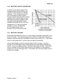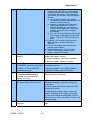
1
OPERATION AND SERVICE MANUAL
SPC LITE
Universal Portable Charger
Dual-Position
BTC-70819
NSN 6130-01-555-7817
USA Tel: (631) 499-5155 · Fax: (631) 499-5504
email address: [email protected]
www.bren-tronics.com
850036-1 REV E
WARNING
HIGH VOLTAGES ARE PRESENT IN THE
OPERATION OF THIS EQUIPMENT
Avoid contact with AC supply voltage connections during installation, operation
or maintenance of the battery charger.
CAUTION
ACID CONTAMINATES NICKEL-CADMIUM, LITHIUM-ION,
LITHIUM-POLYMER and NICKEL-METAL HYDRIDE BATTERIES
Every effort must be made to keep Nickel-Cadmium, Lithium-Ion, Lithium Polymer
and Nickel-Metal Hydride batteries as far away as possible from Lead-Acid
batteries because Lead-Acid batteries contain sulfuric acid. Do Not use the same
tools and materials, such as screwdrivers, wrenches, syringes, hydrometers, and
gloves for both types of batteries. Any trace of acid or acid fumes will
permanently damage Nickel-Cadmium, Lithium-Ion, Lithium Polymer and NickelMetal Hydride batteries on contact.
WARNING
NO SMOKING IS PERMITTED NEAR THE CHARGING STATION
Batteries can produce explosive gases during charging or discharge cycles.
Never smoke or allow open flames near the charging station.
Table of Contents
CHAPTER 1 – INTRODUCTION
Para
Scope......................................................... 1-1
Technical Specifications…………………... 1-2
Declaration of Conformity .......................... 1-3
Accessories…………………………………. 1-4
Charge Cycle Description…………………. 1-5
Updating Charger Software……………… 1-6
CHAPTER 2 – OPERATING PROCEDURES
Panel Controls and Indicators……………. 2-1
Preliminary Setup Procedures…………… 2-2
Charging Batteries………………………… 2-3
Battery Revitalization and De-Storage….. 2-4
Blackout…………………………………….. 2-5
Battery Charger Labels…………….
2-6
Solid Red Fault LED Troubleshooting…… 2-7
Flashing Red Fault LED Troubleshooting.. 2-8
850036-1 REV E
Para Pg
Pg
1-1
1-2
1-3
1-4
1-7
1-8
Operation in Extreme Environmental
Conditions............................................
Preparation for Movement.....................
Battery State-of-Charge Displays..........
Battery Capacity Retention....................
Battery Storage.....................................
2-1
2-4
2-5
2-6
2-7
2-8
2-9
2-9
CHAPTER 3 – MAINTENANCE INSTRUCTIONS
Introduction............................................. 3-1 3-1
Cleaning................................................. 3-2 3-1
Inspection............................................... 3-3 3-1
Basic Functional Test............................. 3-4 3-2
Simplified Operator
Troubleshooting Procedures................ 3-5 3-3
Warranty / Repair Information................ 3-6 3-5
Upgrade / Update Information................ 3-7 3-5
2-9
2-10
2-11
2-12
2-13
2-10
2-11
2-11
2-12
2-12
INTRODUCTION
CHAPTER 1
INTRODUCTION
1-1.
SCOPE
The Soldier Portable Charger Lite (P/N BTC-70819) is a state-of-the-art, high
performance lightweight portable battery charger designed for field deployment or shop
usage. It provides fast reactivation of various rechargeable batteries. It is capable of
simultaneously charging two batteries completely unattended.
The Soldier Portable Charger Lite (SPC Lite) is simple to use by design. Without any
user intervention, the SPC Lite typically charges two batteries. The charge time for a
fully discharged BB-2590/U or BB-390B/U is less than 3.5 hours. The Charge times are
substantially less for partially discharged batteries. The charger automatically identifies
the specific battery type and provides the appropriate charge profile. Based on the
current operating environment, the SPC Lite automatically customizes the charge profile
to provide the quickest charge in a safe manner. The charge status for the two batteries
is conveyed to the user via three easy-to-understand panel mounted LED indicators
(amber – CHARGE, green – READY and red – FAULT).
The SPC Lite is universal by design. It can readily use either AC or DC input power –
whichever is most convenient for the user. The universal AC input fully allows 90-264
VAC and 47-440 Hz operation without any adjustment or user intervention. Additionally,
the DC input power permits a range of 22-33 VDC, standard on most military vehicles.
The Charger is available with an additional 12 VDC input. This allows the Charger to be
powered from an 11-18 VDC such as a standard 12 VDC automotive system. When
operated with either DC power source, an Under-voltage Lockout Circuit prevents the
Charger from excessively discharging the vehicle battery so there is always enough
power to restart the vehicle.
The SPC Lite is adaptive by design. It is microprocessor controlled and is presently
programmed to automatically charge over 50 different battery types (and growing) as
listed in Table 1. With the appropriate battery adapter, however, it can be readily
reprogrammed via the RS232 software upgrade port in the field to charge a countless
number of additional battery types and chemistries including: Nickel Metal Hydride,
Nickel Cadmium, Lithium Ion, and Lithium Polymer.
The battery charger components are housed in a durable, solid polypropylene case. The
assembled unit is watertight when the cover is securely latched and the pressure
equalization valve is closed.
850036-1 REV E
1-1
INTRODUCTION
1-2.
TECHNICAL SPECIFICATIONS
Dimensions……………………….. 13.73 inches (348.8 mm) W x 10.28 inches (261 mm) D
x 7.65 inches (194.4 mm) H
Weight (less adapters and cables)…...13 lbs. (5.9 kg)
Power Requirements
AC Operation……………... Automatic Selection: 90 to 260 VAC, single-phase,
47 to 440 Hz
28V DC Operation………...22 to 33 VDC, 13A
12V DC Operation………...11 to 18 VDC, 20A (BTC-70819-3 Only)
Charging Output Voltage………... Automatically selected for each battery type
Duty Cycle………………………… Continuous
Protective Features………………. Resettable circuit breakers:
AC ( 3A)
28 VDC (13A)
12 VDC (20A)
Operating Temp. Range………… -4°F (-20°C) to +122°F (+50°C)
Storage Temp. Range…………… -40°F (-40°C) to +158°F (+70°C)
Case Material ……………………. Solid Polypropylene
Case Color………………………... Olive Drab #34088 per Fed-Std-595B
Shipment………………………….. No restrictions
850036-1 REV E
1-2
INTRODUCTION
1-3.
DECLARATION OF CONFORMITY
850036-1 REV E
1-3
INTRODUCTION
1-4.
ACCESSORIES
Table 1 shows the various batteries and appropriate adapter plates the SPC Lite supports at the
time this document was written.
Table 2 shows various power cables and accessories.
Table 1 – Supported Batteries and Adapters
ADAPTER
BTA-70360
BTA-70394
BTA-70395 (1)
ADAPTER NSN
6130-01-555-7818
5940-01-427-9247
5940-01-427-9183
BTA-70396
5940-01-427-9278
BTA-70443
5940-01-467-8813
BTA-70492A
5940-01-513-5662
BTA-70557
BTA-70574
BTA-70581
BTA-70581A
BTA-70582
5940-01-467-5852
5940-01-483-6772
--5940-01-544-3476
---
BTA-70582-1
---
BTA-70589
BTA-70589A
BTA-70598
BTA-70715
850036-1 REV E
6130-01-564-8116
---
--5940-01-573-9693
BATTERY
BB-4600
BB-503A/U
BB-326/U
BB-516A/U
BB-2847A/U
BB-2847/U
BB-2600/U
BB-2600A/U
BT-70477
BT-70492
BT-70492A
BB-557/U
ICOM SI
CSEL
CSEL
ALI 124
ALI 142/BA-682A
BA-682B
BA-684A
ALI 124
ALI 142/BA-682A
BA-682B
BA-684A
ALI 116
ALI 124
ALI 142/BA-682A
ALI 143/BA-687A
ALI 243
BA-684A
BA-685A
BA-682B
ALI 147
ALI 247
ALI 142/BA-682A
ALI 143/BA-687A
ALI 243
BA-684A
BA-685A
BA-682B
ALI 147
ALI 247
BT-70598
BT-70593
BT-70715
1-4
TYPE
NiCd
NiCd
NiMH
NiCd
Li Ion
Li Ion
Li Ion
Li Ion
NiMH
Li Ion
Li Ion
NiCd
NiCd
Li Ion
Li Ion
NiCd
Li Ion
Li Ion
Li Ion
NiCd
Li Ion
Li Ion
Li Ion
NiCd
NiCd
Li Ion
Li Ion
Li Ion
Li Ion
Li Ion
Li Ion
Li Ion
Li Ion
Li Ion
Li Ion
Li Ion
Li Ion
Li Ion
Li Ion
Li Ion
Li Ion
Li Ion
Li Ion
Li Ion
BATTERY NSN
6140-13-113-0171
6140-01-419-8193
6140-01-533-7674
6140-01-419-8191
6140-01-493-8092
6140-01-419-8194
6140-01-467-5853
6140-01-490-4311
6140-14-513-5369
6140-01-523-9840
6140-01-523-9840
6140-01-071-5070
--6140-01-534-3856
6140-01-534-3856
--6140-14-328-2258
6140-14-561-1542
6140-14-529-5971
--6140-14-328-2258
6140-14-561-1542
6140-14-529-5971
----6140-14-328-2258
6140-14-530-0061
6140-14-553-4062
6140-14-529-5971
6140-14-529-5973
6140-14-561-1542
----6140-14-328-2258
6140-14-530-0061
6140-14-553-4062
6140-14-529-5971
6140-14-529-5973
6140-14-561-1542
-----------
INTRODUCTION
BTA-70721
BTA-70732
BTA-70737
BTA-70740
BTA-70763
BTA-70774
6130-01-573-4962
------6130-01-555-7821
5940-01-573-9679
BTA-70807
BTA-70808
5940-01-493-6750
5940-01-493-6388
BTA-70810
BTA-70811
BTA-70812
5940-01-493-6751
5940-01-493-7622
5940-01-492-7238
BTA-70817
BTA-70834
--5940-01-501-3312
BTA-70899
---
BTA-70858
BTA-70406-3
BTA-70851 (1)
BTA-70852
BTA-70853
BTA-70872
BTA-70868
---------------
BTA-70706-1
BTA-70406
BTA-70661
BTA-70685
BTA-70838-7
-----------
BT-70721
BT-70732
BT-70737
BT-70740
BN-2250
Motorola –
NNTN7032A
NTN9816A
NTN9815A
BB-2800/U
BB-2588/U
BB-388/U
THALES – MBITR
AA CELLS
BB-2557/U
BB-557/U
D CELLS
BB-2590/U
BT-70791A
BT-70791E
BB-390B/U
BB-590/U
BT-70876
SAFT – SAI-2590
BB-2590/U
BB-390B/U
BT-70791A
BT-70791E
BT-70899A
BT-70876
Saft – SAI-2590
Ultralife – UBI-2590
DRT 4453/4411
BA-386
Racal 931
PTR-349
Loral – RT1606
BB-NM10
LI-145
LI-80
BB-2598
BB-586
BT-70661
ALKABAT
BT-70838 IdZ
BT-70838-2/3 IdZ
Li Ion
Li Ion
Li Ion
Li Ion
NiCd
Li Ion
NiCd
NiCd
Li Ion
Li Ion
NiMH
Li Ion
NiMH
Li Ion
NiCd
NiMH
Li Ion
Li Ion
Li Ion
NiMH
NiCd
Li Ion
Li Ion
Li Ion
NiMH
Li Ion
Li Ion
Li Ion
Li Ion
Li Ion
Li Ion
Li Ion
NiCd
NiCd
NiCd
NiCd
NiCd
Li Ion
Li Ion
Li Ion
NiCd
Li Ion
NiCd
Li Ion
Li Ion
--------6140-13-116-5482
--------6140-01-490-5372
6140-01-493-7623
6140-01-490-4313
----6140-01-490-5387
6140-01-071-5070
--6140-01-490-4316
----6140-01-490-4317
6140-01-063-3918
----6140-01-490-4316
6140-01-490-4317
------------------------------6140-01-084-1460
---------
NOTES:
1) The BB-516A,BB-326, and RACAL 931 can only charge with AC power on the BTC-70819.
There is no limitation on the BTC-70819-3
2) The Adapter BTA-70480/3 is not compatible with this charger.
3) This list was complete at the date of publication. Additional adapters may be available, but
may require updated software.
850036-1 REV E
1-5
INTRODUCTION
Table 2 – Power Cables and Accessories
DESCRIPTION
AC Power Cord US
AC Power Cord EU
AC Power Cord UK
DC Power Cable w/rings
DC Power Cable w/allig. clips
Gabriel DC Power Cable
DC Hummer Cable
DC Splitter Cable
BB-390/2590 Self Discharger
BTI P/N
591609
590233-3
590233-4
BTA-70844-24
BTA-70844-24-AL
BTA-70819-24
BTA-70835
BTA-70816
BTF-70791
GENERAL P/N
------------------------------J-6362A/U
CX-13560/G
SDD2
NSN
------------------------------5940-01-501-6714
5995-01-505-7883
6130-01-490-4310
Figure 1-4.1: BTA-70844-24
Figure 1-4.2: BTA-70835
Figure 1-4.3: BTA-70816(for use with
BTA-70835)
Figure 1-4.4: BTF-70791
850036-1 REV E
1-6
INTRODUCTION
1-5.
CHARGE CYCLE DESCRIPTION
Each of type the battery that are capable of being charged by the Charger is connected
to the charger via their respective battery adapter (plate or cable). Each adapter can
charge two batteries simultaneously. The appropriate battery adapter is installed on the
control panel and serves as the electrical interface between the batteries being charged
and the charger circuits. The battery charger control circuits constantly monitor the
following battery conditions during the charge cycle, as appropriate, to ensure that the
battery is properly being charged:
a. Temperature (T)
b. Voltage (V)
c.
Current (I)
d. Time (t)
e. Voltage change (ΔV)
f.
Temperature rate of change (ΔT/Δt)
The charger operation during a typical charge sequence is automatic and the battery
charge status is displayed to the user by the panel LED indicators as follows:
a. Detection - The charger tries to detect a battery in an adapter. The CHARGE
LED (amber) blinks slowly during this process.
b. Pre-charge – The charger brings the battery voltage up to a safe level before the
rapid charge process begins. This step may take several minutes for a very
discharged battery. The CHARGE LED (amber) blinks rapidly during this process.
c. Fast Charge – A timed fast charge cycle brings the battery to approximately 90%
of full charge capacity. The CHARGE LED (amber) is lit solid during this process.
d. Ready – The fast charge cycle is complete. The Battery may be removed and
used at this time. The READY LED (green) is lit steadily at this time.
e. Trickle / Top-off – When fast charge is complete, the charger will top off of the
battery to 100%. For Lithium Ion and Lithium Polymer batteries the top-off cycle
will stop after the battery is 100% charged. For all other types, the Trickle / Top-off
cycle is repeated indefinitely to keep the battery at 100% charge. Leaving the
battery on the charger will not harm the battery. The battery may be removed and
used at this time. The READY LED (green) blinks during this process.
NOTE
The Battery may be removed and used at anytime during the charge cycle without
damage to the charger or battery. If present, the state-of-charge indicator (SOC) will
display the battery condition.
NOTE
After removing a battery from the charger, wait for the corresponding battery status
LED’s to turn off before installing a new battery.
850036-1 REV E
1-7
INTRODUCTION
1-6.
UPDATING CHARGER SOFTWARE
The software in the charger is field upgradeable. By loading new software into the
charger, it is possible to alter its operation and add or change the charging profiles for
the batteries. Loading new software into the charger is accomplished via the use of a
standard RS232 interface of a personal computer (PC) running Windows 95™ or higher.
Utilizing special software running on the PC in conjunction with the boot program
resident within the charger, a two-way communication link is established and the revised
operational parameters and battery charge profiles can be loaded into the charger.
Specific instructions for upgrading the Charger software are provided with the software
upgrades.
850036-1 REV E
1-8
OPERATION
SECTION 2
OPERATING PROCEDURES
2-1. PANEL CONTROLS AND INDICATORS
Battery charger panel components are described below and shown in Figure 2-1.1 and
2-1.2
FIGURE 2-1.1
FIGURE 2-1.2
850036-1 REV E
2-1
OPERATION
Item
Function
1. On/Off Switch...................................... Turns battery charger on or off.
2. AC Circuit Breaker.............................. Turns power to the charger off in an overload
condition. Remove the overload condition and
push to reset.
3. Power On Indicator LED (Green)……. The Power On Indicator LED lights when the
charger has sufficient power from either AC or
DC.
4. Low Vehicle Power LED (Red)............ The Low Vehicle power indicator lights when
external DC power is too low to charge
batteries. The charger will stop charging
batteries until sufficient power is available from
the DC course.
5. Temp Fault LED (Amber).................... The Temperature Fault indicator lights when
charger temperature is too high (50°C) or too
low (-20°C). The charger will stop charging
batteries.
6. Blackout Switch……………………….. Enables / Disables Blackout Mode. Pressing it
once turns off all panel LEDs. Pressing it again
turns on all panel LEDs. Holding down the
button during turn-on keeps the LED’s off during
the Lamp Test.
7. DC Circuit Breakers............................ Turns power to the charger off in an overload
condition. Remove the overload condition and
push to reset.
8. Charge LED (Amber).......................... The Amber LED lights steady while the
associated battery is being fast-charged. A
slow blinking indication means the charger is
trying to find a battery at the select position. A
fast blinking indication means the charger is
preconditioning the battery before charging it.
9. Ready LED (Green)............................ The Green LED indicates the associated battery
is fully charged and ready to be removed for
use. Steady light means the battery has
completed fast charge. A blinking indication
means the battery is being topped off.
850036-1 REV E
2-2
OPERATION
10. Fault LED (Red)................................ If the Red LED lights steadily, the associated
battery, or adapter plate is defective or will not
accept charge. A blinking indication means the
battery’s temperature sensor or communication
connection is not making contact with the
adapter.
11. AC Input Connector........................... Input connection for AC cable assembly.
12. DC Input Connector.......................... Input connection for DC cable assembly.
13. Adapter Port………………………….. Provides interface connection for battery
adapters.
14. Recondition Switch………………….. Activates NiCd revitalization or Li-Ion destorage.
15. Recondition LED (Amber)…………... Lights amber during revitalization / de-storage
process.
16. RS-232 Port Cover………………...... Remove this cover to upgrade the charger’s software.
Otherwise leave the cover in place.
17. Pressure Equalization Valve………...This valve must be loosen before the cover is opened
and latches unfastened.
850036-1 REV E
2-3
OPERATION
2-2.
PRELIMINARY SETUP PROCEDURES
Step 1. Place the unit on the work surface. Loosen the Pressure Equalization Valve
(Fig 2.1-2 #17) by unscrewing the knob two full turns in a counterclockwise
direction. Unfasten latches and open cover.
Step 2. Set the On/Off Switch (Fig 2.1-1 #1) to OFF position.
Step 3. The cover may be removed by removing both hinge pins with pliers.
Step 4. For AC operation: Connect the AC power cord from AC Input Connector (Fig
2.1-1 #11) to an AC power source and set the On/Off Switch (Fig 2.1-1 #1) to
ON position. Observe that the Power On Indicator LED (Fig 2.1-1 #3) lights,
the fan operates, and all the indicator LEDs blink in order (amber, then green,
then red) briefly when power is first applied.
Step 5. For DC operation: Connect the DC cable from the DC Input Connector (Fig
2.1-1 #12) to a DC power source such as the NATO slave receptacle found in
most military vehicles. Set the On/Off Switch (Fig 2.1-1 #1) to the ON position.
Observe that the Power On Indicator LED (Fig 2.1-1 #3) lights, the fan
operates, and all the status indicator LEDs (Fig 2.1-1 #8, #9, and #10) blink in
order (amber, green, then red) briefly when power is first applied.
Note: If both Multiple Power Sources are connected:
•
For the BTC-70819-3 if AC and DC are connected the charger will use
AC power. If 12 and 28 VDC power are connected the charger will use
28VDC.
•
For the BTC-70819 if AC and DC are connected the charger will use DC
power.
Step 6. Observe that only the Power On Indicator LED (Fig 2.1-1 #3) is lit.
Step 7. Install the appropriate battery adapter into the Adapter Port (Fig 2.1-1 #13) for
battery type to be charged. Install the adapter by first placing the back of the
adapter into the rear retainer. Note the alignment of the pins. The connector can
only be plug in one way, do not force it. Be sure that battery adapter is fully
seated on the panel. For Cable adapters, line up the pins to the Adapter Port
(Fig 2.1-1 #13). 18 Pin Connectors will plug in toward the right side on the
charger, do not force the connector.
Step 8. Observe, after a short delay, that the two amber Charge LEDs (Fig 2.1-1 #8)
will blink for several seconds. This shows battery charger circuits are initialized
to the selected battery adapter and are ready to accept a battery (or batteries)
for charging. If all of the status indicator LEDs (Fig 2.1-1 #8, #9, and #10) for a
channel light at the same time, the adapter could not be recognized or the
adapter is damaged, insure it is seated correctly. If running on DC, verify that
the battery is supported by DC charging (ex: the BB516 is not). Verify that the
charger software revision supports the adapter and battery.
850036-1 REV E
2-4
OPERATION
2-3.
CHARGING BATTERIES
Step 1. With the appropriate battery adapter installed, insert the first battery to be
charged into the channel “A“ battery location. Insure the battery is fully seated
in the adapter. Observe that the amber Charge LED (Fig 2.1-1 #8) for the
corresponding location is lit or blinking rapidly. The Charge LED (Fig 2.1-1 #8)
for the “B” battery location will continue to blink if the channel “B” battery location
is left empty. If the red Fault LED (Fig 2.1-1 #10) is lit, the battery or adapter
may be defective, check by removing the battery and the adapter. Then reinstall
the adapter and battery. If the Fault LED (Fig 2.1-1 #10) still lights, go to the
Troubleshooting section (section 2.7, 2.8, and 3-5) of this Guide.
Step 2. Install the next battery into the Channel B battery location.
Step 3. After fast charging is complete, the amber Charge LED (Fig 2.1-1 #8) will turn
off and the green Ready LED (Fig 2.1-1 #9) will be lit. The charger will then topoff the batteries that have successfully completed fast charge. The battery is
slow-charged to full capacity, as indicated by the blinking green Ready LED (Fig
2.1-1 #9). For Lithium-ion batteries, the cycle will stop after the battery is 100%
charged. For other types the cycle is repeated indefinitely to keep the battery at
100% charge. As long as the green Ready LED (Fig 2.1-1 #9) is lit (blinking or
solid) the battery may be removed and returned to service and another battery
may be installed for charging.
NOTE
The BB-390A/U and the BB-390B/U batteries include two independent
12-volt sections. A relay "clicking" may be heard from the battery
adapter when battery sections are switched. Other types of adapters
may also contain relays and click intermittently during normal operation.
NOTE
Battery charger power may be left ON while batteries and/or adapters are
removed or replaced. Batteries may be left on the charger for long
periods of time without damaging the batteries or the charger. This is true
whether if the charger is on or off.
850036-1 REV E
2-5
OPERATION
2-4.
BATTERY REVITALIZATION AND DE-STORAGE
The procedures outlined below describe the means of invoking the Revitalization
and De-storage functions of the charger as well as the sequence of operations the
charger will execute to perform the commanded tasks.
NiCd and Ni-Mh Batteries are revitalized. Li-Ion batteries are de-stored.
The charger will decide what to do based on the batteries’ chemistry.
a. NiCad and Ni-Mh Revitalization
Due to the increased power dissipation from discharging the batteries, this function
will not operate above 45º C. The following procedure is used to invoke the
Revitalization process:
1. Power up the charger.
2. Plug in adapter.
3. Once the adapter is recognized (the two amber Charge LED (Fig 2.1-1 #8)
blink) press the Recondition Switch (Fig 2.1-1 #14) for the A or B channel;
the amber Recondition LED (Fig 2.1-1 #15) will light for the corresponding
channel.
4. Plug the battery into the activated channel.
5. Revitalization will commence upon recognition of the battery.
Autonomously, the charger will perform the following revitalization sequence:
1. Check environment temperature, if the temperature is above 45º C it will
not proceed.
2. Discharge the battery without a capacity measurement.
3. Fully charge the battery.
4. Discharge the battery and calculate the capacity.
5. Fully charge the battery.
6. If the capacity in step 4 is greater than or equal to 80% of the battery
specification, the green Ready LED (Fig 2.1-1 #9) will light, and the
Recondition LED (Fig 2.1-1 #15) will remain lit and the process is complete.
7. If the capacity in step 4 is less than 80%, steps 4 and 5 will repeat a
second time. If after the second cycle the capacity is less than 80% of the
battery specification, the red Fault LED (Fig 2.1-1 #10) will light. The
Recondition LED (Fig 2.1-1 #15) remains lit and the process is complete.
b. Li-Ion De-storage
Due to the increased power dissipation from discharging the batteries, this function
will not operate above 45º C. The following procedure is used to invoke the destorage process:
1. Power up the charger.
2. Plug in adapter.
3. Once the adapter is recognized (the two amber Charge LED (Fig 2.1-1 #8)
blink) press the Recondition Switch (Fig 2.1-1 #14) for the A or B channel;
850036-1 REV E
2-6
OPERATION
the amber Recondition LED (Fig 2.1-1 #15) will light for the corresponding
channel.
4. Plug the battery into the activated channel.
5. De-storage will commence upon recognition of the battery. Autonomously,
the Charger will perform the following de-storage sequence:
a. Check environmental temperature, if the temperature is above 45º C it
will not proceed.
b. Fully discharge the battery.
c. Fully charge the battery while measuring its capacity.
d. Discharge the battery to 45% of it measured capacity.
e. The green Ready LED (Fig 2.1-1 #9) will light, the Recondition LED
(Fig 2.1-1 #15) remains lit and the process is complete.
2-5.
BLACKOUT
Pressing the Blackout Switch (Fig 2.1-1 #6) will turn off all the LEDs. Pressing the
switch again will turn the LEDs back on. The charger will remember the correct
state for all batteries. The blackout mode is disabled each time the charger is turned
on.
Holding the Blackout Switch (Fig 2.1-1 #6) down while turning the charger power
switch on will suppress the startup LED Test.
850036-1 REV E
2-7
OPERATION
2-6.
BATTERY CHARGER LABELS
Shown below are the instructions contained on the "SHORT FORM - OPERATING
PROCEDURE" label, attached inside the charger cover.
LED INDICATIONS FOR EACH BATTERY
S = STEADY, F = FLASHING
S=Steady
F= Flashing
AMBER GREEN RED
LIGHT INDICATIONS FOR EACH BATTERY
RECON DEFINITION
REMARKS
F
F
LIGHTS SCROLL MOMENTARILY
ADAPTERS MUST BE
INSTALLED
AWAITING BATTERY TO
CHARGE (SLOW BLINKING)
F
F
CHARGER START UP
NO ADAPTER PRESENT
F
NO BATTERY PRESENT
F
CHARGE PREQUALIFICATION
PRE-CHARGE CHECK (RAPID
BLINKING)
S
FAST CHARGE IN PROCESS
TWO BATTERIES CAN CHARGE
SIMULTANEOUSLY
F
TRICKLE CHARGE IN PROCESS
BATTERY IS READY TO USE;
REMOVE WHEN READY
S
CHARGE IS COMPLETE
S
FAULTY BATTERY: DO NOT USE
F
CONTACT PINS ARE DIRTY OR
DAMAGED
CLEAN BATTERY CONTACTS;
CHECK ADAPTER PINS
RECONDITION/DESTORE CYCLE
IN PROCESS
RECONDITION (Ni); DESTORE
(Li)
RECONDITION/DESTORE FAILED
CONSULT STANDARD
OPERATING PROCEDURE
EXCESSIVE TEMPERATURE FOR
RECONDITIONING
RELOCATE TO COOLER
ENVIRONMENT
INCOMPATIBLE BATTERY OR
ADAPTER.
INSUFFICIENT DC VOLTAGE TO
CHARGE THIS BATTERY TYPE
UNSUPPORTED OR SOFTWARE
UPDATE REQUIRED
S
S
S
BATTERY IS READY TO USE;
REMOVE WHEN READY
CONSULT STANDARD
OPERATING PROCEDURE
S
F
S
S
S
S
S
S
850036-1 REV E
2-8
USE AN AC POWERSOURCE
OPERATION
2-7.
SOLID RED FAULT LED TROUBLESHOOTING
1. Remove the battery and inspect all the contacts, clean if necessary. Note
the battery location.
2. Reinstall at the same location for another charge cycle.
3. If the Fault LED (Fig 2.1-1 #10) is lit again at the same location remove
battery and do the following:
a. If the battery is NiCad or Ni-Mh and was in storage, try to revitalize
the battery (see section 2.4).
b. Check battery: If the battery is older than 3 yrs, it may be ready for
disposal.
c. Check the warranty instructions on the battery. If the warranty is
expired or no instructions were given on the battery, dispose of the
battery.
d. Note success/failure of the future battery charges at this battery
location. If the Fault LED (Fig 2.1-1 #10) is lit again, the adapter may
need to be changed.
2-8.
FLASHING RED FAULT LED TROUBLESHOOTING
1. This condition is telling you that some of the battery contacts are not
connecting to the charger.
a. For BB-390 and other batteries with thermistors, the thermal
contacts may not be making proper contact with the adapter.
b. For Falcon, CSEL, MBITR, and other batteries the communication
pin(s) may not be making proper contact with the adapter.
c. To minimize this issue; before you first start using the charger,
ensure the battery contacts are clean and the adapter contact pins are
in place and retain their spring action: Check by pushing down the pins
and releasing.
2. You can still charge batteries with thermal / communication pins missing or
damaged, it will take longer, and may not fully charge in one cycle.
3. If the flashing "red" condition continues, note the adapter battery location
and battery affected.
a. Remove the battery and clean the thermal contacts.
b. Check adapters again. If problem continues at this location, the
adapter may need to be changed.
850036-1 REV E
2-9
OPERATION
2-9.
OPERATION IN EXTREME ENVIRONMENTAL CONDITIONS
Observe these precautions when the charger is operated in areas where severe
climatic conditions may exist:
a. Operation in Arctic Climates. The battery charger is designed to function
in temperature extremes as low as -4°F (-20°C). However, when operating
in arctic climates, the following precautions should be observed:
(1) Handle the equipment carefully. The plastic components may become
more brittle.
(2) Keep the equipment clean and dry.
(3) Prevent ice from forming on the charger and the batteries. Ice
formations may prevent proper electrical connections. Melting ice may
allow water to enter the charger.
When not in use, be sure the cover is fully latched and the Pressure
Equalization Valve (Fig 2.1-2 #17) is fully closed (tighten by turning the
knob in clockwise direction).
b. Operation in Desert Climates. The charger is designed to operate in
temperature extremes as high as 122°F (50°C) and the dryness associated
with a desert environment. However, the sand and dust accumulation on
and in the charger may cause poor electrical connections and reduce the
cooling effectiveness of the charger. Follow proper cleaning and
maintenance guidelines (Section 3-2) to assure proper operation. When
not in use, be sure the cover is fully latched and the Pressure Equalization
Valve (Fig 2.1-2 #17) is fully closed (tighten by turning the knob in clockwise
direction).
c. Operation in Salt Spray. Keep the equipment clean and dry at all times
and immediately wipe salt spray from all the exposed surfaces on the
charger and cables and connectors. When not in use, be sure the cover is
fully latched and the Pressure Equalization Valve (Fig 2.1-2 #17) is fully
closed (tighten by turning the knob in clockwise direction).
d. Operation in Rain. Keep the equipment dry at all times. Water
penetration in the charger, cables and the connectors will cause equipment
failure. When not in use, be sure the cover is fully latched and the
Pressure Equalization Valve (Fig 2.1-2 #17) is fully closed (tighten by
turning the knob in clockwise direction).
850036-1 REV E
2-10
OPERATION
NOTE
Battery charge acceptance varies with ambient temperature
conditions. At temperatures lower than 32°F (0°C) or higher than
104°F (40°C) it may be necessary to initiate two complete charging
cycles to achieve full charge on the battery.
2-10. PREPARATION FOR MOVEMENT
a. Set the On/Off Switch (Fig 2.1-1 #1) to OFF position.
b. Remove any installed batteries.
c. Disconnect the AC power cable.
d. Disconnect the DC power cable.
e. Unplug cable type adapters. (Plate type adapter may be left installed.)
f. Replace the charger cover if it was removed.
g. Close the charger cover and secure latches.
h. Close the Pressure Equalization Valve (Fig 2.1-2 #17) by turning
clockwise until tight.
2-11. BATTERY STATE-OF-CHARGE DISPLAYS
Batteries equipped with state-of-charge (SOC) displays indicate battery charge
status on a five-segment LCD bar graph readout. The number of LCD segments
activated corresponds to the battery’s state-of-charge as follows:
Segments
0
1
2
3
4
5
State-of-Charge
0% (fully discharged)
1 to 20%
21 to 40%
41 to 60%
61 to 80%
81 to 100% (fully charged)
NOTE
The BB-390A/U, BB-390B/U, BB-2590/U, BB-2557/U and other
batteries have two SOC indicators. Each SOC indicator provides
state-of-charge indication for each of the two 12V sections. Both
SOCs must display 100% for the battery to be fully charged.
850036-1 REV E
2-11
OPERATION
2-12. BATTERY CAPACITY RETENTION
As shown in the adjoining graph, fully
charged batteries that are stored, lose
a portion of their charge due to battery
chemistry. This is normal and should
not be interpreted as battery failure.
Storage at higher temperatures increases
capacity losses, while storage at lower
temperature decreases capacity losses.
The graph shows that Nickel based
batteries like the BB-390 lose over 30%
charge/month (1% /day) on the shelf
waiting to be used. The BB-2590
(a Li-Ion based battery) loses
less than 10% a month on the shelf.
2-13. BATTERY STORAGE
Nickel based batteries may require 1 or more charge / discharge cycles after a long
period of storage. They may not charge fully on the first charge cycle. Repeat the
charge if necessary using the Revitalizations feature (see section 2.4). If the battery
does not fully charge after 3 cycles it may no longer be serviceable.
Lithium based batteries must be charged yearly if held in storage. Long term
storage of fully discharged Lithium based batteries can permanently damage the
battery. They do not require charge / discharge cycling after storage. If the battery
does not charge (No SOC Bars), place it back on the charger for one additional
charge cycle. Do not discharge it first. If the battery does not fully charge it may no
longer be serviceable.
850036-1 REV E
2-12
MAINTENANCE
SECTION 3
OPERATOR MAINTENANCE INSTRUCTIONS
3-1.
INTRODUCTION
Periodic maintenance, inspection and cleaning will help insure the Charger is kept at
full readiness.
3-2.
CLEANING
1. Brush loose dirt and dust from the charger. Low-pressure air may be used
to remove heavy dust from the case, connectors and power switches. Avoid
blowing dust into the unit. Low-pressure air may be blown into the left and
right air vents at the edge of the control panel to help remove internal dust.
2. Wipe surfaces with a damp (not wet) rag. Non-solvent cleaners may be
used (Windex™, Fantastik™, and Formula 409™). Do not spray or drip
water or cleaners onto the panel or into the connectors.
3. The flush mounted adapter connectors may be cleaned with electronic
grade spray cleaner. Allow the cleaner to dry before installing the adapters
and/or applying power to the charger.
4. The connections on the adapters may be cleaned with electronic grade
spray cleaner or isopropyl alcohol. Insure the adapters are dry before using
them.
3-3.
INSPECTION
1. Inspect case for cracks and other damage.
2. Insure the lid gasket is in place.
3. Insure the Hinge Pins are fully inserted (some models of charger also
include cover stays).
4. Insure the lid closes and can be properly latched.
5. Insure all Screws are in place and are not loose.
6. Inspect the panel and connectors for damage.
7. Inspect all adapters for excessive wear and damage.
a. Inspect charger connector for bent or corroded pins.
b. Inspect battery connector pins for damage or corrosion.
c. Insure all spring pins are not bent and move freely.
d. Note that spring pins can be removed and replaced.
8. Inspect power cords for damage.
9. Insure power switches move freely.
10. Insure the Pressure Equalization Valve (Fig 2.1-2 #17) can be tightened.
850036-1 REV E
3-1
MAINTENANCE
3-4.
BASIC FUNTIONAL TEST
1. Set the On/Off Switch (Fig 2.1-1 #1) to OFF position, and remove any adapter
installed.
2. Connect the charger to AC power.
3. Set the On/Off Switch (Fig 2.1-1 #1) to ON position.
4. The front panel LED’s should light in sequence. Amber, then Green, then Red.
Insure all LED’s light.
5. Insure the Power On Indicator LED (Fig 2.1-1 #3) is lit and that all other
indicator LEDs are off.
6. Place an adapter into the Adapter Port (Fig 2.1-1 #13).
7. Verify that the two Charge LEDs (Fig 2.1-1 #8) start to blink.
8. Press each of the Recondition Switch (Fig 2.1-1 #14) several times. Verify the
Recondition LED (Fig 2.1-1 #15) alternates on then off with each press.
9. Place a battery on Channel A. Insure that the Charge LEDs (Fig 2.1-1 #8) blinks
rapidly then turns on solid.
10. Repeat Step 9 for Channel B.
11. Set the On/Off Switch (Fig 2.1-1 #1) to OFF position and disconnect AC Power.
12. Connect the charger to 28 Volts DC power.
13. Set the On/Off Switch (Fig 2.1-1 #1) to ON position.
14. The front panel LED’s light in sequence. Amber, then Green, then Red. Insure
all LED’s light.
15. Press the Blackout Switch (Fig 2.1-1 #6). Verify that all panel LEDs turn off.
16. Press the Blackout Switch (Fig 2.1-1 #6) again. Verify all panel LEDs resume
normal operation.
17. For the BTC-70819-3 Only
a. Set the On/Off Switch (Fig 2.1-1 #1) to OFF position and disconnect the 28
Volts DC Power.
b. Connect the charger to 12 Volts DC power.
c. Set the On/Off Switch (Fig 2.1-1 #1) to ON position.
d. The front panel LED’s light in sequence. Amber, then Green, then Red.
Insure all LED’s light.
18. End of test.
850036-1 REV E
3-2
MAINTENANCE
3-5.
SIMPLIFIED OPERATOR TROUBLESHOOTING PROCEDURES
Item MALFUNCTION
1
POSSIBLE CORRECTIVE ACTION
POWER ON LED is not lit during AC
operation.
2
POWER ON LED is not lit during
DC operation.
3
All LED’s light and stay lit after
the charger is turned on.
4
The LED’s do not blink in
sequence at start up.
5
TEMP FAULT LED is lit.
6
7
8
1) Inspect Power Cord and DC Switch.
2) Reset DC Circuit Breaker. Note: The Circuit
breaker is tripped if the white band is visible.
1) The unit has lost its program.
a. Re-program the unit.
b. The unit requires repair. Call or e-mail
Bren-Tronics. Info on warranty tag.
1) Verify the Temp Fault and Veh Power
indicators are not lit.
2) The unit requires repair. Call or e-mail BrenTronics. Info on warranty tag.
1) The Charger is too hot or too cold. Move the
charger to a more suitable environment.
2) The air vents at the left and right side of the
charger are blocked.
3) Operating the chargers edge to edge can
cause overheating of the charger on the right.
4) One of the internal fans has failed. The unit
requires repair. Call or e-mail Bren-Tronics. Info
on warranty tag.
LOW VEH PWR LED is lit.
1) If the unit is running from DC power verify the
voltage is correct.
2) If the unit is running from AC power the unit
requires repair.
1) Poor connection between Adapter and
Charger. Inspect, clean and reseat Adapter.
2) Defective Adapter, use a different Adapter.
3) The charger does not support the Adapter.
Update the charger software See para 3-7.
All 3 LED’s (CHARGE, READY,
FAULT) are lit.
FAULT LED is lit.
850036-1 REV E
1) Inspect Power Cord and AC Switch.
2) Reset AC Circuit Breaker. Note: The Circuit
breaker is tripped if the white band is visible.
1) Check battery: older than 3 yrs? Maybe ready
for disposal. Discharge & recharge or Revitalize,
IF RED AGAIN?
2) Check warranty instructions on battery. If not
covered or no instructions, dispose of.
3) Note success/failure of future battery charges
at this Port. More "RED" lights? Change adapter.
3-3
MAINTENANCE
9
FAULT LED is blinking.
1) This condition is telling you the thermal
contacts on the BB-390 or communication
contacts on other batteries are not making
contact with the charger. To minimize this
issue before you first start using the charger:
Ensure….
a) Two Thermal contacts are in place in
each battery position on the BB-390, or all
contacts on other batteries.
b) Adapter contact pins are in place and
retain their spring action: Check by
pushing down the pins and releasing.
The pins should spring up. If not or are
missing, you may be able to replace
pins/adapter.
c) You can still charge Batteries with contact
pins missing or damaged, it will just take
longer. The FAULT LED will continue to
blink.
2) If flashing "red" condition after this check,
Mark location of condition and battery
affected.
3) You can pull batteries and clean thermal
contacts on the battery.
4) Check adapters again. Mark for future
review. If a problem continues at this
location, change the Adapter.
1) Possible poor connection, inspect and clean
battery and adapter contacts.
2) Defective adapter, use a different adapter.
3) Defective battery, replace the battery.
1) Poor connection, inspect and clean battery
and adapter contact.
2) Defective adapter, use a different adapter.
3) Defective battery, replace the battery.
10
Charger never tries to charge a
battery.
11
Port LED goes to Amber
(CHARGE), but never turns Red
(FAULT) or Green (READY),
instead it turns off.
12
Recondition LED will not turn on
when Recondition Switch is
pressed or turns off when the
battery is “Found”.
Recondition LED is blinking and
the Port’s Status LEDs are all off.
1) The Battery or Adapter does not support
Reconditioning or Destorage.
Fault LED stays lit after battery is
removed.
1) Battery is defective. Cycle power to clear
fault.
13
14
850036-1 REV E
3-4
1) The charger is too hot (over 45˚C) to
discharge the battery. Move the charger to a
cooler area.
2) The air vents at the left and right side of the
charger are blocked.
3) Operating the chargers edge to edge can
cause overheating of the charger on the right.
4) One of the internal fans has failed. The unit
requires repair. Call or e-mail Bren-Tronics. Info
on warranty tag.
MAINTENANCE
3-6.
WARRANTY / REPAIR INFORMATION
If the Charger or Adapters fail to function they must be returned to Bren-Tronics for repair.
The warranty label gives the expiration date on each unit. Contact Bren-Tronics for a
Return Material Authorization (RMA) number before returning any hardware to Bren-Tronics.
The part numbers, serial numbers and failure descriptions must be included for Bren-Tronics
to issue an RMA number. Chargers that have been damaged by abuse or that are no
longer under warranty may be returned for a repair quotation. There are no user
repairable parts in the charger. Opening the charger will void the warranty.
For return authorization call (631) 499-5155 or email [email protected]
3-7.
UPGRADE / UPDATE INFORMATION
The Charger Operation Software is field upgradeable. Updates usually add support
for additional battery adapters. They may also include enhanced battery charging
methods. The upgrade can be done with a PC running Windows 95 or newer in
about 15 minutes. All that is required is a computer serial cable and a screwdriver.
Information about new adapters and software can be found at:
http://www.bren-tronics.com
Call (631) 499-5155
or
Email [email protected]
850036-1 REV E
3-5