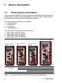
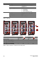
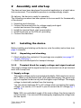
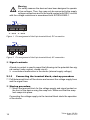
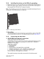
1
Hardware Installation Guide Tofino™ Argon 220 Security Appliance Release 04 04/2010 Tofino Argon 220 SA TX/TX Tofino Argon 220 SA MM/TX Tofino Argon 220 SA MM/MM Tofino Argon 220 SA TX/MM Technical Support [email protected] Copyright Information ©Byres Security Inc. While this information is presented in good faith and believed to be accurate, Byres Security Inc. disclaims the implied warranties of merchantability and fitness for a particular purpose and makes no express warranties except as may be stated in its written agreement with and for its customers. In no event is Byres Security Inc. liable to anyone for any indirect, special or consequential damages. The information and specifications in this document are subject to change without notice. Tofino™, Tofino™ Industrial Security Solution and Tofino™ Intrinsically Secure are trademarks of Byres Security Inc. Other brand or product names are trademarks of their respective owners. While every precaution has been taken in the preparation of this document, the publisher and the author assume no responsibility for errors or omissions, or for damages resulting from the use of information contained in this document or from the use of programs and source code that may accompany it. In no event shall the publisher and the author be liable for any loss of profit or any other commercial damage caused or alleged to have been caused directly or indirectly by this document. 039 741-001-04-0410 – 30.3.10 Content Safety instructions 4 Legend 7 1 Device description 8 1.1 General device description 8 1.2 Description of the device variants 11 2 Assembly and start-up 13 2.1 Installing the device 2.1.1 Unpacking and checking 2.1.2 Terminal block for supply voltage and signal contact 2.1.3 Connecting the terminal block, start-up procedure 2.1.4 Installing the device on the DIN rail, grounding 2.1.5 Connecting the data lines 2.1.6 Connection to the network 13 13 13 14 15 15 16 2.2 Display elements 16 2.3 Controls 18 2.4 Basic set-up 2.4.1 Default settings 2.4.2 USB interface 2.4.3 V.24 interface 19 19 19 21 2.5 Configuration 21 2.6 Network modes 22 2.7 Disassembly 23 3 Technical data 24 A Technical Support 31 Tofino Argon 220 SA Release 04 04/10 3 Safety instructions This documentation contains instructions which must be observed to ensure your own personal safety and to avoid damage to devices and machinery. Certified usage Please observe the following: The device may only be employed for the purposes described in the catalog and technical description, and only in conjunction with external devices and components recommended or approved by the manufacturer. The product can only be operated correctly and safely if it is transported, stored, installed and assembled properly and correctly. Furthermore, it must be operated and serviced carefully. Supply voltage For safety reasons the devices have been designed to operate at low voltages. Thus, they may only be connected to the supply voltage connections and to the signal contact with SELV circuits with the voltage restrictions in accordance with IEC/EN 60950-1. The supply voltage is electrically isolated from the housing. Use only undamaged parts. Relevant for North America: For use in Class 2 circuits. The device may only be connected to a supply voltage of class 2 that fulfills the requirements of the National Electrical Code, Table 11(b). If the voltage is being supplied redundantly (two different voltage sources), the combined supply voltages must fulfill the requirements of the National Electrical Code, Table 11(b). Relevant for North America: For use in Class 2 circuits. Only use copper wire/conductors of class 1, 60/75°C or 75°C. Shielding ground The shielding ground of the connectable twisted pairs lines is connected to the front panel as a conductor. Beware of possible short circuits when connecting a cable section with conductive shielding braiding. Housing Only technicians authorized by the manufacturer are permitted to open the housing. The lower panel of the device is grounded by means of the DIN rail and optionally by means of the separate ground screw. Make sure that the electrical installation meets local or nationally applicable safety regulations. 4 Tofino Argon 220 SA Release 04 04/10 Theventilation slots must not be covered so as to ensure free air circulation. The clearance to the ventilation slots of the housing must be at least 10 cm (3.94 in). Warning! Never insert sharp objects (small screwdrivers, wires, etc.) into the inside of the product. There is the risk of an electric shock. The device must be installed in the vertical position (see fig. 3). If installed in a living area or office environment, the device must be operated exclusively in switch cabinets with fire protection characteristics according to EN 60950-1. Environment The device may only be operated at the specified maximum ambient temperature (temperature of the surrounding air at a distance of up to 5 cm (1.97 in) to the device) and relative air humidity (non-condensing). Install the device in a location where the climatic threshold values specified in the technical data are adhered to. Only to be used in an environment with a pollution degree specified in the technical data. Qualification requirements for personnel Qualified personnel as understood in this manual and the warning signs, are persons who are familiar with the setup, assembly, startup, and operation of this product and are appropriately qualified for their job. This includes, for example, those persons who have been: X trained or directed or authorized to switch on and off, to ground and to label power circuits and devices or systems in accordance with current safety engineering standards; X trained or directed in the care and use of appropriate safety equipment in accordance with the current standards of safety engineering; X trained in providing first aid. General safety instructions Electricity is used to operate this equipment. Comply with every detail of the safety requirements specified in the operating instructions regarding the voltages to apply (see page 4). Non-observance of these safety instructions can therefore cause material damage and/or serious injuries. Only appropriately qualified personnel should work on this device or in its vicinity. These personnel must be thoroughly familiar with all the warnings and maintenance procedures in accordance with this operating manual. Tofino Argon 220 SA Release 04 04/10 5 The proper and safe operation of this device depends on proper handling during transport, proper storage and assembly, and conscientious operation and maintenance procedures. Never start operation with damaged components. Only use the devices in accordance with this manual. In particular, observe all warnings and safety-related information. Any work that may be required on the electrical installation may only be carried out by personnel trained for this purpose. Note: LED or LASER components in compliance with IEC 60825-1 (2001): CLASS 1 LASER PRODUCT CLASS 1 LED PRODUCT National and international safety regulations Make sure that the electrical installation meets local or nationally applicable safety regulations. Note on the CE marking The devices comply with the regulations contained in the following European directives: 2004/108/EG Directive of the European Parliament and the Council for standardizing the regulations of member states on electromagnetic compatibility. In accordance with the above-named EU directives, the EU conformity declaration will be at the disposal of the relevant authorities at the following address: Hirschmann Automation and Control GmbH Stuttgarter Str. 45-51 72654 Neckartenzlingen Germany Tel.: +49 1805 141538 The product can be used in living areas (living area, place of business, small business) and in industrial areas. X Interference immunity: EN 61000-6-2:2005 X Emitted interference: EN 55022:2006 Class A 6 Tofino Argon 220 SA Release 04 04/10 Warning This is a class A device. This device can cause interference in living areas, and in this case the operator may be required to take appropriate measures. The assembly guidelines provided in these instructions must be strictly adhered to in order to observe the EMC threshold values. FCC note: Appropriate testing has established that this device fulfills the requirements of a class A digital device in line with part 15 of the FCC regulations. These requirements are designed to provide sufficient protection against interference when the device is being used in a business environment. The device creates and uses high frequencies and can radiate same, and if it is not installed and used in accordance with this operating manual, it can cause radio transmission interference. The use of this device in a living area can also cause interference, and in this case the user is obliged to cover the costs of removing the interference. Recycling note After usage, this product must be disposed of properly as electronic waste, in accordance with the current disposal regulations of your county, state and country. Legend The symbols used in this manual have the following meanings: X Listing Work step Subheading Tofino Argon 220 SA Release 04 04/10 7 1 Device description 1.1 General device description The Industrial ETHERNET Security Appliance Tofino Argon 220 ensures the authentication, security and confidentiality of communication within production networks, but also beyond company boundaries. The devices have the following interfaces: X 1 untrusted port X 1 trusted port X 1 V.24 input X 1 USB interface You can choose from several device variants: X Tofino Argon 220 SA TX/TX X Tofino Argon 220 SA TX/MM X Tofino Argon 220 SA MM/TX X Tofino Argon 220 SA MM/MM Tofino Argon 220 SA TX/MM 1 Tofino Argon 220 SA TX/TX Tofino Argon 220 SA MM/TX Tofino Argon 220 SA MM/MM 2 3 4 5 6 7 8 9 1 2 Terminal block connection Power supply Signal contact LED display elements Table 1: 8 Pluggable 6-pin Connection Overview: interfaces, display elements and operating elements Tofino Argon 220 SA Release 04 04/10 3 4 Button Port 1 Untrusted Save/Load/Reset Either TX or MM, Twisted pair Standard depending on (TX ports) device variant Connection type Supports Fiber optic (MM ports) 5 USB interface 6 7 Device ID Port 2 Trusted 8 9 V.24 interface Grounding screw Table 1: ISO/IEC 8802-03 10BASE-T/ 100BASE-TX RJ45 X X X X Autonegotiation Autopolarity Autocrossing Full or half duplex mode Type of fiber Multimode Standard ISO/IEC 8802-03 100BASE-FX Connection DSC type Supports Full or half duplex mode USB storage device Either TX or MM, Twisted pair Standard depending on (TX ports) device variant Connection type Supports ISO/IEC 8802-03 10BASE-T/ 100BASE-TX RJ45 X X X X Autonegotiation Autopolarity Autocrossing Full or half duplex mode Fiber optic Type of fiber Multimode (MM ports) Standard ISO/IEC 8802-03 100BASE-FX Connection DSC type Supports Full or half duplex mode The V.24 interface is not active in this version of firmware. Overview: interfaces, display elements and operating elements You can use the devices everywhere that security-sensitive network equipment or zones require a connection out in a harsh environment. The Tofino Argon 220 devices are the link between the “secure” network and the “unsecured outside world”. In their function as a link, the devices protect the security-sensitive systems from undesired data traffic from the outside world. Tofino Argon 220 SA Release 04 04/10 9 Typical uses are: X X X X X X X X X Protecting individual production cells in a flat company network Protecting individual production cells in a routed company network Connecting a production cell with the office network via a public network Providing protected remote service access Segmenting control networks into security zones Creating encrypted 'tunnels' between remote sites and central facilities Securing connections to partner networks Protecting wireless networks Separating Safety Integrated Systems The devices support the following security functions: X Stateful Firewall (FW) X Virtual Private Network (VPN) X Denial of Service Traffic Limiter X Device Detection and Identification (Secure Asset Management) X Security Alarm and Event Logging All security functions are installed as separately purchased Loadable Security Modules (LSM). These can be added or removed at any time. Name Tofino Argon Firewall LSM Tofino Argon Secure Asset Management LSM Tofino Argon Modbus TCP Enforcer LSM Tofino Argon VPN Server LSM Tofino Argon VPN Client LSM Tofino Argon Event Logger LSM Tofino Argon VPN PC Client Lizence Order number LSM-FW-100 LSM-SAM-100 LSM-MBT-100 LSM-VPNS-100 LSM-VPNC-100 LSM-LOG-100 LSM-VPNL-100 The devices support the following network modes: X Passive Mode X Test Mode X Operational Mode The Tofino Argon 220 devices are designed for the special requirements of industrial automation. They meet the relevant industry standards, provide very high operational reliability, even under extreme conditions, and also long-term reliability and flexibility. The devices work without a fan. The voltage is supplied redundantly. Mount the devices by X simply snapping them onto a DIN rail 10 Tofino Argon 220 SA Release 04 04/10 Among others, the devices have the following important features: Management Redundant power supply Operating temperature Housing X Tofino Central Management Platform (CMP) Protocol X Syslog Safety extra-low voltage (SELV), redundant inputs disconnected. Relevant for North America: NEC Class 2 power source max. 5A. Operating voltage Rated voltage range DC 12 to 48 V DC Rated voltage range AC 24 V AC Surrounding air 0 °C to +60 °C Mounting 35 mm DIN rail (DIN EN 60175) Protection class IP 20 USB storage X Saving diagnostic files and log files to USB storage device X Loading configuration files from USB storage device device Certifications / decla- X German Lloyd X cUL 508 / CSA C22.2 No.142 rations Table 2: Important features 1.2 Description of the device variants You can choose from several device variants: X Tofino Argon 220 SA TX/TX X Tofino Argon 220 SA TX/MM X Tofino Argon 220 SA MM/TX X Tofino Argon 220 SA MM/MM The abbreviations in the device names denote the ports of the device. The first abbreviation stands for interface 1 (untrusted port), the second stands for interface 2 (trusted port). X For VPN deployment the “untrusted” interface of the Tofino Argon 220 Security Appliance must be used as the encrypted (i.e. external-facing) connection to the network. X For all other applications, using the untrusted port as the external-facing connection is optional, but highly recommended to simplify the rule configuration. The following table shows the meaning of the abbreviations in the device names. Tofino Argon 220 SA Release 04 04/10 11 Abbreviation Meaning TX Media type Standard Connection type Supports MM Media type Standard Connection type Type of fiber Supports Twisted pair ISO/IEC 8802-03 10BASE-T/ 100BASE-TX RJ45 X Autonegotiation X Autopolarity X Autocrossing X Full or half duplex mode Fiber optic cable ISO/IEC 8802-03 100BASE-FX DSC Multimode Full or half duplex mode Table 3: Naming Tofino Argon 220 SA TX/TX Tofino Argon 220 SA MM/TX Device variant Tofino Argon 220 SA TX/TX Tofino Argon 220 SA TX/MM Tofino Argon 220 SA MM/TX Tofino Argon 220 SA MM/MM Tofino Argon 220 SA MM/MM Port 1 Untrusted TX X X — — MM — — X X Tofino Argon 220 SA TX/MM Port 2 Trusted TX X — X — MM — X — X Table 4: Device variants: Trusted and untrusted ports 12 Tofino Argon 220 SA Release 04 04/10 2 Assembly and start-up The devices have been developed for practical application in a harsh industrial environment. The installation process is correspondingly simple. On delivery, the device is ready for operation. The following procedure has been proven to be successful for theassembly of the device: X Unpacking and checking X Connect the terminal block for voltage supply and signal contact and connect the supply voltage X Install the terminal block, start-up procedure X Install the device on the DIN rail, grounding X Connect the data lines 2.1 Installing the device Before installing and starting up the device, note the safety instructions (see page 4 onwards). 2.1.1 Unpacking and checking Check whether the contents of the package are complete (see page 27 “Scope of delivery“). Check the individual parts for transport damage. 2.1.2 Terminal block for supply voltage and signal contact The supply voltage and the signal contact are connected via a 6-pin terminal block with a snap lock. Supply voltage The supply voltage can be connected redundantly. Both inputs are uncoupled. There is no distributed load. With redundant supply, the power supply unit supplies the device only with the higher output voltage. The supply voltage is electrically isolated from the housing. You can choose between DC or AC voltage when connecting the supply voltage. You use the +24 V and 0 V pins to connect the AC voltage (fig. 1 and fig. 2). Note: With non-redundant supply of the main voltage, the device reports a loss of power. You can avert this message by supplying the voltage over the two inputs. Tofino Argon 220 SA Release 04 04/10 13 Warning For safety reasons the devices have been designed to operate at low voltages. Thus, they may only be connected to the supply voltage connections and to the signal contact with SELV circuits with the voltage restrictions in accordance with IEC/EN 60950-1. FAULT +24V(P1) 0V 0V + 12 ... 48 V DC +24V(P2) + 12 ... 48 V DC Figure 1: Pin assignment of the 6-pin terminal block, DC connection FAULT +24V(P1) G 24 V AC 0V 0V +24V(P2) G 24 V AC Figure 2: Pin assignment of the 6-pin terminal block, AC connection Signal contacts A break in contact is used to report the following via the potential-free signal contact (relay contact, closed circuit): X a continuous malfunction in the device (internal supply voltage) 2.1.3 Connecting the terminal block, start-up procedure Pull theterminal block off the device and connect the voltage supply lines and the signal lines. Startup procedure Mount the terminal block for the voltage supply and signal contact on the front of the device using the snap lock. Make sure that the snap lock snaps into place. Connecting the voltage supply via the terminal block starts the operation of the device. 14 Tofino Argon 220 SA Release 04 04/10 2.1.4 Installing the device on the DIN rail, grounding Mount the device on a 35 mm DIN rail in accordance with DIN EN 60175. Attach the upper snap-in guide of the device into the DIN rail and press it down against the DIN rail until it snaps into place. Note: The shielding ground of the industrial connectable twisted pair lines is connected to the lower panel as a conductor. Figure 3: Mounting on the DIN rail Grounding The lower panel of the device housing is grounded by means of the DIN rail and optionally by means of the separate ground screw (see table 1). 2.1.5 Connecting the data lines 10/100 Mbit/stwisted pair connection These connections are RJ45 sockets. 10/100 Mbit/s TP ports enable the connection of terminal devices or independent network segments according to the IEEE 802.3 10BASE-T/ 100BASE-TX standard. These ports support: X Autonegotiation X Autopolarity X Autocrossing (if autonegotiation is activated) X 100 Mbit/s half-duplex mode, 100 Mbit/s full duplex mode X 10 Mbit/s half-duplex mode, 10 Mbit/s full duplex mode State on delivery: autonegotiation activated. The socket housing is electrically connected to the bottom panel. Tofino Argon 220 SA Release 04 04/10 15 Figure 8 7 6 5 4 3 2 1 Table 5: Pin 1+2 3+6 4,5,7,8 Function One line pair One line pair Not used Pin assignment of a TP/TX interface in MDI-X mode, RJ45 socket 100 Mbit/s F/O connection These connections are DSC connectors. 100 MBit/s F/O ports enable the connection of terminal devices or independent network segments in compliance with the IEEE 802.3 100BASEFX standard. These ports support: X Full or half duplex mode State on delivery: full duplex FDX 2.1.6 Connection to the network Connect the device to the local network or the local computer that you want to protect ( ). Connect the socket for the connection to the external (non-secure) network ( ), e.g. the Internet. (This network is used to set up the connections to the remote device or the remote network.) 2.2 Display elements After the operating voltage is applied, the software starts and initializes itself. Afterwards, the device performs a self-test. During these actions, the MODE and FAULT LEDs are on soild. The process takes around 40 seconds. Device state These LEDs provide information about conditions which affect the operation of the whole device. 16 Tofino Argon 220 SA Release 04 04/10 LED P1 Display Color Supply volt- Green age 1 P2 Supply volt- Green age 2 LED Display FAULT Signal contact Errors LED Display MODE Network mode LED Color Red Lights up Color Green Display Color Preparation Yellow Saving process Execution Yellow Saving process V.24/R LED Display Color Preparation Yellow Loading process Execution Yellow Loading process V.24/R LED Display Color V.24/R Preparation Yellow Reset process All Execution Yellow except Reset proP1 cess P2 Tofino Argon 220 SA Release 04 04/10 Activity Lights up None Lights up None Activity None Long flashing Short flashing Very short flashing in cycles of 0.5 s Activity None Lights up Long flashing Activity Lights up Flashing alternately in right to left sequence Meaning The supply voltage is on. The supply voltage is too low. The supply voltage is on. The supply voltage is too low. Meaning Signal contact is closed, it is not reporting an error. The signal contact is on immediately after power is applied and will remain on until the operating system initialization is complete. After the power up initialization is complete, this LED indicates hardware or firmware failure. The device operating system did not start. The LSM service did not start. A USB load or save error occurred. Meaning The device is in passive or decommissioned mode. The device is in operational mode. The device is in test mode. Meaning The saving of the device diagnostic or log files to the USB storage device is about to begin. The saving of the device diagnostic or log files to the USB storage device is in progress. Activity Lights up Meaning The load of the configuration files from the USB storage device is about to begin. Flashing alternately in left to right sequence The load of the configuration files from the USB storage device is in progress. Activity Lights up Meaning The reset of the device to the factory defaults is about to begin. Flashing alternately The reset of the device to the factory defaults is in progress. 17 Port state LED V.24/R 2.3 Display Link status Port 1 Link status Port 1 data Port 1 Link status Port 2 Link status Port 2 data Port 2 Link status V.24 Link status V.24 Data V.24 Color Activity None Meaning No valid connection Green Lights up Valid connection Yellow Flashing Data traffic None No valid connection Green Lights up Valid connection Yellow Flashing Data traffic None No valid connection Green Lights up Valid connection Yellow Flashing Data traffic Controls The Tofino Argon 220 has a Save/Load/Reset (SLR) button (see table 1). Save/Load/Reset button SLR The SLR button has the following functions: X Saving diagnostic files and log files to USB storage device X Loading configuration files from USB storage device X Factory resetting the device To perform the functions, press the SLR button. The number of button presses controls which function is carried out. Check your selection by looking at the LEDs. Button presses 1 Chosen function Saving diagnostic files and log files to USB storage device 2 Loading configuration files from USB storage device 3 4 Factory resetting the device Canceling prior button presses 18 Glowing LED V.24/R — Tofino Argon 220 SA Release 04 04/10 Note: There is a short delay after the button is pressed and before the function is carried out. This is to allow the function to be cancelled. 2.4 Basic set-up You may configure the device remotely via the Tofino Central Management Platform (CMP). Alternatively, you may use a USB storage device containing specially encrypted configuration files. You do not need an IP address for initial set up and for most configuration or security options. You will find further information in the “Tofino CMP User‘s Guide“ on the CDROM. 2.4.1 Default settings IP address — Note: You do not need an IP address for initial set up and for most configuration or security options. Network mode Signal contact Ports 2.4.2 Passive Mode The device evaluates the link status. Twisted pair Autonegotiation (TX ports) Fiber optic cable Full duplex mode (MM ports) USB interface The USB socket has an interface for the local connection of a USB saving device. It is used for saving/loading the configuration and for updating the software. Contact number 1 2 3 4 Tofino Argon 220 SA Release 04 04/10 Signal name VCC - Data + Data Ground 19 No. of Flashes of the FAULT LED 1 2 3 4 5 6 7 During the USB Load Sequence During the USB Save Sequence The USB ports are disabled. At the Tofino CMP console, check the General / Communications settings for the particular device. Confirm the USB Load Config setting is “Enabled” and apply the configuration No USB storage device in the USB port, or the USB storage device is not formatted with the standard FAT16 or FAT32 format. The files on the USB storage device are not valid. No USB storage device in the USB port, or the USB storage device is not formatted with the standard FAT16 or FAT32 format. The device was unable to create the diagnostics files. Contact technical support The device was unable to decrypt the The device was unable to encrypt the configuration files. The files may have diagnostic files. Contact technical supbeen corrupted during the transfer pro- port. cess onto the USB storage device. Please try transferring them again. If this second transfer attempt is unsuccessful, then please contact technical support. The device was unable to load the files. The device was unable to copy the enThe files may have been corrupted dur- crypted diagnostics files to the USB ing the transfer process onto the USB storage device. The USB storage destorage device. Please try transferring vice may be full. them again. If this second transfer attempt is unsuccessful, then please contact technical support. The device was unable to shut down the The device was unable to shut down the USB port. Contact technical support. USB port. Contact technical support. The file system on the device has no space to temporarily store the files before it copies them to the USB storage device. Contact technical support. Table 6: FAULT LED diagnostics for USB Load and Save USB Save To save event log and diagnostic information from the device to a USB storage device, proceed as follows: Press the SLR button 1 time. The LED glows. Note: Each button press will illuminate an , LED to yellow, working from left to right (see page 18 “Save/Load/Reset button SLR“). The USB Save begins after 5 seconds. 20 Tofino Argon 220 SA Release 04 04/10 The LEDs V.24/R, and flash in sequence of left to right indicating a USB Save is in progress. If the USB Save function fails, the FAULT LED will flash. The number of flashes will indicate the specific step at which the failure occurred (see table 6). After the USB Save (or Fault) has completed, all LEDs will return to their previous state. USB Load To load a configuration to the device from a USB storage device, proceed as follows: Press the SLR button 2 times. The LED glows. Note: Each button press will illuminate a , LED to yellow, working from left to right (see page 18 “Save/Load/Reset button SLR“). The USB Save begins after 5 seconds. The LEDs , and V.24/R flash in sequence of right to left indicating a USB Load is in progress. If the USB Load function fails, the FAULT LED will flash. The number of flashes will indicate the specific step at which the failure occurred (see table 6). After the USB Load (or Fault) has completed, all LEDs will return to their previous state. 2.4.3 V.24 interface The V.24 interface is not active in this version of firmware. 2.5 Configuration You configure the device using the Tofino Central Management Platform (CMP). You will find further information in the “Tofino CMP User‘s Guide“ on the CDROM. Tofino Argon 220 SA Release 04 04/10 21 2.6 Network modes The device can operate in one of 4 modes: Mode Description LED Decommissioned This is the mode of the device on delivery. All security functionality is turned off and the device is listening for initialization commands. The device has been preconfigured so that all IP traffic in both directions is possible. This is so that the installation of the device will not interrupt or impact process operations. A device in Passive mode has been installed and communicated to at least once by a CMP, but has not been requested to process traffic. It listens for commands so Loadable Security Modules (LSMs) can be installed and configured, but does not impact the network traffic in any way. In Test mode the device does not impact network traffic in any way, but generates alarm messages for any traffic that would have been blocked if the device was in Operational. This is used to test if the device is correctly configured before it is used to filter control system traffic. In Operational mode the device is fully operational, processes all traffic and will block any messages not specifically permitted by firewall rules or VPN settings. MODE None MODE None Passive Mode Test Mode Operational Mode Color Activity MODE Green Flashing MODE Green Glowing Table 7: Network modes 22 Tofino Argon 220 SA Release 04 04/10 2.7 Disassembly Disassembling the device In order to remove the device from the DIN rail, move the screwdriver horizontally under the chassis in the locking gate, pull this down - without tilting the screwdriver - and fold the device up. Figure 4: Disassembly Tofino Argon 220 SA Release 04 04/10 23 3 Technical data General technical data Dimensions W×H×D Weight Power supply Tofino Argon 220 SA TX/TX 60 mm × 145 mm × 123 mm Tofino Argon 220 SA TX/MM Tofino Argon 220 SA MM/TX Tofino Argon 220 SA MM/MM Tofino Argon 220 SA TX/TX 615 g Tofino Argon 220 SA TX/MM Tofino Argon 220 SA MM/TX Tofino Argon 220 SA MM/MM Redundant power supply Safety extra-low voltage (SELV), redundant inputs disconnected. Relevant for North America: NEC Class 2 power source max. 5A. Operating voltage Rated voltage range DC 12 to 48 V DC Max. voltage range DC min. 9.6 to max. 60 V DC Rated voltage range AC 24 V AC Max. voltage range AC min. 18 to max. 30 V AC Non-replaceable fuse Overload current protection at input Insulation voltage between operating voltage connections and housing “FAULT” signal contact Switching current Switching voltage Environment Storage temperature (ambient air) Humidity Air pressure 800 V DC Protective elements limit the insulation voltage to 90 V DC (1mA) max. 1 A, SELV max. 60 V DC or max. 30 V AC, SELV Relevant for North America: NEC Class 2 -40 °C to +70 °C 10% to 95% (non-condensing) Up to 2000 m (795 hPa), higher altitudes on request 0 °C to +60 °C Operating tempera- Surrounding air ture Protection classes Laser protection Class 1 according to EN 60825-1 (2001) Protection class IP 20 Mounting 35 mm DIN rail (DIN EN 60175) 24 Tofino Argon 220 SA Release 04 04/10 EMC and immunity EMC interference immunity EN 61000-4-2 EN 61000-4-3 EN 61000-4-4 EN 61000-4-5 EN 61000-4-6 EN 61000-4-9 EMC emitted interference EN 55022 FCC 47 CFR Part 15 Germanischer Lloyd Stability Vibration Shock Tofino Argon 220 SA Release 04 04/10 Electrostatic discharge Contact discharge Air discharge Electromagnetic field 80 - 2,700 MHz Fast transients (burst) - Power line - Data line Voltage surges - Power line, line/line - Power line, line/earth - Data line Line-conducted interference voltages 150 kHz - 80 MHz Impulse-shaped magnetic fields 4 kV 8 KV 10 V/m 2 kV 1 kV 0.5 kV 1 kV 1 kV 10 V - Class A Class A Classification and Construction Guidelines VI-7-3 Part 1 Yes Yes - IEC 60068-2-6 Test FC test level according to IEC 61131-2 Germanischer Lloyd Guidelines for the Performance of Type Tests Part 1 IEC 870-2-2 table 3 normal, requirements according to EN61850-3 EN 61373, Category 1, Class A (broadband noise), requirements according to EN 50155 IEC 60068-2-27 Test Ea test level according to IEC 61131-2 IEC 870-2-2 table 3 normal, requirements according to EN61850-3 EN 61373, Category 1, Class A requirements according to EN 50155 Yes Yes - 25 Network range TP port Length of a twisted pair segment max. 100 m Table 8: TP port 10BASE-T / 100BASE-TX Ports MM MM Wave Fiber length 1300 nm 50/125 µm 1300 nm 62.5/125 µm System attenuation 0-8 dB 0-11 dB Expansion Fiber data 0-5 km 0-4 km 1.0 dB/km, 800 MHz*km 1.0 dB/km, 500 MHz*km Table 9: LWL port 100BASE-FX MM = Multimode Power consumption/power output Device variant ...TX/TX ...TX/MM ...MM/TX ...MM/MM Power consumption at 24 V DC 6.9 W 8.1 W Power output at 24 V DC 23.5 Btu (IT)/h 27.6 Btu (IT)/h Power consumption at 24 V AC 7.2 W 8.1 W 9.5 W Power output at 24 V AC 24.6 Btu (IT)/h 27.6 Btu (IT)/h 32.4 Btu (IT)/h 9.6 W 32.8 Btu (IT)/h Order numbers Device Tofino Argon 220 SA TX/TX Tofino Argon 220 SA TX/MM Tofino Argon 220 SA MM/TX Tofino Argon 220 SA MM/MM 26 Order number FA-TSA-220-TX/TX FA-TSA-220-TX/MM FA-TSA-220-MM/TX FA-TSA-220-MM/MM Tofino Argon 220 SA Release 04 04/10 Interfaces 1 2 3 4 Port 1 Untrusted Port 2 Trusted V.24 interface USB interface Either TX or MM, Twisted pair Standard depending on (TX ports) device variant Connection type Fiber optic Type of fiber cable Standard (MM ports) Connection type Either TX or MM, Twisted pair Standard (TX ports) depending on device variant Connection type Fiber optic Type of fiber cable Standard (MM ports) ISO/IEC 8802-03 10BASE-T/ 100BASE-TX RJ45 Multimode ISO/IEC 8802-03 100BASE-FX DSC ISO/IEC 8802-03 10BASE-T/ 100BASE-TX RJ45 Multimode ISO/IEC 8802-03 100BASE-FX DSC Connection type The V.24 interface is not active in this version of firmware. USB storage device Table 10: Overview: interfaces Scope of delivery Tofino Argon 220 device Terminal block 6-pin Connection Power supply Signal contact CD ROM with user manual Installation user manual Tofino Argon 220 SA Release 04 04/10 27 Accessories Note: Please note that products recommended as accessories may have characteristics that do not fully comply with those of the corresponding product. This may limit their possible usage in the overall system. Name Tofino Argon Central Management Platform Tofino Argon Firewall LSM Tofino Argon Secure Asset Management LSM Tofino Argon Modbus TCP Enforcer LSM Tofino Argon VPN Server LSM Tofino Argon VPN Client LSM Tofino Argon Event Logger LSM Tofino Argon VPN PC Client Lizence Order number FA-CMP-100 LSM-FW-100 LSM-SAM-100 LSM-MBT-100 LSM-VPNS-100 LSM-VPNC-100 LSM-LOG-100 LSM-VPNL-100 Underlying norms and standards Name EN 61000-6-2:2005 EN 55022:2006 + A1:2007 IEC/EN 60950-1:2006 EN 61131-2:2003 EN 50121-4:2000 FCC 47 CFR Part 15:2009 German Lloyd cUL 508:1998 EN 60079-15 EN 50155 IEC/EN 61850-3 IEEE 1613 Generic norm – immunity in industrial environments IT equipment – radio interference characteristics Safety for the installation of IT equipment Programmable logic controllers Railway applications - EMC - emitted interference and interference immunity for signal and telecommunication systems Code of Federal Regulations Classification and Construction Guidelines VI-7-3 Part 1 Ed.2003 Safety for Industrial Control Equipment Electrical equipment for explosive gas atmospheres – part 15: Construction, testing and marking of protection type "n" electrical apparatus. Declaration (Railways) Communications networks and systems in stations Standard Environment and Testing Requirements for Communication Networking Devices in Electric Power Substations Table 11: List of norms and standards. Certified devices are marked with a certification indicator. 28 Tofino Argon 220 SA Release 04 04/10 Certifications The following table shows the status of the certification of the devices. Standard cUL 508 / CSA C22.2 No.142 Germanischer Lloyd Yes Yes Table 12: Certifications - for the current status, visit www.hirschmann-ac.com Tofino Argon 220 SA Release 04 04/10 29 30 Tofino Argon 220 SA Release 04 04/10 A Technical Support Please contact the local representative in your region. Or E-Mail: [email protected] Web: www.tofinosecurity.com Tofino Argon 220 SA Release 04 04/10 31