1
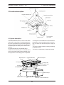
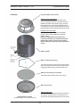
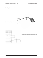
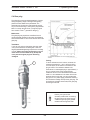
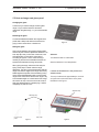
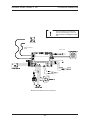
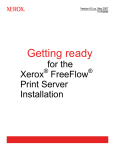
Diesel Cooker x100
Service Manual
08-05-2008
Webasto Diesel Cooker X 100
Table of Contents
1. General
1.1 Contents and purpose
1.2 Use of the cooker
1.3 Additional documentation
1.4 Safety notes and legal issues
1.5 Suggestions for improvements and changes
101
101
101
101
101
2. Function description
2.1 System description
2.2 Main components
2.3 Operating scheme
3. Technical Data
201
202
207
301
4. Failure detection
4.1 Trouble shooting chart
4.2 General failures
4.3 Failure blink codes
402
403
406
5. Updating and repair
5.1 Updating
5.2 Test program
5.3 Burner
5.4 Glow plug
5.5 Heat exchanger and glass panel
5.6 Pump Boost
6. Electrical connections
501
503
504
506
507
508
601
7. Maintenance and service
7.1 Basic maintenance
7.2 Control unit settings
701
703
Webasto Diesel Cooker X 100
1 General
1 General
1.5 Suggestions for improvements and
changes
1.1 Contents and purpose
Complaints, improvement suggestions or
corrections relating to this workshop manual should
be addressed to:
This workshop manual is designed to assist trained
personnel with repairing the Webasto Diesel Cooker
X 100.
Webasto Product North America, Inc.
Technical Documentation Group
15083 North Road
Fenton MI 48430
Phone: (800) 555-4518
Fax: (810) 593-6001
1.2 Use of the cooker
The Webasto Diesel Cooker is designed for use in
motorcaravans. It is not designed for use in boats.
1.3 Additional documentation
This workshop manual contains all the information and
instructions required for repairing the Webasto Diesel
Cooker X 100. If necessary the operating / installation
instructions may also be used.
You are also invited to fill out our online questionnaire
concerning our technical documentation and web
site at: www.techwebasto.com
1.4 Safety notes and legal issues
In principle, the general accident prevention regulations
and current works safety instructions are applicable.
Webasto Diesel Cooker X100 is tested by SGS, test
spesification standard EN 1:1998 + EN 60335-26:2003
Failure to follow the installation instructions and the
notes contained therein will lead to all liability being
refused by Webasto
The same applies if repairs are carried out
incorrectly or with the use of parts other than
genuine spare parts. You must read the operating
manual before starting the
heater for the first time.
101
Webasto Diesel Cooker X 100
2 Functions description
2 Functions description
2.1 System description
The Webasto Diesel Cooker X 100 is a safe diesel
cooker with no open flame. The exhaust gases are
led out of the vehicle through the exhaust gas tube,
which is inside the cooling air tube. The steam from
the exhaust gas will not stay in the vehicle to add
humidity.
As the diesel fuel burns, the released heat is
transferred to the ceramic plate. The hottest area is
on the round plate. Gentler heat is available on the
oblong extension. The heating power is adjustable.
a
Main cooking area
A cooling fan in the ventilation box ensures that the
temperature in the mounting space will not rise too
high. The warm air is led out through the cooling air
tube.
The cooker is ideally suited for cooking and heating
of all kinds of food.
The cooker is made entirely of stainless materials.
Hot plate indication lamp
Additional cooking area
Mounting piece
Exhaust gas tube
Fuel pump
Temperature sensor
Fuel needle
Glow plug
Overheat thermostat
Combustion air fan
Control unit
Burner chamber
Cable lead-through
Ventilation box
Cooling fan
201
Fuel hose lead-through
Webasto Diesel Cooker X 100
2 Functions description
2.2 Main components
Operating panel
The cooker starts to heat up automatically when the
power button is switched to ON position. The yellow
indicator lamp lights up as soon as the cooker is
switched on. The red combustion lamp will light up
when the combustion is stabilized in the burner,
about 2.5-4 minutes after the start-up.
Power indication lamp (yellow)
Combustion
indicator lamp
(red)
Power switch
Power
adjustment
High altitude
indication lamp
(orange)
High altitude switch
Start
Power
indication
lamp
1
Stop
⇓
⇓
Yellow
0
Combustion
Red
indication
lamp
Start-up 2.5-4 min Cooking
1
0
0,25 s
0,25 s
0,25 s
0,25 s
Run down phase about 5 min
Signal lights of operating panel during normal operation
202
Webasto Diesel Cooker X 100
2 Functions description
Fuel pump
Combustion air fan
The fuel pump is a combined transport, metering
and shut-off system for supplying fuel from the
vehicle’s tank to the cooker.
The voltage range of the burning fan may be altered
between 4.8 V and 10.7 V by changing the parameters; the adjustment range of the parameters is
4,000 mV – 11,000 mV. Check the voltage in the last
parameter file. During the first second of start-up the
control unit tests the fan’s motor. During the following second, the motor receives an initial impulse of 7
V from which the voltage is decreased to the minimum set forth in the parameters. The voltage will be
increased linearly towards the maximum during the
start-up cycle; the maximum will be reached in
approximately 4 minutes and 50 seconds after the
start-up cycle ends. The power control does not
work during this time. After the start-up cycle, the
burning fan adjusts itself from maximum to minimum
and minimum to maximum at a rate of 5 % per
second (20 sec. max. > min.).
The adjustment range for the pump’s pulsing is
0.5 sec. - 4.5 sec.; adjustment is linear. Check the
length of the pulsing in the last parameter file.
After turning the operating switch to the ON
position, the pump will be at a standstill for 30
seconds after which the pump’s pulsing will begin
to rise linearly towards the maximum setting; it will
reach the maximum 4 minutes and 50 seconds
after the start-up cycle ends. The power
adjustment will not work during start up cycle.
When you adjust the device from maximum to
minimum, the pump’s impulse interval will
immediately drop, step by step, to the value of the
minimum pulse interval (+ 0.5 sec.). After this, the
pulse will excellerate until it reaches the normal
pulse interval at the minimum output. In other
words, if the pulse interval at the maximum is 1
second and at the minimum 3 seconds, then the
pulse interval will decrease immediately to 3.5
seconds when adjusting from maximum to
minimum. It will rise from that point in 20 seconds
to 3 seconds.
Heat exchanger
The heat generated by the combustion process is
transferred to the air transported by the combustion
air blowers into the heat exchanger. There it gives
off heat to the ceramic glass panel. The exhaust gas
then exits through the exhaust gas tube and is
ducted outside the vehicle through the stainless
steel exhaust tube.
Glow plug
Heat exchanger
During the first second of ignition the glow plug
receives quick pulses, with which you can make
sure it is working properly. During the 2nd second,
voltage increases with a pulse ratio of 25 %. After 5
seconds, the pulse ratio increases to 70 %; and
after 15 seconds, the voltage increases to 100 %.
Programmed ignition monitoring will begin 15
seconds after start-up, before which there is only
mechanical protection.
HF
V
VH
H
WLR
WLR
UD
UD
H
WLR
UD
V
V
XO
OV
S
X
S
F
VH
VH
XO
S
XO
S
FN
XL
T
HF
F
VH
V
The principle of operation of the ignition voltage
203
Webasto Diesel Cooker X 100
2 Functions description
Temperature sensors
Hot plate indication lamp
The T4 circuit measures the voltage of the heat
sensor (thermocouple) and will light the red LED
light if the voltage exceeds the limit (10 mV).
Ten seconds after start-up the T4 will begin
recognizing the voltage.
The burning detection limit is 10 mV and it will be
raised 30 % at the same pace as the voltage rises.
The burning detector’s (red LED light) ignition
indicator is 10 mV and its shut-down indicator is 13
mV.
There is an 8-second delay from the time the
burning detector shuts off until the pump shuts
down. The lock-up detector will automatically reset
from the burning detector. The red LED light will
indicate whether or not the burning detector is
functioning. See 2.2 “Descriptions of flashing lights”.
An orange hot plate indication lamp lights on the
lower edge of ceramic plate when the plate is hot.
The hot plate indication lamp will light up
immediately after the start. The lamp will remain on
for 50 minutes (± 10 %) after the cooker has been
turned off.
Control unit
The control unit is the central component for
ensuring the cooker’s function and monitoring for
proper cooker operation.
If a fault occurs, an error code will be output in the
LEDs of the operating panel by various flashing
sequences.
In addition, the heater’s parameters and running
hours can be checked using a personal computer.
T3 is a overheat thermostat. When the temperature
rises over 150° C (302° F) power is removed from the
fuel pump and the unit goes into a cooling phase.The
thermostat will automatically return to the On position
after the unit cools.
Note! You must be sure you have ESD
protection while handling the control unit.
Static electricity can damage the control
unit.
Control panel
Wires for control
panel
Thermo element
Electrical connections for the control unit
204
Webasto Diesel Cooker X 100
2 Functions description
Cooling system
Í
The cooker is cooled down by a ventilation box located
under the cook top. On the front side of the ventilation
box is an axial fan wich draws fresh air into the box.
Hot air is blown away from box through an outlet which
is located on the bottom of the box. The exhaust outlet
is located inside the fresh air tube (= a coaxial hose).
This means that fresh
air is also cooling down the exhaust gases. See also
installation manual : Exhaust system.
Í
205
Webasto Diesel Cooker X 100
Burner
2 Functions description
Thermal radiator for the burner
Detaching the thermal radiator:
There are two locking plates on the inside of the
burner’s “perforated” cylinder which have been spot
welded to the sides of the cylinder. Prying one of the
locking plates with a screwdriver against the side of
the cylinder, for example, should be enough to free the
thermal radiator and pull it up.
Installing the thermal radiator:
Push the thermal radiator inside the “perforated”
cylinder until the locking plates lock the thermal
radiator in place.
Note! The locking plates must be bent a bit
crosswise before you can assemble the thermal
radiator back in place. This will ensure that the
thermal radiator will stay in place during transport
as well.
Through pipe for
the temperature
sensor (T4)
Burner cylinder
Installation
hole for glow
plug
Installation hole
and needle
support for the
fuel needle
Burner’s bottom mat spring
The bottom mat spring for the burner ensures that the
bottom mat stays on the bottom of the burner preventing the glow plug from going under the bottom mat.
Bottom mat of the burner, Ø 85 mm
(Delivered together with the bottom mat spring.)
Base of the burner
Complete burner cylinder
(Includes all parts you see in the picture.)
Removing deposits:
Mechanically remove deposits by using a screwdriver,
for example. Scrape all of the inner surfaces of the
burner clean and replace the bottom mat of the burner.
206
Webasto Diesel Cooker X 100
2 Functions description
2.3 Operating scheme
How the device works
Turn the device on by turning the switch on the
control panel to the ON position. The yellow LED
light next to the switch will illuminate signifying that
the device is on. If the yellow LED light flashes at
intervals of one second, then the device is not
receiving enough voltage. The under-voltage limit is
10.7 V.
Start
Power
indication
lamp
1
Stop
⇓
⇓
Yellow
0
Combustion
Red
indication
lamp
Start-up 2.5-4 min Cooking
1
0
0,25 s
0,25 s
0,25 s
0,25 s
Run down phase about 5 min
Signal lights of operating panel during normal operation
207
Webasto Diesel Cooker X 100
2 Functions description
12 V
The yellow LED light is ON
Main switch
off
on
240 sec. (alterable parameter)
Glow Plug
off
max
Combustion air
fan
min
4 min. 50 sec.
max
Cooling fan
min
4 min. 50 sec.
max
Fuel pump
min
4 min. 50 sec.
20 sec.
30 sec.
Temperature
sensor (T4)
The red LED light is ON
Rise: 30%
10 mV
0
The red LED light is
flashing
Burning indicator limit
on
5 min.
After-cooling
off
Table illustrating the device´s priciple of operation
208
Webasto Diesel Cooker X 100
3 Technical Data
3 Technical Data
Except where limit values are specified, the technical data listed in the table refer to the usual heater
tolerances of ±10% at an ambient temperature of
+20° C (68° F) and at the rated voltage and in rated
conditions.
Electrical components
The control unit, combustion air fan, cooling fan, fuel
pump, glow plug and operating element are designed for 12 V. The components overheat thermostat and temperature sensor are not designed for a
specific voltage.
Fuel
The diesel fuel specified by the manufacturer must
be used. It has to comply with the normal quality
available on the market.
.
We know of no negative influences due to additives.
If you change to low-temperature fuel, the cooker
must be operated for approx. 15 minutes so that the
fuel system is filled with the new fuel.
301
Webasto Diesel Cooker X 100
THE DEVICE´S
3 Technical Data
FUNCTION
TECHNICAL VALUES
Dimensions
466 x 316 x 205 mm
Weight
~ 8 kg
Size of replacement air aperture
(minimum area)
100 cm²
Heating capacity
(calculated)
Max.
adjustment range
0.9 ... 1.9 kW
Fuel
Diesel
Longest permissible length of fuel hose
Highest permissible rise of fuel hose
(without adjusting the pump)
8m
1.5 m
Fuel consumption
Max
Min
190 ml/h
90 ml/h
(0.16 kg/h)
(0.07 kg/h)
Pump´s pulse intervals, 1/fpump
Max
Min
1.45 sec.
3.00 sec.
(see parameter file)
(see parameter file)
Nominal operating voltage
12 V DC
Functioning voltage range
10.7 ... 15 V
Currency consumption
0.3 A , upon ignition 8 A
Glowing time
240 sec.
(see parameter file)
~ 9.5 V
~ 5.5 V
(see parameter file)
(see parameter file)
Burning fan´s voltage, Ufan
Max
Min
Longest permissible length of the
combustion hose
1.9 m, straight downwards 1.2 m
(ø 28 mm and ø 60 mm)
CO2 of the combustion (calculated)
Max
Min
6 ... 7 %
4 ... 5 %
Temperature of the combustion, T
Max
Min
~ 265° C (509° F)
~ 135° C (275° F)
< 20 ppm
< 100 ppm
Combustion´s carbon monoxide content, Max
CO
Min
Combustion´s soot index
Max
Min
0
0
Air coefficient of the combustion
Max
Min
~ 2.5
~ 3.4
Combustion´s oxygen contect, O2
Max
Min
11.5 ... 13.0 %
14.0 ... 15.5 %
302
Webasto Diesel Cooker X 100
4 Failure detection
4 Failure detection
This section describes how to identify and remedy
faults on the Webasto Diesel Cooker X 100.
If a fault occurs, an error code will be output via the
LED’s of the operating panel.
CAUTION
Troubleshooting work demands precise knowledge
of the structure and theory of operation of the
various components and must be carried out by
trained personnel only.
CAUTION
The troubleshooting guide is restricted to the
localisation of defective components. The following
potential sources of malfunctions should always be
checked so that they can then be excluded as the
cause of the particular fault:
• Corrosion on plugs
• Loose plug contacts
• Poor crimp contacts on plugs
• Corroded cables and fuses
• Corroded battery terminals
If you wish to check individual components, the
electrical plug connectors on the control unit must
be disconnected. Conduct a function test in the
vehicle after correcting each fault.
401
Under 10,7 V
402
Yes
Check the condition of the
battery and power supply
cables. Charge the battery, if
necessary.
Check the battery voltage.
The battery voltage must be
at least 10.7 V.
Check the power supply and
control unit fuses.
Check to see if the electric
wires are connected properly;
check the couplings and main
switch.
Check the control panel and
the control panel´s cable.
No
Is the device receiving
currency ?
(1)
The stove does not
start up (after two
tries).
(2)
(4)
Check the control unit´s
jumper settings.
Check the control unit´s
couplings.
Check the control unit.
CONTROL UNIT
(1)(2)
The pump is worn out or dirty
and is unable to take in fuel.
The connection of the suction
hose to the pump is not
completely tight and the
pump is sucking in air.
The pump receives impulses
and the piston is moving, but
the fuel is not moving through
the hose.
The pump receives impulses,
but the pump´s piston is not
moving. (You can see the
movement of the piston in the
pump´s vibration and the
slight clicking sound it makes.
Change the control unit.
Defective control unit.
Change the pump.
Check the coupling and, if
needed, tighten it.
Clean the fuel needle and
burner. Change the filter.
Check to see if the fuel
needle or filter is clogged.
Check the pump. (You can
try to move the pump´s piston
by tapping the side of the
pump a bit; if necessary,
change the pump).
Check the pump´s wiring and
the condition of the overheating protector.
(3)
The stove is out of fuel or
there is not enough fuel for
the end of suction hose to
reach the fuel in the tank.
(5)
There is water in the
combustion hose.
(4)
The lead-through is closed.
(5)
There is water in the fuel.
(5)
Low-grade fuel.
OTHER REASON
(2)
Defective glow plug (light
flashes signifying defect).
The glow plug is not receiving
enough voltage (it does not
get hot enough).
(2)(3)
GLOW PLUG
The pump is not receiving
electric impulses. The red
LED light on the control unit
is not flashing.
Check the control unit.
The stove smokes
when starting up.
(3)
PUMP
Unlocking the lock:
1. Turn the switch to the ON position
(light flashes when in locked position).
2. Unplug the main electric cable (light
stops flashing).
3. Plug the main electric cable cack in
(the yellow LED will turn on for 1-3 sec.).
4. When the yellow LED light has shut of,
turn the switch to the OFF position.
LIGHT FLASHES WHEN IN LOCKED
POSITION
The stove does not do
anything.
(1)
Add more fuel.
Check to see if there is water
in the curves of the
combustion hose (water
trap).
Open the lead-through.
Filter it or change the fuel.
Change the fuel.
Make a visual check. (The
glow plug often changes
shape when it breaks.)
Check the brand and type of
glow plug you are using. Only
use original Wallas glow
plugs.
Check the couplings.
Make sure that the crosssectional area (mm²) is
sufficient in size.
The stove suddenly
stops while running.
(4)
(5)
The burning fan does not
rotate (light will flash
signifying defect), or it rotates
too slowly.
BURNING FAN
(2)
The burner must be opened
and cleaned.
The burner has become
sooty.
BURNER
(2)(4)(5)
Burning is irregular /
the stove smokes.
(5)
Webasto Diesel Cooker X 100
4 Failure detection
4.1 Trouble shooting chart
Webasto Diesel Cooker X 100
4 Failure detection
4.2 General failures
Failure symptom
Cooker does not respond at all.
Possible reason
Is operating voltage under 10.7 VDC ?
(Measure the voltage from control unit’s
voltage connector).
Check the main cable connections
and the main switch.
A) Yes.
Check the control unit, control
panel and control panel cable.
Check fuses on main cable and on
control unit.
B) No. See how to repair.
Cooker does not start.
Note: After two failed start attempts
the cooker is in lock-up state !
How to repair
Check the battery voltage.
Battery voltage must be over 10,7 VDC.
Pump
Pump does not get get pulses.
Red LED does not blink on control board.
Check the control unit.
Check the pump wires / wiring and over
heat protector’s condition.
Removing Lock-Up:
1. Turn the cooker ON (lock-up LED
is blinking).
2. Unplug the main cable (blinking
goes OFF).
3. Plug in the main cable (yellow LED
blinks couple of times).
4. When yellow LED goes OFF, turn
cooker OFF.
Pump get’s the pulses, but pump piston
does not move.
(A small ticking sound can be heard when
the piston moves)
Check the pump.
(Sometimes a small tapp on pump’s side
help’s to relase the piston, if necessary
change the pump).
Pump get’s pulses and piston moves, but
fuel does not move inside the fuel line.
Check if the fuel needle or fuel filter is
blocked.
Fuel line joint to the pump is loose and
pump get’s air.
Check and tighten joint.
Pump is worn or dirty and can not pump
fuel.
Replace the pump.
Glow plug
Glow plug does not get sufficient voltage.
(Glow plug is not hot enough).
Check that the main cable cross area
(mm²) is large enough. Check also all
connections.
Glow plug is faulty.
(fault blinking).
Visual check, (often the plug changes
form when faulty).
403
Webasto Diesel Cooker X 100
4 Failure detection
Combustion air blower
Combustion air blower does not run.
(Fault blinking).
Measure blower’s voltage,
(compare to the parameter table).
Replace the combustion air blower.
Control unit (PCB)
Control unit faulty.
Replace the Control unit.
Temperature sensor T4
Temperature sensor voltage does not rise
during start up.
Measure the voltage approx. 5 minutes
after the start up, voltage must be over
13mV, (sensor wires attached to the board).
Check the temperature sensor.
Other cause
Cooker is smoking during starting phase.
Bad fuel quality.
Change the fuel.
Water in fuel.
Change the fuel.
Exhaust lead through blocked.
Remove blockage.
Water inside the exhaust pipe.
Remove the water. Make sure that there is
no water lock, (water in pipe bend’s).
No fuel.
Refill fuel tank.
Glow plug voltage is too low, (glow plug is
not hot enough).
Check that the main cable cross area,
(mm²), is large enough. Check also all
cable connections and connectors.
Glow plug faulty,
(fault blinking)
Visual check, (often the plug changes form
when faulty)
Water in fuel.
Change the fuel.
Water inside the exhaust pipe.
Remove the water. Make sure that there is
no water lock, (water in pipe bend’s).
404
Webasto Diesel Cooker X 100
Cooker goes OFF by itself.
4 Failure detection
No fuel.
Check and add fuel if necessary.
Check the fuel pump’s operation.
Battery voltage too low, must be more
than 10.7 VDC.
Check the battery condition and main
cable connections. Recharge the battery
if necessary.
Water in fuel.
Change the fuel.
Water inside the exhaust pipe.
Remove water. Make sure that there is
no water lock, (water in pipe bend’s).
Hard wind pressure on exhaust lead
through vent.
Turn the vehicle so that the wind does not
hit directly the lead through vent.
Cooker over heated.
Check the free air flow around the cooker.
Measure the fuel consumption, adjust if
needed. Max 190 ml, Min 90 ml
Unstable combustion / cooker
smokes.
Burner is sooty.
Clean the burner.
(see chapter burner)
Water in fuel.
Change the fuel.
Bad fuel quality.
Change the fuel.
Water inside the exhaust pipe.
Remove the water. Make sure that there
is no water lock. (water in pipe bend’s.)
Wrong fuel consumption.
Measure the fuel consumption, adjust if
needed. Max 190 ml, Min 90 ml
Check the fuel needle and the filter.
Burner is sooty.
Clean the burner.
(see chapter burner)
405
Webasto Diesel Cooker X 100
4 Failure detection
4.3 Failure blink codes
Signal lights in case of malfunctions.
ON
Glow plug
problem
Combustion
air fan
problem
Cooling
air fan
problem
Undervoltage
Yellow
OFF
0.125 s
2s
0.125 s
2s
0.125 s
ON
Yellow
OFF
0.125 s 0.125 s 0.125 s
2s
0.125 s 0.125 s 0.125 s
2s
ON
Yellow
OFF
0.125 s 0.125 s 0.125 s 0.125 s 0.125 s
2s
0.125 s 0.125 s 0.125 s 0.125 s 0.125 s
ON
Yellow
OFF
Locking
after 2
unsuccessful
starts.
0.25 s
0.25 s
0.25 s
0.25 s ...
ON
Yellow
OFF
ON
Red
OFF
0.125 s 0.125 s 0.125 s 0.125 s ...
Opening the locking:
1. Switch the power ON (lock blinking).
2. Disconnect the main power cord (blinking stops).
3. Reconnect the main power cord (the yellow LED lights up for 1-3
seconds).
4. When the yellow LED has gone out, switch the power OFF.
Overheat
ON
Red
OFF
Lights after
failure
signal
0.25s
0.25s
0.25s
0.25s
ON
Red
OFF
0.125s
30s
0.125s
The red lamp begins blinking when failure signal has lasted for 5
minutes.
406
30s
2s
Webasto Diesel Cooker X 100
4 Failure detection
Descriptions of the flashing LED lights beginning from XPS v 1.2.
Leds on the control panel
Third attempt to start the device
Yellow LED
After two unsuccessful attempts to start the device, the
third attempt will lock it. In this case all LEDs will begin
to flash at a quick pace. The LEDs flash on and off for
a duration of 0.125 seconds.
If the device does not shut off in the heating phase,
after the initial testing, due to a defect, then the
start-up will continue and the yellow LED light will
illuminate and remain on continuously.
Incorrect device parameters
Initial testing
One quick flash of the yellow LED indicates that
there is a malfunction in the glow plug. The LED light
will be on for 0.125 seconds and off for two seconds,
after which it will repeat the sequence. The glow plug
defect may be due to a short circuit or complete
breakage.
Two quick, consecutive flashes of the yellow LED
light indicate a malfunction in the burning fan. In this
case, the LED is on for 0.125 seconds at first, then it
is off for 0.125 seconds and then on again for
another 0.125 seconds. After the second flash, the
LED is off for two seconds before it makes a new
double flash. The malfunction is either due to a short
circuit or the routing for the burning fan is completely
broken.
Three quick, consecutive flashes of the yellow LED
light indicate a malfunction in the main fan (other
names include rotary fan, ventilation fan or cooling
fan). Each flash lasts 0.125 seconds and the time
between two consecutive flashes is also 0.125
seconds. After the third flash the LED light is off for
two seconds before it makes a new triple flash. The
main fan’s malfunction is either due to a short circuit
or the routing for the main fan is completely broken.
The main fan should be tested in the ventilation
stage as well.
Testing the power control: the flashing speed of the
yellow LED light only changes according to the
potentiometer setting when the pin pair, S1, is
closed. When S1 is open, the speed of the flashing
correlates to the minimum of the potentiometer
regardless of the potentiometer’s actual position.
If the device’s parameters are not set within the
permitted range of values at the point of start-up,
then the device will not start. However, the attempt
to start the device counts towards one start-up. All
LEDs will begin to flash in a circulating pattern; each
LED light will be on for a duration of 0.125 seconds.
All LED lights shut off for a duration of 0.125
seconds between the time the first LED light shuts
off and another LED turns on. The LEDs circulate in
the following order: the yellow LED light and the red
LED light. During normal use, incorrect device
parameters should not occur in the device’s memory
because the XP Link terminal programme does not
allow users to enter incorrect parameters into the
device’s memory.
Test phase
When the thermostat pin pair, S1, is closed, the
yellow LED light flashes according to the
potentiometer setting during the test phase. In this
case, when the potentiometer is at the minimum, the
LED light flashes on and off for a duration of 0.5
seconds. When the potentiometer is at the
maximum, the LED light flashes on and off for a
duration of 0.05 seconds. The LED light flashes on
and off for a duration of 0.5 seconds when S1 is
open.
Indication of a malfunction in the operating voltage
A uniform flashing of the yellow LED light indicates if
and when the battery voltage has decreased below
10.7 V. The LED light is on for 0.25 seconds, turns on
and off alternatingly.
407
Webasto Diesel Cooker X 100
4 Failure detection
Red LED
Burning indicator and after-cooling
Incorrect device parameters
In the heating phase, when the burning indicator has
turned on during glowing or ignition, the red LED light
will illuminate at that point and remain illuminated
continously. The LED light will react without any delay
if the burning indicator shuts off. The actual
malfunction that caused the burning indicator to shut
off will be locked 5 seconds after the burning
indicator fails to work.
If the device’s parameters are not set within the
permitted range of values at the point of start-up,
then the device will not start. However, the attempt to
start the device counts towards one start-up. All
LEDs will begin to flash in a circulating pattern; each
LED light will be on for a duration of 0.125 seconds.
All LED lights shut off for a duration of 0.125 seconds
between the time the first LED light shuts off and
another LED turns on. The LEDs circulate in the
following order: the yellow LED light and the red LED
light. During normal use, incorrect device parameters
should not occur in the device’s memory because the
XP Link terminal programme does not allow users to
enter incorrect parameters into the device’s memory.
During after-cooling, the LED light will begin to
uniformly flash once the burning indication limit has
been broken.
The LED will flash on and off for a duration of 0.25
seconds. After-cooling lasts for approximately five
minutes.
Flashing due to over-heating
During the heating phase, when the alarm indicating
over-heating has locked as the result of a 5-second
over-heating situation, the red LED light will
uniformly flash. The LED will flash on and off for a
duration of 0.25 seconds. The LED light will shut off
5 minutes after the start of the flashing due to overheating.
Testing phase
The red LED light will be on during the testing phase
when the voltage measured on the T4 circuit
exceeds the 5 mV threshold. Correspondingly, the
LED will shut off when the measured value drops
under 5 mV.
Flashing light after the flashing due to a malfunction
When the flashing light due to intial test
malfunctions, as presented in the “Initial testing”
section, has lasted 5 minutes, the yellow LED light
will shut off and the red LED will begin to flash at
intervals of 30 seconds. Each flash during the 30
seconds lasts 0.125 seconds.
Third attempt to start the device
After two unsuccessful attempts to start the device,
the third attempt will lock it. In this case all LEDs will
begin to flash at a quick pace. The LEDs flash on
and off for a duration of 0.125 seconds.
408
Webasto Diesel Cooker X 100
5 Updating and repair
5 Updating and repair
WARNING
The cooker must not be operated in enclosed areas
such as garages and workshops without an
emissions extraction system.
5.1 Updating
There may be a maximum of 32 parameter files
programmed on the control unit.
The parameters may be put on the control unit either
one at a time or all together.
XPS software
Download the programme onto your computer; the
name of the programme is xplink.exe. Hook a datatransmission cable between the computer and
control unit. The length of the cable is 1.5 m and you
hook it to the serial port. If your computer does not
have a serial port, then the data-transmission cable
must be connected via an USB adapter.
17: Device 17
Make sure you always use the latest
parameters.
Make sure the USB adapter you
use is compatible with your operating system.
For choosing the device
9500
Parameter files may be saved
from the file or manually edited
5500
For choosing the PC’s port
11000
9500
From the control unit to the PC
1450
From the PC to the control unit
3000
Checking this box enables you to
choose all devices at one time
240
Amount of operating hours
Signifies what programme
version is being used on
the control unit
Figure 1
501
Webasto Diesel Cooker X 100
5 Updating and repair
1.
Copy all files from the CD on to your computer’s hard
disk to the location of your choice.
8.
There are two ways to update a single device:
2.
Install the PC cable into an available COM port. You
may need a USB-COM adapter to install the cable if
your laptop does not have a COM port.
(Note! Make sure you choose the right USB adapter)
3.
Connect the PC cable to the XPS card as illustrated in
Figure 2.
Note! The coupler has 5 studs in use; one stud has
been soldered shut: There is only one way you can
connect the PC cable to the control unit.
4.
Connect the electrical and control panel wires to the
control unit and turn the stove on.
5.
Start the programme by double-clicking on the
xplink.exe file, located on your computer’s hard disk.
XPlink will open up as illustrated in Figure 1(see
previous page).
6.
Choose the correct COM port (COM1 ...COM4,
depending on your computer’s settings).
When you have succeeded in getting the correct COM
port to work, the control unit’s amount of operating
hours and programme version will be displayed on the
Xplink operating system (Figure 1).
8.1
You can update all parameters by clicking on “Choose
all”.
Click on “Export”
The parameters of all devices are updated at the
same time; this takes just a few moments. When the
parameter update has succeeded, the text “...file
transfer ok...” will appear on the screen after a few
seconds. If the data transfer has been unsuccessful,
the operating sustem will display an error message on
the screen.
8.2
You can also update the parameters of just one
device. In this case, DO NOT click on “Choose all”.
Next, choose the appropriate device from the popdown menu.
“Device 17”.
Click on “Export”.
Loading may take 1 to 2 seconds.
When the parameter update has succeeded, the text
“...file transfer ok...” will appear on the screen after a
few seconds. If the data transfer has been
unsuccessful, the operating system will display an
error message on the screen.
9.
When the parameter update has been successful,
detach the PC cable from the control unit.
10.
7.
Click “File” > Open > AI.xpd (always use the last file
that was used)
You can use the new parameters immediately.
PC cord connector
PC connection on XPS card
Figure 2
502
Webasto Diesel Cooker X 100
5 Updating and repair
5.2 Test program
A device named “Test”
The test device assists the maintenance person
when investigating the condition of the control unit,
e.g. directly from the maintenance coupler J6.
The test device is a device / in the device parameter
selection X1, Device 1. You can get to Device 1 by
detaching all jumpers from the pin pairs (S2 – S6).
The test device assists the maintenance person
when investigating the condition of the control unit,
e.g. directly from the maintenance coupler J6.
The following values have been programmed as the
test device:
-
“Maintenance”
coupler
7 V for the main fan´s motor
7 V for the burning fan´s motor
Glow on normally and stays on, 11 V
4 clicks from the pump
T4 voltage > 5 mV !
Burning indicator LED light turns on
T4 voltage decreases < 5 mV !
Burning indicator LED light shuts off
Flashing of the yellow LED 1 Hz when
the potentiometer is at the minimum
Flashing of the yellow LED 10 Hz when
the potentiometer is at the maximum
Coupler for device
selection
If you do not get these values, the control unit is
defective.
Measurements from the control unit
You can measure the following values from the J6
connector while the unit is running:
J6-1, Operating voltage
J6-2, Quick pumping
J6-3, Glow plug voltage
J6-4, T4 voltage (after amplifier)
J6-5, T3 voltage (pulse)
J6-6, Pump pulse
J6-7, Voltage for burning fan
J6-8, Voltage for main fan
J6-9, GND
Connection diagram for
maintenance coupler
503
Webasto Diesel Cooker X 100
5.3 Burner
5 Updating and repair
Thermal radiator for the burner
Detaching the thermal radiator:
There are two locking plates on the inside of the
burner’s “perforated” cylinder, which have been spot
welded to the sides of the cylinder. Prying one of the
locking plates with a screw driver against the side of
the cylinder, for example, should be enough to free the
thermal radiator. Pull the thermal radiator up to remove.
Installing the thermal radiator:
Push the thermal radiator inside the “perforated”
cylinder until the locking plates lock the thermal
radiator in place.
Note! The locking plates must be bent a bit
crosswise before you can assemble the thermal
radiator back in place. This will ensure that the
thermal radiator will stay in place during transport
as well.
Through pipe for
the temperature
sensor (T4)
Burner cylinder
Installation
hole for glow
plug
Installation hole
and needle
support for the
fuel needle
Burner’s bottom mat spring
The bottom mat spring for the burner ensures that the
bottom mat stays on the bottom of the burner preventing the glow plug from going under the bottom mat.
Bottom mat of the burner, Ø 85 mm
(Delivered together with the bottom mat spring.)
Base of the burner
Removing deposits:
Mechanically remove deposits by using a screw driver,
for example. Scrape all of the inner surfaces of the
burner clean and replace the bottom mat of the burner.
Complete burner cylinder
(Includes all parts you see in the picture.)
504
Webasto Diesel Cooker X 100
5 Updating and repair
Installing the fuel needle
The direction of the slanted tip of the needle in the
burner must be considered when installing the fuel
needle.
The slant of the needle goes towards the upper edge
of the burner.
505
Webasto Diesel Cooker X 100
5 Updating and repair
5.4 Glow plug
The glow plug consumes approximately 8 A of power
during the glowing stage. The length of the glowing
phase is the time stated in the parameters. The
temperature of the glow plug rises extremely quickly.
As you can see from Fig. 5, the tip of the plug reaches
850°C in twenty second’s time. (The glow plug we
have used is in the 2nd generation category.)
Malfunction:
The glow plug may experience a malfunction as a
result of thermal overload. In this case, the resistance
wire will either break or short circuit with the shell of the
glow plug.
Þ
Installation:
If you are only going to change the glow plug, make
sure you are careful in connecting the + wire. The
largest permissible tightening torque for the mounting
is 5 Nm. When connecting the mounting nut, you
must hold on to the bottom nut (1) to keep the
inner parts of the glow plug from becoming
damaged.
Testing:
To see if resistance wire is broken, measure the
resistance between the + and – terminals with a
circuit analyzer. There will be no resistance if the
plug is broken. The resistance between the
terminals of an undamaged plug is approximately 1
ohm. In case of a short circuit, measuring the
resistance will not uncover the malfunction because
there is a 1 ohm resistance in the wires of the circuit
analyzer alone. In this case, you can hook the glow
plug up to a 12 V power supply (remember the fuse!)
and monitor the heating of the tip of the glow plug. The
tip should turn red within 20 seconds, if the glow plug
is working as it should.
1.
Protect your eyes and be
exremely careful when connecting
the glow plug to the power supply.
A defective glow plug may spatter
melted metal through the shell.
506
Webasto Diesel Cooker X 100
5 Updating and repair
5.5 Heat exchanger and glass panel
Changing the glass
In the event you need to change a broken glass
range or if you need to reach the structures
underneath the glass range, i.e. you must break the
range.
Detaching the glass
Cut the weld adhesive between the range and the
profile with a sharp knife while at the same time
prying it with a screw driver or similar tool.
Figure 2:
Gluing the glass
Clean the old adhesive and grease off the profiles
well and dry the surfaces. Spread the adhesive in an
even strip (Ø 4 mm) in the niche of the front, back
and side profile. Go around the entire device
according to Figures 1 and 3. Press the range
carefully in place such that the adhesive does not
squeeze from between the range and profile.
When gluing the range, take note of the way the
spring of the banjo, located under the range,
depresses. The spring must depress along with the
range such that the edges of the range have evenly
settled against the profiles. Place something heavy
on the range that distributes evenly over the entire
range for the entire time it takes for the range to dry.
Concentrated weight on a certain area of the range
will cause it to warp. You have six minute’s time to
apply the adhesive before it starts drying. It will be
completely dry after 24 hours.
Adhesive
The adhesive used is Loctite® 5368.
Store the adhesive in room temperature.
Location of the adhesive in the profiles and
adhesive cleat:
The strip of adhesive is approximately 4 mm thick
and goes around the entire device in the place
illustrated in the Figure 1.
Adhesive strip
Adhesive strip
Front and back
profile
Side profile
Figure 1:
Figure 3:
507
Webasto Diesel Cooker X 100
5 Updating and repair
5.6 Pump Boost
The Pump Boost (PB) function has been designed
to facilitate filling the fuel hoses during installation
and maintenance.
Connect the PB by turning the maintenance person’s switch to the vent position and connecting the
J6 pins 1 and 2 of the maintenance coupling. The
pump will click once and by holding the pins together
for at least two seconds, the PB will work. There is
no vent position on the control panels of stoves.
The integrator stops the PB after the pump has
pumped 300 times; by opening the studs, the pump
will pump another 300 times. The PB will stop immediately if you open the pins. If you want to start the
PB again, turn the switch to the 0 position (> 1sec.).
The PB works when the operating voltage is more
than 11 V and the over-heating protector T3 is not on.
The PB function may only be
used in situations where the
device is completely “cold” or if
the fuel hose is empty.
508
Pump Boost
pins 1 and 2
Webasto Diesel Cooker X 100
6 Electrical connections
6 Electrical connections
Note! You must be sure you have ESD
protection while handling the control unit.
Static electricity can damage the control
unit.
J6, Test pin header
X1 - S2
X1 - S3
X1 - S4
X1 - S5
X1 - S6
X1 - S7
X1, PC connec. X1 - S8
X1 - S9
J6-1, Operating voltage
J6-2, Speed pumping
J6-3, Glow plug voltage
J6-4, T4 voltage
J6-5, T3 voltage (pulse)
J6-6, Pump impulse
J6-7, Burning fan voltage
J6-8, Main fan voltage
J6-9, GND
J5-1, heating “ON”
J5-2, ventilation “ON”
J5-3, + 12 VDC
J5-4, power control
J5-5, power control
J5-6, yellow LED light
J5-7, green LED light
J5-8, red LED light
X1, Device selection
S11, Flame monitor switch,
T4 (with jumper),
thermostat (without jumper)
J10-1, T4 thermocouple / thermostat - (green)
J10-2, T4 thermocouple / thermostat - (white)
J13-4, Main fan +
J13-3, Main fan J13-2, Over-heating protector(for the blower lid)
J13-1, Over-heating protector(for the blower lid)
J14-1, vuoristokytkin
J14-2, vuoristokytkin
J14-3, + 12 VDC
J14-4, GND
J12, GND
J9-1, Room thermostat
J8-3, Glow plug GND
J9-2, GND
J8-2, Glow plug voltage
J9-3, Burning indicator
J8-1, Glow plug +
J9-4, Timer “ON”
J9-5, + 12 V
J9-6, GND
J1-1, Operating voltage +
J1-2, Operating voltage -
J4-2, Burning fan J4-1, Burning fan +
S1, Room thermostat
Follows power control (with jumper)
S1 does not normally have a jumper; it has been
replaced with the J9-1 / J9-2 wire loop.
J2-4, T3 over-heating protector
J2-3, T3 over-heating protector
J2-2, Pump
J2-1, Pump
S10, Mountain switch
Mountain setting (with jumper)
Outer connections of the control unit
601
Webasto Diesel Cooker X 100
6 Electrical connections
Note! You must be sure you have ESD
protection while handling the control unit.
Static electricity can damage the control
unit.
Control panel
Wires for control
panel
Thermo element
Electrical connections for the control unit
602
Webasto Diese Cooker X 100
7 Maintenance and service
7 Maintenance and service
7.1 Basic maintenance
The cooker shall be serviced every two years by an
authorized service center.
In case of intensive use, replace the fuel filter once a
year.
Consider the following before taking measurements:
- You can begin to take verifying measurements only
after the device has heated up thoroughly, i.e.
approximately 10 min after ignition.
- The battery voltage must be at 12 -14 V while
taking measurements. A battery or stabilized directcurrent supply should be used for supplying power. A
battery charger or rectifier can not be used because
the device will not function properly with them.
- A dish should be set on the left-hand burner when
the stove has been on at full power for a period of 15
minutes. Otherwise, the stove will over-heat and
obtaining normal measurements will be impossible.
The suction height (from the top of
the measuring glass to the bottom
of the device) must be 30 - 60 cm
or, more accurately, the same
suction height as in the actual
installation.
Later, as the pump gets older, it may raise the
amount of fuel input by 5 - 10 %. Therefore, you
should always make a verifying measurement of the
fuel input when servicing the device or changing the
pump.
A Fuel input measurement
1.
Turn on the device.
2.
Adjust the device to maximum.
3.
Figure out how much fuel is being consumed
by measuring the fuel consumed during a
period of 6 min. using a 50 or 100 ml
measuring cylinder. When multiplying the
result by 10 you’ll get the value ml/h.
If the fuel input differes from the nominal value (see
technical information), adjust the input according
adjustment instructions.
B Fuel input adjustment
1.
Turn on the device.
2.
Adjust the device to maximum.
3.
About 5 minutes after start-up, measure the
pump’s input at maximum and adjust it to the
correct value using the “PUMP” trim, which is on
the card; the adjustment range is approximately
±5%
a. Turning the trim counter-clockwise will
decrease the yield, turning the trim clockwise
will increase it.
b. Measure the fuel input again.
Maintenance procedure:
1. Clean the burner
Open the burner according the instructions in 3.4.
Change the bottom mat if needed.
2. Check the glow plug
See malfunction and testing of the glow plug in 3.2.
Change the glow plug if needed.
3. Measure the fuel consumption
The fuel pump functions with electric pulses created
by an electronic pulse generator. You can hear the
pump running by the soft “thumping” sound it makes.
The more rapid the pulses (shorter pulses) are, the
more fuel the pump delivers. The ratio between the
pulse interval and the amount of fuel is constant. The
pump is adjusted to fixed volume at the factory,
therefore all pumps provide the same amount of fuel
within the same pulse interval.
C Malfunction of the pump
Malfunctions in the pump may be caused by dirt buildup in the valves or a damaged valve disc. Even a small
particle may prohibit the pressure gradient, needed for
pumping, from forming, especially when starting the
device for the first time, when the pump does not
contain fuel. In this case, you can decrease the
pumping pressure gradient by putting the suction end
of the fuel hose in a bottle containing fuel, for example.
Then, raise the bottle to the same level of the heater or
above it.
Change the pump if needed.
701
Webasto Diese Cooker X 100
7 Maintenance and service
4. Analyze the O2 and CO2
5. Soot test
An O2 analysis reveals more quickly the reason for
impure burning. The O2 analysis should be performed
with a meter intended for the purpose.
The soot test determines whether the combustion is
pure.
You can perform the test with a
Combustion meters have an oxygen cell, which
measures the O2 value. The device numerically
changes the value to the CO2 value, which is used
universally in service shops. There are differences in
calculation formats; a more precise test result can be
achieved using the O2 value.
A
CO-meter (you can compare the result to the
nominal value in technical information)
B
Soot test pump
A CO2 value that is too high indicates an excess in
fuel input, not enough combustion air, an air gap in
the burner, or a defective burning fan. A CO2 value
that is too low indicates that the device is not getting
enough fuel or there is too much combustion air.
See the nominal value in technical information. If the
value differes make the adjustment.
Combustion air adjustment
A
Adjust the device to minimum and let it run at
the minimum for 10 min to reach the operation temperature. When the device has
reached its minimum operation temperature,
measure the combustion and, if needed,
adjust the minimum rotation speed of the
burning fan to “MIN” with the trim.
a. Turning the trim counter-clockwise will
decrease the rotation speed of the burning
fan, turning it clockwise will increase the
rotation; the adjustment range is approximately
± 5 %.
b. Measure the combustion again.
B
Adjust the device to the maximum and let it
run for 10 min to reach the operation tem
perature. When the device has reached its
maximum operation temperature, measure
the combustion and, if needed, adjust the
maximum rotation speed of the burning fan
with the “ANGLE” trim.
a. Turning the trim counter-clockwise will
decrease the rotation speed of the burning
fan, turning it clockwise will increase the
rotation; the adjustment range is approxi
mately ± 5 %.
b. Measure the combustion again.
Instructions to use of soot test pump
Place the test pump’s suction hose into the
combustion pipe hose and take a sample by slowly
and fully pumping the pump 10 times. The result
must be 0 with the exception of the first 5 – 6
minutes after start-up when a small amount of soot
can be accepted.
In an burner that functions properly, the formation of
soot stops when glowing stops. If the device
becomes sooty, the fuel input may be too much or
not enough, the combustion air input has been
adjusted incorrectly, or there is an air gap in the
channels for the combustion air input, or some other
reason. See the “Troubleshooting chart”.
The combustion air input can be analyzed and
adjusted according the instructions in check point 4.
6. In case the basic maintenance does not help
If the device runs unbalanced or becomes sooty
despite the correct fuel and air values, then the
malfunction could be caused by the following:
-
sooty burner
air gap in the burner system
wrong kind of fuel
combustion channels are clogged or they have
water in them
If the device has any other fault or acts unusual way,
check the sourse of malfunction from the troubleshooting chart 5.0
702
Webasto Diese Cooker X 100
7 Maintenance and service
7.2 Control unit settings
The parameters for several different devices have
been programmed on to the circuit card. Choose the
device / device parameters X1 by connecting the pair
of studs together with jumpers. It is extremely
important that the jumpers are in the correct places
so the devices work properly.
Make sure you always use the
latest parameters.
See Figures for the correct places for the jumpers.
17: Device 17
DEVICE 17: Webasto Diesel Cooker X100
9500
5500
11000
9500
1450
3000
240
The parameters in the Figures are AI.xpd
parameters.
703
Webasto Diesel Cooker X 100
Page for notes
Webasto Diesel Cooker X 100
Page for notes
Webasto Product N.A., Inc.
15083 North Road
Fenton, MI 48430
Technical Assistance Hotline
USA:
(800) 555-4518
Canada:
(800) 667-8900
WWW.Webasto. US
WWW.techwebasto.com
Part no.: WA490060