1
SERVICE MANUAL
MODEL
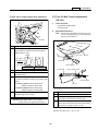
7045
NOVEMBER 2000
CSM-7045
7045
SERVICE MANUAL
NOVEMBER 2000
IMPORTANT NOTICE
Because of the possible hazards to an inexperienced
person servicing this equipment, as well as the risk of
damage to the equipment, Konica Business Technologies strongly recommends that all servicing be performed by Konica-trained service technicians only.
Changes may have been made to this equipment to
improve its performance after this service manual was
printed. Accordingly, Konica Business Technologies,
Inc., makes no representations or warranties, either
expressed or implied, that the information contained in
this service manual is complete or accurate. It is understood that the user of this manual must assume all risks
or personal injury and/or damage to the equipment while
servicing the equipment for which this service manual
is intended.
Corporate Publications Department
© 2000, KONICA BUSINESS TECHNOLOGIES, INC.
All rights reserved.
Printed in U.S.A.
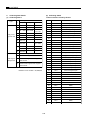
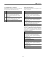
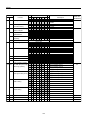
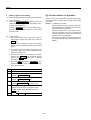
CONTENTS
CONTENTS
SAFETY AND IMPORTANT WARNING ITEMS ........... vii
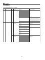
MAINBODY SECTION
IMPORTANT NOTICE ................................................... vii
DESCRIPTION ITEMS FOR DANGER, WARNING
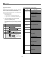
1. OUTLINE
AND CAUTION ............................................................... vii
OUTLINE OF SYSTEM ........................................ 1-A-1
7045 PRODUCT SPECIFICATIONS ................... 1-A-2
CENTER CROSS-SECTIONAL VIEW ................ 1-A-4
DRIVE SYSTEM DIAGRAM ................................. 1-B-1
[1] Main Drive ............................................ 1-B-1
[2] Drum / Toner Recycle Drive ................ 1-B-2
[3] Developing Drive .................................. 1-B-3
[4] By-pass Paper Feed / 1st Paper
Feed Drive ............................................ 1-B-4
[5] ADU Drive ............................................. 1-B-5
[6] Reversal / Paper Exit Drive ................. 1-B-6
[7] Read Unit Drive .................................... 1-B-7
[8] Toner Supply Drive .............................. 1-B-8
SAFETY WARNINGS ................................................... viii
SAFETY INFORMATION ................................................. x
IMPORTANT INFORMATION ......................................... x
SAFETY CIRCUITS ........................................................ xi
INDICATION OF WARNING ON THE MACHINE ........ xii
7045 SYSTEM CONFIGURATOR ................................ xv
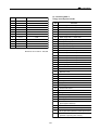
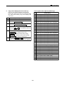
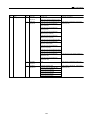
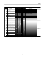
2. UNIT EXPLANATION
EXTERNAL SECTION .......................................... 2-A-1
[1] Composition .......................................... 2-A-1
DRIVE SECTION .................................................. 2-B-1
[1] Composition .......................................... 2-B-1
[2] Mechanisms ......................................... 2-B-1
[3] M1 (Main) Control ................................ 2-B-2
[4] M4 (Drum) Control ............................... 2-B-3
READ SECTION .................................................. 2-C-1
[1] Composition ......................................... 2-C-1
[2] Mechanisms ........................................ 2-C-1
[3] M2 (Scanner) Control ......................... 2-C-2
[4] Exposure Control ................................ 2-C-4
[5] Original Read Control ......................... 2-C-5
[6] APS Control ......................................... 2-C-5
[7] AE Control ........................................... 2-C-7
WRITE UNIT ........................................................ 2-D-1
[1] Composition ......................................... 2-D-1
[2] Mechanisms ........................................ 2-D-1
[3] M5 (Polygon) Control .......................... 2-D-2
[4] Image Write Control ............................ 2-D-3
DRUM UNIT .......................................................... 2-E-1
[1] Composition .......................................... 2-E-1
[2] Mechanisms ......................................... 2-E-1
[3] PCL/TSL Control .................................. 2-E-2
[4] Separation Claw Control ...................... 2-E-2
[5] Transfer Entrance Guide Plate Control .. 2-E-3
CORONA UNIT SECTION ................................... 2-F-1
[1] Composition .......................................... 2-F-1
[2] Mechanisms ......................................... 2-F-1
[3] Charging Control .................................. 2-F-2
[4] Transfer/Separation Control ................ 2-F-3
DEVELOPING UNIT ............................................ 2-G-1
[1] Composition ......................................... 2-G-1
[2] Mechanisms ........................................ 2-G-1
[3] M3 (Developing) Control ..................... 2-G-2
iii
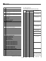
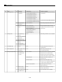
CONTENTS
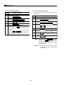
[3]
[4]
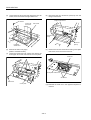
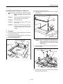
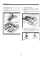
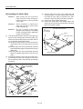
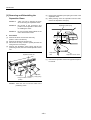
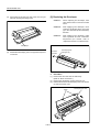
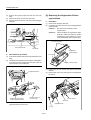
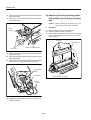
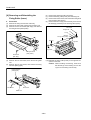
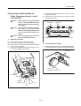
Replacing the Exposure Lamp (L1) .... 3-C-3
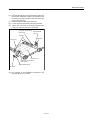
Removing and Reinstalling the
Exposure Unit ..................................... 3-C-4
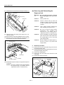
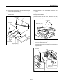
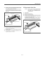
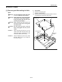
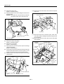
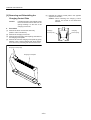
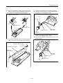
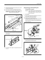
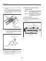
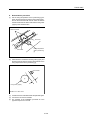
[5] Removing the Optics Wire .................. 3-C-7
[6] Installing the Optics Wire .................. 3-C-10
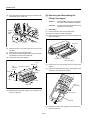
WRITE UNIT ...................................................... 3-D-1
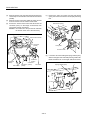
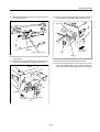
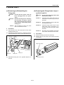
[1] Removing and Reinstalling the
Write Unit ............................................ 3-D-1
[2] Cleaning the Dust-proof Glass ........... 3-D-3
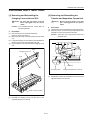
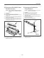
DRUM UNIT ....................................................... 3-E-1
[1] Removing and Reinstalling the
Drum Unit ........................................... 3-E-1
[2] Removing and Reinstalling
the Drum ............................................. 3-E-2
[3] Removing and Reinstalling the
Separation Claws ............................... 3-E-4
CORONA UNIT SECTION ................................. 3-F-1
[1] Removing and Reinstalling the
Charging Corona Unit and PCL ......... 3-F-1
[2] Removing and Reinstalling the
Transfer and Separation Corona Unit 3-F-1
[3] Removing and Reinstalling the
Charging the Control Plate ................. 3-F-2
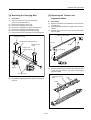
[4] Replacing the Charging Wire ............. 3-F-3
[5] Replacing the Transfer and
Separation Wires ................................ 3-F-3
[6] Replacing the Charging Wire
Cleaning Block (C) and (D) ................ 3-F-4
DEVELOPING UNIT ........................................... 3-G-1
[1] Screws That Must Not Be Removed ... 3-G-1
[2] Removing and Reinstalling the
Developing Unit .................................. 3-G-1
[3] Replacing the Developer .................... 3-G-2
TONER SUPPLY UNIT ...................................... 3-H-1
[1] Removing and Reinstalling the
Toner Cartridge .................................. 3-H-1
CLEANING/TONER RECYCLE UNIT ................. 3-I-1
[1] Removing and Reinstalling the
Cleaning Blade .................................... 3-I-1
PAPER FEED UNIT ............................................ 3-J-1
[1] Removing and Reinstalling the
By-pass Paper Feed Unit .................... 3-J-1
[2] Removing and Reinstalling the
Paper Feed Unit .................................. 3-J-1
[3] Replacing the By-pass Paper
Feed Rubber ....................................... 3-J-2
[4] Replacing the By-pass Separation
Rubber ................................................. 3-J-3
[5] Replacing the By-pass Double Feed
Prevention Rubber .............................. 3-J-3
[6] Replacing the Feed Rubber and
Paper Feed Rubber ............................. 3-J-4
[7] Removing and Reinstalling the
Double Feed Prevention Roller ........... 3-J-5
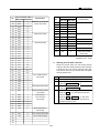
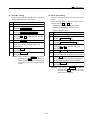
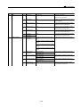
[4] Developing Bias Control ..................... 2-G-3
[5] Toner Density Control ........................ 2-G-4
[6] Dmax Control ..................................... 2-G-6
[7] Gradation Correction Control ............. 2-G-7
TONER SUPPLY UNIT ...................................... 2-H-1
[1] Composition ....................................... 2-H-1
[2] Mechanisms ....................................... 2-H-1
[3] Toner Level Detection Control ........... 2-H-3
CLEANING/TONER RECYCLE UNIT ................. 2-I-1
[1] Composition ........................................ 2-I-1
[2] Mechanisms ........................................ 2-I-1
PAPER FEED UNIT ............................................ 2-J-1
[1] Composition ........................................ 2-J-1
[2] Mechanisms ........................................ 2-J-2
[3] Paper Feed Control ............................. 2-J-3
[4] Paper Up-down Control ....................... 2-J-5
[5] Paper Size Detection Control .............. 2-J-6
[6] No Paper Detection Control ................ 2-J-7
FIXING UNIT ...................................................... 2-K-1
[1] Composition ....................................... 2-K-1
[2] Mechanisms ....................................... 2-K-1
[3] Fixing Temperature Control ............... 2-K-2
REVERSAL AND PAPER EXIT SECTION ......... 2-L-1
[1] Composition ....................................... 2-L-1
[2] Mechanisms ....................................... 2-L-1
[3] Reversal Paper Exit Control ............... 2-L-3
ADU SECTION .................................................. 2-M-1
[1] Composition ...................................... 2-M-1
[2] Mechanisms ...................................... 2-M-1
[3] Conveyance Control .......................... 2-M-3
OTHER KINDS OF CONTROL .......................... 2-N-1
[1] Parts Through Which Current Flows
When the Main Switch is
Turned OFF ........................................ 2-N-1
[2] Parts That Operate When the Power
Switch is Turned ON .......................... 2-N-2
[3] Fan Control ......................................... 2-N-4
[4] Operation Panel Control ..................... 2-N-5
[5] Counter Control .................................. 2-N-7
[6] Option Control .................................... 2-N-8
3. DISASSEMBLY/ASSEMBLY
EXTERNAL SECTION ....................................... 3-A-1
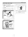
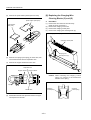
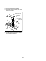
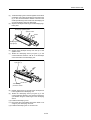
[1] Replacing the Ozone Filter ................. 3-A-1
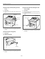
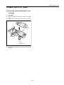
[2] Removing and Reinstalling the
Rear Cover ......................................... 3-A-2
[3] Replacing the Fixing Filter .................. 3-A-2
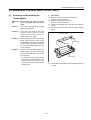
[4] Removing and Reinstalling the
Side Cover (right) ............................... 3-A-2
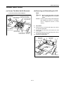
DRIVE SECTION ............................................... 3-B-1
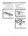
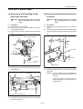
[1] Disassembly and Reassembly ........... 3-B-1
READ SECTION ................................................ 3-C-1
[1] Screws That Must Not Be Removed ... 3-C-1
[2] Removing and Reinstalling the
CCD Unit ............................................ 3-C-1
iv
CONTENTS
[8]
Removing and Reinstalling the
2nd Paper Feed Unit ........................... 3-J-5
[9] Replacing the Registration Rollers
(upper/lower) ....................................... 3-J-6
FIXING UNIT ...................................................... 3-K-1
[1] Removing and Reinstalling the
Fixing Unit .......................................... 3-K-1
[2] Replacing the Fixing Heater
Lamps 1 and 2 (L2 and L3) ................ 3-K-1
[3] Replacing the Fixing Cleaning Roller,
Fixing Roller (A) and Fixing
Cleaning Pad ...................................... 3-K-2
[4] Removing and Reinstalling the
Fixing Roller (upper) ........................... 3-K-3
[5] Removing and Reinstalling the
Fixing Claw (upper) ............................ 3-K-4
[6] Removing and Reinstalling the
Paper Exit Roller Unit (lower) ............. 3-K-5
[7] Removing and Reinstalling the
Fixing Claw (lower) ............................. 3-K-5
[8] Removing and Reinstalling the
Fixing Roller (lower) ........................... 3-K-6
[9] Removing and Reinstalling the
Fixing Temperature Sensor 1 and 2
(TH1 and TH2) ................................... 3-K-7
[10] Removing and Reinstalling the
Thermostat (TS) ................................. 3-K-8
REVERSAL AND PAPER EXIT SECTION ......... 3-L-1
[1] Removing and Reinstalling the
Reversal and Paper Exit Unit ............. 3-L-1
ADU SECTION ................................................... 3-M-1
[1] Removing and Reinstalling the ADU ... 3-M-1
SERVICE SECTION
1. ADJUSTMENT
HOW TO USE THE ADJUSTMENT SECTION ...... 1-1
[1] Construction ........................................... 1-1
ADJUSTMENTS WHEN REPLACING PARTS ...... 1-1
LIST OF ADJUSTMENT ITEMS ............................ 1-2
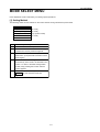
MODE SELECT MENU .......................................... 1-3
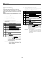
[1] Setting Method ....................................... 1-3
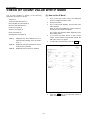
CHECK OF COUNT VALUE WITH P MODE ......... 1-4
[1] How to Use P Mode ............................... 1-4
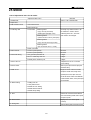
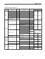
25 MODE ................................................................ 1-5
[1] Setting Method ....................................... 1-6
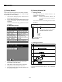
[2] Setting Software SW .............................. 1-6
[3] Paper Size Setting ................................ 1-17
[4] PM Count Setting ................................. 1-18
[5] Collecting Data ..................................... 1-19
[6] Parts Counter ....................................... 1-24
[7] Password Setting ................................. 1-28
[8] Setting Phone Number of the
Service Center ...................................... 1-29
[9] Setting the Serial Number .................... 1-30
[10] Displaying the ROM Version ................ 1-31
[11] KRDS Setting ....................................... 1-31
[12] ISW Setting ........................................... 1-31
[13] Root Counter Display ........................... 1-31
[14] Setting Date .......................................... 1-31
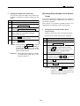
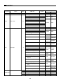
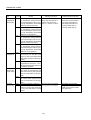
36 MODE .............................................................. 1-32
[1] Setting Method ..................................... 1-36
[2] High Voltage Adjustment ...................... 1-36
[3] Timing Adjustment ................................ 1-38
[4] Running Test Mode .............................. 1-48
[5] Test Pattern Output .............................. 1-49
[6] Density Adjustment .............................. 1-56
[7] Image Quality Adjustment .................... 1-56
[8] List Print ................................................ 1-63
[9] Adjustment of RADF ............................. 1-64
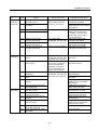
47 MODE .............................................................. 1-78
[1] 47 Mode Setting Method ...................... 1-78
[2] Initial Setting in the Field ...................... 1-79
[3] Drum Count Reset ................................ 1-79
[4] RADF Original Size Detection
Adjustment ........................................... 1-79
[5] E-RDH Memory Check ......................... 1-80
[6] RADF Sensor Adjustment .................... 1-80
[7] Input Check (code) List ........................ 1-81
[8] Output Check (code) List ...................... 1-83
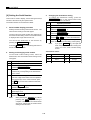
OTHER ADJUSTMENTS ..................................... 1-87
[1] Centering Adjustment ........................... 1-87
[2] Adjusting the Inclination of the
Paper Tray (DB-608) ............................ 1-88
[3] Image Distortion Adjustment ................ 1-89
v
CONTENTS
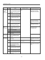
[4]
[5]
[6]
[7]
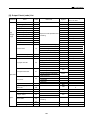
5. DIAGRAMS/TIMING CHARTS
Paper Skew Adjustment ....................... 1-90
RADF Skew Adjsutment (DF-315) ....... 1-91
RADF Paper Skew Adjustment (DF-315) ... 1-92
Tray 2/3 Belt Tension Adjustmentt (FS-109) 1-93
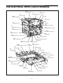
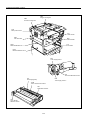
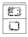
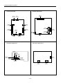
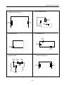
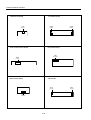
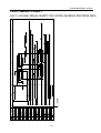
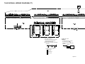
7045 ELECTRICAL PARTS LAYOUT DRAWING ... 5-1
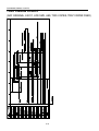
7045 CONNECTOR LAYOUT DRAWING ............. 5-4
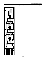
7045 TIMING CHART (8.5X11, LIFE SIZE,
MANUAL DENSITY, TWO COPIES,
DB MIDDLE TRAY PAPER FEED) ...................... 5-11
7045 TIMING CHART (ADF ORIGINAL, 8.5X11,
LIFE SIZE, AES, TWO COPIES, TRAY 1
PAPER FEED) ...................................................... 5-12
ADU TIMING CHART (8.5X11, LIFE SIZE,
THREE COPIES) ................................................. 5-13
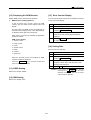
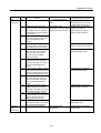
2. ISW
ISW ......................................................................... 2-1
[1] Boards that Support ISW ........................ 2-2
[2] Operating Method ................................... 2-2
3. KRDS
KRDS ..................................................................... 3-1
[1] Specifications ......................................... 3-1
[2] KRDS Setting ......................................... 3-1
[3] KRDS Set up .......................................... 3-2
[4] Calling Time Set Menu Mode (Arbitrary) .... 3-13
[5] A Point to Notice for Operation ............. 3-16
[6] ASCII Code Table ................................ 3-17
[7] Error Code Table .................................. 3-18
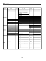
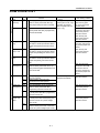
6. JAM/ERROR CODES
JAM CODE LIST .................................................... 6-1
ERROR CODE LIST .............................................. 6-5
7. APPENDIX
7045 OVERALL WIRING DIAGRAM (1/4) .. Appendix-1
7045 OVERALL WIRING DIAGRAM (2/4) .. Appendix-2
7045 OVERALL WIRING DIAGRAM (3/4) .. Appendix-3
7045 OVERALL WIRING DIAGRAM (4/4) .. Appendix-4
4. SERVICE
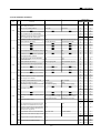
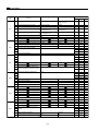
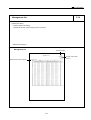
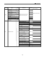
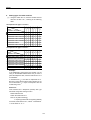
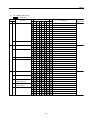
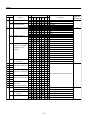
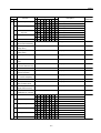
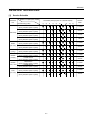
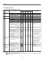
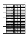
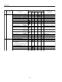
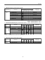
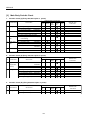
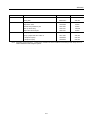
SERVICE SCHEDULE ........................................... 4-1
[1] Service Schedule ................................... 4-1
[2] Maintenance Items ................................. 4-2
[3] Main Body Periodic Check ..................... 4-6
[4] RADF [DF-315] ....................................... 4-7
[5] DB [DB-208] ........................................... 4-7
[6] DB [DB-608] ........................................... 4-7
[7] FNS [FS-109] ......................................... 4-7
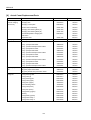
[8] Actual Count Replacement Parts ........... 4-8
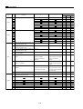
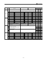
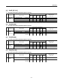
COPY MATERIALS .............................................. 4-10
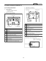
[1] PM Parts Kit Composition .................... 4-10
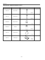
SERVICE MATERIALS LIST ................................ 4-12
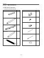
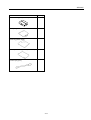
SPECIAL TOOLS LIST ........................................ 4-13
vi
SAFETY AND IMPORTANT WARNING ITEMS
SAFETY AND IMPORTANT WARNING ITEMS
Read carefully the Safety and Important Warning Items described below to understand them before
doing service work.
IMPORTANT NOTICE
Because of possible hazards to an inexperienced person servicing this copier, as well as the risk of
damage to the copier, Konica Corporation, strongly recommends that all servicing be performed only
by Konica-trained service technicians.
Changes may have been made to this copier to improve its performance after this Service Handbook
was printed. Accordingly, Konica Corporation, makes no representations or warranties, either expressed or implied, that the information contained in this Service Handbook is complete or accurate.
It is understood that the user of this Service Handbook must assume all risks or personal injury and/
or damage to the copier while servicing the copier for which this Service Handbook is intended.
Therefore, this Service Handbook must be read carefully before doing service work both in the
course of the technical training and even after that, for keeping the correct maintenance and control
of the copier. Keep this Service Handbook also for the future service. When it is impossible to read
the description about safety and warning (due to contamination or tear), the relevant page should be
replaced.
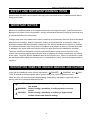
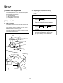
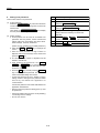
DESCRIPTION ITEMS FOR DANGER, WARNING AND CAUTION
In this Service Handbook, each of three expressions, “ DANGER”, “ WARNING” and “ CAUTION” is defined as follows together with a symbol mark to be used in a limited meaning.
When servicing, the relevant works (disassembling, assembling, adjustment, repair and maintenance) need to be conducted with utmost care.
DANGER:
WARNING:
CAUTION:
Actions having a high possibility of suffering death or serious wound
Actions having a possibility of suffering death or serious
wound
Actions having a possibility of suffering a slight wound,
medium trouble and material damage
vii
SAFETY AND IMPORTANT WARNING ITEMS
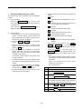
SAFETY WARNINGS
1. Advance Preparation for Safety Checks
[1] Modifications Not Authorized by
Konica
CAUTION:
(1) Wear clothing that facilitates work and is designed
for safety.
(2) Carry out all procedures carefully to prevent injury.
(3) Be sure to disconnect the power cord of the copier
and all optional equipment from the AC outlet.
Simply turning off the power switch is not sufficient,
because paper feed units or other electrical equipment may be powered also when the power switch
is turned off.
(4) Proceed with special care when performing operation checks or adjustment while the unit is powered.
When carrying out operation checks or adjustment
while external covers are removed, the risk of electrical shock exists when touching parts which carry
high voltage or electrical charge. The risk of injury
exists when touching moving parts such as gears or
chains.
Konica copiers are renowned for their high reliability. This
reliability is achieved through high-quality design and a solid
service network.
Photocopier design is a highly complicated and delicate
process where numerous mechanical, physical, and electrical aspects have to be taken into consideration, with the aim
of arriving at proper tolerances and safety factors. For this
reason, unauthorized modifications involve a high risk of
degrading performance and safety. Such modifications are
therefore strictly prohibited. The points listed below are not
exhaustive, but they illustrate the reasoning behind this
policy.
PROHIBITED ACTIONS :
(1) Using extension cables or a different power cord
than specified by Konica.
(2) Using other fuses than specified by Konica. Safety
will not be assured, leading to a risk of fire and
injury.
(3) Disabling fuses or bridging fuse terminals with wire,
metal clips, solder or similar. (This applies also to
thermal fuses.)
(4) Removing air filters (except for replacement).
(5) Disabling relay functions (such as wedging paper
between relay contacts, etc.).
(6) Disabling safety functions (interlocks, safety circuits, etc.). Safety will not be assured, leading to a
risk of fire and injury.
(7) Performing actions to copier not described in the
instruction manual or the service handbook.
(8) Using parts other than specified by Konica.
2. Safety Checkpoints
The following list is not exhaustive, but it includes actions
which must be carried out at every on-site service.
CAUTION:
(1) Check external covers and the frame for sharp
edges, burrs, or nicks.
(2) Check external covers and hinges for loosening or
damage.
(3) Check wiring for squeezing or damage.
(4) Check power cord for insulation problems (conductor must not be exposed).
(5) Check power cord and cable ties etc. for loosening
from frame.
WARNING:
(1) Verify that the copier is properly grounded. If a
problem is detected, establish a proper ground
connection.
(2) Connecting the ground lead to an improper point
such as listed below results in a risk of explosion
and electric shock.
Unsuitable ground points:
- Gas pipe
- Lightning rod
- Telephone line ground
- Plastic water pipe or water pipe or faucet that has
not been approved by authorities for grounding
use
[2] Checkpoints When Performing On-site
Service
Konica copiers are extensively tested before shipping, to
ensure that all applicable safety standards are met, in order
to protect the customer and customer engineer from the risk
of injury. However, in daily use, any electrical equipment may
be subject to parts wear and eventual failure. In order to
maintain safety and reliability, the customer engineer must
perform regular safety checks.
viii
SAFETY AND IMPORTANT WARNING ITEMS
[3] Handling of Materials for Servicing
3. Description of Safety Checks
(1)
(2)
(3)
(4)
(5)
(6)
(7)
(8)
CAUTION:
Before performing safety check work, read all relevant documentation (service handbook, technical
notices, etc.) and proceed according to the prescribed procedure, using only the prescribed tools.
Do not carry out any adjustments not described in
the documentation.
If the power cord is damaged, replace it only with the
specified power cord. If the power cord insulation
has been damaged and there are exposed sections,
short- circuits and overheating may occur, leading to
a serious fire risk.
Do not route the power cord so that it can be stepped
on or pinched. Otherwise overheating may occur,
leading to a serious fire risk.
When disconnecting any cables, always grasp the
connector and not the cable (especially in the case of
AC and high-voltage leads).
Carefully remove all toner remnants from electrical
parts, electrodes, etc.
Make sure that wiring cannot come into contact with
sharp edges, burrs, or other pointed parts.
Double-check to make sure that all screws, components, wiring, connectors, etc. that were removed for
safety check maintenance have been reinstalled in
the original location. (Pay special attention to forgotten connectors, pinched cables, forgotten screws,
etc.)
When installation and preventive maintenance, verify
that the power cord has been securely plugged into
the AC outlet. Contact problems may lead to increased resistance, overheating, and the risk of fire.
(1)
(2)
(3)
(4)
CAUTION: Drum cleaner (alcohol-based) and roller
cleaner (acetone- based) are highly flammable and must be handled with care.
When using these materials for cleaning of copier parts, observe the following precautions.
Disconnect the power cord from the AC outlet.
Use only a small amount of cleaner at a time and take
care not to spill any liquid. If this happens, immediately wipe it off.
Perform cleaning only in an environment where
sufficient ventilation is assured. Breathing large
quantities of organic solvents can lead to discomfort.
Do not replace the cover or turn the unit on before
any solvent remnants on the cleaned parts have
fully evaporated.
CAUTION: Toner and developer are not harmful
substances, but care must be taken not
to breathe excessive amounts or let the
substances come into contact with eyes
etc. It may be stimulative. If the substances get in the eye, rinse it with
plenty of water immediately. When
symptoms are noticeable, consult a
physician.
[4] Measures to Take in Case of an
Accident
(1) If an accident has occurred, the distributor who has been
notified first must immediately take emergency measures to provide relief to affected persons and to prevent
further damage.
(2) If a report of a serious accident has been received from
a customer, an on-site evaluation must be carried out
quickly and Konica Corporation must be notified.
(3) To determine the cause of the accident, conditions and
materials must be recorded through direct on-site checks,
in accordance with instructions issued by Konica Corporation.
(4) For reports and measures concerning accidents, consult your superior, and follow the regulations set in
"Standards for the Control Program for Measures Against
Electrical Equipment Accidents".
WARNING:
(1) Before disassembling or adjusting the write unit or
any parts that use a laser, make sure that the power
cord has been disconnected.
(2) Do not remove the main cover of the write unit. Direct
exposure of the eye to laser beams may lead to
blindness.
(3) Do not turn the copier on while the write unit is not
installed in its normal position.
(4) Danger of explosion if battery is incorrectly replaced,
replace only with the same or equivalent recommended by the manufacturer. Discard used batteries according to the manufacture's instructions.
[5] Conclusion
(1) Safety of users and customer engineers depends highly
on accurate maintenance and administration. Therefore, safety can be maintained by the appropriate by the
proper daily service work conducted by the customer
engineer.
(2) When performing service, each copier on the site must
be tested for safety. The customer engineer must verify
the safety of parts and ensure appropriate management
of the equipment.
VORSICHT:
Expiosionsgefahr dei unsachegemäßem Austausch
der Battetie. Ersatz nur durch denselben oder einen
vom. Hersteller empfohlenen gleichwertigen Typ.
Entsorgung gebrauchter Batterien nach Angaben
des Herstellers.
ix
SAFETY AND IMPORTANT WARNING ITEMS
SAFETY INFORMATION
IMPORTANT INFORMATION
The Center for Devices and Radiological Health (CDRH) of the U.S. Food and Drug Administration
implemented regulations for laser products manufactured since August 1, 1976. Compliance is mandatory for products marketed in the United States.
This copier is certified as a "Class 1" laser product under the U.S.
Department of Health and Human Services (DHHS) Radiation Performance Standard according to
the Radiation Control for Health and Safety Act of 1968. Since radiation emitted inside this copier is
completely confined within protective housings and external covers, the laser beam cannot escape
during any phase of normal user operation.
x
SAFETY AND IMPORTANT WARNING ITEMS
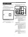
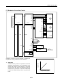
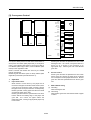
SAFETY CIRCUITS
[2] L2/L3 (fixer heater lamps) overheat
protection circuit
This unit incorporates the following electrical safety circuits
to guard against the risk of accidents in case of any
malfunction.
[1] Overall protection circuit
[2] L2/L3 (fixer heater lamps) overheat protection circuit
Operation principles of these safety circuits are described
below. It is necessary to understand this information fully, in
order to prevent mistakes during servicing.
CB
DCPS1
RL1
TS
PRDB
RL1
TH1
TH2
[1] Overall protection circuit
L2
Control
section
AC driver
section
L3
LBR
1. Software protection
The output voltage of TH1 (fixer temperature sensor 1) is
constantly read by the CPU. If the voltage becomes
abnormal, L2 (fixer heater lamp 1), L3 (fixer heater lamp
2), and RL1 (main relay) are set to OFF.
CAUTION: The clearance between the roller and
TH1 may not be altered.
After replacement, verify that dimensions
correspond to specifications.
RL1 may not be disabled under any circumstances.
1. LBR (line breaker) protection
When an excessively large current flows due to a shortcircuit in the AC line, the AC line itself is instantly cut off
due to the action of this circuit breaker.
CAUTION: The line breaker must not be disabled
under any circumstances.
2. Hardware protection
The output voltages of TH1 and TH2 (fixer temperature
sensors) are compared to a reference voltage in the
comparator circuit. If the voltage exceeds the threshold,
L2, L3, and RL1 are set to OFF in hardware.
CAUTION: Periodically check the roller contact area
of TH2 and replace the sensor if any
problem is detected.
Since the TH1 is non-contact, check the
distance from the roller and installing
orientation of the sensor when an abnormality has occurred.
RL1 may not be disabled under any circumstances.
3. TS (thermostat) protection
If the fixer roller temperature exceeds the threshold, TS
goes OFF and directly cuts power to L2 and L3.
CAUTION: TS may not be replaced by any other
conductor.
Do not change the distance between the
TS and roller.
xi
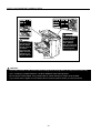
SAFETY AND IMPORTANT WARNING ITEMS
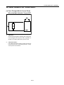
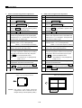
INDICATION OF WARNING ON THE MACHINE
The caution labels are attached to the machine areas, as shown below, where you are advised
to pay special attention to avoid any dangerous situations or serious injury.
CAUTION
PRECAUCION
ATTENTION
ATTENZIONE
VORSICHT
CAUTION
PRECAUCION
ATTENTION
ATTENZIONE
CAUTION
DO NOT INSERT
your finger into the
two RADF hinge
portions, otherwise
you may be injured.
VORSICHT
WARNING
This area generates
high voltage. If
touched, electrical
shock may occur. DO
NOT TOUCH!
CAUTION
High temperature!
Do not touch.
Use care when
clearing paper.
ATTENTION
Température élevée!
Risque de brûlure.
Soyez prudent en
retirant la feuille
coincée.
VORSICHT
PRECAUCION
ATTENZIONE
Heiße Oberfläche! ¡Temperatura alta! Alta temperatura!
Brandverletzungsgefahr. No tocar. Tener
Non toccare. Agire
Bei Beseitigung von
con prudenza nel
Papierstaus vorsichtig cuidado al
remover el papel. rimuovere la carta.
vorgehen.
CAUTION
This internal area is
very hot. To avoid
getting burned DO
NOT TOUCH.
CAUTION:
If you carry out work on the machine without reading these warning labels, an unexpected accident may
occur, resulting in possible blindness. DO NOT REMOVE these warning labels.
Do not remove caution labels. If any caution label or caution indicator is soiled, clean the label.
If you cannot make it legible or if the caution label is removed, please contact your Service Centre.
xii
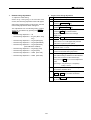
SAFETY AND IMPORTANT WARNING ITEMS
<Read section>
WARNING
Unplug the machine before removing platen glass.
DANGER
Débrancher le copieur abant de retirer la vitre d’exposition.
WARNUNG
Vor Entfernen des Vorlagenglases Netzstecker ziehen.
ADVERTENCIA Desenchufe la máquina antes de quitar el vidrio.
AVVERTIMENTO Estrarre la spina dalla presa prima di rimuovere il vetro di esposizione.
<Write unit>
CAUTION:
You may be burned or injured if you touch any area that you are advised by any caution label to keep
yourself away from.
Do not remove caution labels. If any caution label or caution indicator is soiled, clean the label.
If you cannot make it legible or if the caution label is removed, please contact your Service Centre.
xiii
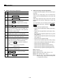
SAFETY AND IMPORTANT WARNING ITEMS
CAUTION:
To avoid injury
when the Finisher
middle exit tray
moves up and
down, DO NOT
PUT your hand into
the two portions of
the closing area.
CAUTION:
DO NOT INSERT
your finger into
the two staple
driving portions
or into the
grooves of the
paper exit lever,
otherwise you
may be injured.
FS-109 Finisher
CAUTION:
If you carry out work on the machine without reading these warning labels, an unexpected accident may
occur, resulting in possible blindness. DO NOT REMOVE these warning labels.
Do not remove caution labels. If any caution label or caution indicator is soiled, clean the label.
If you cannot make it legible or if the caution label is removed, please contact your Service Centre.
xiv
SAFETY AND IMPORTANT WARNING ITEMS
xv
7045
MAINBODY
SECTION
1
OUTLINE
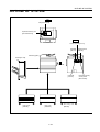
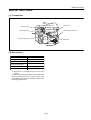
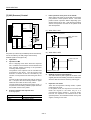
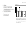
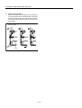
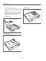
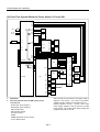
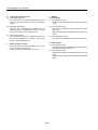
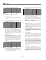
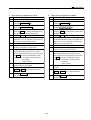
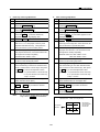
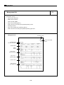
OUTLINE OF SYSTEM
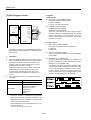
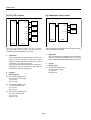
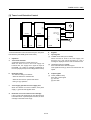
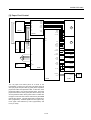
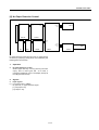
OUTLINE OF SYSTEM
Top
CB(Control board)
Expansion memory unit
[MU-403/404/405]
Back
Printer controller [IP-431]
Hard disk
[HD-103]
Network board
[KN-303]
Main body [7045]
Finisher [FS-109]
Key counter
PostScript
[PS-342]
PFU 3 trays
[DB-208]
PFU 1 tray
[DB-208A]
1-A-1
PFU 1 tray + LCT
[DB-608]
Expansion memory
unit for printer
[MU-403/404]
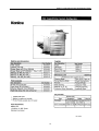
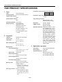
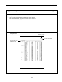
7045 PRODUCT SPECIFICATIONS
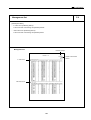
7045 PRODUCT SPECIFICATIONS
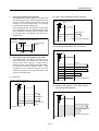
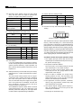
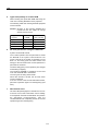
Continuous copy speed (life size copies/min):
1. Type
Type:
Semi-console type
Copying method:
Indirect electrostatic method
manual (9 steps), AES
Arbitrary density (2 modes)
OPC
Sensitizing method: Laser writing
One stacked tray
(500 sheets; 21 lb)
LCT (1500 sheets; 21 lb)*1
*1: Option
2. Functions
Sheets; book; solid object
Original size:
A3 max.
Copy sizes:
11 x 17, 8.5 x 14,
8.5 x 11, 5.5 x 8.5
600 dpi x 600 dpi
E-RDH memory:
Standard 32 MB
Application functions: Sheet/Cover Insertion, Chapter, Combination (2-in-1, 4-in-1,
8-in-1), Booklet, Special paper,
Image Insert, Dual page, Special Original, Text/Photo Enhance (text/photo/Increase),
Reverse Image, Repeat,
Frame/Fold Erasure, Auto Layout, Image Shift, Non-image
Area Erase, memory function,
density monitor, single step
copy, density shift, printing
function, copy reservation, original rotation, weekly timer, job
memory, KRDS
PFU (500 sheets/tray, 21 lb
x 1 tray, or 3 trays)*1
Originals:
Resolution:
Maximum 288 MB
Multisheet by-pass tray
(100 sheets; 21 lb)
ADU usable paper size:
11 x 17, 8.5 x 14,
8.5 x 11, 8.5 x 11R,
3. Applicable copy paper
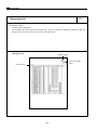
Magnification:
Fixed magnifications:
x0.50, x0.65, x0.77, x1.00,
x1.29, x1.55, x2.00
Plain paper:
16 to 24 lb high-quality paper
Special paper:
Label paper
(by-pass feed only) OHP film
Blueprint-master paper
Three kinds.
13 to 16 lb high-quality paper
Zoom magnifications:
24 to 35 lb high-quality paper
x0.25 to x4.00 (1% steps)
Vertical magnifications:
x0.25 to x4.00 (1% steps)
Horizontal magnifications:
x0.25 to x4.00 (1% steps)
Within 90 seconds (at 20½C,
at rated voltage)*1
*1 Warm-up time differs depending on the Power
Source (Voltage).
First copy out time: Approx. 3.9 seconds
*
45
Copy density selections:
Photosensitive material:
Warm-up time:
8.5x11
1 to 999
Fixed
Special ratio:
CPM
Continuous copy count:
Original table method:
Paper feed trays:
Size
When using face-up paper
exit, manual mode, platen
mode and tray 1 are in
use.
1-A-2
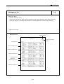
7045 PRODUCT SPECIFICATIONS
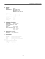
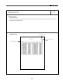
4. Options
Finisher:
FS-109
Drawer base unit:
DB-208 (500 x 3 trays)
DB-208A (500 x 1 tray)
DB-608 (500 X 1 tray + 1500 LCT)
Key counter
Expansion memory unit: MU-403 (32MB DIMM)
MU-404 (64MB DIMM)
MU-405 (128MB DIMM)
Printer controller:
IP-431
Hard disk:
HD-103
Network board:
KN-303
PostScript:
PS-342
5. Particulars of machine
Power supply:
120 VAC ±10.0%
Power consumption: Max. 1500W
(Full option)
Weight:
Approx. 229 lbs.
Machine dimensions: Width:
25.5 in.
Depth: 27.75 in.
Height: 29.3 in.
6. Maintenance and Life
Maintenance:
Every 100,000 copies
7. Consumables
Developer:
Common with Konica 7033/7040
Toner:
Common with Konica 7040
Drum:
Common with Konica 7033/7040 (φ60)
8. Environmental conditions
Temperature:
50°C to 86°C
Humidity:
10% to 80%RH
Note: Specifications are subject to change without notice.
1-A-3
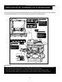
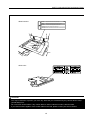
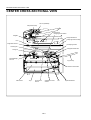
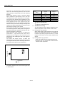
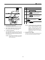
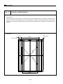
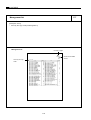
CENTER CROSS-SECTIONAL VIEW
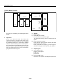
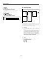
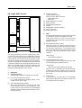
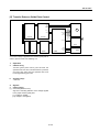
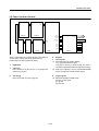
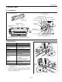
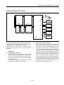
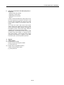
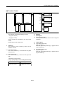
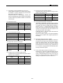
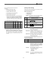
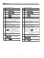
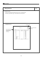
CENTER CROSS-SECTIONAL VIEW
DF-315 (standard)
CB (control board)
Exposure lamp
Charging corona section
Slit glass
Image read section
PCL
Image write section
Original
image read
position
ICB (image control board)
Developing section
Cleaning unit
2nd paper feed section
Fixing unit
Reversal/Paper
exit unit
By-pass tray
Transfer corona section
ADU section
Tray 1
Conveyance
section
Separation corona
section
1-A-4
TSL
Paper feed section
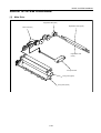
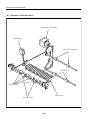
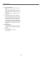
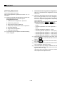
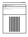
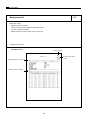
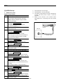
DRIVE SYSTEM DIAGRAM
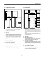
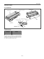
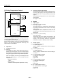
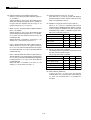
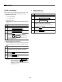
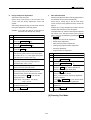
DRIVE SYSTEM DIAGRAM
[1]
Main Drive
Registration MC (MC1)
Registration roller (upper)
Main motor (M1)
Registration roller
(lower)
Conveyance belt
Fixing roller (upper)
Fixing roller (lower)
1-B-1
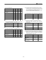
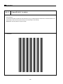
DRIVE SYSTEM DIAGRAM
[2]
Drum / Toner Recycle Drive
Drum
Drum motor (M4)
Separation claw swing gear
Toner conveyance screw
Toner recycle screw
1-B-2
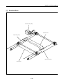
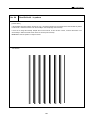
DRIVE SYSTEM DIAGRAM
[3]
Developing Drive
Developing motor (M3)
Developing MC
(MC2)
Developing drive input gear (1)
Agitator screw
Developing drive
input gear (2)
Developing sleeve
Agitator wheel
1-B-3
DRIVE SYSTEM DIAGRAM
[4]
By-pass Paper Feed / 1st Paper Feed Drive
By-pass paper feed roller
A
1st paper feed motor (M6)
By-pass double feed
prevention roller
By-pass SD (SD4)
By-pass separation roller
A
Paper feed pulley
Paper feed pulley
Registration paper feed
roller
Tray motor (M8)
Paper conveyance pulleys
Separation roller
Paper feed roller
1-B-4
Double feed prevention roller
DRIVE SYSTEM DIAGRAM
[5]
ADU Drive
Registration roller (upper)
Conveyance roller (C)
Conveyance roller (B)
Registration
roller (lower)
ADU paper feed
motor (M501)
ADU restart
MC (MC501)
ADU loop MC (MC502)
Conveyance roller (A)
ADU feed MC (MC503)
1-B-5
DRIVE SYSTEM DIAGRAM
[6]
Reversal / Paper Exit Drive
Reversal/paper exit motor (M12)
Gate SD (SD5)
Paper exit reversal rollers
Reversal rollers
Paper exit rollers
Switching guide
Conveyance rollers
1-B-6
DRIVE SYSTEM DIAGRAM
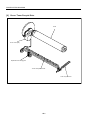
[7]
Read Unit Drive
Scanner motor (M2)
Exposure unit
Optics wire (rear)
Optics wire (front)
V-mirror unit
1-B-7
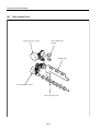
DRIVE SYSTEM DIAGRAM
[8]
Toner Supply Drive
Toner supply motor 1 (M10)
Toner cartridge drive
coupling
Agitator plate
Toner supply motor 2 (M11)
Toner conveyance screw
1-B-8
2
UNIT EXPLANATION
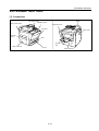
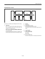
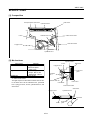
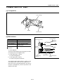
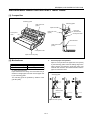
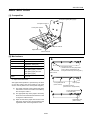
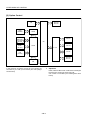
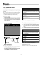
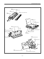
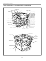
EXTERNAL SECTION
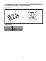
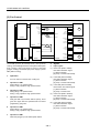
EXTERNAL SECTION
[1] Composition
Sub power swicth
Main power switch
RADF
Operation panel
Right side cover
Front door
Rear cover
Left side
cover
ADU
By-pass
tray
Paper exit cover
Tray 1
Paper feed door
2-A-1
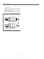
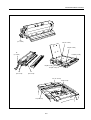
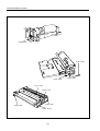
DRIVE SECTION
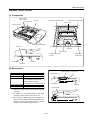
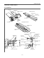
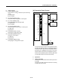
DRIVE SECTION
[1] Composition
Drum motor
Scanner motor
Reversal paper exit motor
Developing motor
1st paper feed motor
Main motor
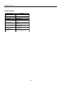
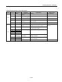
[2] Mechanisms
Mechanisms
Drum drive *1
Developing drive *1
1st paper feed drive
2nd paper feed, conveyance and fixing drive
ADU drive
Reversal/paper exit drive
Methods
Gear drive
Gear drive
Timing belt + gear drive
Gear drive
Timing belt + gear drive
Timing belt + gear drive
*1: Separation of the different parts of the drive
system
The drum and developing agitator of this machine are
driven by separate motors in order to improve the
serviceability of the drum unit and also to improve the
developing performance.
2-B-1
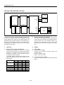
DRIVE SECTION
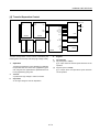
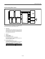
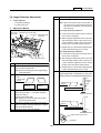
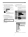
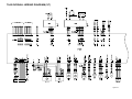
[3] M1 (Main) Control
5VDC
28VDC
SGND
PGND
24VDC
PGND
PGND
DCPS2
DCPS1
M1
5VDC
5VDC
SGND
CONT
LOCK SIG
SGND
M1 CLK
CB
ICB
SCDB
SGND
PRDB
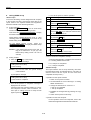
2.
M1 (main) is controlled by the PRDB (printer drive
board).
1.
PS16 SIG
PS16
5VDC
Signals
a. Input signals
(1) LOCK SIG (M1 to PRDB)
M1 rotational status detection signal
This signal becomes [L] when M1 reaches the set
speed.
Operation
M1 is a 24 V drive DC motor which drives the
conveyance section, 2nd paper feed section, fixing
section and conveyance belt. M1 is PLL-controlled
by feedback signals from a speed sensor installed
inside M1 itself, maintaining it at a constant speed.
M1 goes ON after the specified time from when the
Start print button is pressed, and goes OFF again
after the specified time from PS16 (registration)
going OFF at the final copy exit.
(2) PS16 SIG (PS16 to PRDB)
Paper detection signal used for detecting the paper
feed temporary stop position.
PS16 goes ON and outputs [H] when paper is
detected at the paper feed temporary stop position.
b. Output signals
(1) CONT (PRDB to M1)
M1 drive control signal
[L]: M1 ON
[H]: M1 OFF
(2) M1 CLK (PRDB to M1)
Reference clock signal for controlling the speed of M1
2-B-2
DRIVE SECTION
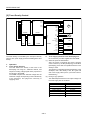
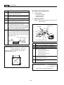
[4] M4 (Drum) Control
5VDC
28VDC
24VDC
SGND
PGND
PGND
DCPS2
DCPS1
M4
5VDC
5VDC
SGND
CONT
LOCK SIG
SGND
M4 CLK
CB
ICB
PRDB
SCDB
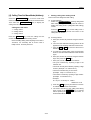
2.
M4 (drum) is controlled by the PRDB (printer drive board).
1.
Signals
a. Input signal
(1) LOCK SIG (M4 to PRDB)
M4 rotational status detection signal
This signal becomes [L] when M4 reaches the set
speed.
Operation
M4 is a 24 V drive DC motor which drives the drum,
toner conveyance screw, toner recycle screw and
separation claw swing section.
M4 is PLL-controlled by feedback signal from a
speed sensor installed inside M4 itself, maintaining it
at a constant speed.
M4 goes ON when the Start button is pressed, and
goes OFF again when the final copy has been exited.
b. Output signals
(1) CONT (PRDB to M4)
M4 drive control signal
[L]: M4 ON
[H]: M4 OFF
(2) M4 CLK (PRDB to M4)
Reference clock signal for controlling the speed of M4
2-B-3
READ SECTION
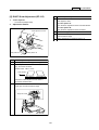
READ SECTION
[1] Composition
APS 1 sensor
APS 2 sensor
Exposure unit
Optics driven sheet (lower)
CCD unit
Optics driven sheet (lower)
V-mirror unit
Optics rail (rear)
Optics rail (front)
2nd mirror
CCD unit
Exposure unit
Optics driven sheet
(upper)
Optics driven
sheet (upper)
1st mirror
V-mirror unit
3rd mirror
[2] Mechanisms
Platen original
Mechanisms
Light source
Exposure
Scanning *1
Methods
Xenon lamp
Slit exposure
Platen original scanning:
1st, 2nd and 3rd mirror shift
RADF original scanning:
Fixed light source / Original moving
Lamp power supply Lamp cord
Cooling of optics
Cooling of intake air using a fan
Exposure unit
Original glass (1)
V-mirror unit
RADF original
*1: Platen original scanning and RADF original
scanning
a. An original on the original glass is read while
moving the exposure unit and V mirror unit.
b. When reading a RADF original, the exposure unit
and V mirror unit shift to under the original glass (1).
Original reading takes place with the original
passing over the stationary exposure unit.
2-C-1
CCD unit
READ SECTION
c.
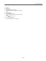
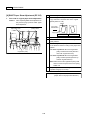
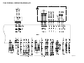
[3] M2 (Scanner) Control
5VDC
28VDC
5VDC
PGND
SGND
SGND
DCPS1
PGND
PGND
24VDC
24VDC
28VDC
PGND
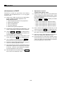
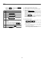
Initial operation when power is turned ON
When SW2 (sub power) is turned ON, the exposure
unit performs a home position search. The home
position search operation differs depending upon
whether PS3 is ON or OFF. After the home position
search, the exposure unit waits in the platen mode
APS read position.
(1) When PS3 is ON
Shading correction read position
DCPS2
24VDC
A
A
B
B
24VDC
Platen APS read
position
M2
SGND
OPT HOME
CB
ICB
SCDB
PS3
5VDC
Reference point
PS3
(2) When PS3 is OFF
M2 (scanner) is driven by the SCDB (scanner drive board),
and is controlled by the ICB (image control board).
Related signal is PS3 (optics HP).
Platen APS read
position
1.
Operation
a.
Operation of M2
M2 is a stepping motor which drives the exposure
unit. It rotates in the forward or reverse direction and
also changes speed according to the particular
scanning control operation.
The position of the exposure unit is controlled and
monitored by PS3 alone. The drive period and
direction of rotation of M2 are controlled by the
number of count pulses from when PS3 goes ON or
OFF.
The ICB continuously monitor the state of motion of
M2. It acquires the control timing related to paper
feed from the number of drive count pulses.
The ICB continuously monitors the motion of M2. It
acquires the control timing related to paper feed from
the number of drive count pulses.
b.
Shading correction read position
Reference point PS3
Scanning speed of the exposure unit
Scanning speed
Magnification
Forward
Return
Scanning speed
210 mm/sec (1:1)
862 mm/sec (Max.)
2-C-2
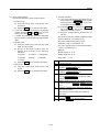
d.
Shading correction read operation
The white reference plate is glued at the back of the
original glass and the shading correction is carried out
when the SW2 is turned on and every scanning job.
e.
Exposure scan mode
There are two exposure scanning modes, a platen
mode and a DF mode.
In the platen mode, the exposure unit scans and
reads the original in the same way as in a
conventional copying machine. In the DF mode,
however, the exposure unit remains fixed in the
specified position, and instead the RADF conveys the
original, causing it to be read.
READ SECTION
f.
Scanning operation during DF mode
The read position in the DF mode is on the paper exit
side of PS3 (optics HP). While the exposure unit is
moving from the standby position (platen APS read
position) to the DF read position, the shading
correction read operation takes place.
Upon reaching the DF read position, the exposure
unit remains there until the original has been read,
upon completion of reading, then once again moves
to the platen APS read position and goes into a
standby status.
DF original
read position
(2) When manual density has been selected
Shading correction read position
PS3
Exposure scan
Platen APS read position
Shading correction read position
Reference point
Platen APS read
position
(3) Booklet mode (Output 1 to N, AE mode)
Reference
point
g.
Shading correction read position
PS3
PS3
Scanning operation during platen copy mode
In the platen mode, the motion of the exposure unit
differs depending upon whether the copy density
mode is set to AE or Manual. In both cases, a
shading correction read operation takes place before
the exposure scanning operation starts. After
completion of the exposure scanning, then the
exposure unit moves to the APS read position and
goes into a standby status.
AE scan
Exposure scan (rear half)
Exposure scan (front half)
(1) AE mode
Platen APS read position
Reference point
Shading correction read position
PS3
(4) Booklet mode (Output 1 to N, When manual
density has been selected)
Shading correction read position
PS3
AE scan
Exposure scan
Platen APS read
position
Exposure scan (rear half)
Reference point
Exposure scan (front half)
Platen APS read position
Reference point
2-C-3
READ SECTION
2.
Signals
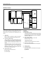
[4] Exposure Control
a. Input signal
(1) OPT HOME (PS3 to SCDB to ICB)
Exposure unit home position detection signal
[L]: Exposure unit is in the home position.
[H]: Exposure unit is not in the home position.
28VDC
PGND
24VDC
24VDC
PGND
PGND
b. Output signal
(1) A, A, B, B (SCDB to M2)
M2 (scanner) ON/OFF drive signal
PGND
LV
LAMP ON/OFF
HV
L1
24VDC
DCPS1
L1 INVB
L1 CONT
24V
0V
ICB
SCDB
Power is supplied to L1 (exposure lamp) from the L1 INVB
(L1 inverter) and is controlled by the ICB (image control
board) via the SCDB (scanner drive board).
1.
Operation
L1 is a xenon lamp which is driven by an inverter
circuit.
A xenon lamp provides a stable light intensity and
also generates relatively little heat, hence it does not
require a light intensity control circuit that is used in
conventional copying machines, and also protective
control that is normally required due to heat
generation from the lamp is no longer used.
2.
Signals
a. Output signal
(1) LAMP ON/OFF (ICB to SCDB to L1 INVB)
L1 ON/OFF control signal
[L]: L1 ON
[H]: L1 OFF
2-C-4
READ SECTION
[5] Original Read Control
5VDC
28VDC
SGND
PGND
[6] APS Control
5VDC
28VDC
SGND
PGND
12VDC
SGND
12VDC
CB
SGND
DCPS2
DCPS1
ADB
DCPS2
DCPS1
PS3
GND
SD0
SD1
SGND
PS25
OPT HOME
PS26
5VDC
PS3
PS4
/SEN
APS BOOK
5VDC
APS TIMING
PS4
SGND
CCD
SGND
APS DATA2
PS25
5VDC
RCK
GND
SGND
TCK
CB
ICB
GND
APS DATA3
ADB
ICB
The original is read by the CCD sensor installed on
the ADB (A/D converter board).
1.
SCDB
APS takes place as a result of the signals read by the
APS sensors and CCD sensor being sent to the ICB
(image control board) when the RADF is opened and
closed.
Operation
Related signals are PS3, PS4 (APS timing) and PS301
(DF open/close detect).
The light from the exposure lamp reflects back from
the original, passes through a lens, and hits the CCD
sensor. The CCD sensor generates an anolog
electrical signal corresponding to the light intensity.
The ADB then converts this signal into a digital
signal.
a.
PS26
5VDC
Original read operation
The original read timing is as follows.
1.
Operation
a.
APS detection operation
The APS detection operation differs depending upon
whether the platen mode or DF mode is used.
(1) During a DF copy operation
An original size is detected by ON or OFF of PS302
(original size detect 1) and PS303 (original size detect
2) on the paper feed tray of RADF, and resistance
value of VR301 (original size detect).
(1) During a platen copy operation
PS3 (optics HP) goes OFF after the specified time
from when the Start button is pressed, and then the
exposure unit moves 2 mm to the paper feed side.
(2) During a platen copy operation
APS detection is used to detect the original size. This
is done by combining the ON/OFF signals from PS25
(APS 1) and PS26 (APS 2) with the detection signal
from the CCD sensor mounted on ADB.
(2) During a DF copy operation
After the specified time from the ON of PS308
(original feed detect) by original leading edge.
2-C-5
READ SECTION
PS25 (APS 1) and PS26 (APS 2) detect the original
size in the sub-scanning direction, and the CCD
sensor detects the original size in the main scanning
direction.
During APS detection, when L1 (exposure lamp)
lights, gradations of light intensity occur in the main
scanning direction due to the presence of an original.
The CCD sensor detects these gradations of light
intensity along one line, and the ICB (image control
board) judges the size of the original in the main
scanning direction from the positional relationship
between the two points where the light intensity level
switches from black generated by a sky shot to white
generated by the edge of the original.
Close RADF, then detection of the original size in the
main scanning direction takes place once again at
the instant PS301 (DF open/close detect) goes ON,
and the original size is confirmed.
PS25 and PS26 each consist of an LED and a
photosensor. Light emitted from each LED is
reflected off the original, and received by the
photosensor, thus enabling the size of the original to
be detected.
The PS25 and PS26 consist of LEDs and
photosensors. APS detection takes place as a result
of the light emitted from each LED being reflected off
the original and received by the photosensor.
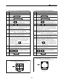
Sensor
Paper size
A3
B4
A4R
B5R
A4
B5
PS302
PS25
PS303
PS26
●
●
●
×
×
×
●
●
×
×
×
×
: Paper is detected (ON).
✕ : Paper is not detected (OFF).
b.
APS detection timing
The APS detection timing differs depending upon
whether the platen mode or the DF mode is used.
(1) During a DF copy operation
When either the DF mode is selected or an original is
placed in the RADF paper feed tray, the original size
is detected by PS302 (original size detect 1), PS303
(original size detect 2) and VR301 (original size
detect).
Paper exit side
(2) During a platen copy operation
• When PS4 (APS timing) is ON and PS301 is ON
• If RADF is open, the original size is detected when
the Start button is pressed.
: Photosensor
: LED
The relation between each sensor and the paper size
is shown below.
2-C-6
READ SECTION
2.
Signals
[7] AES Control
a. Input signals
(1) OPT HOME (PS3 to SCDB to ICB)
Exposure unit home position detection signal
[L]: Exposure unit is in the home position.
[H]: Exposure unit is not in the home position.
5VDC
28VDC
SGND
PGND
12VDC
SGND
(2) APS TIMING (PS4 to SCDB to ICB)
RADF opening/closing detection signal
Activates or deactivates the APS function at a platen
copy operation.
[L]: OFF (APS function deactivated)
[H]: ON (APS function activated)
DCPS2
DCPS1
GND
(3) APS DATA 2 (PS25 to SCDB to ICB)
Paper size detection signal
[L]: Paper is detected.
[H]: Paper is not detected.
SD0
SD1
/SEN
(4) APS DATA 3 (PS26 to SCDB to ICB)
Paper size detection signal
[L]: Paper is detected.
[H]: Paper is not detected.
CCD
RCK
GND
TCK
CB
ICB
GND
ADB
When an AE scanning takes place, the CCD sensor
installed on the ADB (A/D converter board) reads the
original density, and the ICB (image control board)
performs processing corresponding to the read
results and selects the optimum γ correction curve for
the original reproduction. This operation is called AE
control. The selection of this γ correction curve is
done by the CPU on the ICB.
2-C-7
READ SECTION
1.
Operation
a. AES detection operation
(1) During a platen copy operation
When the Start button is pressed, an AE scanning
takes place, and the density of the original is read
over the following range.
<AES sampling range>
1)
When RADF is open
Range of non-image area erace mode, or the
inside of the area detected by the APS
2)
When RADF is closed
• Range of 20 mm inward of the original size
detected by the APS
• If the original size cannot be determined by the
APS, a range of 20 mm inward of the minimum
original size set for the particular shipping
destination of the machine.
(2) During a DF copy operation
The image at the leading edge of the original is read
by the original feed operation that takes place when
the Start button is pressed, and the read data is used
to perform density measurement.
<AES sampling range>
1)
Main scanning direction
• A range of 20 mm inward of the original size
detected by the APS
• If the original size cannot be determined by the
APS, a range of 20 mm inward of the minimum
original size set for the particular shipping
destination of the machine.
2)
Sub scanning direction
Range between 1.5 mm and 2.9 mm from the
leading edge of the original
2-C-8
WRITE UNIT
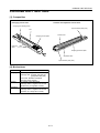
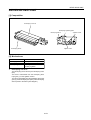
WRITE UNIT
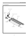
[1] Composition
Dust-proof glass
fθ lens
Write mirror
Index mirror
Cylindrical lens 2
Index sensor board
Collimator lens unit
Laser drive board
Polygon mirror
Cylindrical lens 1
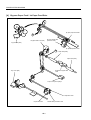
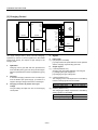
[2] Mechanisms
Mechanisms
Scan *1
Light source
Positioning
Cylindrical lens 2
Write mirror
fθ lens
Methods
Polygon mirror
Rotational speed:
· 49606.3 rpm
Laser diode (1)
· Output : Max. 5 mW
· Wavelength : 780 nm
Index sensor
Polygon mirror
Dust-proof
glass
Cylindrical
lens 1
*1: Path of laser beam
Collimator lens unit
The light output from the semiconductor laser is sent
to the OPC drum via the collimator lens, cylindrical
lens 1, polygon mirror, fθ lens, cylindrical lens 2, and
write mirror.
Index mirror
Laser diode
Index sensor board
Write mirror
Polygon mirror
Cylindrical lens 2
OPC drum
fθ lens
2-D-1
Dust-proof
glass
WRITE UNIT
2. Signals
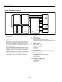
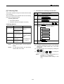
[3] M5 (Polygon) Control
a. Input signals
(1) POLY PULL LOCK (PMDB to SCDB)
M5 rotation speed monitoring signal
[L]: Normal rotation
[H]: Stop or rotation abnormality
POLY CONT
M5 DRIVE A
POLY PLL LOCK
M5 DRIVE B
POLY CLK
M5 DRIVE C
(2) M5 MAG A/A' (M5 to PMDB)
M5 MAG B/B' (M5 to PMDB)
M5 MAG C/C' (M5 to PMDB)
These are output signals from the position sensors
(magnetic sensors) installed inside M5. The PMDB
detects the position of the rotor of the motor by
means of these signals, and switches over the M5
DRIVE A to C output.
M5 MAG C
M5 MAG C'
SCDB
M5 MAG B
M5
M5 MAG B'
M5 MAG A
24VDC
M5 MAG A'
PGND
12VDC
SGND
DCPS1
PMDB
b. Output signals
(1) POLY CONT (SCDB to PMDB)
This signal controls the ON/OFF state of M5.
[L]: M5 ON
[H]: M5 OFF
M5 (polygon) is driven by the PMDB (Polygon motor
drive board), and is controlled by the SCDB (scanner
drive board).
1.
Operation
a.
M5 is a 3-phase brushless DC motor which is driven
using a 3-phase bipolar method. The current flowing
through the windings is switched according to the
position of the rotor which is detected by a sensor
(magnetic sensor) inside the motor.
This motor rotates the polygon mirror, causing the
laser beam from LDB (lazer drive board) to be
scanned in the axial direction of the drum. The
speed of the motor is maintained constant by PLL
control.
M5 is powered by 24 VDC. The rotational speed is
as follows.
b.
State of the machine
During copy
During idling
(2) POLY CLK (SCDB to PMDB)
This is a reference clock signal for PLL-controlling M5
in the PMDB.
(3) M5 DRIVE A to C (PMDB to M5)
This is the drive output signal for M5. While M5 is
rotating, voltages are output sequentially from M5
DRIVE A to C, and applied to M5.
The voltage from each output that is applied to M5
consists of the pulses shown below. The pulse width
of this output changes according to the rotation
condition of M5, as shown in the figure, and as a
result the RMS value of the voltage applied to M5
changes, causing the speed to be regulated.
Rotational speed
49606.3 rpm
One of the following three
speeds can be selected
using the “25” mode.
• 49606.3 rpm
• 25000 rpm *
• Stop *
* If the item marked * is selected, the rotational
speed of M5 switches over after the lapse of the
specified time from the completion of the warm-up
or the end of the copy process.
The specified time can be selected using the “25”
mode among below.
· 15 sec, 30 sec, 60 sec, 120 sec
2-D-2
WRITE UNIT
(3) Shading correction
<Implementation timing>
White correction, Black correction
• When SW2 is ON
• Before job
(4) Brightness/density conversion
(5) AES processing
(6) Text/dot pattern judgement
(7) Filtering
(8) Magnification change processing
(9) Copy γ correction
(10) Write density control
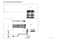
[4] Image Write Control
5VDC
SGND
/S/H
/ENB
/VIDEO
VIDEO
/ALM
N.C.
DACLK
DI
LD
5VDC
LDB
b.
5VDC
SGND
/INX
SGND
IDPR 5VDC
INDEXSB
ADB
(1) MPC (Maximum Power Control)
The ICB instructs the LDB to cause the laser to
output the maximum power output value, thus setting
the maximum output value. The LDB stores this
setting, and maintains the laser light intensity stored
by means of the APC (Automatic Power Control)
operation.
CB
ICB
The analog image data from the CCD sensor is A/Dconverted and processed by the ADB (A/D converter
board). The processed image data is memorized by the CB
(control board), then returned to the ICB (image control
board) once again and converted into a laser record signal.
The laser record signal is transmitted via the CB to the LDB
(Laser drive board) by the control signal from the ICB, and
output as an optical signal from the laser installed on the
LDB. The write start position of the laser record signal is
detected by INDEXSB (index sensor board).
1.
Operation
a.
Image processing
The following processing is carried out by the ICB.
Write
The ICB sends image data one pixel at a time to LDB
in accordance with control signals from the CB.
LDB cause the laser to emit at a time period
corresponding to the image data. This laser light is
applied to the drum.
<MPC timing>
•
When SW2 is turned ON.
(2) APC (Automatic Power Control)
The ICB outputs an APC start instruction to the LDB
at the following timing, after MPC is set.
<APC timing>
• When PLL lock of M5 (polygon) is detected.
After PLL lock is detected, the LDB automatically
monitors the laser drive current one line at a time,
and controls it so that the light intensity remains the
MPC value.
(3) Write Timing
In this machine, the INX signal from INDEXSB
determines the laser write start timing for each scan
in the axial direction of the drum.
(1) AOC (Automatic Offset Correction)
IC on ADB automatically adjusts analog off set
voltage of CCD sensor output.
(2) AGC (Automatic Gain Correction)
When SW2 (sub power) is turned ON, the white
reference plate is read, and the amplification of the
analog output from the CCD sensor is automatically
adjusted so that the resulting level is the upper limit of
the A/D converter.
2-D-3
WRITE UNIT
2.
Signals
a. Input signals
(1) INX (INDEXSB to CB to ICB)
Write system index signal
(2) IDPR (INDEXSB to CB to ICB)
5 VDC power monitoring signal for INDEXSB (index
sensor board)
(3) ALM (LDB to CB to ICB)
Signal which indicates an abnormality in the laser
drive current (APC operation).
[L]: Abnormal
[H]: Normal
b. Output signals
(1) VIDEO (ICB to CB to LDB)
Laser image data signal
(2) DA CLK (ICB to CB to LDB)
Data transfer clock signal for MPC setting value
(3) DI (ICB to CB to LDB)
Data signal of MPC setting value
(4) LD (ICB to CB to LDB)
Storage directive signal for MPC setting value
(5) S/H (ICB to CB to LDB)
APC sampling signal for one line scan
(6) ENB (ICB to CB to LDB)
Laser APC function ON/OFF control signal
While this signal is OFF then the laser beam output is
prohibited.
2-D-4
DRUM UNIT
DRUM UNIT
[1] Composition
Charging corona unit
Separation claws
Charge cleaning knob
Developing unit
PCL Charging corona unit
Cleaning unit
Developing unit
Cleaning unit
Transfer/separation
corona unit
Drum
TSL
[2] Mechanisms
Mechanisms
Carriage support
PCL
Auxiliary separation
Methods
Fixed rail
LED
Separation claws
The drum unit of this machine is an integral assembly
consisting of the drum, and also the charging corona unit,
developing unit, cleaning unit, toner recycle unit and the
PCL which are installed around the drum.
2-E-1
Drum
DRUM UNIT
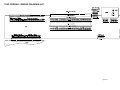
[3] PCL/TSL Control
[4] Separation Claw Control
24VDC
24VDC
PGND
PCL CONT
24VDC
TSL DRIVE
PCL
24VDC
24VDC
PGND
SD1 DRIVE
TSL
24VDC
MC1 DRIVE
24VDC
MC1 DRIVE
SD1
MC1
MC1
SGND
PS16 SIG
PS16
5VDC
DCPS1
DCPS1
PRDB
The PCL (pre-charging lamp) and TSL (transfer
synchronization lamp) consist of LEDs which are
controlled by the PRDB (printer drive board).
The separation claws are driven by SD1 (separation claw),
and is controlled by the PRDB.
1.
1.
Operation
Operation
SD1 goes ON after the specified time from when MC1
goes ON, causing the separation claws to touch the
drum in order to help separate the paper from the drum.
PCL goes ON after the specified time from when the
Start print button is pressed, and goes OFF again
after the specified time from the turning OFF of PS16
(registration) upon the final copy exit.
TSL goes ON after the specified time from when MC1
(registration) goes ON, and goes OFF again after the
specified time from PS16 going OFF.
2.
PRDB
2. Signals
a. Output signal
(1) SD1 DRIVE (PRDB to SD1)
SD1 drive control signal
[L]: SD1 ON
[H]: SD1 OFF
Signals
a. Output signals
(1) PCL CONT (PRDB to PCL)
PCL ON/OFF control signal
[L]: PCL ON
[H]: PCL OFF
(2) TSL DRIVE (PRDB to TSL)
TSL drive control signal
[L]: TSL ON
[H]: TSL OFF
(3) MC1 DRIVE (PRDB to MC1)
MC1 drive control signal
[L]: MC1 ON
[H]: MC1 OFF
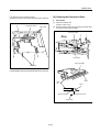
2-E-2
DRUM UNIT
[5] Transfer Entrance Guide Plate Control
5VDC
28VDC
24VDC
SGND
PGND
PGND
PGND
24VDC
PGND
5VDC
24VDC
CONT
PGND
LOCK SIG
M1
SGND
M1 CLK
DCPS2
DCPS1
GP
SGND
GP
GP CONT
5VDC
HV2
SGND
PS16 SIG
CB
ICB
SCDB
PRDB
A constant voltage is applied to the transfer guide plate in
order to prevent toner from adhering to it.
1.
Operation
a.
ON/OFF timing
Transfer guide plate control goes ON after the
specified time from when the Start button is pressed,
and goes OFF again after the specified time from
PS16 (registration) goes OFF.
b.
Applied voltage
–500 VDC
2.
Signals
a. Output signals
(1) GP CONT (PRDB to HV2)
Signal for controlling ON/OFF of the voltage applied
to the paper transfer guide plate.
[L]: Voltage is applied.
[H]: Voltage is not applied.
2-E-3
5VDC
PS16
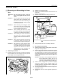
CORONA UNIT SECTION
CORONA UNIT SECTION
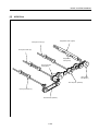
[1] Composition
<Charging corona unit>
<Transfer and separation corona unit>
Charging wire cleaning block
Spark arrestor plate (front)
PCL
;;
;;
Transfer wire
Charging control plate
Charging
wires
Plunging prevention plate
Separation wire
Spark arrestor plate (rear)
[2] Mechanisms
Mechanisms
Method
Charging
Scorotron (DC negative corona discharge)
Discharge wire: Tungsten 0.06 mm dia.
(gold-plated skin path)
Grid control: Stainless steel plate
With manual wire cleaner
Transfer
DC positive corona discharge
Discharge wires: Tungsten 0.06 mm dia.
(protection by a tough film of oxide)
Separation
AC/DC corona discharge
Discharge wires: Tungsten 0.06 mm dia.
(protection by a tough film of oxide)
2-F-1
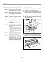
CORONA UNIT SECTION
[3] Charging Control
5VDC
28VDC
SGND
PGND
24VDC
PGND
24VDC
PGND
M4
5VDC
24VDC
CONT
PGND
LOCK SIG
PGND
M4 CLK
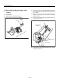
DCPS2
DCPS1
CHARGING
C CONT
C SHIFT
SGND
G SHIFT
5VDC
F(C) SIG
GRID
HV1
SGND
PS16 SIG
CB
ICB
SCDB
PRDB
HV1 (high voltage unit/1), which controls charging,
operates by means of control signals from the PRDB
(printer drive board), and outputs a high voltage to the
charging wires.
1.
2.
5VDC
PS16
Signals
a. Input signal
(1) F(C) SIG (HV1 to PRDB)
[L] is output when the spark detection circuit operates
and the charging output forcibly goes OFF.
Operation
Charging control goes ON after the specified time
from when M4 (drum) goes ON, and goes OFF again
after the specified time from PS16 (registration) going
OFF.
b. Output signals
(1) C CONT (PRDB to HV1)
Charging and grid voltage ON/OFF control signal
[L]: Charging and grid voltage ON
[H]: Charging and grid voltage OFF
a.
Charging
A Scorotron charging method is used. 24 VDC input
from the DCPS1 (DC power supply 1) is raised to a
negative DC high voltage which is then discharged.
(2) C SHIFT (PRDB to HV1)
The charging corona unit output level is controlled by
means of analog signals from the PRDB.
b.
Charging correction by means of the grid
voltage
The grid voltage is output from HV1 to the charging
control plate.
C SHIFT output range
Charging output range
4 to 10 V
–550 to –1200 µA
(3) G SHIFT (PRDB to HV1)
The charging grid voltage output level is controlled by
analog signals from the PRDB.
G SHIFT output range
Grid voltage output range
2-F-2
4 to 10 V
–500 to –900 V
CORONA UNIT SECTION
[4] Transfer/Separation Control
5VDC
28VDC
24VDC
SGND
PGND
PGND
SEPARATION
T CONT
TRANSFER
T SHIFT
S CONT
24VDC
S(AC) SHIFT
PGND
S(DC) SHIFT
F(T) SIG
F(S) SIG
DCPS2
HV2
DCPS1
24VDC
MC1 DRIVE
SGND
MC1
5VDC
SGND
PS16 SIG
5VDC
CB
ICB
SCDB
PRDB
2.
Transfer and separation corona unit are controlled by the
PRDB (printer drive board) and HV2 (high voltage unit/2).
1.
Transfer and separation corona discharge go ON after
the specified time from when MC1 (registration) goes
ON, and goes OFF again after the specified time from
PS16 (registration) going OFF.
Transfer
A positive DC high voltage is used for transfer.
b.
Separation
An AC high voltage is used for separation.
Signals
a. Input signals
(1) F(T) SIG (HV2 to PRDB)
[L] is output when the transfer spark detection circuit
operates.
Operation
a.
PS16
(2) F(S) SIG (HV2 to PRDB)
[L] is output when the separation spark detection
circuit operates.
2-F-3
CORONA UNIT SECTION
b. Output signals
(1) T CONT (PRDB to HV2)
Transfer corona unit ON/OFF control signal.
When this signal is [L], the transfer corona unit goes
ON.
(2) T SHIFT (PRDB to HV2)
Transfer corona unit output level control signal
This signal controls the transfer corona unit output
level using analog signals from the PRDB (printer
drive board).
T SHIFT output range
4 to 10 V
Transfer voltage output range 40 to 450 µA
(3) S CONT (PRDB to HV2)
Separation corona unit ON/OFF control signal
When this signal is [L], the separation corona unit
goes ON.
(4) S SHIFT (AC) (PRDB to HV2)
Separation corona unit output level control signal
This signal controls the separation corona unit output
level (AC component) using analog signals from the
PRDB.
S SHIFT (AC) output range
Separation AC voltage
output range
4 to 10 V
2.8 to 5.5 kV
(5) S SHIFT (DC) (PRDB to HV2)
Separation corona unit output level control signal
This signal controls the separation corona unit output
level (DC bias component) using analog signals from
the PRDB.
S SHIFT (DC) output range
Separation DC bias voltage
output range
4 to 10 V
0 to –300 µA
2-F-4
DEVELOPING UNIT
DEVELOPING UNIT
[1] Composition
Developing unit cover
Developing regulating plate
Developing sleeve
Agitator wheel
Developing sleeve
[2] Mechanisms
Mechanisms
Developing
Developing bias
Developer agitation
1.
Agitator screws
Methods
2-component developer
DC bias
Main agitation
Auxiliary agitation
Developing unit drive
The developing unit is driven by the developing motor
(M3).
The drive is transmitted from the developing drive
input gear (1) to the agitation section.
The drive is transmitted from the developing drive input
gear (2) via the developing MC (MC2) to the developing
sleeve. (Refer to the drive system diagram.)
2-G-1
DEVELOPING UNIT
[3] M3 (Developing) Control
5VDC
28VDC
SGND
PGND
PGND
PGND
24VDC
24VDC
5VDC
PGND
SGND
M3
CONT
CLK
MODE
DCPS2
LD
DCPS1
SGND
SGND
5VDC
PS16 SIG
PS16
5VDC
24VDC
MC2 DRIVE
CB
ICB
SCDB
PRDB
2.
M3 (developing) is controlled by the PRDB (Printer
drive board).
1.
MC2
Signals
a. Input signal
(1) LD (M3 to PRDB)
M3 rotational status detection signal
This signal becomes [L] when M3 reaches the set
speed.
Operation
M3 is a 24 V drive DC motor which drives the
developing sleeve, agitator wheel and agitator screw.
M3 is PLL-controlled by feedback signals from a
speed sensor installed inside M3 itself, maintaining it
at a constant speed.
M3 goes ON after the specified time from when the
Start button is pressed, and goes OFF again after the
specified time from the completion of charging
control.
MC2 (developing) goes ON after the specified time
from when M3 goes, and goes OFF again after the
specified time from PS16 (registration) going OFF
b. Output signals
(1) CONT (PRDB to M3)
M3 drive control signal
[L]: M3 ON
[H]: M3 OFF
(2) CLK (PRDB to M3)
M3 rotational speed control reference clock signal
(3) MODE (PRDB to M3)
M3 rotational speed switching signal
[L]: High speed
[H]: Low speed
(4) MC2 DRIVE (PRDB to MC2)
MC2 drive control signal
[L]: MC2 ON
[H]: MC2 OFF
2-G-2
DEVELOPING UNIT
[4] Developing Bias Control
5VDC
28VDC
SGND
PGND
PGND
PGND
24VDC
24VDC
5VDC
PGND
SGND
M3
CONT
CLK
MODE
DCPS2
LD
DCPS1
24VDC
SGND
5VDC
BIAS
PGND
B CONT
B SHIFT
HV2
SGND
PS16 SIG
CB
ICB
SCDB
PRDB
The developing bias is controlled by the PRDB (printer
drive board) via the HV2 (high voltage unit/2).
1.
Operation
The developing bias is applied to the sleeve after the
specified time from when the M3 (developing) goes
ON, and goes OFF again after the specified time from
PS16 (registration) going OFF
2.
Signals
a. Output signals
(1) B CONT (PRDB to HV2)
Developing bias ON/OFF control signal
When this signal is [L], the developing bias goes ON,
and a high voltage is output.
(2) B SHIFT (PRDB to HV2)
Developing bias level control signal
This signal controls the output level of the developing
bias by means of analog signals from the PRDB.
B SHIFT output range
Bias voltage output range
2 to 8 V
–400 to –700 VDC
2-G-3
5VDC
PS16
DEVELOPING UNIT
[5] Toner Density Control
5VDC
28VDC
SGND
PGND
PGND
PGND
24VDC
12VDC
SGND
24VDC
5VDC
PGND
SGND
M3
CONT
CLK
MODE
DCPS2
LD
DCPS1
24V (A)
12VDC
24V (A)
M11
SGND
5VDC
TDS CONT
12VDC
TONER ANG SIG
TDS
SGND
CB
ICB
SCDB
PRDB
SGND
PS16 SIG
5VDC
PS16
24VDC
MC2 DRIVE
b.
The toner density is controlled by the TDS (toner density
sensor), M11 (toner supply 2) and the PRDB (printer drive
board).
1.
Operation
a.
Toner density detection
The TDS detects the density of the toner in the
developing unit using an L detection method, and
outputs an analog voltage signal that is proportion to
the density to the PRDB.
The PRDB compares the detected voltage with the
reference voltage corresponding to the initial density
of the developer, and judges the necessity of
supplying toner.
MC2
Toner supply operation to the developing unit
M11 is driven by 24 VDC supplied from the PRDB.
(1) When the power is switched ON
After the power is switched ON and the agitator
screw is driven by the M3 (developing) via the MC2
(developing), then after the specified time the toner
density is read.
This density is compared with the initial density of the
developer, and if the density is low, M11 goes ON
and toner supply takes place. (recovered until its
initial density)
(2) During a copy operation
The relationship between the TDS output voltage and
the toner supply time is as follows.
TDS output voltage
1.99 V or lower
2.00 to 2.09 V
2.10 to 2.17 V
2.18 to 2.27 V
2.28 to 2.34 V
2.35 to 2.42 V
2.43 V or higher
2-G-4
Toner supply time
0 sec
0.24 sec
0.48 sec
0.72 sec
0.96 sec
1.20 sec
1.80 sec
DEVELOPING UNIT
2.
Signals
a. Input signal
(1) TONER ANG SIG (TDS to PRDB)
An analog voltage proportional to the toner density is
output.
b. Output signals
(1) TDS CONT (PRDB to TDS)
TDS (toner density sensor) output voltage adjustment
signal
Output voltage range: 3 to 8 V
(2) M11 (A, A) (PRDB to M11)
M11 (toner supply 2) drive control signal
2-G-5
DEVELOPING UNIT
[6] Dmax Control
5VDC
28VDC
24VDC
SGND
PGND
PGND
PGND
12VDC
PGND
SGND
24VDC
5VDC
PGND
SGND
M3
CONT
CLK
MODE
DCPS2
LD
DCPS1
12VDC
SGND
5VDC
5VDC
SGND
M4
CONT
CLK
LOCK SIG
CB
ICB
PRDB
SCDB
DRUM TH 5VDC
DRUM TH
12VDC
IF
SIG/1
SIG/2
TCSB
SGND
2. Signals
Dmax control is carried out by the TCSB (toner control
sensor board), M4 (drum), M3 (developing), and so on.
These parts are controlled by the PRDB (printer drive
board).
1.
a. Input signals
(1) SIG 1 (TCSB to PRDB)
This signal monitors the light reflected from the surface of
the drum (without toner), and corrects the voltage applied
to the PD1 so that the output becomes 6 V (calibration).
Reference voltage: 6 V
Operation
Dmax control is intended to align the maximum
density for each machine with the reference level.
(2) SIG 2 (TCSB to PRDB)
Output voltage of the PD1 on the TCSB
Reference voltage: 1.5 V
(1) Contents of implementation
Latent images are created several times at the
maximum exposure, the images are developed while
the rotational speed of the sleeve is varied, then each
density is read by the PD1 (Dmax senser) on the
TCSB.
The rotational speed of the sleeve when the density
reaches the reference level is memorized as the
optimum sleeve speed, then subsequently
developing is carried out at this sleeve speed until
Dmax correction takes place next.
<Implementation timing>
Calibration takes place before Dmax correction.
(3) DRUM TH (TCSB to PRDB)
Drum surface temperature detection analog signal
b. Output signals
(1) IF (PRDB to TCSB)
Dmax value detection LED ON/OFF control signal
[L]: LED ON
[H]: LED OFF
(2) Implementation timing
a) When the power is switched ON
b) At 500 copies
c) At 1000 copies
2-G-6
DEVELOPING UNIT
[7] Gradation Correction Control
24VDC
5VDC
28VDC
PGND
SGND
PGND
PGND
12VDC
PGND
SGND
24VDC
5VDC
SGND
SGND
28VDC
CONT
M3
CLK
PGND
MODE
LD
DCPS1
DCPS2
5VDC
12VDC
SGND
SGND
M4
CONT
5VDC
M4 CLK
LOCK SIG
DRUM TH 5VDC
DRUM TH
12VDC
IF
CB
ICB
SCDB
SIG1
TCSB
SIG2
SGND
24VDC
A
A
B
M2
B
24VDC
SGND
L1 CONT
OPT HOME
PS3
5VDC
PGND
LAMP ON/OFF
L1 INVB
24VDC
LV
L1
HV
CCD
ADB
Gradation correction control is intended to stabilize the
reproduction density of halftone for each machine.
Operation
Copy density
1.
Gradation density control is an operation in which the
gradation characteristics of the developing toner
density with respect to the exposure in the image
forming section (the drum and peripheral units) are
detected, then processed so that the relationship
between the original density and the copy density is
linear.
0
255
Original density signal
2-G-7
DEVELOPING UNIT
(1) Contents of implementation
1) During initial adjustment (adjustment by the service
mode)
During image quality adjustment in the 36 mode, an
SGU test pattern (before gradation correction) is
output, and read by the scanner (CCD) and
memorized.
(For details, refer to the “Adjustment section” in
Field Service.)
2)
During normal operation (automatic adjustment)
Toner patch patterns (gradation patterns) of
different densities are formed on the drum, and
each toner patch density is read by the Dmax
sensor and memorized as drum gradation data.
The gradation correction value is computed based
on the gradation data of the SGU test pattern read
by the CCD and the drum gradation data read by
the Dmax sensor, and used to optimally correct the
laser output.
(2) Implementation timing
1) Initial adjustment
When the drum, PRMB (parameter memory board)
or TCSB (toner control sensor board) developer is
replaced
2)
Normal operation
a) When the power is switched ON
b) At 500 copies
2-G-8
TONER SUPPLY UNIT
TONER SUPPLY UNIT
[1] Composition
Toner cartridge
Shutter
Pressure lever
[2] Mechanisms
Mechanisms
Toner supply
Toner level detection
Toner agitation *1
Toner cartridge*2
Toner leakage
prevention
Methods
Screw conveyance
Piezoelectric method 120g±20g
Agitation plate
Rotating cartridge method
Capacity 600g
Toner supply shutter
Toner cartridge
Toner supply motor 1
One-way
clutch
*1: Toner agitation
The drive is transmitted from the following two motors
via a gear group to the agitation plate.
a. Toner supply motor 1 (M10)
For toner cartridge drive
Toner supply
motor 2
b. Toner supply motor 2 (M11)
For toner conveyance screw drive
The agitation plate rotates faster in rotation of the
toner supply motor 2 than the toner supply motor 1.
When two motors rotate simultaneously, the drive of
the M10 is transmitted by theone way clutch to the
agitation plate shaft.
2-H-1
Agitation plate
Toner conveyance
screw
TONER SUPPLY UNIT
*2: Toner cartridge
When the toner cartridge rotates, toner moves to the
cartridge exit along the spiral groove marked on the
surface of the toner cartridge.
When the cartridge points down, toner flow to the
toner supply unit agitation and conveyance section.
Exit
45° rotating
Toner is supplied to the agitation/conveyance
section of the toner supply unit.
2-H-2
TONER SUPPLY UNIT
[3] Toner Level Detection Control
5VDC
28VDC
24VDC
SGND
PGND
PGND
M10
24VDC
CONT
PGND
UNLOCK SIG
TONER LEVEL 5V
DCPS2
TONER LEVEL SIG
DCPS1
TLD
SGND
SGND
5VDC
24V (A)
24V (A)
CB
ICB
PRDB
SCDB
2.
Toner level detection control is carried out by the TLD (toner
level detector) and PRDB (printer drive board).
1.
a.
b.
(2) UNLOCK SIG (M10 to PRDB)
M10 rotational status detection signal
This signal becomes [L] when M10 reaches the set
speed.
Detection timing
The detection timing is as follows.
· When the machine is switched ON
b. Output signals
(1) CONT (PRDB to M10)
M10 drive control signal
[L]: M10 ON
[H]: M10 OFF
· When the front door is opened and closed
· During a copy operation
Toner supply operation to toner supply unit
When TLD detects a no-toner condition, M10 (toner
supply 1) goes ON and supplies toner.
d.
Detection of no toner state in toner cartridge
It the no toner state is detected by TLD after M10 has
been held ON for a specified period of time, the toner
cartridge is assumed to be empty.
Signals
a. Input signals
(1) TONER LEVEL SIG (TLD to PRDB)
When the level of toner in the toner supply unit
becomes low, this signal becomes [L], and a
message is displayed on the LCD connected to OB.
Operation
Toner level detection
A piezoelectric device is used as the TLD.
When the level of toner in the toner supply unit
becomes low, the “supply toner” signal is output to
the PRDB. As a result, a message is displayed on
the LCD (display board) via the OB (operation board).
c.
M11
2-H-3
CLEANING/TONER RECYCLE UNIT
CLEANING/TONER RECYCLE UNIT
[1] Composition
Cleaning blade
Cleaning blade
Toner conveyance
screw
Toner collection sheet
Toner recycle screw
[2] Mechanisms
Mechanisms
Drum cleaning
Toner recycle
Toner collection
Methods
Cleaning blade (Fixed type)
Screw conveyance to the
developing unit
Toner collection sheet
2-I-1
PAPER FEED UNIT
PAPER FEED UNIT
[1] Composition
<By-pass tray unit>
By-pass tray
By-pass paper
feed roller
By-pass separation
<Paper feed unit>
roller
Separation roller
Double feed
prevention roller
Paper feed roller
By-pass
double feed
prevention
roller
<2nd paper feed unit>
By-pass SD
Registration roller
(upper)
Registration roller
(lower)
By-pass separation
roller
By-pass paper
feed roller
By-pass double feed
prevention roller
Registration
paper feed roller
Double feed
prevention plate
Registration
roller (upper)
Registration
roller (lower)
Separation roller
Registration paper
feed roller
Paper feed
roller
Paper conveyance
roller
Paper lift-up plate
Paper conveyance roller
2-J-1
Double feed
prevention roller
PAPER FEED UNIT
[2] Mechanisms
Mechanisms
Paper lift pressure reduction
Paper lift-up
Double feed prevention
Tray loading
1st paper feed
2nd paper feed
By-pass paper feed
Paper size detection
(universal tray)
By-pass tray size
detection
Methods
Paper feed roller
Paper lift-up plate
Torque limiter
Front loading
Paper feed roller, 1st paper
feed SD
Registration roller, registration
clutch
Paper feed roller, By-pass
paper feed SD
Tray detection switch
(tact switch)
Paper size detection PS
Paper size detection VR
2-J-2
PAPER FEED UNIT
[3] Paper Feed Control
PGND
5VDC
24VDC
PGND
SGND
PGND
24VDC
PGND
PGND
24VDC
PGND
PGND
24VDC
PGND
24VDC
M1
24VDC
DCPS2
24VDC
5VDC
SGND
24VDC
CONT
PGND
DCPS1
M1 CLK
LOCK SIG
SGND
5VDC
5VDC
M6
SGND
M6 CONT
M6 CLK
M6 H/L
CB
ICB
24VDC
SD4 DRIVE
24VDC
24VDC
MC1 DRIVE
SD4
MC1
A
M2
A
SGND
B
PS14 SIG
B
PS14
5VDC
24VDC
SGND
SGND
PS3
PS16 SIG
OPT HOME
PS16
5VDC
5VDC
SCDB
PS17 SIG
PRDB
The 1st paper feed takes place as a result of the
transmission of drive force from M6 (1st paper feed) via
SD2 (1st paper feed) and SD4 (by-pass) to the respective
paper feed roller and separation roller. At this time, each
paper feed roller is not contact with the paper, hence the
paper feed roller and the by-pass plate are moved up and
down by SD2 and SD4, causing each roller to contact with
the paper. Control of each roller is carried out by the PRDB
(printer drive board). The 2nd paper feed is carried out by
MC1 (registration). Related signals are PS3 (optics HP),
PS14 (open close detection), PS16 (registration) and
PS17 (no feed).
2-J-3
PS17
SD2 DRIVE
24VDC
24VDC
SD2 DRIVE
PFDB
SD2
PAPER FEED UNIT
1.
2.
Operation
a. 1st paper feed operation timing (by-pass)
(1) 1st copy start
After the specified time from when the Start button is
pressed
Signals
a. Input signals
(1) PS14 SIG (PS14 to PRDB)
Paper feed door open/close detection signal
[L]: Door is closed
[H]: Door is open
(2) 2nd copy start
After the specified time from when SD4 (by-pass)
goes ON for the 1st copy
(2) PS17 SIG (PS17 to PRDB)
Paper detection signal used for detecting the paper at
before registration section.
[L]: Paper is not detected
[H]: Paper is detected
(3) OFF timing
After the specified time from when SD4 goes ON
b. 1st paper feed operation timing (tray 1)
(1) 1st copy start
After the specified time from when the Start button is
pressed
b. Output signals
(1) M6 CONT (PRDB to M6)
M6 (1st paper feed) drive control signal
[L]: M6 ON
[H]: M6 OFF
(2) 2nd copy start
After the specified time from when SD2 (1st paper
feed) goes ON for the 1st copy
(2) M6 H/L (PRDB to M6)
M6 rotational speed switching signal
[L]: High speed
[H]: Low speed
(3) OFF timing
After the specified time from when SD2 goes ON
(3) M6 CLK (PRDB to M6)
Reference clock signal for controlling the speed of
M6
c. 2nd paper feed control (MC1)
(1) ON timing
After the specified time from when V-Valid signal
goes ON
(4) SD4 DRIVE (PRDB to SD4)
SD4 drive control signal
[L]: SD4 ON
[H]: SD4 OFF
(2) OFF timing
After the specified time from when MC1 (registration)
goes ON
(5) SD2 DRIVE (PRDB to PFDB to SD2)
SD2 drive control signal
[L]: SD2 ON
[H]: SD2 OFF
2-J-4
PAPER FEED UNIT
[4] Paper Up-down Control
5VDC
24VDC
24VDC
SGND
PGND
PGND
DCPS2
DCPS1
SGND
24VDC
M8 DRIVE
M8 DRIVE
M8
24VDC
PS32 SIG
SGND
PS32
5VDC
5VDC
SW101
SIZE A
SW102
SIZE B
SIZE C
SW103
SIZE D
CB
ICB
SCDB
2.
When a paper feed tray is loaded, M8 (tray) goes ON for a
certain period, raising the bottom plate in the tray.
Related signal is PS32 (upper limit detect).
1.
Operation
a.
ON timing
M8 is turned ON by the SW101 to 104 (paper size
detection) going ON.
b.
PFDB
PRDB
SW104
Signals
a. Input signals
(1) PS32 SIG (PS32 to PFDB to PRDB)
Tray upper limit detection signal
The paper in the tray is raised by M8, and when it
reaches the upper limit position this signal becomes [H].
(2)
SIZE A, B, C, D (SW101, 102, 103, 104 to PFDB to PRDB)
Paper size detection switch ON/OFF signal
b. Output signals
(1) M8 DRIVE (PRDB to PFDB to M8)
M8 drive control signal
[L]: M8 ON
[H]: M8 OFF
OFF timing
M8 is turned OFF by PS32 going ON.
2-J-5
PAPER FEED UNIT
[5] Paper Size Detection Control
5VDC
28VDC
24VDC
SGND
PGND
PGND
PS SIG
PS27
5VDC
VR1 ANG SIG
VR1
SGND
DCPS2
DCPS1
SGND
SIZE A
5VDC
SW101
SIZE B
SW102
SIZE C
SIZE D
SGND
CB
ICB
SCDB
PFDB
SW103
SW104
PRDB
The size of the paper in the paper feed tray is detected as
a result of the matrix circuit in the PRDB (printer drive
board) detecting the signal from the PFDB (paper feed
detection board). The size of paper in the by-pass tray is
detected by the PRDB according to the combination of
PS27 (paper size detection (by-pass)) and VR1 (paper
size detection (by-pass)).
b.
By-pass tray paper size detection
The size in the lengthwise direction of the paper in
the by-pass tray is detected by the ON/OFF state of
PS27, and the size in the widthwise direction is
detected by the resistance of VR1 which varies
according to the position of the guide on the by-pass
tray.
1.
Operation
2.
Signals
a.
Paper feed tray 1 paper size detection
The paper feed detection board has four switches
which detect the position of the paper size detect
actuators in the paper feed tray. The paper size is
detected according to the particular ON-OFF
combination of these switches.
The relation between the state of the switches on the
paper feed detection board and the paper size is
shown below.
a. Input signals
(1) PS SIG (PS27 to PRDB)
By-pass tray lengthwise direction paper size
detection signal
[L]: 8.5 x 14 size or larger
[H]: 8.5 x 11R size or less
Paper size
11A3
x 17
8.5B4
x 14
8.5A4
x 11
B5
A4R
B5R
A5R
8.5 x 11R
(2) VR1 ANG SIG (VR1 to PRDB)
By-pass tray widthwise direction paper size detection
signal
SW101 SW102 SW103 SW104
ON
OFF
OFF
OFF
ON
OFF
OFF
ON
ON
ON
ON
ON
ON
ON
OFF
ON
OFF
ON
ON
OFF
OFF
OFF
ON
ON
OFF
ON
ON
ON
OFF
ON
OFF
ON
2-J-6
PAPER FEED UNIT
[6] No Paper Detection Control
5VDC
28VDC
24VDC
SGND
SGND
PGND
PGND
PS13 SIG
PS13
5VDC
DCPS2
DCPS1
SGND
5VDC
SGND
PS31 SIG
PS31
5VDC
CB
ICB
SCDB
PRDB
No paper detection takes place by PS31 (no paper detect)
and PS13 (no paper (by-pass)) which are controlled by the
PRDB (printer drive board).
1.
Operation
a.
No paper detection control
When a paper feed tray or the by-pass tray becomes
empty, PS31 or PS13 goes ON. As a result, a
message is displayed on the LCD (display board) via
the OB (operation board).
2.
Signals
a. Input signals
(1) PS13 SIG (PS13 to PRDB)
By-pass tray no paper detection signal
[L]: No paper in tray
[H]: Paper in tray
2-J-7
PFDB
FIXING UNIT
FIXING UNIT
[1] Composition
Fixing cleaning roller
Fixing heater lamp 1
Fixing heater lamp 2
Fixing cleaning pad
Fixing cleaning roller
Fixing roller (A)
Fixing roller (A)
Fixing claw (upper)
Fixing temperature
sensor 1
Thermostat
Fixing temperature
sensor 2
Fixing paper
exit pulley
Fixing paper exit
roller (lower)
Fixing roller (upper)
Fixing claw (lower)
Fixing roller (lower)
Paper exit roller unit (lower)
Paper exit roller unit (upper)
[2] Mechanisms
Mechanisms
Fixing
Heat source
Cleaning
Oil apply
Upper roller
Lower roller*1
Separation
Temperature detection
Overheating prevention
Neutralizing
Pressure release
lever
Methods
Pressure + heat roller
Heater lamp (Two upper lamps)
Fixing cleaning roller,
Fixing cleaning pad
Fixing roller (A) (silicone oil)
Aluminium + PFA coating
Silicone rubber + PFA tube
Separation claws (4 upper and
4 lower claws)
Upper roller
• Non-contact type thermistor
(for control)
• Contact type thermistor
(for abnormality detection)
Non-contact type thermostat
(upper roller)
Neutralizing brush
Pressure
Release
Pressure
release
lever
*1: Pressure release mechanism of the fixing
roller (lower)
Pressure
The pressure release of the fixing roller (lower) is
carried out by fixing and releasing the two rear and
front pressure release lever.
Release
2-K-1
FIXING UNIT
[3] Fixing Temperature Control
L2 DRIVE
RL
b.
Protection against abnormality
TS (thermostat) is used to prevent the temperature of
the fixing roller (upper) from rising abnormally. This
thermostat is not in contact with the fixing roller
(upper).
The operating temperature of the thermostat is
shown below.
TS: Approx. 190°C
2.
Signals
L2
L3 DRIVE
L3
AC(H)
TS
AC (H)
L2 CONT
L3 CONT
RL CONT
DCPS1
TH1 ANG1
a. Input signals
(1) TH1 ANG 1, 2 (TH1 to PRDB)
TH1 output signal
This signal outputs a voltage that is proportional to
the surface temperature at the center of the fixing
roller (upper).
This signal is used for temperature control and also
for detecting an abnormally high temperature or other
abnormality.
TH1
TH1 ANG2
TH2 ANG1
TH2
TH2 ANG2
PRDB
(2) TH2 ANG 1, 2 (TH2 to PRDB)
TH2 output signal
This signal outputs a voltage proportional to the
surface temperature at the end of the fixing roller
(upper). It is not directly related to temperature
control but is used for detecting an abnormality.
The fixing roller (upper) is heated by L2 (fixing heater lamp
1), and L3 (fixing heater lamp 2).
The PRDB (printer drive board) detects the temperature of
the fixing roller (upper) by means of TH1 (fixing temperature
sensor 1) and TH2 (fixing temperature sensor 2), and
controls L2 and L3 via DCPS1.
1.
b. Output signals
(1) L2 DRIVE (DCPS1 to L2)
L2 AC(N) supply line.
The AC supply is switched ON or OFF according to
L2 CONT.
Operation
a. Temperature control
(1) Warm-up
The PRDB turns ON the fixing heater lamp circuit in
DCPS1 (DC power supply 1) as soon as the machine
is switched ON, causing L2 and L3 to go ON until the
fixing roller (upper) reaches the specified temperature.
(2) L3 DRIVE (DCPS1 to L3)
L3 AC(N) supply line.
The AC supply is switched ON or OFF according to
L3 CONT.
(3) L2 CONT (PRDB to DCPS1)
L2 ON/OFF control signal
[L]: L2 ON
[H]: L2 OFF
After the completion of warm-up, the PRDB goes ON
and OFF repeatedly so as to maintain the set
temperature.
(Setting temperature)
195°C
(Warm up time)
Within 90 seconds (Room temperature : 20°C)
(4) L3 CONT (PRDB to DCPS1)
L3 ON/OFF control signal
[L]: L3 ON
[H]: L3 OFF
(5) RL CONT (PRDB to DCPS1)
RL (main) ON/OFF control signal
[L]: RL ON
[H]: RL OFF
2-K-2
REVERSAL AND PAPER EXIT SECTION
REVERSAL AND PAPER EXIT SECTION
[1] Composition
Switching guide
Switching guide
Paper exit cover
(upper)
Paper exit roller
Paper exit cover
(upper)
Conveyance
roller
Paper exit
reversal roller
Conveyance roller
Reversal roller
Paper exit cover
(lower)
Conveyance roller
Paper exit cover (lower)
[2] Mechanisms
Mechanisms
Paper path switching *1
Paper conveyance
a.
Methods
Switching gate
Roller conveyance
*1: Paper path switching
Paper exited from the fixing unit of the main body is
divided to straight paper exit and reversal paper exit
by the switching guide.
Reversal paper exit operation
Paper is conveyed down the paper exit cover (lower)
by the switching guide. When the trailing edge of the
paper passes the switching guide the paper exit
reversal roller rotates in the reverse direction and the
paper is exited face down.
Switching guide
The switching guide is operated by ON/OFF of the
gate SD (SD5).
Paper exit
reversal roller
Paper exit cover (lower)
2-L-1
REVERSAL AND PAPER EXIT SECTION
b.
ADU reversal operation
Paper is conveyed down the paper exit cover (lower) by
the switching guide. When the trailing edge of the paper
passes the reversal guide the reversal roller rotates in
the reverse direction and the paper is conveyed to the
ADU stacker.
Switching guide
Reversal
roller
ADU
2-L-2
REVERSAL AND PAPER EXIT SECTION
[3] Reversal Paper Exit Control
MS2
5VDC
28VDC
24VDC
24VDC
SGND
PGND
PGND
A
A
B
M12
B
24VDC
24VDC
SD5 DRIVE
DCPS2
SD5
INPORT
DCPS1
SGND
PS29 SIG
SGND
PS29
5VDC
5VDC
CB
ICB
PS SIG
PS28
PS SIG
PS30
SCDB
SGND
PS1 SIG
PRDB
Reversal and paper exit section switches the paper path to
straight paper exit or reversal paper exit by the SD5 (gate).
SD5 is driven by the PRDB (printer drive board).
Related signals are PS1 (paper exit), PS28 (reversal
detection 1), PS29 (fixing exit) and PS30 (reversal
detection 2).
1.
Operation
a.
Straight paper exit control
M12 (reversal paper exit) rotates in the forward
direction after the specified time from when PS29
goes ON. At this time, the switching guide is OFF,
hence the paper passes over the top of the switching
guide and is exited.
M12 goes OFF after the specified time from when
PS1 detects the trailing edge of the paper.
b.
2-L-3
PS1
5VDC
Paper reversal and exit control
M12 rotates in the forward direction after the
specified time from when PS29 goes ON, causing the
paper to be conveyed to the switching guide. At this
time, SD5 goes ON after the specified time from
when MC1 goes ON, causing the switching guide to
move to the paper reversal and exit side. As a result,
the paper is conveyed to the back side of the reversal
and exit section cover (lower). After the specified time
from when PS28 detects the trailing edge of the
paper and goes OFF, M12 switches to reverse
rotation, and the paper is fed in the reverse direction.
The reverse-fed paper is prevented from returning to
the fixing section by the shape of the switching guide,
and instead is fed to the paper exit section. As a
result, the paper is exited face down.
REVERSAL AND PAPER EXIT SECTION
2.
Signals
a. Input signals
(1) PS1 SIG (PS1 to PRDB)
Paper passage detection signal at the paper exit
section.
This signal becomes [H] when paper is detected.
(2) PS SIG (PS28 to PRDB)
Paper passage detection signal at the reversal roller
section.
This signal becomes [L] when paper is detected.
(3) PS29 SIG (PS29 to PRDB)
Paper passage detection signal at the fixing exit
section.
This signal becomes [H] when paper is detected.
(4) PS SIG (PS30 to PRDB)
Paper passage detection signal at the paper exit
reversal roller section.
This signal becomes [L] when paper is detected.
b. Output signals
(1) A, A, B, B (PRDB to M12)
M12 (reversal paper exit) ON/OFF drive signal
24V
0V
(2) SD5 DRIVE (PRDB to SD5)
SD5 (gate) drive control signal
[L]: SD5 ON
[H]: SD5 OFF
2-L-4
ADU SECTION
ADU SECTION
[1] Composition
Conveyance guide plate (upper)
Conveyance rollers A
Conveyance rollers C
Conveyance rollers B
Registration roller
ADU no feed PS
[2] Mechanisms
Mechanisms
Paper feed *1
Paper conveyance
Conveyance drive
Jam clearance *2
Applicable sizes of
paper
Methods
Non-stack selection
Conveyance roller (three)
Registration roller (one)
Gear+Timing belt
Opening/ closing of conveyance
guide plate (upper), entrance
guide plate (upper) and exit
guide plate (upper)
A3 to A5R, 8.5 x 14, 8.5 x 11
8.5 x 11R
From reversal and
paper exit unit
Conveyance roller A
(The drive from the ADU paper feed
motor is always transmitted to the
conveyance roller A by the timing belt. )
*1: Paper feed mechanism
ADU paper feed operation is performed by the drive
of the ADU paper feed motor (M501) and three
clutche control. (Refer to the drive system diagram.)
Loop of paper
Conveyance roller B
(clutch control)
Conveyance roller C
(clutch control + torque limiter)
(1) The paper reversed at the reversal and paper
exit section is fed to the inside of the ADU by
the conveyance roller A.
To the paper feed section
of the main body
(2) The appropriate loop of the paper is formed by
the clutch control that transmits the drive to the
conveyance rollers B and C.
(3) Paper is refed to the paper feed section of the
main body when the drive is transmitted to the
registration roller via the registration clutch.
Registration roller
(clutch control)
2-M-1
ADU SECTION
*2: Jam clearance mechanism
· Paper exit section
There is a jam clearance mechanism on each of the
conveyance section, paper feed section and paper
exit section.
Exit guide plate (upper)
Jammed paper can be removed by opening and
closing the conveyance guide plate (upper), entrance
guide plate (upper) and exit guide plate (upper),
depending upon where the jam occurres.
· Conveyance section
Conveyance guide plate (upper)
· Paper feed section
Entrance guide plate (upper)
2-M-2
ADU SECTION
[3] Conveyance Control
5VDC
28VDC
24VDC
5VDC
SGND
PGND
PGND
SGND
M501 DRIVE
M501 CLOCK
M501
M501 H/L
M501 LOCK
PGND
24VDC
DCPS2
24VDC
DCPS1
MC501 DRIVE
SGND
5VDC
24VDC
MC502 DRIVE
24VDC
MC503 DRIVE
CB
ICB
MC501
MC502
MC503
SGND
SCDB
LOOP PS
PS501
5VDC
ADU SET SIG
PS502
SGND
PS SIG
PRDB
MC502 goes ON after the specified time from when
PS28 goes OFF. As a result, conveyance roller C is
driven so as to assist in the formation of an
appropriate loop. MC502 goes OFF while MC503
goes OFF.
Conveyance takes place as a result of the transmission of
drive power from M501 (ADU paper feed) to conveyance
roller A, from MC503 (ADU feed) to conveyance roller B,
from MC502 (ADU loop) to roller C, and from MC501 (ADU
restart) to the registration roller.
MC501, MC502 and MC503 are driven by the PRDB
(printer drive board).
Related signals are PS501 (ADU no feed), PS502 (ADU
registration) and PS28 (reversal detection 1).
1.
Operation
a.
Paper feed control
When PS28 is turned OFF by the paper that is
reversed in the paper reversal and exit section, M501
goes ON, and conveyance roller A rotates, causing
the paper to be conveyed to the ADU. Subsequently,
MC503 goes ON, causing paper exit roller B to rotate
and feed the paper to the ADU.
MC503 goes OFF after the specified time from when
PS501 detects the leading edge of the paper and
goes ON. As a result, the paper strikes the
registration roller, causing an appropriate paper loop
to be formed.
PS28
5VDC
b.
Re-start control
MC501 goes ON after the specified time from when
PS501 goes ON, causing the paper to be re-started
and conveyed to the 2nd paper feed section. MC501
goes OFF after the specified time from when it goes
ON.
c. M501 ON/OFF timing
(1) ON timing
When PS28 goes OFF
(2) OFF timing
When MC501 goes OFF when the last sheet of paper
re-starts
2-M-3
ADU SECTION
2.
Signals
b. Output signals
(1) MC501 DRIVE (PRDB to MC501)
MC501 (ADU restart) ON/OFF drive signal
[L]: MC501 ON
[H]: MC501 OFF
a. Input signals
(1) LOOP PS (PS501 to PRDB)
Jammed paper detection signal at entrance of ADU
conveyance section.
This signal becomes [L] when paper is detected.
(2) MC502 DRIVE (PRDB to MC502)
MC502 (ADU loop) ON/OFF drive signal
[L]: MC502 ON
[H]: MC502 OFF
(2) ADU SET SIG (PS502 to PRDB)
Jammed paper detection signal at inside of ADU
conveyance section.
This signal becomes [L] when paper is detected.
(3) MC503 DRIVE (PRDB to MC503)
MC503 (ADU feed) ON/OFF drive signal
[L]: MC503 ON
[H]: MC503 OFF
(3) PS SIG (PS28 to PRDB)
Paper passage detection signal at the reversal roller
section.
This signal becomes [L] when paper is detected.
(4) M501 H/L (PRDB to M501)
M501 rotational speed control switching signal
[L]: High speed
[H]: Low speed
(4) M501 LOCK (M501 to PRDB)
M501 (ADU paper feed) rotational status detection
signal
This signal becomes [L] when M501 reaches the set
speed.
(5) M501 CLK (PRDB to M501)
M501 rotational speed control reference clock signal
(6) M501 DRIVE (PRDB to M501)
M501 drive control signal
[L]: M501 ON
[H]: M501 OFF
2-M-4
OTHER KINDS OF CONTROL
OTHER KINDS OF CONTROL
[1] Parts Through Which Current Flows
When the Main Switch is Turned OFF
1.
Operation
Current flows through the following parts if the power
cord is plugged into the power outlet, regardless of
whether or not SW1 (main power) is ON or OFF.
a.
LBR (leak breaker)
If an internal part short circuits, causing a current of
more than 20 A to flow, the breaker goes OFF, cutting
off the power to the machine.
2-N-1
OTHER KINDS OF CONTROL
[2] Parts That Operate When the Power Switch is Turned ON
24VDC
PGND
24VDC
PGND
24VDC
SW1
HV1
PGND
AC (H)
AC (N)
24VDC
PGND
HV2
PTC
28VDC
PGND
5VDC
24VDC
SGND
PGND
24VDC
5VDC
PGND
SGND
ADU
24VCONT 1/2
24VDC
PGND
PRDB
28VDC
PFDB
5VDC
PGND
SGND
24VDC
PGND
24VDC
12VDC 12VDC
EN24V
SGND
DCPS1
ICB
SGND
5VDC
5VDC
SGND
SGND
–5VDC
12VDC
5VDC
SGND
SGND
5VDC
CCD
24VDC
PGND
EN CONT
SGND
5VDC
–12VDC
DF-315
SGND
SW2
OB
5VDC
LCD
SGND
DCPS2
5VDC
SGND
CB
5VDC
SGND
5VDC
SGND
5VDC
SGND
5VDC
SGND
1.
Operation
a.
Parts that operate when the SW1 (main power)
is turned ON
· DCPS1 (DC power supply 1)
· DCPS2 (DC power supply 2)
· CB (control board)
· OB (operation board)
· PTC (PTC heater)
· KRDS
· PRMB (parameter memory board)
· IP-431 related option
5VDC
ISW
INDEXSB
SGND
DB-208
DB-208A
DB-608
FS-109
SCDB
LDB
PRMB
When the SW1 is turned ON, the AC supply voltage is
applied to the DCPS1. As a result, the DCPS1
supplies 28 VDC voltage to the DCPS2 and PTC.
DCPS2 supplies 12 VDC, -12 VDC, and 5 VDC
power supply voltages to the CB from the 28 VDC
power supply. The 5 VDC power supply voltage are
supplied to the OB via the CB.
2-N-2
OTHER KINDS OF CONTROL
b.
Parts that operate when the SW2 (sub power) is
turned ON
· SCDB (scanner drive board)
· ICB (image control board)
· PRDB (printer drive board)
· Options
If SW2 is turned ON while SW1 (main power) is ON,
the drive signal from the DC/DC converter is sent
from the CB to the SCDB and 5 VDC and 12 VDC
power supply voltages are generated inside the
SCDB.
As a result, all of the 5 VDC and 12 VDC power
supply voltages are supplied to the ICB, the 5 VDC
and 12 VDC power supply voltages are supplied to
the PRDB, and the 5 VDC power supply voltage is
supplied to the control board of each option.
Subsequently, a control signal is sent from the PRDB
to DCPS1 (DC power supply 1) to generate the 24
VDC power supply. The 24 VDC power supply
generated inside DCPS1 is supplied to each drive
board and option, the initial operation performs.
2.
Signals
a. Output signals
(1) EN CONT (CB to SCDB)
DC/DC converter drive signal in SCDB
[L]: main power ON
(2) 24VDC CONT 1/2 (PRDB to DCPS1)
24VDC power generation signal
[L]: main power ON
2-N-3
OTHER KINDS OF CONTROL
[3] Fan Control
5VDC
28VDC
SGND
PGND
24VDC
PGND
FAN DRIVE
FAN LOCK
FM5
5VDC
M4
SGND
PGND
24VDC
CONT
PGND
M4 CLK
FAN DRIVE
PGND
LOCK SIG
FM6
LOCK SIG
DCPS2
24V DRIVE
PGND
H/L CONT
FM4
LOCK SIG
24VDC
DCPS1
FM2
SGND
PS16 SIG
FAN H/L
PS16
5VDC
FM2 LOCK
24V DRIVE
PGND
H/L CONT
CB
ICB
SCDB
PRDB
LOCK SIG
The SCDB (scanner drive board) drives FM2 (scanner
cooling). The PRDB (printer drive board) drives FM3 (main
body cooling), FM4 (conveyance suction) and FM6
(polygon cooling). The DCPS1 (DC power supply 1) drives
FM5 (DCPS cooling).
2.
1.
(2) LOCK SIG (FM3 to PRDB)
FM3 status detection signal
[L]: Normal rotation
[H]: Stop or rotation abnormality
Operation
24 V DC motor is used for each cooling fan.
a.
b.
c.
Operation of FM2
During idling: Low speed rotation
During a copy operation: High speed rotation
(3) LOCK SIG (FM4 to PRDB)
FM4 rotation error detect signal
[L]: Normal rotation
[H]: Stop or rotation error
Operation of FM3
During idling: Low speed rotation
During a copy operation: High speed rotation
(4) FAN LOCK (FM5 to DCPS1)
FM5 status detection signal
[L]: Normal rotation
[H]: Stop or rotation abnormality
Operation of FM4
FM4 goes ON in syncronism with M4 (drum), and it
goes OFF again after the specified time from PS16
(registration) going OFF.
d.
Operation of FM5
During idling: Low speed rotation
During a copy operation: High speed rotation
e.
Operation of FM6
When M5 (polygon) is ON: fixed speed rotation
Signals
a. Input signals
(1) FM2 LOCK (FM2 to SCDB)
FM2 status detection signal
[L]: Normal rotation
[H]: Stop or rotation abnormality
(5) LOCK SIG (FM6 to PRDB)
FM6 status detection signal
[L]: Normal rotation
[H]: Stop or rotation abnormality
2-N-4
FM3
OTHER KINDS OF CONTROL
[4] Operation Panel Control
b. Output signals
(1) FAN H/L (SCDB to FM2)
FM2 (scanner coding) rotational speed switching
signal
[L]: High speed
[H]: Low speed
LCDD3
S.GND
LCD D1
LCD XSCL
(2) 24V DRIVE (PRDB to FM3)
FM3 (main body coding) drive control signal
S.GND
YD
LCD
OP TXD
S.GND
(3) H/L CONT (PRDB to FM3)
FM3 rotational speed switching signal
[L]: High speed
[H]: Low speed
OP RTS
OP RXD
S.GND
5VDC
INV ON (PWM)
OP CTS
S.GND
OBINVB
LCDD2
(4) 24V DRIVE (PRDB to FM4)
FM4 (conveyance suction) drive control signal
[L]: FM4 OFF
[H]: FM4 ON
S.GND
LCD D0
LCD LP
S.GND
X DISP OFF
OP RST
(5) FAN DRIVE (DCPS1 to FM5)
FM5 (DCPS cooling) drive signal
S.GND
OP INT
MON
(6) FM5 CONT (PRDB to DCPS1)
FM5 drive control signal
[L]: FM5 ON
[H]: FM5 OFF
5VDC
OB
5VDC
CB
(7) FAN DRIVE (PRDB to FM6)
FM6 (polygon cooling) draiver signal
SW2
SGND
SUB SW
The operation panel consists of OB (operation board)
and the LCD (display board). On the display board is
mounted an LCD. The LCD has a backlight which is
powered by the OBINVB (OB inverter), and touch
switches which are linked to the displayed contents.
Control of the operation panel is done by OB based
on serial data output from CB (control board).
2-N-5
1.
Operation
a.
LED ON operation
The LEDs on OB are turned ON and OFF by the CPU
in the OB.
The CPU in the OB is turned ON and OFF according
to serial data from the CB.
OTHER KINDS OF CONTROL
b. LCD (display board) control
(1) LCD display operation
The LCD is driven by 4-bit parallel data that is input
from the CB (control board) via the OB (operation
board).
2. Signals
(2) Backlight ON operation
The LCD has a backlight (cold cathode tube) to
facilitate viewing. The backlight is driven by the OB
INVB (OB inverter), and controlled by OB.
(2) OP CTS (OB to CB)
Signal which indicates that data is being sent from
OB to CB.
When this signal is [H], CB stops sending the OB TXD
signal.
a. Input signals
(1) OP RXD (OB to CB)
Serial data which informs CB of the operation status
of OB.
(3) Touch switch control
The LCD has touch switches, enabling you to directly
select items indicated by the display. These touch
switches are controlled by OB.
c.
(3) SUB SW (SW2 to OB)
This signal becomes [L] when the SW2 is turned ON.
b. Output signals
(1) OP TXD (CB to OB)
Serial data which informs OB of the operation status of
the machine that is known to CB.
(2) OP RTS (CB to OB)
Signal which indicates that data is being sent from CB
to OB.
When this signal is [H], OB stops sending the OB RXD
signal.
SW2 (sub power) control
If SW2 is turned ON while SW1 (main power) is ON,
power is supplied to each load.
If SW1 is OFF, this switch does not function.
2-N-6
OTHER KINDS OF CONTROL
[5] Counter Control
5VDC
28VDC
24VDC
24VDC
SGND
PGND
PGND
C(T) DRIVE
C(T)
24VDC
C(K) SIG
C(K)
SGND
C(K) DRIVE
DCPS2
DCPS1
PS1
PS1 SIG
SGND
5VDC
OB
CB
ICB
PRDB
SCDB
This machine contains the following counters.
2.
· C(T) (total counter)
a. Input signal
(1) C(K) SIG (C(K) to CB)
This signal informs the CB that the count on C(K) has
increased.
· C(K) (key counter)
These counters are controlled by the CB (control
board).
b. Output signals
(1) C(T) DRIVE (CB to C(T))
C(T) drive signal.
When this signal changes from [L] to [H], the count of
C(T) increases by 1.
Related signal is PS1 (paper exit).
1.
Signals
Operation
This machine counts copies by means of two
software counters.
(2) C(K) DRIVE (CB to C(K))
C(K) drive signal
When this signal changes from [L] to [H], the count of
C(K) increases by 1.
(1) Paper feed counter
The count increases by 1 each time the 1st paper
feed goes ON.
(2) Paper exit counter
The count increases by 1 each time PS1 goes ON/
OFF.
<Operation of each counter>
a) Copy quantity display counter on OB (operation board)
Normal
Paper jam
Indicates the count on the Indicates the count on
the paper exit counter.
paper feed counter.
2-N-7
OTHER KINDS OF CONTROL
[6] Option Control
MU-403
MU-404
MU-405
OB
COIN
VENDER
PRDB
DB
DB-208
DB-208A
DB-608
RADF
(DF-315)
KN-303
CB
HD-103
SCDB
IP-431
PS-342
FNS
(FS-109)
MU-403
MU-404
ICB
In this machine, all options (except for coin vender) are
controlled by the CB (control board) and ICB (image
control board).
1.
Operation
RADF, FNS and DB contain a CB. Data is exchanged
between each CB and the main body ICB.
Coin vender is controlled by the PRDB (printer drive
board).
2-N-8
OTHER KINDS OF CONTROL
<Operation/output timing of coin vender signal>
CN No.
Pin No.
Signal name
Output timing
DC24V
Key counter power Always
source
2
C(K) SIG
Key counter connection recognition
3
4
C(K) GDN
C(K) DRIVE
Signal ground
—
Key counter signal 100 ms L signal that is output after the
5
P.GDN
count up
Power ground
1
Vender Copy
2
Vender FEED Paper feed signal
100 ms L signal that is synchronized with
the main body tray/DB
3
4
Paper size 0 Paper size signal
Paper size 1
Signal output after paper size is altered.
5
6
Paper size 2
Paper size 3
7
Vender two- Two-sided copy se- Signal output only when duplex copy
sided copy
lect signal
mode is selected.
8
9
CPF SIG 0
CPF SIG 1
CPF mode select Signal output after copy mode or printer
signal
mode is selected.
10
P.GND
Power ground
35
36
Description
1
—
Kind of signal
24 V, 300 mA
—
—
—
copy is exited.
—
—
“Copy in progress” Output from when the Start button is Open collector 5 V,
signal
pressed until the copy is exited.
200 mA
—
2-N-9
—
3
DISASSEMBLY/ASSEMBLY
This section explains how to disassemble and reassemble the machine.
When disassembling and reassembling the machine, follow the precautions given below.
1. Be sure the power cord has been unplugged from the wall outlet.
2. The disassembled parts must be reassembled following the disassembly procedure in reverse unless otherwise specified.
3. Care should be taken not to lose small parts. Care should also be
taken not to install machine parts in wrong places.
4. Do not operate the machine before installing all the disassembled
parts completely.
5. Removal of some screws is prohibited in this section. Never loosen
them.
EXTERNAL SECTION
EXTERNAL SECTION
(5) Reinstall the ozone filter in the opposite sequence to removal.
[1] Replacing the Ozone Filter
Caution: Be sure that the power cord has
been unplugged from the power
outlet.
a.
Filter retainer
(1) Remove the one set screw, then remove the rear cover
(2).
(2) Remove the two set screws holding the conveyance
suction (FM4).
Hook
Set screws
Conveyance
suction
Rear cover (2)
Set screw
(3) Pull out the conveyance suction towards you. Do not
strain the wires during this process.
(4) Replacing the ozone filter.
Hook
When reinstall
the toner filter,
place the label
on the outside.
FM4
Ozone filter
Procedure
Hook
Filter retainer
Ozone filter
Conveyance suction
3-A-1
Caution 1:
When installing the ozone filter, ensure
that the hook is at the front, as shown
in the figure.
Caution 2:
Be sure to install the filter retainer.
EXTERNAL SECTION
[2] Removing and Reinstalling the Rear
Cover
[4] Removing and Reinstalling the Side
Cover (right)
a.
a.
Procedure
(1) Remove the ten set screws, then remove the rear
cover.
Procedure
(1) Pull out the ADU and tray1, and open the front door.
(2) Open the by-pass tray.
(3) Loosen the four set screws, then remove the side cover
(right).
Rear cover
By-pass tray
Side cover (right)
Set screws
Set screws
Set screws
Set screws
(2) Reinstall the rear cover in the opposite sequence to
removal.
(4) Reinstall the side cover (right) in the opposite sequence
to removal.
[3] Replacing the Fixing Filter
a.
Procedure
(1) Remove the rear cover.
(2) Replacing the fixing filter.
Fixing filter
(3) Reinstall the fixing filter in the opposite sequence to
removal.
3-A-2
DRIVE SECTION
DRIVE SECTION
[1] Disassembly and Reassembly
Caution : Disassembly and reassembly of the drive
section is not made in the normal service.
3-B-1
READ SECTION
READ SECTION
[1] Screws That Must Not Be Removed
[2] Removing and Reinstalling the CCD
Unit
a. The 16 set screws of the CCD unit
Screw that must
not be removed
Caution: Be sure that the power cord has
been unplugged from the power
outlet.
Screws that must not be
removed (on the (CCD)
Screws that must CCD sensor board side)
not be removed
Screws that must
not be removed
Caution: Be sure to perform image quality adjustment
after installing the CCD unit. (For details,
refer to “Adjustment section” in Field
Service.)
a.
Screws that must
not be removed
Procedure
(1) Remove the two set screws (with step), then remove
the original stopper plate.
(2) Remove the two set screws, then remove the read
cover (right).
(3) Remove the three set screws (with step), then remove
the original stopper plate (rear).
(4) Remove the original glass.
Screws that must
not be removed
Screws that
Screws that must must not be
not be removed removed
Original stopper plate (rear)
Set screws
Set screws
(with step)
(with step)
Original stopper
plate
Original glass
3-C-1
Set screws
Read cover (right)
READ SECTION
(5) Loosen the three set screws and remove the nine set
screws, then remove the lens light shield cover.
(8) Disconnect the two connectors (CN12,13) from the
image control board.
Image control board
Set screws
Loosen the
set screws
Set screws
Connector
(CN13)
Connector
(CN12)
Lens light
shield cover
(9) Remove the two set screws and loosen ground plate
fixed screw, then remove the CCD unit.
(6) Remove the side cover (right).
(Refer to “External section”)
(7) Loosen the three lower set screws and remove the
three upper set screws, then remove the cover plate.
CCD unit
Loosen the three set screws
Ground plate fixed screw
Set screws
Set screws
Cover plate
(10) Reinstall the CCD unit in the opposite sequence to
removal.
3-C-2
READ SECTION
(4) Remove the read cover (front).
(5) Remove the two set screws, then remove the glass
stopper plate.
[3] Replacing the Exposure Lamp (L1)
Caution: Be sure that the power cord has
been unplugged from the power
outlet.
a.
Caution 1:
When removing the lamp terminals, be
sure to hold the contact terminal.
Caution 2:
Never pull the cord.
Caution 3:
Do not touch the glass of the L1 with
bare hands.
Caution 4:
Check to ensure that you have not
forgotten to insert a connector or install
a screw, and also that a cord is not
crushed.
Set screws
Glass
stopper
plate
Procedure
(1) Remove the two set screws (with step), then remove
the original stopper plate.
(2) Remove the three set screws (with step), then remove
the original stopper plate (rear).
(3) Remove the original glass.
Read cover (front)
Original stopper plate (rear)
Set screws
(with step)
Caution: When re-installing the original stopper
plate ensure that the film attached to the
original glass (1) is on top of the glass
stopper plate.
Original stopper
plate
(6) Remove the three set screws, and move the read cover
(rear) to the rear.
Set screws
Read cover (rear)
Set screws
(with step)
Original glass
(7) Move the exposure unit to the position of the notch in the
main body frame at the rear.
3-C-3
READ SECTION
(8)
Remove the two set screws from the exposure lamp (L1).
[4] Removing and Reinstalling the
Exposure Unit
Set screw
Caution: Be sure that the power cord has
been unplugged from the power
outlet.
Exposure lamp
Set screw
notch
(9) Remove the two set screws, then remove the L1 inverter (L1 INVB).
(10) Disconnect the connector (CN29) from the L1 inverter.
(11) Remove the set screw holding the exposure lamp on
the rear side, then remove the exposure lamp.
Caution 1:
Never pull the cord.
Caution 2:
Check to ensure that you have not
forgotten to insert a connector or install
a screw, and also that a cord is not
crushed.
Caution 3:
Use a optics position adjusting jig
when installing the exposure unit.
Caution 4:
Be sure to perform image quality
adjustment after installing the
exposure unit. (For details, refer to
“Adjustment section” in Field Service.)
Caution 5:
When reinstalling the original stopper
plate ensure that the film attached to
the original glass (1) is on top of the
glass stopper plate.
Caution 6:
Before installing the original glass (1),
be sure to clean it. (To prevent the
image defect)
Exposure lamp
Cord clamp
a.
Removal procedure
(1) Remove the two set screws (with step), then remove
the original stopper plate.
(2) Remove the three set screws (with step), then remove
the original stopper plate (rear).
(3) Remove the original glass.
(4) Remove the two set screws, then remove the read
cover (left).
(5) Remove the read cover (front).
Set screws
Original stopper plate (rear)
Original stopper plate
Set screws
(with step)
L1 inverter
Connector (CN29)
(12) Reinstall the exposure lamp in the opposite sequence
to removal.
Caution: Be sure to check the image after installing
the exposure lamp. (For details, refer to
“Adjustment section” in Field Service.)
Set screws
Read cover
(left)
Set screws
(with step)
Read cover (front)
3-C-4
Original glass
READ SECTION
(6) Remove the two set screws, then remove the two glass
holders and original glass (1).
(7) Remove the two set screws, then remove the glass
stopper plate.
Set screws
(8) Remove the ten set screws, then remove the rear
cover.
(Refer to “External section”)
(9) Remove the RADF.
(Refer to the service handbook of the DF-315)
(10) Remove the three set screws, disconnect the relay
connector (CN91), then remove the read cover (rear).
Glass stopper plate
Set screws
Set screws
Read cover (rear)
Relay connector (CN91)
(11) Move the exposure unit to the position of the notch in the
main body frame at the rear.
(12) Remove the four set screws each, then remove the two
exposure unit mounting pieces (front and rear) from the
exposure unit.
Glass holders
Original glass (1)
Set screws
Set screws
notch
Exposure unit mounting
piece (rear)
Exposure unit mounting
piece (front)
3-C-5
READ SECTION
b.
(13) Remove the exposure unit from the main body frame
while rotating it to the left.
(14) Disconnect the connector (CN28) from the L1 inverter
(L1 INVB).
(15) Remove the one set screw, then remove the lamp cord
from the exposure unit.
Reinstallation procedure
(1) Open the front door and open the toner supply unit.
(2) Remove the one set screw holding the front door belt on
the left side.
(3) Remove the six set screws and disconnect the three
connectors (CN59, CN210, CN211), then remove the
operation panel.
Set screw
Set screw
Connector (CN210)
Connector (CN28)
Operation
panel
Lamp cord
Connector
(CN211)
Exposure unit
Connector
(CN59)
Set screws
Set screw
Front door belt
(4) Install the exposure unit to the main body.
(5) Install the front and rear mounting pieces of the exposure unit in the slit of the exposure unit, then temporarily
fix them with four set screws each.
Set screws
Exposure unit mounting
piece (front)
3-C-6
Set screws
Exposure unit mounting
piece (rear)
READ SECTION
(6) Move the V-mirror unit to the paper exit side, then insert
the two optics position adjusting jigs into the exposure
unit mounting position from the front.
At this time, pass through the optics position adjusting
jigs into each unit and fasten the exposure unit and Vmirror unit.
[5] Removing the Optics Wire
Caution: Be sure to perform image quality adjustment
after replacing or re-installing the wire.
(For details, refer to “Adjustment section”
in Field Service.)
a.
Procedure
(1) Remove the exposure unit.
(2) Remove the operation panel.
(3) Move the V-mirror unit to the paper exit side, then insert
the optics position adjusting jig into the V-mirror unit
mounting position from the front.
At this time, pass through the optics position adjusting
jig into the V-mirror unit and fasten the V-mirror unit.
V-mirror unit
Paper exit side
V-mirror unit
Exposure unit
Paper exit side
Optics position adjusting jigs
(7) Fasten the exposure unit mounting pieces (front and
rear) with the four set screws.
(8) Remove the optics position adjusting jigs and install the
operation panel.
(9) The reminder of the installation procedure is in the
opposite sequence to removal.
Optics position adjusting jig
3-C-7
READ SECTION
(4) Remove the rear cover, then free the wiring from the two
cord clamps on the rear side of the scanner drive board
(SCDB).
(5) Remove the five connectors (CN20 to CN24) and the
three set screws from the scanner drive board.
(6) Pull out the scanner drive board and disconnect the
connector (CN11) on the image control board, then
remove the scanner drive board.
Caution: Be careful not to drop screws etc. between
the boards at the rear of the main body.
(7) Remove the three set screws and the belt tension
spring, then remove the scanner motor (M2) and timing
belt.
Belt tension spring
Connector (CN11)
Scanner drive board
Set screws
Connector
(CN22)
Timing belt
Scanner moter
Connector
(CN23)
Set screws
(8) Loosen the set screw holding the spring retainer (rear),
slide it to the paper exit side while pressing it with a flatblade screwdriver etc. to fix it again with the set screw.
Connector
(CN24)
Connector
Connector (CN21)
(CN20)
Set screw
Spring retainer (rear)
Set screw
3-C-8
READ SECTION
(9) Slide the spring retainer (front) to the paper exit side to
fix it in the same way.
(12) Remove the one C-ring and bearing on the front side of
the machine from the pulley shaft in the same way.
Pulley shaft
Front side of
the machine
Set screw
C-ring
Spring retainer (front)
Bearing
(10) Remove the two set screws, then remove the read
driven pulley.
(11) Remove the C-ring and bearing on the rear side of the
machine. Be careful not to scratch the pulley shaft.
(13) Remove the two optics wires (front and rear).
(14) Remove the pulley shaft from the main body. At this
time, if the leading edge of the set screw holding the
optics rail contacts with the shaft, loosen the set screw.
Bearing
C-ring
Pulley shaft
Rear side of
the machine
Set screws
Read driven
pulley
3-C-9
READ SECTION
[6] Installing the Optics Wire
Caution 1:
When winding the wire around the
pulley, be sure to run the wire tightly to
ensure that it does not ride up the side
of the pulley.
Caution 2:
When reinstalling or replacing the
optics wire, be sure to use the optics
position adjusting jig.
Caution 3:
Be sure to perform image quality
adjustment after replacing or reinstalling
the wire. (For details, refer to “Adjustment
section” on Field Service.)
(3) Pass the optics wire (front) of the metal bead side
around the pulley 1 (V-mirror unit) then pass it around
the inside slit of the pulley 2 (exposure unit). Pass
around the optics wire (rear) at the same procedure.
(4) Remove the optics position adjusting jig.
(5) Fasten each metal bead at the leading edge of the
optics wire (front and rear) to the slits of the main body
frame on the paper exit side.
(1) Insert the metal bead at the mid-point of the optics wire
(front) into the mounting hole of the drive pulley, then
wind four turns around the pulley to the outside, and one
turn to the inside, starting this position.
(a) Use the optics wire marked “F” on the exposure unit
mounting piece to the front side and “R” to the rear
side.
(b) Wind the optics wire so that the side with the metal
bead at the leading edge is outside (front/rear) of the
pulley shaft.
(c) Wind the optics wire so that the side with the metal
bead at the leading edge passes under the drive
pulley.
(2) Provisionary fasten the wire to the drive pulley with a
gummed tape so that the wire winding is not lost, after
that, fix the pulley shaft to the frame with the bearings
and E-rings.
Round
terminals
Metal
beads
Exposure unit mounting piece (rear)
Gummed tape
(for provision)
E-ring
Exposure unit
mounting piece
(front)
Bearing
E-ring
Rear side of
the machine
Bearing
Front side of
the machine
3-C-10
Slit
(front side of
the machine)
Slit
(rear side of the machine)
Pulley 1
Optics wire (rear)
Metal bead
Pulleys 2
Pulley 1
Optics wire (front)
READ SECTION
(6) Pass the side with the round terminal of the optics wire
(front) to the outside of the pulley 2 and hook the round
terminal on the spring retainer. Hook the optics wire
(rear) in the same way.
(7) Install the exposure unit to the main body.
(8) Loosen each set screw fasting the spring retainers.
(9) Fasten each set screw of the spring retainers after
moving the exposure unit two or three times.
Exposure unit mounting
piece (rear)
Spring ratainer
(rear)
Pulleys 2
Set screw
V-mirror unit
Exposure unit
Exposure unit mounting
piece (front)
Spring ratainer (front)
Set screw
(10) The reminder of the installation procedureis in the
opposite sequence to removal.
3-C-11
WRITE UNIT
WRITE UNIT
a.
[1] Removing and Reinstalling the Write
Unit
Procedure
(1) Remove the original glass.
(Refer to “Read section”)
(2) Remove the six set screws and disconnect the connector (CN93), then remove the write cover.
Warning1: Do not energize the write unit when
it is not installed in the machine.
Warning2: Never remove the cover from the write
unit with the circuit being energized.
(If the laser beam gets into your eyes,
you may lose your sight.)
Write cover
Set screws
Warning3: Never remove the write unit for at
least two minutes after turning OFF
the main switch.
Caution: Be sure that the power cord has
been unplugged from the power
outlet.
Caution 1:
Caution 2:
When removing the write unit, do not
make contact with the write mirror and
dust-proof glass. (prevention of the
scratch and stain for the mirror.)
Ground springs
Connector
(CN93)
When installing the write cover, check
that the write cover is got caught in
the ground spring.
3-D-1
WRITE UNIT
(3) Remove the rear cover.
(Refer to “External section”)
(4) Remove the three set screws holding the scanner drive
board (SCDB).
Caution: Be careful not to drop screws etc. between
the boards at the rear of the main body.
(10) Remove the five set screws, then remove the printer
side cover.
Printer side cover
Set screws
Set screws
Scanner drive board
(11) Disconnect the seven connectors (CN1, CN2, CN5,
CN6, CN7, CN200, CN505) and free the wiring from the
six cord clamps.
(12) Remove the nine set screws, then remove the board
stay assembly .
Set screw
Set screws
(5) Remove the side cover (right).
(Refer to “External section”)
(6) Remove the cover plate.
(Refer to “Read section”)
(7) Disconnect two connectors (CN12,13) from the image
control board (ICB).
(Refer to “Read section”)
(8) Pull out the scanner drive board into the rear side of the
machine and disconnect the connector (CN11) on the
image control board from the scanner drive board.
(9) Remove the two set screws and pull out the image
control board.
Connector
(CN200)
Connector (CN7)
Connector Cord
(CN1)
clamp
Connector
(CN2)
Connector
(CN505)
Connector
(CN5)
Set screws
Set screws
Connector
Connector Connector
(CN13)
(CN12)
(CN11)
Connector
(CN6)
Board stay
assembly
Cord clamps
Set screws
Scanner drive board
Image control board
Set screw
Set screw
3-D-2
WRITE UNIT
(13) Disconnect the connector (CN44).
(14) Remove the four set screws, then remove the write unit
[2] Cleaning the Dust-proof Glass
a.
Procedure
(1) Remove the drum unit.
(Refer to “Drum unit”)
(2) Reach inside the main body and using a soft cloth wipe
the dirt from the dust-proof glass.
Write unit
Connector (CN44)
Set screws
Dust-proof glass
.
Drum shaft
Dust-proof glass
Set screws
(15) Reinstall the write unit in the opposite sequence to removal.
Mirror
Write
unit
Mirror
Dust-proof glass
Drum shaft
3-D-3
Insert hand from here
DRUM UNIT
DRUM UNIT
(2) Release the conveyance lever.
(3) Remove the Transfer/separation corona unit from the
main body.
(Refer to “Corona unit”)
(4) Remove the one set screw holding the drum unit.
[1] Removing and Reinstalling the Drum
Unit
Caution: Be sure that the power cord has
been unplugged from the power
outlet.
a.
Caution 1:
Do not shake the drum unit up and
down, side to side, or repeatedly move
back and forth when removing or
installing and handle it slowly keeping
it horizontal to its axis.
Caution 2:
When removing or installing the drum
unit, pull out the drum coupling shaft
that is on your side and work with the
lock mechanism fixed in place.
Caution 3:
When installing the drum unit, clean
the drawer connector on the back side
of the drum unit with the blower brush.
Caution 4:
After installing the drum unit back into
the main unit, rotate the charge
cleaning knob back and forth about 2
times.
Caution 5:
When removing the drum unit, be sure
to place the drum cover over it and
store the drum carriage in a dark place.
Caution 6:
Be careful not to rotate the drum when
installing or removing the drum unit. If
you rotate the drum in the direction
opposite to the direction in which it
rotates during a copy operation, you
risk damaging the cleaning blade.
Set screw
Drum coupling shaft
Transfer/separation
corona unit
Conveyance lever
: Screws that must not be removed
(5) Slowly pull the drum unit out careflly to the front.
b.
Removal procedure
(1) Open the front door, loosen the one set screw, release
the lock plate of the toner supply unit, then open the
toner supply unit to the paper feed side.
Lock plate
Reinstallation procedure
(1) Make sure that the drum coupling shaft and the drum
flange are correctly meshed.
(2) Slowly insert the drum unit into the main body until the
drum coupling shaft hit the drum shaft and it is pushed
out slightly toward you. (When the drum coupling shaft
and the drum flange are not correctly meshed, the drum
coupling shaft hit the drum shaft and it is pushed out
toward you.)
Caution: At this time, do not squeeze the drum unit
into the main body by force. Also, do not
rotate the drum coupling shaft with the
drum unit is squeezed into the main body.
Set screw
(3) With the drum coupling shaft is pushed out slightly
toward you, rotate the drum coupling shaft in the
forwarding direction, and mesh the drum coupling shaft
and the drum shaft correctly.
(4) Securely reinstall the drum unit to the main body and fix
it with the set screw.
(5) Reinstall the drum unit in the opposite sequence to
removal.
Toner supply unit
3-E-1
DRUM UNIT
a.
[2] Removing and Reinstalling the Drum
Caution 1:
Be careful not to touch the drum or the
cleaning blade with bare hands, or
damage these parts.
Caution 2:
When removing and re-installing the
drum, be careful not to hit the drum on
the metal plate section of the cleaning
blade.
Caution 3:
When leaving the drum to stand, be
sure to place the drum cover over it
and store it in a dark place.
Caution 4:
When installing the drum and cleaning
blade, regardless of the new or old
parts, apply setting powder to all of the
drum surface and the both ends of the
cleaning blade.
Caution 5:
After applying setting powder to the
drum, carry out the following work
before installing the drum unit into the
main body.
(1) Pull out the drum coupling shaft, then fasten it with the
lock lever.
(2) Remove the drum unit from the main body.
(3) Remove the charging corona unit and developing unit
from the drum unit. (For the sequence of removing
these parts, refer to “Corona unit” and “Developing
unit”.)
(4) Holding the both ends of the drum and lower the
cleaning unit, then shake the drum unit few times.
(5) Check that the toner is not left between cleaning blade
and toner collection sheet.
Fasten
• To obtain the correct toner density,
clean setting powder leakage on the
surface of the sensor on the toner
control sensor board with an alcohol
damped cloth.
Caution 6:
Caution 7:
Removal procedure
Release
Drum coupling shaft
When installing the drum, be careful of
the orientation of the drum. The gear
side of the drum is rear the side.
Lock lever
(6) Gently lift out the drum while holding it at both ends to
ensure that you do not damage the photosensitive
surface.
When installing a new drum, be sure to
enter code 91-1 of the 47 mode and
reset the drum counter. Then, be sure
to preform the charging grid voltage
adjustment and PWM gamma (patch)
adjustment. (For details, refer to
“Adjustment section” in Field Service.)
Drum
3-E-2
DRUM UNIT
b.
Reinstallation procedure
(7) Check that setting powder collected by the toner collection sheet remains on the surface of the drum to the both
ends of the drum without a clearance.
Caution: Push down both ends of the toner
collection sheet towards you and confirm
that the entire drum is in contact without
any space.
Reverse direction
(1) Remove the cleaning blade.
(Refer to “Cleaning / toner recycle section”.)
(2) Apply setting powder into the entire surface of the drum.
(3) Install the drum to the drum casing and release the lock
lever, then lock the drum coupling to the drum flange.
(4) Remove the drum support tool from the main body and
insert it into the drum (gear side).
Forward direction
Setting powder
Toner collection sheet
Drum support
tool
Set screw
Drum
(8) Remove the drum support tool from the drum.
(9) Pull out the drum coupling shaft, then fasten it with the
lock lever.
(10) Remove the drum from the drum casing.
(11) Gently wipe setting powder on the surface of the drum
with a cleaning pad.
(12) Apply setting powder to the entire surface of the drum.
(13) Apply toner to both ends of the cleaning blade edge and
setting powder to the middle of the drum.
(14) Install the drum to the drum casing, release the lock
lever, lock the drum coupling to the drum flange and
install the drum support tool to the drum.
(15) Rotate the drum in the forward direction and check that
there is no setting powder falling and curling of the
cleaning blade.
(16) The reminder of the installation procedure is in the
opposite sequence to removal.
Fixing unit
Drum support
tool
(5) Rotate the drum counterclockwise once.
(6) Rotate the drum clockwise a bit.
3-E-3
DRUM UNIT
(5) Remove the separation press spring from each of the
separation claws.
(6) While pressing down the separation fulcrum shaft,
remove the separation claw (two).
[3] Removing and Reinstalling the
Separation Claws
a.
Caution 1:
Take care not to damage the drum
when removing the separation claws.
Caution 2:
Be careful of the orientation and
position of the separation claws when
re-installing the claws.
Caution 3:
Do not touch the cleaning blade or the
drum with the bare hands.
Separation press spring
Procedure
(1) Remove the drum unit from the main body.
(Refer to “Drum unit section”)
(2) Remove the drum from the drum unit.
(3) Disconnect the relay connector (CN62) and free the
wiring from the cord clamps.
(4) Remove the Separation swing spring and the two
positioning screws, then remove the separation claws
unit.
Separation
claw
Separation claws unit
Separation fulcrum shaft
(7) Reinstall the separation claws in the opposite sequence
to removal.
Separation
Positioning swing spring
Relay connector screws
(CN62)
Cord clamps
Caution: Take care not to lose the collar of the
positioning screw.
3-E-4
CORONA UNIT SECTION
CORONA UNIT SECTION
[1] Removing and Reinstalling the
Charging Corona Unit and PCL
[2] Removing and Reinstalling the
Transfer and Separation Corona Unit
Caution: Be sure that the power cord has
been unplugged from the power
outlet.
Caution: Be sure that the power cord has
been unplugged from the power
outlet.
Caution: If you installed the PCL, ensure that it is
securely tightened.
a.
a.
Procedure
(1) Open the front door, and release the conveyance lever.
(2) Remove the one set screw, then pull the transfer and
separation corona unit forward to remove it.
Caution: Take care not to drop the set screws into
the main body.
Procedure
(1) Remove the drum unit from the main body.
(Refer to “Drum unit section”)
(2) Disconnect the relay connector (CN62) from the drum
unit.
(3) Lift up the charging corona unit at the rear side first then
while moving it to the rear raise the front side.
(4) Remove the PCL from the hooks of the charging corona
unit.
Hook
Charging corona unit
Hook
Set screw
PCL
Conveyance lever
Transfer and separation corona unit
(3) Reinstall the transfer and separation corona unit in the
opposite sequence to removal.
Relay connector (CN62)
(5) Reinstall the charging corona unit and PCL in the
opposite sequence to removal.
3-F-1
CORONA UNIT SECTION
(5) Reinstall the charging control plate in the opposite
sequence to removal.
Caution: When installing the charging control
springs, be careful of the attachment
direction.
[3] Removing and Reinstalling the
Charging Control Plate
Caution:
a.
Install the charging control plate so that
the end with the round holes has the
springs hooking it to the rear of the
charging corona unit.
Procedure
Charging
control spring
(1) Remove the drum unit from the main body.
(Refer to “Drum unit section”)
(2) Remove the charging corona unit.
(3) Remove the two charging control springs, then remove
the charging control plate.
(4) Remove dirt from the charging control plate by gently
dabbing it with a cloth moistened with drum cleaner,
then remove any remaining dirt with a blower brush.
Charging control springs
;;;
;;;
Charging control plate
3-F-2
Charging
control spring
CORONA UNIT SECTION
[4] Replacing the Charging Wire
a.
[5] Replacing the Transfer and
Separation Wires
Procedure
(1) Remove the drum unit from the main body.
(Refer to “Drum unit section”)
(2) Remove the charging corona unit.
(3) Remove the charging control plate.
(4) Remove the charging cover (front and rear) each.
(5) Remove the charging wire cleaning block (C).
(6) Remove the charging wire cleaning block (D).
(7) Remove the one spring, then remove the charging wire.
a.
Procedure
(1) Remove the transfer and separation corona unit from
the main body.
(2) While lifting the transfer entrance plate, remove the two
springs.
(3) Remove the one set screw, then remove the transfer
entrance plate.
Transfer entrance plate
Charging cover (rear)
Charging wire cleaning block (C)
Set screw
Charging cover
(front)
Spring
Charging wire
cleaning block (D)
Spring
Spring
(4) Remove the five hooks from the transfer and separation
corona unit with tweezers, then remove the plunging
prevention plate.
Charging wires
Plunging prevention
plate
(8) Reinstall the charging wire in the opposite sequence to
removal.
Hooks
3-F-3
Hooks
CORONA UNIT SECTION
(5) Remove the spark arrestor plates (front and rear).
[6] Replacing the Charging Wire
Cleaning Blocks (C) and (D)
Spark arrestor plate (front)
a.
Procedure
(1) Remove the drum unit from the main body.
(Refer to “Drum unit section”)
(2) Remove the charging corona unit.
(3) Remove the charging control plate.
(4) Remove the charging wire cleaning block (C).
Spark arrestor
plate (rear)
;;;;
;;;;
Changing control spring
Changing control plate
Charging wire
cleaning block (C)
(6) Remove the springs (one spring) for each wire, then
remove the transfer wire and separation wire.
(7) Remove the support rubber from each wire.
Separation wire
Support rubbers
Support rubbers
Caution: When installing the charging control
spring, be careful of the attachment
direction of the spring.
Springs
Charging
control spring
Transfer wire
(8) Reinstall the transfer and separation wires in the opposite sequence to removal.
3-F-4
Charging
control spring
CORONA UNIT SECTION
(5) Remove the charging cover (rear).
(6) Remove the charging wire from the spring.
(7) Remove the charging wire cleaning block (D) and
cleaner mount assembly.
Charging cover (rear)
Charging wire
cleaning block
(D)
Cleaner
mount assembly
Charging wire
Spring
(8) Reinstall the charging wire cleaning block (C) and (D) in
the opposite sequence to removal.
3-F-5
DEVELOPING UNIT
DEVELOPING UNIT
[1] Screws That Must Not Be Removed
[2] Removing and Reinstalling the
Developing Unit
Caution: Never do any adjustments, remove set
screws, or any similar task at the market in
regards to the items below.
a.
Procedure
(1) Remove the drum unit from the main body.
(Refer to “Drum unit section”)
(2) Tap the recycle pipe a few times around the discharge
opening to drop recycled toner into the developing unit.
(1) The two set screws of the developing regulating plate.
(2) The one set screw of the magnet angle adjustment
plate.
Tap this part few times
Screw that must
not be removed
Screw that must
not be removed
(3) Disconnect the relay connector (CN65).
(4) Loosen the two set screws, then remove the developing
unit from the drum unit.
Screw that must
not be removed
Developing unit
Set screw
Set screw
Relay connector (CN65)
3-G-1
DEVELOPING UNIT
(5) Place paper under the toner exit of the toner recycle
pipe (for catching remaining toner).
[3] Replacing the Developer
Caution 1:
When replacing the developer, take
care that dirt does not become mixed
with it.
Caution 2:
After supplying new developer, never
rotate the developing drive input gear
(2) in the clockwise (reverse direction)
direction.
Caution 3:
After supplying new developer, make
sure to perform 36 mode L detection
adjustment (For details, refer to
"Adjustment section" in Field Service).
Place paper
Reverse
direction
(6) Reinstall the developing unit in the opposite sequence
to removal.
a.
Developing drive
input gear (2)
Procedure
(1) Remove the drum unit from the main body.
(Refer to “Drum unit section”)
(2) Remove the developing unit from the drum unit.
(3) Release the hooks on the developing unit cover, then lift
up and remove the cover.
Hooks
3-G-2
Developing unit cover
DEVELOPING UNIT
(4) Tilt the developing unit so that the agitator screw side is
downward, then rotate the developing drive input gear
(2) in the counterclockwise direction until all of the
developer adhering to the inside of the developing unit
and the developing sleeve is discharged.
(5) Wipe the developer remaining on the developing regulation plate.
Developing regulating plate
Agitator screws
Rotate
Developing drive
input gear(2)
(6) Supply fresh developer evenly from the top of the
agitator screw.
(7) Rotate the developing drive input gear (1) in the
counterclockwise direction until all of the developer
enters the inside of the developing unit.
Developing drive
input gear (1)
Toner leakage
prevention sheets
(8) Repeat steps (6) and (7) until all of the developer has
been supplied to the developing unit.
(9) Rotate the developing drive input gear (2) in the
counterclockwise direction, and check that the developer bristles along the entire length of the developing
sleeve.
(10) Install the developing cover
(11) Check that the toner leakage prevention sheet is not
caught by the developing unit cover.
(12) Install the developing unit on the drum unit.
3-G-3
TONER SUPPLY UNIT
TONER SUPPLY UNIT
[1] Removing and Reinstalling the Toner
Cartridge
a.
Procedure
(1) Open the front door, then swing out the toner supply
unit.
(2) Pull the pressure lever, then remove the toner cartridge.
Toner cartridge
Pressure lever
(3) Reinstall the toner cartridge in the opposite sequence to
removal.
3-H-1
CLEANING/TONER RECYCLE UNIT
CLEANING/TONER RECYCLE UNIT
[1]
a.
Removing and Reinstalling the
Cleaning Blade
(1) Remove the drum unit from the main body.
(Refer to “Drum unit section”)
(2) Remove the charging corona unit.
(Refer to “Corona unit section”)
(3) Remove the developing unit and drum from the drum
casing.
(4) Remove the two set screws, then remove the cleaning
blade.
Caution: Be sure that the power cord has
been unplugged from the power
outlet.
Caution 1:
Do not touch the edge of the cleaning
blade with bare hands.
Caution 2:
Push down both ends of the toner
collection sheet towards you and
confirm that the entire drum is in
contact without any space.
Caution 3:
Caution 4:
Procedure
Cleaning blade
When installing the drum and cleaning
blade, apply setting powder to the
entire surface of the drum and also the
cleaning blade, regardless of whether
the drum and cleaning blade are new
or old type parts.
Set screw
Set screw
Once the drum has been applied with
setting powder, carry out the following
work before installing the drum unit to
the main body.
Drum casing
• To obtain the correct toner density,
clean setting powder leakage on the
surface of the sensor on the toner
control sensor board with an alcohol
damped cloth.
(5) Reinstall the cleaning blade in the opposite sequence to
removal.
3-I-1
PAPER FEED UNIT
PAPER FEED UNIT
[1] Removing and Reinstalling the Bypass Paper Feed Unit
[2] Removing and Reinstalling the Paper
Feed Unit
Caution: Be sure that the power cord has
been unplugged from the power
outlet.
a.
Caution: Be sure that the power cord has
been unplugged from the power
outlet.
Procedure
a.
(1) Remove the side cover (right).
(2) Remove the two relay connectors (CN80, CN81) of the
by-pass paper feed unit.
(3) Remove the one set screw, then remove the paper feed
door.
Procedure
(1) Pull out ADU and the paper feed tray in the forward
direction.
(2) Remove the one set screw, then pull out the paper feed
unit with the rail as guide of the paper feed tray toward
you.
ADU
Relay connector (CN81)
Relay connector (CN80)
Set screw
Set screw
Paper feed
unit
Paper feed
door
Paper feed tray
(4) Remove the four set screws, then remove the by-pass
paper feed unit.
Set screws
(3) Reinstall the paper feed unit in the opposite sequence
to removal.
Caution: Be sure to make a copy after installing the
paper feed unit and check that paper is fed
normally.
Set screws
If the rocking gear is not held by the 1st
paper feed solenoid, the paper feed is not
made normally.
By-pass paper feed unit
(5) Reinstall the by-pass paper feed unit in the opposite
sequence to removal.
3-J-1
PAPER FEED UNIT
(3) Press the plunger of the by-pass SD (SD4) until claw of
the by-pass solenoid releases from the gear of the
torque limiter.
(4) Pull out the by-pass drive shaft while pressing the
plunger of the by-pass SD, then remove the by-pass
paper feed roller.
(5) Remove the by-pass paper feed rubber from the bypass paper feed roller.
[3] Replacing the By-pass Paper Feed
Rubber
a.
Procedure
(1) Remove the by-pass paper feed unit.
(2) Remove the one stop ring and bearing.
Stop ring
Bearing
By-pass paper feed rubber
By-pass paper
feed roller
By-pass drive shaft
Claw
Torque limiter
Plunger
By-pass SD
(6) Reinstall the by-pass paper feed rubber in the opposite
sequence to removal.
3-J-2
PAPER FEED UNIT
[4] Replacing the By-pass Separation
Rubber
[5] Replacing the By-pass Double Feed
Prevention Rubber
a.
a.
Procedure
(1) Remove the by-pass paper feed unit.
(2) Remove the two stop rings.
(3) Pull out the by-pass conveyance shaft, then remove the
by-pass separation roller.
(4) Remove the by-pass separation rubber from the bypass separation roller.
Procedure
(1) Remove the by-pass paper feed unit.
(2) Remove the double feed pressure spring from the
double feed prevention unit, then open the double feed
prevention unit.
(3) While pressing the lever section of the lever click shaft,
then pull out the lever click shaft.
(4) Remove the by-pass double feed prevention roller.
(5) Remove the by-pass double feed prevention rubber
from the by-pass double feed prevention roller.
By-pass separation rubber
By-pass conveyance shaft
Paint mark
By-pass
separation roller
Stop ring
Lever section
Lever click shaft
By-pass double feed prevention rubber
Stop ring
By-pass double feed
prevention roller
Double feed
pressure spring
(5) Reinstall the by-pass separation rubber in the opposite
sequence to removal.
Caution: Check that the mounting orientation of the
by-pass separation rubber is correct.
Paint mark
Double feed prevention unit
(6) Reinstall the by-pass double feed prevention rubber in
the opposite sequence to removal.
Caution: Check that the mounting orientation of the
by-pass double feed prevention rubber is
correct.
3-J-3
PAPER FEED UNIT
(5) Remove the feed rubber from the feed rubber.
(6) Remove the paper feed roller from the paper feed
rubber.
(7) Reinstall the above parts in the sequence to remobval.
Caution 1: Check that the mounting orientation of
each roller rubber is correct.
[6] Replacing the Feed Rubber and
Paper Feed Rubber
a.
Procedure
(1) Remove the paper feed unit.
(2) Remove the one stop ring and bearing.
(3) While pulling out the paper feed shaft, remove the
separation roller from the paper feed roller unit.
Caution 2:
Feed rubber
Separation roller
Paint mark
Paper feed shaft
Bearing
Stop ring
Swing shaft
Paper feed roller unit
(4) Remove the stop ring, then pull out the guide shaft in the
direction of the arrow and remove the paper feed roller.
Paper feed rubber
Paper feed roller
Guide shaft
Stop ring
3-J-4
Install each roller rubber so that the
swing shaft gets under the paper feed
roller unit.
PAPER FEED UNIT
[7] Removing and Reinstalling the
Double Feed Prevention Roller
a.
[8] Removing and Reinstalling the 2nd
Paper Feed Unit
Procedure
Caution: Be sure that the power cord has
been unplugged from the power
outlet.
(1) Remove the paper feed unit.
(2) Remove the double feed pressure spring from the
double feed prevention unit.
(3) While pressing the shaft, remove the double feed
prevention unit from the paper unit.
a.
Removal procedure
(1) Remove the rear cover. (Refer to “External section”)
(2) Remove the three set screws, then remove the two
flywheels.
Caution: When installing the flywheel, be careful of
the direction of the stamped mark. Install
the flywheel in such a way that the mark on
the first faces the main body side, and the
mark on the second faces the rear.
Double feed
prevention unit
Double feed pressure spring
Shaft
(4) Remove the stop ring, then pull out the lever click shaft
while pushing the lever of the shaft, and remove the
double feed prevention roller.
Set screws
Double feed prevention roller
Stop ring
Flywheels
Lever click shaft
(3) Disconnect the three connectors (CN66, CN3, CN4) on
the rear of the 2nd paper feed unit and relay connector
(CN86).
Connector (CN66)
Double feed prevention unit
(5) Reinstall the double feed prevention roller in the opposite sequence to removal.
Caution: After reinstallation, check that the double
feed pressure spring smoothly moves the
double feed prevention roller.
Connector (CN3)
Connector (CN4)
3-J-5
Relay connector
(CN86)
PAPER FEED UNIT
(4) Remove the by-pass paper feed unit from the main
body.
(5) Remove the drum unit from the main body.
(6) Remove the two set screws, then remove the 2nd paper
feed unit.
[9] Replacing the Registration Rollers
(upper/lower)
a.
Procedure
(1) Remove the 2nd paper feed unit.
(2) Loosen the one set screw, then remove the registration
guide plate (B).
Caution 1: Be careful not to fold PET sheet
(upper/lower).
Caution 2:
When installing the registration guide
plate (B), make sure that PET sheets
(upper/lower) goes between the axes
of the registration rollers (upper/lower).
PET sheets (upper)
2nd paper feed unit
Set screws
Registration
guide plate (B)
b.
Set screw
Reinstallation procedure
(1) Insert the 2nd paper feed unit into the inside of the main
body.
(2) Install the 2nd paper feed unit so that the metal plate in
the bottom of the 2nd paper feed unit gets under the
receive section of the main body.
PET sheets (lower)
(3) Remove the two set screws, then remove the clutch
retainer.
(4) Remove the one E-ring, then remove the registration
MC (MC1).
2nd paper feed unit
Metal plate in the bottom
of the 2nd paper feed unit
Receive section of
the main body
Clutch retainer
Set screw
(3) The reminder of the installation procedure is in the
opposite sequence to removal.
Registration MC
E-ring
3-J-6
PAPER FEED UNIT
(5) Pull up the registration springs (front and rear) and
expand its, then remove the registration springs from
the flange of each registration bearing (upper).
Registration bearing (upper)
(7) Remove the set screw, then remove the roller knob.
(8) Remove the E ring, then remove the registration bearing (lower) and the registration spring.
Registration bearing (upper)
E-ring
Set screw
Registration spring
Registration spring
Registration spring
Registration
bearing (lower)
Roller knob
(9) Remove the one E-ring, then remove the registration
bearing (lower) and registration spring.
(10) Remove the registration roller (lower) from the 2nd
paper feed unit.
(6) Remove the two E-rings and two registration bearings
(upper), then remove the registration roller (upper).
E-ring
Registration bearing (upper)
Registration roller (upper)
Registration
bearing (upper)
Registration
roller (lower)
Registration bearing
(lower)
Registration spring
E-ring
E-ring
3-J-7
PAPER FEED UNIT
(11) Reinstall the registration rollers (upper/lower) in the
opposite sequence to removal.
Caution 1: When installing the registration
bearing (lower), flange section is
directed downwards.
Caution 2:
Removing and reinstalling the registration
spring with hooked the both ends of the
spring.
Caution 3:
When installing the registration spring,
the hook section is between the
registration bearing (upper) and
registration bearing (lower).
Caution 4:
When installing the registration clutch,
insert the clutch retainer into the
groove of the stopper section.
3-J-8
FIXING UNIT
FIXING UNIT
[1] Removing and Reinstalling the
Fixing Unit
[2] Replacing the Fixing Heater Lamps 1
and 2 (L2 and L3)
Caution: Be sure that the power cord has
been unplugged from the power
outlet.
Caution: Do not touch the fixing heater lamp
with the bare hands.
Caution: Because the fixing unit is extremely
hot soon after its switch is turned
OFF, ensure that the fixing unit has
cooled down sufficiently before
working on it.
Caution: After uninstalling the fixing unit, make
sure to screw the set screw.
a.
Caution 1:
Install the fixing heater lamp with the
manufacture mark facing the drive
gear side.
Caution 2:
Avoid touching the inside of roller with
the fixing heater lamp .
Caution 3:
Install the fixing heater lamp so that
small rated power consumption is in
the paper exit side and large is paper
feed side.
Caution 4:
Be careful of the installation orientation
of the faston terminal at the rear side.
Procedure
(1) Open the front door, then remove the one set screw
holding the fixing unit.
(2) Hold the fixing knob and pull out. If it will not pull out in
the horizontal direction, lift it up a little while pulling it out.
a.
Procedure
(1) Remove the fixing unit from the main body.
(2) Remove the two set screws, then remove the fixing
cover (front).
Fixing cover (front)
Fixing unit
Set screw
Fixing knob
Set screws
(3) Reinstall the fixing unit in the opposite sequence to
removal.
3-K-1
FIXING UNIT
(3) Disconnect the faston terminal at the front side of each
fixing heater lamp.
(4) Remove the two set screws, then remove the heater
mount plate (front).
[3] Replacing the Fixing Cleaning Roller,
Fixing Roller (A) and Fixing Cleaning
Pad
Caution: When installing the oil supply unit, hit it
downward to fix it with the set screws.
a.
Faston
terminals
Procedure
(1) Remove the fixing unit from the main body.
(2) Open the paper exit roller unit (upper).
(3) Remove the four set screws, then open the oil supply
unit in the upward direction and remove it in the direction of the arrow.
Set screws
Oil supply unit
Set screws
Heater mount plate (front)
(5) Free the two wires from the cord clamp at the rear of the
fixing heater lamp.
(6) Disconnect the faston terminal at the rear side of each
fixing heater lamp.
(7) Stretch the wire of the faston terminal at the rear side
and pull out each fixing heater lamp towards you.
Fixing heater
lamps
Cord clamp
Paper exit roller unit (upper)
Faston
terminals
(8) Reinstall the fixing heater lamps in the opposite sequence to removal.
3-K-2
FIXING UNIT
(4) Remove the two E-rings (front and rear), then remove
the fixing cleaning roller.
(5) Remove the two pressure springs (front and rear).
(6) Remove the two E-rings and fixing cleaning bearings
(front and rear), then remove the fixing roller (A).
Caution: When installing the fixing roller (A), be
careful of the mounting direction.
[4] Removing and Reinstalling the
Fixing Roller (upper)
Caution: When replacing the heat insulation sleeve,
apply tri-fluorocarbon to the inside of the
heat insulation sleeve, and insert it into the
fixing roller (upper).
a.
Fixing cleaning bearing E-rings
Procedure
(1) Remove the fixing unit from the main body and remove
the oil supply unit from the fixing unit.
(2) Remove the two fixing heater lamps.
(3) Remove the four set screws, then remove the heater
mount plate (rear) from the fixing unit.
At this time, place the fixing unit on a stable platform the
extent to which is 5 cm and do not strain the bind wiring
from the fixing unit.
Bearing
Fixing cleaning roller
Pressure
spring
E-ring
Bearing
Serial No.
side
Pressure spring
E-ring
Fixing cleaning
bearing
Fixing roller (A)
Heater mount
plate (rear)
Marking side
(7) Remove the three set screws, then remove the fixing
cleaning pad.
Set screws
Set screws
Fixing cleaning pad
(4) Move the pressure release lever at the front side to the
release position with a pair of pliers.
Pressure
release
lever
(8) Reinstall the above parts in the opposite sequence to
removal.
Pressure
Release
3-K-3
FIXING UNIT
(5) Move the pressure release lever at the rear side to the
release side in the same way.
[5] Removing and Reinstalling the
Fixing Claw (upper)
a.
Pressure
release
lever
Caution 1:
When installing the fixing claw (upper),
be careful of the installation orientation.
Caution 2:
The fixing claw (upper) should be firmly
caught in the claw spring.
Procedure
(1) Remove the fixing unit from the main body.
(2) Open the paper exit roller unit (upper).
(3) Remove the two set screws, then remove the paper exit
roller unit (upper).
Pressure
Release
Set screw
(6) Remove the one C-ring, fixing gear and C-ring on the
rear side.
(7) Remove the C-ring on the front side.
(8) Remove the two heat insulation sleeves (front and rear)
and bearing on the front and rear side.
(9) Remove the fixing roller (upper).
Set screw
Paper exit
roller unit (upper)
C-ring
Bearing
Heat
Fixing roller (upper)
insulation
sleeve
Fixing gear
(4) Remove the four claw springs from the fixing claws
(upper).
(5) Pull out the shaft holding the fixing claws (upper), then
remove the four fixing claws (upper).
Heat
insulation
sleeve
C-ring
C-ring
Bearing
Front side
Rear side
Fixing
claw (upper)
(10) Reinstall the fixing roller (upper) in the opposite sequence to removal.
Claw spring
Shaft
(6) Reinstall the fixing claw (upper) in the opposite sequence to removal.
3-K-4
FIXING UNIT
[6] Removing and Reinstalling the Paper
Exit Roller Unit (lower)
[7] Removing and Reinstalling the
Fixing Claw (lower)
Caution: When installing the paper exit roller unit
(lower), be sure not to damage the roller by
the claw.
a.
Caution: The fixing claw (lower) should be firmly
caught in the claw spring.
a.
(1)
(2)
(3)
Procedure
Remove the fixing unit from the main body.
Remove the paper exit roller unit (lower).
Remove the four separation springs (lower) from the
fixing claws (lower).
(4) Remove the one set screw each, then remove the four
paper exit auxiliary plates.
(5) Remove the four fixing claws (lower).
Procedure
(1) Remove the fixing unit from the main body.
(2) Open the paper exit roller unit (upper), then remove the
oil supply unit.
(3) Remove the five set screws (with step) holding the
paper exit roller unit (lower).
(4) Be careful so that the fixing claw (lower) does not
damage the fixing roller and remove the paper exit roller
unit (lower) from the fixing unit.
Set screw
Set screws (with step)
Paper exit
roller unit
(lower)
Fixing claw
(lower)
Paper exit auxiliary
plate
Separation
spring (lower)
(6) Reinstall the fixing claw (lower) in the opposite sequence to removal.
(5) Reinstall the paper exit roller unit (lower) in the opposite
sequence to removal.
3-K-5
FIXING UNIT
(6) Remove the paper exit roller unit (lower).
(7) Remove the fixing roller (lower) from the fixing unit.
(8) Remove the one set screw, then remove the fixing knob
from the fixing roller (lower).
(9) Remove the two C-rings (front and rear), then remove
the bearings (front/rear) from the fixing roller (lower).
[8] Removing and Reinstalling the
Fixing Roller (lower)
a.
Procedure
(1) Remove the fixing unit from the main body.
(2) Remove the fixing roller (upper) from the fixing unit.
(3) Remove the two set screws (with step), then remove
the fixing entrance plate (lower).
Set screw
Fixing knob
C-ring
Bearing
Fixing roller (lower)
Bearing
U-groove
C-ring
U-groove
Fixing entrance
plate (lower)
Set screws
(with step)
(10) Reinstall the fixing roller (lower) in the opposite sequence to removal.
Caution: When installing the bearing, make sure
that the flange of the bearing set into the
U-groove of the fixing unit securely.
(4) Remove the two set screws, then remove the guide
unit.
(5) Remove the two set screws, then remove the fixing
entrance plate (upper).
Fixing entrance
plate (upper)
Set screws
Set screws
Guide unit
3-K-6
FIXING UNIT
(5) Remove the two set screws, then remove the fixing
temperature sensor 1.
(6) Remove the two set screws, then remove the fixing
temperature sensor 2.
[9] Removing and Reinstalling the
Fixing Temperature Sensor 1 and 2
(TH1 and TH2)
Caution: After reinstalling fixing temperature
sensor 2 and check that the sensor
wires are not touching with the fixing
roller (upper).
Set screws
Set screws
Caution: After installing the fixing temperature sensor 2, check that sensor
section of the fixing temperature sensor 2 contact with the fixing roller
(upper).
Caution: Be sure to apply paint lock to the set
screw of the installed sensor.
a.
Fixing temperature sensor 2
Fixing temperature sensor 1
Removal procedure
(1) Remove the fixing unit from the main body.
(2) Remove the oil supply unit from the fixing unit.
(3) Remove the two set screws, then release the fastening
of the connector (CN390).
(4) Cut the two wiring bands, then remove the pins 10 to 13
of connector (CN390) with tweezers.
b.
Reinstallation procedure
(1)
Fix the fixing temperature sensor 2 with the two set screws,
then contact the sensor surface to the fixing roller (upper).
Set screws
Fixing
temperature sensor 2
Wiring bands
Set screw
Set screw
Connector
(CN390)
Pin 10
Pin 12
Pin 13
Pin 11
3-K-7
FIXING UNIT
(2) Fix the fixing temperature sensor 1 (TH1) with the two
set screws.
(3) Set the fixing temperature sensor positioning jig between the fixing temperature sensor 1 and fixing roller
(upper), then adjust the clearance between the sensor
and the fixing roller (upper) is within the standard value
with the two set screws.
[10] Removing and Reinstalling the
Thermostat (TS)
Caution: After reinstalling the thermostat,
check that the wiring is not touching
with the fixing roller (upper).
Caution: Be sure to coat the set screw of the
thermostat with screw lock agent after reinstalling the thermostat .
Set screws
a.
Removal procedure
(1) Remove the fixing unit from the main body.
(2) Remove the oil supply unit from the fixing unit.
(3) Disconnect the two faston terminals connected to the
thermostat.
(4) Remove the one set screw, then remove the thermostat.
Fixing
temperature
sensor 1
Set screw
Faston terminal
Fixing temperature
sensor positioning jig
(a) Set the distance ‘a’ between the fixing roller (upper) and fixing temperature sensor 1 so that it is
equal to the thickness of the fixing temperature
sensor positioning jig.
Thermostat
Fixing temperature sensor 1
a
Fixing roller (upper)
Standard: a =0.9±0.15mm
(4) Coat the set screws of each sensor with paint
(5) Insert the connector pins of each sensor into applicable
position of the connector (CN390).
(6) The reminder of the installation procedure is in the
opposite sequence to removal.
3-K-8
Faston terminal
FIXING UNIT
b.
Reinstallation procedure
(1) Set the fixing temperature sensor positioning jig between the thermostat (TS) and the fixing roller (upper),
then fix the thermostat with the set screw so that the
clearance between the thermostat and the fixing roller
(upper) is the standard value.
Faston terminal
Set screw
Thermostat
Fixing temperature
sensor positioning
jig
(a) Set the distance ‘a’ between the fixing roller (upper) and
the thermostat so that it is equal to the thickness of the
fixing temperature sensor positioning jig.
Thermostat
a
Fixing roller (upper)
Standard: a =0.9±0.15mm
(2) Coat the set screw of the thermostat with paint lock agent.
(3) Connect the two faston terminals.
(4) The reminder of the installation procedure is in the
opposite sequence to removal.
3-K-9
REVERSAL AND PAPER EXIT SECTION
REVERSAL AND PAPER EXIT SECTION
[1]
(4) While holding the reversal and paper exit unit, remove
the six set screws, then remove the reversal and paper
exit unit.
Removing and Reinstalling the
Reversal and Paper Exit Unit
Caution: Be sure that the power cord has
been unplugged from the power
outlet.
a.
Set screw
Set screws
Procedure
(1) Remove the side cover (left) and rear cover of the main
body.
(Refa to “Exterval section”)
(2) Open the paper exit cover (upper).
(3) Remove the two set screws for the stay of the reversal
and paper exit unit, then slowly open the paper exit
cover (lower).
Set screws
Stays
Set screw
Set screw
(5) Reinstall the reversal and paper exit unit in the opposite
sequence to removal.
Paper exit
cover (lower)
Paper exit cover (upper)
3-L-1
ADU SECTION
ADU SECTION
[1] Removing and Reinstalling the ADU
Caution: Be sure that the power cord has
been unplugged from the power
outlet.
a.
Procedure
(1) Pull out the ADU, then remove the four set screws (two
screws for right/left respectively).
(2) Lift up the ADU, then remove it.
Set screws
ADU
Set screws
(3) Reinstall the ADU in the opposite sequence to removal.
3-M-1
7045
SERVICE
SECTION
1
ADJUSTMENT
ADJUSTMENT
HOW TO USE THE
ADJUSTMENT SECTION
ADJUSTMENTS WHEN
REPLACING PARTS
[1] Construction
Adjustments (including checks) and settings are not only
required when a defective copy image occurs, but also
after replacing or reinstalling certain parts.
This section details adjusting items and procedures. Use
this section for making adjustments and as a checklist
before implementing corrective measures in the field.
1.
2.
3.
4.
[How to use the tables]
The following items are used in the tables throughout this
section.
Does the power supply meet the requirements?
Is the power supply properly grounded?
Is the machine sharing its power source with another
high current consumption machine that draws large
currents intermittently? (e.g. an elevator, air conditioner, or other source of electrical consumption)
Is the installation environment suitable?
a. The machine must be installed in a well-ventilated
place free from high temperature, high humidity
and direct sunlight.
1.
Indicates the adjustment mode.
[“P”] : P mode
[“25”] : 25 mode
[“36”] : 36 mode
[“47”] : 47 mode
2.
b. The machine must be installed on a level floor.
5.
Does the cause of a defective image lie in the original
itself?
6. Is the density adjusting control at the proper position?
7. Are the original glass and RADF platen guide clean?
8. Is the correct paper being used for the copy?
9. Are the copying materials and parts replaced when they
reach the end of their usable life? (developer, drum,
cleaning blade, etc.)
10. Is there toner in the toner bottle?
3.
3.
4.
5.
Conditions
New:
Indicates adjustment (including check) is
required when replacing a new part.
Reinstall: Indicates adjustment (including check) is
required when a part has been reinstalled.
4.
2.
Codes
Indicates the applicable code and/or Copy Quantity
Setting button for each mode.
The following items should also be observed when
repairing the machine.
1.
Mode
Symbols used in the tables
1
Only one side of the AC power line is disconnected
when the SW 1 (main power) of this machine is turned
off. Always unplug the machine before beginning work.
If absolutely necessary to work with the power on,
exercise care to avoid being caught in the scanning rear
of the exposure unit.
Special care should be taken when handling the fixing
unit since it operates at extremely high temperatures.
The developing unit is surrounded by a strong magnetic
field. Keep watches and metering equipment away
from it.
Avoid scarring the drum with tools or similar objects.
Do not touch IC pins with your bare hands.
1-1
2 ................. :
Indicates there is a priority
sequence for adjustments
(including checks) and settings.
(Empty circle) :
Indicates adjustments (including
checks) and settings that can
be carried out independently.
ADJUSTMENT
Drum
New
1
1
36 36
2-1 2-1 2-1 2-2 2-2 2-3 2-4 2-5 2-6 6-1 6-2 6-3 91-1 198
2
3
1
∗2
1
Developer
New
Charging control plate
New
1
High voltage unit 1
New
1
Write unit
New/
Re
∗1
1
2
3
4
5
3
4
5
3
Parameter memory board
New
1
2
Rubber roller for paper feed unit
New
1
2
RADF
New/
Re
1
2
RADF slit glass (original glass (1))
New
Expansion memory
New/
Re
LCT (DB-608) paper size setting
Toner control sensor board
6
7
6
7
8
4
5
6
9
10
3
7
–
New
• "New" means replace with a new part and "Re" means to reinstall the part.
• The circles will appear above a number when there is an adjustment priority.
∗1:When the PRMB (parameter memory board) is replaced, remember to replaced the developer before conducting the
L detection adjustment.
∗2:After replacing the developer, be sure that you do not make any copies until you have first carried out L detection
adjustment.
1-2
E-RDH memory check
36 47 47
Drum count reset
36
Image read point adjustment
36 36 36
Centering adjustment
Leading edge original erasure adjustment
Paper feed loop amount adjustment
Restart timing adjustment (RADF)
Restart timing adjustment (copier system)
36 36 36
Non-image area erase check
2 3-1 3-2
RADF scanning density adjustment
25 25 25 36 36 36 36
Code
Horizontal magnification adjustment (Platen)
Vertical magnification adjustment (RADF)
Vertical magnification adjustment (Printer, Platen)
L detection adjustment
Charging grid voltage adjustment
PM cycle set
Mode
PWM/Gamma adjustment
Part Name
PM count reset
Tray size setting
Adjustment items
LIST OF ADJUSTMENT ITEMS
ADJUSTMENT
MODE SELECT MENU
Each adjustment mode is selected by conducting special operations:
[1] Setting Method
The following modes can be selected on the screen without turning OFF/ON the power switch:
1. Normal mode
2. Adjustment mode
(36 mode)
3. Memory setting mode (25 mode)
4. Key ope mode
(Key operator mode)
5. I/O check mode
(47 mode)
6. Exit
Step
Operation procedure
1
Turn on the main and sub power switches.
2
Press the P button, and wait until the message
“Please enter Service password” appears.
3
Input 9272 as the password and press the
Start button. (The password is fixed and cannot
be changed.)
4
[Mode Select Menu Screen]
Press the key of the mode to be selected on the
screen. To return to the Mode Change Menu
Screen, keep pressing the P button until the
screen appears.
5
When the adjustment ends, press
6. EXIT key and the basic screen will
appear.
1-3
ADJUSTMENT
CHECK OF COUNT VALUE WITH P MODE
The P mode enables to display of the following
parameters by using the P button:
[1] How to Use P Mode
Total count
Total count start date (Note 1)
PM count/PM count limit (Note 2)
1.
Turn on the SW1 (main power) and SW2(sub
power) to display the basic screen.
2.
Press the P button.
3.
The P mode screen appears, and the total count
value appears.
PM count start date (Note 2)
Printer count (Note 3)
When an option is installed, the counter values for
the printer and scanner also appear.
Scanner count (Note 3)
Drum count (Note 2)
The counter that appears differs depending upon
the installed option.
Development count (Note 2)
Note 1:
Displayed only when address 22-7 of “1.
Software switch setting” in the 25 mode is
set to ‘1’.
Note 2:
Displayed when the check button on the P
mode screen is pressed.
Note 3:
Displayed when an option is installed.
1-4
4.
If you press the check button on the P mode
screen, service-related counters that indicate the
PM count, and so on, appear.
5.
To output the count value list, press the Print key.
6.
Press the OK key or the stop/clear button to
return to the basic screen.
25 ADJUSTMENT
25 MODE
<List of adjustment items for 25 mode>
Adjustment item menu
Remarks
1. Software SW
Refer to “List of software SW”.
2. Paper size
3. PM COUNT/CYCLE
1. PM COUNT reset
2. PM CYCLE set
4. Collecting data
1. Count data
Collecting data-1
Normally only collection data-1 can
(copy count by each size)
be selected. In order to select
(RADF paper passage count)
collecting data-2 to 4, 25 mode
Collecting data-2
SW needs to be changed.
(JAM occurrence count by each point)
Collecting data-3
(copy count by each copy mode)
Collecting data-4
(SC occurrence count : F code)
2. Date count data
5. Parts counter
6. Password setting
1. Count of parts (Fixed)
49 items
2. Count of parts (Named)
30 items
1. Key operator password set
4 digits
2. E.K.C. master key code set
8 digits
3. Weekly timer master key set
4 digits
7. Service TEL No.
Telephone & Fax. No. of service
center setting.
8. Serial number
Main body and option serial No. display and
destination setting
9. ROM version
Displays the version numbers of the ROM
that perform overall control, image control,
operation panel control, optics control, and
the also the version numbers of the ROM that
control the RADF, finisher, and any other option
that are installed.
10. KRDS setting
1. Calling time set
2. Host password set
3. KRDS TEL No. Setting
4. KRDS software SW set
5. KRDS Setup calling
11. ISW
Rewrites the contents of the flash ROM of
each board including boards used in options
except for a printer.
12. Root counter
Displays the root counter (total
counter).
13. Setting date
Sets the starting date of the total counter.
1-5
25 ADJUSTMENT
[1] Setting Method
[2] Setting Software SW
1. Setting method
This machine has an adjustment mode called “25 Mode”.
This mode enables rewriting of the non-volatile storage
and specify other various settings.
1.
Turn OFF the SW2 (sub power) when the SW1
(main power) remains ON.
2.
Turn the SW2 (sub power) ON while pressing 2 and
5 of the numeric keys. The 25 mode menu screen
will appear.
This setting specifies the software switch on the
software SW setting screen.
Caution :
The bit of the switch is written in the
non-volatile memory every time it is
changed.
The numbers shown in the message area are defined
as follows:
In the 25 mode normal copy operation becomes
unavailable.
Software SW
[25 Mode Menu Screen]
04-7
:
1
A8
8-bit switch values in indicated in
hexadecimals from 00 to FF.
Bit data
1 : ON
0 : OFF
Bit number (0 to 7)
Switch number
2. Setting procedures
Step
Operation procedure
1
Enter the 25 Mode.
2
[25 mode menu screen]
Press the 1. Software SW key.
3
[Software SW screen]
Select switch number.
Use the left ▲ , ▼ key.
4
Select bit number of the switch.
Use the center ▲ , ▼ key.
5
Select ON (=1) or OFF (=0) of the switch.
Use ON or OFF key.
ON : Set bit.
3.
Press the desired item key on the LCD screen.
Each setting screen will appear.
4.
Enter values in the setting screen for each item.
5.
Setting SW2 to OFF cancels the 25 mode.
6.
The newly entered values become effective after
the machine is restarted.
6
OFF : Clear bit.
Press the Return key to return to the 25 mode
menu screen.
For each switch function, refer to “List of Software
switches”.
1-6
25 ADJUSTMENT
<List of software switches>
SW
No.
Default values
BIT
0
0
Functions
Operation when key counter is removed
1
Japan
U.S.A. Europe
Ignore
Instantaneous stop Jam
0
1
1
Count as 1
Count as 2
0
0
0
0
0
0
0
0
0
0
0
0
0
0
0
0
0
0
(when using as a copier)
1
SW1
SW2
A3 (11 x 17) counting method
2
3
Selection of maximum number of copies that
4
can be stapled by FNS. (Normal paper)
5
Selection of maximum number of copies that
6
can be stapled by FNS. (Thick paper)
7
FNS limit on number of stapled sets
0
Toner replenish stop timing
*1
*2
None
Temporary stop after 25 sets of copy *3
0
0
0
Decide with SW 3-2
Stop after paper exited
0
0
0
1
0
0
0
2
1
1
1
3
1
1
1
4
0
0
0
1
1
1
0
0
0
5
*4
1-shot message display at automatic staple mode clearing *5
No
Yes
6
7
Prohibition of non-image area erases, repeat (auto)
No
Yes
0
0
0
and original position correction
SW3
0
Use F4 size for Latin America destination
No
Yes
0
0
0
1
F34/F35/F36 latch
*6
No
Yes
0
0
0
2
Toner replenish stop timing 2
*4
When copying ends
Interval between copy set
0
0
0
3
Return to EKC screen after copying reservation *7
No
Yes
0
0
0
0
0
0
0
0
0
6
0
0
0
7
0
0
0
0
0
0
0
0
0
0
0
0
1
1
1
4
5
0
By-pass feed non-standard size selection *8
Toner level detection (”Supply toner” indication)
Size detection effective
Non-standard size handling
*4
1
SW4
2
Number of copies allowed before machine stops
3
after “Supply Toner” indication.
4
Non-display of advance/delete keys for job list
*9
Display
Do not display
0
0
0
5
Job stop or nonstop at no toner
*4
Does not stop
Stops
1
1
1
6
Impossibility of coping reservation to coin vender
Can reserve copying
Cannot reverse copying
0
0
0
0
0
0
0
1
0
1
0
0
1
2
0
0
0
3
0
0
0
0
0
0
0
0
0
0
0
0
*4
7
0
SW5
4
Destination switchover
Detecting method of 8.5 x 11(Letter) size on
RADF
5
Control temperature change
*10
The size is detects as 8.5 x 11(Letter) If original reaches to RADF’s PS307
even if the original reaches to RADF’s (original detect PS 2), the size is
PS307 (original detect PS 2).
detected as 8.5 x 14 (Legal).
*11
6
7
For improved half-tone fixing performance when
No
Yes
0
0
0
the machine is first switched on in the morning
0
Prevention of faulty image at high temperature
and high humidity. (When the machine is not
turned on for a long period.)
Yes
No
0
0
0
1
K size selection switch for Taiwan destination
AB series sizes
K sizes available
0
0
0
0
0
0
0
0
0
0
0
0
0
0
0
0
0
0
0
0
0
2
SW6
Paper feed control when thick paper is used
*12
3
4
Polygon motor low-speed rotation timing
*13
5
6
Polygon motor pre-rotation selection
*14
7
1-7
25 ADJUSTMENT
SW
No.
SW7
SW8
SW9
Default values
0
Functions
BIT
0
Copy paper priority in image area
*15
Non-image area erase
1
Automatic restart after feeding paper
*16
2
8.5x11APS (Japan, Europe), A4APS (U.S.A.)
*17
3
4
1
1
1
1
Does not restart
Restarts
0
0
0
Yes
No
1
0
0
Nonstandard-size switch for platen APS (1)
*18
Copy on the selected
nonstandard size
Copy on the minimum size
(B6/A5/5.5x8.5)
0
0
0
Nonstandard-size switch for platen APS (2)
Copy on the selected
nonstandard size
Copy on A4/8.5x11 size
0
0
0
No
Yes
0
0
0
No
Yes
0
0
0
7
0
0
0
0
1
0
0
*18
*19
5
Password request for 25/36/47 mode
6
Selecttion of A series size (European version)
1
Changing of key operator fixed magnification setting
Permit
Prohibit
1
0
0
2
Permit
Prohibit
0
0
0
3
Disabling copying when PM count reached *20
Adjusting of LCD contrast to help screen
No
Yes
0
0
0
4
Priority tray when APS is released
*21
0
0
0
5
0
0
0
6
0
0
0
0
0
0
0
0
0
1
0
0
0
2
0
0
0
3
0
0
0
4
0
0
0
5
0
0
0
0
0
0
0
0
0
7
Collecting data (25 Mode)
0
Selection of copy quantity limit
*22
Yes
No
*23
P81 messages (Messages displayed on
machines installed in convenience stores)
*24
7
0
SW11
Summer time setting for weekly timer
0
0
0
1
1
1
1
2
1
1
1
3
0
0
0
*25
4
Magnification display switchover
Auto
1.00
0
0
0
5
Setting screen message
Guide display
Machine status display
0
0
0
6
Icon display in third line of LCD message display
No
Yes (Low toner, PM, etc.)
1
0
0
7
Displaying of JAM code
No
Yes
0
0
0
0
1
0
0
1
1
0
0
2
1
0
0
3
1
0
0
4
0
0
0
5
1
0
0
1
0
0
7
0
0
0
0
0
0
0
1
0
0
0
2
0
0
0
0
0
0
0
0
0
0
0
0
6
SW12
U.S.A. Europe
Images on whole page in the
platen mode only
6
SW10
Japan
Tray icon display in LCD size selection area
3
Setting of PM count at which copying is
4
inhibited
Yes
No
*20
5
6
KRDS connection recognition
Not recognize
Recognize
0
0
0
7
F/E screen switchover (except for F34, F35 and F36)
No
Yes
0
0
0
*26
1-8
25 ADJUSTMENT
SW
No.
SW13
SW14
Default values
BIT
0
Functions
1
Japan
U.S.A. Europe
0
0
0
0
1
0
0
0
2
0
0
0
3
0
0
0
4
0
0
0
5
0
0
0
1
1
1
*27
6
Changing the non-image area erase
7
threshold value
0
0
0
0
Operation when stapling is not possible (Large size) *28
0
1
0
1
Other than A5R, B5R, 5.5 x 8.5R
0
1
0
2
Operation when stapling cannot be done (small size) *29
0
1
0
3
A5R, B5R, 5.5 x 8.5R
0
1
0
4
Operation when one position stapling is not
0
0
0
5
available
0
0
0
6
Operation when two staples are specified but
0
0
0
7
there are no staples in the positions concerned
0
0
0
0
0
0
0
*29
*30
0
1
Waiting for start of printing when copy reservation
Machine does not wait.
Machine waits.
0
0
Machine does not wait.
Machine waits.
0
0
0
(fixing wrinkling countermeasure)
2
0
Waiting for start of printing other than copy
reservation (fixing wrinkling countermeasure)
SW15
3
Universal tray changeover screen
Yes
No (special display)
0
0
0
4
Selection of face-up when the by-pass feed tray is
Yes
No
0
0
0
selected by the "No FNS" or "Tray 1 output" setting
5
"A" series display on universal trays changeover screen
Yes
No
0
0
0
6
"FNS tray 1 full" detection & auto tray changeover (100 copies)
No
Yes
0
0
0
7
Auto tray changeover when capacity of FNS
No
Yes
0
0
0
1
0
0
0
0
0
tray 2/3 is exceeded
0
Fixing temperature at low power mode
*31
1
SW16
2
Toner auto supply
No
Yes
0
0
0
3
Copy inhibit flag prior to L detection
Copy enabel
Copy inhibit
0
0
0
4
For improved half-tone fixing performance when
Executed under DIP switch
Yes
0
0
0
the machine is first switched on in the morning
6-0 condition
5
0
0
0
6
0
0
0
7
0
0
0
0
0
0
1
0
0
0
2
0
0
0
0
0
0
4
1
1
1
5
0
0
0
6
1
1
1
7
0
0
0
0
0
0
0
0
0
2
0
0
0
3
0
0
0
0
3
SW17
0
1
SW18
F4 size setting
*32
Printer job setting with key counter installed *38
Unit isolation (1)
Printing takes place.
No print
*33
Tray 1 (main body)
Tray 1 (main body)
can be used
is isolated
4
Tray 2 (DB upper) can be used
Tray 2 (DB upper) is isolated
0
0
0
5
Tray 3 (DB middle) can be used
Tray 3 (DB middle) is isolated
0
0
0
6
Tray 4 (DB lower) can be used
Tray 4 (DB lower) is isolated
0
0
0
7
DB can be used
DB is isolated
0
0
0
1-9
25 ADJUSTMENT
SW
No.
Default values
0
SW19
0
Functions
BIT
Unit isolation (2)
*33
Printer board can be used
1
Printer board is isolated
U.S.A. Europe
0
0
0
1
0
0
0
2
0
0
0
3
0
0
0
0
0
0
5
0
0
0
6
0
0
0
0
0
0
0
0
0
0
0
0
0
0
0
0
0
0
0
0
0
5
0
0
0
6
0
0
0
7
0
0
0
ADU can be used
4
RADF can be used
7
0
Unit isolation (3)
ADU is isolated
RADF is isolated
*33
1
FNS tray 2/3 can be used
2
SW20
Japan
FNS tray 2/3 is isolated
3
Staple can be used
4
0
Staple is isolated
8.5 x 11 (Letter)
A4
0
0
0
8.5 x 11R
A4R
0
0
0
8.5 x 14
F4
0
0
0
Copy as APS detected
Copy as nonstandard size
0
0
0
Job suspension/end at pulling out key
If SW1-0:0: Stop paper
If SW1-0:0: Stop paper
0
0
0
counter
feed and terminate
feed and printing is interrupted
If SW1-0:1 Immediate-
If SW1-0:1 Immediate-
stop jam
stop jam
Copy as APS detected
Copy on A4/8.5 x 11 size
0
0
0
0
0
0
Platen size recognition selector switch 1 for
Latin America (U.S.A. only)
1
Platen size recognition selector switch 2 for
Latin America (U.S.A. only)
2
Platen size recognition selector switch 3 for
Latin America (U.S.A. only)
3
Copy setting of platen small size
(8.5 x 11 or smaller)
4
SW21
5
Copy setting of platen small size
(A4/8.5 x 11 or smaller)
regardless of the size detected
by APS
6
Total-counter/key-counter increment
Normal operation (Both the total
operation
counter and the key counter count counter & key counters count up.
up regardless of the mode.)
In the copy mode, both the total
In the printer mode, only the total
counter counts up.
7
Countermeasure for by-pass feed special thick paper
No
Yes
0
0
0
0
Turns ON the sub power switch when the
No
Yes (WUT increase)
0
0
0
1
0
0
0
2
0
0
0
3
0
0
0
4
0
0
0
0
0
0
0
0
0
0
0
0
main power switch is turned ON.
SW22
5
Running mode 6 agitation rotation time
*34
4 minutes
2 minutes
6
7
Display of starting date on P mode
Do not display
1-10
Display
25 ADJUSTMENT
SW
No.
Default values
0
SW23
SW24
SW26
1
*35
Search start tray setting for APS
Japan
U.S.A. Europe
0
1
0
1
0
0
1
2
0
0
0
3
0
0
0
4
0
0
0
5
0
0
0
6
0
0
0
7
0
0
0
0
0
0
0
1
0
0
0
2
0
0
0
3
0
0
0
4
0
0
0
5
0
0
0
6
Changeover of display during operation
Job No. display
Original quantity display
0
0
0
7
Job start and changeover without print
Without process stop
Process stop
0
0
0
process stop
SW25
0
Functions
BIT
*36
0
Adjustment of leading edge position of reverse
0
0
0
1
side image for image rotation
0
0
0
2
(Note: values larger than the frame erasure
0
0
0
3
dimensions are ignored.)
0
0
0
4
Image leading edge position adjustment for
0
0
0
5
platen memory copy
0
0
0
6
0
0
0
7
0
0
0
0
0
0
0
1
0
0
0
2
0
0
0
3
0
0
0
4
0
0
0
5
0
0
0
6
0
0
0
7
0
0
0
*37
*37
1-11
25 ADJUSTMENT
• Number of copies to copy-disable (following message for new toner)
*1 : FNS stapling upper limit (Ordinary paper)
Mode
1-3
1-4
50 sheets
0
0
45 sheets
1
0
40 sheets
0
35 sheets
1
Mode
4-2
4-3
After almost 0 copy
0
0
1
After almost 1000 copies
1
0
1
After almost 2000 copies
0
1
After almost 3000 copies
1
1
The following switch settings are related:
However, that the copier will stop only if SW4 – 5 ("Job
stop or nonstop at no toner ") is set to "1".
• The toner-low/toner-out condition is cleared by insertion of a new toner bottle (toner-bottle detect sensor
OFF/ON).
• The toner-out stop conditions vary according to the
settings of SW3 – 2 and SW2 – 0.
• SW 2 – 5
1-shot message display at automatic staple mode
clearing.
*2 : Upper limit of number of sheets (thick paper) that
can be stapled with FNS
Mode
6-5
6-6
20 sheets
0
0
15 sheets
1
0
25 sheets
0
1
10 sheets
1
1
*5 : 1-shot message display at automatic staple mode
clearing
If 1-shot display is enabled: If the copy limit is
exceed during staple-mode operation, a message
indicating this appears on the display, and copying
continues in sort mode.
Note that this setting is related to the “1-SHOT DISPLAY TIME” setting available under key-operator mode.
For information about memory switches, refer to the
Instruction Manual.
*3 : FNS limit on number of stapled sets
If this bit is set to "1", then if the user specifies more
than 25 stapled sets the copier automatically stops
after reaching the 25th set, and displays a message
instructing the user to remove the paper and press
the START button.
*6 : F34/F35/F36 latch
In the event of a fixing-related error, the setting
changes to "1" so that power OFF/ON will not clear
the error condition. After correcting (repairing) the
problem, reset this to "0" to re-enable copying.
*4 : Toner-replenish stop timing
When the TLD (toner level detector) detects that the
toner-out condition has persisted for a fixed length of
time, the copier waits an additional number of copies
(as specified by SW4 – 0, 4 – 1) and then displays a
message “Please supply toner”. (The toner-low
condition)
• Toner-level detect (message requesting new toner)
Mode
4-0
4-1
After 100 effective copies
0
0
After 1000 effective copies
1
0
After 2000 effective copies
0
1
After 3000 effective copies
1
1
*7 : Return to EKC screen after copying reservation
If EKC setup is enabled, then if this bit is set to "1"
(return to screen) the copier will immediately display
the EKC password-request screen following exit of
the final sheet for the reserved jobs. If copying is not
reserved, the copier will wait 1 minute following job
completion before displaying the EKC passwordrequest screen.
*8 : By-pass feed nonstandard size selection
This setting determines whether the system detects
the size of the paper in the by-pass tray. If the setting
is "1" (handle as nonstandard size), the size is not
detected and copying is based on the maximum
paper size.
Following the message display, the copier allows printing of an additional number of copies as set by SW4 –
2, 4 – 3, and will then disable copying.
1-12
25 ADJUSTMENT
*9 : Non-display of advance/delete keys for job list
Under default conditions, the job list screen allows
for deletion or priority changing of jobs that have
been stored in E-RDH memory.
If this bit is set to "1" (non-display), however, the
advance and delete keys will not appear on the display
so that it will not be possible to delete or reorder the
reserved jobs.
*14 : Polygon motor pre-rotation selection
Use these bits to set the speed of polygon-motor
rotation during idling state.
*10 : Destination switch
*15 : Copy paper size priority in image area
This setting determines how the copier handles
platen copying when the original size differs from the
copy paper size when the AMS setting is cleared. If
this bit is set to "1" (whole-page image in platen
mode only), then the copier will not erase the area
outside of the original (so that area outside of the
APS-detected size is also copied).
If this bit is set to "0", then the copier does erase the
area outside of the original.
Note that in RADF copying, the copier will always
erase the area outside of the original regardless of
this setting.
Mode
5-0
5-1
Japan
0
0
U.S.A.
1
0
Europe
0
1
Taiwan
1
1
5-5
5-6
Normal control
0
0
Control temperature raised 10°C
1
0
Control temperature lowered 10°C
0
1
Normal control
1
1
*11: Control temperature setting
Mode
6-2
6-3
Ordinary
0
0
30PPM
1
0
20PPM
0
1
(Ordinary)
1
1
6-4
6-5
15 seconds
0
0
30 seconds
1
0
60 seconds
0
1
120 seconds
1
1
6-7
No pre-rotation (49,606.3 rpm)
0
0
Pre-rotation (25,000 rpm)
1
0
Stopped
0
1
*17 : 8.5x11 APS (Japan, Europe), A4 APS (U.S.A.)
If this bit is to "1" (No), the copier will forcibly copy as
A4 in Japan/Europe if it detects an original size of
8.5x11, and will forcibly copy as 8.5x11 in U.S.A. if it
detects an original size of A4). Under the default
setting, APS operates for both A4 and 8.5x11.
*13 : Polygon motor low-speed rotation timing
Use these bits to change the start timing of pre-rotation
following copy completion.
Mode
6-6
*16 : Automatic restart after paper supplied
This setting determines how copying is restarted if
the tray becomes empty while copying is in progress.
Under the default setting, the user (after adding
paper and setting the tray back in place) must press
the START button to resume copying. If this bit is set
to "1", however, copying restarts automatically when
the tray is set back in place.
*12 : Paper feed control for thick paper
Mode
Mode
1-13
25 ADJUSTMENT
*19 : Request password for 25, 36, 47 mode
If this bit is set to "1" (Yes), the copier will display a
password-request screen before entering service
mode. The password is "9272".
*18 : Settings related to nonstandard original sizes
• SW21– 5 Copy setting of platen small size (A4/8.5 x
11 or smaller)
Selects whether to copy on the APS detected size
when APS detected the original as A4 or smaller, or
to ignore the APS detected size and copy on A4
(Japan, Europe) or 8.5 x 11 (U.S.A.).
*20 : Disable of copying when PM count is reached
SW12 – 3, 12 – 4, and 12 – 5 (Setting of PM count at
which copying is disabled) sets the number of copies
at which copying is disabled. Note that copying will
be disabled only if SW8 – 2 (Disable copying when
PM count is reached) is set to "1".
• SW21– 3 (U.S.A. only) Copy setting of platen small size
(8.5 x 11 or smaller)
Selects whether to copy on the APS detected size
when APS detected the original as 8.5 x 11 or smaller,
or to ignore the APS detected size and copy as
nonstandard size.
When both SW21– 5 and SW 21– 3 are set to “1”, the
setting of 21– 5 has priority over the 21– 3.
Mode
• SW7– 4 Nonstandard-size switch of platen APS (2)
Selects whether to copy on A4 (Japan, Europe) or
8.5 x 11 (U.S.A.) when the APS detected the original
as nonstandard-size, or to copy on the APS selected
nonstandard size.
12-3
12-4
12-5
1000 copies
0
0
0
2000 copies
1
0
0
3000 copies
0
1
0
4000 copies
1
1
0
5000 copies
0
0
1
*21 : Priority tray when APS is released
• This setting sets the tray selection used when APS is
set OFF from key-operator mode.
Priority tray when APS is released
• SW7– 3 Nonstandard-size switch for platen APS (1)
Selects whether to copy on B6 (Japan), A5 (Europe) or
5.5 x 11 (U.S.A.) when the APS detected the original as
nonstandard-size, or to copy on the APS selected
nonstandard size.
When both SW7– 4 and SW7– 3 are set to “1”, the
setting of 7– 4 has priority over the 7– 3.
Mode
8-4
8-5
8-6
No priority
0
0
0
Tray 1 (Main body)
0
1
0
DB upper tray
1
1
0
DB middle tray
0
0
1
DB lower tray
1
0
1
*22 : Data Collecting (Mode 25)
If this bit is set to "1" (Yes), then all 25-mode
collected data 1 to 4 can be checked. If the setting is
"0", then only collected data 1 is available for
checking.
1-14
25 ADJUSTMENT
*23 : Copy quantity limit
Mode
9-0
9-1
9-2
9-3
0
0
0
0
1 sheet
1
0
0
0
3 sheets
0
1
0
0
5 sheets
1
1
0
0
9 sheets
0
0
1
0
10 sheets
1
0
1
0
20 sheets
0
1
1
0
30 sheets
1
1
1
0
50 sheets
0
0
0
1
99 sheets
1
0
0
1
No limit
*26: F/E screen switchover (except for F34, F35, F36)
If this bit is set to "1" (No), all cases except for fixing
errors will simply show a message instructing a user
to turn the SW2 (sub power) OFF and ON.
If set to "0", all errors will be indicated by error codes.
*27: Changing the non-image area erase threshold value
Mode
Dark original mode
0
0
Ordinary original
1
0
External light mis-detection prevention
0
1
None
1
1
14-0
14-1
Auto cancel
0
0
0
Auto switching to 1-position
1
0
1
stapling
Inhibit
0
1
Forced, 2 points
1
1
9-6
9-7
Please insert key counter
0
0
Please insert copy card
1
Please insert coin
0
Mode
*25 : Summer time setting for WT (Weekly Timer)
Mode
13-7
*28: Operation if stapling is not possible (large size)
Sizes other than Postcard, A5R, 5.5x8.5R,
nonstandard
*24 : P81 messages (Messages displayed on machines
installed in convenience stores and so on.)
Mode
13-6
10-0
10-1
10-2
10-3
0 minute
0
0
0
0
30 minutes
1
1
0
0
60 minutes
0
1
1
0
90 minutes
1
0
0
1
120 minutes
0
0
1
1
150 minutes
1
1
1
1
*29 : Operation when stapling cannot be done (small size
(SW14–2 and 14–3)), and also when one staple is
specified but there is no staple in the position
concerned (SW14–4 and 14–5)
Mode
14-2/4
14-3/5
Auto cancel
0
0
Auto cancel
1
0
Inhibit
0
1
Forced 1-position stapling
1
1
mode operation
1-15
25 ADJUSTMENT
*35: Search start tray setting for APS
*30: Operation when stapling cannot be done (small
size), and also when one staple is specified but
there is no staple in the position concerned
Mode
14-6
14-7
Auto cancel
0
0
Auto cancel
1
0
Inhibit
0
1
Forced 2-position stapling
1
1
Mode
23-0
23-1
Search from main body upper tray
0
0
Search from main body upper tray
1
0
Search from DB upper tray
0
1
Prohibited
1
1
*36: Process non-stop, and reserved job start timing
setting
mode operation
E-RHD memory
*31: Fixing temperature at low power mode
Mode
16-0
16-1
Idling (don't care)
0
0
122˚C
1
0
77˚C
0
1
Idling (don't care)
1
1
Job
Printing in progress
17-0
17-1
17-2
8.5 x 13
0
0
0
8.25 x 13
1
0
0
8.125 x 13
0
1
0
8 x 13
1
1
0
8.5 x 13.5
0
0
1
Job
Job
Job
Reservation
This machine can hold up to 5 print jobs in the E-RDH
memory. When this setting is "1", and a reserved job
(copy reservation or printer job ) is generated during a
print operation, the machine proceeds to the next job
without stopping after the end of the ongoing print job.
*32: F4 size setting
Mode
Job
When this setting is "0", the print operation stops after the
end of the ongoing print job. However, if any of conditions
1 to 7 below exists, the print operation stops after the end
of the ongoing print job, even if this setting is "1".
Conditions under which print operation stops
1. The ongoing print job (current job) and the next
reserved job are of different kinds (reserved copy,
fax, printer, interrupt copy).
*33: Unit isolation
If a unit is malfunctioning and causing a problem,
set the corresponding bit to isolate the unit from the
system (software isolation). Copier operation can
then continue without problem until the unit can be
repaired, etc.
2. The printer modes are different.
The current job is a two-sided mode job and the
next reserved job is a one-sided mode job.
3. There is no FNS, and the output mode of the
current job (non-sort, sort, group) differs from the
output mode of the next job.
*34: SW2 (sub switch) turns ON with SW1 (main switch)
Setting this bit to "1" will increase the warm-up time.
Reason:
The CB (control board) houses both an enginecontrol CPU and a system-control CPU. Switching
ON of the main power does not start the engine
CPU, but does start the power supply to the system
CPU. The system CPU is initialized, and then the
OS is initialized, and then memory and other
hardware checks are performed.
This initialization sequence takes about 6 seconds
(until printer/scanner, and copy LEDs have gone
ON/OFF). When this setting is "0", the engine does
not start if SW2 is pressed during initialization.
4. When an FNS is installed, the output mode,
stapling position (at front, rear and both), and
paper exit tray (tray 1 to tray 4) of the current job
and the next reserved job are different.
5. The application functions (booklet, intersheet,
memory copy, page insertion, rotation sort) of the
next reserved job are selected.
6. The special original settings (mixed original, Zfold, non-standard) of the current job and the
reserved job are different.
7. Currernt job is confirmation copy.
1-16
25 ADJUSTMENT
Also,occasionally paper feed is continuous.
Conditions:
1. Normal copy mode is used.
[3] Paper Size Setting
This function stores the paper size in the memory of the
main body if it has been changed .
2. One-side copy mode is used.
Paper size setting menu
3. Staple’s position is the same.
4. Sort,Group,Non-sort are the same.
•
•
•
5. Output direction is the same.
6. Paper exit tray is the same.
Caution: The number of item keys displayed differs
depending upon the installed DB.
7. The functions as below are not selected:Booklet,
Memory copy, Imageinsert, Single stop, Interleave,
Rotation sort, Rotaion group, Watermark, Stamp,
Page, Date, Numberring, Overlay and Mixed APS.
Step
*37: Image leading edge position adjustment
Mode
25-0/4 25-1/5 25-2/6 25-3/7
+0mm (No position adjustment)
0
0
0
0
+0.5mm
1
0
0
0
+3.5mm
1
1
1
0
–0.5mm
1
0
0
1
–3.5mm
1
1
1
1
Destination setting
AB size series
Inch size series
Operation procedure
1
Enter the 25 mode.
2
[25 Mode Menu Screen]
Press the 2.Paper size key.
3
[ Paper size screen ]
Press the tray key to be changed.
4
Press the ▲ , ▼ key to select a paper size.
5
Press the RETURN key to return to the 25 mode
menu screen.
Reference1: When the DB-208/208A or DB-608 is
not installed, the trays of the DB
section is not displayed.
*38 Printer job setting with key counter installed
When key counter is installed, both copy job and
printer job are counted if the setting is "0" and printer
job is done before or after copying. If the setting is
"1" , only copy job is counted but printer job is not
counted.
Reference2: Availability of paper size depends on the
selected tray. The unavailable paper
sizes will be skipped and not displayed.
Reference3: New data on tray size will be written in
non-volatile RAM every time it is
changed in this screen.
The following table shows the paper sizes that can be
used in the LCT (DB-608).
1-17
Japan
A4, A4R, B5, B5R, 8.5 x 11, 8.5 x 11R
Europe
A4, A4R, B5, B5R, 8.5 x 11, 8.5 x 11R
U.S.A.
8.5 x 11, 8.5 x 11R, A4, A4R
Caution1:
The main body tray, all trays in the DB208/208A, the upper tray of the DB-608
and the by-pass tray can not be adjusted
in the Non-volatile RAM. These trays
detect paper size via sensors.
Caution2:
The size series of the universal tray
can be selected as follows.
• Destination setting
• AB series
• Inch series
Caution3:
The screen is automatically changed
from the optional tray according to the
type of trays.
25 ADJUSTMENT
3.
[4] PM Count Setting
Setting of PM cycle
Set PM Cycle as follows:
This function resets the PM count and sets the PM cycle.
Care should be taken to reset the PM count properly.
PM count / cycle menu
Step
1. PM count resetting
Operation procedure
1
Enter the 25 mode.
2
[25 mode menu screen]
2. PM cycle setting
Press the 3. PM COUNT/CYCLE key.
3
1. PM count reset
[PM Count / Cycle setting screen]
Press the 2. PM CYCLE Set key.
Select whether to reset the count in the PM count reset
screen.
4
[PM Cycle set screen]
Enter PM cycle from the numeric keys.
Step
Operation procedure
Enter upper 3-digit (hundred thousand, ten
1
Enter the 25 Mode.
2
[25 mode menu screen]
Press the 3. PM COUNT/CYCLE key.
5
Press the SET key to enter a PM cycle that has
been entered.
3
[PM Count / Cycle setting screen]
6
Press the RETURN key to return to the PM
count/cycle setting screen.
thousand, thousand) only.
Press the 1. PM COUNT reset key.
4
[PM Count rest screen]
Press the YES key to reset the PM count.
Press the NO or RETURN key, then the PM
count is not reset and returns to the PM count/
cycle setting screen.
2. Entering PM count start date
When resetting the PM count, it is necessary to input the
start date, and the screen below will appear automatically.
Step
1
Operation procedure
[PM Count Starting Date Input Screen]
Enter a PM count start date from the numeric
keys.
2
Press the SET key to enter the data that has
been entered.
3
Press the RETURN key to return to the PM
count/cycle setting screen.
Caution: When pressing the RETURN key
without pressing the SET key, the PM
count start date is not changed. It is
necessary to reset the count again for
inputting the count.
1-18
25 ADJUSTMENT
1.
[5] Collecting Data
Procedures for checking collected data
This function enables viewing of the various data recorded
in the machine.
Step
1
Enter the 25 mode.
Also, it is possible for the collected data to be checked by
KRDS and management listing.
2
[25 mode menu screen]
Press the 4. Collecting data key.
Collecting data menu
3
[Collecting data screen]
Press the 1. Count data key.
4
[Count data screen]
1. Count data collection
2. Area data collection start (Date count data)
Change the data number with the ▲ or ▼ key.
Collecting data list
Classification
Contents
Operation procedure
5
Pre-peration
Pressing NEXT key enables display
of next data collection screen. (Note 3)
Collecting data Count number of
1
Collecting data-1
copies by each size (Note 1)
↓
Count RADF original
Collecting data-2
feed quantities
Collecting data Count of JAM
2
occurrence by each
point
Collecting data Count of copies by
3
each mode
Collecting data Count of SC
↓
• Enter the 25 mode
↓
• Select [1. Software
Collecting data-3
↓
SW]
Collecting data-4
↓
• Set the address to
8-7:1 (Note 2)
6
occurrence
4
Note 1:
Only collecting data 1 can be checked in
default.
Note 2:
For the setting method, see "[2] Setting
software SW" in 25 mode.
Press the RETURN key to return to the data
collection screen.
(1) The data is displayed at the line 2 in the message
display area as “Data number (No.): Count value
(00000000)”.
(2) The data number can be changed by pressing the
▲ or ▼ key.
(3) Press and hold the ▲ or ▼ key to display the
next items continuously.
Note 3:
1-19
In order to confirm collected data 2 to 4,
set SW 8-7 to “1” beforehand.
(Refer to software switch setting 8-7 and
*22.)
25 ADJUSTMENT
2.
Collecting data details
(2) Collecting data-2
(1) Collecting data-1
Type
<Jam occurrence count by factor>
Paper size for destination
No.
Jam
Point
U.S.A.
01
10-0
By-pass
11 x 17
02
-
-
B4
8.5 x 14
03
12-0
Main body lower tray (main body)
A4 + A4R
A4 + A4R
8.5 x 11 +
8.5 x 11R
04
13-0
DB upper tray
05
14-0
DB middle tray
B5 + B5R
B5 + B5R
5.5 x 8.5
06
15-0
DB lower tray
A5
A5
-
07
16-0
Paper feed jam
B6
F4
-
08
-
-
8.5 x 14
-
-
09
-
-
10
-
-
Size
No.
Japan
Europe
01
A3
A3
02
B4
03
04
Copy count
05
by each size
06
07
08
8.5 x 11 +
8.5 x 11R
-
A4 + A4R
11
30-0
Conveyance jam
09
AB series
AB series
Inch series
12
31-0
Conveyance jam
Special
Special
Special
13
-
-
-
14
-
-
15
32-0
Fixing unit conveyance jam
16
33-0
Fixing unit conveyance jam
17
34-1
Reverse/Paper exit jam
18
34-2
Reverse/Paper exit jam
10
Postcard
-
11
ADF mode original feed counter
12
RADF mode original feed counter
RADF original 13
passage count
ADF mixed original mode original
14
feed counter
19
34-3
Reverse/Paper exit jam
RADF mixed original mode original
20
34-4
Reverse/Paper exit jam
feed counter
21
34-5
ADU conveyance jam
22
97-1
ADU conveyance jam
23
92-0
ADU conveyance jam
24
-
-
Maximum count number : 99,999,999
1-20
25
-
-
26
61-0
RADF
27
61-1
RADF
28
-
-
29
62-1
RADF
30
62-2
RADF
31
62-3
RADF
32
62-4
RADF
33
62-5
RADF
34
63-0
RADF
35
63-1
RADF
36
63-2
RADF
37
63-3
RADF
38
63-4
RADF
25 ADJUSTMENT
(3) Collecting data-3
No.
Jam
Classification
39
63-5
RADF
40
63-6
RADF
No.
41
63-7
RADF
01
42
72-10
FNS
02
43
72-11
FNS
03
RADF double side → single side
RADF double side → double side
<Copy count by each mode>
Contents
Platen single side → single side
-
44
72-12
FNS
04
45
72-13
FNS
05
RADF single side → single side
46
72-14
FNS
06
RADF single side → double side
47
72-15
FNS
07
FNS (Staple mode)
FNS (Sort mode)
48
72-16
FNS
08
49
72-21
FNS
09
FNS (Group mode)
50
72-22
FNS
10
FNS (No. of stapling)
11
Life size
12
Fixed ratio (E3: 1.41/2.00)
13
Fixed ratio (E2: 1.22/1.55)
14
Fixed ratio (E1: 1.15/1.29)
15
Fixed ratio (R1: 0.86/0.77)
16
Fixed ratio (R2: 0.82/0.65)
17
Fixed ratio (R3: 0.71/0.50)
18
Arbitrary magnification
19
Zoom
20
Maximum zoom
21
Minimum zoom
22
AMS mode
23
APS mode
24
AE mode
25
Interrupt mode
26
By-pass feed mode
27
Book copy mode
28
Frame erase mode
29
Fold erase mode
30
Image shift mode
31
Reduction image shift mode
32
Thick paper mode
33
Thin paper mode
34
No. of paper feed quantities at intersheet mode
(blank paper interleave)
Maximum count number : 999,999
35
-
36
Number of feed in the OHP mode (blank paper interleave)
37
No. of paper feed quantities at mixed original mode
38
Access number of the JOB memory call mode
(Number of pressing the P button)
1-21
25 ADJUSTMENT
No.
Contents
39
Number of times the auto low power mode is used
40
Number of copies with copy quantity set 1
41
Number of copies with copy quantity set
(4) Data collection 4
Count number of SC occurrence (F Code)
Error code (decimal number)
No.
42
43
Number of copies with copy quantity set 6 to 10
Number of copies with copy quantity set is set
to 11 or above.
44
Number of copies with Intersheet mode
45
46
Photo mode
47
-
48
Verti./Horiz. zoom mode
49
Memory copy mode
50
Single step mode
51
Text/Photo mode
52
Text mode
53
Arbitrary density mode
54
Passage quantity with OHP sheet
(Transparency copy interleave)
55
Intersheet mode & thick paper copy mode
56
-
57
Page insertion mode
58
Chapter division mode
59
2 in 1, 4 in 1, 8 in 1 mode
60
Repeat mode
61
B/W reverse mode
62
Non-image area erase mode
63
Increase contrast mode
64
Original auto layout copy
65
Face up output copy
66
Alternating output copy
67
68
Copy quantity of paper feed from tray 1
69
Copy quantity of paper feed from tray 2
70
Copy quantity of paper feed from tray 3
71
72
Copy quantity of paper feed from tray 4
-
73
FNS, Number of stapling (front)
74
FNS, Number of stapling (rear)
75
76
Copy quantity of booklet copy mode
-
77
Z-fold mode copying count
78
Copy quantity in the non-standard size mode
79
Stamping mode copying count
80
Image head correction mode copying count
81
Overlay mode copy quantity
Maximum count : 99,999,999
1-22
Classification
Main code
Sub code
01
F10
1
Communication
02
F10
2
abnormality
03
F10
3
04
-
-
Paper feed
05
F18
2
abnormality
06
F18
3
07
F18
4
08
F18
5
09
F26
1
High-voltage power
10
F28
1
source abnormality
between 2 to 5.
11
F28
2
12
F28
3
13
F34
1
Fixing high-temperature
14
F34
2
abnormality
15
F34
3
16
F34
4
17
F35
1
Fixing low-temperature
18
F35
2
abnormality
Fixing sensor abnormality
19
F36
1
20
F36
2
Optics system abnormality
21
F40
1
22
F41
1
23
F46
1
Image processing system
24
F46
8
abnormality
25
F46
10
26
F46
11
27
F49
2
28
F49
4
29
F49
6
30
F51
2
31
F51
3
32
F51
4
33
F51
5
34
F52
6
35
F51
7
36
F52
1
37
F52
2
38
F52
3
39
F52
4
40
E56
1
Image control
Motor speed abnormality
Fan lock abnormality
41
E56
2
communication abnormality
42
E56
3
(error in communication
43
E56
4
between overall control and
44
E56
5
image control)
25 ADJUSTMENT
Error code (decimal number)
No.
Main code Sub code
Error code (decimal number)
Classification
No.
45
E56
6
Operation control section
86
-
-
46
E56
7
system abnormality
89
-
-
47
E56
8
90
-
-
48
E56
9
91
-
-
49
E56
10
92
-
-
50
F60
1
93
-
-
51
F67
1
52
F67
2
53
F67
3
54
F70
1
55
F77
1
56
F77
2
RADF abnormality
FNS abnormality
Classification
Main code Sub code
-
-
94
-
-
95
F52
6
Fan lock abnormality
96
F81
3
Flash ROM abnormality
97
F60
11
RADF abnormality
98
F67
4
99
F70
11
FNS abnormality
100
F87
3
Printer board HDD
57
F77
3
58
F77
4
59
F77
5
60
F77
6
61
F77
7
62
F77
8
63
F77
9
64
F77
10
65
F77
21
66
F77
22
67
F77
30
68
F80
1
Non-volatile memory
69
F80
2
abnormality
70
F80
3
1
Enter the 25 mode.
71
F80
4
2
72
F80
5
[25 mode menu screen]
Press the 4. Collecting data key.
73
F81
1
Flash ROM abnormality
3
74
F81
2
[Collecting data screen]
Press the 2. Date count data key.
75
E88
1
Image processing system
4
[Date count data screen]
abnormality
Maximum count : 9,999
3.
Starting periodic date collection
Reset the periodic data from the setting periodic
collection start date. Make a date that this operation
is performed as a new periodic collection start date.
The periodic data can be checked with the KRDS
and management list.
Step
abnormality
Operation procedure
76
E89
1
Control board
Press the YES key to start the periodic data
collection.
77
E89
2
communication
Press the NO or RETURN key, then data
abnormality
collection start date is not reset and returns to
78
E89
3
79
E89
4
80
E89
5
81
E89
6
82
F56
11
Model identification
83
F87
2
Print controller abnormality
84
F52
5
Fan lock abnormality
85
-
-
-
86
-
-
-
87
-
-
-
the collecting data screen.
abnormality
1-23
25 ADJUSTMENT
[6] Parts Counter
<List of parts to be replaced (fixed)>
Perform the copy count display, count clear, limit value
setting and arbitrarily parts to be replaced setting to the
data of the parts to be replaced (fixed/arbitrarily).
No.
01
02
03
04
05
06
07
08
09
10
11
12
13
14
15
16
17
18
19
20
21
22
23
24
25
26
27
28
29
30
31
32
33
34
35
36
37
38
39
40
41
42
43
44
45
46
47
48
49
Each count value can be check with the management list
of 36 Mode and the KRDS.
Parts counter menu
1. Copy Count for each fixed replacement part
2. Copy Count for each arbitrarily replacement part
1.
Copy count display and count reset by
parts to be replaced (fixed)
Set the parts name of the fixed parts to be replaced
(fixed), parts No. and copy count display, and count
reset.
Step
Operation procedure
1
Enter the 25 mode.
2
[25 mode menu screen]
Press the 5. Parts counter key.
3
[Parts counter set screen]
Press the 1. Count of parts (Fixed) key.
4
[Count of parts (Fixed) screen]
Press ▲ , ▼ keys to select the data.
5
Press the Count reset key.
6
[Count of parts (Fixed) screen]
Press the YES key to clear the copy count.
Press the NO or RETURN key, then the copy
count is not reset and returns to the parts counter
set screen by parts to be replaced.
1-24
Unit
Parts name
Cleaning blade
DC
(including electrode) Charging wire
Charging control plate
Cleaning mounting base
Charging cleaning block C
Charging cleaning block D
Transfer and separation corona wire
Photosensitive drum
Drum separation claw
Developer
Developing unit
Tray 1 (Main body)
Tray 1:Separation rubber
Tray 1:Paper feed rubber
Tray 1:Double feed prevention rubber
DB upper tray
Tray 2:Separation rubber
Tray 2:Paper feed rubber
Tray 2:Double feed prevention rubber
Tray 3:Separation rubber
DB middle tray
Tray 3:Paper feed rubber
or LCT tray
Tray 3:Double feed prevention rubber
Tray 4:Separation rubber
DB lower tray
Tray 4:Paper feed rubber
Tray 4:Double feed prevention rubber
Separation rubber
By-pass feed unit
Paper feed rubber
Double feed prevention rubber
Fixing cleaning roller
Fixing unit
Fixing roller A
Fixing cleaning pad
Fixing roller, upper
Fixing claw, upper
Heat insulating sleeve
Fixing roller, lower
Fixing claw, lower
Fixing roller bearing, upper
Bearing
Fixing roller bearing
Fixing heater 1
Fixing heater 2
Fixing filter
Ozone filter
RADF
Pickup roller
Forward rotation roller
Separation pad
Pick-up clutch ass'y
Cleaning ass'y
FNS
FNS-T2 exit roller/A
FNS-T3 exit roller/A
Front stapler
Rear stapler
25 ADJUSTMENT
2.
Copy count display and count reset by
parts to be replaced (Named; arbitrarily)
<List of parts to be replaced (arbitrarily)>
No.
Set the limit value for the parts to be replaced, parts
No., parts name setting, copy count display and
count reset.
Step
01
When copy count (at the paper exit is completed)
02
When copy count (at the paper exit is completed)
03
When copy count (at the paper exit is completed)
04
When copy count (at the paper exit is completed)
05
When copy count (at the paper exit is completed)
06
When copy count (at the paper exit is completed)
[Parts counter set screen]
07
When copy count (at the paper exit is completed)
Press the 2. Count of parts (Named) key.
08
When copy count (at the paper exit is completed)
[Count of parts (Named) screen]
09
When copy count (at the paper exit is completed)
Press the ▲ or ▼ key to select the data to be
10
When copy count (at the paper exit is completed)
set or changed.
11
When copy count (at the paper exit is completed)
The following items can be set below:
12
When copy count (at the paper exit is completed)
13
When copy count (at the paper exit is completed)
14
When copy count (at the paper exit is completed)
15
When copy count (at the paper exit is completed)
16
When copy count (at the paper exit is completed)
17
When copy count (at the paper exit is completed)
18
When copy count (at the paper exit is completed)
19
When copy count (at the paper exit is completed)
20
When copy count (at the paper exit is completed)
21
When paper is fed from by-pass tray (Bypass paper feed)
22
When paper is fed from tray 1 (Tray 1)
23
When paper is fed from tray 2 (Tray 2)
24
When paper is fed from tray 3 (Tray 3)
25
When paper is fed from tray 4 (Tray 4)
26
When paper is fed from ADU (ADU)
27
When paper is exited from main body (Main body exit)
28
When original is fed into RADF (ADF)
29
When original is fed into RADF (ADF)
30
When original is fed into RADF (ADF)
Operation procedure
1
Enter the 25 Mode.
2
[25 mode menu screen]
Press the 5. Parts counter key.
3
4
5
Count reset : To clear the copy count.
Limit set : To enter the limit value (6-digit).
P/N set : To enter the parts number (9-digit).
Parts name : To enter the parts name.
6
Count timing
Press the RETURN or OK key, then return to
parts counter set screen by parts to be replaced.
1-25
25 ADJUSTMENT
(1) Count resetting method
Step
(2) Count limit setting method
Enter the new limit value from the numeric keys on
the screen.
Operation procedure
1
Enter the 25 mode.
2
[25 mode menu screen]
Press the 5. Parts counter key.
1
Enter the 25 mode.
3
[Parts counter set screen]
Press the 2. Count of parts (Named) key.
2
[25 mode menu screen]
Press the 5. Parts counter key.
4
[Count of parts (Named) screen]
Press the ▲ or ▼ to select the data.
3
[Parts counter menu screen]
Press the 2. Count of parts (Named) key.
5
Press the Count reset key.
4
[Count of parts (Named) screen]
6
[Count of parts (Named) screen]
Press the ▲ or ▼ to select the data to be set
When you press the YES key, the copy count is
or changed.
Step
Operation procedure
cleared, and the count of parts (Named) screen
5
Press the Limit set key.
re-appears.
6
[Limit of each part setting screen]
Press the NO or RETURN key, then the copy
count is not reset and returns to the copy count
7
Press the SET key to enter the limit value that
has been entered.
8
Press the RETURN key to return to the count of
parts (Named) screen.
Enter new value using the numeric keys.
screen by parts counter set.
Caution: When pressing the RETURN key without
pressing the SET key, the setting is
complete without changing a new limit
value and returns to the count of parts
(Named) screen.
Reference:
The right side of the limit value will be
marked “ ” if the copy count exceeds
its limit value.
*
1-26
25 ADJUSTMENT
(3) Parts No. setting
(4) Parts name setting
Enter the new parts No. (8-digit) from the numeric
keys and alphabet keys on the screen.
Step
Enter the new parts name from the keys on the
screen.
There are three screen in the input screen and are
changed with the ▼ or ▲ key:
Operation procedure
1
Enter the 25 mode.
2
[25 mode menu screen]
Press the 5. Parts counter key.
• Alphabet (a capital letter), numeric number
3
[Parts counter set screen]
Press the 2. Count of parts (Named) key.
• Symbol, numeric number
4
[Count of parts (Named) screen]
Press the ▲ or ▼ to select the data to be set
5
or changed.
Press the P/N set key.
6
[Set part No. screen]
• Alphabet (a small letter), numeric number
Step
Operation procedure
1
Enter the 25 mode.
2
[25 mode menu screen]
Press the 5. Parts counter key.
3
[Parts counter set screen]
Press the 2. Count of parts (Named) key.
Enter new parts No. using the numeric and
4
[Count of parts (Named) screen]
alphabet keys.
7
Press the SET key to enter the parts No. that
has been entered.
5
Press the ▲ or ▼ to select the data to be
set or changed.
Press the Parts name key.
8
Press the RETURN key to return to the count of
parts (Named) screen.
6
[Name Input screen]
Caution: When pressing the RETURN key without
pressing the SET key, the setting is
complete without changing a new parts No.
and returns to the count of parts (Named)
screen.
7
Enter new parts name using the keys on the screen.
Press the OK
OK key to finalize the entered part name.
When you press this key, the copy count screen for
the designated replacement part re-appears.
8
Press the CANCEL key to return to the count of
parts (Named) screen.
Caution: If you press the CANCEL key without
pressing the OK key, the set date
remains unchanged and the 25 mode
menu screen re-appears.
1-27
25 ADJUSTMENT
2.
[7] Password Setting
Setting of EKC master key code
Set the EKC master key code when entering the EKC
setting mode of the key operator mode.
This function sets the password to enter each mode.
In the 25 mode menu screen, select the [6. Password
setting], then the password setting menu screen will
appear.
Select the password to be adjusted/entered in this screen.
Password setting menu
1. Key operator password set
2. E.K.C. master key code set
3. Weekly timer master key set
1.
1
Enter the 25 mode.
2
[25 mode menu screen]
Press the 6. Password setting
key.
3
[Password setting screen]
Press the 2. E.K.C. master key code set key.
4
[EKC master key code set screen]
Enter 8-digit new EKC master key code using
the numeric keys.
Setting key operator password
This function sets the password to enter the key
operator mode.
Step
Operation procedure
Step
Operation procedure
5
Press the SET key to enter the EKC master
key code that has been entered.
6
Press the RETURN key to return to the
password setting screen.
1
Enter the 25 mode.
2
[25 mode menu screen]
Press the 6. Password setting key.
3
[Password setting screen]
Press the 1. Key operator password set key.
Caution: When pressing the RETURN key without
pressing the SET key, the setting is
complete without changing a new EKC
master key code and returns to the
password setting screen.
4
[Key Operator Password Set Screen]
Reference:
Enter 4-digit new password from the numeric
keys.
5
Press the SET key to set the password that has
been entered.
6
Press the RETURN key to return to the
password setting screen.
Caution: When pressing the RETURN key without
pressing the SET key, the setting is
complete. However the new password will
not be entered and the password setting
menu screen will return.
Reference:
When setting a password to “0000”,
the key operator mode can be used
without a password.
1-28
When “00000000” is set as the password, the EKC setting menu screen will
be displayed instead of the password
entry screen.
25 ADJUSTMENT
3.
Setting the weekly timer master key
[8] Setting Phone Number of the Service
Center
This function sets the weekly timer master key
required for entering the various weekly timer set
mode.
Step
This function displays the telephone and fax numbers of
the service center which is indicated on the screen if a
service call is required.
Operation procedure
1
Enter the 25 mode.
2
[25 mode menu screen]
Press the 6. Password setting key.
3
[Password setting screen]
Press the 3. Weekly timer master key set key.
4
[Weekly timer master key set screen]
Setting phone and fax number of the
service center
Enter 4-digit new weekly timer master key
Select [7. Service TEL No.] in the 25 mode screen.
using the numeric keys.
Service center number setting screen will appear.
5
6
This function is not related to KRDS functions. It is
designed only for indicating the data on the screen.
1.
Press the SET key to enter the weekly timer
master key that has been entered.
Step
Press the RETURN key to return to the
password setting screen.
Caution: When pressing the RETURN key without
pressing the SET key, the setting is
complete without changing a new weekly
timer master key and returns to the
password setting screen.
Reference:
Operation procedure
1
Enter the 25 mode.
2
[25 mode menu screen]
Press the 7. Service TEL No.
3
key.
[Service TEL No. screen]
Press the TEL key to set the phone number
and the FAX key to set the FAX number, and
input the number (Max. 21 digits) using the
numeric keys on the screen.
When setting the master key to “0000”,
the weekly timer mode can be used
without a password.
4
When input has been mistaken, rewrite it after
moving the cursor with << or >> key, or delete
all with the Stop/clear button to input again.
5
Press the SET key to enter the number that has
been entered.
6
Press the RETURN key to return to the 25
mode menu screen.
Caution: When pressing the RETURN key without
pressing the SET key, the setting is
complete. However the new phone
number will not be entered and the 25
mode menu screen will return.
1-29
25 ADJUSTMENT
3.
[9] Setting the Serial Number
Changing the destination setting
To change the destination setting, press the
DESTINATION key on the serial-number setup
menu. The procedure is as follows.
This function is used to display, set and change the serial
number of the main body and optional units.
The serial numbers can be read from KRDS.
1.
Operation procedure
Step
Serial number display procedure
1
Enter the 25 mode.
2
[25 mode menu screen]
Press the 8. Serial No. key.
Select [8. Serial number] in the 25 mode screen. The
serial number setting screen will appear.
The item name and serial number are displayed on
the serial number setting screen. Each serial number
is displayed at the right side of each unit.
You can set the destination of the machine by
3
[Serial No. screen]
Press the DESTINATION key.
4
[Destination set screen]
Use the ▲ or ▼ key to select the destination.
5
Press the OK key to register the setting and to
return to the serial number setting screen.(Note)
pressing the DESTINATION key.
Note:
Press the RETURN key to end setting and return to
the 25 mode menu screen.
2.
<Destination codes>
Setting and changing serial number
On the serial number setting screen, select the
desired item, then each serial number setting screen
will appear.
Step
Code
Operation procedure
1
Enter the 25 mode.
2
[25 mode menu screen]
Press the 8. Serial number key.
3
[Serial number screen]
Press the key corresponding to the desired item
on the screen.
4
[Serial number screen]
Enter the 9-digit serial number from the alphabet
and numeric keys on the screen and then press
the SET key to enter the number that has been
entered.
5
Press the RETURN key to return to the serial
number setting menu screen.
6
When changing the serial number of other item,
repeat steps 3 to 5.
7
Press the RETURN key to return to the 25
mode menu screen.
Note:
If you press CANCEL key, the copier will
retain the previous destination setting and
return you to the serial number setting
screen.
When pressing the RETURN key without
pressing the SET key, the setting is
complete. However the new serial number
will not be entered and the serial number
setting screen will return.
1-30
Destination
Code
Destination
JP
Japan
TW
Taiwan
US
U.S.A.
EU
Europe
KR
South Korea
CN
China
25 ADJUSTMENT
[10] Displaying the ROM Version
[13] Root Counter Display
Display ROM version mounted to the machine.
The root counter (total counter) can be checked in 25 mode
on the root counter display.
1.
ROM version viewing method
In the 25 mode menu screen, select [9. ROM
version], then the ROM version display screen will
appear.
Step
The item name and ROM version are displayed on
the ROM version display screen. Each serial number
is displayed at the right side of each item.
Operation procedure
1
Enter the 25 mode.
2
[25 mode menu screen]
Press the 12. Root counter .
3
[Root counter screen]
Values of the root counter (total counter) are
When there is no option not installed, the applicable
position is a blank.
displayed.
Press the RETURN key to return to the
25 mode screen.
4
ROM version display
1. System control
2. Image control
3. Panel
4. Optical control
[14] Setting Date
5. RADF
Set the total count start day.
6. Finisher
Step
7. Option tary
When the optional printer are installed, its ROM
versions will also be displayed.
Press the RETURN key to end this screen and
return to the 25 mode screen.
Operation procedure
1
Enter the 25 mode.
2
[25 mode menu screen]
Press the 13.Setting date key.
3
[Setting date screen]
Using the numeric keys, enter the year, month
and day in that sequence
4
[11] KRDS Setting
Press the OK key to return to the 25 mode screen.
Caution: If you press the CANCEL key without
pressing the OK key, the set date
remains unchanged and the 25 mode
menu screen re-appears.
Refer to the chapter “KRDS.”
[12] ISW Setting
Refer to the chapter “ISW.”
1-31
36 ADJUSTMENT
36 MODE
<List of adjustment items for 36 mode>
No.
1
Menu
No.
Sub menu
Circular menu
Summary of operation
High voltage adjustment
—
None
Charging voltage adjustment
Adjustment in the field is inhibited.
Transfer current adjustment
Separation (AC) voltage adjustment
Separation (DC) current adjustment
Charging grid voltage adjustment
Developing bias adjustment
Dmax correction
L detection adjustment
Performs L detection adjustment for the developer,
and registers the result in the nonvolatile memory.
Display the L detection adjustment value as the result
when it is completed. Reset the developing counter.
2
Timing adjustment
1
Automatic toner supply
Adjustment in the field is inhibited.
Drum clock
Printer vertical magnification (drum clock)
After making an adjustment, print the SGU
adjustment
adjustment
pattern (No.16).
Platen vertical magnification (drum clock)
After making an adjustment, make a copy.
adjustment
Platen horizontal magnification adjustment
RADF (50%) vertical
The same as 36 mode 8 RADF Adjustment.
magnification (drum clock) adjustment
RADF (100%) vertical magnification (drum clock)
adjustment
RADF (200%) vertical magnification (drum clock)
adjustment
RADF (400% ) vertical magnification (drum clock)
adjustment
2
Restart timing
Restart timing adjustment (All)
After making an adjustment, print the SGU
adjustment
Restart timing adjustment (Main body)
pattern (No.16).
Restart timing adjustment (DB upper tray)
Restart timing adjustment (DB middle tray)
Restart timing adjustment (DB lower tray)
Restart timing adjustment (By-pass)
Restart timing adjustment (ADU)
1-32
36 ADJUSTMENT
No.
2
Menu
Timing adjustment
No.
2
3
Circular menu
Summary of operation
Restart timing
Restart timing adjustment (RADF face side)
The same as 36 mode 8 RADF Adjustment.
adjustment
Restart timing adjustment (RADF back side)
Paper loop
Paper feed loop amount adjustment (All)
After making an adjustment, print the SGU
adjustment
Paper feed loop amount adjustment
pattern (No.16).
Sub menu
(ADU, small size)
Paper feed loop amount adjustment
(ADU large size)
Paper feed loop amount adjustment
(Main body tray, small size)
Paper feed loop amount adjustment
(Main body tray, large size)
Paper feed loop amount adjustment (DB)
Paper feed loop amount adjustment
(By-pass, ordinary paper)
Paper feed loop amount adjustment
(By-pass, thick paper)
Paper feed loop amount adjustment (ADU)
Paper feed loop amount adjustment (FCOT)
Paper feed loop amount adjustment
The same as 36 mode 8 RADF Adjustment.
(RADF face side)
Paper feed loop amount adjustment
(RADF back side)
4
Lead edge
None
After making an adjustment, make a copy.
Centering
Centering adjustment (All)
After making an adjustment , print the SGU
adjustment
Centering adjustment (Main body tray)
pattern (No.16).
adjustment
5
Centering adjustment (DB/upper)
Centering adjustment (DB/middle)
Centering adjustment (DB/lower)
Centering adjustment (By-pass)
1-33
36 ADJUSTMENT
No.
2
Menu
Timing adjustment
No.
Sub menu
Circular menu
Summary of operation
5
Centering
Centering adjustment (ADU, common)
Print the SGU patters (No.16) after making
adjustment
Centering adjustment (ADU, L)
an adjustment.
Centering adjustment (ADU, M)
Centering adjustment (ADU, S)
Centering adjustment (ADU, SS)
Centering adjustment (Platen)
Centering adjustment (RADF face side)
The same as 36 mode 8 RADF Adjustment.
Centering adjustment (RADF back side)
6
Planten adjustment
After making an adjustment, make a copy.
Restoring standard
Drum clock adjustment
Reset the adjustment data in the same
data
Restart timing adjustment
condition as they were when the machine
Paper loop adjustment
left the factory.
Image read point
adjustment
7
Lead edge timing adjustment
Centering adjustment
Read point adjustment
3
Running mode
1
Intermittent copy
None
After making a selection, carry out operation.
Print the SGU pattern according to the
mode
2
Paperless intermittent
copy mode
3
Paperless mode
4
Paperless endless
mode
4
Test pattern print
5
Density adjustment
6
Image quality adjustment
5
Running mode
6
Cartridge set mode
—
None
None
Test pattern density
None
specification No.
—
After making an adjustment, print
adjustment
1
PWM gamma
the specified SGU pattern.
Dmax correction
Perform the Dmax correction and register the
correction (Patch
result the in the non-vola-tile memory.
method)
Displays the result and DmaxLED/sleeve
rotation value at Dmax correction completion.
SGU pattern print
Output the specified SGU pattern from
the basic screen.
Gamma correction
Read the output SGU pattern using
the scanner, then calculate the PWM gamma
correction value and display the result.
Gamma curve preparation
Create the gamma curve with the
Start print button ON.
2
RADF scanner
None
Make a density adjustment by letting the
density adjustment
3
Non-original erasure
machine read white chart.
None
Check with RADF opened completely
installation survey
1-34
36 ADJUSTMENT
No.
7
Menu
List print
No.
1
Sub menu
Circular menu
Summary of operation
Test pattern
None
Grid pattern with 2 dots in width of line and
500 dots at intervals of lines.
2
Font pattern
None
Built-in font pattern (Those for Japan include
kanji characters.)
3
Memory dump list
None
Print dump of data stored from the specified
address in Hex and ASCII formats.
4
Management list
None
Print the condition of the machine, counter
data information, and jam history.
5
Adjustment list
None
Print only 25/36 mode adjustment value
from the machine management list.
8
RADF adjustment
None
Print dump of data stored from the specified
6
Log list (1)
7
Log list (2)
1
Drum clock
Vertical magnification adjustment of RADF
adjustment
(50%)
address in Hex and ASCII formats.
After making an adjustment, make a copy.
Vertical magnification adjustment of RADF
(100%)
Vertical magnification adjustment of RADF
(200%)
Vertical magnification adjustment of RADF
(400%)
2
3
Restart timing
RADF (face side)
adjustment
RADF (back side)
Paper loop adjustment
RADF (face side)
After making an adjustment, make a copy.
After making an adjustment, make a copy.
RADF (back side)
4
Centering adjustment
RADF (face side)
After making an adjustment, make a copy.
RADF (back side)
5
RADF scanner
None
Make an adjustment of density by letting
density adjustment
the machine read white chart.
1-35
36 ADJUSTMENT
[1] Setting Method
[2] High Voltage Adjustment
A special operating mode called “36 Mode” has been
provided with this machine. This mode enables
adjustment of the various parts.
1.
1.
Turn the SW2 (sub power) OFF when the SW1
(main power) remains ON.
2.
Turn the SW2 (sub power) ON while pressing 3 and
6 of the numeric keys.
Charging voltage value adjustment
Charging voltage value adjustment is inhibited in the
field.
2.
Transfer current adjustment
Transfer current adjustment is inhibited in the field.
3.
Separation (AC) voltage adjustment
Separation (AC) voltage adjustment is inhibited in the
field.
36 mode menu screen will appear on the LCD. At
this time, normal copy operation is not possible.
[36 mode menu screen]
4.
Separation (DC) voltage value adjustment
Separation (DC) voltage value adjustment is inhibited
in the field.
5.
Charging grid voltage adjustment
Perform this adjustment when the drum, charging
control plate, high-voltage unit 1 or parameter
memory board is replaced.
Refer to the “LIST OF ADJUSTMENT ITEMS” since
there is a prioritization in the adjustment order.
3.
Press the desired item key on the LCD screen.
Each setting screen will appear.
Step
Operation procedure
1
Connect the tester as shown in illustration at right.
+: Charging back plate
–: GND (earth)
Range: 1000 VDC or auto range
2
Fit the door switch jig to the interlock switch (MS1) for
the front door, then enter the 36 mode.
4.
Enter data in each setting screen.
5.
Press the RETURN
have been entered.
key to check the data that
3
[36 mode menu screen]
Press the 1. HV adjustment key.
6.
If necessary, change the other settings. After the
main body is restarted, the new settings will be
activated.
4
[HV adjustment screen]
Press the NEXT key until “HV adj.
(Grid voltage)” appeas in the message display
area.
5
[HV adj. (Grid voltage) screen]
Press the Start button and check the tester value.
6
1-36
After checking, press the stop/clear button.
If the measurement value is different from the standard
value, enter a value using the numeric keys on the
screen, then press the SET key.
Standard value:Drum designate value (Indicated on
the flange) ± 5 V
Input range : 0 (lower) ~ 255 (higher)
1 step = 1.6 V
7
Repeat steps 5 and 6 until the grid voltage becomes
the standard value.
8
To adjust another adjustment, press the NEXT or
BACK key to select the desired adjustment.
9
Press the RETURN key to return to the 36 mode
menu screen.
36 ADJUSTMENT
Step
GND
Operation procedure
1
Enter the 36 mode.
2
[36 mode menu screen]
Press the 1. HV adjustment key.
3
[HV adjustment screen]
Press the NEXT key until the “L detection
adj.” appears in the message display area.
Charging back
plate
4
[HV adj --- (L detection adj.) screen]
Press the START key, then confirm that “OK”
is displayed at RESULT and the L detection
data value.
5
To make another adjustment, press the NEXT
or BACK to select the desired
adjustment.
6
6.
Caution: If an OK indication does not appear after
the developer has been agitated, it means
that an L detection adjustment error has
occurred. In this case, an error code will
appear in the “Result” display area. For
the meaning of error codes, refer to the “L
detection error code list” of “List of warning
(error) codes”.
Developing bias adjustment
Developing bias adjustment is inhibited in the field.
7.
High voltage adjustment: Dmax correction
Do not perform Dmax correction in the field.
8.
Press the RETURN to return to
the 36 mode menu screen.
L detection adjustment
This adjustment be made immediately after
replacement of the developer (before any copies are
made with the new developer). Developing counter is
automatically reset.
9.
Automatic toner supply
Normally, toner supply take place automatically so there
is no need to carry out these operations in the field.
Caution: After replacing the developer, do not make
copies until you have performed L
detection adjustment.
1-37
36 ADJUSTMENT
1.
[3] Timing Adjustment
Vertical/Horizontal magnification adjustment
Adjust the vertical/horizontal magnification at the
zoom mode.
This function adjusts each timing.
When timing adjustment is performed, use A3 or 11 x 17
size paper.
(1) Select the [2. Timing adj.] in the 36 mode menu screen,
then the timing adjustment menu screen will appear.
Select the [1. Drum clock adj.] on this screen, then the
Drum clock adjustment (magnification adjustment)
screen will appear.
This adjustment has the following items. These can be
selected by pressing the NEXT or BACK key:
• Vertical magnification drum clock adjustment --Printer
(1) Select [2. Timing adj.] in the 36 mode menu screen. The
timing adjustment menu screen will appear.
Timing adjustment menu
1. Vertical/horizontal magnification adjustment
2. Restart timing adjustment
3. Paper feed loop amount adjustment
4. Leading edge original erasure amount adjustment
• Vertical magnification drum clock adjustment --Platen
5. Centering adjustment
6. Image read point adjustment
• Horizontal magnification adjustment --- Platen
7. Restoring standard data
• Vertical magnification adjustment--- RADF (50%)
(2) Press the item key to be adjusted. The selected setting
screen will appear.
• Vertical magnification adjustment --- RADF (100%)
• Vertical magnification adjustment --- RADF (200%)
• Vertical magnification adjustment --- RADF (400%)
(2) Enter data from the numeric keys on the screen, then
press the SET key to enter the data that have been
entered.
(3) Press the COPY key to return to the basic screen,
then make a test copy.
(4) While pressing the P button, press the C button to return
to the magnification adjustment screen.
(5) If the output (test copy image) is different from the
standard value, enter setting value using the numeric
keys and make a test copy.
If the output (test copy image) is within the standard
value, adjust the next adjustment item.
1-38
36 ADJUSTMENT
a.
Printer system vertical magnification adjustment
Step
b.
Platen vertical magnification adjustment
Step
Operation procedure
Operation procedure
1
Enter the 36 mode.
1
Enter the 36 mode.
2
[36 mode menu screen]
2
[36 mode menu screen]
Press the 2. Timing adj. key.
[Timing adj. screen]
Press the 1. Drum clock adj. key.
3
[Timing adj. screen]
[Drum clock adj. screen]
4
Press the 2. Timing adj. key.
3
4
Press the 1. Drum clock adj. key.
[Drum clock adj. screen]
Press the NEXT key until “Drum clock adj.
Press the NEXT key until “Drum clock adj. (Printer)”
appears in the message display area.
(platen)” appears in the message display area.
5
Press the COPY key.
5
Press the COPY key.
6
[Basic screen]
6
[Basic screen]
7
Select A3 or 11 x 17 size paper, then press the
Set the new pyramid chart on the original glass
start button to print the SGU pattern.
and select A3 or 11 x 17 size paper. Then press
Measure the vertical magnification of the output paper.
the start button to make a copy.
Standard value: ±0.5 % or less (life size)
7
8
Within ±1 mm with respect to 200 mm
Press the C button while pressing the P button to
return to the "Drum clock adj" screen.
9
8
[Drum clock adj. screen]
If the vertical magnification is different from the
keys, then press the
standard value, enter a value from the numeric keys,
key to store the
then press the SET key to store the adjustment value.
SET
Input range: –50 (reduction) to +50 (enlargement)
Input range: –20 (reduction) to +20 (enlargement)
1 step = 0.05 %
1 step = 0.05 %
Repeat steps 5 to 9 until the vertical magnification
10
becomes the standard value.
Repeat steps 5 to 9 until the vertical magnification
becomes the standard value.
To adjust another adjustment item, press the
11
NEXT or BACK key to select the desired
To adjust another adjustment item, press the
NEXT or BACK key to select the desired
adjustment.
adjustment.
12
[Drum clock adj. screen]
standard value, enter a value from the numeric
adjustment value.
11
Press the C button while pressing the P button to
return to the "Drum clock adj" screen.
9
If the vertical magnification is different from the
10
Measure the vertical magnification of the output paper.
Standard value: ±0.5 % or less (life size)
Within ±1 mm with respect to 205.7 mm
12
Press the RETURN key to return to the timing
adj. screen.
Press the RETURN key to return
to the timing adj. screen.
Standard value: ±0.5 % or less (life size)
Within ±1.0 mm with respect to 200 mm
Standard value: 0.5 % or less (life size)
Within 1.0 mm with respect to 205.7 mm
200
Vertical
magnification
205.7
1-39
36 ADJUSTMENT
c.
Platen horizontal magnification adjustment
Step
d.
RADF vertical magnification adjustment
Step
Operation procedure
Operation procedure
1
Enter the 36 mode.
1
Enter the 36 mode.
2
[36 mode menu screen]
Press the 2. Timing adj. key.
2
[36 mode menu screen]
Press the 2. Timing adj. key.
3
[Timing adj. screen]
3
[Timing adj. screen]
Press the 1. Drum clock adj. key.
4
Press the 1. Drum clock adj. key.
4
[Drum clock adj. screen]
Press the NEXT key until “Horizontal adj. (platen)”
Press the NEXT key until "RADF" appears in the
appears in the message display area.
message display area.
5
Press the COPY key.
5
6
[Basic screen]
6
7
Set the ADF adjustment chart on the RADF and
and select A3 or 11 x 17 size paper. Then press
select A3 or 11 x 17 size paper. Then press the
the start button to make a copy.
start button to make a copy.
Measure the vertical magnification of the output paper.
7
Within ± 2.0 mm with respect to 200 mm
8
Press the C button while pressing the P button to
Press the C button while pressing the P button to
return to the "Drum clock adj" screen.
return to the "Drum clock adj" screen.
[Drum clock adj. screen]
9
[Drum clock adj. screen]
If the vertical magnification is different from the standard
If the vertical magnification is different from the standard
value, enter a value from the numeric keys, then press
the SET key to store the adjustment value.
value, enter a value from the numeric keys, then press
Input range: –10 (reduction) to +10 (enlargement)
Input range: –20 (reduction) to +20 (enlargement)
the SET key to store the adjustment value.
1 step = 0.1 %
1 step = 0.1 %
10
Measure the vertical magnification of the output paper.
Standard value: ± 0.1 % or less (life size)
Within ± 1 mm with respect to 200 mm
9
Press the COPY key.
[Basic screen]
Set the new pyramid chart on the original glass
Standard value: ± 0.5 % or less (life size)
8
[Drum clock adj. screen]
10
Repeat steps 5 to 9 until the horizontal
Repeat steps 5 to 9 until the vertical magnification
becomes the standard value.
magnification becomes the standard value.
11
To adjust another adjustment item, press the NEXT
or BACK key to select the desired adjustment.
11
To adjust another adjustment item, press the NEXT
or BACK key to select the desired adjustment.
12
Press the RETURN key to return
to the timing adj. screen.
12
Press the RETURN key to return to the timing
adj. screen.
Standard value: ±0.5 % or less (life size)
Within ±1.0 mm with respect to 200 mm
±0.1 % or less (life size)
Within ±2 mm with respect to 200 mm
200
Standard value:
Vertical
magnification
Caution: The result of the platen horizontal
magnification will be reflected all the
images read by scanner (RADF, platen).
200
1-40
36 ADJUSTMENT
1.
Restart timing adjustment
a.
To adjust the restart timing.
Engine restart timing adjustment
Step
Select the [2. Timing adj.] in the 36 mode menu
screen, then the timing adjustment screen will appear.
Operation procedure
1
Enter the 36 mode.
2
[36 mode menu screen]
Press the 2. Timing adj. key.
Select the [2. Restart timing] on this screen, then the
restart timing adjustment screen will appear.
This adjustment has the following kinds of items.
These can be selected by pressing the NEXT or
BACK key:
3
[Timing adj. screen]
Press the 2. Restart timing key.
4
[Restart timing adj. screen]
Press the NEXT key until the desired
adjustment item appears in the message
• Restart timing adjustment --- All
display area.
• Restart timing adjustment --- Engine (Main body
tray)
• Restart timing adjustment --- Engine (DB/upper)
5
Press the COPY key.
6
[Basic screen]
Select A3 or 11 x 17 size paper and press the
• Restart timing adjustment --- Engine (DB/middle)
start button to print the SGU pattern.
• Restart timing adjustment --- Engine (DB/lower)
7
(when DB-208 is installed)
Check the restart timing of the output paper.
Standard value: ± 2.0 mm
• Restart timing adjustment --- Engine (By-pass)
8
• Restart timing adjustment --- Engine (ADU)
Press the C button while pressing the P button
to return to the restart timing adj screen.
• Restart timing adjustment --- RADF (face side)
9
• Restart timing adjustment --- RADF (back side)
[Restart timing adj. screen]
If the restart timing is different from the standard
value, enter a value from the numeric keys,
then press the SET key to store the adjustment
value.
Input range: –127 (slower) to +127 (faster)
1 step = 0.1mm
10
Repeat steps 5 to 9 until the restart timing
becomes the standard value.
11
To adjust another adjustment item, press the
NEXT or BACK key to select the desired
adjustment.
12
1-41
Press the RETURN key to return to the timing
adj. screen.
36 ADJUSTMENT
b.
3.
RADF restart timing adjustment
Step
If a paper is skewed, adjust the amount of the loop for
each tray.
Operation procedure
1
Enter the 36 mode.
2
[36 mode menu screen]
Press the 2. Timing adj. key.
3
[Timing adj. screen]
Press the 2. Restart timing key.
4
[Restart timing adj. screen]
Paper feed loop amount adjustment
Select the [2. Timing adj.] in the 36 mode menu
screen, then the timing adjustment menu screen will
appear.
Select the [3. Paper loop adj.] on this screen, then the
paper feed loop amount adjustment screen will
appear.
Press the NEXT key until the desired
RADF adjustment item appears in the message
5
Press the COPY key.
This adjustment has the following kinds of items.
These can be selected by pressing the NEXT or
BACK key.
6
[Basic screen]
• Paper feed loop adjustment (All)
Set the ADF adjustment chart on the RADF and
• Paper feed loop adjustment (ADU (small size) )
(Note 1)
display area.
select A3 or 11 x 17 size paper. Then press the
• Paper feed loop adjustment (ADU (large size) )
(Note 2)
start button to make a copy.
7
Check the restart timing of the output paper.
Standard value: Within ± 3.0 mm (life size)
8
• Paper feed loop adjustment (Main body tray (small
size) ) (Note 3)
Press the C button while pressing the P button
• Paper feed loop adjustment (Main body tray (large
size) ) (Note 4)
to return to the restart timing adj screen.
9
10
[Restart timing adj. screen]
If the restart timing is different from the standard
• Paper feed loop adjustment (DB)
value, enter a value from the numeric keys,
• Paper feed loop adjustment (By-pass (ordinary paper))
then press the SET key to store the adjustment
value.
• Paper feed loop adjustment (By-pass (thick paper) )
Input range: –50 (slower) to +50 (faster)
• Paper feed loop adjustment (FCOT) (Note 5)
• Paper feed loop adjustment (ADU)
1 step = 0.1mm
• Paper feed loop adjustment (RADF) (face side)
Repeat steps 5 to 9 until the restart timing
• Paper feed loop adjustment (RADF) (back side)
becomes the standard value.
11
Note 1:
Note 2:
Note 3:
Note 4:
Note 5:
To adjust another adjustment item, press the
NEXT or BACK key to select the desired
adjustment.
12
Press the RETURN key to return to the timing
adj. screen.
1-42
B5 only
Other than B5
Other than F4R, A3, B4, 8.5x14, 11x17
F4R, A3, B4, 8.5x14, 11x17
Only the first of the A4/8.5x11 size copies
exited from tray 1 at the manual density and
1:1 magnification settings
36 ADJUSTMENT
a.
Paper feed loop adjustment for engine
Step
b.
Paper feed loop adjustment for RADF
Step
Operation procedure
Operation procedure
1
Enter the 36 mode.
1
Enter the 36 mode.
2
[36 mode menu screen]
2
[36 mode menu screen]
Press the 2. Timing adj. key.
Press the 2. Timing adj. key.
3
[Timing adj. screen]
Press the 3. Paper loop adj. key.
3
[Timing adj. screen]
Press the 3. Paper loop adj. key.
4
[Paper loop adj. screen]
4
[Paper loop adj. screen]
Press the NEXT key until "RADF" appears in the
Press the NEXT key until the desired adjustment
message display area.
item appears in the message display area.
5
Press the COPY key.
5
Press the COPY key.
6
[Basic screen]
6
[Basic screen]
Select A3 or 11 x 17 size paper, then press the
Set the ADF adjustment chart on the RADF and
start button to print the SGU pattern.
select A3 or 11 x 17 size paper, then press the
7
Check the skewing condition.
start button to make a test copy.
8
Press the C button while pressing the P button
7
Check the condition of skewing in the output copy.
to return to the paper loop adj screen.
8
Press the C button while pressing the P button
9
to return to the paper loop adj screen.
[Paper loop adj. screen]
9
If the paper feed loop amount is not correct,
[Paper loop adj. screen]
enter a value from the numeric keys, then press
If the paper feed loop amount is not correct,
the SET key to store the adjustment value.
Input range: –127 (small) to 00 (standard) to
enter a value from the numeric keys, then press
the SET key to store the adjustment value.
Input range: –10 (small) to 00 (standard) to
+127 (large)
+10 (large)
1 step = 0.21mm
10
1 step = 0.5mm
Repeat steps 5 to 9 until the paper feed loop
10
amount becomes appropriate.
11
11
NEXT or BACK key to select the desired
adjustment.
12
Repeat steps 5 to 9 until the skewing condition is
correct.
To adjust another adjustment item, press the
To adjust another adjustment item, press the
NEXT or BACK key to select the desired
adjustment.
Press the RETURN key to return to the timing
adj. screen.
12
1-43
Press the RETURN key to return to the timing
adj. screen.
36 ADJUSTMENT
4.
Leading edge original erasure adjustment
5.
Adjust the leading edge original erasure (leading
edge blank cut) amount.
Centering adjustment
Adjust the miscentering for paper feed direction.
Select the [2. Timing adj.] in the 36 mode menu
screen, then the timing adjustment menu screen will
appear.
Select the [2. Timing adj.] in the 36 mode menu
screen, then the timing adjustment menu screen will
appear.
Select the [5. Centering adj.] on this screen, then the
centering adjustment screen will appear.
Select the [4. Lead edge timing] on this screen, then
the leading edge original erasure amount adjustment
screen will appear.
This adjustment has the following kinds of items.
These can be selected by pressing the NEXT or
BACK key.
Caution: If you reduce the erasure width, a black
line may appear on the leading edge of the
paper when you make an enlarged copy.
• Centering adjustment (All)
• Centering adjustment (Main body tray)
Step
• Centering adjustment (DB/upper)
Operation procedure
1
Enter the 36 mode.
• Centering adjustment (DB/middle)
2
[36 mode menu screen]
Press the 2. Timing adj. key.
• Centering adjustment (DB/lower)
[Timing adj. screen]
• Centering adjustment (By-pass)
Press the 4. Leading edge timing key.
• Centering adjustment (ADU, common)
[Lead edge timing adj. screen]
• Centering adjustment (ADU, L)
Press the COPY key.
• Centering adjustment (ADU, M)
[Basic screen]
• Centering adjustment (ADU, S)
Set the new pyramid chart on the original glass
• Centering adjustment (ADU, SS)
and select A3 or 11 x 17 size paper, then press
• Centering adjustment (Platen)
the start button to make a test copy.
• Centering adjustment (RADF face side)
3
4
5
6
(when DB-208 is installed)
Measure the leading edge original erasure
• Centering adjustment (RADF back side)
amount of the output paper.
Caution 1: ADU centering adjustment can be taking
place for each paper size.
Standard value: Within 3.0 mm
7
Press the C button while pressing the P button to
L:
A3, B4, 11 x 17, 11 x 14, F4
[Lead edge timing adj. screen]
M:
A4R, B5R, 8.5 x 11R
If the leading edge original erasure amount is
S:
A4, B5, 8.5 x 11
SS:
A5R, 5.5 x 8.5R
return to the lead edge timing adj screen.
8
not correct, enter a value from the numeric keys,
then press the SET key to store the adjustment
Caution 2: ADU centering adjustment for each
paper is the offset adjustment from the
ADU (common).
value.
Input range: –20 (small) to +20 (large)
1 step = 0.1mm
9
Repeat steps 4 to 8 until the leading edge
original erasure amount becomes the standard
value.
10
Press the RETURN key to return
to the timing adj. screen.
1-44
36 ADJUSTMENT
a.
Each tray centering adjustment
b.
Operation procedure
Step
ADU centering adjustment
Step
Operation procedure
1
Enter the 36 mode.
1
Enter the 36 mode.
2
[36 mode menu screen]
Press the 2. Timing adj. key.
2
[36 mode menu screen]
Press the 2. Timing adj. key.
3
[Timing adj. screen]
Press the 5. Centring adj. key.
3
[Timing adj. screen]
Press the 5. Centring adj. key.
4
[Centring adj. screen]
4
[Centring adj. screen]
Press the NEXT key until the desired tray
Press the NEXT key until "ADU" appears in the
message display area.
appears in the message display area.
5
Press the COPY key.
5
Press the COPY key.
6
[Basic screen]
6
[Basic screen]
Set A3 or 11 x 17 size paper in the tray to be
Select copy mode to single side - double side mode, then
adjusted and select this tray. Then press the
press the start button to print the SGU pattern.
start print button to print the SGU pattern .
7
7
the paper feed direction, and check that the left
the paper feed direction, and check that the left
and right lines overlap completely.
and right lines overlap completely.
Standard value: Face side: Within ±3 mm
Standard value: Within ±2 mm
8
Back side: Within ±3 mm
Press the C button while pressing the P button
8
to return to the centring adj screen.
9
Fold the output (SGU pattern) at the center in
Fold the output (SGU pattern) at the center in
Press the C button while pressing the P button
to return to the centring adj screen.
[Centring adj. screen]
9
[Centring adj. screen]
If the miscentering is more than standard value,
If the miscentering is more than standard value,
enter a value from the numeric keys, then press
enter a value from the numeric keys, then press
the SET key to store the adjustment value.
Input range: –31 (inward direction of the center line)
the SET key to store the adjustment value.
Input range: –31 (inward direction of the center line)
to +31 (rear direction of the center line)
to +31 (rear direction of the center line)
1 step = 0.13mm
10
1 step = 0.13mm
Repeat steps 5 to 9 until the miscentering is
10
within standard value. (Note)
11
12
Repeat steps 5 to 9 until the miscentering is
within standard value for each paper size.
To adjust another adjustment item, press the
11
To adjust another adjustment item, press the
NEXT or BACK key to select the desired
NEXT or BACK key to select the desired
adjustment.
adjustment.
Press the RETURN key to return to the timing
adj. screen.
Note:
12
Press the RETURN key to return to the timing
adj. screen.
If it can not be adjusted within the specified
range, refer to “ OTHER ADJUSTMENTS”.
Standard value:
Lengthwise
direction
1-45
Within ±3.0 mm (life size)
Miscentering |
amount between
first side and
second side
36 ADJUSTMENT
c.
Platen centering adjustment
Step
d.
RADF centering adjustment
Step
Operation procedure
Operation procedure
Enter the 36 mode.
1
Enter the 36 mode.
1
2
[36 mode menu screen]
Press the 2. Timing adj. key.
2
[36 mode menu screen]
Press the 2. Timing adj. key.
3
[Timing adj. screen]
Press the 5. Centring adj. key.
3
[Timing adj. screen]
Press the 5. Centring adj. key.
4
[Centring adj. screen]
4
[Centring adj. screen]
Press the NEXT key until "RADF" appears in
the message display area.
Press the NEXT key until "Platen" appears in
the message display area.
5
Press the COPY key.
5
6
[Basic screen]
6
7
Set the new pyramid chart on the original glass
Set the ADF adjustment chart on the RADF and
and select A3 or 11 x 17 size paper, then press
select A3 or 11 x 17 size paper, then press the
the start button to make a test copy.
start button to make a copy.
7
Check the miscentering by comparing the
Standard value: Within ±3 mm
Standard value: Within ±2 mm
8
Press the C button while pressing the P button
Press the C button while pressing the P button
to return to the centring adj screen.
to return to the centring adj screen.
9
Check the miscentering by comparing the
original with the copy.
original with the copy.
8
Press the COPY key.
[Basic screen]
9
[Centring adj. screen]
[Centring adj. screen]
If the miscentering is more than standard value,
If the miscentering is more than
enter a value from the numeric keys, then press
standard value, enter a value from the numeric
the SET key to store the adjustment value.
keys, then press the SET key to store the
Input range: –74 (inward direction of the center line)
adjustment value.
Input range: –74 (inward direction of the center line)
to +74 (rear direction of the center line)
to +74 (rear direction of the center line)
1 step = 0.04mm
10
1 step = 0.04mm
Repeat steps 5 to 9 until the miscentering is
10
within standard value.
11
within standard value for each adjustment.
To adjust another adjustment item, press the
11
NEXT or BACK key to select the desired
To adjust another adjustment item, press the
NEXT or BACK key to select the desired
adjustment.
12
Repeat steps 5 to 9 until the miscentering is
adjustment.
Press the RETURN key to return to the timing
adj. screen.
12
Press the RETURN key to return to the timing
adj. screen.
1-46
36 ADJUSTMENT
6.
Image read point adjustment
7.
Rest standard data
Adjust the image read point.
Reset the adjusted set values of timing adjustment to
the standard values (factory default data).
Select the [2. Timing adj.] in the 36 mode menu
screen, then the timing adjustment screen will
appear.
Select the [2. Timing adj.] in the 36 mode menu
screen, then the timing adjustment menu screen will
appear.
Select the [6. Read point adj.] on this screen, then the
read point adjustment screen will appear.
Select the [7. Factory default] on this screen, then the
resetting standard data screen will appear.
Caution: If you shift this value by a large amount,
the RADF read density may change.
Step
This adjustment can reset the following item adjusted
set values to the standard values (factory default
data). These can be selected by pressing the NEXT
or BACK key.
Operation procedure
1
Enter the 36 mode.
2
[36 mode menu screen]
Press the 2. Timing adj. key.
• magnification drum clock adjustment
3
[Timing adj. screen]
Press the 6. Read point adj. key.
• Paper feed loop amount adjustment
4
[Read point adj. screen]
• Centering adjustment
Press the COPY key.
• Original read point adjustment
5
• Restart timing adjustment
• Leading edge original erasure adjustment
[Basic screen]
Set the new pyramid chart on the platen glass
6
Step
1
Enter the 36 mode.
the start button to make a test copy.
2
[36 mode menu screen]
Press the 2. Timing adj. key.
3
[Timing adj. screen]
Press the 7. Factory default. key.
4
[Data recovery screen]
Press the NEXT key until the desired item
Make a comparison between original image and test
copy image. Then check the image read point.
Standard value: Less 1.0 mm
7
Press the C button while pressing the P button to
return to the read point adj screen.
8
[Read point adj. screen]
appears in the message display area.
If the image read point is different from the
5
standard value, enter a value from the numeric
Press the YES key to return the adjustment
items to the standard values.
keys, then press the SET key to store the
When you press this key, the timing adjustment
adjustment value.
screen re-appears.
Input range: –20 (small) to +20 (large)
Press NO or RETURN key, then the set values
are not reset and return to timing adjscreen.
1 step = 0.1mm
9
Repeat steps 5 to 8 until the image read point
6
is within standard value.
10
Operation procedure
and select A3 or 11 x 17 size paper, then press
To reset another adjustment item, repeat
steps 4 to 5.
Press the RETURN key to return to the timing
adj. screen.
7
Press the RETURN key to return to the timing
adj. screen.
[4] Running Test Mode
1-47
36 ADJUSTMENT
a.
Print out the various internal test pattern.
Select the [3. Running mode] in the 36 mode menu
screen, then the running test mode menu screen will
appear.
When one of mode keys 1 to 5 is selected
Step
1
Enter the 36 mode.
2
[36 mode menu screen]
Press the 3. Running mode key.
3
[Running mode screen]
The following items can be selected:
1.
Running mode 1 (Intermittent copy mode)
Press the key according to the desired running
Running mode 1 is an intermittent copy mode. In this
mode, after the set number of copy operations has
been completed, the machine goes into the copy
ready status, waits 0.5 sec., then starts the same
operation again.
2.
mode. (Mode 1 to Mode 5)
4
5
Running mode 2 (Paperless intermittent
copy mode)
6
6.
Press the C button while pressing the P button to
return to the running mode screen.
7
To perform another running test mode, repeat
steps 3 to 6.
8
b.
Press the RETURN key to return to 36 mode
menu screen.
When mode key 6 is selected
Running mode 3 (Paperless mode)
Step
Running mode 4 (Paperless/endless mode)
Running mode 4 is a paperless/endless mode. It
automatically sets the copy quantity to infinity. Also,
like running mode 3, it makes copies at roughly the
same timing as for a normal copy, without performing
paper detection or jam detection.
5.
After checking the copy operation, press the
stop/clear button to stop copy operation.
Running mode 3 is a paperless mode. It makes
copies at roughly the same timing as for a normal
copy, without performing paper detection or jam
dection.
4.
[Basic screen]
Press the start print button.
Running mode 2 is a paperless intermittent copy
mode. It makes copies at roughly the same timing as
for a normal copy, without performing paper detection
or jam detection. Also, like running mode 1, after the
set number of copy operations has been completed,
the machine goes into the copy ready status, waits
0.5 sec., then starts the same operation again.
3.
Operation procedure
Operation procedure
1
Enter the 36 mode.
2
[36 mode menu screen]
Press the 3. Running mode key.
3
[Running mode screen]
Press the 6. Cartridge set mode key.
4
[Cartridge set screen]
Press the START key .
5
The developing unit and the drum rotate for 4 minutes
(Note), then 10 copies are automatically made,
and the cartridge installation mode screen re-appears.
Running mode 5
Repeat steps 4 and 5 until black spots no longer
Running mode 5 is process running mode. It consists
of running mode 4 plus an operation consisting of an
optics each-time scan and an automatic paper feed
tray change.
6
7
Press the RETURN key to return to running
mode screen.
Cartridge set mode
8
Press the RETURN key to return to 36 mode
menu screen.
appear on the copy.
Use this mode if black spots appear on the copy after
you replace the drum unit.
Note:
1-48
The developing sleeve and drum rotation
period can be set to either 2 minutes or 4
minutes using 25 mode SW22-5.
36 ADJUSTMENT
[5] Test Pattern Output
Print out the various internal test pattern.
Select the [4. Test pattern] in the 36 mode menu
screen, then the test pattern output screen will
appear.
Step
Operation procedure
1
Enter the 36 mode.
2
[36 mode menu screen]
Press the 4. Test pattern key.
3
[Test pattern screen]
Enter a pattern number to be output from
numeric key, and pass the SET key.
4
5
Press the COPY key.
[Basic screen]
Press the start button to output a test pattern.
6
Press the C button while pressing the P button to
return to the test pattern output screen.
7
To output a different test pattern, repeat steps
3 to 6.
8
Press the RETURN key to return to 36 mode
menu screen.
1-49
36 ADJUSTMENT
No. 1
Overall halftone
[Check Items]
• When the density is set to 70 (halftone)
If white stripes, black stripes, or uneven density can be seen, locate abnormality in either scanner system or
printer system.
• When the density is set to 0 (white)
If the test pattern is fogged, locate abnormality in either scanner system or printer system.
• When the density is set to 255 (black)
If the density is light, locate abnormality in either scanner system or printer system.
* For information about setting the density, refer to “[6] Test pattern density adjustment” below.
Test Pattern
1-50
36 ADJUSTMENT
No. 11
Beam misalignment check
[Check Items]
Check the writing system abnormality (condition of resolution, reproducibility of independence point and so on).
Test Pattern
1-51
36 ADJUSTMENT
No. 16
Linearity evaluation pattern
[Check Items]
Judge from this test pattern which of the scanner system and the printer system is abnormal. Items that can be
checked include horizontal magnification, vartical magnification, tilt image, and leading edge timing of the printer
system. If the copy image is defective despite no abnormality being visible on the test pattern, the scanner system is
defective.
Test Pattern
31mm
Edge of pager
237mm
205.7mm
28
0
m
m
190mm
20mm
Edge of pager
190mm
m
0m
28
190mm
1-52
36 ADJUSTMENT
No. 80
SGU GA built - in pattern
[Check Items]
If there is an abnormality in the test pattern, it means that there is an abnormality in either the ICB (image control
board) or the write system.
Reference: This test pattern is output as 8 bits.
Test Pattern
1-53
36 ADJUSTMENT
No. 81
Copy γ GA built - in pattern
[Check Items]
If No.80 SGU GA built-in pattern is normal and No.81 copy γ GA built-in pattern is abnormal, it means that there is an
abnormality in either the CB (control board) or the ICB (image control board).
Reference: This test pattern is output as 8 bits.
Test Pattern
1-54
36 ADJUSTMENT
No. 84
Read GA built - in pattern
[Check Items]
If No.80 SGU GA built-in pattern and No.81 copy γ GA built-in pattern are normal but No.84 read GA built-in pattern
is abnormal, it means that there is an abnormality in the ICB (image control board).
If there is an image abnormality despite the fact that No.80, 81 and 84 are normal, it means that there is an
abnormality in either the CCD sensor board or the CB (control board).
Reference: This test pattern is output as 8 bits.
Test Pattern
1-55
36 ADJUSTMENT
[6] Density Adjustment
[7] Image Quality Adjustment
Density of respective patterns is adjusted in the following
procedure.
This function adjusts the image quality adjustment.
(1) Select the [6. Image quality adj.] in the 36 mode menu
screen, then the image quality adjustment screen will
appear.
Image quality adjustment menu
1. PWM gamma (Patch)
Select the [5. Density adj.] in the 36 mode menu screen,
then the print density adjustment screen will appear.
Density adjustment menu
1. Print density adjustment
2. RADF scanner density adjustment
3. Non-image area erase check
1.
Test pattern density adjustment
(2) Press the key according to the item to be adjusted.
The selected adjustment screen will appear.
(3) Specity value to adjust on the adjustment screen.
(4) To end the adjustment, press the RETURN key to the
density adjustment screen.
Adjustment of the density of the test pattern.
Select the [5. Density Adj.] in the 36 mode menu
screen, then the print density adjustment screen will
appear.
1.
Select the [1. Print density adj. (1)] in the print density
adjustment screen, then the print density adjustment
screen will appear.
Step
Preform PWM gamma correction (Dmax sensor
correction) by reading SGU test pattern. (Note1,2)
Perform the following four adjustment items in the
order a, b, c and d.
a. Dmax (Dmax correction)
Operation procedure
1
Enter the 36 mode.
2
[36 mode menu screen]
Setting the darkest density.
Press the [5.
5. Density adj.]
adj. key.
3
[Density adj. screen]
1. Print density adj. (1)]
(1) Key.
Press the [1.
4
[Print density adj. (1) screen]
Press the key according to the desired test pattern
to be adjusted.
5
Enter a desired density by a numeric value from
SET key.
the numeric keys, then press the [SET]
Input range : 000 (light) to +255 (dark).
6
COPY key.
Press the [COPY]
[Basic screen]
7
b. SGU (SGU pattern print)
Output a SGU pattern (No.50, No.51) to use with
the gamma correction.
c. Gamma correction
Read the output pattern by the scanner of the
copier with the “b. SGU pattern print” and calculate
the correction value from the PWM value when
pattern has been output and read pattern density.
d. Gamma curve preparation
Based on the correction value obtained in the
gamma correction and the patch read level,
calculate the correction value of the Dmax sensor
and create the gamma curve.
Press the start button to output a test pattern.
8
Check the density of the output test pattern.
9
Press the C button while pressing the P button
to return to the density adj screen.
10
To adjust another test pattern, repeat steps 4 to 9.
11
Press the [RETURN]
RETURN key to return
to density adj screen.
Patch method PWM gamma correction
1-56
Note1:
If this calibration is not completed correctly, the density reproducibility of the
printer (IP-431) may deteriorate.
Note2:
When performing this operation, close the
side plate at the side of the main body and
the rear cover.
36 ADJUSTMENT
a.
b. SGU pattern print
Output test patterns No.50 and No.51.
Dmax correction
Step
1
2
3
4
5
6
Operation procedure
Step
Enter the 36 mode.
1
[36 mode menu screen]
Press the 6.Image quality adj key.
completed correctly, then press the NEXT or
BACK key until “PWM gamma (Patch)-SGU” will
[Image quality adjustment screen]
Press the 1.PMW gamma (Patch) key.
appear in the message display area.
[PWM gamme (Patch) screen]
Press the NEXT or BACK key until “PWM
2
[SGU test pattern print screen]
Press the No.50 key.
gamma (Patch)-Dmax” will appear in the message
3
Press the COPY key. (Note1)
display area.
4
[Basic Screen]
Select A3 or 11x17 size paper, then press the Start
Press the START
key, then confirm that the “OK” is
displayed in [RESULT] indication area. (Note3)
print button. (Note2)
Preform “b. SGU pattern print” next.
Press the NEXT or BACK key until “PWM
Test pattern No.50 is outputted.
5
6
display area.
Repeat steps 2 to 4 to output the Test pattern
No.51. (In step 2, press the No.51 key)
To end the adjustment, press the RETURN key.
7
Note3:
Press the C button while pressing the P button to
return to the SGU test pattern print screen.
gamma (Patch)-SGU” will appear in the message
7
Operation procedure
After [a. Dmax correction] (last adjustment item) is
Preform “c. gamma correction” next.
Press the NEXT or BACK key until “PWM
gamma (Patch)-Gamma correction” will appear in
Preform next adjustment,after displaying the
“OK” in result display area.
the message display area.
8
Note1:
To end the adjustment, press the RETURN key.
The START key can not be pressed on this
screen.
Note2:
1-57
Use the fine paper as a copy paper.If using the
recycled paper such as yellow or colored
paper,the correction may not be performed
correctly.
36 ADJUSTMENT
c. Gamma correction
Read the two test patterns that outputted in “b. SGU
pattern print” by scanner.
Step
1
Original stopper plate (rear)
Operation procedure
After [b. SGU pattern print] (last adjustment item) is
completed correctly, then press the NEXT or
[BACK]
BACK key until “PWM gamma (Patch)-Gamma
correction” will appear in the message display area.
2
[SGU test pattern print screen]
Press the No.50 key.
3
Set the test pattern No.50 that outputted in SGU
Original stopper plate
pattern print on the original glass. (Note3, 4)
View from the rear of the original.
Press the START key to read the test pattern
Place the original so that its print side points downward
as usual.
4
No.50 with the scanner. (Note5)
5
SGU pattern
⇑ Be sure to place the SGU test pattern with the
light density side against the original stopper
plate on the platen.
Replace the original with No.51 that outputted in
SGU pattern print and repeat step 3 and 4. (Press
No.51 key at step 2.) (Note3)
When step 4 of No.51 is finished, the correction
⇑ Be sure to close the RADF.
data is started to calculate, the normal completion
Note5:
or error is displayed. When an error has occurred,
The COPY key can not be pressed on this
screen.
perform from a again.
6
Preform “d. gamma curve preparation” next.
d.
Press the [NEXT]
NEXT or [BACK]
BACK key until “PWM
Step
1
gamma (Patch)-Gamma curve” will appear in the
7
Gamma curve preparation
Operation procedure
After [c. gamma correction] (last adjustment item)
message display area.
is completed correctly, then press the [NEXT]
NEXT or
RETURN key.
To end the adjustment, press the [Return]
[BACK]
BACK key until “PWM gamma (Patch)-Gamma
curve” will appear in the message display area.
Note3:
Note4:
Read No.51 (darker) after No.50 (lighter)
reading. Be careful of the reading order.
2
Set direction of SGU pattern.
3
Press the [START]
START key.
Scanner reads the test pattern No.50.
When the gamma curve is prepared, “Completed”
will appear in the message display area.
Perform “a” to “d” again when an error is displayed.
When the normal completion can not be made
even if it is repeated several times, clean or
replace the related parts.
4
Press the RETURN key to return to the image
quality adj. menu screen.
1-58
36 ADJUSTMENT
Error Code Table for PWM Gamma Correction (patch method)
Classification Error Code
Dmax
Correction
Gamma
Correction
Gamma
Curve
Prepare
Cause
Condition
Probable location of Abnormally
0001
Drum reflective
light insufficient
Amount of reflective light from drum · Dmax sensor cleaning
does not meet standard even after modi- · TCSB (Toner control sensor board)
fying Dmax sensor LED light amount. · PRDB (Printer drive board)
0002
Developer performance insufficient
Patch density does not meet standard · Check for problems in patch prepare
even when developer rotation is maximum
(between charging ~ developing).
0003
Patch detection
defective
Patch on drum cannot be detected
0004
Drum reflective
light excessive
Amount of reflective light from drum · TCSB (Toner control sensor board)
detected by Dmax sensor is too much. · PRDB (Printer drive board)
0005
Dmax sensor output abnormality
Dmax sensor output can hardly be · Check drum unit drawer connection.
detected
· TCSB (Toner control sensor board)
· PRDB (Printer drive board)
0008
Data precision defective
0400
Insufficient data
numbers read
0800
Insufficient gradation numbers read
Too many discrepancies in data for proof- · In a series of operations, errors may
occur even when performing proper
ing by calculation the relationship of the
operations due to discrepancies in
value read by the Dmax sensor patch
the values read by the machine,
and the scanner patch density, and the
return to [a. Dmax correction] and
precision of the calculation is defective.
repeat 2 ~ 3 times.
Patch data numbers read by scan- · Check whether there were any problems with operation procedures,
ner is less than what is required in
SGU pattern original setting directhe above calculation.
tion, size, image or the like.
Patch level numbers read by scan- · Check for abnormalities in SGU output, patch preparation (between
ner is less than what is required in
charging ~ developer), TCSB (toner
the above calculation.
control sensor board), reader related items.
1000
Dmax sensor detection value error
The density of the patch read by the · Check to see if the drum coupling
shaft is properly set.
Dmax sensor is almost the same for the
· Check the drawer connection of the
lowest and highest density and so the
drum unit.
above calculation could not be done. · Check for problems in the TCSB
(Toner control sensor board), patch
preparation (between the exposure
~ developing).
0008
Data precision defective
0080
Dmax sensor detection value error
0100
Dmax sensor detection value error
The data for calculating the PWM · In a series of operations, errors may
occur even when performing proper
correction curve from the value read
operations due to discrepancies in
by Dmax sensor patch has too many
the values read by the machine,
discrepancies and the precision of
return to [a. Dmax correction] and
the calculation is defective.
repeat 2 ~ 3 times.
·
Check for abnormalities in SGU outThe Dmax sensor value was below
put, patch preparation (between
the standard and so the PWM correccharging ~ developer), TCSB (toner
tion curve could not be calculated.
control sensor board), reader related items.
The density of the patch read by the
· Check to see whether drum coupling
shaft is properly set.
· Check for problems in patch preparation
(between exposure ~ developing)
Dmax sensor is almost the same for
the lowest and highest density and
so the PWM correction curve could
not be calculated.
0200
Dmax sensor proofing error
There was no difference between the
lowest and highest density in the Dmax
sensor ouput converted with the proofing value and so the PWM correction
curve could not be calculated.
0800
Gamma curve error
The PWM correction curve prepared by
calculation has a special attribute that
does not allow it to be increased monotonously and so could not be used.
Caution: The error code for Gamma correction and Gamma Curve preparation is displayed in a 4 digit hex value and when multiple
errors occur, the results of the sum is displayed. (For example, when error codes 0400 and 0800 happen at the same time,
0C00.)
1-59
36 ADJUSTMENT
This page left blank intentionally for editorial reasons.
1-60
36 ADJUSTMENT
2.
RADF scanning density adjustment
When the original glass (1) is replaced, adjusts the density
when reading the original with the RADF.
Before preforming this adjustment, be careful of the
following items.
(1) The mechanical adjustment, optical adjustment and
electrically adjustment of the scanner were completed.
(2) Clean the original glass (1).
(3) The white chart is not dirty or folded.
Step
Operation procedure
1
Enter the 36 mode.
2
[36 mode menu screen]
6.Image Quality adj
Press the [6.Image
adj] key.
3
[Image quality adj. screen]
Press the 2.RADF Scan density adj. key.
4
[RADF Scan density adj. screen]
Set the white chart on the RADF. (Note1)
5
Press the START key.
6
Check that the “Completed” will appear in the
message display area.
7
If the “Error” will appear in the message display
area, then repeat steps 4 and 5. (Note2)
8
Press the RETURN key to return to the print
density adjustment screen.
Note1: Be sure to set the white chart orientation to the
orientation of A4.
Note2: If “ERROR” is displayed repeatedly, there is a
possibility in the adjustment of the scanner
machine, optics, electric-related or parts defect
1-61
36 ADJUSTMENT
3.
Non-original erasure installation survey
<Trouble and Remedy>
Carry out a survey of the installation environment after the
machine is newly installed or moved to a different location.
Warning-1
Adjust for Extreme Brightness. In many cases, the Non
-image-area-erase function will not operate correctly.
Please confirm "adjustment" - "36 mode" columns of the
Service Hand book.
Be careful of the following points when performing this
adjustment.
⇑ Be sure that the RADF is fully open.
⇑ Do not place anything on the platen.
Remedy 1
⇑ The platen glass must not be dirty.
Step
If you use the non-original erasure function, or copy
originals that have a dark background using the nonoriginal erasure method, relatively infrequently, use
the machine in its present installation environment.
If, however, you copy originals that have a dark
background fairly frequently, re-install the machine in
a dark location and facing a direction such that
external light does not get into it, then carry out the
Operation procedure
1
Enter the 36 mode.
2
[36 mode menu screen]
Press the 6. Image quality adj. key.
3
[Image quality adj. screen]
Press the 3. Non-image Area Erase check key.
4
[Non-image area erase check screen]
Warning-2
Press the START key.
5
A datum with potentioal not to function non-imagearea-erase is found.
Please confirm "adjustment" - "36 mode" colums of
the Service Hand book.
Confirm that "Operation OK" appears on the
message display.
If "Operation NG" appears, carry out non-original
erasure installation survey once again while
referring to "Trouble and Remedy" below.
6
Remedy 2
Press the RETURN key to return to the image
If you use the non-original erasure function relatively
infrequently, you can use the machine in its present
installation environment.
If, however, you copy originals that have a dark
background fairly frequently, re-install the machine in
a dark location and facing a direction such that
external light does not get into it, then carry out the
installation survey once again. In this case, if there is
a bright light source, such as a fluorescent light,
directly above the machine, reconsider the installation
location and direction, or take steps to block off the
light from the light source (by using a cover, for
example), then carry out the installation survey once
again.
quality adjustment screen.
1-62
36 ADJUSTMENT
[8] List print
Step
Select the [7. List Print] from the 36 Mode Menu Screen to
display the List Print Menu Screen.
You can select following menu options from this screen.
Enter the 36 mode.
2
[36 mode menu screen]
Press the 7. List print key.
3
[List print screen]
1. Test pattern.
Press the key corresponding to the desired
2. Font pattern.
menu option.
3. Memory dump list.
4
When outputting the memory dump list, specify
5. Adjustment list.
the start and end addresses (Note).
6. Log List (1)
5
Press the [Copy]
Copy key.
7. Log List (2)
6
[Basic screen]
7
Press the C button while pressing the P button,
Press the start print button to output the list.
Test pattern
then press the RETURN key. The list print screen
This option is used to output a grid pattern consisted
of line width of 2 dots and line-to-line space of 500
dots. From this pattern, you can check the write
system for normal performance.
2.
will re-appear.
8
9
Font pattern
Note:
Memory dump list
Management list
This option outputs the machine status, counter
information and history of jam and so on. (Page No.1
to 10)
5.
Adjustment list
This option outputs a list of current adjusting values in
the 25/36 mode. (Page No.1 to 4)
6.
Log list (1)
The data from the memory is dumped in the HEX format
and the ASCII format. (for analyzing trouble) Normally
not used.
7.
Press the [RETURN] key to return to the 36
Mode Menu Screen.
This option is used to dump out data (in HEX and
ASCII format) after the address specified in E-RDH
memory (this list is referenced for troubleshooting).
Normally not used.
4.
When outputting another list, repeat above
steps 3 to 8.
This option outputs the font list built in the engine.
3.
[List print screen]
4. Management list.
Caution: Don't try to touch a mode not mentioned.
1.
Operation procedure
1
Log list (2)
The data from the memory is dumped in the HEX format
and the ASCII format. (for anayzing trouble) Normally
not used.
1-63
The memory dump list is dump output in
both the HEX and ASCII format.
36 ADJUSTMENT
1.
[9] Adjustment of RADF
Adjustment of vertical
magnification (Drum clock)
Adjustments of RADF are performed in the following
procedures. For the adjustment, A3 or 11 x 17 copy paper
should be used.
(1) Select the [8. RADF adj.] from the 36 Mode Menu
Screen to display the RADF Adjustment Menu. Select
[1. Drum clock adj.] from this screen and the Magnification Screen will appear.
(1) Select the [8. RADF adj.] from the 36 Mode Menu
Screen to display the RADF adjustment menu.
RADF adjustment menu
1. Vertical magnification (Drum clock) adjustment.
Using the NEXT and BACK will allow you to select
the following items.
• RADF vertical magnification adjustment (50%).
2. Restart timing adjustment.
• RADF vertical magnification adjustment (100%).
3. Paper loop adjustment.
• RADF vertical magnification adjustment (200%).
4. Centering adjustment.
• RADF vertical magnification adjustment (400%).
5. RADF scanning density adjustment.
(2) Enter a desired value from the numeric keys on the
(2) Press the key corresponding to the desired item. The
screen corresponding to the selected item will appear.
screen, then press the SET key to validate your entry.
(3) Turn on the Basic Screen by pressing the COPY key,
then make a test copy from the Basic Screen.
(3) Using the NEXT and BACK keys, select the item to
be adjusted. The selected item will be indicated in the
message display area on the screen.
(4) Press the C button while depressing the P button to
return to the magnification adjustment screen.
(4) Enter a desired value from the numeric keys on the
(5) If the output does not conform to the standard, enter a
desired value again from the numeric keys, then make
a test copy. When the output satisfies the standard,
proceed to adjustment of the next item.
screen, then press the SET key to validate your entry.
(5) Turn on the Basic Screen by pressing the COPY key,
then make a test copy from the basic screen.
(6) Press the C button while depressing the P button to
return to the desired adjustment screen.
(7) If the output does not conform to the standard, enter a
desired value again from the numeric keys, then make
a test copy. When the output satisfies the standard,
proceed to adjustment of the next item.
(8) When the adjustment is complete, press the RETURN
key to return to the RADF adj. screen.
1-64
36 ADJUSTMENT
Step
1
Enter the 36 mode.
2
[36 mode menu screen]
8. RADF
RADF adj.]
adj. key.
Press the [9.
3
2.
Operation procedure
Adjustment of restart timing
Use the following procedure to adjust the RADF
restart timing.
At the 36 mode menu screen, select [8. RADF adj.] to
open the RADF adjustment menu. At the RADF
adjustment menu, select [2. Restart timing]. This
moves you to the screen you use to adjust the restart
timing.
[RADF adj. screen]
Press the [1.
1. Drum
Drum clock
clock adj.]
adj key.
[Drum clock adj. screen]
4
NEXT key until the desired
Press the [NEXT]
You can use the NEXT and BACK buttons to
select the following adjustments.
adjustment item appears.
5
Press the [COPY]
COPY key.
6
[Basic screen]
• RADF (face side)
Set the ADF adjustment chart on RADF, then
• RADF (back side)
select an A3 or 11 x 17 copy paper. Then press
7
Step
1
Enter the 36 mode.
Measure vertical magnification of the output.
2
[36 mode menu screen]
8. RADF
RADF adj.]
adj. key.
Press the [9.
3
[RADF adj. screen]
2. Restart Timing]
Timing key.
Press the [2.
4
[Restart timing adj. screen]
Standard value: ±0.5% or less (Life size).
within ±1.0 mm respect to 200 mm.
8
Press the C button while depressing the P button
to return to the drum clock adj screen.
9
[Drum clock adj. screen]
NEXT key until the desired
Press the [NEXT]
If the vertical magnification does not comply with
adjustment item appears.
the standard value, enter the value from the
5
Press the [COPY]
COPY key.
numeric keys, then press the SET key to
validate your entry.
6
[Basic screen]
Set the ADF adjustment chart on RADF, then
Input range: –20 (reduce the magnification) to
select an A3 or 11 x 17 copy paper. Then press
+20 (increase the magnification)
the start button to make a copy.
1 step = 0.1
10
7
Repeat above steps 5 to 9 until the vertical
8
You can proceed to adjustment of another item
Press the C button while depressing the P button
to return to the restart timing adj screen.
NEXT and [BACK]
BACK keys.
using the [NEXT]
12
Check the output for the restart timing.
Standard value: ±3.0 mm or less (Life size).
magnification meets the standard value.
11
Operation procedure
the start button to make a copy.
9
[Restart timing adj. screen]
Press the [RETURN]
RETURN key to return to the RADF
When the restart timing does not comply with
adj screen.
the standard value, enter the value from the
SET key
numeric keys, then press the [SET]
Standard value: ±0.5% or less (Life size)
to validate it.
within ±1.0 mm respect to 200 mm
Input range: –50 (delays the timing) to
+50 (advances the timing)
1 step = 0.1 mm
10
Repeat above steps 5 to 9 until the restart
timing meets the standard value.
11
You can select another item for the adjustment
from the [NEXT]
NEXT and [BACK]
BACK keys.
12
Vertical
magnification
190
Press the [RETURN]
RETURN key to return to
the RADF adj screen.
1-65
36 ADJUSTMENT
3.
Paper feed loop adjustment
4.
Adjustment of the RADF loop amount is done in the
following procedures.
Centering adjustment on RADF in feed direction is
done in the following procedures.
Select the [8. RADF adj.] from the 36 Mode Menu
Screen to display the RADF Adjustment Menu
Screen. Select the [3. Paper loop adj.] from this
screen to display the paper feed loop adjustment
screen.
Select the [8. RADF adj.] from the 36 Mode Menu
Screen to display the Timing Adjustment Screen.
Select the [4. Centring adj.] from this screen to
display the centering adjustment screen.
You can select the following adjustment from the
Using the NEXT and BACK keys, you can select
NEXT and BACK keys.
the following item from this screen.
• RADF centering adjustment (face side).
• RADF (face side)
• RADF centering adjustment (back side).
• RADF (back side)
Step
Operation procedure
1
Enter the 36 mode.
2
[36 mode menu screen]
9. RADF
RADF adj.]
adj. key.
Press the [9.
3
[RADF adj. screen]
3. Paper Loop adj.]
adj. key.
Press the [3.
4
[Paper loop adj. screen]
NEXT key until the desired item
Press the [NEXT]
appears in the message display area.
5
Press the [COPY]
COPY key.
6
[Basic screen]
Set the ADF adjustment chart on RADF, then
select an A3 or 11 x 17 copy paper. Then press
the start button to make a copy.
7
Check paper feed loop volume of the output.
8
Press the C button while depressing the P button
to return to the paper loop adj screen.
9
[Paper loop adj. screen]
If the paper feed loop amount is inappropriate,
enter a desired value from the numeric keys,
then press the [SET]
SET key to validate it.
Input range: –10 (decrease) through 00 (standard)
up to +10 (increase)
1 step = 0.5 mm
10
Repeat above steps 5 to 9 until an appropriate
paper feed loop volume is obtained.
11
You can proceed to adjustment of another item
NEXT and [BACK]
BACK keys.
from the [NEXT]
12
Centering adjustment
Press the [RETURN]
RETURN key to return to the RADF
adj screen.
1-66
36 ADJUSTMENT
Step
Operation procedure
1
Enter the 36 mode.
2
[36 mode menu screen]
8. RADF
RADF adj.]
adj. key.
Press the [9.
3
[RADF adj. screen]
5.
When the original glass (1) is replaced, adjusts the density
when reading the original with the RADF.
Before preforming this adjustment, be careful of the
following items.
• The mechanical adjustment, optical adjustment and
electrically adjustment of the scanner were completed.
• Clean the original glass (1).
• The white chart is not dirty or folded.
Press the [5.
4. Centring adj.]
adj. key.
4
RADF scanning density adjustment
[Centring adj. screen]
NEXT key until the desired item
Press the [NEXT]
appears in the message display area.
5
Press the [COPY]
COPY key.
6
[Basic screen]
Set the ADF adjustment chart on RADF, then
1
Enter the 36 mode.
2
[36 mode menu screen]
8. RADF
RADF adj.]
adj. key.
Press the [9.
3
[RADF adj. screen]
5. RADF
RADF Scan
Scan density
density adj.]
adj. key.
Press the [2.
4
[RADF Scan density adj. screen]
5
Set the white chart on RADF (Note 1).
START key.
Press the [START]
6
Cheek that the “Completed” will apper
select A3 or 11 x 17 for the copy paper. Then,
press the start button to make copies.
7
Compare skew of the copy against that of the original.
Standard value: ±3 mm less.
8
Press the C button while depressing the P button
to return to the Centering Adjustment Screen.
9
[Centring adj. screen]
in the message display area.
If the skew volume does not conform to the standard
7
value, enter a desired value from the numeric keys,
(Note 2).
Input range: –74 (in the front side direction of the
8
center line) through+74 (in the back
1 step = 0.06 mm
NOTE1: Be sure to set the white chart orientation to the
orientation of A4.
Repeat above steps 5 to 9 until the skew meets
the standard value.
NOTE2: If “ERROR” is displayed repeatedly, there is a
possibility in the adjustment of the scanner
machine, optics, electric-related or parts defect
You can proceed to adjustment of another item
NEXT and [BACK]
BACK keys.
from the [NEXT]
12
RETURN key to return to
Press the [RETURN]
the RADF adj screen.
side direction of the center line)
11
If the then “Error” will appears in the message
display area, then repeat above steps 4 and 5
then press the [SET]
SET key to validate it.
10
Operation procedure
Step
Press the [RETURN]
RETURN key to return to
the RADF adj screen.
1-67
36 ADJUSTMENT
Management list
P.1
[Description Items]
• Serial number indication.
• ROM version indication.
Version of flash ROMs.
• Copy count (Collecting data-1).
Total count and count during the specified period by mode.
• Checking counters.
• Copy count by paper size (Collecting data-2).
Total count and count during the specified period by paper size.
Management list
Number of page
Overall control ROM
version
Machine name
Machine information
Serial number
ROM
version
Copy count
(Scanner system)
Copy count
(Printer system)
Counter check
Copy count of
each paper size
1-68
36 ADJUSTMENT
Management list
P.2
[Description Items]
• F code count (Collecting data-4).
Total count and count during the specified periods.
• JAM code count (Collecting data-2).
Total count and count during the specified period.
Management list
Number of page
Overall control ROM
version
F code count
JAM code count
1-69
36 ADJUSTMENT
Management list
P.3
[Description Items]
• Latest SC (F/E code) history.
List information about the last 50 service calls (F/E codes). For each call, indicates the following: date and
time of occurrence, error code, total copy count, and ROM version.
Management list
Number of page
Overall control ROM
version
Latest SC history
1-70
36 ADJUSTMENT
Management list
P.4
[Description Items]
• Latest JAM history.
The latest 100 jams are listed with the information on the date occurred, respective JAM codes, total copy
count,and tray and paper sizes.
Management list
Number of page
Overall control ROM
version
Latest JAM history
1-71
36 ADJUSTMENT
Management list
P.5
[Description Items]
• Copy count by arbitrarily replacement parts (Count of parts (Named)).
Part name, part number, copy count and limit count of each parts.
Management list
Number of page
Overall control ROM
version
Copy count of each
parts (parts to be
replaced (named
arbitrarily) )
1-72
36 ADJUSTMENT
Management list
P.6
[Description Items]
• Copy count by fixed replacement part (Count of parts (Fixed)).
Part name, part number, copy count and limit count of each unit.
Management list
Number of page
Overall control ROM
version
Copy count by fixed
replacement part
1-73
36 ADJUSTMENT
Management list
P.7
[Description Items]
• Count by the copy mode (Collecting data-3).
Management list
Number of page
Overall control ROM
version
Count by the copy
mode
1-74
36 ADJUSTMENT
Management list
P.8
[Description Items]
• Adjusting values (36 mode).
Default values and setting values of the HV adjustment, drum clock adjustment, restart timing adjustment,
paper loop adjustment, lead edge timing adjustment, centering adjustment and read point adjustment.
* Adjustment list Page1
Management list
Number of page
Overall control ROM
version
HV Adjustment
Drum clock adjustment
Restart timing adjustment
Paper loop adjustment
Lead edge timing
adjustment
Centering adjustment
Read point adjustment
1-75
36 ADJUSTMENT
Management list
P.9
[Description Items]
• Adjusting values (25 mode)
Values to be selected for respective adjustment items.
• 25 mode software SW setting.
Default values and current setting value of each SW.
* Adjustment list page 3.
Management list
Number of page
Overall control ROM
version
Adjusting values (25 mode)
Software DIP SW settings
1-76
36 ADJUSTMENT
Management list
P.10
[Description Items]
• KRDS software SW setting.
Default values and current setting value of each SW.
* Adjustment list page 4.
Management list
Number of page
Overall control ROM
version
KRDS software DIP SW setting
1-77
47 ADJUSTMENT
47 MODE
[1] 47 Mode Setting Method
1.
Step
47 mode
This mode provides self-diagnostic functions (input/output
check function) to check and adjust the various signals
and loads.
Also, 47 mode has a multi-mode, it is possible to check the
multiple input/output using one input/output check code.
2.
b.
Enter the 47 mode.
2
[47 mode menu screen]
Using the numeric keys, enter the input check code .
(Note1)
3
When using the multi mode, press the P button.
4
Using the numeric keys, enter the multi code .
Operation method (To start 47 mode)
(Note1)
(1) 47 mode startup
a.
Operation procedure
1
5
Input check result will appear in the input check
result display area.
Turn OFF the SW2 (sub power) when the SW1 (main
power) remains ON.
Turn the SW2 (sub power) back on while holding down
4 and 7 of the numeric keys. 47 mode screen will appear
on the LCD screen.
This is the 47 mode which the normal copy operation
becomes disable.
6
To check other signal input check, repeat steps 2
to 5.
Note1: Refer to “[7] Input check (code) list”.
(3)
Output check method
a.
Using the numeric keys, enter the output check code of
the load whose operation you wish to check.
When use the multi mode, press P button and enter the
multi code according to the desired output check item
(load).
Press the Start print button to perform the output check.
To end the output check, press the Stop/Clear button.
[47 mode menu screen]
b.
c.
d.
Step
Operation procedure
1
Enter the 47 mode.
2
[47 mode menu screen]
Using the numeric keys, enter the output check
code . (Note2)
[47 mode message display area]
3
When using the multi mode, press the P button.
4
Using the numric keys, enter the multi code .
5
Press the Start print button to perform the output
6
To end the output check, press the stop/clear
7
To make another output check, repeat steps 2 to 6.
(Note2)
check.
button.
Note2: Refer to “[8] Output check (code) list”.
(4) Exiting the 47 mode
(2) Input check method
a.
b.
To end the 47 mode, turn off the SW2 (sub power).
Using the copy numeric keys, enter the code input for
the desired signal (sensor, etc.) to check.
When using the multi mode, press P button and enter
the multi code according to the desired input check item
(signal) with the copy quantity setting button.
1-78
47 ADJUSTMENT
[2] Initial Setting in the Field
[3] Drum Count Reset
Each adjustment data is totally returned to the data value
when the machine is delivered from the factory.
When replacing the drum, perform this operation to reset
the copy count of drum.
Step
Step
Operation procedure
Operation procedure
1
Enter the 47 mode.
1
Enter the 47 mode.
2
[47 mode menu screen]
2
[47 mode menu screen]
Press “9 3” by means of the numeric keys.
Press “9 1” by means of the numeric keys.
Check that “093-000” appears in the message
Check that “091-000” appears in the message
display area.
3
display area.
Press the start button.
3
Press the P button.
The message display column "NOW" display
4
Press “1” by means of the numeric keys.
changes to "FIN" and resets and ends.
4
To end the setting, press the stop/clear button.
5
To end the 47 mode, turn off the SW2 (sub power).
Check that “091-001” appears in the message
display area.
5
Press the start button.
The message display column "NOW" display
changes to "FIN" and resets and ends.
6
To end the setting, press the stop/clear button.
7
To end the 47 mode, turn off the SW2 (sub power).
[4] RADF Original Size Detection Adjustment
Perform this adjustment when the RADF original size
detection does not operate properly or when replacing the
DFCB (RADF control board).
Step
Operation procedure
1
Enter the 47 mode.
2
[47 mode menu screen]
Press “6 9” by means of the numeric keys.
Check that “069-000” appears in the message
display area.
3
Set the A5R size original on the RADF, then press
the Start button.
4
Press the stop/clear button.
5
Press the P button.
6
Press “1” by means of the numeric keys.
Check that “069-001” appears in the message
display area.
7
Set the A3 size original on the RADF, then press
8
To end the adjustment, press the stop/clear button.
9
To end the 47 mode, turn off the SW2 (sub power).
the start button.
1-79
47 ADJUSTMENT
[5] E-RDH Memory Check
[6] RADF Sensor Adjustment
Perform this adjustment when memory is expanded.
Perform this adjustment when replacing the DFCB (RADF
control board).
Step
1
2
Operation procedure
Enter the 47 mode.
Step
[47 mode screen]
1
Enter the 47 mode.
Operation procedure
Press "1 9 7" by means of the numeric keys.
2
[47 mode menu screen]
Check that "197-000" appears in the message
Press “6 9 P 2” by means of the numeric keys.
display area.
Check that “069-002” appears in the message
3
Press the start button.
display area.
4
The "OUT:" entry in the message display area
3
Press the start button.
indicates the total size of the E-RDH memory
4
To end the setting, press the stop/clear button.
(inclusive of the 32MB provided as standard).
5
To end the 47 mode, turn off the SW2 (sub power).
• 32MB (standard)
: 0032
• 32MB + 64MB
: 0096
• 32MB + 64MB + 64MB
: 0160
• 32MB + 128MB
: 0160
• 32MB + 128MB + 128MB : 0288
5
Press the stop/clear button.
6
[47 mode screen]
Enter a value of "1 9 8" using the numeric keys.
Be sure that "198-000" appears in the message
display area.
7
Press the start button.
The system begins executing a memory check.
8
The "OUT:" entry in the message area displays
"NOW" while checking is in progress, then
displays "OK" if all memory is operating correctly.
9
To end the check, press the stop/clear button.
10
To end the 47 mode, turn the SW2 (sub power) OFF.
1-80
47 ADJUSTMENT
[7] Input Check (code) List
Name
Classification
Analog
signal
Code
Multi code
Symbol
Drum temperature signal
00
Toner control data 0
01
PRDB
Toner control data 1
02
PRDB
Fixing temperature sensor 0
03
TH1
Fixing temperature sensor 1
04
TH2
L detection signal
05
Humidity sensor signal
06
HUM1
07
VR1
By-pass paper size
detection signal
No paper detection signal
10
Tray upper limit detection
signal
12
Paper feed
1: Main body tray
PS31
2: DB/upper
PS402
3: DB/middle
PS404
4: DB/lower (only for DB-208 is installed)
PS406
5: By-pass
PS13
1: Main body tray
PS32
2: DB/upper
PS403
3: DB/middle
PS405
4: DB/lower (only for DB-208 is installed)
PS407
Display
OFF
ON
Analog value
(0 to 255)
Paper
No paper
Upper limit
Upper limit
not reached
5: By-pass
Paper size signal
16
Display of each paper size
2: DB/upper
SW101, 102, 2:F4R, 3:B5R, 4:A5, 6:A4R,
7:A5R, 8:A3, 9:B4, 10:B6R, 11:
103, 104
3: DB/middle (only for DB-208)
SW401, 402, 17:8.4X14,
4: DB/lower (only for DB-208)
403, 404
1: Main body tray
5: By-pass feed tray paper size
Post card, 13:B5, 15:A4,
21:8.5X11R,
22:5.5X8.5, 23:5.5X8.5R,
24:11X17, 31:8.5X11
PS27
No paper
Paper
PS14
Close
Open
No paper
Paper
detection PS
Paper feed door open/close
detection signal
Paper feed sensor signal
17
20
Paper feed/
PS17
2: Registration PS
PS16
3: Paper feed detect (DB paper
feed door open/close detect)
Conveyance
Optics
1: No feed PS
Paper exit sensor signal
22
Interlock
23
Optics sensor signal
40
PS401
is closed)
is opened)
No paper
Paper
MS1
Close
Open
PS3
Not in home In home
1: Fixing exit PS
PS29
2: Paper exit PS
PS1
1: Front door
1: Optics home position PS
2: APS timing PS
PS4
3: APS sensor 1
PS25
4: APS sensor 2
PS26
1-81
No paper (Door No Paper (Door
position
position
Open
Close
No paper
Paper
47 ADJUSTMENT
Classification
Name
Intrinsic function Toner level detection signal
RADF
RADF input
Code
Multi code
57
60
Symbol
Display
No toner
Toner
1: No original detect PS
PS305
No paper
Paper
2: RADF open/close detect PS
PS301
3: Cover open/close detect MS
MS301
Close
Open
4: Original regist. PS
PS306
5: Original feed detect PS
PS308
6: Original reversal detect PS
PS309
7: Original exit detect PS
PS307
No paper
Paper
8: Original size detect PS 1
PS302
OFF
ON
No paper
Paper
9: Original size detect PS 2
PS303
10: Original size detect VR
VR301
1: Drum position detect PS
PS801
2: Drum entrance PS
PS802
3: Tray 1 paper exit PS
PS803
4: Paper through PS
PS804
5: Tray upper limit PS
PS805
Upper limit
not reached
6: Tray lower limit PS
PS806
Lower limit
not reached
7: Tray 2 full-stack detect PS
PS807
Full-stack
not reached
8: Tray 3 full-stack detect PS
PS809
Full-stack
not reached
FNS
FNS input
70
ON
OFF
TDL
Upper limit
Lower limit
Full-stack
Full-stack
9: Stapler no paper PS
PS812
10: Paper exit motor HP PS
PS813
11: Stapler unit HP PS
PS814
Not in home In home
12: Alignment motor (front) HP PS
PS816
position
position
13: Alignment motor (rear) HP PS
PS815
14: Stapler HP (front) PS
PS817
In home
Not in home
position
position
15: No stapler (front) PS
PS818
16: Staple leading edge
PS819
Staple
No staple
PS820
In home
Not in home
position
position
Staple
No staple
Paper
No paper
PS (front)
17: Stapler HP (rear) PS
18: No staple (rear) PS
PS821
19: Staple leading edge PS
(rear)
ADU/Reversal
20: Inter lock MS
MS801
21: Stapler safety MS
MS804
80
Reversal detect PS1
81
Reversal detect PS2
82
ADU regist. PS
83
ADU set detect PS
1-82
Set (ON)
FNS is
released (OFF)
OFF
ON
PS28
No paper
Paper
PS30
Paper
No paper
PS502
No paper
Paper
ADU is released ADU is set
47 ADJUSTMENT
[8] Output Check (code) List
Classification
Name
Code
Multi code
Symbol
Inhabit to set/change to
write in the filed
Exposure lamp
00
L1
Toner supply motor 1
01
M3, M11
Charging
02
HV1
X
Transfer
03
HV2
X
Separation (AC)
04
HV2
X
High
Transfer + separation (AC+DC)
05
HV2
X
voltage/
Separation (DC)
06
HV2
X
image
Grid
07
Dmax/ γ LED
08
Guide plate
10
HV2
X
Bias
11
HV2
X
Output the code specified value
as reading.
HV1
Adjust by the 36 mode.
Adjust by the 36 mode.
1: Service counter clear(correcting date)
10: EKC data block clear
Counter clear
15
11: Job memory data clear
12: Count of parts (named) clear
98: KRDS non-volatile memory clear
Dmax level auto adjustment
18
PWM γ correction
19
Adjust by the 36 mode.
1: Main body tray
2: By-pass
1st paper feed SD
20
SD2
Adjust by the 36 mode.
SD4
3: DB/upper
SD401
4: DB/middle
SD402
5: DB/lower
SD403
1: Main body 210 mm/sec.
2: Main body 630 mm/sec.
1st Paper feed motor
21
3: DB low speed 210 mm/sec.
4: DB high speed 610mm/sec.
Paper feed
1: Main body tray
Tray motor
Registration clutch
23
Optics
M401
M8
2: DB/upper
M402
3: DB/middle
M403
4: DB/lower
M404
25
MC1
By-pass tray paper size
detect VR
M6
VR1
28
X
Separation claw SD
29
SD1
Opics 2-way drive motor
31
M2
Polygon motor
32
Laser PWM
36
LD alarm measurement
37
Platen stationary APS
39
1: Rated rotation
2: Wait
Output the code specified value
as reading.
1-83
M5
47 ADJUSTMENT
Classification
Name
Code
Multi code
Symbol
Conveyance motor
40
M1
Drum motor
41
M4
Inhabit to set/change to
write in the filed
1: Main body cooling fan (low
speed)
FM3
2: Main body cooling fan (high
Fan motor
42
Main body
Total counter
43
Fixing heater lamp
45
speed)
3: Conveyance suction fan
FM4
4: Polygon fan
FM6
5: Scanner cooling fan
FM2
C(T)
1: Main heater
L2
2: Sub heater
L3
Opration panel light
48
Developing motor
50
M3,MC2
PCL
51
PCL
PSL
52
TSL
Agitation motor
53
M3
Toner auto supply
54
M11
M11
All LEDs on
Toner supply motor
55
Intrinsic
Developing MC
56
MC2
function
Toner level detect power
57
TLD
Toner cartridge
58
M10
24 V power source remote
59
source
1: for scanner
DCPS1
2: for printer
1: Original feed motor (forward
rotation)
2: Original feed motor (reverse
M302
rotation)
3: Original conveyance motor
(forward rotation)
RADF
Load output
60
4: Original conveyance motor
M301
(reverse rotation)
5: Original pick-up CL
CL301
6: Original feed CL
CL302
7: Flapper SD
SD301
8: Original press SD
SD302
1-84
Adjust by the 36 mode.
47 ADJUSTMENT
Classification
RADF
FNS
Name
Vertical magnification data
setting (50%)
Vertical magnification data
setting (100%)
Vertical magnification data
setting (200%)
Vertical magnification data
setting (400%)
Registration data setting
(face side)
Loop data setting (forward feed)
Loop data setting (reverse feed)
Registration data setting
(back side)
Each load of FNS
Code
Multi code
Symbol
Inhabit to set/change to
write in the filed
61
62
63
64
Adjust by the 36 mode.
Replace the input multi code
value with the setting value.
65
66
67
68
70
01: Drum position initialize
02: Drum operation only
03: Conveyance operation only
04: Rear side stapler M stapling
05: Front side stapler M stapling
06: Stapler movement M
initialize
07: Stapler movement M move to
size position (A4 size position)
08: Paper exit M operation
09: Rear side alignment M
initialize
10: Rear side alignment M
move to alignment position
(A4 size position)
11: Rear side alignment M
open/close operation
12: Front side alignment M
initialize
13: Front side alignment M
move to alignment position
(A4 size position)
14: Front side alignment M
open/close operation
15: Tray move down
16: Tray move upward
17: Gate switching
ON: Tray 1 OFF: Tray 2, 3
18: Tray 2 spinose roller operation
19: Tray 3 spinose roller operation
20: Shutter SD
1-85
M807
M801
M803
M802
M806
M805
M808
M809
M804
SD801
M810
M811
SD802
47 ADJUSTMENT
Name
Classification
ADU paper feed moter
Code
Multi code
80
Symbol
Inhabit to set/change to
write in the filed
M501
1: 210 mm/sec (forward
rotation)
2: 630 mm/sec (forward
rotation)
3: 350 mm/sec (reverse
Reversal paper exit motor
81
rotation)
4: 630 mm/sec (reverse
M12
rotation)
ADU
5: 210 mm/sec (reverse
rotation)
6: 350 mm/sec (forward
rotation)
1: Restart MC
ADU clutch
82
Gate SD
83
PM counter clear
90
Drum counter
91
Process initial setting
92
2: Loop MC (210 mm/sec)
3: Loop MC (630 mm/sec)
4: ADU conveyance clutch
Field initial setting (Reset to
Others
factory setting data)
Process delivery completing setting
Lighting adjustment
MC501
MC502
MC503
SD5
1: Drum counter clear
✕
93
✕
96
97
1-86
OTHER ADJUSTMENT
OTHER ADJUSTMENTS
3.
[1] Centering Adjustment
1.
By-pass tray centering
Tools required
By-pass tray
• Screwdriver, (Phillips, standard)
• Pyramid chart (A3)
2.
Adjusting screw
Universal tray centering
Set screws
Step
1
Rear side guide
1
3
Make a copy and measure the extent of paper
3
Loosen the two set screws in the center of the tray.
4
Adjust the paper centering by moving the front and
5
After adjustment is complete, tighten the two
6
Make another copy and measure the extent of
7
Repeat steps 2 to 6 until the extent of paper
Adjust the paper centering by moving the guide
back and forth.
centering.
Slide out the universal tray towards you.
Loosen the adjustment screw and lower the bypass tray towards you.
Operation procedure
2
Make a copy and measure the extent of paper
centering.
Front side guide
2
Step
Operation procedure
4
After adjustment is complete, tighten the adjusting
screw, make another copy, and measure the
extent of paper centering.
5
rear side guides back and forth.
Repeat steps 2 to 4 until the extent of paper
centering falls within the specified range.
screws and slide the universal tray back in place.
Specified range : Extent of paper centering
paper centering.
Within ± 2 mm (Main body)
Within ± 3 mm (Full system)
centering falls within the specified range.
Center of image
Extent paper
Center of paper
1-87
OTHER ADJUSTMENT
4.
LCT tray centering (DB-608)
Centering adjustment
screw
[2] Adjusting the Inclination of the
Paper Tray (DB-608)
If the paper tray is inclined, it may not feed paper correctly.
Adjust the inclination of the paper tray so that the tray is
parallel to the paper feed roller shaft.
When replacint the up/down wires, always carry out this
adjustment.
Adjusting plate
RF plate (front)
1.
Set screw
Tools required
• Screwdriver (Phillips head)
• Metal scale
Set
screws
Set screw
2.
Adjustment method
Step
RF plate (rear)
Operation procedure
1
Remove the front tray cover.
2
Loosen the wire adjusting piece set screw on the
front part of the tray
Wire adjusting piece
Step
Operation procedure
1
Pull out the LCT tray.
2
Loosen the screw on the RF plate (front) and two
3
Push the adjusting plate in and loosen the set screw.
4
With the adjusting plate pressed down, move the
screws on the RF plate (rear).
5
Set screw
3
Adjust the position of the wire adjustment piece so
centering adjustment screw with the standard
that the distance between the top of the side plate
screwdriver, retighten the screws then adjust the
and the top of the tray is the same at both front and
paper centering.
rear.
After adjustment is complete, be sure to tighten the
Metal scales
screw on the RF plate (front) and two screws on
Side plate
the RF plate (rear).
6
Repeat steps 1 to 4 until the extent of paper
centering falls within the specified range.
Specified range : Extent of paper centering
Within ± 2 mm
Tray (upper face)
Center of image
4
Within ± 2 mm
After adjustment is complete, be sure to tighten the
set screw on the wire adjusting piece.
Center of paper
1-88
OTHER ADJUSTMENT
[3] Image Distortion Adjustment
1.
Step
6
Tools required
Adjust the image distortion.
Note: When turning the screw on the left side of
the V-mirror unit, pass the driver through
the holes for screwdriver on the left side of
the main body.
• Screwdriver (Phillips)
• Pyramid chart (A3)
2.
Operation procedure
Adjustment Method
<For image distortion pattern A>
Set screws
(rear side)
Adjustment screw (rear side)
A. Loosen the two set screws on the front side of
the V-mirror unit left side.
V-mirror unit Adjustment screw
(front side)
B. After turning the adjustment screw on the front
side of the upper surface of the V-mirror unit 1/
2 turns clockwise, tighten the two set screws
located on the front side of the left surface.
C. Repeat steps A to B until the image distortion
is within specified range (0.3% or less).
<For image distortion pattern B>
A. Loosen the two set screws on the rear side of
the V-mirror unit left side.
Holes for screwdriver
Step
1
Set screws (front side)
B. After turning the adjustment screw on the rear
side of the upper surface of the V-mirror unit 1/
2 turns clockwise, tighten the two set screws
located on the rear side of the left surface.
Operation procedure
Measure the degree of image distortion in both
C. Repeat steps A to B until the image distortion
is within specified range (0.3% or less).
Platen mode and ADF mode.
Note: Measure the diagonal of the original being
7
used beforehand.
2
Check the image distortion pattern. (either pattern
A or B)
Using an image distortion pattern, move the front
original stopper plate one graduation (0.5 mm), then
adjust the position of the original adjusting plate (front).
Back
Transfer sheet
direction
Image distortion
pattern A
Original
stopper
plate
Transfer sheet
direction
Image distortion
pattern B
Image distortion pattern A
3
If the Platen modes is within specified range (less
Front
than 0.3%) go to step 7. If not within specified
Move one calibration
range, go to step 4.
Turn the power switch OFF.
Back
Note: Always turn the power switch OFF other
than during image output.
4
Transfer sheet
direction
Remove the Left side cover, Read cover (right),
Read cover (left), Original stopper plate, Original
Image distortion pattern B
glass and Original glass (1).
5
Front
Move the V-mirror unit to the left side.
Move one calibration
Original stopper plate (front)
Graduation
1-89
OTHER ADJUSTMENT
Step
[4] Paper Skew Adjustment
Operation procedure
8
Attach the RADF position adjusting jig to the original stopper plate attachment unit.
9
Loosen the ADF hinge screw and readjust the RADF
position according to the RADF position adjusting jig.
10
Remove the RADF position adjusting jig.
11
Repeat steps 7 to 11 until the image distortion is
within specified range (less than 0.3%).
12
Check that the paper skew for the platen mode is
within specified range (less than 0.5%).
1.
Tools required
• Screwdriver (Phillips)
• Six angled wrench
• Pyramid chart (A3)
2.
Adjusting method
Caution: Adjust the paper skew on every tray in the
paper feed unit.
If not within specified range, move the original adjustment plate (front) to adjust the original stopper plate.
Paper feed unit
Set screws
Note: Do not move the position of ADF.
13
If the original stopper plate has been adjusted in
step 12, check to see that the clearance between
the original stopper plate and the RADF platen
guide is more than 0.5mm. If less than 0.5mm,
repeat steps 7 to 13.
Crearance 0.5mm or more
Fulcrum
Original
stopper
plate
RADF platen
guide
Double feed adjustment board
Specified range:
Life size magnification: within 0.3 %
Variable magnification: within 0.5 %
for diagonal line of a square 200 mm (A, B) the
difference is within 0.5 %
Step
Operation procedure
1
Make a copy and measure the paper skew.
2
Loosen the two set screws on the paper feed unit.
3
Rotate and adjust the double feed adjustment plate
in the paper feed direction.
•
For fast copies from the front:
Rotate in A direction
•
For fast copies from the front:
Rotate in B direction.
200
4
Loosen the screws and make a second copy,
adjusting the paper skew.
200
5
Repeat steps 2 to 4 until the paper skew is within the
specified range below.
Specified range: Paper skew
| A — B | < 1.4 mm
± 0.8 % (Main body)
± 1.3 % (System)
(Paper skew in the paper feed direction)
1-90
OTHER ADJUSTMENT
[5] RADF Skew Adjsutment (DF-315)
1.
Step
4
Tools required
Close the RADF, tune the skew adjustment screws
and adjust the skew.
• Screwdriver (Phillips head)
2.
Operation procedure
For skew pattern A :
Adjustment method
Turn the skew adjustment screw counterclockwise.
For skew pattern B :
Turn the skew adjustment screw clockwise.
Skew adjustment screw
5
Make a test copy and check the skew.
6
Tighten the four hinge securing screws (two on
7
Make adjustment by repeating step 3 to 6.
both the left and right).
Skew patterm A
Skew patterm B
Step
Operation procedure
1
Set a A3 paper into the tray (main body).
2
Set the adjustment chart on the RADF, make a
copy, and check the skew.
Standart value : within ± 0.3%
Feed direction
Skew pattern A
Skew pattern B
Perform the follow adjustment if the skew is
beyond the standard value.
3
Open the RADF and loosen the four hinge set
screws (two on both the left and right).
Hinge set screws
1-91
OTHER ADJUSTMENT
[6] RADF Paper Skew Adjustment (DF-315)
1.
Step
1
Face side of original paper skew adjustment
Caution:
copy mode then check the skew of the original.
After completing RADF skew adjustment on
the previous page, perform RADF paper
skew adjustment.
(Either pattern A or B)
Image
Copy paper
feed direction
Registration
pulley bracket
Open/close cover
Operation procedure
Make a copy in the single sided – single sided
Copy paper
Paper skew pattern A Paper skew pattern B
Upwards
2
Open the open/close cover.
3
Loosen the set screw and release the registration
pulley bracket.
Downwards
4
Move the registration pulley bracket one calibration
in the direction below according to the paper skew
pattern.
For skew in pattern A: Move the registration
Registration pulley
pulley bracket downwards (direction
down with original feed flow).
For skew in pattern B: Move the registration
pulley bracket upwards (direction up
towards original feed flow).
Note: Make sure that the registration pulley shaft
does not touch the open/close cover spring
holder unit.
5
Repeat steps 2 to 4 until the original skew is within
specified range (0.5% or less).
Specified range: Paper skew ± 0.5 % or less
(Paper skew in the paper feed direction)
1-92
OTHER ADJUSTMENT
2. Back side of original paper skew adjustment
Open/close cover
[7] Tray 2/3 Belt Tension Adjustment
(FS-109)
R range adjustment plate
1.
Left side
Tools required
• Screwdriver (Phillips head)
• Tension gauge
Right side
2.
Adjustmentz method
Note: Perform this adjustment for tray 2/3 if you
remove or replace the tray 2 motor (M810) or
the tray 3 motor (M811).
Set screw
Step
1
Operation procedure
Make a copy in the single sided – single sided
copy mode then check the skew of the original.
(Either pattern A or B)
Image
Tray motor
Copy paper
feed direction
Tray 2/3
Set screw
Copy paper
Tension gauge
Paper skew pattern A Paper skew pattern B
Tension belt
2
Open the open/close cover.
3
Loosen the set screw and release the R range
4
Move the R range adjustment plate one calibration
Motor mounting plate
adjustment plate.
in the direction below according to the paper skew
Tension gauge
pattern.
Tray 2/3
For skew in pattern A: Move the R range
adjustment plate to the left side.
For skew in pattern B: Move the R range
adjustment plate to the right side.
5
Step
Repeat steps 2 to 4 until the original skew is within
specified range (0.5% or less).
Operation procedure
1
Temporarily fixed the set screws of the tray motor
2
Insert a tension gauge into the tray clearance,
and hook it onto the motor mounting plate.
Specified range: Paper skew ± 0.5 % or less
3
(Paper skew in the paper feed direction)
Pull the tension gauge in the horizontal direction,
and fix the screws at the point where the reading
on the tension gauge is 1 kgf ± 0.1 kgf.
Standard value: Belt tension 1 kgf ± 0.1 kgf
1-93
2
ISW
ISW
DESCRIPTION OF ISW
ISW (In-System Writer) is a process of updating the control programs stored in flash ROM mounted on various control
boards in a Konica digital copier without isolating the boards from the copier. Running ISW enables you to upgrade control
programs without replacing the boards and maintain the boards during their replacement.
Tools available for running ISW include ISW Trns (PC software), which connects a personal computer (PC) to the digital
copier, and ISW Tool, which is a dedicated tool using EPROM.
These tools can be plugged into the ISW connector of the degital copier to directly update the control programs in flash ROM
assembled in the unit.
This chapter focuses on instructions on setting up the 7045 to run ISW. For how to run ISW Trns and ISW Tool, refer to Konica
ISW (In-System Writer) Servise Handbook.
Note:
Procedures for using ISW Tools to update ROM data in Konica ISW (In-system Writer) Servise Handbook
are divided into three types by copier model. For this unit, see “Updating the Type B Model.”
2-1
ISW
SETUP
2.
[1] Boards that Support ISW
Before operating the ISW, maintain the copier in ISW
mode.
The following boards in the 7045 permit programs
that use ISW to be rewritten.
⇑ CB (control board)
⇑ ICB (image control board)
⇑ DFCB (RADF control board)
⇑ FNSCB (FNS control board)
Step
[2] Operating Method
1.
Preparing the copier for re-writing
Operation procedure
1
Enter the 25 mode.
2
[25 mode menu screen]
Press the 11. ISW key.
3
[ISW menu screen]
Select the ROM where the ROM data to be
ISW connector
rewritten.
The ISW connector is next to the total counter in the
front door.
4
[Program rewrite screen]
Pressing START key after START key is
displayed, cause the machine to be data waiting
The connector (DC 5V jack) for the “ISW Tool” is
below the KRDS connector (25-pin).
condition.
The cap or seal that covers each connector must be
removed only when using it.
5
Execute the operation according to the
procedures specified in the "Konica ISW
(In-System Writer) Service Handbook."
ISW connector
KRDS connector
DC5V jack
2-2
ISW
3.
Display of operation to rewrite data
Standby state
System control (CB) program
Image control/RADF control/FNS control program
Copier
Copier
The START key is reversed (grey).
“Reading data.”
The START key is reversed (grey).
“Reading data.”
Data LED (green) is lit.
Data LED (green) is lit.
During data
LCD screen is extinguished.
“Reading data.”
transmission
Data LED (green) is blinking.
Data LED (green) is blinking.
During data
LCD screen is extinguished.
“Writing data.”
rewriting
Data LED (green) is blinking.
Data LED (green) is extinguished.
Rewriting
Return to 25 mode menu svreen.
“Finished normally.”
finished
Data LED (green) is extinguished.
Checksum display in message display area.
4.
Error displays and response methods
a.
System control program
Copier
1
Response method
Cause
“Error generated during reading.”
Transmitted data other
Printer LED (red) lights.
than system control data. (2) Disconnect the cable and then connect the
(1) Press the STOP/CLEAR button on the copier.
cable again.
(3) Start from the beginning for both the copier
and the PC.
2
The LCD screen is extinguished.
Abnormality in cable
The error lamp (red) is lit.
connection during data
(1) Disconnect the cable and then connect the
cable again.
(2) Turn the SW1 (main power) and the SW2
transfer.
(sub power) on the copier OFF and ON.
Data lamp (green) lights.
(3) Send the system control program once again
from the PC.
b.
Image control/RADF control/FNS control program
Copier
1
Cause
Response method
“Error generated during reading.”
Data for a different control (1) Press the STOP/CLEAR button on the copier.
Printer LED (red) lights.
program was sent.
(2) Disconnect the cable and then connect the
cable again.
(3) Start from the beginning for both the copier
and the PC.
2
“Error generated during writing.”
Abnormality in cable
Printer LED (red) lights.
connection during data
(1) Disconnect the cable and then connect the
cable again.
(2) Press the STOP/CLEAR button on the copier.
transfer.
(3) Start from the beginning for both the copier
and the PC.
2-3
ISW
5.
Types and quantity of re-write ROM
When rewriting the copier flash ROM data using the
“ISW Tool” rewriting EPROM must be prepared.
The following table lists rewriting EPROM prepared
for this machine.
Caution: Quantity of the rewriting EPROM and
transfer file size are subject to change
without previous notice.
6.
ISW Trns file
size (. bin file)
Target control
program
Quantity
of ROM
System control
17
Approx. 7.5 MB
Image control
2
Approx. 0.6 MB
RADF control
1
Approx. 0.1 MB
FNS control
1
Approx. 0.2 MB
Re-write precautions using the “ISW Tool”
System control ROM re-write
The re-write operation must be performed to divide
the EPROM of the system control ROM into two
groups, because of its number of “EPROM” is more
tham 12. The timing (first time data transfer end
timing) for the second time the re-write operations is
performed is as follows.
The data LED (green) of the operation part changes
from flashing to lighting.
The remaining EPROM is transferred to the “ISW
Tool” and the ROM data is transferred.
The LCD goes off during data transfer.
When data transfer is ended, the 25 mode menu
screen is displayed.
If an error occurs in the second ROM data transfer,
perform the operation again from the beginning (first
time).
7.
Data transfer error
The Print LED (amber) lights if a transfer error occurs.
If an error occurs, refer to the section “Error handling”
in the separate “ISW Service Handbook” and perform
the appropriate countermeasures. After the
countermeasures are completed, perform the re-write
operation again from the beginning.
2-4
3
KRDS
KRDS
KRDS
[1] Specifications
[2] KRDS Setting
1. Type: Overall control board built-in type.
This function selects whether to use KRDS.
2. KRDS (Overall control board) Interface between
modem
KRDS allows the copy machine to call up the host
computer periodically and also when there is an
abnormality. Also data in the copier can be changed from
the host computer.
KRDS can execute the above functions for the following
data:
• RS-232C Compatible
• Baud Rate: Default ; 38.4 kbps
3. Basic Functions
Auto trouble notification
Operation count auto acquisition
Remote control (machine adjustment data,
rewriting of the counter limit, etc.)
Notification of frequent JAM occurrence
Replenish toner notification
a.
Data on the copier's status such as total and PM count.
b.
Data on the frequency of the partial copier such as
RADF paper feed count.
c.
Data on the copier's error status such as SC (F) /JAM
occurrence code and count.
d.
Data on the various adjustments
Repair and other call buttons
To use KRDS, set up as follows:
1.
Initialize KRDS memory.
2.
Set the type of modem and line.
3.
Enter host password.
4.
Set phone number.
KRDS setting menu
1. Calling time set
2. Host password set
3. KRDS TEL No. setting
4. KRDS software SW set
5. KRDS setup calling
3-1
KRDS
*1: Host password must be 5-digit.
[3] KRDS Set Up
1.
*2: Host password 1 must be specified.
KRDS set up item
*3: For both the copier and the host side, copier phone
number and host phone number 1 must be
specified.
KRDS set up procedure
Step
1
2
3
4
5
6
7
8
9
10
11
12
13
14
15
Operation procedure
Turn off the modem and connect to the copier
using a modem cable (RS-232C, 25P-25P
straight cable) and wall jack using a modular
cable to the modem.
Setting the KRDS connection recognition
(25 mode to 1. Software SW )
Set copier software DIPSW 12-6 (KRDS
connection recognition) to “1”.
Initialize KRDS memory. (47 mode to 1 5 P 9 8 P
to Start button ON)
Set KRDS software SW.
(25 mode to 10.KRDS setting to
*4: Refer to the manual of the modem about
specifications for connecting with the modular
cable.
TEL
Modem
Wall jack
4. KRDS software SW set
(Select type of modem and dial mode))
Select the type of modem from the bit pattern 0
to 6 of the KRDS software SW No.1 and dial
mode from the bit pattern 7.
Host password setting.
(25 mode to 10.KRDS setting to
2. Host password set (Refer to *1 and *2)
KRDS phone number setting.
(25 mode to 10.KRDS setting to
3. KRDS TEL No. setting (Refer to *3)
Turn off the SW1 (main power) and SW2 (sub
power) of the copier.
Turn on the power switch of the modem.
Turn on the SW1 (main power) of the copier.
Check the set up flag setting condition.
(25 mode to 10.KRDS setting to
4. KRDS software SW set to check that the data
on the switch No.33 and bit No.0 indicates “0” (not yet).)
Check the KRDS communication mode.
(25 mode to 10.KRDS setting to
4. KRDS software SW set to
Check the data in bit No. 2 of switch No. 38.)
It should be set on “0” if communications are via
a modem.
If the setting is different, change the setting.
Preform KRDS set up calling.
(25 mode to 10.KRDS setting to
5. KRDS Setup calling )
Press the Start key to start set up.
Check the finishing of set up.
(25 mode to 10.KRDS setting to
4. KRDS software SW set to Completes if the data
on the switch No.33 and bit No.0 indicates “1” (finished).)
Turn off the SW1 (main power) and SW2 (sub
power) of the copier.
Modular cable
3-2
LINE
KRDS
2.
4.
Setting the KRDS connection recognition
Setting KRDS software SW
This function allows adjustment of the KRDS software
switches.
(1) Plug the power cord of the copier to the outlet.
(When the SW1 (main power) and SW2 (sub
power) of the copier remain off.)
Caution: Adjust the software switch while checking
the switch and bit number since the
memory is rewritten every time the bit data
(1 or 0) is changed.
(2) Turn on the SW1 when the SW2 remains off.
(3) Turn on the SW2 while pressing 2 and 5 of the copy
quantity setting buttons simultaneously.
(4) Select the 1.Software SW
menu screen.
key on the 25 mode
Any bit data that has been incorrectly
changed must be returned to the original
data.
(5) Select the bit No.6 of the switch No.12, and then
press the ON key.
ON :
Step
KRDS recognize
OFF : KRDS not recognized
Caution: If the copier software SW 12-6 (KRDS
recognition) is not selected to “1”, the
menu of the KRDS can not be selected.
3.
Initializing KRDS memory
Operation procedure
1
Enter the 25 mode.
2
[25 mode menu screen]
Press the 10.KRDS setting key.
3
[KRDS setting screen]
Press the 4. KRDS software SW set key.
4
[KRDS software SW set screen]
Use the ▲ or ▼ keys to set the switch number.
(1) Turn off the SW2 when the SW1 remains on.
(Note 1)
(2) Turn on the SW2 while holding down 4 and 7 of the
copy quantity setting buttons simultaneously.
(3) Press the start print button after pressing the copy
quantity setting button 1, 5 and P button, then 9, 8,
finally P button again.
5
Use the ▲ or ▼ keys to set the bit number.
(Note 1)
6
Press the ON or OFF key to set the bit data.
7
Press the RETURN key to end the setting.
Note 1: The bit of the switch is written in the non-volatile
memory every time it is changed.
I/O check mode
< 15 - 098 > IN: – – OUT: NOW
The numbers shown in the message area are defined as
follows:
(4) “NOW” indication will be changed to “FIN” on the
message display.
(5) Turn off the SW2.
For each switch function, refer to “List of KRDS Software
SWs”.
3-3
KRDS
5.
Setting type of modem and line
(1) Using the switch No. 01, enter the modem and line
data into the bits 0 to 7, referring to the following
table.
<If telephone line type is “Pulse”>
Bit No.
Modem
intialization command
7 6 5 4 3 2 1 0
AT&FE0Q0V1X0S0=1&S0
0 0 0 0 0 0 0 1 01
*
AT&FE0Q0V1X0S0=1&S0&D2&C1 0 0 0 0 0 0 1 0 02
AT&FE0Q0V1X0S0=1&S0%E0 0 0 0 0 0 0 1 1 03
AT&FE0Q0V1X0S0=1&S0&D2 0 0 0 0 0 1 0 0 04
AT&FE0Q0V1X0S0=1&S0&M5 0 0 0 0 0 1 0 1 05
AT&FE0Q0V1X0S0=1
0 0 0 0 0 1 1 0 06
AT&FE0Q0V1X0S0=1&S0\N5
0 0 0 0 0 1 1 1 07
<If telephone line type is “Tone”>
Bit No.
Modem
intialization command
7 6 5 4 3 2 1 0
AT&FE0Q0V1X0S0=1&S0
1 0 0 0 0 0 0 1 81
*
AT&FE0Q0V1X0S0=1&S0&D2&C1 1 0 0 0 0 0 1 0 82
AT&FE0Q0V1X0S0=1&S0%E0 1 0 0 0 0 0 1 1 83
AT&FE0Q0V1X0S0=1&S0&D2 1 0 0 0 0 1 0 0 84
AT&FE0Q0V1X0S0=1&S0&M5 1 0 0 0 0 1 0 1 85
AT&FE0Q0V1X0S0=1
1 0 0 0 0 1 1 0 86
AT&FE0Q0V1X0S0=1&S0\N5
1 0 0 0 0 1 1 1 87
Example:
If the initialization command for the modem you are
using is AT&FE0Q0V1X0S0=1&S0 and you have a
pulse-dial telephone line, enter the data for bits 7 to 0
as 00000001:
In hexadecimal <*>, the value is expressed as 01.
Be sure to verify with the above charts whether or not
the hexadecimal <*> output corresponds with the
model being used.
Reference:
This machine has a telephone (modem) line type
automatic recognition setting function.
KRDS Software SW:
Switch No.38 and bit No.0
Data 0: off (manual setting)
1: on (line type automatic recognition) (default)
As a result, if this switch is at “1”, Bit No. 7 of Switch No.
1 can be either “0” or “1”.
3-4
KRDS
(2) List of KRDS Software SW
: Default value
No.
byte bit
1
0
Dial mode
Bit pattern
MSB
7
0-6 Select modem
7
2
Function
LSB
Description
6
5
4
3
2
1
0
0
0
0
0
0
0
0
No setting (No data is sent to modem.)
0
0
0
0
0
0
1
AT&FE0Q0V1X0S0=1&S0
0
0
0
0
0
1
0
AT&FE0Q0V1X0S0=1&S0&D2&C1
0
0
0
0
0
1
1
AT&FE0Q0V1X0S0=1&S0%E0
0
0
0
0
0
0
0
AT&FE0Q0V1X0S0=1&S0&D2
0
0
0
0
0
0
1
AT&FE0Q0V1X0S0=1&S0&M5
0
0
0
0
1
1
0
AT&FE0Q0V1X0S0=1
0
0
0
0
1
1
1
AT&FE0Q0V1X0S0=1&S0\N5
1
1
1
1
1
1
1
Manual setting (3 to 24 byte data is sent to modem.)
0
Pulse dial
1
Tone dial
Data character length
Default value
(Hexadecimal)
81
81
1
0
1-2 Parity and stop bit
0
8 bit (fixed)
No parity, stop bit 1 (fixed)
Even number of parity, stop bit 1
Odd number of parity, stop bit 1
No parity, stop bit 2
3
Reserve
4-7 Baud rate
3
Don’t
care
0
Local echo
1
Result code
2
Result code form
0
0
1
1
1200 bps
0
1
0
0
2400 bps
0
1
0
1
4800 bps
0
1
1
0
9600 bps
0
1
1
1
19200 bps
1
0
0
0
38400 bps
No setting
1
(displayed result)
3
Set DCD signal operation
(carrier detect)
4-5 Set DSR signal operation
E0: Exist
0
No setting
1
Q0: Exist
0
No setting
1
V1: Word
0
No setting
1
&C1: ON only when the carrier is detected.
0
0
No setting
0
1
&S0: Keep ON
1
0
&S1: ON during online
1
1
&S2
3-5
57
KRDS
No.
byte bit
3
Function
6
Check DSR signal
7
Check DCD signal
Bit pattern
MSB
7
6
5
4
3
LSB
2
1
0
0
off
1
on
0
2-3 Speaker control
7
No setting
0
1
&D0
1
0
&D1
1
1
&D2
0
0
No setting
0
1
M0: Keep off
1
0
M1: ON until communication starts
1
1
M2
0
No setting
connection is completed
0
0
1
X0: No indication of communication speed
and dial/busy tone is
0
1
0
X1: Indication of communication speed
detected.
0
1
1
X2: Indication of communication speed; Detect dial tone
1
0
0
X3: Indication of communication speed; Detect busy tone
1
0
1
X4: Indication of communication speed; Detect dial and busy tone
1
1
0
non
1
1
1
non
Reset modem (This is set
0
No setting
prior to shipping.)
1
&F: This is set prior to shipping.
6
0-7 ration area 1 (ASCII data)
7
0-7
8
0-7 Arbitrary command regist-
9
0-7 ration area 2 (ASCII data)
10
0-7
11
0-7 Arbitrary command regist-
12
0-7 ration area 3 (ASCII data)
13
0-7
14
0-7 Arbitrary command regist-
15
0-7 ration area 4
16
0-7 Command free setting
0
0
0
0-7 Arbitrary command regist-
17
0
0
5
(Hexadecimal)
57
on
0-1 Set DTR signal operation
4-6 Display speed when
Default value
off (fixed)
1
4
Description
10
00
Send ASCII data specified in this area to modem
Set S register (bit 0 - 7)
S0: Automatic receive ring count
1
S6: Wait time from off hook
2
S7: Off hook limit timer
to dial start
0
No setting
1
S0=: Effective data
0
No setting
1
S6=: Effective data
0
No setting
1
S7=: Effective data
3-6
01
KRDS
No.
Function
byte bit
17
3
4
5
Bit pattern
MSB
7
6
7
18
4
S8: Dial stop time (sec.)
S9: Carrier recognize time
S10: Allowable carrier
stop time
6
5
S11
Reserve
3
LSB
2
1
Description
0
0
No setting
1
S8=: Effective data
0
No setting
1
S9=: Effective data
0
No setting
1
S10=: Effective data
0
No setting
1
S11=: Effective data
Default value
(Hexadecimal)
01
Don’t
care
S0 data (No. of times data
00 - FFH
01H (1)
01
00 - FFH
03H (3)
03
00 - FFH
1EH (30)
1E
was received automatically)
19
S6 data (Wait time until
dialing starts.)
20
S7 data (Wait time until
carrier detect)
21
S8 data (Pause time)
00 - FFH
03H (3)
03
22
S9 data (Carrier detection
00 - FFH
06H (6)
06
00 - FFH
0EH (14)
0E
time)
23
S10 data (Carrier disconnection detection time)
24
S11 data
00 - FFH
5FH 95
5F
25
Timer 1 (Ring reception→
00 - FFH
20H (32) x 1sec
20
00 - FFH
40H (64) x 1sec
40
Connect reception)
26
Timer 2 (Dial call end
→ Connect reception)
27
Timer 3
00 - FFH
0AH (10) x 100ms
0A
28
Timer 4 (Line Connect → Send
00 - FFH
20H (32) x 100ms
20
00 - FFH
1EH (30) x 1sec
1E
00 - FFH
FFH (255) x 5ms
FF
0
disable
99
1
enable
Start-up message request)
29
Timer 5 (Opposite Party
Signal answer wait time)
30
Retry data; Timer 6
(Initialization OK →Dial call)
31
0
Call when SC error occurs
1
Call specify date
2
Call parts replace date
3
Call drum replace date
4
5
Call regular service date
0
disable
1
enable
0
disable
1
enable
0
disable
1
enable
0
disable
1
enable
Don’t
care
3-7
KRDS
No.
byte bit
31
6
7
32
0
1
2
Function
Bit pattern
MSB
7
Call regular transmit date
6
5
0
3
0
1
enable
Select regular transmit
0
time
(Time and count)
1
counter
Call when optional configu-
0
disable
ration is changed
1
enable
Report of toner
0
disable
replenishment
1
enable
Report of JAM occur
0
disable
frequently
1
enable
Don’t care
Don’t care
Set up flag
Default value
(Hexadecimal)
99
00
0A
0
not yet
1
finished
0
0
1 min.
0
1
3 min.
1
0
5 min.
1
1
7 min.
Don’t care
3-4 Reserve
5-6 Reserve
34
1
disable
1-2 Radial interval
7
2
Description
0
3-7 Reserve
33
4
LSB
Don’t care
Line feed control
0
CR/LF: LF exist
(when initializing modem)
1
CR: No LF
0-1 Call JAM date (main body)
0
0
Copy quantity: level 1
Valid copy quantity
0
1
Copy quantity: level 2
1
0
Copy quantity: level 3
1
1
Copy quantity: level 4
2-3 Call ADF JAM date
Valid original feed quantity
0
0
Original feed quantity: level 1
0
1
Original feed quantity: level 2
1
0
Original feed quantity: level 3
1
1
Original feed quantity: level 4
4-5 Call JAM date
0
0
MCBJ: level 1
MCBJ setting
0
1
MCBJ: level 2
1
0
MCBJ: level 3
1
1
MCBJ: level 4
6-7 Call JAM date
0
0
MOBJ: level 1
MOBJ setting
0
1
MOBJ: level 2
1
0
MOBJ: level 3
1
1
MOBJ: level 4
55
35
Reserve
0A
36
Reserve
00
37
Reserve
00
3-8
KRDS
No.
Function
byte bit
38
0
Bit pattern
MSB
7
6
5
4
3
LSB
2
1
Line type automatic
recognition
1
MSAD connection
2
KRDS communication
mode
7
PM limit data length
on
not connect
1
connect
DATA (Using a modem)
1
FAX
Upper 2-digit fixed (for host)
1
All 6-digit (for host)
00
Don’t care
Modem AT command error
0
copy enable
1
copy disable
0
copy enable
1
copy disable
Don’t
care
4
Reserve
5
Force copy stop
0
disable
(at host side) (Note 2)
1
enable
0
Don’t care
Force copy stop (Note 2)
(at terminal equipment side)
1
Jam history data clear
7
0
disable
1
enable
0
disable
1
enable
Don’t care
2-5 Reserve
6
User data access setting
0
Prohibition
(local)
1
Permission
Resarve
88
No call back communication
RS-232 line error
6-7 Reserve
(Hexadecimal)
Call back communication
1
K02_XX (Note 1)
40
1
0
0
K01_XX (Note 1)
3
off
0
0-1 Reserve
2
0
Regular transmit communication 0
Sequence control
39
0
Default value
Don’t care
3-5 Reserve
6
Description
0
Note 1:
For details of errors, refer to [7] Error code table.
Note 2:
Copy prohibition: If SWs 39-5 and 40-0 are both set to 1, then it becomes impossible to copy.
3-9
00
KRDS
6.
Setting host password
Step
This function sets the host password.
1
Enter the 25 mode.
(1) Screen selection
Select the 10.KRDS setting key in the 25 mode menu
screen to display the KRDS setting menu screen as an
initial screen.
Then select the 2. Host password set key to display
the host password setting screen.
2
[25 mode menu screen]
Press the 10.KRDS setting key.
3
[KRDS setting screen]
Press the 2. Host password set key.
4
[Host password setting screen]
Operation procedure
Enter password consisting of number and
alphabet.
(2) Setting method
a. Three patterns can be used to set KRDS host
password. The entry screen, screen contents and
setting method for each pattern are all the same.
Each message, however, is different.
(There are only 2 patterns for a usable password.)
b. Press the NEXT or BACK key to 2change the
screen.
c. Enter the host password, 5-digit number or
alphabet, with the numeric keys on the screen and
press the SET key.
d. The firstly entered number or alphabet will be
shifted to the left end.
e. After inputting the password, it the NEXT ,
BACK or RETURN key is pressed before
pressing the SET key, the data that has been
entered is canceled.
f. Press the SET key, and then press the RETURN
key to set the entered password. The screen will
return to the KRDS setting menu screen.
* As the host password is set to “00000” in factory
setting, ensure to change it to the password which
was set by the KRDS host application for
communication.
Confirm the password of host side with KRDS host
application administrator.
* Note that the host password setting (Host 1) must
be performed.
* See the [4] Calling time set menu mode (Arbitrary)
concerning “Host 2” settings.
* Do not care “Host 3.”
3-10
5
Press the NEXT or BACK key to change the
screen, then enter password (up to 2 patterns).
6
Press the SET key.
7
Press the RETURN key to end the setting.
KRDS
7.
h. The keys except the numeric keys are defined as
follows:
Setting the KRDS telephone number
This function sets copier for KRDS and host telephone
number.
, Pause:
Wait temporarily for self-dial feed. (2-3 sec.)
(1) Screen selection
Select the 10.KRDS setting key in the 25 mode
menu screen to display the KRDS setting screen as
an initial screen.
Then select the 3. KRDS TEL No. setting
display the KRDS TEL No. setting screen.
W Wait:
Wait for dial tone such as asynchronous,
etc. (excluding sound guidance).
T Tone Dial:
key to
Indicate tone dial after this symbol
P Pulse Dial:
Indicate pulse dial after this symbol
(2) Setting method
a. Three patterns can be used to set KRDS phone
number. The entry screen, screen contents and
setting method for each pattern are all the same.
Each screen, however, is different.
– Symbol to divide numbers:
(This symbol is ignored when dialing.)
. , # , * :
Use these keys as required such extension
number.
b. Press the NEXT or BACK key to change the
screen.
c. Enter the telephone number, 15-digit or less
number, with the numeric keys on the screen and
press the SET key.
i. After inputting the password, it the NEXT ,
BACK or RETURN key is pressed before
pressing the SET key, the data that has been
entered is canceled.
d. The entered number is displayed in the cursor
section displayed in the line 2 of the message
display area. The cursor shifts from left to right
according to the entered.
j. Press the SET key, and then press the
RETURN key to set the entered number. The
screen will return to the KRDS setting menu
screen.
If more than 15 digit is entered, the number of the
15 digit is rewritten.
• Note that the telephone number setting (copier)
and telephone number setting (Host1) must be
performed.
e. To reenter the telephone number, press the Stop/
clear button to clear the data then enter the correct
number.
• Refer to [5] Calling time set menu mode
(Arbitrary) for the (Host 2).
f. If you wish to change the number of an arbitrary
position, press the << or >> key to move the
cursor to the desired position and reenter.
• Do not care "Host 3."
Step
g. No data has been set for the second row of the
message area prior to shipping.
Operation procedure
1
Enter the 25 mode.
2
[25 mode menu screen]
Press the 10.KRDS setting key.
3
[KRDS setting screen]
Press the 3. KRDS TEL No. setting key.
4
[KRDS TEL No. setting screen]
Enter telephone number (15-digit or less) consisting
of number and alphabet with numeric keys.
5
3-11
6
Press the NEXT or BACK key to change the
screen, then telephone number (up to 3 patterns).
Press the SET key.
7
Press the RETURN key to end the setting.
KRDS
8.
c. Turn off the power to end the operation.
Calling KRDS set up
<Auto set up>
In the host call setting, call the designated host computer
in the set date and time, and transmit each data of the
copier. Refer to the separate KRDS Host Application
Manual for details of the data being handled.
Step
Enter the 25 mode.
2
[25 mode menu screen]
Press the 10.KRDS setting key.
3
(1) Screen selection
Select the 10.KRDS setting in the 25 mode menu
screen to display the KRDS setting screen.
Then select the 4. KRDS software SW set
the KRDS software SW set screen.
4
KRDS
setting
screen,
select
key.
[KRDS software SW set screen]
to “33” and bit number “0”.
Check that the software SW 33-0 is set to “0”. After
checking, press the RETURN key to return to the
KRDS setting menu screen.
the
[KRDS setting screen]
Press the 4. KRDS software SW set
Use the ▲ , ▼ key to select the switch number
to display
5
On
Operation procedure
1
Check that bit data indicates “0”. If not, set to “0”
to press the OFF key.
the
5. KRDS Setup calling to display the KRDS setup
6
Press the RETURN key to return to the KRDS
setting screen.
7
[KRDS setting screen]
Press the 5. KRDS Setup calling key.
8
[KRDS Setup calling screen]
calling screen.
Caution: If the KRDS software SW 33-0 (Set up
flag) is not selected to “0” (not yet). The
KRDS setup calling screen can not be
selected.
Press the Start key.
Check the message on the screen.
9
Turn off the power to end the operation.
• How to confirm the completion of setup
(2) Setting method
a. Press the Start key in the screen.
Confirm the data at bit No. 0 of address 33 in reference
to "4. Setting KRDS software SW."
(a) Communication message
If "0", setup is not completed.
If "1", setup is completed.
Calling the host for setup
Communicating
<Manual set up>
This copier machine can be set up manually, other than
the automatical setup as explained above. (The setup is
effective when both the copier and the host have
completed the setup action.)
Caution: Do not turn OFF the power during
communication.
(b) Completion message
• Operation for the copier machine
Calling the host for setup
Communication completed
1. Switch on the power of modem.
2. Set the address No. 33 as referring to "4. Setting
KRDS software SW."
b. Turn off the power if no completion message is
displayed in ten minutes.
3. Change the data of bit No. 0 from 0 to 1.
0: Set up not completed
1: Set up completed
Check that the host computer starting up correct,
host telephone number, cable connection, etc.
then open to calling the host for setup screen
again to press the Start key.
4. Establish the changed data by pressing the copy
button.
5. Switch off the power of main body.
• Operation for the host computer
For the operation of the host compouter, refer to the
KRDS Host Application Administrator's Manual.
3-12
KRDS
1.
[4] Calling Time Set Menu Mode (Arbitrary)
This function sets designated date calling.
Select the 10.KRDS setting key in the 25 mode menu
screen to display the KRDS setting screen as an initial screen.
Then select the 1.Calling time set
calling time set screen.
Setting calling time setting mode
(1) Screen selection
Select the 1.Calling mode-1 (Setting designated
date calling setting) in the calling time set screen to
display the calling mode-1 (designated date calling)
screen.
key to display the
Calling time set menu
Press the RETURN key to exit the calling mode-1
(designed date calling) screen and return to the
calling time set screen.
1. Calling mode-1
2. Calling mode-2
3. Calling mode-3
Press the RETURN key to exit the calling time set
screen and return to the KRDS setting screen.
(2) Entering method
a. Enter year, month, day and time using the numeric
keys.
* This host calling setting calls everything to the “Host 2”.
Therefore, it is necessary first to set the “Host 2”
telephone No. and host password.
b. The cursor that indicates entering position will be
appeared in the message indication area at line 2.
c. Using the << ,
desired position.
>>
key and move the cursor to
d. If reenter the entered data, press the Stop/clear
button to clear the entered data then enter the data
again.
e. Enter year, month, day and time using the numeric
keys, then press the SET key.
f. Enter year, month, day and time as follows.
• The year is entered by inputting 4-digit in the
Christian era.
• The month and day are entered by inputting 2-digit
number. (Example: 1 is entered as 01.)
• The time is entered using 24 hour clock.
(Example: 1:00p.m. is entered as 13.)
• The minute is entered by inputting 2-digit number.
(Example: 1 is entered as 01.)
• Example:
at 1:00 p.m. of January 15, 1998 to
1998/01/15 13:00
g. Press the SET key every time data for one item
is entered and check the entered data.
h. The screen will return to the calling time setting
menu screen if the RETURN key is pressed
without pressing the SET key. In this case, no
entered data will be changed.
3-13
KRDS
i. Press the SET key, and then the RETURN
key to end setting. The screen will return to the
calling time set menu screen.
2.
The copier will call the host at the regular time specified.
(1) Screen selection
Select the 2. Calling mode-2 (regular data & time
calling setting) in the calling time set menu screen to
display the calling mode-2 (regular data & time
calling) setting screen.
Operation procedure
Step
1
Enter the 25 mode.
2
[25 mode menu screen]
Press the 10.KRDS setting key.
3
[KRDS setting screen]
Press the 1.Calling time set key.
4
[Calling time set screen]
Setting regular date & time calling
Press the RETURN key to exit the calling mode-2
(regular data & time calling) setting screen and return
to the calling time set menu screen.
Use the 1.Calling mode-1 (Setting designated
date calling setting).
5
(2) Mode selecting method
a. Select and press the desired mode in the
monthly , weekly , daily keys.
[Calling mode-1 (Designed date calling)
screen]
Enter year, month and day using the numeric
key on the screen, then press the << ,
>>
There are three mode type (month, week, day)
that can be set.
key
to move the cursor to entering position of time.
6
b. The current selected mode is high lighted
according to the mode key.
Enter time and minute using the numeric keys on
At this time, the setting contents will be appeared
in the message indication area at line 2.
the screen, then press the SET key.
7
Press the RETURN to end the setting.
3-14
KRDS
f. Common operation
(3) Mode setting method
Perform the operation in each mode as follows:
(a) The screen will return to the calling time set
menu screen if the RETURN key is pressed
without pressing the SET key. In this case,
no entered data will be changed.
a. Monthly mode
(a) Using the numeric keys, enter the day, hour
and minute.
(b) Press the SET key, and then the RETURN
key to end setting. The screen will return to
calling time set menu screen.
(b) Press the SET key to enter the input data.
b. If you wish to change the number of an arbitrary
position, press the << or >> key to move the
cursor to the desired position and reenter.
(c) Enter the number with the numeric keys as
follows:
c. If reenter the entered data, press the Stop/clear
button to clear the entered data then enter the data
again.
• The month and day are entered by inputting 2-digit
number. (Example: 1 is entered as 01.)
• The time is entered using 24 hour clock.
d. Weekly mode
(Example: 1:00p.m. is entered as 13.)
(a) Using the numeric keys, enter the day of the
week, hour and minute.
• The time is entered using 24 hour clock. (Example:
1:00p.m. is entered as 13.)
(b) The day of the week is entered using the
numeric keys according to the following
definitions.
• Example:
Monthly mode: 10 17:10
1: Monday
2: Tuesday
3: Wednesday
Weekly mode: day 17:10
4: Thursday
5: Friday
6: Saturday
Daily mode:
17:10
7: Sunday
Step
(c) Press the SET key to enter the input data.
Operation procedure
1
Enter the 25 mode.
(a) Using the numeric keys, enter the hour and
minute.
2
[25 mode menu screen]
Press the 10.KRDS setting key.
(b) Press the SET key to enter the input data.
3
[KRDS setting screen]
Press the 1.Calling time set key.
4
[Calling time set screen]
e. Daily mode
Use the 2.Calling mode-2 (regular time calling
setting).
5
[Calling mode-2 (regular time calling) screen]
Press the any key in monthly , weekly , daily
keys.
6
Using the numeric keys on the screen, enter the
day, hour and minute.
(Item that can be input differs from depend on
the mode.)
3-15
7
Press the SET key.
8
Press the RETURN to end the setting.
KRDS
3.
Setting regular count calling
[5] A Point to Notice for Operation
The copier will call the host at the regular count specified.
Be sure to turn OFF and ON the main power of the copier if
the modem power is turned OFF and ON with the main
power OFF.
Reason: To initialize the modem.
(When the KRDS circuit is powered, it automatically initialized the modem following the modem
power ON and OFF operations.
When the main power of the copier is OFF,
however, the KRDS circuit is not powered and
does not initialize the modem after the modem
power ON and OFF operations.
Some types of modem cannot start communication with KRDS unless they are initialized by the
KRDS.)
(1) Screen selection
Select the 3. Calling mode-3 (regular count) in the
calling time set screen to display the Calling mode-3
(regular count call) screen.
Press the RETURN key to exit the Calling mode-3
(Regular count call) screen and return to the calling
time set screen.
(2) Setting method
a. Using the numeric keys on the screen, enter 6digit number, regular count value, then press the
SET key.
b. To reenter the entered data, press the stop/clear
button to clear the entered data then enter the data
again.
c. The entered numerical value is entered from the
number of 4 digit. The number is displayed while
shifting from right to left.
d. The screen will return to the calling time set menu
screen if the RETURN key is pressed without
pressing the SET key. In this case, no entered
data will be changed.
e. Press the SET key then the RETURN key to
end the setting. The screen will return to the calling
time set menu screen.
Step
Operation procedure
1
Enter the 25 mode.
2
[25 mode menu screen]
3
Press the 10.KRDS setting key.
[KRDS setting screen]
4
Press the 1.Calling time set key.
[Calling time set screen]
5
Use the 3.Calling mode-3 (regular count).
[Calling mode-3 (regular count call) screen]
Using the numeric keys on the screen, enter
number, regular count value, then press the
SET key.
6
Press the RETURN to end the setting.
3-16
KRDS
[6] ASCII Code Table
ASCII is 1 byte code specified by ANSI.
It enables indication of control code, alphabet and number.
binary
hexadecimal
binary
hexadecimal
character
binary
hexadecimal
character
binary
hexadecimal
0000 0000
0
0010 0000
20
@
0100 0000
40
‘
0110 0000
60
SH
0000 0001
1
!
0010 0001
21
A
0100 0001
41
a
0110 0001
61
SX
0000 0010
2
"
0010 0010
22
B
0100 0010
42
b
0110 0010
62
EX
0000 0011
3
#
0010 0011
23
C
0100 0011
43
c
0110 0011
63
ET
0000 0100
4
$
0010 0100
24
D
0100 0100
44
d
0110 0100
64
EQ
0000 0101
5
%
0010 0101
25
E
0100 0101
45
e
0110 0101
65
AK
0000 0110
6
&
0010 0110
26
F
0100 0110
46
f
0110 0110
66
BL
0000 0111
7
'
0010 0111
27
G
0100 0111
47
g
0110 0111
67
BS
0000 1000
8
(
0010 1000
28
H
0100 1000
48
h
0110 1000
68
HT
0000 1001
9
)
0010 1001
29
I
0100 1001
49
i
0110 1001
69
LF
0000 1010
A
*
0010 1010
2A
J
0100 1010
4A
j
0110 1010
6A
HM
0000 1011
B
+
0010 1011
2B
K
0100 1011
4B
k
0110 1011
6B
CL
0000 1100
C
,
0010 1100
2C
L
0100 1100
4C
l
0110 1100
6C
CR
0000 1101
D
-
0010 1101
2D
M
0100 1101
4D
m
0110 1101
6D
S0
0000 1110
E
.
0010 1110
2E
N
0100 1110
4E
n
0110 1110
6E
S1
0000 1111
F
/
0010 1111
2F
O
0100 1111
4F
o
0110 1111
6F
DE
0001 0000
10
0
0011 0000
30
O
0101 0000
50
p
0111 0000
70
D1
0001 0001
11
1
0011 0001
31
Q
0101 0001
51
q
0111 0001
71
D2
0001 0010
12
2
0011 0010
32
R
0101 0010
52
r
0111 0010
72
D3
0001 0011
13
3
0011 0011
33
S
0101 0011
53
s
0111 0011
73
D4
0001 0100
14
4
0011 0100
34
T
0101 0100
54
t
0111 0100
74
NK
0001 0101
15
5
0011 0101
35
U
0101 0101
55
u
0111 0101
75
SN
0001 0110
16
6
0011 0110
36
V
0101 0110
56
v
0111 0110
76
EB
0001 0111
17
7
0011 0111
37
W
0101 0111
57
w
0111 0111
77
CN
0001 1000
18
8
0011 1000
38
X
0101 1000
58
x
0111 1000
78
EM
0001 1001
19
9
0011 1001
39
Y
0101 1001
59
y
0111 1001
79
SB
0001 1010
1A
:
0011 1010
3A
Z
0101 1010
5A
z
0111 1010
7A
EC
0001 1011
1B
;
0011 1011
3B
[
0101 1011
5B
{
0111 1011
7B
→
0001 1100
1C
<
0011 1100
3C
¥
0101 1100
5C
0111 1100
7C
←
0001 1101
1D
=
0011 1101
3D
]
0101 1101
5D
}
0111 1101
7D
↑
0001 1110
1E
>
0011 1110
3E
^
0101 1110
5E
~
0111 1110
7E
↓
0001 1111
1F
?
0011 1111
3F
_
0101 1111
5F
0111 1111
7F
character
character
3-17
KRDS
[7] Error Code Table
Error code
K00_00
K00_01
Contents
Countermeasure
K00_12
K00_13
K01_00
Connection NG.
No response from other party.
(No detection of start text from host after establishing connection.)
Because copying is taking place, it is impossible to write to the
non-volatile memory and the line is cut.
Password does not match.
Serial number does not match.
Syntactical error.
Write-in indication on an item for which write-in is impossible.
Unread item error.
Signal reception time-out after detection other party response.
Serial number registration completed.
Communications error due to generation of carrier OFF.
Dial tone is not detected within 5 seconds after setting of
x2 and x4 commands.
Busy signal detected.
No tone detected for 5 seconds after input of @ command.
DTR went to OFF or in OFF state.
K01_01
K01_02
K01_03
Cannot open RS-232C.
Cannot close RS-232C.
Response time-out from RS-232C task.
K02_00
AT command error.
K02_01
Initializing NG (MODEM).
Example: Modem initializing command no good.
K00_02
K00_03
K00_04
K00_05
K00_06
K00_07
K00_08
K00_09
K00_10
K00_11
3-18
Redial, repeat reception standby.
Redial, repeat reception standby.
Temporarily stop copying.
Check password.
Check serial number.
Redial, repeat reception standby.
Re-operation on host side.
Re-operation on host side.
Redial, repeat reception standby.
Check serial number.
Redial, repeat reception standby.
Check connection of telephone
line.
Redial.
Redial, repeat reception standby.
Check modem power source.
Check RS-232C cable connection.
Turn power on copier OFF and ON.
Turn power on copier OFF and ON.
Check modem power source.
Check RS-232C cable connection.
Turn power on copier OFF and ON.
Possibility of modem malfunction
or software bug.
Check modem power source.
Check RS-232C cable connection.
4
SERVICE
Main Precautions for Maintenance
1. Points to be confirmed before maintenance
Before starting maintenance, ask a user
and collect information about troubles occurred on the machine before the maintenance and the conditions of the machine to
grasp key points for the maintenance.
4. After replacing the drum or the developer,
refer to the list of adjustment items, and
carry out the necessary adjustments.
5. When maintenance is completed, be sure
to reset the PM counter (25 mode). Incidentally, a development counter is reset automatically in the course of L detection adjustment.
2. Copy sample
Be sure to make copy samples at the start
and the end of maintenance for checking
Blank page
6. When replacing a toner bottle, wait until the
images.
toner supply message on the operation
panel displays before the replacement.
3. Drum
1) Never expose the drum to the sunlight.
Be also careful not to expose a drum to
Caution: Turn the main switch off and
indoor light as far as possible.
pull out the power plug withWhen a drum unit or a drum is out of the
out fail before the work of
machine, never fail to cover it with a
maintenance.
drum cover.
2) When replacing a drum or a cleaning
blade, refer to item of mounting/dismounting of a cleaning blade for doing a
replacement work.
SERVICE
SERVICE SCHEDULE
[1]
Service Schedule
Classification
Number of copies (unit: 10,000)
Service item (cycles)
Guarantee period (5 years or 1,200,000 copies)
10
20
Maintenance
Periodic check (I)
Periodic check (II)
Periodic check (III)
Maintenance
Periodic check
Maintenance
(1 tray)
(Every 100,000 copies or prints)
(Every 100,000 copies or prints)
(3 trays)
Periodic check
11 times
5 times
Maintenance
(1 tray + LCT)
11 times
(Every 100,000 copies or prints)
Periodic check
5 times
(Every 200,000 copies or prints)
Maintenance
FNS
(FS-109)
times
11 times
(Every 200,000 copies or prints)
DB-608
110
5 times
Maintenance
DB-208
100
11 times
(Every 200,000 copies or prints)
DB-208A
90
1 time
(Every 800,000 copies or prints)
(DF-315)
60
2 times
(Every 400,000 copies or prints)
(Every 100,000 copies or prints)
50
5 times
(Every 200,000 copies or prints)
RADF
40
11 times
(Every 100,000 copies or prints)
Main body
30
Service
11 times
(Every 100,000 copies or prints)
Periodic check
3 times
(Every 300,000 copies or prints)
4-1
SERVICE
[2]
1.
Maintenance Items
Main body (Every 100,000 copies or prints)
Implementation classification
No. Classification
1
Preparation
Service item
Cleaning
Check Lubrication
Replace- Supply
ment
Material used
Tools used
(1) Image check
(2) External parts
(3) Check of adjustment value,
Dmax and correction error
2
Fixing unit
(1) Fixing unit removing
(2) Upper cover removing
3
Drum unit
(1) Drum unit removing
(2) Drum unit check
(3) Charging corona unit removing
(4) Charging control plate 55GA2507*
(5) Charging wire
55FA2501*
(6) Charging corona unit cleaning
(Back plate and its around, and PCL)
(7) Cleaner mount assembly
Drum cleaner / Waste rag /
Blower brush
55GA-252*
(8) Charging wire cleaning block (C)
55GA-253*
(9) Charging wire cleaning block (D)
55GA-255*
(10) Developing unit removing
(11) Drum removing
Blower brush / Cleaning pad /
(12) Drum cartridge/Developing unit bottom plate/Toner control sensor/Sepa-
Drum cleaner (Drum cleaner:
only when using the toner control sensor cleaning.)
rating claw/Developing bias intercept/
Clean with each
4
Developing
unit
5
Write unit
6
Transfer/
Separation
corona unit
(13)
(14)
(15)
(1)
Cleaning blade
55GA5601*
Drum installing
Charging corona unit installing
Developing unit lower rib (inside &
outside)/upper cover (back side of
the urethane sheet)
(2)
(3)
(1)
(2)
Developing unit installation
Toner supply opening and its around
Mirror
Dust-proof glass
Waste rag / Blower brush
(When cleaning the back
side of the urethane sheet,
the back side should be
cleaned, particularly the
urethane sheet section.)
Waste rag
Cleanig pad
Cleanig pad
Blower brush / Cleaning pad
(1) Transfer/Separation corona unit
cleaning (Front and rear block/Guide
rail/Separating bridge/Entrance guide
plate/Back plate) and include removing and installing
(2) Discharging wire
55GA2607*
Remarks: (
) and (
) indicate the following in the classification of implementation.
(
) indicates items that must always be implemented.
(
) indicates items for checking whether they have reached the substantial resistance count listed in the fixed replacement part list and judge
whether to replace them or not.
4-2
SERVICE
Implementation classification
No. Classification
7
8
9
Machine
inside
2nd paper
feed unit
By-pass unit
Service item
(1) Conveyance unit
Cleaning
11
12
Paper feed
unit
ADU
Reversal
paper exit
section
13
Reading
section
Replace- Supply
ment
Material used
Tools used
55GA4501*
Drum cleaner / Cleaning pad
(2) Conveyance guide plate 55GA4502*
(3) Conveyance belt
55GA4506*
Drum cleaner / Cleaning pad
Drum cleaner / Cleaning pad
(1) Registration guide plate (B) assembly
55GA-431*
55GA4301*
(2) Registration unit
(3) Registration roller (lower) 55GA4311*
(4) Registration roller (upper) 55GA4312*
(5) Registration paper feed roller
Drum cleaner / Cleaning pad
Drum cleaner / Cleaning pad
Drum cleaner / Cleaning pad
Drum cleaner / Cleaning pad
Drum cleaner / Cleaning pad
55GA4322*
(6) Paper conveyance roller 55GA4323*
55208551*
(7) Photo sensors
55GA-408*
(8) Paper feed door
55GA-428*
(1) By-pass tray
Drum cleaner / Cleaning pad
Blower brush
Drum cleaner / Cleaning pad
Drum cleaner / Cleaning pad
Drum cleaner / Cleaning pad
(2) Double feed prevention roller
54004056*
Separation
roller
54004056*
(3)
Paper
feed
roller
25BA4032*
(4)
(5) Double feed prevention plate
54004235*
55WA8552*
(6) Photo sensor/2
10
Check Lubrication
(7)
(1)
(2)
(3)
(4)
Drum cleaner / Cleaning pad
Drum cleaner / Cleaning pad
Drum cleaner / Cleaning pad
Blower brush
Blower brush
Photo sensor
55208551*
Paper feed unit removing
Paper feed roller
25BA4032*
Separation roller
54004056*
Double feed prevention roller
Drum cleaner / Cleaning pad
Drum cleaner / Cleaning pad
Drum cleaner / Cleaning pad
54004056*
Gears
Paper feed unit installing
Registration roller (lower)
Conveyance roller (A) 55HA5025*
Conveyance roller (B) 55HA5026*
(4) Conveyance roller (C) 55HA5087*
25AA8551*
(5) Photo sensor
55208551*
(6) Photo sensor
(1) Paper exit reversal roller
(5)
(6)
(1)
(2)
(3)
(2) Reversal roller
(3) Conveyance roller
(4) Paper exit roller
(5) Photo sensors
(1) Original glass
(2) Lens
(3) 1st mirror
(4) 2nd mirror
Plus guard No. 2
Drum cleaner / Cleaning pad
Drum cleaner / Cleaning pad
Drum cleaner / Cleaning pad
Drum cleaner / Cleaning pad
Blower brush
Blower brush
Drum cleaner / Cleaning pad
Drum cleaner / Cleaning pad
Drum cleaner / Cleaning pad
40BA4825*
55GA4806*
55GA4805*
25AA8552*
Drum cleaner / Cleaning pad
Blower brush
Drum cleaner / Cleaning pad
55YA6150*
55GA6001*
55GA6106*
Blower brush
Blower brush / Cleaning pad
55GA6115*
Blower brush / Cleaning pad
Drum cleaner / Cleaning pad
55GA6139*
(5) Original glass (1)
(6) Optics drive wire (front)
(7) Optics drive wire (rear)
25BA6189*
(8) Optics driven sheet
(9) Optics driven sheet (upper)
55GA6132*
Multi oil / Cotton tips
25SA8552*
(10) APS sensors
55208551*
(11) Photo sensors
(12) Lamp power supply relay cord
55YA9012*
Blower brush
Blower brush
Multi oil / Cotton tips
4-3
SERVICE
Implementation classification
No. Classification
14
Fixing unit
Service item
(1) Fixing cleaning roller
(2) Fixing roller (A)
(3) Fixing cleaning pad
(4)
(5)
(6)
(7)
Cleaning
Check Lubrication
Replace- Supply
ment
55GA5312*
55GA5311*
55GA5350*
Fixing roller (upper)
55GA5303*
Paper exit guide (lower) removing
Fixing roller (lower)
55GA5304*
Fixing claw (upper)
25SA5315*
Roller cleaner / Cleaning pad
Roller cleaner / Cleaning pad
Roller cleaner / Cleaning pad
Roller cleaner / Cotton tips
Drum cleaner / Cleaning pad
(8) Fixing claw (lower)
54005310*
(9) Fixing paper exit roller (lower)
55GA5329*
(10) Paper exit pulley
54005322*
Drum cleaner / Cleaning pad
Roller cleaner / Cleaning pad
(11) Fixing entrance plate (lower)
55GA5320*
(12) Fixing entrance plate (upper)
Roller cleaner / Cleaning pad
55GA5337*
(13) Fixing temperature sensor 2
55GA8842*
Roller cleaner / Cleaning pad
(14) Photo sensor
55208551*
(15) Paper exit guide (lower) installing
(16) Fixing upper cover installing
15
Final check
(17)
(1)
(2)
(3)
(4)
(5)
(6)
(7)
Material used
Tools used
Blower brush
Fixing unit installing
Toner cartridge supply
W.U.T measure and check
Image check after changing
consumables
(Necessary operation when replacing the 200,000 copy materials).
Copy sample check
PM counter reset (25 mode)
Leakage breaker reset
Machine surroundings, Externals
(
)
Drum cleaner / Cleaning pad
4-4
SERVICE
2.
RADF [DF-315] (Every 100,000 copies or prints)
Implementation classification
No. Classification
1
3.
Machine
inside
Service item
(1)
(2)
(3)
(4)
(5)
(6)
(7)
(8)
(9)
(10)
Cleaning
Check Lubrication
Replace- Supply
ment
Registration sensor mirror
Registration sensor
Read sensor reflection element
Read sensor
Switchback sensor mirror
Switchback sensor
Paper dust removing pad
Paper feed roller
Separation roller
Double feed prevention roller
Material used
Tools used
Blower brush
Blower brush
Blower brush
Blower brush
Blower brush
Blower brush
Blower brush
Drum cleaner / Cleaning pad
Drum cleaner / Cleaning pad
Drum cleaner / Cleaning pad
DB [DB-208/DB-208A/DB608] (Every 100,000 copies or prints)
DB-208: Operational manhours of 1 unit X 3
DB-208A: Operational manhours of 1 unit X 1
DB-608: Operational manhours of 1 unit X 2
Implementation classification
No. Classification
1
2
3
Externals
Paper feed
section Note
Note
Note
Externals
Service item
Cleaning
Check Lubrication
(1)
(1)
(2)
(3)
(4)
Externals
Paper feed unit removing
Paper feed roller
25BA4032*
Separation roller
54004056*
Double feed prevention roller
54004056*
(5) Gears
(6) Paper feed unit installing
(1) Externals
Replace- Supply
ment
(
(
(
)
)
)
Material used
Tools used
Drum cleaner / Cleaning pad
Drum cleaner / Cleaning pad
Drum cleaner / Cleaning pad
Plus guard No. 2
Drum cleaner / Cleaning pad
Note : For the DB-208A alone, replace after 100,000 copies.
4.
FNS [FS-109] (Every 100,000 copies or prints)
Implementation classification
No. Classification
1
Conveyance
section
Service item
Cleaning
(1) Conveyance drive roller (A)
(2) Paper exit drive roller
Check Lubrication
Replace- Supply
ment
Material used
Tools used
Drum cleaner / Cleaning pad
Drum cleaner / Cleaning pad
4-5
SERVICE
[3]
1.
Main Body Periodic Check
Periodic check (I) (Every 200,000 copies or prints)
Implementation classification
No. Classification
1
Fixing unit
2
Drum unit
3
Developing
unit
4
Paper feed
unit
5
2.
Ozone filter
Service item
(1) Fixing claw (upper)
(2) Heat insulating sleeve
(3)
(1)
(2)
(3)
Cleaning
Check Lubrication
Material used
Tools used
Replace- Supply
ment
25SA5315*
45405339*
Tri-flow
Fixing roller (upper)
55GA5303*
Drum
Separation claw
55GA-206*
Drum counter reset (47 mode)
Setting powder
(1) Developer (include the developing
unit installing)
(2) L detection adjustment (36 mode)
(1) Separation roller
54004056*
(2) Paper feed roller
25BA4032*
(3) Double feed prevention roller
54004056*
(1) Ozone filter
55YA7350*
(2) Fixing filter
55GA7337*
Periodic check (II) (Every 400,000 copies or prints)
Implementation classification
No. Classification
1
By-pass
(paper feed
section)
2
Fixing unit
3.
Service item
Cleaning
Check Lubrication
Replace- Supply
ment
Material used
Tools used
(1) Double feed prevention roller
54004056*
(2) Separation roller
54004056*
(3) Paper feed roller
25BA4032*
(1) Fixing claw (lower)
54005310*
(2) Fixing roller (lower)
55GA5304*
(3) Fixing bearing (upper) 55GA7502*
(4) Bearing
55GA7503*
(5) Fixing bearing (lower) 55GA7504*
Periodic check (III) (Every 800,000 copies or prints)
Implementation classification
No. Classification
1
Fixing unit
Service item
(1) Fixing heater lamp 1
(2) Fixing heater lamp 2
Cleaning
55HF8302*
55HF8303*
4-6
Check Lubrication
Replace- Supply
ment
Material used
Tools used
SERVICE
[4]
1.
RADF [DF-315]
Periodic check (Every 200,000 copies or prints)
Implementation classification
No. Classification
1
Paper feed
section
Service item
Cleaning
Check Lubrication
Replace- Supply
ment
Material used
Tools used
(1) Paper feed roller
120A4582*
(2) Separation roller
120A4582*
(3) Double feed prevention pad 120A-458*
(4) Paper dust removing pad 129H-472*
[5]
1.
DB [DB-208]
Periodic check (Every 300,000 copies or prints)
Implementation classification
No. Classification
1
[6]
1.
Paper feed
section
( three units)
Service item
Cleaning
Check Lubrication
Replace- Supply
ment
Material used
Tools used
(1) Separation roller
54004056*
(2) Paper feed roller
25BA4032*
(3) Double feed prevention roller
54004056*
DB [DB-608]
Periodic check (Every 200,000 copies or prints)
Implementation classification
No. Classification
1
[7]
1.
Paper feed
section
( two units)
Service item
Cleaning
Check Lubrication
Replace- Supply
ment
Material used
Tools used
(1) Separation roller
54004056*
(2) Paper feed roller
25BA4032*
(3) Double feed prevention roller
54004056*
FNS [FS-109]
Periodic check (Every 300,000 copies or prints)
Implementation classification
No. Classification
1
Paper exit
section
Service item
Cleaning
(1) Paper exit drive roller / A (Tray 2)
13LP-498*
(2) Paper exit drive roller / A (Tray 3)
13LP-498*
4-7
Check Lubrication
Replace- Supply
ment
Material used
Tools used
SERVICE
[8]
Actual Count Replacement Parts
Part number
Actual count
Drum cartridge
Classification
Cleaning blade
Parts name
55GA5601*
100,000
(include charging
Charging wire
55FA2501*
100,000
corona unit)
Charging control plate
55GA2507*
100,000
Cleaner mount assembly
55GA-252*
100,000
Charging wire cleaning block (C)
55GA-253*
100,000
Charging wire cleaning block (D)
55GA-255*
100,000
Transfer/Separation charging wire
55GA2607*
100,000
OPC drum
Separation claw
–
200,000
55GA-206*
200,000
–
200,000
Developing unit
Developer
Paper feed unit
(Tray: 1) Separation rubber
54004056*
100,000
(Tray: 1) Paper feed rubber
25BA4032*
100,000
(Tray: 1) Double feed prevention rubber
54004056*
100,000
(Tray: 2) Separation rubber
54004056*
100,000
(Tray: 2) Paper feed rubber
25BA4032*
100,000
(Tray: 2) Double feed prevention rubber
54004056*
100,000
(Tray: 3) Separation rubber
54004056*
100,000
(Tray: 3) Paper feed rubber
25BA4032*
100,000
(Tray: 3) Double feed prevention rubber
54004056*
100,000
By-pass paper feed
unit
Fixing unit
(Tray: 4) Separation rubber
54004056*
100,000
(Tray: 4) Paper feed rubber
25BA4032*
100,000
(Tray: 4) Double feed prevention rubber
54004056*
100,000
(By-pass) Separation rubber
54004056*
100,000
(By-pass) Paper feed rubber
25BA4032*
100,000
(By-pass) Double feed prevention rubber
54004056*
100,000
Fixing cleaning roller
55GA5312*
100,000
Fixing roller (A)
55GA5311*
100,000
Fixing cleaning pad
55GA5350*
100,000
Fixing roller (upper)
55GA5303*
200,000
Fixing claw (upper)
25SA5315*
200,000
Heat insulating sleeve
45405339*
200,000
Fixing roller (lower)
55GA5304*
400,000
Fixing claw (lower)
54005310*
400,000
Fixing bearing (upper)
55GA7502*
400,000
Bearing
55GA7503*
400,000
Fixing bearing (lower)
55GA7504*
400,000
Fixing heater lamp / 1
55HF8302*
800,000
Fixing heater lamp / 2
55HF8303*
800,000
4-8
SERVICE
Classification
Rear of main body
DF-315
FS-109
Parts name
Part number
Actual count
Ozone filter
55YA7350*
200,000
Fixing filter
55GA7337*
200,000
Paper feed roller
120A4582*
90,000
Separation roller
120A4582*
90,000
Double feed prevention pad
120A-458*
90,000
Pick-up clutch ass'y
129H-474*
450,000
Paper dust removal pad
129H-472*
90,000
(Tray 2) Paper exit drive roller / A
13LP-498*
200,000
(Tray 3) Paper exit drive roller / A
13LP-498*
200,000
* Staple unit (front)
120H5040*
500,000
* Staple unit (rear)
120H5040*
500,000
Note: Regarding usage frequency, 1 staple of the 3-sheets sort is the condition for assuming a main body count 1.5
million resistance when using the system.
4-9
SERVICE
COPY MATERIALS
[1] PM Parts Kit Composition
1.
Composition (100,000 copies/kit)
Name
Quantity
Cleaning blade
Fixing cleaning roller
Fixing cleaning pad
Fixing roller / A
;;;
;;;
Charging control plate
Name
1
Quantity
Cleaner mount assembly
1
Charging wire cleaning block (C)
1
Charging wire cleaning block (D)
1
Charging corona wire
1
Charging wire (Transfer/Separation corona)
2
Toner filter (Note)
1
1
1
1
1
Note: Unnecessary in the case of the 7045.
4-10
SERVICE
Name
Cleaning pad (10 sheets)
Vanity bag for collection
Dust bag (rubber band)
Developer collecting sheet (rubber band)
Cotton tips (4 pcs.)
Quantity
3
1
1
1
1
4-11
SERVICE
SERVICE MATERIALS LIST
Material No.
Description
000V-16-0
Drum cleaner
Shape
Remark
200 ml
000V-17-0
Roller cleaner
200 ml
00GR00020
Plus guard No. 2
25 g
00GR00170
Multi-oil
200 ml
000V-19-0
Setting powder
25 g
000V-18-1
Cleaning pad
10 pcs
1 pack
4-12
SERVICE
SPECIAL TOOLS LIST
Tool No.
Description
55GAJG01*
Temperature sensor
position adjusting jig
(for fixing)
120A1052*
Shape
Remark
Quantity
1
RADF position adjusting jig
1 set
7050K002*
Optics position
adjusting jig
2
00M6-2-00
Door switch jig
1
00VD-5000
New pyramid chart
1
55GA2025*
Drum support tool
(Note)
1
120A9711*
ADJ chart
1
120A9712*
White chart
1
2 pieces/set
Instelled below
the total
counter in the
front door
Note: The 55GA2025* drum support tool is screwed to the inside of the main body (front panel/left).
Application: Makes it possible to rotate the drum with the drum cartridge removed from the main body.
4-13
SERVICE
Tool No.
Description
Shape
00VC-2-00
Drum cover
1
00VD-1000
Blower brush
1
00VE-1004
Tester
1
(00VE-1004)
4-14
Quantity
Remark
5
DIAGRAMS/
TIMING CHARTS
DIAGRAMS/TIMING CHARTS
7045 ELECTRICAL PARTS LAYOUT DRAWING
MC2
Developing MC
M2
Scanner motor
SCDB
Scanner drive board
M4
Drum motor
HV1
High voltage unit 1
M1
Main motor
PS1
Paper exit PS
SD5
Gate SD
M3
Developing motor
FM3
Main body cooling fan
M6
1st paper feed motor
M12
Reversal paper exit motor
HV2
High voltage unit 2
DCPS1
DC power supply unit 1
SD2
1st paper feed SD
LBR
Leak breaker
PS31
No paper detect PS
FM5
DCPS cooling fan
FM4
Conveyance suction fan
M8
Tray motor
PS32
Upper limit detect PS
PFDB
Paper feed detect board
PRMB
Parameter memory board
LCD
Display board
PRDB
Printer drive board
SW2
OB INV
Sub power switch
OB Inverter
L1
Exposure lamp
L1 INVB
L1 Inverter board
OB
Operation board
DCPS2
DC power supply unit 2
PMDB
Polygon motor drive board
PS3
Optics HP PS
INDEXSB
Index sensor board
ICB
Image control board
ADB
A/D converter board
PS26
APS sensor 2
M5
Polygon motor
PS25
APS sensor 1
LDB
Laser drive board
PS4
APS timing PS
5-1
CB
Control board
DIAGRAMS/TIMIING CHARTS
FM6
Polygon cooling fan
FM2
Scanner cooling fan 2
SW1
Main power switch
C(T)
Total counter
MS2
Inter lock MS2
MS1
Inter lock MS1
PTC
PTC heater
PS28
Reversal detection PS 1
PS30
Reversal detection PS 2
M10
Toner supply motor 1
TLD
Toner level detection sensor
PCL
Pre-charging lamp
M11
Toner supply motor 2
TCSB
Toner control sensor board
SD1
Separation claw SD
TDS
Toner density
detection sensor
5-2
DIAGRAMS/TIMING CHARTS
HUM1
PS16
Humidity sensor
Registration PS
PS17
No feed PS
MC1
Registration MC
TSL
Transfer synchronization lamp
MC501
ADU restart MC
PS501
ADU no feed PS
TH1
Fixing temperature sensor 1
TS
Thermostat
PS29
Fixing exit PS
TH2
Fixing temperature sensor 2
MC502
ADU loop MC
PS502
ADU registration PS
M501
ADU paper feed motor
L2
Fixing heater lamp 1
MC503
ADU feed MC
L3
Fixing heater lamp 2
PS14
Open/close detection PS
PS13
No feed PS (by-pass)
SD4
By-pass SD
PS27
Paper size detection PS (by-pass)
5-3
VR1
Paper size detection VR (by-pass)
DIAGRAMS/TIMING CHARTS
7045 CONNECTOR LAYOUT DRAWING
84 (BK: 3 PIN)
100A (BK: 7 PIN)
82 (W: 6 PIN)
85 (BK: 3 PIN)
100 (BK: 8 PIN)
204 (W: 11 PIN)
205 (W: 2 PIN)
203 (BK: 25 PIN)
87 (W: 2 PIN)
509 (BK: 2 PIN)
83 (BK: 8 PIN)
67 (BK: 2 PIN)
141 (W: 2 PIN)
86 (BK: 2 PIN)
140 (W: 6 PIN)
152 (BK: 24 PIN)
58 (BK: 4 PIN)
400 (GY: 16 PIN)
145 (W: 3 PIN)
399 (W: 2 PIN)
142 (W: 3 PIN)
156 (BK: 3 PIN)
398 (W: 2 PIN)
390 (B: 16 PIN)
300 (GY: 16 PIN)
57(W: 3 PIN)
392
(W: 3 PIN)
391
(W: 3 PIN)
394 (W: 2 PIN)
92 (W: 6 PIN)
97 (W: 3 PIN)
202
(BK: 36 PIN)
79
(BK: 9 PIN)
98 (BK: 4 PIN)
395
(BK: 2 PIN)
59 (W: 6 PIN)
56 (W: 2 PIN)
5-4
DIAGRAMS/TIMING CHARTS
390
(B: 16 PIN)
160 (W: 12 PIN)
166 (BK: 2 PIN)
66
(W: 8 PIN)
152 (BK: 24 PIN)
168 (BK: 2 PIN)
167 (BK: 2 PIN)
86
(BK: 2 PIN)
61
(BK: 2 PIN)
214 (W: 13 PIN)
59 (W: 6 PIN)
55 (W: 6 PIN)
5-5
DIAGRAMS/TIMING CHARTS
79 (BK: 9 PIN)
81 (BK: 5 PIN)
80 (BK: 8 PIN)
64 (W: 7 PIN)
63 (BK: 2 PIN)
62 (BK: 2 PIN)
65 (BK: 5 PIN)
60 (BK: 20 PIN)
5-6
88 (W: 2 PIN)
DIAGRAMS/TIMING CHARTS
Control Board
CN500
(100 pin)
CN505
(11 pin)
CN07
(6 pin)
CN01
(4 pin)
CN503
(144 pin)
CN03
(20 pin)
CN10
(100 pin)
CN04
(24 pin)
CN803
(6 pin)
CN504
(144 pin)
CN02
(24 pin)
CN200
(22 pin)
CN05
(12 pin)
CN06
(5 pin)
CN801
(22 pin)
Image control board
CN11
(80 pin)
CN37
(8 pin)
CN12
(22 pin)
CN10
(100 pin)
CN13
(24 pin)
CN17 CN16
(10 pin) (24 pin)
CN10
(20 pin)
5-7
CN14
(68 pin)
DIAGRAMS/TIMING CHARTS
Printer drive board
Scanner drive board
CN11
(80 pin)
CN40
CN41
(15 pin) (11 pin)
CN31
(10 pin)
CN32
(60 pin)
CN30
(7 pin)
CN21
(22 pin)
CN33
(50 pin)
CN35
(5 pin)
CN24
(26 pin)
CN23
(6 pin)
CN36
(10 pin)
CN22
(28 pin)
CN20
(8 pin)
CN150
(26 pin)
DC power supply unit 1
DC power supply unit 2
FAN1
(3 pin)
CN387
(12 pin)
CN389
(10 pin)
CN380
(6 pin) CN381
(7 pin)
CN3
(5 pin)
CN388
(14 pin)
CN386
(8 pin)
CN1
(4 pin)
5-8
CN2
(5 pin)
DIAGRAMS/TIMING CHARTS
Paper feed detect board
Polygon motor drive board
CN316
(13 pin)
CN45
(11 pin)
CN44
(5 pin)
CN317
(3 pin)
High voltage unit 1
CN318
(3 pin)
High voltage unit 2
CN38
(5 pin)
CN48
(4 pin)
CN47
(6 pin)
CN49
(10 pin)
Operation board
CN213
(14 pin)
Parameter memory board
CN217
(5 pin)
CN210
(13 pin)
CN1
(20 pin)
CN211
(12 pin)
CN216
(14 pin)
5-9
CN2
(24 pin)
DIAGRAMS/TIMING CHARTS
Index sensor board
L1 Inverter board
CN9
(5 pin)
CN28
(3 pin)
Toner control sensor board
CN29
(4 pin)
Laser drive board
CN8
(12 pin)
CN64
(7 pin)
A/D converter board
OB inverter
CN71
(3 pin)
CN8
(12 pin)
5-10
CN77
(4 pin)
DIAGRAMS/TIMING CHARTS
7045 TIMING CHART
(8.5X11, LIFE SIZE, MANUAL DENSITY, TWO COPIES, DB MIDDLE TRAY PAPER FEED)
5-11
DIAGRAMS/TIMING CHARTS
7045 TIMING CHART
(ADF ORIGINAL, 8.5X11, LIFE SIZE, AES, TWO COPIES, TRAY1 PAPER FEED)
5-12
ADU registration PS
ADU feed MC
ADU loop MC
ADU restart MC
ADU paper feed motor
PS502
MC503
MC502
MC501
M501
630 mm/s
exit motor
R
210 mm/s
paper
630 mm/s
ADU no feed PS
PS501
F
Reversal detection PS 2
PS30
Reversal
Reversal detection PS 1
M12
Fixing exit PS
Time (sec)
PS28
Item
PS29
Symbol
0
50 ms
200 ms
20 ms
586 ms
340 ms
1
20 ms
138+a ms
226 ms
50 ms
200 ms
(Paper Lengrth +10) / 210 ms
2
20 ms
586 ms
340 ms
3
20 ms
138+a ms
226 ms
200 ms
(Paper Lengrth +10) / 210 ms
50 ms
4
20 ms
586 ms
340 ms
20 ms
5
138+a ms
226 ms
(Paper Lengrth +10) / 210 ms
6
(sec)
DIAGRAMS/TIMING CHARTS
ADU TIMING CHART (8.5X11, LIFE SIZE, THREE COPIES)
5-13
6
JAM/ERROR CODES
JAM/ERROR CODES
Classification
By-pass
feed tray
Jam
code
J10
Tray 1
J12
PS17 (no feed) is not turned ON within a
certain period after SD2 (1st paper feed)
has been turned ON.
DB upper
tray
J13
DB middle
tray or LCT
J14
DB lower
tray
J15
Paper feed
conveyance
J16
PS401 (paper feed detect) is not turned
ON within a certain period after SD401
(paper feed (upper)) has been turned
ON.
PS401 (paper feed detect) is not turned
ON within a certain period after SD402
(paper feed (middle)) has been turned
ON.
PS401 (paper feed detect) is not turned
ON within a certain period after SD403
(paper feed (lower)) has been turned
ON.
PS16 (registration) is not turned ON
within a certain period after PS17 (no
feed) or PS401 (paper feed detect) has
been turned ON.
Others
J20-1
Main body, ADU and FNS
J20-2
Paper feed
conveyance
J20-3
J30
J31
Fixing/
Paper exit/
ADU
J32
J33
Causes
PS16 (registration) is not turned ON
within a certain period after SD4 (bypass paper feed) has been turned ON.
Operating
DB
Main body
JAM CODE LIST
Operation when jam
occurs
If a copy is being made
when a jam occurs, copy
operation is stopped
after completion of exit
of the copy.
The main body is
During copying, the front door or exit
stopped immediately.
door was opened.
During copying, the main body
conveyance door was opened.
During copying, the FNS was opened.
PS16 (registration) is not turned OFF
within a certain period after MC1
(registration) has been turned ON.
PS29 (fixing exit) is not turned ON within
a certain period after MC1 (registration)
has been turned ON.
PS1 (paper exit) is not turned ON within
a certain period after PS29 (fixing exit)
has been turned ON. (at the straight
eject mode)
PS1 (paper exit) is not turned OFF
within a certain period after it has been
turned ON. (at the straight eject mode)
6-1
Jam clearing method
Remove the original
paper from by-pass
tray, then remove the
jammed paper.
Open the main body
conveyance door and
remove the jammed
paper and close it.
Open the tray and
remove the jammed
paper and close it.
Open the DB conveyance door and remove
the jammed paper and
close it.
Open the tray and
remove the jammed
paper and close it.
Open the main body
conveyance door, DB
conveyance door or
front door and remove
the jammed paper and
close it.
Remove the jammed
paper and close it.
Open the front door and
remove the jammed
paper and close it.
Open the exit door and
remove the jammed
paper and close it.
JAM/ERROR CODES
Classifica- Jam
code
tion
Fixing/
J34-1
Paper exit/
ADU
J34-2
Causes
Main body, ADU and DB
J34-3
J34-4
J34-5
Others
J50-1
J50-3
RADF
J61-0
J61-1
J62-0
J62-1
RADF
J62-2
J62-3
J62-4
Operating
J50-2
PS28 (reversal detection 1) is not
turned ON within a certain period after
PS29 (fixing exit) has been turned ON.
PS28 (reversal detection 1) is not turned
OFF within a certain period after it has
been turned ON.
PS1 (paper exit) is not turned ON within
a certain period after M501 (ADU paper
feed) has been turned ON. (when the
paper is reverse ejected.)
PS1 (paper exit) is not turned OFF
within a certain period after it has been
turned ON. (when the paper is reverse
ejected.)
PS30 (reversal detection 2) is not turned
OFF within a certain period after it has
been turned ON.
When PS16 (registration) is turned on,
print requirement signal is not sent
within the certain time.
When the start button is on, S-valid
does not turn on within the certain time.
When the start button is on, MC1
(registration) does not turn on within the
certain time.
MS301 (cover open/close detect) is OFF
white the RADF is operating.
PS301 (DF open/close detect) was
turned OFF during RADF operation.
PS306 (original registration) is not
turned ON within a certain period after
the original feed has been started.
PS306 (original registration) is not
turned OFF within a certain period after
it has been turned ON.
PS308 (original feed detect) is not
turned ON within a certain period after
the pre-feed of the duplex original front
side (include the simplex original) has
been started.
PS308 (original feed detect) is not
turned ON within a certain period after
the pre-feed of the duplex original back
side has been started.
PS308 (original feed detect) is not
turned OFF within a certain period after
the scanning of the duplex original front
side (include the simplex original) has
been started.
6-2
Operation when jam occurs
The main body is stopped
immediately.
Jam clearing method
Open the exit door
and remove the
jammed paper and
close it.
Open the front door
and remove the
jammed paper and
close it.
Open the exit door
and remove the
jammed paper and
close it.
Open the main body
conveyance door, DB
conveyance door or
front door and remove
the jammed paper and
close it.
RADF is stopped
immediately.
If there is paper during or
after transfer, the main
body is stopped after exit
of the paper.
Open the RADF and
remove the jammed
paper and close it.
JAM/ERROR CODES
Classifica- Jam
tion
code
RADF
J62-5
Causes
J63-0
J63-1
J63-3
Operating
J63-2
RADF
J63-4
J63-5
J63-6
J63-7
J65-2
J65-4
J65-8
Stationary
J65-1
PS308 (original feed detect) is not
turned OFF within a certain period after
the scanning of the duplex original back
side has been started.
PS307 (original exit detect) is not
turned ON within a certain period after
the scanning of the simplex original has
been started.
PS307 (original exit detect) is not
turned ON within a certain period after
the scanning of the duplex original back
side has been started.
At the simplex original is exited, PS307
(original exit detect) is not turned OFF
within a certain period after it has been
turned ON.
At the duplex original is exited, PS307
(original exit detect) is not turned OFF
within a certain period after it has been
turned ON.
PS309 (original reverse detect) is not
turned ON within a certain period after
the scanning of the duplex original front
side has been started.
PS309 (original reverse detect) is not
turned ON within a certain period after
the reverse feed has been started.
At the start of the duplex original front
side scanning, PS309 (original reverse
detect) is not turned OFF within a
certain period after it has been turned
ON.
At the start of the reverse feed, PS309
(original reverse detect) is not turned
OFF within a certain period after it has
been turned ON.
PS306 (original registration) is ON
during idling.
PS308 (original feed detect) is ON
during idling.
PS309 (original reverse detect) is ON
during idling.
PS307 (original exit detect) is ON
during idling.
6-3
Operation when jam
occurs
RADF is stopped immediately.
If there is paper during or
after transfer, the main
body is stopped after exit
of the paper.
Jam clearing method
Open the RADF and
remove the jammed
paper and close it.
JAM/ERROR CODES
Jam
code
J72-1
J72-4
J72-10
J72-11
J72-12
Operating
FNS
J72-13
J72-14
J72-15
J72-16
Staitionary
J90
J91
J92
J93
J97-1
J100
Stationary Operating
Main body and ADU
J72-21
J72-22
Paper feed J80
J81
conveyJ82
ance
Fixing/
Paper exit/
ADU
Operation when jam occurs
FNS and main body are
stoped immediately.
Causes
Staitionary
Classification
FNS
PS802 (drum entrance) is ON during
idling.
PS803 (tray 1 paper exit detect) is ON
during idling.
PS803 (tray 1 paper exit detect) is not
turned ON within a certain period after
PS1 (paper exit) has been turned ON.
PS803 (tray 1 paper exit detect) is not
turned OFF within a certain period after
it has been turned ON.
PS802 (drum entrance) is not turned
ON within a certain period after PS1
(paper exit) has been turned ON.
PS802 (drum entrance) is not turned
OFF within a certain period after it has
been turned ON.
PS804 (paper through detect) is not
turned ON within a certain period after
PS802 (drum entrance) has been
turned ON.
PS804 (paper through detect) is not
turned OFF within a certain period after
it has been turned ON.
Paper detect sensor of the stapler unit
is not turned ON within a certain period
after M805 (paper exit) has been turned
ON.
Stapler (front) staple jam.
Stapler (rear) staple jam.
The main body are stoped
PS17 (no feed) is ON during idling.
immediately.
PS16 (registration) is ON during idling.
PS401 (paper feed detect) is ON during
idling.
PS29 (fixing exit) is ON during idling.
PS1 (paper exit) is ON during idling.
PS28 (reverse detect 1) is ON during
idling.
PS30 (reverse detect 2) is ON during
idling.
PS501 (ADU no feed) is not turned ON
within a certain period after M501 (ADU
paper feed) has been turned ON.
PS502 (ADU registration) is ON during
idling.
6-4
Jam clearing method
Remove the jammed
paper of the FNS and
main body.
Open the main body
conveyance door, DB
conveyance door or
front door and remove
the jammed paper and
close it.
Open the exit door
and remove the
jammed paper and
close it.
JAM/ERROR CODES
ERROR CODE LIST
ClassificaWarnCauses
tion
ing code
Communica- F10-1 Serial communication between the
PRDB (printer drive board) and
tion
ICB (image control board) is disabnormality
continued.
F10-2 The answer to the A/D
conversion is not replied two
times consecutively.
F10-3 DB communication abnormality
signal is detected.
Paper feed
lifting
abnormality
F18-2
F18-3
F18-4
F18-5
High
voltage
power
supply
abnormality
F28-1
PS32 (upper limit) on the PFDB
(paper feed detect board) is not
turned ON within 26 seconds
from ON of M8 (tray).
PS403 (upper limit detect
(upper)) is not turned ON within
26 seconds from ON of M402
(up/down (upper)).
PS405 (upper limit detect
(middle)) is not turned ON within
26 seconds from ON of M403
(up/down (middle)).
PS407 (upper limit detect
(lower)) is not turned ON within
26 seconds from ON of M404
(up/down (lower)).
When charging output is judged
to be abnormal discharge.
F28-2
When transfer output is judged to
be an abnormal discharge.
F28-3
When separation output is
judged to be an abnormal
discharge.
Operation in case of
warning occurrence
The machine stops immediately, and main relay and
24VDC are turned OFF.
Estimated abnormal parts
PRDB (printer drive board)
ICB (image control board)
SCDB (scanner drive board)
PRDB (printer drive board)
ICB (image control board)
SCDB (scanner drive board)
PFDB (paper feed detect board)
PRDB (printer drive board)
SCDB (scanner drive board)
PFDB (paper feed detect board)
M8 (tray)
M402(up/down (U))
M403(up/down (M))
M404 (up/down (L))
PS32 (upper limit)
PS403 (upper limit detect (U))
PS405 (upper limit detect (M))
PS407 (upper limit detect (L))
If a copy being made when
an error occurs, the machine
stops immediately after
completion of exit of the
copy, and main relay and
24VDC are turned OFF.
The machine stops
immediately, and main relay
and 24VDC are turned OFF.
6-5
PRDB (printer drive board)
HV1 (high voltage unit 1)
Charging corona unit
PRDB (printer drive board)
HV2 (high voltage unit 2)
Transfer corona unit
PRDB (printer drive board)
HV2 (high voltage unit 2)
Separation corona unit
JAM/ERROR CODES
WarnClassificaCauses
ing code
tion
F34-1 TH1 (fixing temperature 1) detectFixing high
temperature
ing temperature (fixing temperaabnormality
ture) exceeds approx. 225½C. (Fixing high temperature abnormality
detection software operates.)
F34-2 TH1 (fixing temperature 1) detecting temperature (fixing temperature) exceeds approx. 235½C. (Fixing high temperature abnormality
detection circuit operates.)
F34-3 TH2 (fixing temperature 2) detecting temperature (fixing temperature) exceeds approx. 235½C. (Fixing high temperature abnormality
detection software operates.)
F34-4 TH2 (fixing temperature 2) detecting temperature (fixing temperature) exceeds approx. 250½C. (Fixing high temperature abnormality
detection circuit operates.)
F35-1 Warm-up is not completed within
Fixing low
temperature
180 seconds from the start of the
warm-up. (Fixing low temperature
abnormality detection software operates.)
F35-2 After completion of warm-up, fixing
temperature is lower than -30°C.
(Fixing law temperature abnormality software operates.)
Fixing sensor F36-1 Fixing temperature is not reached
abnormality
30°C within 50 seconds from the
(open circuit)
start of the warm-up. (Fixing senser
open circuit detection circuit operates.)
F36-2 TH2 (fixing temperature 2) is broken (open circuit). (Fixing sensor
open circuit detection circuit operates.)
F40-1 The errror of SRGA is detected.
Scanner
abnormality F41-1 At the start of optics initial search or
reverse scanning, PS3 (optics HP)
is not turned ON within a certain
period.
Operation in case of
warning occurrence
The machine stops immediately, and main relay and
24VDC are turned OFF.
Set to “1” the bit 1 in SW3.
Scanner stops immediately
and 24VDC is turned OFF.
6-6
Estimated abnormal parts
PRDB (printer drive board)
DCPS1 (DC power supply1)
TH1 (fixing temperature 1)
TH2 (fixing temperature 2)
L2 (fixing heater lamp 1)
L3 (fixing heater lamp 2)
ICB (image control board)
ICB (image control board)
SCDB (scanner drive board)
PS3 (optics HP)
JAM/ERROR CODES
ClassificaWarnCauses
tion
ing code
Image
F46-1 The monitor value of the laser
processing
light amount is low.
abnormality F46-8 Index cycle differs from the
expectation.
F46-10 AOC counter overflow
F46-11 AGC counter overflow
Scanner stops immediately.
F49-2
LDB (laser diode board)
connection abnormality
INDEXSB (index sensor board)
connection abnormality
ADB (A/D converter board)
connection abnormality
The machine stops
immediately, and main relay
and 24VDC are turned OFF.
F51-2
Speed abnormality in the M1
(main)
F51-3
Speed abnormality in the M10
(toner supply 1)
F51-4
Speed abnormality in the M3
(developing)
Speed abnormality in the M4
(drum)
Speed abnormality in the M5
(polygon)
The machine stops
immediately, and main relay
and 24VDC are turned OFF.
If a copy being made whenan
error occurs, the machine
stops immediately after
completion of exit of the
copy, and main relay and
24VDC are turned OFF.
The machine stops
immediately, and main relay
and 24VDC are turned OFF.
F49-4
F49-6
Motor
abnormality
F51-5
F51-6
F51-7
Fan
abnormality
Operation in case of
warning occurrence
The machine stops immediately, and main relay and
24VDC are turned OFF.
F52-1
F52-2
F52-3
F52-4
F52-5
F52-6
Scanner stops immediately.
Speed abnormality in the M501
(ADU paper feed)
Locking abnormality in the FM3
(main body cooling).
Locking abnormality in the FM4
(conveyance suction).
Locking abnormality in the M5
(polygon).
Locking abnormality in the FM2
(scanner cooling).
IP-431 cooling fan locking
abnormality (printer kit)
IP-431 CPU cooling fan locking
abnormality .
Estimated abnormal parts
ICB (image control board)
LDB (laser drive board)
ICB (image control board)
INDEXSB (index sensor board)
M5 (polygon)
ICB (image control board)
ADB (A/D converter board)
L1 INVB (L1 inverter board)
DCPS1 (DC power supply 1)
L1 (exposure lamp)
ICB (image control board)
LDB (laser drive board)
INDEXSB (index sensor board)
ICB (image control board)
ICB (image control board)
ADB (A/D converter board)
PRDB (printer drive board)
M1 (main)
PRDB (printer drive board)
M10 (toner supply 1)
PRDB (printer drive board)
M3 (developing)
PRDB (printer drive board)
M4 (drum)
ICB (image control board)
SCDB (scanner drive board)
M5 (polygon)
PRDB (printer drive board)
M501 (ADU paer feed)
PRDB (printer drive board)
FM3 (main body cooling)
PRDB (printer drive board)
FM4 (conveyance suction)
PRDB (printer drive board)
FM5 (polygon)
ICB (Image control board)
SCDB (scanner drive board)
FM2 (scanner cooling)
IP-431cooling fan
IP-431 CPU fan
6-7
JAM/ERROR CODES
Operation in case of
WarnClassificaCauses
warning occurrence
ing code
tion
The machine stops immediImage
E56-01 When the SW2 (sub power) is
processing
turned ON, the answer from the ICB ately.
communi(Image control board) is not replied
cation
to the CB (control board) within 10
abnormality
seconds.
E56-02 The CB (control board) is not
detected the process ready signal
60 seconds or more during idling.
E56-03 The CB (control board) is not
detected the scanner ready
signal 60 seconds or more during
idling.
E56-04 The CB (control board) is not
detected the finisher ready signal
60 seconds or more during idling.
E56-05 The CB (control board) is not
detected the original size detect
signal within a certain period
during the platen copy operation.
Operation
E56-06 Memory access abnormality is
unit
occurred at the start of copy
abnormality
process.
E56-07 Control abnormality is occurred
at the panel manager.
E56-08 Miss matching of the display data.
E56-09 Display data abnormality.
E56-10 Operation communication
abnormality.
Control
F56-11 The machine type of the software
abnormality
version is different from that of
the image processing control
program.
RADF can not be used.
RADF
F60-1 RADF communication
abnormality
abnormality.
F60-11 RADF flash ROM abnormality.
F67-1
F67-2
F67-3
F67-4
The machine stops
immediately.
RADF can not be used.
PS306 (original registration),
PS308 (original feed detect),
PS309 (original reverse detect)
adjustment faulty.
PS304 (motor clock detect) is not
detected clock pulse, when M301
(original conveyance) is turned
ON.
Writing and reading abnormality of
the nonvolatile memory (NVRAM).
Other abnormality
(RADF abnormality other than
F67-1 to 3).
6-8
Estimated abnormal parts
CB (control borad)
ICB (image control board)
PRDB (printer drive board)
SCDB (scanner drive board)
CB (control borad)
ICB (image control board)
SCDB (scanner drive board)
FNS
CB (control borad)
ICB (image control board)
SCDB (scanner drive board)
CB (control borad)
OB (operation board)
LCD (display board)
ICB program
ICB (image control board)
SCDB (scanner drive board)
RADF
DFCB (RADF control borad)
RADF program
ICB (image control board)
SCDB (scanner drive board)
RADF
JAM/ERROR CODES
ClassificaWarning
Causes
tion
code
F70-1 FNS communication abnormality
FNS
abnormality
Operation in case of
warning occurrence
The machine stops immediately.
PS805 (tray upper limit) is not
turned ON within 8 seconds from
ON of M804 (up-down (upper)).
Or the MS802 (up-down (upper))
is turned OFF.
F77-2 PS806 (tray lower limit detect) is
not turned ON within 8 seconds
from ON of M804 (up-down
(upper)).
F77-3 PS801 (drum position) is not
turned ON within 4 seconds from
ON of M807 (conveyance drum ).
F77-4 At the forward rotation, PS815
(alignment motor HP (front)) is
not turned OFF within 250 m
seconds from ON of M809
(alignment (front)).
F77-5 At the reverse rotation, PS815
(alignment motor HP (front)) in
not turned ON within 2 seconds
from ON of M809 (alignment
(front)).
F77-6 At the forward rotation, PS816
(alignment motor HP (rear) ) is not
turned OFF within 250 m seconds
from ON of M808 (alignment (rear)).
F77-7 At the reverse rotation, PS816
(alignment motor HP (rear)) in
not turned ON within 2 seconds
from ON of M808 (alignment
(rear)).
F77-8 At the forward rotation, PS814
(stapler unit HP) is not turned
OFF within 400 milliseconds from
ON of M806 (stapler movement).
F77-9 At the reverse rotation, PS814
(stapler unit HP) is not turned ON
within 4 seconds from ON of
M806 (stapler movement).
F77-10 PS813 (paper exit motor HP) is
not turned ON within 1.5 seconds
from ON of M805 (paper exit).
F77-11 FNS flash ROM abnormality.
The machine stops
immediately, and main relay
and 24VDC are turned OFF.
F77-1
FNS flash
ROM
abnormality
Estimated abnormal parts
ICB (image control board)
SCDB (scanner drive board)
FNSCB (FNS control board)
FNSCB (FNS control board)
M804 (tray up/down)
MS802 (up/down (upper))
MS803 (up/down (lower))
FNSCB (FNS control board)
M807 (conveyance drum drive)
FNSCB (FNS control board)
M809 (alignment (front))
FNSCB (FNS control board)
M808 (alignment (rear))
FNSCB (FNS control board)
M806 (stapler movement)
FNSCB (FNS control board)
M805 (paper exit)
The machine stops
immediately.
6-9
FNSCB (FNS control board)
FNS program
JAM/ERROR CODES
ClassificaWarning
Causes
tion
code
FNS
F77-21 Stapler HP is not turned ON
abnormality
within a certain period after M803
(stapler (front)) is ON.
F77-22 Stapler HP is not turned ON
within a certain period after M802
(stapler (rear)) is ON.
F77-30 MS802 (up-down (upper)) or
MS803 (up-down (lower)) is
turned OFF.
MS804 (stapler safety) is turned
OFF during stapling.
Nonvolatile F80-1 Function parameter abnormality
memory
is detected.
(NVRAM)
F80-2 Factory saved data abnormality
abnormality
is detected.
F80-3 Function parameter and factory
saved data abnormality are
detected.
F80-4 Can not be accessed to the
function parameter.
F80-5 Can not be accessed to the
factory saved data.
Flash ROM F81-01 The checksum error is detected on
the flash ROM (on the ICB (image
abnormality
control board) ).
F81-02 The machine type of software is
differed between CB (control
board) and ICB (image control
board).
F81-03 The machine and CB (system) program model type do not match.
IP-431
F87-02 When SW1 (main power) is on,
abnormality
there is no response to initialization
command within 5 minetes.
F87-03 HDD access abnormality
Image
E88-01 Image processing abnormality is
processing
detected on the CB (control
abnormality
board).
Control
E89-01 Job object pointer abnormality
board
(The page management object is
communinot obtained with any causes.)
cation
E89-02 Memory copy sequence
abnormality
abnormality.
E89-03 Through copy sequence
abnormality (Cause can not be
determined.)
E89-04 Memory scan signal stop is not
completed.
E89-05 Memory printer signal stop is not
completed.
E89-06 SW2 (sub power) OFF processing is not completed within a
certain period.
Operation in case of
warning occurrence
The machine stops immediately, and main relay and
24VDC are turned OFF.
Estimated abnormal parts
FNSCB (FNS control board)
M802 (stapler (front))
FNSCB (FNS control board)
M803 (stapler (rear))
FNSCB (FNS control board)
MS802 (up/down (upper)
MS803 (up/down (lower))
MS804 (stapler safety)
Copy the factory saved data.
PRMB (parameter memory board)
–
The machine stops
immediately.
ICB (image control board)
ICB program
CB (control board)
ICB (image control board)
CB (system) program
ICB program
CB (control board)
CB (system) program
IP-431 control board
CB (control board)
If a copy being made when an
error occurs, the machine
stops immediately after
completion of exit of the copy,
and main relay and 24VDC
are turned OFF.
The machine stops
immediately.
The machine stops immediately and the all indicator are
gone out on operation panel.
6-10
IP-431 control board
CB (control board)
SCDB (scanner drive board)
CB (control board)
ICB (image control board)
PRDB (printer control board)
SCDB (scanner drive board)
CB (control board)
JAM/ERROR CODES
When any one of the following abnormality occurs, the user can disconnect the faulty unit temporarily.
When an error code is displayed, press the AUTO RESET button and turning the SW2 (sub power) OFF/ON according to the LCD
message allows you to use the mchine until you turn the SW2 OFF/ON again.
Warning code
Contents
Separation subjects
10-3
18-2
18-3
18-4
18-5
51-7
60-0, 67-1 to 3
70-1
77-1 to 7, 77-10, 77-30
77-8 to 9, 77-21, 77-22
87-2, 87-3
DB communication abnormality
Tray (lower) lifting abnormality
DB tray (upper) lifting abnormality
DB tray (middle) lifting abnormality (LCT)
DB tray (lower) lifting abnormality
ADU feed motor abnormality
RADF abnormality
FNS communication abnormality
FNS tray (tray 2 and 3) abnormality
Stapler abnormality (FNS)
IP-431 communication abnormality
DB unit (all tray)
Main body lower tray
DB upper tray
DB middle tray, LCT
DB lower tray
ADU
RADF
FNS
Tray 2 and 3 (FNS)
Stapler (FNS)
IP
6-11
Remarks
Tray can not be selected.
Duplex mode can not be selected.
RADF can not be used.
FNS can not be used.
Tray 2 and 3 (FNS) can not be used.
Stapler mode can not be selected.
Printer can not be used.
7
APPENDIX
(7045 Overall Wiring Diagrams)
7045 OVERALL WIRING DIAGRAM (1/7)
Appendix-1
7045 OVERALL WIRING DIAGRAM (2/7)
Appendix-2
7045 OVERALL WIRING DIAGRAM (3/7)
Appendix-3
7045 OVERALL WIRING DIAGRAM (4/7)
Appendix-4
7045 OVERALL WIRING DIAGRAM (5/7)
Appendix-5
7045 OVERALL WIRING DIAGRAM (6/7)
Appendix-6
7045 OVERALL WIRING DIAGRAM (7/7)
[How to see the diagram]
1.The signals shown reflect levels present
under normal idling conditions with
the main switch turned ON.
2.Wiring symbols in the figure are as follows.
(1) [Symbol]
(3) RC is ribbon cable.
(4) Signal flow
The solid black circle ( ) among
the connector symbols ( )
indicates the direction of signal flow.
Example)
50-1
V
V
Faston
Connector
Crimp
CB
5VDC
PS1
SGND
Direction of
signal flow
PS1
Wire(Violet)
(2) Signal typs are as follows :
H Active high
L Active low
* Analog signal
P Pulse signal
Appendix-7