1
Service Manual for Volumetric Pump
®
green stream VO-P
ARGUS 414
Made in Switzerland
IMPORTANT
This service manual is intended for the exclusive use of authorized persons who have been trained by ARGUS
Medical AG in the maintenance and repair of the infusion apparatus mentioned above.
ARGUS Medical AG shall not assume any responsibility for any manipulations which have been carried out on the
unit by a non-authorized person.
ARGUS Medical AG, CH-3627 Heimberg/Switzerland
(A member of the CODAN group)
14.131.A / A414e / Software 1.20
30.09.2003
1
1
2
3
4
5
6
7
8
9
10
11
12
13
14
15
16
17
18
19
20
21
22
23
24
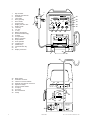
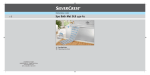
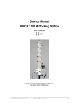
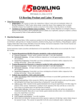
Drip chamber
External drop detector
Air detector
Tube guide
Door (opened)
Door handle
Stop flow lock
Display "infusion rate"
Display "total"
"100"-key
"10"-key
"1"-key
Battery discharged
Occlusion/bottle empty
ALARM
Line operation
Battery operation
Drop indicator
KVO-operation
"ON/OFF"-key
"MODE"-key
"START/STOP"-key
Air
Display "Pressure"
1
green stream VO-P
8
10
11
100
2
24
ml total
ml inf.
h. min
ml
h
12
10
MODE
19
ALAR M
ALARM
13
14
START
START
STOP
ST
OP
15
1
c
16
17
18
23
9
20
21
22
3
PVC
18-30°C
18-30°C
7
4
5
6
30
30
31
32
33
34
35
36
37
38
39
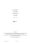
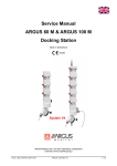
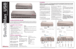
Bottle holder
Staff alert connector
Interface connector RS232
External drop detector connector
Spindle for clamp
Screw for bottle holder
Line plug
Line fuse
Ground terminal
Clamp
31
32
33
RS 232
35
34
38
39
AC:
Hz:
VA:
Fuse:
Prot.:
Battery:
36
2
30.09.2003
37
230V
50/60
9
63 mAT
IPX2
12V
ARGUS Medical AG
CH 3627 Heimberg
Volumetric pump
Typ: ARGUS 414
ID/Nr.
0120
14.131.A / A414e / Software 1.20
Table of contents
Page
1
Special key inputs and configurations
4
2
History and pump configurations printout
13
3
Fault finding
17
4
Replacement of parts
18
5
Safety standard check
23
Mechanical drawings
24
Wiring diagram
28
Bloc schematic
29
14.131.A / A414e / Software 1.20
30.09.2003
3
1
Special key inputs and configurations
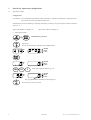
1.1
Special key inputs:
Configuration
CAUTION! The configuration possibilities mentioned below constitute a modification of the pump and
may only be carried out by authorized persons.
If the decimal points are flashing in a display, this display is ready to accept an input by means of the keys
"100, 10, 1".
Input of the address in display (2)
Input of the values in display (3)
a Interrogation mode
MODE
+
START
START
STOP
ST
OP
Hold both keys pressed
Important!
Do not release the keys "MODE" and "START/STOP"
ml
h
ml total
ml inf.
h. min
ml
h
ml total
ml inf.
h. min
START
START
STOP
ST
OP
100
10
1
Enter the requested address (eg. 52).
ml total
ml inf.
h. min
ml
h
The programmed data of address 52 are displayed
Press the key at least 2 seconds.
4
30.09.2003
14.131.A / A414e / Software 1.20
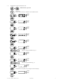
1.2
Configuration mode without PIN code
MODE
+
START
START
STOP
ST
OP
Hold both keys pressed
Important!
Do not release the keys "MODE" and "START/STOP"
ml
h
ml total
ml inf.
h. min
ml
h
ml total
ml inf.
h. min
ml
h
ml total
ml inf.
h. min
ml
h
ml total
ml inf.
h. min
ml
h
ml total
ml inf.
h. min
ml
h
ml total
ml inf.
h. min
START
START
STOP
ST
OP
MODE
START
START
STOP
ST
OP
MODE
START
START
STOP
ST
OP
100
00
1
10
Enter the requested address (eg. 5).
ml
h
ml total
ml inf.
h. min
ml
h
ml total
ml inf.
h. min
MODE
100
00
1
10
ml
h
START
START
STOP
ST
OP
Enter the requested data (eg. 1).
ml total
ml inf.
h. min
If the data are accepted, entry changes to the left display.
ml
h
14.131.A / A414e / Software 1.20
ml total
ml inf.
h. min
30.09.2003
5
1.3
Programming mode: first input of write protection (code)
IMPORTANT ! Remember to make a note of your code and keep it in a safe place.
Key
1.4
Display (8)
Display (9)
"prog"
1 "MODE" &
"START/STOP"
Keep both keys pressed before switching
the unit on.
"414"
2 "START/STOP"
Acknowledgement (write protection is inactive)
". . 0."
"
3 "MODE"
Switch over to display (9)
" 0"
". . . 0."
4 "START/STOP"
Acknowledgement
"Cod"
"- - - - "
5 "MODE"
Switch over to display (9)
"Cod"
"
0"
6 "START/STOP"
Acknowledgement
". . 0."
"
0"
7 "MODE"
Switch over to display (9)
" 0"
". . . 0."
8 "100;10;1"
Enter 1 to 4 digit code
" 0"
" C.C.C.C."
9 "START/STOP"
Acknowledgement (write protection is active)
Code is never visible
". . 0."
10 "ON/OFF"
End of programming mode
0"
"
1"
Programming mode with active write protection (code)
CAUTION! Only the code holder can carry out modifications when the write protection is active.
Key
1 "MODE" &
"START/STOP"
2
6
Description
Description
Keep both keys pressed before switching
the unit on.
"START/STOP" Acknowledgement (write protection is active)
Display (8)
Display (9)
"414"
"prog"
". . 0."
0"
1"
3 "MODE"
Switch over to display (9)
4 "START/STOP"
Acknowledgement
"Cod"
"- - - - "
5 "100;10;1"
Enter code
"Cod"
" X X X X"
6 "START/STOP"
Acknowledgement
". . 0."
7 "100;10;1"
Enter requested address
Programmed data appear in display (9)
"A.A.A."
"X X X X"
8 "MODE"
Switch over to display (9)
" A A A"
" X.X.X.X."
9 "100;10;1"
Enter requested data
"A A A"
" Y.Y.Y.Y."
10 "START/STOP"
Acknowledgement.If the data are accepted,
entry changes to display (8)
"A.A.A."
" Y Y Y Y"
11 "ON/OFF"
End of programming mode
30.09.2003
"
"
". . . 1."
"
1"
14.131.A / A414e / Software 1.20
1.5
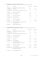
List of the interrogation- and configuration functions:
CAUTION! Before you make a new configuration or replace an EPROM or the mainboard make a note of
the programmed values. Afterwards you can re-enter the old not writeprotected values.
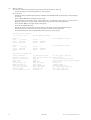
Address Write Default
(#)
prot. Value
Function
0
1
2
3
4
5
6
7
8
9
0 = No
1 = Yes
0 = No
0 = No
0 = No
0 = No
0 = No
0 = No
0 = No
1 = Yes
PIN code active
Run indication by running decimal point
Key "ON/OFF" only at STOP valid
Rate change only at STOP valid
Key "STOP" delayed (time at #361)
2nd entry of rate (#3=1), rate calculation disabled.
Static alarm (staff alerting system)
Display elapsed time in run mode (#8=0)
Select remaining time (#7=1)
Alternative time input (10h, 1h, 1/4h)
10
11
12
13
14
15
16
17
18
19
0 = No
1 = Yes
0 = No
0 = No
0 = No
0 = No
0 = No
1 = Yes
0 = No
1 = Yes
Operation without drop detector
Recall "ml/h" (rate) at next power on
Recall "ml total" (end volume) at next power on
Recall "ml inf." (volume inf.) at next power on
SBS Step By Step function
Display VTBI (Volume To Be Infused)
Display "SEt -X-"’ if only 1 set enabled
KVO (KOR), mode see #60
Drop alarm only if bottle is empty (#10=0)
Buzzer at start
20
21
22
23
24
25
26
27
28
29
0 = No
0 = No
0 = No
1 = Yes
1 = Yes
0 = No
0 = No
0 = No
0 = No
0 = No
Menu "CLr" (clear "ml inf.") (#15=0)
Menu "uOP" (Micro operation)
Menu "trA" (transport) (#10=0 and #18=0)
Menu "PrL" (pressure alarm limit)
Menu "CAP" (battery capacity)
Menu "SEt Fill"
Menu "InF" ("ml inf." since last power on)
Menu "dLo" (data-lock)
Menu "Stb" (stand-by)
Menu "MEd" (medication number)
****
****
****
****
****
****
****
****
****
****
30
31
32
33
34
35
36
37
38
39
0 = No
0 = No
0 = No
0 = No
0 = No
0 = No
0 = No
0 = No
0 = No
0 = No
Menu "tM " (timer alarm)
****
Menu "boL" (release bolus)
Menu "boLr" (bolus rate) (#32=1)
Menu "tot" (bolus total) (#32=1)
****
****
****
40
41
42
43
44
45
46
47
48
49
0 = No
0 = No
0 = No
0 = No
1 = Yes
1 = Yes
0 = No
0 = No
1 = Yes
0 = No
****
Bolus application automatic (#32=1 and #34=1)
Demo mode (all menus enabled)
Clear "ml/h" after infusion completed
Clear "ml total" after infusion completed (#41=1)
Air volume accumulated (1ml over 0.5 hrs)
Automatic pressure release after occlusion
Pressure display 20/40/60/80/100% (Bargraph ON)
Bargraph with indicator (25% steps, #45=1)
Standby- and battery prealarm low volume
Flashing numeric display at alarm
Alarm acknowledge only with key "MODE"
14.131.A / A414e / Software 1.20
30.09.2003
****
7
Address Write Default
(#)
prot. Value
8
Function
50
51
52
53
54
55
56
57
58
59
0 = No
1 = Yes
1 = Yes
0 = No
0 = No
0 = No
0 = No
0 = No
0 = No
0 = No
Start with >= 1bar allowed
Start without infusion set
High resolution if calculated rate <100 ml/h
Micro mode after power on as default (Clear = 0.0 ml/h)
60
61
62
63
64
65
66
67
68
69
0 = No
0 = No
0 = No
0 = No
0 = No
0 = No
0 = No
0 = No
0 = No
0 = No
KVO only after infusion completed
100
101
102
103
104
105
106
107
108
109
0 = No
1 = Yes
0 = No
0 = No
0 = No
0 = No
0 = No
0 = No
0 = No
0 = No
200
201
202
203
204
205
206
207
208
209
0 = No
0 = No
0 = No
0 = No
0 = No
0 = No
0 = No
0 = No
0 = No
0 = No
210
211
212
213
214
215
216
217
218
219
0 = No
0 = No
0 = No
0 = No
0 = No
0 = No
0 = No
0 = No
0 = No
0 = No
Clear and continue (#15=0)
Set 1 enabled
Set 2 enabled (Pressure sensor and volume calibration requested)
Set 3 enabled (Pressure sensor and volume calibration requested)
Set 4 enabled (Pressure sensor and volume calibration requested)
Set 1 definition
30.09.2003
14.131.A / A414e / Software 1.20
Address Write Default
(#)
prot. Value
220
221
222
223
224
225
226
227
228
229
0 = No
0 = No
0 = No
0 = No
0 = No
0 = No
0 = No
0 = No
0 = No
0 = No
230
231
232
233
234
235
236
237
238
239
0 = No
0 = No
0 = No
0 = No
0 = No
0 = No
0 = No
0 = No
0 = No
0 = No
240
241
242
243
244
245
246
247
248
249
0 = No
0 = No
0 = No
0 = No
0 = No
0 = No
0 = No
0 = No
0 = No
0 = No
250
251
252
253
254
255
256
257
258
259
0 = No
0 = No
0 = No
0 = No
0 = No
0 = No
0 = No
0 = No
0 = No
0 = No
260
261
262
263
264
265
266
267
268
269
0 = No
0 = No
0 = No
0 = No
0 = No
0 = No
0 = No
0 = No
0 = No
0 = No
Function
Set 2 definition
Set 3 definition
Set 4 definition
14.131.A / A414e / Software 1.20
30.09.2003
9
Address Write Default
(#)
prot. Value
270
271
272
273
274
275
276
277
278
279
0 = No
0 = No
0 = No
0 = No
0 = No
0 = No
0 = No
0 = No
0 = No
0 = No
300
301
302
303
304
305
306
307
308
309
0
0
0
0
0
0
0
0
0
0
330
331
332
333
334
335
336
337
338
339
10
IV set -1IV set -2-
320
321
322
323
324
325
326
327
328
329
IV set -3-
310
311
312
313
314
315
316
317
318
319
X
X
X
X
Function
Set 4 definition
Infused sum in ml (xxxxyyyy)
Infused sum in ml (xxxxyyyy)
Operating time in min (xxxxyyyy)
Operating time in min (xxxxyyyy)
999
999
999
10
0
4
7
250
20
1000
Max. rate in ml/h (1...999 ml/h)
Prime rate in ml/h (1...999 ml/h)
Max. bolus rate in ml/h (1...999 ml/h)
Max. bolus total in ml (1...99 ml)
999
999
999
10
0
4
7
250
20
1000
Max. rate in ml/h (1...999 ml/h)
Prime rate in ml/h (1...999 ml/h)
Max. bolus rate in ml/h (1...999 ml/h)
Max. bolus total in ml (1...99 ml)
999
999
999
10
0
4
7
250
20
1000
Max. rate in ml/h (1...999 ml/h)
Prime rate in ml/h (1...999 ml/h)
Max. bolus rate in ml/h (1...999 ml/h)
Max. bolus total in ml (1...99 ml)
Pressure limit "PrL" default value micro mode
Pressure limit "PrL" default value
Airbubble size (50...1000 µl)
Drop-rate window centre in drops/ml (10...65)
Correction (850...1150) ((actual/nominal)*1000)
Pressure limit "PrL" default value micro mode
Pressure limit "PrL" default value
Airbubble size (50...1000 µl)
Drop-rate window centre in drops/ml (10...65)
Correction (850...1150) ((actual/nominal)*1000)
Pressure limit "PrL" default value micro mode
Pressure limit "PrL" default value
Airbubble size (50...1000 µl)
Drop-rate window centre in drops/ml (10...65)
Correction (850...1150) ((actual/nominal)*1000)
30.09.2003
[xxxx . . . . ml]
[. . . . yyyy ml]
[xxxx . . . . min]
[. . . . yyyy min]
(1..10 * 100 mbar)
(1..10 * 100 mbar)
(1..10 * 100 mbar)
(1..10 * 100 mbar)
(1..10 * 100 mbar)
(1..10 * 100 mbar)
14.131.A / A414e / Software 1.20
340
341
342
343
344
345
346
347
348
349
IV set -4-
Address Write Default
(#)
prot. Value
999
999
999
10
0
4
7
250
20
1000
360
361
362
363
364
365
366
367
368
369
0
500
3
10
0
0
0
0
270
5
370
371
372
373
374
375
376
377
378
379
0
0
0
0
0
0
0
0
0
0
380
381
382
383
384
385
386
387
388
389
390
391
392
393
394
395
396
397
398
399
X
X
X
X
X
X
X
X
X
X
X
X
X
Function
Max. rate in ml/h (1...999 ml/h)
Prime rate in ml/h (1...999 ml/h)
Max. bolus rate in ml/h (1...999 ml/h)
Max. bolus total in ml (1...99 ml)
Pressure limit "PrL" default value micro mode
Pressure limit "PrL" default value
Airbubble size (50...1000 µl)
Drop-rate window centre in drops/ml (10...65)
Correction (850...1150) ((actual/nominal)*1000)
(1..10 * 100 mbar)
(1..10 * 100 mbar)
Key "ON/OFF" delay (0...3000 msec), (additional key "STOP"] if #4=1)
Display brightness (1...3)
Buzzer alarm volume (5...10)
Battery discharge time incl. 15 min prealarm (45...615 min)
Automatic menu fall back delay time
(5...30 s)
Clock seconds
Clock minutes
Clock hours
(0...59)
(0...59)
(0...23)
Clock days
Clock months
Clock years
(1...31)
(1...12)
(2000...2099)
Last failure number (F-XX)
Last infusion rate at failure
2. last failure number (F-XX)
2. last infusion rate at failure
3. last failure number (F-XX)
3. last infusion rate at failure
4. last failure number (F-XX)
4. last infusion rate at failure
5. last failure number (F-XX)
5. last infusion rate at failure
0
0
0
0
0
0
0
0
0
414
Last service date (yyww, year and week)
2. last service date
3. last service date
Service interval in months (1..24, 0 = disabled)
Service interval in hours (1..9999, 0 = disabled)
Own address for SCI (0=no address, or 1...127)
Inventory-no. of the pump (xxxx yyyy)
Inventory-no. of the pump (xxxx yyyy)
[xxxx . . . .]
[ . . . . yyyy]
Data xxxx -> clears protection key
14.131.A / A414e / Software 1.20
30.09.2003
11
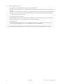
1.6
Special configuration options
- Configuration of a reminder alarm for the safety standard check:
First the service interval has to be configured either in months or in hours of operation, or both (addresses
393, 394).
Next the last service date has to be entered on address 390. Any value higher than 0 entered at the adresses
393 and/or 394 will release the reminder alarm after the set service interval has elapsed (check also the
correct settings of the internal clock).
- PC configuration tool "AConfig":
With this additional software the pump may be configured from a PC over the serial port. This software
may be available from your local distributor or our service department.
- IV-set definition:
Allows the individual calibration of up to 4 dedicated IV-sets over the full infusion rate range. Please
contact your local distributor or our service department for further information.
After changing the configuration a function check and a control measurement has to be made!
12
30.09.2003
14.131.A / A414e / Software 1.20
2
History and pump configuration printout
2.1
Connecting of the ARGUS414 to the serial interface
Caution: The infusion pump must be disconnected from the patient before any connection
over the serial interface can be done.
A connection of the ARGUS414 to a computer is useful to the read the actual configuration or history of the
pump. Even a simple monitoring of the pump can be done over the serial interface RS-232.
The connection of the infusion pump with your computer over the interface can be done by connecting the
interface cable and adapter (part 12.011 and part 12.012) and the following steps:
-
Connect the RS-232 interface cable to outlet (32) of the infusion pump and to the serial port of your PC.
Note in which port (COM1 or COM2) you have pluged in.
Start your terminal program on your computer. A simple terminal program, e.g. "Hyper Terminal" is
included in every MS-Windows 9x and Windows NT systems, but must be installed first if necessary.
Be sure that you have selected the right serial port (COM1 or COM2) and set the following communication parameters:
Bits per second:
Data bits:
Parity:
Stop bits:
Protocol:
2.2
4800 Baud
8 bits
None
1 bit
None
Go to the next step in one of the further chapters, depending on your intention.
Configuration printout
- Switch the pump on while keeping the keys "MODE" and "START/STOP" pressed and go in the configuration mode.
- Select address 399 on the left hand display.
- Start capturing text received over the serial interface, e.g. by selecting "capturing text..." in the menu of
the Hyper terminal. A text file which contains the actual configuration printout will now be generated.
- Enter the data 3456 on the right display of the pump.
- Press the "START/STOP" key.
- The pump will now transfer the actual configuration of the pump in the format mentioned below.
- Stop the capturing of the text received; this will also close the text file generated.
- The generated text file can be opened and printed out by any text program.
Pump configuration printout (sample)
/***** Configuration profile *****/
Pump type
Inventory number
Software release
Infused sum
Operating time
Last service date
00=0
01=1
02=0
03=0
etc.
50=0
51=0
52=0
53=1
14.131.A / A414e / Software 1.20
100=0
101=0
102=0
103=1
:
:
:
:
:
:
Wed 19-Jan-2002 11:29:55
ARGUS414
0000 0000
V1.00 (000719-4061)
678ml
5h32min
2000 week 12
300=0
301=0
302=0
303=0
320=0400
321=0000
322=0000
323=0000
30.09.2003
340=0000
341=0000
342=0000
343=0000
360=0000
361=0000
362=0000
363=0000
380=0000
381=0000
382=0000
383=0000
13
2.3
History printout
The transfer of the last events made on the pump can be done either by this way:
- Switch the pump on while keeping the key "100" pressed.
Or by this way:
- Switch the pump on while keeping the keys "MODE" and "START/STOP" pressed and go in the configuration mode.
- Select address 399 on the left display of the pump.
- Start capturing text received over the serial interface, e.g. by selecting "capturing text..." in the menu of
the Hyper terminal. A text file which contains the history printout will now be generated.
- Enter the data 4567 on the right display of the pump.
- Press the "START/STOP" key.
- The pump will now transfer the last events made on the pump in the format mentioned below.
- Stop the capturing of the text received; this will also close the text file generated.
- The generated text file can be opened and printed out by any text program.
History printout (sample)
/***** History *****/
Mon 28-Aug-2000 08:42:44
Pump off
Rate
= 123.0ml/h
Total = 0050.0ml
Infsum = 0054.0ml
IV-Set = 3
PrLimit = 0500mbar
Status = 0x0000
Pump on
Rate
= 010.0ml/h
Total = 0050.0ml
Infsum = 0009.0ml
etc.
Mon 28-Aug-2000 11:54:38
Mon 28-Aug-2000 15:01:58
IV-Set = 3
PrLimit = 0500mbar
Status = 0x0000
The possible messages are:
Battery defective
Battery low prealarm
Battery low, pump stop
Bolus start
Bolus stop
External power off
External power on
Bolus total reached
Occlusion, pump stop
PrLimit change
PC configuration failure
14
PC configuration done
Pump has detected failure
Pump off
Pump on
Pump start
Pump stop (KVO)
Rate change
Enter setup mode
Exit setup mode
Transport off
Transport on
30.09.2003
Too many drops, pump stop
Inf-set change
Timer alarm, pump stop (KVO)
Total volume reached, pump stop (KVO)
Datalock off
Datalock on
Infsum cleared
No drops, pump stop
Not enough drops, pump stop
Door open, pump stop
Air bubble, pump stop
14.131.A / A414e / Software 1.20
2.4
Monitoring of the ARGUS414
Caution: The monitoring of the infusion pump ARGUS414 over the serial interface of a PC is only for
demonstration purposes; any connection with patients has not been tested under the
conditions of EN 60601-1 and are not allowed.
-
Switch the pump on with an inserted filled infusion set.
Enter one of the following command directly in your terminal window or transmit the corresponding
ASCII
code over your own monitoring program. A short sample of a monitoring session is mentioned at the end
of this chapter.
Command
Keystrokes in terminal
ASCII code
Description
ENQ
SO
Ctrl+E
Ctrl+N
05H
0EH
Request status (see format below)
Sets pump in remote mode
STX
‘data‘
ETX
Ctrl+B
Data
Ctrl+C
02H
03H
Start of data entry (see format below)*
Data*
End of data entry*
DC2
DC4
SI
ACK
FS
BEL
CAN
Ctrl+R
Ctrl+T
Ctrl+O
Ctrl+F
Ctrl+\
Ctrl+G
Ctrl+X
12H
14H
0FH
06H
1CH
07H
18H
Start infusion*
Stop infusion*
Sets pump in local mode
Alarm suppression (2min)*
Enables/disables KVO*
Toggle "Buzzer at start mode"*
No start tests at next start*
ESC
Ctrl+[
1BH
"addr"
-
0-127
Next character following ESC ("Ctrl+[") will select
the
pump with address ‚"addr", if more than one
is connected to the serial interface
Address (must be the same as in the pump
configuration on address 395)*
* Only valid in remote mode
Total 1E0
Total 1E1
Total 1E2
Total 1E3
Rate 1E-1
Rate 1E0
Rate 1E1
STX 0 1 2 0 0 2 0 0 ETX
Rate 1E2
Format of "data" entry:
Format of "status", which will be returned by the pump after typing "Ctrl+E" in the terminal:
14.131.A / A414e / Software 1.20
30.09.2003
Statusbyte-5
Statusbyte-4
Statusbyte-3
Statusbyte-2
Statusbyte-1
Medicament 1E0
Medicament 1E1
PrL 1E0
PrL 1E1
PrL 1E2
PrL 1E3
Infused sum 1E0
Infused sum 1E1
Infused sum 1E2
Infused sum 1E3
Total 1E0
Total 1E1
Total 1E2
Total 1E3
Rate 1E-1
Rate 1E0
Rate 1E1
Rate 1E2
STX 0 1 2 0 0 2 0 0 0 0 0 1 0 7 0 0 0 0 A B C D E ETX
15
Airbubble, pump stop
Bottle empty, pump stop
Reserved
Reserved
Reserved
Occlusion, pump stop
Always high
Parity
Battery defective
Battery low, pump stop
Battery low prealarm
Battery active
Reserved
P 1 X X X X X X
Pump type (0 = A414)
P 1 X X X X X X
Always high
Format statusbyte-2:
Parity
Format statusbyte-1:
Standby alarm active
Timer alarm, pump stop (KVO)
Data lock active
Bolus active
Reserved
Total volume reached, pump stop (KVO)
Format statusbyte-5:
Always high
Parity
KVO active
Pump stop (KVO)
Door open
Global Alarm
Reserved
P 1 X X X X X X
Remote mode active
P 1 X X X X X X
Always high
Format statusbyte-4:
Parity
Format statusbyte-3:
Bargraph-LED lower
Bargraph-LED lower+1
Bargraph-LED lower+2
Bargraph-LED lower+3
Bargraph-LED upper
Pressure indicator (adress 46)
Always high
Parity
P 1 X X X X X X
A sample of a monitoring session:
- Switch the pump on with an inserted filled infusion set.
- Type "Ctrl+N" to set the pump in remote mode.
- Type "Ctrl+B", then "01200200" and then "Ctrl+C" which sets the rate to 12.0 ml/h and an infusion total of
200 ml. The rate should now be shown in the left display of the pump.
- Type "Ctrl+R" to start the infusion.
- Type "Ctrl+T" to stop the infusion.
16
30.09.2003
14.131.A / A414e / Software 1.20
3
Fault finding
The fault code in case of a failure is displayed by pressing "MODE" key (21). (F-XX) appears in display (9),
and the source of the failure is listed in the table below:
Error
Error reason
Assembly group
F-21...22
F-23...24
F-25
F-26
F-27
F-28
F-29
F-31
F-32
F-33
F-41
F-42
F-43
F-44...45
F-46
F-47
F-48
F-49
F-50
F-51...56
ROM test
RAM test
CPU test
Invalid function menu
EEPROM data invalid
RTC (real time clock) data invalid
Stepper motor power test
1.2 Volt supply out of range
5 Volt supply out of range
30 Volt supply out of range
Pressure sensor test failed
Air detector test failed
Air bubble size invalid
Address invalid for EEPROM
Frequency from µC or RTC out of range
Displayboard not present
Key(s) too long active
Set correction invalid
Pressure monitor
Rotation control
F-57...59
Volume control
Mainboard
Mainboard
Mainboard
Mainboard
Mainboard
Mainboard
Mainboard
Mainboard
Mainboard
Pressure sensor or mainboard
Air detector or mainboard
Mainboard
Mainboard
Mainboard
Displayboard
Mainboard
Mainboard or pressure sensor
- Mainboard
- Hallboard
- Motor
- Clutch
Mainboard
Exceptionally a fault code may appear, which is not included in this list. In this case we recommend to
change the main board.
14.131.A / A414e / Software 1.20
30.09.2003
17
4
Replacement of parts
4.1
Disassembly of the pump
NOTE: The exploded views in the appendix show the individual mounting steps.
CAUTION!
Switch the unit off and disconnect the mains cable from the power outlet before opening the housing. The
antistatic protection have to be strictly adhered to when the ARGUS infusion pump is disassembled (the use
of an antistatic table mat and a grounded clip are recommended, for example).
a Disassembly of the hood:
Remove the four screws on the side and on the rear wall, lift hood up and disconnect the plug-type
connector of the drop barrier.
b Disassembly of the main printed board assembly:
Disconnect the plug-type connector of the main printed board assembly and unscrew the two lateral
attachment screws. Please refer to the wiring diagram in the appendix.
c Disassembly of the front panel:
Use a ball-headed hexagon screwdriver to unscrew the two attachment screws from the rear and remove
the front panel. This special screwdriver can be obtained from the service department on request.
d Disassembly of the pump unit:
By unscrewing the four attachment screws, the whole pump unit can be removed from the front panel.
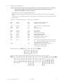
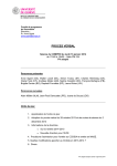
e Remove the pump door:
The pump door can be remove without any tools by pulling it out in the
direction of the arrow according to the drawing. For the dismounting and the
mounting the opening angle from 30 to 45° has to be kept.
4.2
30-45°
Replacement of the EPROM or the display board
a Software updates may reset automatically the default values in the EEPROM. You are requested to write
down the actual contents of the addresses before you replace the EPROM or the display board. Afterwards
you have to re-enter these values in the program mode. If a write protection code has been used before, the
same code has to be programmed again.
b A pressure sensor calibrating is necessary when replacing the pressure sensor, a pressure sensor
calibration and a volume calibration are necessary when replacing the EPROM or the display board. Be
careful and carry out the described instructions step by step.
18
30.09.2003
14.131.A / A414e / Software 1.20
4.3
Pressure sensor calibration
1 Go to the program mode (without IV-administration set).
2 Enter in address 399 the value 1234.
3 Press the key "START/STOP"
The display shows e.g. [Set] [-2- ]. Choose the IV set (no. 1 to 4) by pressing the key [1].
4 Press the key "START/STOP" (The pump mechanic runs with a rate of ca. 200 ml/h).
The display shows [CAL.] [door]. By pressing the key "1" it is possible to show the stored value in mV
in the display.
5 Press the key "START/STOP". The offset voltage, without IV-set, will be stored.
The stored value will be acknowledged by a sound.
6 Press the key "MODE".
The display shows [CAL.] [0bAr]. By pressing the key "1" it is possible to show the stored value in mV
in the display.
7 Install an used (milled) IV-administration set (Open the roller clamp).
8 Start the pressure build-up by occluding the tube on the patient side to control the mechanical pressure
limit.
Minimum 1.2 bar has to be reached for a successful calibration.
9 Gradually decrease the pressure by removing the occlusion.
10 Wait ca. 30 sec., then activate the key "START/STOP". The reference value for sensitivity calculation will
be stored. The stored value will be acknowledged by a sound.
11 Press the key "MODE".
The display shows [CAL.] [1bAr]. By pressing the key "1" it is possible to show the stored value in mV
in the display.
12 Start the pressure build-up again, wait until the manometer shows 1 bar, then activate the
key "START/STOP". The absolute value at 1 bar will be stored. The stored value will be acknowledged
by a sound.
13 Gradually decrease the pressure.
14 Turn the pump off- and on again.
15 Select the rate at 500 ml/h.
16 Press the key "START/STOP".
17 Start the pressure build-up to control the electronic pressure limit.
18 The alarm must be activated at ca. 700 mbar ± 100 mbar if the default value = "7".
If the result is not satisfactory repeat the sensor calibration.
19 Switch the pump off.
14.131.A / A414e / Software 1.20
30.09.2003
19
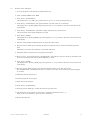
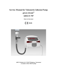
4.4
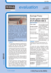
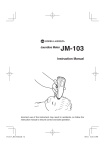
Pressure sensor signal
Sensor signal
mVolt
If the value meassured by the sensor after put in
a tube without pressure is higher then the stored value
for 1 bar, the pump cannot be started.
5000
Value
sensitivity
4000
Auto
adjust
System limit 4700 mV
Value 1 bar
3000
1000
0
Value
no tube
2000
Pressure
0 bar
Door open
without a tube
20
1,0 bar
Door closed
with a tube,
pressure 1,0 bar
Door closed
with a tube,
no pressure
30.09.2003
14.131.A / A414e / Software 1.20
4.5
Volume calibration general
1 Go into the program mode.
2 Decide which IV set should be calibrate and check its release address.
- address 101 for IV set no. -1- address 102 for IV set no. -2- address 103 for IV set no. -3- address 104 for IV set no. -4Set the correction value in one of the following address to 1000:
- address 319 for IV set no. -1- address 329 for IV set no. -2- address 339 for IV set no. -3- address 349 for IV set no. -4Switch the pump off and on.
3 Select the IV set you like to calibrate and make the following pump settings (for warm up the peristaltic
system): Rate = 999 ml/h; volume "total" = 10 ml
Start the pump by pressing "START/STOP" once. Switch the pump off and on again after the volume
"total" is reached.
4 The next pump settings are:
Rate = 100 ml/h; volume "total" = 25 ml
Start the pump by pressing "START/STOP" once. Switch the pump off immediately after the volume
"total" is reached, the net weight result must be 25 g +/-5%.
5 Calculate the correction factor with the equation:
Correction factor = (measured volume / preset volume) * 1000
6 Go into the program mode and select address for the correction value (see point 1)
Press "MODE" to enter the correction factor in the right hand display.
Press "START/STOP"] to acknowledge the correction factor.
Switch the pump off.
7 Make a control measurement with the same settings as mentioned in point 4, using the IV-set for which
the correction factor has been changed. Perform an occlusion pressure check (see chapter "Pressure
sensor calibrating", point 15-19) to verify the pressure alarm level.
14.131.A / A414e / Software 1.20
30.09.2003
21
4.6
Volume calibration by the integrated program
1 Go to the program mode.
2 Enter in address 399 the value 123.
3 Press the key "START/STOP".
The display shows e.g. [Set ] [-2- ]. Choose the IV set (no. 1 to 4) by pressing the key [1].
4 Press the key "START/STOP".
The display shows [bAL.] [tArA]. The right hand display is flashing.
The pump delivers a volume of 5 ml by a rate of 250 ml/h to warm up the tube.
5 The display shows [bAL.] [tArA].
Re-zero the balance.
6 Press the key "START/STOP".
The display shows [tM ] [ xxx].
The pump delivers a volume of 15 ml by a rate of 250 ml/h.
7 The display shows [bAL.] [12.75].
Enter the value of the balance into the pump e.g. 14.65.
8 Press the key "START/STOP".
The display shows e.g. [Cor.] [ 977 ].
9 Press the key "START/STOP".
The display shows e.g. [Set] [-2- ] and an acknowledgement sound occurs.
The correction factor has been stored in the address of the choosed IV set (see point 3).
10 Switch the pump off.
11 Make a control measurement with the same settings as mentioned in point 4 using the IV-set for which the
correction factor has been changed. Perform an occlusion pressure check (see chapter "Pressure sensor
calibrating", point 15-19) to verify the pressure alarm level.
4.7
Calibration of the battery capacity
Each battery is subject to a chemical process with a slowly decreasing running time. After many charge and
discharge cycles the battery may not have the capacity which provided the running time shown in the menu
"CAP".
To adjust the running time of the used battery please follow the steps mentioned below:
-
-
22
Go in the configuration mode of the pump.
Select address "368" in the left display.
Enter the data "615" in the right display and press the "START/STOP" key to accept the data. This will set
the battery discharge time to the maximum of >10 hours.
Switch the pump off.
Be sure you have unplugged the line connection.
Switch the pump on normally and let the pump running in battery mode until its self switching off.
Load the battery for more than 16 hours by plug in the line.
Switch on the pump and start an infusion with a rate of 60ml/h. The infused sum at this rate is now equal to
battery operating time in minutes.
Leave the pump running until the pump its self switching off again.
Switch the pump on while keeping the key "1" pressed. The right display now shows the capacity of the
battery in minutes. Multiply this time x 0.8 and enter the result on address "368" in the configuration mode.
This time defined from now on the running time of the pump including a 15 minutes pre-alarm (only after a
full charge).
If this time is less than 4 hrs, you should replace the battery (part 10.016). If the specific time > 4hrs is not
necessary, the battery has to be changed only if the time less than 3hrs, with respect to environ pollution.
30.09.2003
14.131.A / A414e / Software 1.20
5
Safety standard check
Safety standard check
ARGUS 200
ARGUS 400
ARGUS 404
Serial-no: ........................
ARGUS 414
O
O
O
O
ARGUS Medical AG
Hospital/Dept./Customer: ...................................................................................................................................................
................................................................................................................................................................................................
The safety standard check has to be performed at least every 24 months or after 10000 hours of operation.
The check has to be done in accordance to the operation- and service manuals.
1
Visual check for damage, cleanness and completeness:
2
Test the function of the stop flow lever:
3
Keep key "START" (ARGUS 200/400/404) or
"MODE" (ARGUS 414) pressed while switching on
the pump.
- Display shows the software release:
- Display of 2, 4, 7, F., ml total, ml inf., h.min
- Test of the red alarm LEDs:
Pressure display, air, battery, drops, ALARM
- Test of the green operation LEDs:
Line, battery, drops, KVO
4
Place a filled tube in the air detector:
- LED air alarm disappeared
5
Set rate to 111 ml/h, press "START/STOP"
(without drop detector):
- After 12 sec. the acoustical alarm and
LED drop-alarm + LED ALARM released
6
Press key "MODE":
- Acoustical alarm switches off
7
Simulate drops manually:
- LED drops (green) lights up
8
Check of the occlusion-alarm-pressure:
- See Service manual "Replacement of parts"
Infusion set:
Codan .....
Pressure increase to ≥1.1 bar?
Test of the occlusion-alarm-pressure
9
Check of the pump accuracy:
Rate: 250 ml/h
- Housing, labels, accessories, connectors,
power cable, etc.
V ..................
Braun .....
Other ...........................
Preset level: ......... mbar
Measured: ......... mbar
- See service manual "Replacement of parts"
Preset volume: 25 ml
Measured volume: ............ ml
10 Test the pump at max. rate (999 ml/h):
- Running smooth?
11 Battery check by setting the rate to 60 ml/h,
disconnect the line and start the pump:
- Green LED battery light?
- Battery prealarm after typ. 4 hrs?
(Red LED battery alarm + acoustical alarm)
- Battery alarm 15 min. after prealarm
(Red LED battery alarm + ALARM + alarm acoustically)
- After 6 min. the pump switches off
Running time: ............. min
(If the specified typical 4hrs of operation are not
required, the battery has to be changed only
if the time is <3 hrs, due to environmental pollution)
12 Charge the battery min. 16 hrs.
13 Check the external connections:
- Staff alerting system
- External drop detector
- Computer interface RS232
14 Electrical test according to EN60601-1
(all measurements made with a power cable 2,5 m)
- Measurements attached
The pump has passed the safety standard check and is safe for use.
Date: ...........................
14.131.A / A414e / Software 1.20
Name: ...............................
Signature: ....................................
30.09.2003
23
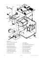
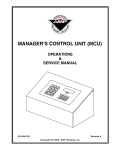
10.076
11.005
11.002
11.120
11.061
11.018
10.053
10.016
12.016
11.105
12.001
12.008
10.006
10.008
12.002
10.084
Casing A414
24
10.006 Air detector with O-sealing
11.105 Sealing
10.008 Transformer 230V
11.061 Clamp holder
10.016 Battery 12V/1,2Ah
11.127 Identification plate ARGUS 414
10.053 Clamp with screws
11.120 Fixing screw M5x20 black
10.076 Main board ARGUS 414
12.001 Equipotential plug
10.084 Casing with rubber foot
12.007 Cable staff alert (opt.)
11.002 Spindle for pole clamp
12.008 Mains plug with filter
11.005 Bottle holder 450mm
12.011 RS 232 cable
10.084 Casing with rubber foot
12.012 RS 232 adapter
11.018 Battery holder
12.016 Srew for bottle holder
30.09.2003
14.131.A / A414e / Software 1.20
11.128
11.081
10.036
10.077
11.019
11.021
Front A414
10.036
10.077
11.019
11.021
11.081
11.128
14.131.A / A414e / Software 1.20
30.09.2003
Display PC-board
Pump unit without door
Spring (Front-housing)
Cable assy 26pol
Front PVC
Frontpanel A414
25
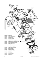
10.081
10.037
10.080
11.038
11.037
11.010
11.039
10.083
12.006
11.101
10.002
11.100
11.031
10.013
10.009
12.006
11.038
11.129
Pump unit A414
10.002
Camshaft
10.009
Clutch assembly kit
10.013
Stepper motor
10.037
Pressure sensor
10.078
Hall PC-board
10.080
Stop flow lever with spring
10.081
Stop latch with spring
10.082
Side wall motor with motor plate
10.083
Pump unit holder with axle
11.003
Pulley-drive 32 XL
11.004
Pulley-drive 11XL
11.010
Slider
11.031
Axle (door hinges)
11.034
Support bearing
11.036
Cable / bearing holder
11.037
Bearing holder
11.038
Distance holder
11.039
Side wall with bolt
11.100
Housing for sliders
11.101
Sealing
11.129
PCB-holder
12.003
Drive belt 90XL
12.006
Ballbearing
26
11.036
10.078
10.082
12.003
11.004
11.003
11.034
30.09.2003
14.131.A / A414e / Software 1.20
10.089
10.056
11.111
11.008-1 (d=0,7 D=6,0 l=15,0 n=7,5)
10.079
11.017
Cover and Door A414
10.056
10.050
10.079
10.089
11.008-1
11.017
11.111
14.131.A / A414e / Software 1.20
Cover with magnet
Door complet
Door with handle
External drop detector 01
Pressure spring no. 1
Door cover
Counter plate
30.09.2003
27
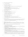
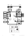
Serial
Interface
RS 232
Nurse-call
Alarm
4
1
1
External
Drop-Detector
8
1
Serial
Interface Nurse-call
Alarm
RS 232
External
Drop-Detector
Internal
Drop-Detector
4
X9
X7
X5
X8
X12
External
Buzzer
X13
X2
AC Input
Trafo
X3
Batt.
12 V DC
Air Bubble
Detector
External
15 V DC
X6
X4
Hall
Door + Wheel
X1
µC
Buzzer
Pressure
Sensor
Stepper
Motor
X11
EPROM
X10
Wiring diagram
28
30.09.2003
14.131.A / A414e / Software 1.20
14.131.A / A414e / Software 1.20
30.09.2003
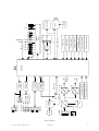
Ext. DC
NiCd-Batt.
12V
DC
DC
DC
Battery voltage control
Line voltage control
DC
DC
+ 5V
(Logic)
+ 30V
(Motor +
Buzzer)
2
I C
EPROM
Display
Driver
External drop detector
Internal drop detector
Air bubble detector
Hall Door + Wheel
Pressure sensor
+5V Control
+30V Control
SQW-Frequency
Latch
1
AC
KVO
Mode
AC Main
On/Off
100
Power test
Reset +
Watchdog
Isolation
Relay
Driver
Controller
10
Motor
Motor
Driver
Alarm
Relay
Buzzer
Driver
Start/Stop
RS-232
Nurse-call
Ext. Buzzer
h. min
ml inf.
ml total
Pressure
Bloc schematic
29
Li-Batt.
3 Volt
RTC
EEPROM
ALARM
Alarm