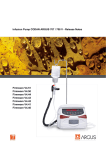
1
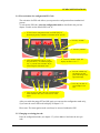
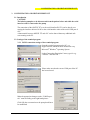
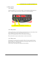
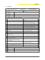
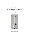
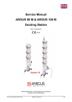
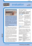
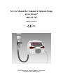
Service Manual for Volumetric Infusion Pump green stream® ARGUS 707 Made in Switzerland 0120 ARGUS Medical AG, CH-3627 Heimberg / Switzerland (A member of the CODAN group) INTRODUCTION Table of contents 1. INTRODUCTION........................................................................................................................................................ 3 1.1. General ................................................................................................................................................ 3 2. PUMP CONFIGURATIONS...................................................................................................................................... 3 2.1. General ................................................................................................................................................ 3 2.2. Interrogation mode .............................................................................................................................. 4 2.3. Configuration mode............................................................................................................................. 5 2.4. First activation of a configuration PIN Code ...................................................................................... 7 2.5. Changing an existing pin code ............................................................................................................ 7 2.6. Address list of the pump configuration ............................................................................................... 8 2.7. Special configuration options.............................................................................................................10 3. CONFIGURATION AND HISTORY PRINTOUT............................................................................................... 11 3.1. Introduction ........................................................................................................................................11 3.2. Settings of the terminal program ........................................................................................................11 3.3. Configuration printout........................................................................................................................12 3.4. History printout ..................................................................................................................................14 4. SOFTWARE UPDATES ........................................................................................................................................... 16 4.1. General ...............................................................................................................................................16 4.2. Requirements for a software update ...................................................................................................16 4.3. Safety aspects .....................................................................................................................................16 5. MAINTENANCE ....................................................................................................................................................... 17 5.1. General ...............................................................................................................................................17 5.2. Recalibration ......................................................................................................................................17 5.3. Pressure calibration ............................................................................................................................17 5.4. Pressure control measurement............................................................................................................23 5.5. Volume calibration .............................................................................................................................24 5.6. Pump specifications............................................................................................................................25 5.7. Fault codes..........................................................................................................................................26 6. REPLACEMENT OF PARTS.................................................................................................................................. 27 6.1. General ...............................................................................................................................................27 6.2. Disassembling of the ARGUS 707.....................................................................................................27 6.3. Replacements of parts ........................................................................................................................31 6.4. Spare parts ..........................................................................................................................................32 7. SAFETY STANDARD CHECK............................................................................................................................... 36 8. WIRING DIAGRAMM ............................................................................................................................................. 37 9. BLOC SCHEMATIC................................................................................................................................................. 37 10. APPENDIX ................................................................................................................................................................. 38 14.164.A_A707en.SM.V1.01.doc ARGUS Medical AG 17.02.04 AS 2 / 38 INTRODUCTION 1. INTRODUCTION 1.1. General IMPORTANT! This service manual is intended for the exclusive use of authorized persons who have been trained by ARGUS Medical AG in the maintenance and repair of the ARGUS 707 infusion pump. The service manual is meant to be used together with the user manual. IMPORTANT! ARGUS Medical AG shall not assume any responsibility for any manipulations which have been carried out on the ARGUS 707 infusion pump by a non-authorized person. This manual contains the latest data available. It is subject to further modifications in accordance with technical improvements. 2. PUMP CONFIGURATIONS 2.1. General CAUTION! The configuration possibilities constitute a modification of the pump and may only be carried out by authorized persons! CAUTION! After changing the configuration a function check and a control measurement has to be performed! 14.164.A_A707en.SM.V1.01.doc ARGUS Medical AG 10.02.04 AS 3 / 38 PUMP CONFIGURATIONS 2.2. Interrogation mode With the interrogation mode you can read the present configuration of the pump without the possibility to modify any configurations. 1. To enter into the interrogation mode, switch the pump on while keeping the keys “MODE” and START/STOP” pressed. 707 PRog . . 5.2. 4. To quit the interrogation mode press the “ON/OFF” key at least 2 seconds. 0 2. Press the “START/ STOP” key. 3. Enter the requested address (see chapter 2.6), e.g. 52. The programmed value of the address 52 appears in the right hand display. Flashing decimal points indicate which display is ready to accept an input by the keys 100, 10 & 1. In the interrogation mode the left hand display shows the address and the right hand display shows the according value configured at this address. Please refer to chapter 2.6 where the meanings of the addresses are explained. To modify any configuration data you have to go into the configuration mode. 14.164.A_A707en.SM.V1.01.doc ARGUS Medical AG 10.02.04 AS 4 / 38 PUMP CONFIGURATIONS 2.3. Configuration mode The configuration mode alows you to modify the pump configuration manually. Please refer to chapter 2.6 where the meaning of the configuration adresses are explained. 2.3.1. Step 1 1. To enter into the configuration mode, switch the pump on while keeping the keys “MODE” and START/STOP” pressed. 2. Press key “START”. 707 prog 3. Press key “MODE”. 4. Press key “START” again. The 3. display will show “Cod ----“. Pre 2.3.2. Step 2 5. Enter the PIN Code. If no PIN code was configured before, default PIN 0 will be active. For PIN 0 press the key “10” while keeping the key “1” pressed. Cod ---- 6. Press key “START” to acknowledge the entered PIN code. If the PIN was not accepted, the display will change back to step 2. If the PIN code was accepted the pump will show the display of chapter 2.3.1 again, but you have now access to all writeable addresses in the list of chapter 2.6. Select therefore any address in the left display (see next side): 14.164.A_A707en.SM.V1.01.doc ARGUS Medical AG 10.02.04 AS 5 / 38 PUMP CONFIGURATIONS 2.3.3. Step 3 7. After entering an address e.g. 10 press the key “MODE”. The flashing decimal points will change to the right hand display. 8. Enter now the value on the right hand display. The range of the value is given by the table in chapter 2.6. 10 . . . 0. 9. Press key “START” to acknowledge the value entered. The flashing decimal points change back to the left hand display. 10. To quit the configuration mode press the “ON/OFF” key at least 2 seconds. Changes in configuration become active, if the pump is switched on normally again. Important remark: Invalid values entered will be corrected automatically by the pump to the maxima or minima value allowed for the according address! 14.164.A_A707en.SM.V1.01.doc ARGUS Medical AG 10.02.04 AS 6 / 38 PUMP CONFIGURATIONS 2.4. First activation of a configuration PIN Code The activation of a PIN code allows you to protect the configuration from unauthorized persons. To activate the PIN code, enter the configuration mode as described in the previous chapter. For this use the default PIN code “0”: 1. To enter into the configuration mode, switch the pump on while keeping the keys “MODE” and START/STOP” pressed. 707 prog 2. Press key “START”. 3. Press key “MODE”. 5. Enter the default PIN Code “0”. To do this press the key “10” while keeping the key “1” pressed. Press “START” key to acknowledge the entered PIN code. ...0 0 4. Press key “START” again. The 3. display will show “Cod ----“. Pre 6. Press the “MODE” key. The flashing decimal points will change to the right hand display 8. Press key “START” to acknowledge to new PIN. 7. Enter now the new PIN Code (max. 4 digit number). Please remember this code, it will never be visible again! After you switch the pump OFF and ON again you can enter the configuration mode only, if you enter the correct PIN code in display of chapter 2.3.2. Please note: The interrogation mode can always be accessed without the PIN. 2.5. Changing an existing pin code Enter the configuration mode (see chapter 2.3), select address 0 and enter the new pin code. 14.164.A_A707en.SM.V1.01.doc ARGUS Medical AG 10.02.04 AS 7 / 38 PUMP CONFIGURATIONS 2.6. Address list of the pump configuration Add.: Address Def.: Default value of the manufacturer P: Protection grade (W = Write enabled) Add. Def. P Function Range 0 1 2 3 4 5 6 7 8 9 0 1 0 0 0 W W W W W 0=No; 0=No; 0=No; 0=No; 0=No; 0 0 0 W Static alarm (staff alerting system) W Display elapsed time in run mode (#8=0) W Select remaining time (#7=1) 0=No; 1=Yes 0=No; 1=Yes 0=No; 1=Yes 10 11 12 13 14 15 16 17 18 0 1 0 0 0 0 W W W W W W 0=No; 0=No; 0=No; 0=No; 0=No; 0=No; 1 0 0=No; 1=Yes 0=No; 1=Yes 19 1 W KVO (KOR, mode see (#60) W Drop alarm only if bottle empty (#10=0, => 'trA' as default) W Buzzer at start 20 21 22 23 24 25 26 27 28 29 0 W Menu 'CLr' (Clear "ml inf.") (#15=0) 0=No; 1=Yes 0 1 1 0 W W W W 0=No; 0=No; 0=No; 0=No; 0 0 0 W Menu 'dLo' (Data-lock) W Menu 'Stb' (Stand-by) W Menu 'MEd' (Medication-no.) 0=No; 1=Yes 0=No; 1=Yes 0=No; 1=Yes 30 32 33 34 38 0 0 0 0 0 W W W W W Menu 'tM ' (Timer alarm) Menu 'boL ' (Release Bolus) Menu 'boLr' (Bolus rate)(#32=1) Menu 'tot ' (Bolus total)(#32=1) BOLUS application automatic (#32=1,#34=1) 0=No; 0=No; 0=No; 0=No; 0=No; 1=Yes 1=Yes 1=Yes 1=Yes 1=Yes 40 41 42 43 44 45 46 47 48 49 0 0 0 0 1 1 0 0 0 0 W W W W W W W W W W Demo mode (menus addr. 20..34 and 7 enabled) Clear "ml/h" after infusion completed Clear "ml total" after inf. completed (#41=1) Air volume accumulated, see #350 and 351 Automatic pressure release after occlusion Pressure display (bar graph) Pressure display with indicator (#45=1) Standby- and battery pre alarm low volume Flashing numeric display at alarm Alarm acknowledge only with key [MODE] 0=No; 0=No; 0=No; 0=No; 0=No; 0=No; 0=No; 0=No; 0=No; 0=No; 1=Yes 1=Yes 1=Yes 1=Yes 1=Yes 1=Yes 1=Yes 1=Yes 1=Yes 1=Yes 14.164.A_A707en.SM.V1.01.doc PIN code active Run indication by running decimal point Key [ON/OFF] only at STOP valid Rate change only at STOP valid Key [STOP] delayed (time at #361) Operation without drop detector Recall "ml/h" (rate) at next power on Recall "ml total" (end volume) at next power on Recall "ml inf." (volume inf.) at next power on SBS Step by step function Display VTBI (Volume To Be Infused) Menu Menu Menu Menu 'trA' (Transport)(#10=0) 'PrL' (Pressure alarm limit) 'CAP' (Battery Capacity) 'SEt Fill' ARGUS Medical AG 10.02.04 AS 1=Yes 1=Yes 1=Yes 1=Yes 1=Yes 1=Yes 1=Yes 1=Yes 1=Yes 1=Yes 1=Yes 0=No; 1=Yes 1=Yes 1=Yes 1=Yes 1=Yes 8 / 38 IV-Set 1 parameters IV-Set 1 definitions PUMP CONFIGURATIONS Add. Def. P Function Range 50 55 0 0 W W Start with >= 1bar downstream pressure allowed Set default serial interface to RJ-45 connector 0=No; 1=Yes 0=No; 1=Yes 60 0 W KVO only after infusion completed 0=No; 1=Yes 101 1 Set 1 enabled (always enabled) 0=No; 1=Yes 201 202 203 204 205 206 207 208 209 1091 1071 1061 1051 1031 1023 1014 1006 999 W W W W W W W W W 210 211 212 213 214 215 216 217 988 974 967 947 939 917 900 1000 W W W W W W W W 306 307 308 309 0 0 0 0 Infused sum in Infused sum in Operating time Operating time [xxxx.... [....yyyy [xxxx.... [....yyyy 310 311 312 313 314 9999 999 1200 10 10 W W W W W 316 7 W 317 318 319 250 20 1000 W W W 350 351 20 4 W W Air summation volume, n * 50 [microliters] (2...40) Air summation time, n * 8 [min] (8..64) 361 500 W 362 363 368 8 10 300 W W W 369 5 W Key [ON/OFF] delay (additional key [STOP] if #4=1) Display brightness Buzzer alarm volume Battery discharge time incl. 15min prealarm in [min] Automatic Menu fall back delay time in [s] 14.164.A_A707en.SM.V1.01.doc ml ml in in (xxxxyyyy) (xxxxyyyy) min (xxxxyyyy) min (xxxxyyyy) Max. rate in (1/10)ml/h Prime rate in ml/h Max. bolus rate in ml/h Max. bolus total in ml Upstream occlusion sensitivity (0...60, 60 is highest sensitivity) Downstream pressure limit "PrL" default value Air bubble size [microliters] Drop-rate window center in [drops/ml] Correction factor ((actual/nominal)*1000) refer to chapter 5.5 ARGUS Medical AG 10.02.04 AS ml] ml] min] min] (1...9999) (1...999) (1...1200) (1...999) (0...60) (1...10) (50...1000) (10...65) (850...1150) (0...3000) (2...15) (5...10) (45...300) (5...30) 9 / 38 PUMP CONFIGURATIONS Add. Def. P Function Range 370 371 372 374 375 376 0 0 0 0 0 0 W W W W W W Clock Clock Clock Clock Clock Clock (0...59) (0...59) (0...23) (1...31) (1...12) (2000...2099) 380 381 382 383 384 385 386 387 388 389 0 0 0 0 0 0 0 0 0 0 390 391 392 393 0 0 0 0 W 394 0 W 395 0 W 396 xxx W 397 8yyy W 399 707 W seconds minutes hours days months years Last failure number (F-XX) Last infusion rate at failure . . . . . . Oldest failure number (F-XX) Oldest infusion rate at failure Refer to chapter 5.7 Last service date 2. last service date 3. last service date Service interval in months (0 = disabled) Service interval in hours of operation (0 = disabled) Own address for SCI (0 = no address) Serial number of the pump (xxxx yyyy) Serial number of the pump (xxxx yyyy) Data xxxx -> clears protection key (yyww, year and week) (yyww, year and week) (yyww, year and week) (0...24) (0...9999) (0...127) [xxxx....] [....yyyy] 2.7. Special configuration options 1. Configuration of a reminder alarm for the safety standard check: If a safety standard check reminder alarm is configured, the pump will display “CtrL” after power up when the time has come to perform a standard safety check. To configure a reminder alarm please follow next steps: First the service interval has to be entered either in months or in hours of operation, or both (address 393, 394). Next the last service date has to be entered on address 390. Any value higher than 0 entered at the address 393 and/or 394 will release the reminder alarm after the service interval has elapsed (check also the correct settings of the internal clock). 2. PC configuration tool “AConfig”: With this additional software the pump may be configured from a PC over the serial port. This software may be available from your local distributor or ARGUS Medical AG. Caution: AConfig may only be used with software versions greater or equal to 1.01. 14.164.A_A707en.SM.V1.01.doc ARGUS Medical AG 10.02.04 AS 10 / 38 CONFIGURATION AND HISTORY PRINTOUT 3. CONFIGURATION AND HISTORY PRINTOUT 3.1. Introduction CAUTION! The infusion pump has to be disconnected from the patient before and while the serial interface cable is connected to the pump. The connection of the ARGUS 707 over the serial interface RS 232 can be done by connecting the interface cable no.10.093 to the serial interface outlet of the serial COM port of a PC. A data transfer between ARGUS 707 and a PC can be done without any additional software running on the PC. 3.2. Settings of the terminal program 3.2.1. RS232 connection settings of the terminal program Open the terminal program on the PC, e.g. HyperTerminal, which has been included in every Microsoft Windows Operating System. In the “Connection Description” menu, type for e.g. “ARGUS” and click OK. Please make sure that the correct COM port of the PC has been selected. Make the appropriate changes on the “COM Properties” menu according to the right hand picture: Click OK, then a connection to the pump should now be established. 14.164.A_A707en.SM.V1.01.doc ARGUS Medical AG 10.02.04 AS 11 / 38 CONFIGURATION AND HISTORY PRINTOUT 3.2.2. Capturing text from the pump transmitted If you intent to print out the configuration or the history events transmitted from the pump, you should capture the text transmitted by the pump into a text file. To do this please select “Capture Text” in the hyper terminal’s menu. A “File box” will open; type a descriptive name for the file, and then click “Start”. The terminal program starts to capture each text received over the serial interface. Stop the capturing after you did the required pump settings. To do this select “Stop” in the menu “Capture Text” of the terminal program. You will then have a text file including the data transmitted by the pump. 3.3. Configuration printout Connect the ARGUS 707 to your PC (see chap. 3.1) and setup the terminal program (see chap. 3.2). Start to capture text on the PC side before you switch the pump on. 1. Enter into the configuration mode (see chapter 2.3). .3.9.9. 3456 2. Select address 399 in the left hand display. 4. Press the “START/STOP” key. The pump will now transfer the actual pump configuration as text. 3. Enter value 3456 in the right hand display. By saving the transmitted configuration text, you may print it using any text program. See the following example of a configuration printout: 14.164.A_A707en.SM.V1.01.doc ARGUS Medical AG 10.02.04 AS 12 / 38 CONFIGURATION AND HISTORY PRINTOUT 3.3.1. Configuration printout example /***** Configuration *****/ Pump type Inventory number Software release Infused sum Operating time Last service date : : : : : : Sat 17-Jan-2004 19:00:09 ARGUS707 005 8 407 V1.00 (031218-75C2) 861ml 15h18min 00=0 01=1 02=0 03=0 04=0 05=0 06=0 07=0 08=0 09=0 10=0 11=1 12=0 13=0 14=0 15=0 16=0 17=1 18=0 19=1 50=0 51=0 52=0 53=0 54=0 55=0 56=0 57=0 58=0 59=0 60=0 61=0 62=0 63=0 64=0 65=0 66=0 67=0 68=0 69=0 100=0 101=1 102=0 103=0 104=0 105=0 106=0 107=0 108=0 109=0 110=0 111=0 112=0 113=0 114=0 115=0 116=0 117=0 118=0 119=0 150=0 151=0 152=0 153=0 154=0 155=0 156=0 157=0 158=0 159=0 160=0 161=0 162=0 163=0 164=0 165=0 166=0 167=0 168=0 169=0 200=0000 201=1091 202=1071 203=1061 204=1051 205=1031 206=1023 207=1014 208=1006 209=0999 210=0988 211=0974 212=0967 213=0947 214=0939 215=0917 216=0900 217=1000 218=0000 219=0000 250=0000 251=0000 252=0000 253=0000 254=0000 255=0000 256=0000 257=0000 258=0000 259=0000 260=0000 261=0000 262=0000 263=0000 264=0000 265=0000 266=0000 267=0000 268=0000 269=0000 300=0000 301=0000 302=0000 303=0000 304=0000 305=0000 306=0000 307=8611 308=0001 309=2918 310=9999 311=0999 312=1200 313=0010 314=0010 315=0000 316=0007 317=0250 318=0020 319=1000 350=0020 351=0004 352=0000 353=0000 354=0000 355=0000 356=0000 357=0000 358=0000 359=0000 360=0000 361=0500 362=0008 363=0010 364=0000 365=0000 366=0000 367=0000 368=0300 369=0005 20=0 21=0 22=0 23=1 24=1 25=0 26=0 27=0 28=0 29=0 70=0 71=0 72=0 73=0 74=0 75=0 76=0 77=0 78=0 79=0 120=0 121=0 122=0 123=0 124=0 125=0 126=0 127=0 128=0 129=0 170=0 171=0 172=0 173=0 174=0 175=0 176=0 177=0 178=0 179=0 220=0000 221=0000 222=0000 223=0000 224=0000 225=0000 226=0000 227=0000 228=0000 229=0000 270=0000 271=0000 272=0000 273=0000 274=0000 275=0000 276=0000 277=0000 278=0000 279=0000 320=0000 321=0000 322=0000 323=0000 324=0000 325=0000 326=0000 327=0000 328=0000 329=0000 370=0012 371=0000 372=0019 373=0000 374=0026 375=0007 376=2003 377=0000 378=0000 379=0000 30=0 31=0 32=0 33=0 34=0 35=0 36=0 37=0 38=0 39=0 80=0 81=0 82=0 83=0 84=0 85=0 86=0 87=0 88=0 89=0 130=0 131=0 132=0 133=0 134=0 135=0 136=0 137=0 138=0 139=0 180=0 181=0 182=0 183=0 184=0 185=0 186=0 187=0 188=0 189=0 230=0000 231=0000 232=0000 233=0000 234=0000 235=0000 236=0000 237=0000 238=0000 239=0000 280=0000 281=0000 282=0000 283=0000 284=0000 285=0000 286=0000 287=0000 288=0000 289=0000 330=0000 331=0000 332=0000 333=0000 334=0000 335=0000 336=0000 337=0000 338=0000 339=0000 380=0000 381=0000 382=0000 383=0000 384=0000 385=0000 386=0000 387=0000 388=0000 389=0000 40=0 41=0 42=0 43=0 44=1 45=1 46=0 47=0 48=0 49=0 90=0 91=0 92=0 93=0 94=0 95=0 96=0 97=0 98=0 99=0 140=0 141=0 142=0 143=0 144=0 145=0 146=0 147=0 148=0 149=0 190=0 191=0 192=0 193=0 194=0 195=0 196=0 197=0 198=0 199=0 240=0000 241=0000 242=0000 243=0000 244=0000 245=0000 246=0000 247=0000 248=0000 249=0000 290=0000 291=0000 292=0000 293=0000 294=0000 295=0000 296=0000 297=0000 298=0000 299=0000 340=0000 341=0000 342=0000 343=0000 344=0000 345=0000 346=0000 347=0000 348=0000 349=0000 390=0000 391=0000 392=0000 393=0000 394=0000 395=0000 396=0000 397=0000 398=0000 399=0707 14.164.A_A707en.SM.V1.01.doc ARGUS Medical AG 10.02.04 AS 13 / 38 CONFIGURATION AND HISTORY PRINTOUT 3.4. History printout 3.4.1. General Connect the ARGUS 707 to your PC (see chap. 3.1) and setup the terminal program (see chap. 3.2). Start to capture text on the PC side before you switch the pump on. Prn HISt 1. Switch the pump on while keeping the key “100” pressed 3.4.2. History header At the top of the history, a header will appear showing the device type, the software release and if configured, the inventory number and the last service date. It shows also the pump internal real time at the moment of the printout. Please note that there may be one hour summer or winter time deviation! 3.4.3. History events Each registered event starts with a message line. Please refer to the complete list mentioned in chapter 3.4.5 which shows the possible messages generated by the user’s handling on the pump or by the pump itself. Each event has a time stamp on the right side of the second line. 14.164.A_A707en.SM.V1.01.doc ARGUS Medical AG 10.02.04 AS 14 / 38 CONFIGURATION AND HISTORY PRINTOUT 3.4.4. History printout example /***** History *****/ Pump type Inventory number Software release Infused sum Operating time Last service date : : : : : : Tue 20-Jan-2004 19:40:30 ARGUS707 005 8 407 V1.00 (031218-75C2) 388ml 24h44min Pump off Rate = 0040.0ml/h Total = 0000.0ml Infsum = 0000.0ml Inf-Set = 1 PrLimit = 0700mbar Status = 0x0000 Tue 20-Jan-2004 18:29:22 Pump on Rate = 0040.0ml/h Total = 0000.0ml Infsum = 0000.0ml Inf-Set = 1 PrLimit = 0700mbar Status = 0x0000 Tue 20-Jan-2003 18:27:18 3.4.5. History messages Possible messages appearing in the first line of each history event: No information available Battery defective Battery low pre alarm Battery low, pump stop Bolus start Bolus stop External power off External power on Downstream occlusion, pump stop PrLimit change Pump has detected failure Pump off Pump on Pump start Pump stop (KVO) Rate change Enter setup mode No drops, pump stop 14.164.A_A707en.SM.V1.01.doc Not enough drops, pump stop Too many drops, pump stop Door open, pump stop Inf-Set change Timer alarm, pump stop (KVO) Total volume reached, pump stop (KVO) Data lock off Data lock on Infsum cleared Transport off Transport on Air bubble, pump stop Bolus total reached Exit setup mode PC configuration done PC configuration failure Pump start, ext. changed parameters Upstream occlusion, pump stop ARGUS Medical AG 10.02.04 AS 15 / 38 SOFTWARE UPDATES 4. SOFTWARE UPDATES 4.1. General This chapter describes the procedure to perform a software update on the ARGUS 707 infusion pump. To check the installed software release in your ARGUS 707 press the "MODE" key while switching on the pump. Please refer to your local distributor or ARGUS Medical AG to determine the latest software release able to run on your device hardware. 4.2. Requirements for a software update To update an ARGUS Medical device, the following items are needed: - A PC with Microsoft Windows. RS 232 serial interface cable (part no. 10.093), connected to the PC. Software file "AMFlasher" and corresponding user instruction (pdf-file) on your PC. Data file "A707_xxx.txt" including the pump software which can be downloaded with the "AMFlasher" software. The file name "A707_xxx.txt" contains the software release (xxx) version of the pump software release. Those items are available from your local distributor or from ARGUS Medical. 4.3. Safety aspects Be aware of the following points: • For medical device traceability your local distributor or ARGUS Medical AG needs to be informed about every device updates (serial number) you performed! • Do not make any software updates when the device is used and/or connected to a patient! CAUTION! A standard safety check (see appendix) has to be performed after every software update! 14.164.A_A707en.SM.V1.01.doc ARGUS Medical AG 17.02.04 AS 16 / 38 MAINTENANCE 5. MAINTENANCE 5.1. General CAUTION! Only authorized persons who have been trained by ARGUS Medical AG or by the local distributor are allowed to service the ARGUS 707 infusion pump. In case of repair request, send the unit to the local distributor with a report outlining the exact nature of the failure. More information is available from: ARGUS Medical AG CH-3627 Heimberg / Switzerland E-mail: [email protected] CAUTION! The safety standard check has to be performed at least every 24 month or after 10'000 hours of operation. The check has to be done in accordance to the chapter 7. No special maintenance of the ARGUS 707 infusion pump is necessary. There are no wear and tear parts. 5.2. Recalibration 5.2.1. General Unless otherwise specified by the customer, the ARGUS 707 has been calibrated by the manufacturer with the CODAN L86 infusion set. If a different infusion set is used (see recommended list in the appendix of the user manual), a recalibration is required. CAUTION! A recalibration with a different IV-set always requires a recalibration of both pressure sensors and a volumetric calibration! CAUTION! It is mandatory to execute first the calibration procedure of the pressure sensors and afterwards the volume calibration. 5.3. Pressure calibration 5.3.1. General The volumetric infusion pump ARGUS 707 contains two pressure sensors: - One upstream sensor, bottle side (left input) - One downstream sensor, patient side (right output). CAUTION! A pressure calibration becomes necessary if the pressure control measurement was not accurate enough, a new IV-set configured or a pressure sensor replaced or the main board is replaced. Needed equipment: - a manometer with a resolution of 0,05 bar. - a 3-way stop cock - the chosen IV-set (refer to the list including the recommended IV-set in the user manual) 14.164.A_A707en.SM.V1.01.doc ARGUS Medical AG 10.02.04 AS 17 / 38 MAINTENANCE 5.3.2. Enter the pressure calibration mode 1. Enter into the configuration mode (see chapter 2.3). 3.9.9. 1234 2. Select address 399 in this display. Press then key “MODE”. 4. Press the “START/STOP” key, the pump starts to running at a constant rate of 200 ml/h. The display shows “CAL. door”. 3. Enter value 1234 in this display. 5.3.3. Calibrating the offset of both sensors Remove any IV-set inserted in the pump! 2. Press the “START / STOP” key to store both values for the up- and downstream sensor, this will be acknowledged by a sound. 1. Open the door. 3. Press the “MODE” key to go to the next calibration step. The display shows “roll CLAM”. Remark: By pressing the key "1" the actual value of the offset voltage in mV is displayed, for the upstream sensor in the left hand display, for the downstream sensor in the right hand display. Return to the original state by pressing the key "1" again. 14.164.A_A707en.SM.V1.01.doc ARGUS Medical AG 10.02.04 AS 18 / 38 MAINTENANCE 5.3.4. Calibrating the upstream sensor part 1 (left side) 1. Insert a new IV-set filled with water, place the roller clamp on the upstream side near the pump and close the door. Open the roller clamp and let the pump running for 5 seconds at least. 2. Close the roller clamp and wait 10 seconds. 3. Press the "START / STOP" key to store the value for an upstream occlusion. This will be acknowledged by a sound. 4. Press key "MODE" to enter the next calibration procedure. The display shows “CAL. 0.4b”. 5. Open the roller clamp for the next step! Remark: By pressing the key "1" the pump display changes to “xxxx Pr S” where the left display shows the actual upstream pressure sensor signal in mV. Return to the original state by pressing the key "1" again. 14.164.A_A707en.SM.V1.01.doc ARGUS Medical AG 10.02.04 AS 19 / 38 MAINTENANCE 5.3.5. Calibrating the downstream sensor (right side). 1. Simulate a downstream occlusion by the 3-way stop cock. The pump must generate a pressure of at least 1.4 bar. Otherwise there might be a mechanical problem (pressure plate, door hinge, peristaltic, etc.). Release the pressure again. 2. Restart a pressure build-up. Check for the pressure gauge display which must increase. 4. Press the "MODE" key. The display shows “CAL. 1.4b”. Follow the instructions on the next side. 3. Press the "START / STOP" key when a pressure of 0.4 bar has been reached. The stored value will be acknowledged by a sound. Remark: By pressing the key "1" the pump display changes to “Pr S xxxx” where the right display shows the actual downstream pressure sensor signal in mV. Return to the original state by pressing the key "1" again. 14.164.A_A707en.SM.V1.01.doc ARGUS Medical AG 10.02.04 AS 20 / 38 MAINTENANCE 5. When the occlusion pressure reaches 1.4 bar press the "START / STOP" key. The stored value will be acknowledged by a sound. 4. Press the "MODE" key. The display shows “CAL. -0.4b”. The pump starts to deliver backwards and the pressure in the system decreases. Remark: By pressing the key "1" the pump display changes to “Pr S xxxx” where the right display shows the actual downstream pressure sensor signal in mV. Return to the original state by pressing the key "1" again. 14.164.A_A707en.SM.V1.01.doc ARGUS Medical AG 10.02.04 AS 21 / 38 MAINTENANCE 5.3.6. Calibrating the upstream sensor part 2 (left side) 1. Close the roller clamp and install the tube in the reverse direction. Close the door. 2. Open the roller clamp. 3. Restart a pressure build-up. 4. Check for the pressure gauge display which must increase. Press the "START / STOP" key when a pressure of 0.4 bar has been reached. Press key “MODE”, the display shows “CAL. –1.4b”. Repeat this point at a pressure of 1.4 bar. 5. Switch the pump off and insert the IV-set in the normal direction! Now, perform a pressure control measurement according to chapter " Pressure control measurement". Remark(s): - - By pressing the key "1" the pump display changes to “xxxx Pr S” where the left display shows the actual downstream pressure sensor signal in mV. Return to the original state by pressing the key "1" again. The procedure for the upstream sensor calibration part 2 is equal to the procedure for the downstream sensor, but with inverse delivery direction. 14.164.A_A707en.SM.V1.01.doc ARGUS Medical AG 10.02.04 AS 22 / 38 MAINTENANCE 5.4. Pressure control measurement 5.4.1. Downstream control measurement Start an infusion at an infusion rate of 250 ml/h according to the user manual. Insert a pressure gauge on the downstream (patient) side which monitors the pressure in the tube. Simulate an downstream occlusion. The pump must stop and the alarm must be activated at the default pressure limit of 700 mbar ±100 mbar, except a different default pressure limit has been configured. If the result of this control measurement does not fulfil the stated requirement, a pressure calibration according to chapter "Pressure calibration" has to be done. 5.4.2. Upstream control measurement Start an infusion at an infusion rate of 250 ml/h with the roller clamp on the upstream side near to the pump. Simulate an upstream occlusion by closing the roller clamp. To avoid the drop alarm release, simulate falling drops on the drop detector. The pump must stop after several seconds and an upstream alarm (right hand LED in the pressure bar graph) must be activated. If the result of this control measurement does not fulfil the stated requirement, a pressure calibration according to chapter "Pressure calibration" has to be done. 14.164.A_A707en.SM.V1.01.doc ARGUS Medical AG 10.02.04 AS 23 / 38 MAINTENANCE 5.5. Volume calibration 5.5.1. General There are two ways to calibrate the volume delivered by the ARGUS707 volumetric pump, select one: • By entering the correction factor • With the internal calibration program of the pump Needed equipment: - balance with a resolution of 0,1g at least 5.5.2. Volume calibration by entering the correction factor 1. Insert a new IV-set (only recommended IV-sets may be used, see appendix in the user manual) in the pump and perform a “warm up” infusion of 10 ml at an infusion rate of 999.9 m/h! 2. Infuse now a volume of 15 ml of water in a measuring cup on a zeroed balance at an infusion rate of 250 ml/h. 3. Determine the weight of the delivered water. 4. Enter the configuration mode as described in chapter 2.3. 5. Go to address #319 and read the present correction factor. 6. Calculate the new correction factor as follows: New correction factor = (Present factor) ⋅ ( weight of delivered water) 15* e.g.: Present correction factor: 1020 Weight of delivered water [g]: 14.9 New correction factor: 1013 * Pre-set volume of point 2.) 7. Enter the new correction factor at address #319 (e.g. 1013) in the right hand display and save it by pressing key “START”; then switch the pump off. 8. Perform a control measurement according to the steps 2 & 3 above. Repeat the calibration procedure if necessary. 14.164.A_A707en.SM.V1.01.doc ARGUS Medical AG 10.02.04 AS 24 / 38 MAINTENANCE 5.5.3. Volume calibration with the pump integrated calibration program Needed equipment: - balance with a resolution of 0,1g at least 1. Insert a new IV-set (only recommended IV-sets may be used, see appendix in the user manual) in the pump (filled with water) and connect the infusion line to a measuring cup on a balance. 2. Enter the configuration mode as described in chapter in chapter 2.3. Enter the value "123" at address 399. This will force the pump to enter the calibration mode which will be displayed as "bAL tArA". 3. Press the key “START/STOP”. The pump delivers a volume of 5 ml at an infusion rate of 250 ml/h (“tArA” is flashing). 4. When “tArA” stops flashing, reset the balance to 0. 5. Press the key “START/STOP”. The pump will display “tM 215” (infusion delivery time is 215 seconds). It should now deliver a volume of 15 ml at an infusion rate of 250 ml/h. 6. After the delivery time has elapsed, the pump stops and shows “baL.” “12.75” in the displays. Enter now the value of the balance, e.g. 14.90 g. This value must be within the range of 12.75 – 17.25. Otherwise switch the pump off and restart the volume calibration. 7. Press the key “START/STOP” to acknowledge the entered value. 8. The pump displays the new correction factor, e.g. 1013. 9. Press the key “START/STOP” to store the new correction factor acknowledged by a buzzer sound. The pump display changes back to “bAL tArA” again. 10. Switch the pump off. Do not remove the infusion set! 11. Perform a control measurement with an infusion rate of 250 ml/h and an infusion total of 15 ml. Repeat the calibration procedure if necessary. 5.6. Pump specifications Please refer to the user manual for the specifications (chapter 8). 14.164.A_A707en.SM.V1.01.doc ARGUS Medical AG 10.02.04 AS 25 / 38 MAINTENANCE 5.7. Fault codes A technical failure will be signalled by the pump with a continuous alarm display and a continuous sound. During this state, the fault code which causes the pump to fail can be displayed by pressing the key “MODE”. IF the pump was switched OFF after a detected failure, the fault code will be stored in the configuration of the pump, please refer to chapter 2.6 (Addresses 380-389). The possible fault codes registered in the configuration are listed in the table below: Fault Code Failure F_21 F_22 F_23 F_24 F_25 F_26 F_27 F_28 F_29 F_32 F_33 F_37 F_38 F_39 F_40 F_44 F_45 F_46 F_47 F_48 F_49 F_50 F_51 F_52 F_53 F_54 F_55 F_57 F_58 ROM test ROM check (Runtime) RAM test/check XRAM test/check CPU test Invalid function menu EEPROM data invalid RTC data invalid, no RTC etc Stepper motor power test (delayed 5s) 5Volt supply out of range 24Volt supply out of range (delayed 5s) Downstream pressure sensor test failed (always > 4.7V, delayed 5s) Upstream pressure sensor test failed (always > 4.7V, delayed 5s) Downstream pressure sensor test failed (dynamical test failed) Upstream pressure sensor test failed (dynamical test failed) Address invalid for config-eeprom Address invalid for history-eeprom Frequency from uC or RTC out of range Display-print not present Key(s) too long active Sensor-print not present AIL (Air in line) detector test failed Movement test failed (Home-Pulse < (Hall / Home)) Movement test failed (Home-Pulse > (Hall / Home)) More than one rotation at 'STOP' without 'KVO' Infused sum <> Calculated sum (Rotations) Frequency calculation Rotation (SW overflow) Volsum control We recommend replacing the main board in case a fault code is not included in this list above. 14.164.A_A707en.SM.V1.01.doc ARGUS Medical AG 10.02.04 AS 26 / 38 REPLACEMENT OF PARTS 6. REPLACEMENT OF PARTS 6.1. General CAUTION! The ARGUS 707 may only be used with accessories and spare parts which have been approved by ARGUS Medical AG for safe technical use. CAUTION! If a door, a housing, a pressure sensor or a main board is replaced, a full calibration (pressure sensors and volume calibration) is required. 6.2. Disassembling of the ARGUS 707 CAUTION! Disconnect the mains cable from the power outlet before opening the housing! Observe the antistatic protection rules when disassembling the ARGUS 707 (the use of an antistatic table mat and a grounded clip are recommended). 6.2.1. Disassembly of the case 1. Remove the four screws on the back side. 14.164.A_A707en.SM.V1.01.doc ARGUS Medical AG 10.02.04 AS 27 / 38 REPLACEMENT OF PARTS 2. Separate the front and the back side. 3. Disconnect the battery, the supply and the docking interface connection. 6.2.2. Removing the pump door 1. Gently press this hinge stopper backwards. 2. Pull the shaft towards the centre. Repeat point 1 and 2 for the other side of the door and then remove the door. 6.2.3. Disassembling the pump unit 1. Unscrew these screws. Remove the pump unit. 14.164.A_A707en.SM.V1.01.doc ARGUS Medical AG 10.02.04 AS 28 / 38 REPLACEMENT OF PARTS 6.2.4. Assembling the pump 1. Use the screw with a washer at these places (torque 1.0 Nm)! 2. Use the screw without a washer at these places (torque 1.0 Nm)! 3. Reinstall the door. Make sure that a washer has been installed on each side! 4. Make sure that this part touches nowhere, otherwise noises may be generated! 14.164.A_A707en.SM.V1.01.doc ARGUS Medical AG 10.02.04 AS 29 / 38 REPLACEMENT OF PARTS 5. Reconnect the back side with the front side (battery, power & docking interface)! 6. Make sure that both cables are correctly placed in the notch before the main board is inserted! 7. Use the short screw at these places (torque 1.1 Nm)! 7. Use the long screw at these places (torque 1.1 Nm)! 14.164.A_A707en.SM.V1.01.doc ARGUS Medical AG 10.02.04 AS 30 / 38 REPLACEMENT OF PARTS Mind the torque for the screws listed below: Combination clamp 1.0 Nm Transformer 1.0 Nm All other screws not mentioned in this chapter: 0.6 Nm 6.3. Replacements of parts CAUTION! The ARGUS 707 may only be used with accessories and spare parts which have been approved by ARGUS Medical AG for safe technical use. For the part numbers of replacement parts consult the following chapter. 14.164.A_A707en.SM.V1.01.doc ARGUS Medical AG 10.02.04 AS 31 / 38 REPLACEMENT OF PARTS 6.4. Spare parts 10.087 Combination clamp 10.093 Interface cable docking pumps 10.121 Pressure sensor A707 14.164.A_A707en.SM.V1.01.doc 10.089 External drop detector 10.120 Display board A707 10.122 Air detector A707 ARGUS Medical AG 10.02.04 AS 32 / 38 REPLACEMENT OF PARTS 10.123 Stop flow A707 10.124 Main board A707 10.125 Sensor board A707 10.126 Pump unit A707 10.127 Door complete A707 14.164.A_A707en.SM.V1.01.doc ARGUS Medical AG 10.02.04 AS 33 / 38 REPLACEMENT OF PARTS 10.128 Casing back plane A707 230VAC complete 10.129 Casing forepart (without door) complete 12.011 Interface cable 8pol/2m & 12.012 Interface adapter 10.119 Battery NiMHd 12V/1500mAh A707 14.164.A_A707en.SM.V1.01.doc ARGUS Medical AG 10.02.04 AS 10.136 Casing back plane A707 10.137 Casing forepart 12.042 Cable staff alert 2m 11.221 Sealing A707 34 / 38 REPLACEMENT OF PARTS Part no. 11.222 Front panel A707 12.035 Pressure gauge with stopcock 10.135 Edge board complete A707 11.005 Bottle holder 45 cm 11.043 Bottle holder 60 cm Part no. Description Part no. Description 11.237 11.238 11.239 11.240 11.241 11.242 11.243 Identification plate A707 Label flow direction Short instruction German Short instruction English Short instruction French Short instruction Danish Short instruction Dutch 11.244 11.245 11.246 11.247 Short instruction Czech Short instruction Portuguese Short instruction Spanish Short instruction Italian 14.164.A_A707en.SM.V1.01.doc ARGUS Medical AG 10.02.04 AS 35 / 38 SAFETY STANDARD CHECK 7. SAFETY STANDARD CHECK The safety check should be done at least every 10’000 running hours or every 24 months. Refer to the form in the appendix of this manual. 14.164.A_A707en.SM.V1.01.doc ARGUS Medical AG 10.02.04 AS 36 / 38 WIRING DIAGRAMM 8. WIRING DIAGRAMM 8 0,1 Mode 1 Controller 10 100 1 3 Alarm Relay 2 Pressure 1 Nurse-call Buzzer Start/Stop 9. BLOC SCHEMATIC ml total ml inf. On/Off RS-232 Motor h. min DOOR KVO RS232 Display Driver Motor Driver Reset + Watchdog Latch FLASH Power Switch Test Switcher EEPROM AC Main 2 I C AC RTC DC DC DC + 24V (Motor + Buzzer) Ext. DC 512 Hz Li-Batt. 3 Volt DC Ni-Cd Akku 12V DC + 5V (Logic) Air Bubble Detector Drop Detector Pressure Sensor (in) Door Control Pressure Sensor (out) 14.164.A_A707en.SM.V1.01.doc Motion Control ARGUS Medical AG 10.02.04 AS 37 / 38 APPENDIX 10. APPENDIX Safety standard check (SSC) ARGUS 707 Serial-no.: ……………………………….………….. 1 2 3 4 5 6 7 8 9 10 11 12 13 14 15 16 17 18 ARGUS Medical AG Inventory-no:.……………………..………………. Hospital: ………………..…………………………………………………………………….. Department: ………………..…………………………………………………………………….. Customer: ………………..…………………………………………………………………….. The SSC has to be performed at least every 24 months or after 10'000 hours of operation. The check has to be done in accordance to the user- and service manuals. Visual check for damage, cleanness and completeness - Housing, labels, accessories, connectors, power cable, etc. Test the function of the stop flow clamp - Proper movement of the clamp Keep "MODE" pressed while switching on the pump - Display pump type and software release - Display of 2, 4, 7, F., in numeric display - Display of all operation- and alarm indicators Connect/Disconnect the pump to the mains - The indicator “external supply” lights up Test the drop detector by simulating drops - Check the green “drop” indicator Test the door switch, open and close the door - Door open the “door” indicator lights up - Door close the “door” indicator turns off Open the door and remove any IV-set - Indicator “air bubble” lights up Install a water filled IV-set, close the door - Indicator “air bubble” turns off Set rate to 333.3 m/h, press "START", disconnect the - The red indicator “drop” lights up (delayed) drop detector - The acoustical alarm turns on Press "MODE" - The acoustical alarm mutes Check the external connector “nurse call” - Relay contact switches (see chapter 9) Calibration of the pressure sensors - See chapter 5.3 and 5.4 of the service manual IV-set type used: Codan……… Other……………..…………………. Volume calibration - See chapter 5.5 of the service manual Charge the battery while the pump is running 16 - The indicator “external supply” must light hours, at a rate of 30.0 ml/h Battery check at a rate of 30 ml/h. - The green indicator “battery” lights up during this Run the battery test until the pump switches test off automatically Printout the pump history (refer to chapter 3.4) - Check the battery run time by checking the latest history entries, > 4h 30min - Check the pump internal time and date Electrical test according to EN60601-1 - Measurements attached (all measurements made with a power cable 2.5 m) Charge the battery after this test! The pump has passed the SSC and is safe for use Date: ………………..…………………………………………………………………….. Name: ………………..…………………………………………………………………….. Signature: ………………..…………………………………………………………………….. 14.164.A_A707en.SM.V1.01.doc ARGUS Medical AG 10.02.04 AS 38 / 38