1
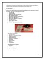
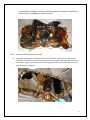
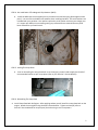
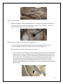
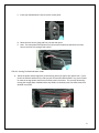
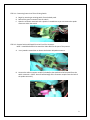
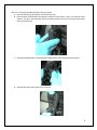
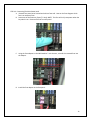
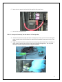
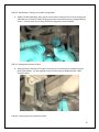
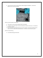
TM
Installation Manual
Also See the Companion Installation DVD included with your IMS Guardian™ purchase.
1
Congratulations on purchasing your IMS Guardian™. Before installing this system and reading this
installation guide, please watch the enclosed DVD that supplements this guide.
GETTING STARTED:
Inventory The Package: Once you have opened your IMS Guardian™ Box it is important to inventory
its contents: You should have the following in your box
a. Installation DVD
b. Installation Manual
c. IMS Guardian™ Warranty Work Sheet
d. IMS Trouble Shooting Card
e. IMS Guardian™ Asset Tags (Serial Number)
f. IMS Guardian™ Wire Harness
g. IMS Guardian™ Magnetic Chip Detector
h. Two Crush Washers
i. White Connector Coupler
j. Three Zip Ties
k. OPTIONAL: IMS HotLine Support Package
Required Tools For Installation
a. 8mm Hex Socket
b. Adjustable Wrench or 26mm Wrench
c. Standard Screw Driver
d. Jewelers Screw Driver
e. 10mm Socket with Ratchet
f. Oil Drain Pan
g. Oil Filter Wrench
h. Flash Light
i. Common Sense
Required Materials For Installation
a. Engine Oil
b. Oil Filter
c. Engine Sealant
d. Parts Cleaning Solvent
2
STEP ONE: Draining The Oil
A.
Remove Drain Plug From Sump Plate (Use 8mm Hex Socket)
(Note: In future oil changes, inspect and clean the IMS Guardian™ Magnetic Chip Detector.
Remove any collected ferrous material from the magnetic field collector. This must be done
during EVERY oil change to prevent false positive alerts.
STEP TWO: Remove, Inspect and Clean The Sump Plate
A.
Remove The Sump Plate: Using a 10mm Socket remove the 12 bolts/washers mounting the
sump plate to the engine. It is normal to have to pry the sump plate to break the seal.
Locate and pry on the two bosses on each side of the sump plate.
B.
Inspect and Clean The Sump Plate: Inspect the sump plate looking for any foreign debris
including but not limited to ferrous and plastic material. Using a mild solvent (mineral
spirits) clean sump plate. NOTE: REMOVE RUBBER OIL CONTROLL BAFFLES FROM SUMP
3
PLATE PRIOR TO CLEANNING: DO NOT CLEAN OR ALLOW ANY SOLVEMENT TO COME IN TO
CONTACT WITH THE RUBBER OIL CONTROL BAFFLES.
`
STEP 3: Inspection Of Oil Sump and Pickup Tube
A.
Inspection Of Sump Body, Oil Pickup Tube, and Anti-Foamers: Once you have removed the
sump plate and cleaned it, you will need to inspect the sump body, oil pickup tube, and the two
anti-foamers. Again you are looking for any foreign debris inside the oil pickup tube as that is a
common place for collection.
4
STEP 4: Pre-Installation of The Magnetic Chip Detector (MCD)
A.
Install the MCD into the sump plate just as you would a normal drain plug (hand tighten at this
point). Use one of the included crush washers when installing the MCD. Two crush washers are
included with your purchase. You need to replace the crush washer each time you change your
oil. Inspect your MCD prior to installing noting any collected ferrous material that may have
been collected on your work bench.
STEP 5: Sealing The Sump Plate:
A.
Prior to reinstalling the sump plate back on to the engine, you will need to apply the Porsche™
recommended sealant to your sump plate (refer to your Porsche™ Service Manual)
STEP 6: Reinstalling The Sump Plate
A. Install Sump Plate Back On Engine: After applying sealant you will install the sump plate back on the
engine. Attach the sump plate using the bolts removed earlier. Tighten and torque (refer to
Porsche™ Service Manual for torque specs) the bolts using a criss-cross pattern.
5
STEP 7: Tighten The MCD
A. Tighten The MCD Plug: Using an adjustable wrench or 26mm wrench, tighten the MCD to the
same torque specs as a normal drain plug (refer to Porsche™ Service Manual). If no torque
socket is available, tighten ¼ turn past hand tight.
STEP 8: Remove / Change Your Oil Filter and Fill Engine With Oil
A. With the sump plate and MCD installed, you will remove and change your oil filter.
B. After installing a new filter, fill the engine with your choice of engine oil.
HELPFUL HINT #1: Pre-Locate The Harness Access Location
A.
Source The Access Point Through The Chassis: Identify the easiest access point through the
chassis of the car to run your wiring harness. This access point will differ on the year and
model of your car. Typically this is on the bulkhead that separates the engine bay from the
cabin of the vehicle. Use a screwdriver to remove the rubber plug at the access point. In
rare occasions it may be required to drill an access point into the bulkhead. If this is
required, a rubber grommet (not included) must be used to protect the wire harness. In
addition, please inspect both sides of the drill point to insure no damage will occur from the
drilling process.
6
B.
Locate The Access Point Inside The Cabin: Once you have located the access point on the
bulk head of the engine bay, you will need to locate the same point in the cabin of the car.
You will need to remove the carpet, panels, and hardware in the area which your access
point is located.
STEP 9: Installing The Dash Interface
A.
Inspect Dash Panel For The IMS Guardian™ Mount Location: You will need to inspect your
dash panel to properly locate your IMS Switch. You will be pulling power from one of the
existing switches in the dash to supply power to the IMS Guardian™. NOTE: It is typically
easier to install the IMS Guardian™ Switch adjacent to a utilized switch in the dash. In some
cases all of the switch locations are utilized on one side of the dash, leaving all blank
switches on the opposite side (SEE VIDEO TUTORIAL). The IMSG Guardian™ has been prewired to accommodate this situation.
B.
Remove switch panel from console. The panel simply pops out by prying against it with a
flat head screwdriver. Care must be taken to avoid scratching the console.
C. Remove one of the blank block out plates in the switch panel.
7
C. Install your IMS Guardian™ Switch into the vacant panel.
D. Route the wire harness (plug end first) into the dash panel.
E. Note: The main power lead (red wire) may have to be temporarily taped to the primary
harness to aid in the routing of the system.
STEP 10: Routing The Switched Power Leads
A.
Route the power lead (orange wire) to the existing switch you plan to pull power from. If your
panel has all blank switches on the side you plan to locate the IMS Guardian™ on, you will need
to route the orange power lead from one switch panel to the other. This is easily achieved by
routing the orange power lead behind the cup holders on the dash panel. See video tutorial for
detailed instructions
8
STEP 11: Connecting Power Lead To An Existing Switch
A. Begin by removing an existing switch from the dash panel.
B. Remove the green connector from the switch
C. Open the connector terminals with a jeweler’s screwdriver so you can remove the spade
connector within the switch.
STEP 12: Remove Position #3 Spade Terminal From The Connector
NOTE: It would be beneficial to watch the Video DVD for this part of the process.
A.
Use a jewelers screwdriver to release the Position #3 spade connector.
B. Connect the white connector coupler (included) to the spade terminal removed from the
switch connector. (NOTE: Be sure beveled edge of the connector coupler faces the lock of
the spade connector.)
9
C.
Connect the white connector coupler into the black connector coupler of the orange power
lead wire.
D. Connect the spade terminal of the jumper wire (orange) back into the connector switch.
E. Reconnect the lock on the connector.
F. Reinstall the switch to the connector.
10
STEP 13: Connecting The IMS Guardian™ Warning Switch
A. Reinstall the existing switch back into the switch panel.
B. Place the black circuit board box and buzzer inside the dash console. There is no need to secure
the box. The box is self contained and will be held in place by harness in the small compartment
within the dash panel.
C. Connect your IMS Guardian™ Switch (already installed into the switch panel) to the wire harness.
D. Reinstall the switch panel back into the console.
11
STEP 14: Connecting The Main Power Lead
A. Remove fuse panel cover located at the driver foot well. Note on the fuse diagram which
fuse is an accessory fuse.
B. Locate one of the accessory fuses (7.5 Amp) NOTE: This fuse will only have power when the
key switch is on. Remove this fuse from the panel.
C. Using the fuse adapter on the IMS Guardian™ wire harness, reinstall the removed fuse into
the adapter.
D. Install the fuse adapter in the fuse panel.
12
E. Route the main power lead (red wire) through the fuse panel cover.
F. Reinstall the fuse panel cover.
STEP 15: Routing and Concealing The Wire Harness To The Engine Bay.
A.
Remove the necessary carpet and center console piece to route your wire harness along the
center console to the rear bulk head. You should have located this access point earlier in the
project.
B. Using a flat head screwdriver, tape the wire harness (plug end) to head of the screwdriver to
easily route the wire harness from the cabin back towards the engine bay. You may need
the help of a friend to push the wire through the bulkhead.
13
STEP 16: IMS Guardian™ Wiring: From Cabin To Engine Bay
A.
Modify The Bulk Head Plug: Once you have successfully routed your wire harness through the
bulkhead, you will need to modify the plug (previously removed) by cutting a passage half way
across it. This will allow you to easily reinstall the plug back into the bulkhead.
STEP 17: Routing Wire Harness To MCD
A.
Routing The Wire Harness To The MCD: Route the wire harness back to the MCD using the
factory wire holders. Use the supplied zip ties to further secure the IMS Guardian™ Wire
Harness in place.
STEP 18: Connecting The Wire Harness To MCD
14
A.
Connect the wire harness to the previously installed magnetic chip detector. Listen for an
audible “click” to ensure connection.
STEP 19: Check The System For Operation
A.
B.
Turn ignition to the on position (DO NOT START THE ENGINE)
The IMS Alert Warning Indicator Switch should be illuminated in an amber color. This indicates
the system is armed.
C. Press the IMS Alert Switch (lighted portion) to test for operation. The light should illuminate to
a red color and an audible alarm should be heard. This indicates a fully functional system.
STEP 20: Trouble Shooting
A.
See Trouble Shooting Card Enclosed
15