1
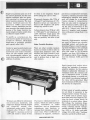
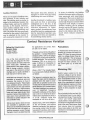
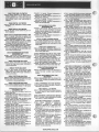
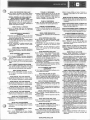
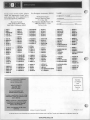
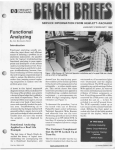
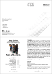
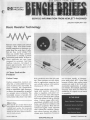
SERVICE INFORMATION FROM HEWLETT-PACKARD
JANUARY-FEBRUARY 1981
Basic Resistor Technology
Resistors seem simple and common
enough - they have been fundamental components in electronic circuitry from the early days of radio.
But a r e they really simple? Not
when you consider that a precision
potentiometer is actually a precise
instrument-grade sensor. Or that resistor networks a r e now laser
trimmed for accuracy. And t h a t
leadless resistors, developed i n
Japan approximately three years
ago, are beginning to appear in U S .
products.
A Closer Look at the
Products
Carbon Comps
Carbon composition resistors are
either hot- or cold-molded from mixtures of carbon and a clay binder. In
some versions, t h e composition
forms a monolithic rigid structure;
in others, the composition is applied
to a ceramic core or armature. The
hot-molded version is basically the
same product today that it was when
I
i
j
Editor’s Note:
(
notice the H P part number below? Each
issue of Bench Briefs will be identified by
a similar part number that increments
with each successive issue. Use this part
number to order extra copies and back issues (as stock permits).
first introduced more than 40 years
ago. These resistors are still widely
used in applications requiring lowcost, reliable resistors with resistive
tolerances of t 5% to t 1 W .
Carbon comp resistors are manufactured with resistive values of 10
ohms to megohms, and power ratings of 1/8to four watts. The largest
use, however, focuses on the 114-watt
units with values of 1000 to 100,000
ohms. Carbon comps offer wellestablished reliability and are still
being specified for military and
aerospace equipment. They also can
withstand higher surge currents
than carbon-film resistors. Resistance values, however, are subject t o
change upon absorption of moisture
and increase rapidly at temperatures much above 60°C. Noise also,..
becomes a factor when carbon comp
resistors are used in hi-fi and communication applications. A carbon
core resistor, for example, generates
electronic noise that can reduce the
readability of a signal or even mask
it completely.
OHEWLETT-PACKARD 1981
Part No. 5952-0105
WWW.HPARCHIVE.COM
Cal U V I I - I I I I I I
IFUlUUVl
u
U
.
"
ceramic cores with thin films of carbon applied (see Figures l a and lb).
Although carbon films are said to
offer closer tolerances and better
temperature coefficients than carbon comps, most characteristics are
virtually identical for a large
number of general-purpose, noncritical applications where neither
reliability, surge currents nor noise
are crucial factors. One distinct advantage though is price - typically
less than half that of a comparable
carbon comp.
Metal Films
Metal-film resistors are discretes
formed by depositing any of a
number of metal or metal-oxide
films on a suitable insulating core or
mandrel. The two most common
metals are nichrome sputtered on
ceramic and tin-oxide on ceramic or
glass. Other common techniques are
both precious metal and nonprecious metal-based cermets.
Cermet technology is the screening
or painting of finely powdered metals and powdered glass or frit in a
suitable liquid vehicle to form an ink
or paste on a porous ceramic substrate. Firing in an oven permanently bonds t h e metal to the
ceramic and evaporates the vehicle.
I
Carbon Film in Profile
."-..VU
Metal-film resistors a r e lasertrimmed or helixed (formed into a
spiral) to obtain the precise resistance value before a protective insulation coating is applied. As in the
case of carbon resistors, the 1000ohm to 100,000-ohm resistors with
114-watt ratings are in greatest use.
Precision usually runs +1% and
Temperature Coefficient of Resistance (TCR) is in the a 1 0 0 ppm/
degree C range for all t h r e e
Carbon-film resistors are manufactured by pyrolyzing a hydrocarbon
gas and depositing the carbon that
is produced onto cylindrical ceramic
cores; the process takes place
inside a quartz flask that is rotated in
a high-temperature kiln. Nominal
resistance values can be varied by
adjusting the processingtime for the
cores.
After capping me carDon-nim cores,
the films are spiral cut with a laser or
diamond wheel to increase the resistor's current path length and to
reduce its current path width. The
film geometry produced by the spiral
cut increases the resistance value
by several orders of magnitude. The
cut is automatically stopped when
the desired resistance value is
reached. The remaining processing
includes welding lead wires onto the
caps, encapsulation, testing and
color banding.
0 )
b
Film Deposit
(L
Cap
\
Quartz
Flask
Kiln
I
Spiral
===
=a=
=
=
Hydrocarbon
Gas
cores
Lead Weld
Coat
Test
Cores
Mark
Figure la. Carbonizing process for
making carbon-film resistors.
Hydrocarbon gas is pyrolyzed,
producing carbon that is deposited
onto ceramic cores.
technologies. Yet there are subtle
differences:
Cermet covers a wider resistance
range and handles higher power
than nichrome deposition.
Nichrome is generally preferred
over tin-oxide in the upper and
lower resistance ranges and can
provide TCRs that are lower than
50 ppm/"C.
Tin oxide is better able to stand
higher power dissipation t h a n
nichrome.
Figure 1b. Carbon-fiim production
sequence, from ceramic core to
finished resistor.
Wirewounds
Wirewound resistors have resistive
wire wound on a central ceramic
core. One of the oldest technologies,
wirewounds provide the best known
characteristics of high temperature
stability and power handling ability.
Nichrome is the wire in widest use
for this application.
The greatest number of wirewound
resistors is i n t h e 10-ohm to 1megohm region. Resistive tolerances
are +2% or better, and TCRs are
generally f 10 ppm/"C or better.
-1
r 1
A Description of Resistor Characteristics
Resistors will change value as a result of applied voltage, power, ambient temperature, frequency
change, mechanical shock, or
humidity.
The voltage coefficient is the rate of
change of resistance due to applied
voltage, given in percent per volt.
This characteristic is negative for
most resistors, although some
semiconductor devices actually
increase in resistance with applied
voltage. The voltage coefficient of
very high valued carbon-film resistors is usually rather large, while in
wirewound types the effect is usually negligible. Varistors are resistive devices designed to have a
large voltage coefficient.
The temperature coefficient (TC or
TCR) is the rate of change of resistance with ambient temperature,
usually stated as a percentage or
parts per million (ppm) per degree
Celsius. Many types of resistors
increase in value as temperature is
increased, while others, particularly
. .
.
hot-molded carbon types, have a
maximum or minimum in their
resistance curves which gives a
zero temperature coefficient at
some temperature. Metal-film and
wirewound types generally have
temperature-coefficient values of
less than 100 ppm/"C. Thermistors
are resistance devices designed to
have a large temperature
coefficient.
Thepower coefficient is the product
of temperature coefficient and
temperature rise per watt, which
gives a power coefficient in percent
per watt and indicates the change in
value resulting from applied power.
Frequency Characteristics of Resistors. Resistors change value
with frequency because of inductance, lumped and distributed
capacitance, dielectric loss, skin
effect, and eddy-current losses, plus
a few other minor effects as well.
Standard Resistors. A good
standard resistor is one that displays minimum change due to inductance, lumped and distributed
capacitance, dielectric loss, skin
effect, and eddy-current losses and,
even
more-important, is very stable
.. .
with time. Standard resistors up to
10 M R are usually wirewound. Stability is improved by low-tension
winding, heat cycling, and sealing in
a chemically inactive oil or gas.
1
The Thomas 1 - 0 resistor, which has
been the best available standard for
a long time, is bifilar wound of heavy
manganin wire in a sealed container. It has four terminals brought
out so that any four-terminal measurement will be independent of the
resistance of the connecting leads,
the terminals, and the contact between them.
New 10-kR standards are coming
into use. These use Evanohm wire
which can be treated to have a
temperature coefficient of less than
0.2 ppm/"C over a narrow temperature range. While these standards
are also four-terminal, lead resistance is much less critical at this
higher resistance value. However,
at this resistance level, shunt leakage resistance must be kept very
high and a guarded measurement is
recommended.
The range of resistance standards
extends down to 10 p 0 at which
level precision four-terminal shunts
used for high-current measurement
_
_
~
nave an accuracy of 0.04 percent.
While wirewound resistors over 100
M R have been made, film types are
usually used in this range and on up
to 1 0 1 3 ~ ~
.
f
-
Wirewound resistors are generally
classed as power or instrumentgrade products. Power wirewounds,
capable of handling as much as 50
watts, are wound from a coarser wire
that is uninsulated at the time of
winding in order to provide better
heat dissipation. Once it has been
wound, the unit is given a n overall
insulation coating of silicone.
Instirument-grade precision wireresistors are made from long
WOUlid
lengths of fine insulated wire. After
winding, these are usually conformally coated with a ceramic
material.
All wirewound resistors are classed
as air-core inductors of the solenoid
type. Therefore, inductive reactance
at high frequency alters the resistive
value. The seriousness of this problem is directly proportional with frequency. Special winding is useful to
cancel reactance at low frequencies.
WWW.HPARCHIVE.COM
Networks
Networks are assemblies of resistive
depositions and interconnecting
conductors on ceramic substrates.
The equivalent of from five to 15 resistors a r e typically placet
small ceramic substrate, whic
be packaged as a single in-lin
or dual in-line (DIP) product.
The extraordinary growth rate of
thick-film resistor networks is attributable to digital circuitry, particularly computers and computer
peripherals where there is a need for
clusters of similarly rated, lowpower resistors. Networks are used
to change voltage levels of digital
logic or to match logic families with
differing characteristics. They are
also used to terminate lines and
drive numeric displays.
Thin-film resistor networks are even
less standardized. They may be
packaged in DIPs, flatpacks or may
even be unpackaged. Thin-film
products may be used where a
higher performance is needed than
that afforded by thick film. Thinfilm networks use nickel-chromium,
tantalum-nitride and chromiumcobalt vacuum depositions.
Thin-film networks are typically
used in analog or linear circuits.
Ladder networks for digital-toanalog converters and current summing networks are typical.
Variable Resistors
The three different potentiometers
i n common use are the precision
multiturn potentiometer, the control
or panel potentiometer and t h e
The standard resistive tolerance for
the deposited resistive elements in a
thick-film network is 22% (down to
2 1/2% in some cases), with a TCR of
2 100 ppm/"C over the temperature
range of - 55°C to + 125°C. Precious
metal inks are used in the preparation of most thick-film resistor networks. The inks are fired into the
ceramics and the resistive elements
are laser trimmed t o achieve the
desired resistance values.
Precision pots a r e actually
instrument-grade sensors with outputs proportional to a precise shaft
setting, sometimes i n conjunction
with a turns counting dial. Figure 2
shows two examples of how precision
potentiometers can be used as sensors, These products have both
wirewound and non-wirewound resistive elements. Primarily because
of the need for longer mechanical
life, the non-wirewound resistive
elements were developed, with the
conductive plastic type the most
widely used. Later designs incorporated both elements into a hybrid of
conductive plastic coating on
wirewound. There a r e also some
cermet high-temperature precision
pots.
,
Helical Bourdon Tube-Actuated
Potentiometric Transducer
Bellows
Or Single Diaphragm
Diaphragm Or Bellows-Actuated
Potentiometric Transducer
Helical
Bourdon Tube
Applied
Pressure
The most popular parts are SIPS
with six, eight and 10 pins and one
less resistor per u n i t t h a n the
number of pins. The most popular
DIPs are those with 14 or 16 pins
and the most common configurations
are seven or eight parallel resistors
or 13 or 15 interconnected resistors
with a common pin. Power dissipation is typically less than 1/8-watt
per resistive ement.
It is estimated that 40% to 45% of all
thick-film networks used a r e
custom-made for specific customer
requirements. The custom models
are usually minor modifications of
the standard products.
trimming potentiometer, simply referred to as the trimmer.
Potentiometer
Pressure forces linear movement
of potentiometer wiper
The potentiometric technique measures
pressure by determining the position of a
.potentiometertap that is set by the linear
response of a bellows or diaphragm under
pressure, or by the rotary response of a
I
Internal pressure forces bourdon
tube to untwist, shifting
potentiometer wiper
helical bourdon tube under pressure. The
position of the potentiometer tap is converted to a proportional voltage output
when a constant ac or dc voltage is applied
across the potentiometer.
Figure 2. Two examples of a precision Potentiometer used as a preclse
instrumentgrade sensor.
WWW.HPARCHIVE.COM
r
Single-turn precision pots use all of
the resistive elements, but the more
complex multiturn pots are generally restricted t o wirewound and
hybrid resistive elements. The most
common multiturn pots a r e t h e
three-turn (lO80O) and 10-turn
(3600")versions. Multiturn pots are
more accurate than single-turn pots
because of the longer resistive elements (single-turn pots usually have
an effective length of 360").
To qualify as a precision pot, the
unit must be capable of linearities of
at least 1%.However, off-the-shelf
single-turn or multiturn precision
pots typically offer 0.25%.
Wirewound elements offer TCRs of
5%.
& 50 ppm/"C and tolerances of
Resistive values are typically 10
ohms to 100 megohms and power
ratings may exceed a watt.
Carbon elements have TCRs of 5 400
to t 8 0 0 ppm/"C and tolerances of
+20%. Resistive range spans 100
ohms to 2 megohms and power ratings are generally less than a half
watt.
Other Variable Resistors
Control or panel potentiometers are
made with carbon compositions,
There are other variable resistors
that do not rotate or slide in order to
---:
-L
&Le:- ---:-A
^_^^
---l.-C I l a l l g l 2 L I l e l l - 1~eSIBLZIIlC.X V a l u e .
2
WIIl3WUUIIU
69
10 ohms to 2.5 megohms. Typical
power ratings are 1.2 to 1watt.
---1
-----A
- 1 ----A-
a l l U C l 3 Z I l l l 2 L l2ll2Illl2IlLS.
There are also modular panel pots
with interchangeable resistive elements that permit ganging and the
addition of switches.
----
mI.-
Ille
thermal and light sensitive properties of certain elements can be
used to produce heat or light variable resistors.
1
tl
(
Trimmers are offered in wirewound,
non-wirewound, multiturn, and
single-turn designs with the largest
use centering around nonwirewound cermet units. Cermet
elements offer TCRs of 5 1 0 0 to
+250 ppm/"C, tolerances as low as
+10% and resistive values of from
II
-
Thermistors (thermal-sensitive resistors), which are used t o protect
power transistors i n audio
amplifiers, and as temperature
transducers, may decrease or
increase their resistance as tempera t u r e rises. Their coefficient of
resistance (if negative, resistance
goes down as temperature increases;
if positive, resistance increases with
temperature) specifies how resistance will change for a one-degree
Celsius change i n temperature.
They are also rated in catalogs by
their resistance at 25°C) and by giving the ratio of resistances at 0°C
and 50°C. Values vary from 2.5
ohms to 1 megohm (room temperature), with power ratings from 0.1 to
1watt.
Photocells (light-sensitive resistors)
a r e used i n electric-eye circuits,
streetlight control, and similar applications. They are rated by specifying their resistance at low and high
light levels. These typically vary
frnm
Grin nhmo t n
u*l* W u u
W
~
u u~
lln
A L W
~
L;lnhmo
A A ~
l U l l l l~a U
(bright), and from 100 kilohms to
200 megohms (dark). Power dissipation lies between 0.005 and 0.75
watts.
Strain gauges and carbon microphones are examples of pressuresensitive resistors. As the resistive
element is physically deformed, its
resistance varies. If a constant voltage is impressed across a carbon
microphone element, a variable current, which is an electrical analog of
the voice, will be generated. Most
have resistances of 500 ohms or so in
the absence of compression.
A final variety of variable resistors
you are likely to encounter is the
voltage-sensitive resistor (Varistor).
It is chiefly used to protect equipment from power-line surges by limiting the peak voltage across its
terminals to a certain value. Above
this voltage, the resistance drops,
which in turn makes the voltage decrease. Catalogs specify voltagevariable resistors by power dissipation (0.25 to 1.5 watts) and peak
voltage (30 to 300 volts). Varistors
typically cost $2.00 to $6.00 each.
U
II
1
Leadless Resistors
There are two types of leadless resistors currently in use: tubular and
chip. The tubular style is similar in
shape to the traditional resistor, but
without leads, and can be soldered
directly to PC boards. However,
some studies indicate that as PC
boards warp with handling and
time, the stress that was previously
absorbed by the resistor’s leads must
now be absorbed by the resistor itself, causing the component to crack.
The square chip style, however, is
designed to bend with the board,
eliminating this cause of failure.
Another drawback to leadless resistors, and one t h a t is preventing
widespread use in the US.,is the
lack of readily available automatic
insertion equipment. I n J a p a n ,
many product manufacturers have
solved the insertion equipment problem by manufacturing their own,
and some U.S. firms are reported to
be considering similar moves.
In terms of reliability, the leadless
resistor eliminates many of the problems associated with axial-leaded
components. There are no lead wires
or end caps to become disattached,
and in high frequency circuits where
component lead length is critical,
leadless resistors can be soldered
directly into the HF circuit. Another
benefit is that the chips can be soldered to the bottom side of the PC
board which reduces component
density.
Contact Resistance Variation
Defined As Potentiometer
Dynamic Noise
By Jack Thayer,
Hewlett-Packard
One of the more persistent problems that has plagued the electronics industry for many years has
been “noisy pots.” Generally, the
gross portion of this noise is attributable to foreign material, corrosion
and wear in the element-to-contact
interface and is readily identified in
both new and in-service pots.
the applications are correct, there
are still a lot of rejects.
This gets us down to the nitty gritty of
the problem - Contact Resistance
Variation (CRV). CRV is the plague
of sensitive circuits that require adjustable elements. The net result of
excessive CRV on a circuit is to
make it difficult or impossible to
make adjustments to some predetermined level.
What is CRV? The Variable Resistive Components Institute defines it
as follows:
acteristics of wirewound pots and
trimmers, the reverse is true of
non-wirewound parts. These types
have exhibited almost continuous
improvement over the past several
years as industry requirements
pressured for better performance at
lower and lower signal levels. Most
sources of gross noise defects (except wear) have generally been
eliminated or greatly reduced in the
pots available today.
The apparent resistance seen between the wiper and the resistance
element when the wiper is energized with a specified current and
moved over the adjustment travel in
either direction at a constant speed.
The output variations are measured
over a specified frequency
bandwidth, exclusive of the effects
due to roll-on or roll-off of the terminations and is expressed in ohms or
% of Rt. (Industry limits this
bandwidth to: 100 Hz to 50 kHz.)
Still we have rejects. Some of these
are traceable to application problems such as resolution (tryingto set
the pot near the end of its travel), or
carrying excessive current through
the wiper. Even if we determine that
Stated simply, CRV is the reflection
of the non-perfect, non-uniform
electrical connection that exists as
the moving contact rubs the resistive element’s surface, and is sometimes referred to as current noise.
wniie m e has changed in the char-
WWW.HPARCHIVE.COM
Postulations
A rheostat (two teminal device) application of a trimmer will result in a
higher CRV than the same trimmer
used in a voltage divider (three terminal) application. This is because
in rheostats, all the current passes
through the wiper contacts, so as
the current goes up, so does the
.
Restrict wiper current to 10 mA
maximum unless it can be shown
that higher current levels do not produce unacceptable levels of CRV.
This recommendation is made in
spite of the manufacturer’s rating of
100 mA absolute maximum for their
wipers. Tests show that CRV rises
rapidly in direct proportion to wiper
current.
Do not include the first and last 10%
of mechanical travel in your electrical adjustment range. These are the
“roll-on” and ‘‘roll-off’’ areas which
usually exhibit a noise spike of several times the magnitude of the CRV
level of the rest of the trimmer. Note
that industry does not consider
these noise spikes to be CRV and
therefore do not includethem in their
specifications.
/1
Customers
_
_
_
I
-
WWW.HPARCHIVE.COM
"___
~..
-~-
CUSTOMER SERVICE TRAINING CALENDAR FOR 1981
LOCATION
TUITION
Colorado Springs Division
1900 Garden of the Gods Road
Colorado Springs, CO 80907
(303) 598-1900
Colorado Springs Division
$ 300/student
Jerry Lopez
$1,25O/student
Jerry Lopez
Colorado Springs Division
$ 300/student
Dick Browne
Colorado Springs Division
$ 350/student
Dick Browne
March 9 - 13
September 21 - 25
March 2
September 21
March 3
September 22
Colorado Springs Division
$ 4001student
Dick Browne
Colorado Springs Division
$
200/student
Margie Collins
Colorado Springs Division
$ 200/student
Margie Collins
February 23
September 14
February 24 - 25
September 15 - 16
February 25 26
Scptembcr 16 - 17
February 27
September 18
February 4 - 6
September 23 25
Colorado Springs Division
$
200/student
Margie Collins
Colorado Springs Division
$ 250/student
Margie Collins
Colorado Springs Division
$ 250/student
Margie Collins
Colorado Springs Division
$ 200/student
Margie Collins
Colorado Springs Division
$ 300/student
Margie Collins
January 19 - 30
February 23 March 6
March 30 - April 10
May4-15
June 15 - 26
July 20 - 31
August 24 - September 4
September 28 -October 9
November 2 - 13
December 7 18
January 19 - 23
March 9 - 13
Mav
. ~..1 R
.- 22
Jul; 20 - 24
September 28 -October 2
November 16 - 20
Loveland Instrument Division
815 Fourteenth Street, SW
Loveland, CO 80537
(303) 667-5000
$2,10O/student
Sandy Selleck
Technology Trair ig
Digital Troubleshooting
Techniques
March 17 - 20
May 12 - 15
Instrument Service Ccnter
333 Logue Avcnue
$ 350/student
Debra Conley
8901A Modulation Analyzer
Signal Analysis
Models 8566A Microwave/8568A
Programmable
Ikbruary 23 - 27
September 14 1 8
$ 400/student
Jim Boyer
8565A Spectrum Analyzer
November 2 - 6
San ta Rosa Division
1400 1;ountain Grove Parkway
Santa Rosa, CA 95404
(707) 525-1400
Santa Rosa Division
WWW.HPARCHIVE.COM
$ 350/student
Jim Boyer
DATES
CONTENT
Logic Analyzers
Logic State Analyzer Maintenance
Models 1610A/B, 1611A, 1615A,
1640A (2.5 days each)
Microcomputer Development
System Model 64000
Scopes and Displays
Models 1715A/1725A (Order
HP NO. 5955-4146)
Models 1740A/1741A/1742A/
1744A (Order HP No.
5 9 5 5 4 147)
Models 1980B/1950A/ 19860A
(Order HP No. 5955-8046)
Models 1302A, 1304A
PIN 5955-8049
Models 1310A/B, 1311A/B,
1317A/B, 1321A/B
P/N 5955-8050
Models 1332A, 1333A, 1335A
P/N 5955-8051
Model 13368
P/N 5955-8052
Model 1338A
P/N 5955-8053
Model 1340A
P/N 5955-8054
Model 1350A
P/N 5955-8055
Automatic Test
Circuit Test Systems
Model 3060A
-
March 16 27
March 2 - 13
August 10 - 21
- 25
-7
- 19
March 23
October 5
March 16
September
COORDINATOR
"7
28 -October 1
-
-
-
-
Model DTS-70
Loveland I
~
-
m
m
m
r
m
m
m
m
m
m
m
m
m
m
m
m
m
m
m
m
Oscilloscopes
Hewlett-Packard, Colorado Springs Division, is offering
service training seminars to customers on most all models
of oscilloscopes including the new HP 1980 Oscilloscope
Measurement System. All training will be conducted at
Colorado Springs, CO, on the dates shown on the training
calendar.
m
m
m
= =
m
m
1302Al1304Al1310Al13llAl1317Al
1321A Large Screen Displays
These seminars are directed to calibration and repair
technicians and teach operation, circuit-theory, calibration and troubleshooting to component level repair. Attendees should have some prior knowledge of standard
oscilloscope circuits, such as differential amplifiers, integrators, comparators and basic logic devices.
k
Large-screen displays are also covered in a 1-day course
consisting of theory, calibration, troubleshooting and
repair.
1700 Series, General Purpose Applications
1980A/B Oscilloscope Measurement System with
Optional 1950A 4-Channel P
19860A Digitizer
, - ’
------7
I
These 3 and 4-day oscilloscope seminars are taught to
component-level of troubleshooting and repair. Popular
options such as state-display and digital-multimeter and
AT options are included.
1332Al1333Al1335Al1336Stl340ASmall Screen
Displays
-.
f
These small-screen displays are covered in a 1-day class
consisting of theory (including variable persistence and
storage), calibration, troubleshooting and repair.
This 5-day seminar is directed to calibration and
technicians with prior knowledge of standard oscilioscope
circuits, signature analysis, and digital/analog circuitry.
A background in 8080 microprocessors and ANSII logic
symbology (HP booklet 5951-6116) is also recommended
to help the technician better understand the 30 schematics covered.
The first half of the first day covers CRT basics. 1ifterward instruction deals primarily with digital circ:uitry
(control). Other areas covered are the power suPPlY 9
analog circuitry (measurement) and the optiona1 4channel and digitizer plug-ins.
In case of insufficientenrollment, classes may be canccelled.
........... Microprocessors . . . . .
UD
FIRS’Ir DAY:
. A nalog vs. digital.
Signal transmission techniques.
a) One wire, one signal.
b) Digital.
c) Open collector drivers.
d) Three-state drivers.
o w‘orkshop - four hours of hands-on
fa.miliarization using a n Intel 8085
brised microprocessor trainer.
SECOINDDAY:
0 Introduction to programming.
a) Flow charts.
b) High level language.
c) Machine language.
d) 8085 Command set.
0 Algorithmic State Machine Concepts
0 Workshop - four hours of hands-on experiments using logic analyzers and
oscilloscopes to view correct microprocessor operation.
This is an intense 1-day course designed to provide the
service technician with enough fundamental knowledge and expertise to troubleshoot an instrument with
HP-IB type problems.
I
The day’s activities will include:
0
0
0
0
”7
Introduction to IEEE-488 (history, use in systems)
HP-IB bus structure, protocols, and specifications
HP-IB troubleshooting tool - HP 59401A Bus
Analyzer
Troubleshooting exercises on “bugged” instruments
THIRD DAY:
0 The Intel 8085 Microprocessor.
0
a) Block diagram.
b) Timing diagrams.
c) Analysis of pin functions.
d) Assessing improper operation.
Workshop - four hours of troubleshooting
experiments on the microprocessor trainer
using pulsers, probes, current tracers and
the signature analyzer.
FOURTH DAY:
Afternoon workshop sesslons provide students with hands-on
familiarization using the 50351 or 5036A Trainer and HP test equipment.
The micro-computer.
a) Micro-computer memories.
b) Input/output ports.
c) Keyboards.
d) Displays.
Analyzing self-test features.
Workshop - four hours of troubleshooting
experiments on the microprocessor trainer
using pulsers, probes, current tracers and
the signature analyzer.
WWW.HPARCHIVE.COM
1
..... ............. .......... . Digital . . . . . . . . . .
4B
FIRST DAY:
Analog vs. digital.
IC Technology: DCTL, RTL, DTL, CTL, TTL, ECL,
EECL, HTL, MOS, 12L.
Specialized tools and techniques to troubleshoot
these technologies.
Workshop - four hours of hands-on experiments
with gates and troubleshooting tools.
SECOND DAY
0
0
0
0
0
The course is roughly 40% lecture and 60% workshop.
At the end of seminar the student will be able to:
'3 HP-IB
Describe the function and use of all 16 lines on
Control listeners and talkers with an HP 59401A
Analyzer
Identify bus problems down to the component level
with the analyzer and decide on the next step towards repair.
THIRD DAY:
0
0
0
P
3
Logic Symbology.
Positivernegative logic notation.
Understanding the implication of logic schematics.
Implementation of logic gates: AND, OR, NOR,
NAND, XOR, Wired-OR.
Decoders and their uses.
Comparators and their uses.
Flip-flops: R-S, D, J-K (standard and master-slave).
Workshop - four hours of hands-on experiments
with decoders, comparators and flip-flops.
Students will also have an opportunity to use modern
tools to troubleshoot faults in a printed circuit
assembly.
Often encountered circuits containing flip-flops:
Counters (BCD and binary, synchronous and ripple),
dividers, shift registers, ring counters.
Numbering systems including binary, BCD, octal
and hexidecimal.
Introduction to binary math including half and full
adders.
Workshop - four hours of hands-on time building
and debugging counter circuits.
FOURTH DAY:
0
0
3
0
0
0
ROMSPROM (masked, E and UV).
RAM'S: bipolar and MOS (static and dynamic).
Typical failures and the troubleshooting difficulties
encountered with ROM'S, PROMS and RAMS.
Typical memory addressing techniques.
Modern display technologies, their application and
common failure modes.
Introduction to the ROM controlled device with emphasis on methods used to fault isolate.
Workshop -four hours of experiments leading to the
building of a functioning strobed display device.
Individual applications or problems are addressed during workshop sessions.
tic Test
? 3060 Circuit Test System
Service Seminar in
Loveland, CO
See 1981 Calendar for Dates
COURSE CONTENT
LECTURE AND LAB
I.
11.
111.
IV.
V.
VI.
VII.
VIII.
IX.
X.
XI*
XII.
'1
Introduction to Course, System, and BTL.
Review of HPL and HP-IB
System Control Panel
System Multiplexing
3496A Scanner Troubleshooting
11353Al11453A Diagnostic Fixtures
341961-3 Scanner Power Supply
11253A System Power Module
Analog In-Circuit Testing
Transfer Testing
3253A Analog Stimulusmesponse Unit Theory of
Operation
3253A Analog StimulusEtesponse Unit
Calibration
XIII. 3253A Analog StimuluslResponse Unit
Hardware Familiarization
XIV. 3253A Analog Stimulus/Response Unit
Troubleshooting Exercises
XV. 3453A Digital StimuluslResponse Unit
Programming
XVI. Static Pattern Testing
XVII D.U.T. Power Supplies ,
XVIII. D.U.T. Clock
XIX. 3453A Digital Stimulus/Response Unit
Troubleshooting
XX. System Troubleshooting
PREREQUISITES
1. 9825A HPL Programming
2. 9885M HPL Programming
3. Knowledge of HP Logic Symbology
4. Knowledge of Operational Amplifier Circuits
5. Knowledge of Basic Logic Circuits
All the above prerequisites are mandatory.
The standard repair consists of the
following steps:
I
HP Service Agreements:
That Extra Measure of Confidence
And
7 Standard Repair and Calibration Prices:
Where Costs Are Known in Advance
1. The unit is inspected for damaged
parts, missing hardware, burnt wiring o r marginal components. All
necessary repairs are performed.
2. The product safety service note
file for the unit is reviewed and all
mandatory safety modifications are
performed. Copies of the relevant
safety service notes describing the
modifications are attached to the
instrument.
3. If any other safety modifications
and updates are recommended that
will improve the reliability or performance of the instrument, the
customer is first contacted for authorization. The cost of any such
modifications is added to the standard repair price.
4. The operation verification is performed as outlined in the instrument’s manual to gain reasonable
confidence that the product is meeting its specifications.
or
The age of hybrid microcircuits, LSI
chips, and microprocessor-controlled
instruments is here. More capability
packed into a smaller package is a
tremendous benefit, but these complex circuits and high-technology
components can also mean more expensive repair and maintenance
costs.
Hewlett-Packard has developed its
own high-technology testing and
troubleshooting instruments, and
combined them with two programs
to help reduce repair costs by reducing turn-around-time.
. 9
a
-3
One program helps reduce the costs
of routine repair of HP instruments
which break down in normal use.
The other program provides the
equivalent of a health insurance policy for your instrument.
Both programs operate on the basis
of fixed prices. The cost is guaranteed (for a maximum of 30 days) so
even if actual service time and materials exceed this fixed price, you
pay no more. (The only exceptions
a r e damages incurred by abuse,
misuse, or accidental damage.)
What Type of Service Can
You Expect on Fixed Price
Repairs and Calibration???
First of all let’s establish the definition of “Instrument Repair” and
“Calibration.”
HP defines “Instrument Repair” as
follows:
“Instrument Repair consists of correcting all malfunctions, both electrical and mechanical that restrict the instrument from meeting
its published specifications. Repair
includes an operation verification
to gain reasonable confidence that
the product is meeting its
specifications.”
If the customer has specified repair
and calibrate t o specifications, a
complete calibration is performed as
described below.
5. To make certain that the instrument conforms to current safety
standards, an after-service safety
test is performed.
HP defines “Instrument Calibration” as follows:
“Instrument Calibration consists of
performance testing and any
required adjustments that will bring
the unit into conformance a s
specified in the Instrument Operating and Service Manual. In all cases,
HP’s calibrations are traceable to
the National Bureau of Standards or
other international standards
organizations.”
This calibration is documented with
a “Certificate of Conformance” that
is returned with the instrument.
/7
these parts is necessary, you will be
contacted and quoted the additional
cost before work is begun.
In addition to the standard repair
price described above, there is a low
“mini-repair price” which is common
to all models on the program. Should
the repair take less than an hour
and require nominal parts ($10 or
less), a “mini-repair price” of $55
will be charged.
.
.
STREP is intended to simplify the
routine quotation of HP instruments
which break down in normal use.
Contact your local HP Service Center for a list of prices and eligible
instruments. Instruments requiring
overhaul or repairs necessitated by
abuse, misuse or accidental damage
are ineligible for the program. HP
will, of course, continue to service
such products, and provide quotations based on actual time and
materials.
Other basic guidelines for the
Standard Repair Program are as
follows:
0 Standard prices apply to repairs
performed during regular HP working hours.
0 Shipping costs and sales or use tax
(if applicable) will be added to the
standard price.
0 Any consumables which are
required, such as power cords, test
cords, cables, test probes and cable
assemblies, batteries, paper tape,
and software, etc., will also be added
to the standard prices (unless otherwise noted on price list).
0 Customer-specified modification,
kits, and updates to instruments are
excluded from the program.
Certain instruments with special
options may be excluded from the
program. We will notify you in this
event.
Instrument mainframes and
plug-in units each have a standard
repair price. In some cases the repair
price could be the sum of the mainframe and plug-ids) Standard Repair prices.
For nearly 40 years, HewlettPackard ha‘s helped customers
obtain optimum performance from
their instrument investment. The
HP Service Agreement program
provides that extra measure of confidence, and assures you of prompt
attention and comprehensive maintenance - in other words, professional quality service t o complement your professional quality
instrument.
164OA-12. All serials. Recommended modifications to
the CRC or SDLC options to improve performance.
16408-1, Serials 2019A00294 and below. Modification
to prevent latch up on + . I 2 volt supplies.
16408-2. Serials 2028A and below. Recommended
modifications to the CRC or SDLC options to improve performance.
4030lBB PORTABLE AC VOLTMETER
403BIBB-98. Serials 0986A20520 and below. Recommended battery replacement for improved
performance.
410C ELECTRONIC VOLTMETER
41OC-19. All serials. Recommended modifications to
A3R5 and A6R20 during service due to vendor
non-availability of parts.
1715A OSCILLOSCOPE
1715A-6. All serials. Recommended attenuator detent
wheel replacement in the event of failure.
412A VACUUM TUBE VOLTMETER
Need Any
Service Notes?
They’re free!
Here’s the latest listing of Service
Notes. They recommend modifications to Hewlett-Packard instruments t o increase reliability, improve performance, or extend their
usefulness.
b
Use the order form at the rear of
Bench Briefs to select the notes that
relate to your instruments.
7
236A TELEPHONE TEST OSCILLATOR
236A-4. Approximate serials 1107A07800 to
1~07A08100.Front cover modification to property
turn the instrument off when the cover is installed.
3468 NOISE SOURCE
3468-1. Serials 2015A and below. Modification which
reduces the time the source requires to turn off to
improve noise-off measurements.
412A-9C-S. All serials. The set screws on the ”volts”
probe must be frequently checked to insure that the
protective insulation is in place.
1725A OSCILLOSCOPE
1725A-6. All serials. Recommended attenuator detent
wheel replacement in the event of failure.
432C POWER METER
1740A OSCILLOSCOPE
432C4A. Serials 1906A and below. Recornmended
auto range assembly replacement to eliminate
software related time-out problems when under
computer control.
174OA-16. All serials. Modification to improve connector mating reliability between A3 vertical preamp
and A5 vertical output PC boards.
1743A OSCILLOSCOPE
606AIB SIGNAL GENERATORS
1743A-3. An serials. Modification to improve connector
mating reliability between A3 vertical preamp and
A5 vertical output PC boards.
606AJE12. 606A all serials; 6068 serials 1862A and
below. Recornmended replacement for modulation
and RF output meters.
1980NB OSCILLOSCOPE
895A POWER SUPPLY
1MaWB-2. All serials. Recommended fast blow f u a
for proper line fusing to protect internal circuitry.
895A-3. Serials 1501A 01153 and below. Recommended part substitution in the event of SCR failure.
Supersedes 895A-1.
3W0A UUAHU 1 tS I S T S I EM
306OA-10A. All serials. Notification of 3060A system
software revision. IPG revised to 2014.
3060A-14A. All serials. Notification of 3060A system
software revision. CCD revised to 2027.
3060A-15. All serials. Software modification. CCD revision 2027 modification of “CNTRLR” program for
proper operation during the controller test.
3060A-16. All serials. Notification of 3060A system
software revision. CCD revised to 2036.
1610AIB LOGIC ANALYZER
1610A-11. Serials 1936A and below. Notification that
rebuilt power supplies are now available for
replacement.
161OA-I 2. Serials 1940A. Recommended ROM replacement kits in event of a ROM failure.
161052. Serials 19408 and below. Recommended
ROM replacement kits in event of a ROM failure.
3253A ANALOG STIMULUS
RESPONSE UNIT
1640AIB SERIAL DATA ANALYZER
1640A-10. All serials. Modification to prevent latch up
on r 12 volt supplies.
164OA-11. Serials 1827A and below. Recommended
keyboard replacement to improve performance.
WWW.HPARCHIVE.COM
I
--
--
-
3253A-2. All serials. Correction of source amp current
compliance check test limits on ASRU calibration
tape 03253-10002.
-”
3403C TRUE RMS VOLTMETER
3403C-8. Serials 1452A04110 and below. Recommended modification to improve performance in
certain applications when a small input signal with
large common mode noise superimposed is
measured.
344OA DIGITAL VOLTMETER
344OA-19. All serials. Modification to improve stability
of display.
3465A DIGITAL MULTIMETER
3465A-58. All serials. Correct replacement pari numbers for batteries.
3497A DATA ACQUlSlTlONlCONTROL UNIT
3497A-1. All serials. Instructions for making a blue
stripe board exchange for the 03497-69510 thermocouple compensation connector board.
3497A-2. Serials 201 1A00359 and below. Installing
analog and digital extender connectors for interfacing between the 3497A and 349BA extender.
3497A-3. Serials 201 lAOOl60 and below. Outguard
EPROM to ROM update to improve performance.
3497A-4. All serials. Instructions for making a blue
stripe board exchange for the 03497-69502 mainframe inguard controller board.
35558 TRANSMISSION AND NOISE
MEASURING SET
3745AJB-47. All serials. Preferred replacement of
phase lock loop IC 1826-0407.
3745AJB-48. All serials. Preferred replacement for
NPN transistor 1854-0071.
3745AJ0-49. All serials. Preferred replacement of
zener diode A313CR5, 11, and 17.
3745NB-50. All serials. Preferred replacement of
Option 050 ROM 5090-0805.
3747AlB SELECTIVE LEVEL
MEASURING SET
3747AJB-17. 3747A serials 195OU and below; 37470
serials 1924U and below. Modification to eliminate
excessive spurious signals from 2nd mixer A318.
3747AJ0-18A. All serials. Preferred replacement of
varactor diode 0122-0059.
3747NB-19. All serials. Preferred replacement of
phase lock loop IC 1826-0407.
3757A-1 8.5 MHz ACCESS SWITCH
3757A-1. Serials 1948UOO230and below. Modification
to allow proper operation when two or more instruments are cascaded and the control path is via the
coaxial cable.
3762A DATA GENERATOR
3762A-3. Serials below 1812U00421 (Options 201,
202, 330). Modification to eliminate incorrect error
rate on ternary data output.
3779AlB PRIMARY MULTIPLEX ANALYZER
35550-3. Approximate serials 0992A06150 to
0992A06950. Front cover modification to properly
turn the instrument off when the cover is installed.
3580A SPECTRUM ANALYZER
3580A-8. Serials 1415A-03440 and below. Recommended low voltage power supply modification to
improve performance.
3581AlC WAVE ANALYZER
3779A-18. Serials 2003U-00205 and below. Modification to improve reliability of power supply.
3779A-19. All serials. Preferred replacement of encoder integratedcircuit HP part number 1820-1851.
37798-19. Serials 200511-00265 and below. Modification to improve reliability of power supply.
37798-20. All serials. Preferred replacement of encoder integratedcircuit HP part number 1820-1851.
378OA-20. Serials below 1915U-01048. Modificationto
prevent "sync loss" condition under mechanical
vibration.
3582A SPECTRUM ANALYZER
3968A INSTRUMENTATION TAPE
RECORDER
3585A SPECTRUM ANALYZER
3585A-4. Serials 1750A00740and below. Identification
and service compatibility between I.F. filter boards.
3745AlB SELECTIVE LEVEL
MEASURING SET
-I
1
3968A-19. Serials 2009A01192,01193,01194,01195,
01202, 01205. Correction for possible HP-IB power
socket miswire.
4140A pA METEWDC VOLTAGE SOURCE
4140A-5. Serials 1917JOO270 and below. Remedy for
malfunction of key controls.
4262A DIGITAL LCR METER
3745AJB-18D. Serials 1812U and below. Retrofit kit for
special Option H07.
3745AJ0-308.3745Aserials 203211 and below; 37450
serials 2030U and below. Preferred replacement of
A109 memory assembly.
3745NB-37. 3745A serials 1930U and below; 37450
serials 1942U and below. Modification that improves the suppression of line radiated RFI.
3745NB-38A. All serials. Preferred replacement of
varactor diode 0122-0059.
3745AJB-39. Serials 1532U and below. Preferred replacement of A108 CPU assembly.
3745NB-40. Serials 1748U and below. Preferred replacement of A202 reference frequency assembly.
3745NB-41. Serials 1726U and below. Preferred replacement of A203 N3 programmable dividc3r.
3745NB-431. Serials 172611 and below. Prefered replacement of A206 S I 2 VTO assembly.
1645U and below. Prefeirred re3745NB-43. Serials
-. assembly.
piacemenr 01,A Z I ~1 i o MHZ niter
3745NB-44. Serials 1645U and below. Preferred replacement of A216 10 MHz filter assembly.
3745NB-45A. Serials 1751U and below. Prefened re-
.-~-
'9-
4
4275A MULTI-FREQUENC
3780A PAlTERN GENERATOR/
ERROR DETECTOR
3581AJC-6. 3581A serials 1351A-01300 and belcw
3581C serials 1411A-01015 and below. Recomto
mended low voltage power supply modification
improve performance.
3582A-8. All serials. Recommended replacement farIS.
3582A-9. Serials 1809A 01866 and below. Front paiiel
modifications to improve performance.
4274A-5. Serials 185OJ00160and below. Modification
to prevent parasitic oscillation at low frequencies.
4274A-6. Serials 185OJ00235and below. Modification
of the A6 oscillator board to improve performance of
the "zero offset adjustment".
4274A-7. Serials 1850J00235 and below. Recommended A9U1 and A9U5 PROM replacement to
improve performance during "zero offset adjustment", and when measuring a low impedance DUT
(approximately 0 R or 0 S).
4274A-8. Serials 185OJOO175 and below. Recommended PROM replacement for Option 0011002
(DC bias) to improve performance and eliminate erroneous error message "Err 8' which may appear
on DISPLAY A when the power switch is turned on
and the DC bias switch on the rear panel is set to
one for the INT positions.
4274A-9. Serials 185OJ00235and below. Modification
to prevent illegal display "9.99999'.
4274A-1OA. Serials 1850J00385 and below. Modification to prevent newly installed integrators from
creating erroneous counts causing the measured
value to be out of the specified range in performance test.
4274A-11. Serials 1838J00135 and below. Modification to A7/A9 boards to prevent the instrument from
periodically exhibiting a wide fluctuation of displayed measured values.
4274A-12. Serials 1838J00101, 106, 108, 110-116,
120. 121. Modification to improve memory backup
battery.
4274A-130. Serials 2031JO0800 and below. Modification to prevent the cable assemblies on the bottom
side of the mother board from being pierced by the
sharp pins of the PC board connectors.
4274A-14. Serials 2019J00760 and below. Supplemental information to service notes 4274A-4, 7,
and 11.
4262A-12. Serials 2022J02300 and below. Elimination
of trouble caused by zener diode A13CR15/16
replacement.
427049 AUTOMATIC CAPACITANCE BRIDGE
4270A-13. All serials. Proper identification of the cable
color code on T1 power transformer.
4274A MULTI-FREQUENCY LCR METER
4274A-1. Serials 1838J00114, 1838J00116,
1838J00118,
1838J00119,
1838J00120,
1838JOO122, 1838JOO129. and 185OJOO136. Modification to improve DC bias voltage (Option 001/
002) accuracy.
4274A-2. Serials 185OJO0460 and below. Modification
to improve oscillator level when performing the A3
"test signal level monitor adjustment" described in
the service manual.
4274A-3. Serials 185OJOO540 and below. Modification
to provide sufficient current through the DUT.
4274A-4A. Serials 1850J00207, 1850J00209,
1850J00210,
1850J00212,
1850J00214,
185OJ00220, 1850J00223 thru 1850J00230, and
1850J00232 thru 1850J00235. Recommended
A9U1 and A9U5 PROM replacement to improve
performance after "open and short zero-offset adjustment" has been performed.
4275A-1. Serials 1851J00302,OO;~I, U U L J J . UULJO IV
00288. 00285 to 00281, 00278 to 00276, 00274,
00272 and below. Modification to improve 1 WH
measurement at 10 MHz with 1 meter test leads.
4275A-2. Serials 1843J00129 and below. Recommended A9U1 and A9U5 PROM replacement to
improve performance during the "open and short,
zero-offset adjustment" procedure (described in
Section Ill of the Operating Manual).
4275A-3. Serials 1851J00202 and below. Recommended A9U1 and A9U5 PROM replacement to
improve performance during "zero-offset adjustment", and when measuring a low impedance DUT
(approximately 0 or (1 S).
4275A-4. Serials 1851JC)0129 and below. Recom1mended PROM replac:ement for Option 001/00:2
(DC bias) to improve pcirformance and eliminate er
L.
roneous error message .,r
err u wnicn
may appear
on DISPLAY A when the power switch is turned on
and the DC bias switch on the rear panel is set to
one for the INT position.
4275A-5. Serials 1851JOO182 and below. Modification
to prevent illegal display "9.99999'.
4275A-6A. Serials 1851J00262 and below. Modification to prevent newly installed integrators from
creating erroneous counts causing the measured
value to be out of the specified range in performance test.
4275A-7. Serials 1843JOO111 and below. Modification
to A7/A9 boards to prevent the instrument from
periodically exhibiting a wide fluctuation of displayed measured values.
4275A-8. Serials 1643JOO106to 001 11. Modification to
improve memory backup battery.
4275A-9. Serials 1851J00673 and below, 1851JOO675
and 1851J00682, 1851J00684 to 1851J00692,
1851J00695. and 1851J00698 to 1851J00701. Addition of a filter to improve 1 MHz measurement.
4275A-10. All serials. Recommended RF filter for rejection of prober generated no se.
4275A-118. Serials 2016J00852 and below. Modification to prevent the cable assemblies on the bottom
side of the mother board from being pierced by the
sharp pins of the PC board connectors.
-9,
.
f'
f7
4961A PAIR IDENTIFIER FIELD UNIT
7010AIB X-Y RECORDER
4961A-2. Serials 1701A00419 and below. Recommended p e r supply IC to improve performance.
7010NB-3. All serials. Options 145, 147.175.195,196
and 404 for IRD mechanalysis. Recommended pen
holder assembly replacement for listed Options to
prevent breakage of the pen holder when the
machine is installed in its carrying case.
SPECIAL MODELS H01-5004A AND H035004A SIGNATURE ANALYZERS
H01-5004NH03-5004NK17-5999444-1. 5004A serials
1824A04281 and below. All H01-5004A and H035004 analyzers used with special model K1759994A. serials A01 181 and below. Modification to
correct HP-18 signature reading.
5045A DIGITAL IC TESTER
5045A-23. All serials. New DAC (Al) adjustment
specifications for the "DAC REF 7.5 V ' part of the
Performance Test.
*
5342A MICROWAVE FREQUENCY
COUNTER
.
5342A-108. All serials prior to 2020 and all serials
2020 and after with Option 002. Instructions for replacing low frequency input fuse.
=4=-20A. Serials after prefix number 2020. Addition
of a fused BNC low frequency input connector for
instrument protection.
5342A-26. instructions for installing amplitude measurement Option 002. (Retrofit kit part number
05342-60200).
5359A TIME SYNTHESIZER
5359A-3. Serials 2024A00311 and below. Modification
to A9 to prevent improper instrument operation on
power up.
5370A UNIVERSAL TIME INTERVAL
COUNTER
7
537OA-8. Serials 2024A00811 and below. Modification
to A9 to prevent improper instrument operation on
power up.
5370A-10. All serials. Notification of a software anomilaty when using the HP-IB command group execute
trigger.
5501A LASER TRANSDUCER SYSTEM
5501A-7. 10763A English/rnetric pulse output serial
prefix 2012A and above. Modification to improve
performance by adding auxiliary reset capability.
6002A POWER SOURCE
-
6002A-2. Serials 1938A-03875 and below. Modification to assure overvoltage protection during a
turn-on failure.
6128C DIGITAL VOLTAGE SOURCE
6128C-2/6129C-3/6130C-3/6131C-2. Serials 1925A00257 and below. Modification to improve stability.
6129C DIGITAL VOLTAGE SOURCE
6128C-2/61BC-3/613OC-3/6131C-2. Serials 1834A00474 and below. Modification to improve stability.
6130C DIGITAL VOLTAGE SOURCE
4
61300-2/6129C-3/6130C-3/6131C-2. Serials 1852A01370 and below. Modification to improve stability.
4
6128C-2/6129C-3/6130C-3/6131C-2. Serials 1934A00920 and below. Modification to improve stability.
6131C DIGITAL VOLTAGE SOURCE
69408 MULTIPROGRAMMER
69408-3/69418-2. Serials 2008A-04410 and below.
Modification to the overvoltage detector to improve
performance.
69418 MULTIPROGRAMMER
-3
69408-3/69418-2. Serials 2006A-01500 and below.
Modification to the overvoltage detector to improve
perfonance.
6942 MULTIPROGRAMMER WITH 14700A
EXTENDER KIT
6942A-1. Serials 1920A-00155 and below. Modification to prevent 6942A system hang-up by 6943A
extender crowbar.
70158 X-Y RECORDER
8565A-9. Serials 1929A and below. Preferred replacement ROM A39U6 on the readout driver
assembly.
86408 OPTION 004 SIGNAL GENERATOR
86408-33A. Serials 1827A and below. Modification to
improve AM phase shift when the AM meter function
is selected.
70158-3. All serials. Recommended pen holder assembly replacement for improved performance.
8656A SYNTHESIZED SIGNAL GENERATOR
7245AI8 PLOlTEWPRlNTER
8656A-1. All serials. Instructions for installing a high
stability time base (Option 001).
7245NB-2. All serials. Instructions for replacing HP-18
printed circuit assemblies that have new grounding
hardware.
8406A COMB GENERATOR
8406A-2. All serials. Performance test and adjustment
procedures.
8410A NETWORK ANALYZER
8410A-7/84108-2. All serials. Recornmended modifications to minimize size and number of "donuts"
displayed on the CRT.
8410A-8/64108-3. All serials. Modification to reduce
susceptibility to phase lock on harmonics of RF
signal.
641OA-9/84108-4. All serials. Modification to optimize
8411A VTO frequency with the 841OAIB Sweep
Stability control.
84108 NETWORK ANALYZER
84lOA-7/84108-2. Serials 1902A01892 and below.
1902A01897, 1902A01900,
Plus serials
1902A01902,1902A01906.and 1902A01907. Recommended modifications to minimize size and
number of "donuts" displayed on the CRT.
84lOA-8/84108-3. Serials 1902A01610 and below.
Modification to reduce susceptibility to phase lock
on harmonics of RF signal.
8410A-9/8410B-4. Serials 2005A and below. Modification to optimize 8411A VTO frequency with the
841ONB Sweep Stability control.
8411A HARMONIC FREQUENCY
CONVERTER
841 1A-5. Serials 1925A and below. Modification to improve stability and linearity.
8414A POLAR DISPLAY UNIT
8414A-6. Serials 1616A and below. Modification to replace an unstable high voltage oscillator that may
emit an audible sound like that of arcing and at the
same time cause the CRT's intensity to change.
8501A STORAGE NORMALIZER
8501A-3. All serials. Modification to improve intensity
variation when switching between "storage off' and
"storage on".
8501A-4. All serials. Internal adjustment procedure to
make the 8501 compatible with the model 8754A
network analyzer.
8554BIL SPECTRUM ANALYZER
85548-7. All serials. Preferred replacement 500 MHz
oscillator board.
8554L-8. All serials. Preferred replacement 500 MHz
oscillator board.
8555A SPECTRUM ANALYZER
8555A-14. All serials. Instructions on the replacement
of coarse and fine tune shafts.
85588 SPECTRUM ANALYZER
85588-12. All serials. Modification that changes a
standard 85588 into an 85588 Option 003.
8565A SPECTRUM ANALYZER
8565A-8. 8565A-Option 100 serials 1905A and below.
Instructions for modifying a newly installed step gain
amplifier assembly to make it compatible with older
instruments.
8672A SYNTHESIZED SIGNAL GENERATOR
8672A-4A. All serials. Retrofittinga standard 8672A or
8672A Option 001 to front or rear panel RF output.
87468 S-PARAMETER TEST SET
87468-1. Serials 1521A00570 and below. Modification
to minimize switch driver circuit oscillations to eliminate switch chatter and poor switch repeatability.
59300-10001 HP-I8 TEST TAPE
59300-1. Revision K. List of HP-IB test tapes and
instructions for counter-type products from HP
Santa Clara Division.
59303A DIGITAL-TO-ANALOG CONVERTER
59303A-2. Serials 2012A01375 and below. Recommended IC change to guarantee DAC settling time
specification.
59306A RELAY ACTUATOR
59306A-8. Serials 1920A02861 to 1920A03110.
Instructions for replacing incorrect front panels.
62605UM MODULAR POWER SUPPLIES
62605L-2/62605M-3/62615M-l. 62605L serials
2023A-04309 and below; 62605M serials 2029A09409 and below. Modifications to improve reliability of output capacitors A5A4C1. C2 (0180-0589).
62615M MODULAR POWER SUPPLY
62605L-2/62605M-3/62615M-l. Serials 2025A-00628
aii d below. ModificationIS to improve reliability of
01itput capacitors A5A4C:1, C2 (0180-0589).
buw LUUIC;ucvcLOPMENT SYSTEM
64203A-3A. 64203A EMULATOR SUBSYSTEM.
Emulator pod repair number 2017A and below.
Modification to disable improper HLDA signal.
64203A-5. 64203A 8085 EMULATOR SUBSYSTEM.
Emulator pod repair number 2017A-00219 and
above. Modification to prevent a random "write"
after a "halt" instruction is executed.
64251A-1. 64250A 280 EMULATOR SUBSYSTEM.
280 Emulation Control Board repair number 2009A
and above. Modification to disable the emulation
memory during "mode 0 interrupts to allow the 280
Emulation System to access the user's interrupting
device for the entire "op code" instruction.
64251A-2. 64250A 280 EMULATOR SUBSYSTEM.
280 Emulation Control Board repair number 2009A
and below. Modification to prevent illegal "op code"
status during "mode 1" interrupt acknowledge.
64252A-lA1.64250A 280 EMULATOR SUBSYSTEM.
All 280 Emulator Pod Board repair numbers. Modification to allow user hardware to respond to
peripheral iiiterrupt routines executed from emuli0tion memor!I . Supersedes 64252A-1.
64252A-1A2.6C4250A 280 EMULATOR SUBSYSTEhA.
- > .
^^^^
280 Emulator roo aoara repair nummr zuuuA00126 and above. Modification to the user WAIT
signal to allow emulation of the user system before
the responding user hardware is physically in place.
Supersedes 64252A-1.
64252A-2A. 64250A 280 EMULATOR SUBSYSTEM.
280 Emulator Pod Board repair number 2003A00126 and above. Modification to synchronize user
WAIT signal.
64940A-1. 64940A CARTRIDGE TAPE SYSTEM. All
serials. Modification to prevent cartridge tape
despooling.
I
.
.
If you want service notes, please
check the appropriate boxes below
and return this form separately to
one of the following addresses.
Hewlett-Packard
1820 Embarcadero Road
Palo Alto, California 94303
0
0
0
0
0
236A-4
3468-1
403818598
41OC-19
412A-9C-S
0 3253A-2
0 3403G8
0 3440A-19
0 3465A-58
0
0
0
0
0
0 432C4A
0 606NB-12
0 895A-3
0 161OA-11
3497A-1
3497A-2
3497A-3
3497A-4
355553
For European customers (ONLY)
Hewlett-Packard
Central Mailing Dept.
P. 0. Box 529
Van Hueven Goedhartlaan 121
AMSTELVEEN-1134
Netherlands
0 3745NB-45A
0 3745N8-46
0 3745Al0-47
0 3745N8-48
0 3745A18-49
0
0
0
0
3745N8-50
3747N0-17
3747Al518A
3747Al8-19
0 161OA-12
0 1610512
0 1640A-10
-2
0 1640A-11
0 1640A-12
0 164051
0 164oB-2
0 1715A-6
0 1725A-6
0 1740A-16
ZIP
0 85548-7
0
0
0
0
0 4274A-1OA
0 5370A-8
0 4274A-11
0 4274A-138
0 537OA-10
0 5501A-7
0 6002A-2
0 4274A-14
0 6128C-2/6129C-31
0 4274A-12
0 4275A-1
0
0
0
0
0
3745Al518D
3745AlB-308
3745N8-37
3745N538A
3745N8-39
0 37798-20
0 3780A-20
0 3745N0-41
0 3745N8-42A
0 3745N8-43
0 3745NB-44
CITY
STATE
0 5342A-108
0 5342A-20A
0
0
0
0
0 3745N8-40
198ONB-2
3060A-10A
3060A-14A
3060A-15
306OA-16
ADDRESS
0 5045A-23
358049-8
3581NC-6
3582A-8
3582A-9
3585A-4
0 5342A-26
0 5359A-3
8554L-8
8555A-14
85588-12
8565A-8
0 8565A-9
0 86408-33A
0 8656A-1
0 8672A-4A
0 87468-1
6130C-316131C-2
0 5930&1
0 694053169418-2
0 6942A-1
0 701ONB-3
0 70158-3
0 59303A-2
0 4275A-5
0 4275A-6A
0 7245N8-2
0 3968A-19
0 4275A-7
0 8406A-2
0 414OA-5
0 4262A-12
0 4275A-8
0 4275A-9
0 8410A-7184108-2
0 841OA-81841053
0
0
0
0
0 4275A-10
0 841OA-91841084
0 8411A-5
0 64252A-1A2
0 1743A-3
0
0
0
0
0
COMPANY NAME
4274A-5
4274A-6
4274A-7
4274A-8
4274A-9
0
0
0
0
0
0
0
0
0
0
3757A-1
3762A-3
3779A-18
3779A-19
0 37798-19
r
NAME
0
0
0
0
0
4270A-13
4274A-1
4274A-2
4274A-3
4274A-4A
0 4275A-2
0 4275A-3
0 4275A-4
0 4275A-118
0 4961A-2
0 H01-5004AlH03-5004Al
K17-59994A-1
0 8414A-6
0 8501A-3
0 8501A-4
0 59306A-8
0 62605L462605M-31
62615M-1
64203A-3A
64203A-5
64251A-1
64251A-2
0 64252A-1Al
0 64252A-2A
0 6494OA-1
Bulk Rate
U.S.Postage
BENCH BRIEFS
Sunnyvale. CA.
JAN-FEB 1981
Permit No.
Volume 21 Number
-Service information
Hewlett-Packard Compan
To obtain a qualification form for a free
subscription, send your request to t
above address.
Reader comments or techni
contributions are welcom
send them to the above
attention Bench Br
f
Editor: Jim Bechtold, HP Mt. View
California
Address Correction Requested
Printed in U.S.A
All rights are resewed. No pelt d Bench Briefs may be reproduced without the axpress consent of the Editw. The editor may be telephoned at (415) 968-9200, Extension769.
WWW.HPARCHIVE.COM