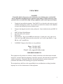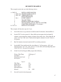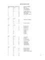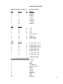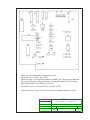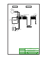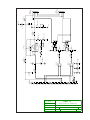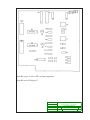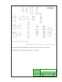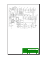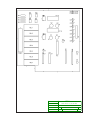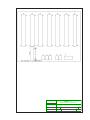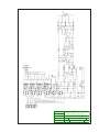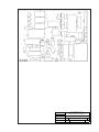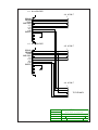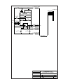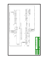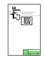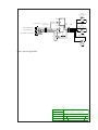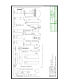
1
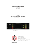
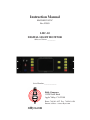
Instruction Manual
MANLMC10070C
Rev. F0805
LMC-20
DIGITAL LIGHT MONITOR
Software Version _________
Serial Number:______________
Eddy Company
13590 Niabi Road
Apple Valley, CA 92308
Phone: 760-961-8457 Fax: 760-961-8458
Internet address: www.eddyco.com
TABLE OF CONTENTS
GENERAL INFORMATION:
Basic description ………….…………………...………………...….
Warranty ……………………………….………………………..….
Unpacking/User Responsibility ………………………………..……
Initial Start-up ……………...……………………………...………..
1
2
3
4
DESCRIPTION AND SPECIFICATIONS:
Front Panel ………………………….…………………...………….
Specifications ……………..…………………………...……………
5
7
INSTALLATION:
Operator Safety ……………….………………...…………………..
Rear Panel Installation …………………………………………..…
8
10
OPERATION:
Start-up Menu ……………………………………….……………...
Set Clock ……………………………………………………………
Maintenance ........ ……..……………….…..…………….....……….
Create a New Program ………………...………………...………….
Material File Mode ………………..……………………..…………
Suggested Material I/O List …………………..…………...………..
I/O Interface …………….………………………………...………...
Run Mode-Warm Chip Changer ……….………... ………………....
Run Mode-Setting Outputs ……………………………………..…..
Run Mode-Changing Chips ……………...…………………..……..
Run Mode-Setting Mono ……………….……………………..……
Run Mode-Setting Gain ……………………………………...……..
Run Mode-Run Screen ……………...…………………..……….....
Run/Set-up Example ……………………………………………......
12
15
16
21
25
29
30
31
32
33
34
35
36
37
TABLES AND INFORMATION:
EDDY-20 Bus List ............................................................................
38
LMC-20- Rate Controller Interface .......................................................
LMC-20 Terminal Port Command & Data Protocol .............................
41
43
ENGINEERING DRAWINGS
Complete Assembly ………………………………………...……....
Interconnect Schematic SCHLMC10070C ………………...……....
Monochromator Control SCHLMC10060D .……………..………..
Monochromator Control LMC10ASY060D …………..……..…….
Monochromator SCHLMC101MR05 ……...…………..…………..
Chip Changer SCHLMC10061D ………………...………..…….…
Chip Changer LMC10ASY061F …………..……………….…..….
Chip Changer CC-34 DWGCC3400005 …………………...….…...
Amplifier and Demodulator SCHLMC10062F ………….………...
Amplifier and Demodulator LMC10ASY062F …………………....
Source Regulator SCHLMC10063E ………..………………...……
Source Regulator PCBLMC10063E …………...….……………….
BUS 10 I/O Board SCHBUS10064F ……..……...………….……..
BUS I/O Board ASYBUSI/O64F ….………………………..……..
BUS Board BUS10ASY066D ….……….……………….………...
Power Supply SCHLMC10068C …...…………..……………….…
Power Supply LMC10ASY068C ………………..………………....
Detector Wiring SCHLMC10070 …....……………..……………...
SI Detector SCHLMC10072B ………….…………...……………..
I.R. Detector SCHLMC101CRO …..………...…….………………
PMT-101, PMT 102 . …………………………………………..…....
Light Source SCHLMC10A070 …...………………………………
Dual RS-232 CONNECT MOD. …………….………………….....
LMC-10 Computer Connect …………….……………………….....
LMC-10 To MDC 360 Interface ……..…………………………......
LMC-10 Signal Gate Modification………………………………......
LMC-10 EXTERNAL START/STOP Mod. ...………………....…..
Brain SCHBRAIN069Q …………... …………………………..….
Brain Board BRAINASY069Q ………………………...……….....
A
B
C
D
E
F
G
H
I
J
K
L
M
N
O
P
Q
R
S
T
U
V
W
X
Y
Z
AA
AB
AC
BASIC DESCRIPTION
The LMC-20 is designed to meet and exceed today’s critical optical coating standards.
Anything less than results that are precise and consistent from run to run could spell disaster
for your operation.
The LMC-20’s high resolution, backlit LCD screen provides you with comprehensive
data much like a stripchart recorder. It also displays your program, the layer running, material specifications, and Xtal monitor run parameters.
The LMC-20 integrates easily into existing systems. Installation is as easy as plugging in sub-components. The multiple RS-232 ports communicate with several popular
crystal deposition controllers, the XYC-20 programmable sweep, and the SC-20 system
controller. Together these can provide complete data to your PC with our EDDY Link
software.
Final thickness shut-offs are calculated to an accuracy of 0.1% of amplitude change.
Together with the SC-20 and XYC-20, the LCM-20 will offer you the ability to perform 40
different processes, providing precise control over the optical thickness of each layer. Each
coating design may contain up to 50 individual layers. The input and output characteristics
can be customized to create up to 99 different materials.
1
LIMITED WARRANTY
This LMC-20 Light Monitor is warranted against defects in materials and workmanship for a
period of one year from the date of shipment to the original purchaser. This warranty will be
void if the instrument is not properly operated under conditions of normal use and if normal
and accepted maintenance protocols are not performed.
Defects resulting from, or repairs necessitated by, improper installation, misuse, negligence,
accident or corrosion of the equipment or any cause other than defective materials or workmanship are not covered by this warranty. No other warranties are expressed or implied,
including but not limited to the implied warranties of merchantability and fitness for a particular purpose. EDDY Company is not liable for consequential damages resulting from the
use of its equipment.
Purchaser’s sole and exclusive remedy under the above warranty is limited to EDDY Company, at its option, repairing or replacing any item which proves to be defective during the
warranty period provided the item is returned to EDDY Company together with a written
statement of the problem encountered. Any such obligation on the sellers part is subject to
the following requirements: 1) defect must be promptly reported to the seller, 2) if so
advised by the seller, component must be returned to the seller, no later than seven (7) days
after the end of the warranty period, and 3) on examination by the seller the part or component must be found to comply with the above warranty. Any item claimed to be defective
during the warranty period must be returned to the builder with the transportation charges
prepaid. Return trip transportation charges will be paid by the purchaser. In the event that
the seller elects to refund the purchase price, the instrument shall be the property of the seller
and shall be promptly shipped back to the seller at the sellers expense. EDDY Company
reserves the sole right to determine whether service is covered by the warranty.
If there are any questions about any of the equipment, parts or service call EDDY Company.
For all repairs, whether or not they are covered by the warranty, call EDDY Company service
line or our Internet address.
Phone number: 760-961-8457
Internet: www.eddyco.com
If the equipment needs to be returned for any reason you will be given a Return Material
Authorization (RMA) number.
2
UNPACKING
DANGER
Potentially lethal voltages may exist in the unit, even with the power switched off.
Service should be attempted only by experienced personnel. Failure to observe safety
protocols that are standard for high voltage equipment could result in personal injury.
1.
Completely unpack the instrument. Your LMC-20 was released to the carrier in good
condition and properly packed. It is essential to examine the contents of the shipment
to ensure that no damage occurred during transit.
2.
a.
b.
c.
d.
Compare the shipped materials to the packing list. Items included with your LMC-20
are:
LMC-20 Digital Light Monitor.
Operation and service manual.
Power cord.
Installation kit: Two 14-pin AMP male connectors, 28 male pins, one 14-pin strain
relief, one 9-pin AMP connector with strain relief, and 1 each 6 amp SB fuse, 3 amp
SB fuse, and 2 amp SB fuse.
3.
Call EDDY Company first if there are any problems.
Phone: 760-961-8457
Fax: 760-961-8458
E-mail: [email protected]
USER RESPONSIBILITY
This equipment will perform in accordance with the instructions and information contained
in the user’s manual when the equipment is installed, operated, and maintained in compliance
with the instructions. Equipment should be checked periodically, routine maintenance
performed and broken or non-working parts replaced immediately.
The user/purchaser shall have sole responsibility for any malfunctions resulting from their
improper use or lack of maintenance of the equipment.
3
INITIAL STARTUP
1. Read the manual.
2. Connect all shipped parts.
3. After reading the manual, establish that all the connected instruments are working
properly.
4. Connect power, check that line cord matches the line voltage, and turn LMC-20 on.
5. The main menu will appear.
6. Adjust the brightness and contrast for optimum viewing.
4
FRONT PANEL (description)
Increase or Decrease the
Program, Layer or Chip Count
Brightness
Contrast
Power
Programming Switches
LCD Screen
Sequence Selection Switches
Moves Highlight
UP / DOWN
ENTER
PAGE
EXIT
Source ON / OFF
(Enables the Light Source)
Press this key with the Start up screen and the program and layer shown will
be initiated. It will process one layer. With other screens this key will commit
the entered value to memory.
This key will change the display or move between I/O ports.
Returns to start up or manual menu.
START
Starts selected program and layer in full automatic mode.
RESUME
This key will over-ride the out of temperature error and continue the run
process.
STOP
Used when the process is in progress (it will stop the coating process), also
used in different maintenance modes.
5
EXIT
SOURCE
ON OFF
Returns program to main menu.
Pressing once will turn on the source at low power. Pressing twice will turn
source to high. Pressing a third time will turn the source off.
6
LMC-20 LIGHT MONITOR SPECIFICATIONS
All inputs and outputs are optically isolated for noise immunity. Each I/O Port can be programmed individually, giving you a selection of programming choices. Six output ports may
be programmed for DC closure or five volts output, both of which can drive your opto isolators. The seventh output is isolated and capable of controlling up to 60 volts at 1 amp. The
inputs are user programmable to accept contact closure or standard TTL logic.
CABINET:
DISPLAY:
WEIGHT:
SHIPPING WEIGHT:
AC INPUT VOLTAGE RANGE:
Power:
250 VA
Fuse:
120V - 2 amp SB fuse.
Fuse:
240V - 1 amp SB fuse.
POWER OFF MEMORY LIFE:
I.R.DET.:
SOURCE POWER:
REAR CONNECTORS:
Chip changer:
Mono:
Det. A and B:
Source:
Digital I/O A and B:
Test:
Heater:
Source Lamp:
DATA PORTS RS 232:
Terminal:
Printer:
5” X 17.2” X 13.5” deep includes
mounted parts on back panel.
Fluorescent backlit LCD.
18 lbs
22 lbs
97 TO 245 VAC. 50/60 Hz
120 months
+ 47.5 V.D.C. + - .02%
- 47.5 V.D.C. + - .02%
10.5/11.5 VDC regulated to + - .01%.
14 pin Twistlock
14 pin Twistlock
14 pin Twistlock
14 pin Twistlock
14 Pin Twistlock
LED
3 amp SB Fuse
6 amp SB Fuse
4800 baud (8,N,1)
Not enabled with V 6.2 or higher
software.
Xtal.:
MAXTEK MDC-360
SYCON
INFICON IC5
XYC-20:
9600 baud (8,N,1)
300 baud (8,N,1)
9600 baud (8,N,1)
Not enabled with V 6.2 or higher
software
7
OPERATOR SAFETY
DANGER:
Potentially lethal voltages may exist within this unit, even with the power shut off. Only
qualified personnel should attempt service. Failure to observe all safety precautions may
result in personal injury.
Observe the following precautions when servicing this instrument because of the potential
high voltage.
1.
Make sure HIGH VOLTAGE WARNING signs are posted in the service
area.
2.
Remove rings, watches, bracelets, and any other metal jewelry before
working around high voltage.
3.
DO NOT WORK ALONE.
4.
Be sure all equipment is connected to a power source that has the correct
polarity and grounding, as prescribed by the local electrical codes.
5.
Before servicing equipment be sure it is switched off at the main power switch. This
switch should have a lock out feature.
6.
Use a grounding hook to discharge any electrical parts that hold a lethal voltage after
shutoff. Be sure these parts are discharged before attempting any repairs.
7.
Do not touch any high voltage leads unless the power is off and a grounding
hook is connected to the parts being serviced.
8.
This instruments high-voltage components are equipped with electrical
interlocks to protect personnel from injury. DO NOT ATTEMPT TO DEFEAT,
OVERRIDE, OR BYPASS THESE PROTECTIVE DEVICES.
9.
Never leave loose ends on high voltage devices.
8
Health Hazard
The nature, as well as the form, of the condensates deposited on the tank walls and the
materials used in the coating process can pose health hazards. Some precaustions to take
include the following:
1.
To prevent inhaling the fine particles and prevent damage to the lungs, wear a
protective respirator mask that has been approved for this use by the National
Institute for Occupational Safety.
2.
Some of these materials are toxic. Inhaling them could prove to be deadly.
Be sure to know the toxic qualities of each material being worked with.
3.
Certain materials can cause flash fires when exposed to oxygen. (Example:
Titanium). When opening the chamber door after running a process use
extreme caution.
9
REAR PANEL-INSTALLATION
CHIP CHANGER:
MONO.:
DET. A and B:
SOURCE:
Connects to chip changer.
Connects to the monochromator.
Connects to the light detector.
Connects to the light source.
I/O PORTS A and B: Each Digital I/O Port has 7 isolated selectable outputs and 4 isolated
selectable inputs. Each port can be easily configured to communicate with the XYC-20 and
any standard opto isolator.
TERMINAL PORT: This port allows you to communicate with the EDDYLog and
EDDYLink software installed on a PC compatible computer. This will allow complete
memory upload and download and complete data logging. This port may be connected to a
PC with a terminal port program, configured for 4800 baud.
PRINTER: Not enabled by our V 6.2 or higher software.
XTAL: This standard RS-232 port is configured for Sycon (set to 300 baud), Maxtek MDC360 (set to 9600 baud), Inficon IC5 (set to 9600 baud). This port is used to select the material and initiate and terminate the coating process at the appropriate optical thickness or
designated physical thickness.
XYC-20: Not enabled by our V 6.2 or higher software.
10
REAR PANEL
DANGER
Potentially lethal voltages may exist within this unit, even with the power shut off. Only
qualified personnel should attempt to service this unit. Failure to observe all safety precautions may result in personal injury.
POWER INPUT and FUSE HOLDER:
The LMC-20 can be configured to use either 120 V ac or 240 V ac. The voltage
selected is controlled by the CORCOM power card which is installed in the slot below the
fuse holder. To remove the card use a pair of needle nosed pliers and pull out. To configure
for 120 volts turn card so the 120 is right side up and facing you. For 240 volts turn card over
and turn so 240 is right side up and facing you. Insert card into slot. Make sure the fuse is
the right one for the voltage selected. 120 volts requires the 2 amp SB fuse and 240 volts
requires the 1 amp SB fuse.
11
STARTUP MENU
When first powered up the following screen will display. This is the default screen
-
LIGHT
MONITOR
MAIN
PROGRAM
#
MENU
-
: 38
LAYER # : 47
REMOTE START
CREATE
PROGRAM
MODIFY
PROGRAM
CHIP
COUNT
: 18
MAINTENANCE
MATERIAL
LMC-20
#1298X31
FILE
V 7.x
EDDY
CO
Read all of the following sections before changing or initiating any
selected line.
Moves highlight up (will roll over) to select a line.
Moves highlight down (will roll over) to select a line.
START
Caution: Pressing this button will start the selected program with the
selected layer, in full automatic mode, from any highlighted line.
The following is a brief description of the options on this screen:
REMOTE START:
This allows the LMC-20 to start the process, without an
operator present, once it gets the correct signal from the SC-20.
It will initiate the program starting at the displayed layer on the
screen. Because the power is available to all systems, it is not
recommended that this option be used less someone is on hand to
monitor all the systems, and ensure that no problems occur.
12
CREATE PROGRAM:
This allows the creation of a new program. There are 40 programs
available, each with up to 50 layers. Always check the Modify
Program screen to ensure you are not overwriting an existing program.
MODIFY PROGRAM:
This allows the modification of existing programs.
CHIP COUNT:
This indicates the number of the chips in the chip changer at the
start of the process. (Nominally 35) As the run proceeds and the
chips are dropped this amount will go down. Since a running total
of the remaining chips is kept, if this amount is not updated with
each run the LMC-20 will use the last figure, which may not be
enough chips to finish the run. This value equals the amount of
chips needed plus two. Example: 20 needed for run, add 2, for a
total of 22 chips.
MAINTENANCE:
The maintenance option allows the operator to individually operate
each function to locate and isolate troubles.
MATERIAL FILE:
This option allows the operator to program the output and input
pattern to coincide with patterns from other devices.
With either the Program, Layer, or Chip Count line highlighted the following keys are used:
INC +
Increases the highlighted selection.
DEC -
Decreases the highlighted selection.
ENTER
Starts a single layer run from highlighted program and layer;
stops at the completion of the selected layer.
START
Will start selected program and layer in full automatic mode.
13
With any of the following lines highlighted: Create Program, Modify Program, Maintenance,
or Material File, these keys have the following functions.
ENTER
PAGE
EXIT
START
Will enter the selected option.
Will go to the next page in the selected option.
If pressed from the selected option will go to the Main menu, if
pressed from a sub-screen will go to the selected option.
Will start selected program and layer in full automatic mode.
Use the up and down ARROWS to scroll through the selections and the INCR + or DECR –
to increase or decrease values or enable or disable functions.
The + or – in front of a selection indicates if that selection is enabled or disabled.
Highlight the MAINTENANCE line and press ENTER. Use the INCR+ and DECR – keys
to highlight SET CLOCK. Press ENTER to show the SET CLOCK screen.
14
SET CLOCK
This option allows the setting of the internal clock to correspond with the other devices
- SET CLOCK -
18 =
SECONDS
37 = MINUTES
17 =
HOURS
05 =
DATE
05 =
MONTH
9 2 = YEAR
LMC-20
V7.x
EDDY CO.
Moves highlight up (will roll over) to select line.
Moves highlight down (will roll over) to select line.
Values that are highlighted can be changed.
INC +
Will increase selected value.
DEC -
Will decrease selected value.
Press EXIT to return to the Maintenance screen.
15
MAINTENANCE
The Maintenance menu allows manual operation of each function for testing and diagnostic
actions or to locate and isolate any problem encountered
-
MANUAL
OPERATION
/
PAGE
OUTPUTS
-
1
-
INPUTS
MATERIAL I/O
- SET CLOCK
-
GAIN 3 12400
- TIME CONSTANT
-
DETECTOR
-
LM ZERO FLAG
-
MONO SET 5 00
-
BLOCKING FILTER
LMC-20
LM VALUE 4 30
LAMP
=
5.0
AMPS
A
V7.x
EDDY CO.
The + and the – in front of an item indicates enabled or disabled.
Moves highlight up (will roll over) to select line.
Moves highlight down (will roll over) to select line.
INC +
Will increase the highlighted value.
DEC -
Will decrease the highlighted value.
ENTER
Will activate the highlighted line.
MATERIAL I/O:
Press ENTER to display I/O values. The operator may change
the output bits status (enabled, disabled) and read the status of
the input bits.
16
SET CLOCK:
Press ENTER to set the internal clock to the correct time.
LM SIG:
The INCR + or DECR – key changes the numerical value. Pressing the
ENTER key starts auto gain change. The unit will adjust the gain to
give a signal within 10% of the entered value.
LM GAIN:
Set the gain with the INCR + or DECR -key. Observe the proportional
reading change on the LM Value.
TIME CONSTANT:
Lower values give faster response, and higher values give less noise.
Try 3 to start.
DETECTOR:
Changes input port from A to B.
LM ZERO FLAG:
Applies voltage for mechanical shutter when appropriate.
MONO SET:
Sets the value of the monochromator from 350nm to 850nm.
BLOCKING FILTER:
Enables and disables the blocking filter on the light source.
LM VALUE:
This is a display of the light signal with a range of 0 to 1000.
SOURCE
ON OFF
PAGE
EXIT
Cycles the light source lamp through off - 95% - 100% - off.
Press to change displayed page.
Returns the program to the startup menu.
17
MATERIAL I/O
- MATERIAL I/O PORT A OUTPUTS
INPUTS
-PIN 1
- P I N 10 OFF
-PIN 2
- P I N 11 OFF
-PIN 3
- P I N 12 OFF
-PIN 4
- P I N 13 OFF
-PIN 5
-PIN 6
-PIN 8 / 9
LMC-20
V7.x
EDDY CO.
Note: The inputs are read in real time.
Moves highlight up (will roll over) to select a line.
Moves highlight down (will roll over) to select a line.
PAGE
Cycles between I/O ports A and B.
INC +
Will enable output on selected pin outputs.
DEC -
Will disable output on selected pin outputs.
EXIT
Returns to the manual operation menu.
18
MAINTENANCE
From Material I/O press EXIT to return to Manual Operation page 1, then press PAGE to go
to Manual Operation page 2.
-
MANUAL OPERATION / PAGE 2 -
OUTPUTS
INPUTS
-CHIPHEATER
CHIP TEMP = 20
-CHIPMOTOR
CHANGER SWITCH
CHIP DROP 1 CYCLE
TEMP BAND
MDC STOP
:
50
: ON
GRAPH DELAY
:
10
MDC 3 6 0 : ON
MIN ZERO : 10
MAX GAIN
10000000
LMC-20
V7.x
EDDY CO.
Moves highlight up (will roll over) to select a line.
Moves highlight down (will roll over) to select a line.
INC +
This will enable, disable or increase the values on the selected line.
DEC -
This will enable, disable or decrease the value on the selected line.
The + and – at the beginning of the highlighted line indicates if cycle is enabled or disabled.
CHIP HEATER:
INCR + and DECR – enables the heater power. (Make sure the fuse is
removed or the heater is in vacuum before starting the heater).
19
CHIP MOTOR:
Pressing INCR + will cause the motor to continuously drop chips until
DECR – is pressed.
CHIP DROP CYCLE:
Pressing ENTER will cause the chip changer to operate for one cycle.
TEMP BAND:
Sets the maximum allowable limit for witness chip temperature
(+ or -).
SYCON,MDC 360, IC-5, STOP:
Will stop the process if communication failure is detected.
GRAPH DELAY:
This value is the amount of seconds between redraws on the data
logging screen (Suggested time: 15 seconds). This has no effect on the
response time of the instrument.
SYCON
MDC-360:
IC/5
This is enabled to allow the instruments to talk to each other.
MIN ZERO:
Maximum allowable signal seen by the detector with the light source
off. ( 25 suggested)
MAX GAIN:
The maximum allowable gain for the process. Set this value to about
5 million higher than your highest acheived gain. If it should need
more gain than this then it might be an indication there is an alignment
problem or an obstruction in your light path.
CHIP TEMPERATURE:
Temperature at the chips in degree C.
CHANGER SWITCH:
The status of the chip changer, end of cycle, switch.
20
CREATE A NEW PROGRAM
There are 40 programs available, each with up to 50 layers. The values set will affect all
layers of the program entered. The screen starts with a default value for each layer. Once
you start entering the values for a program you cannot go backwards. To save the program
you must cycle through the entire list on both pages. If you need to change anything go int
MODIFY PROGRAM from the main menu.
CAUTION:
Before using the Create Program check the program number you will use with the Modify
Program screen to ensure you do not overwright an existing program.
PROGRAM
# :
WITNESS
1
LAYER # :
CHIP
OVERSHOOT
:
TEMPERATURE
20 C
10%
NOISE
REJECTION
LEVEL
#
LAYERS
2
OF
:
1
:
:
10
When this screen first comes up it will display only the Witness Chip Temperature line. After
the correct value is entered or verified pressing ENTER will activate the next line.
ENTER
Use this key to activate the next line after entering the values on the
current line.
INC +
Will increase the highlighted value.
DEC -
Will decrease the highlighted value.
WITNESS CHIP TEMPERATURE:
This sets the target temperature for the chip heater. This temperature
is usually the same as the substrate temperature.
21
OVERSHOOT:
Nominally 4%, this sets the amount of signal change required to
determine a quarter wave transition.
NOISE REJECTION LEVEL:
20 times the noise rejection level is the minimum change in signal
necessary for the computer to recognize that the signal is going
through the maximum or minimums set. Typically set for 5.
Example: Set noise to 5, and set initial signal intensity to 100. The
signal will have to increase from 100 to greater than 200 for the
computer to recognize a quarter wave.
# OF LAYERS:
Total amount of layers in this coating. Pressing the INCR + key will
increase the layer count, and the DECR- key will decrease the layer
count. After pressing enter (# of layers) the individual layer parameter
screen(s) will then sequence.
CREATING A PROGRAM:
There are three standard ways to enter a layer. The following three
diagrams will show you.
PROGRAM
#
LAYER
1
CHIP DROP
QUARTER
INITIAL
: 1
: YES
WAVES
SIGNAL
MONOCHROMATOR
MATERIAL
#
:
:
: 2.22
8 00
:
5 50
2 0 SiO2
This screen shows a basic layer consisting of a witness chip change, 2.22 quarter waves,
initial signal of 800, monochromator of 550nm, and material 20 (SiO2). When you first enter
a layer screen the only option you see is Chip Drop. You use the INC+ and DEC - buttons to
change the values. Once a value is set you press ENTER to see the next parameter. NOTE:
No changes will be saved until you press ENTER after selecting your material. Exiting
before will result in all changes for that layer being lost.
22
PROGRAM
#
LAYER
1
CHIP DROP
:
2 30
SIGNAL
:
MONOCHROMATOR
MATERIAL
: 1
: YES
THICKNESS
INITIAL
#
:
8 00
:
5 50
2 0 SiO2
This screen is similar to the last screen except instead of quarter waves we are using physical
thickness (in angstroms). To use a physical thickness run the value for the quarter waves
down to 0.00. Now press ENTER and the line will now read thickness: 0. In the example
above the thickness is set to 230 angstroms. To change back to quarter waves just run the
thickness back to 0 and press ENTER and you will go back to quarter waves.
PROGRAM
#
1
LAYER
CHIP DROP
QUARTER
INITIAL
WAVES
1/4
: .9
WAVE
INTENSITY
SIGNAL
MONOCHROMATOR
MATERIAL
: 1
: YES
FRACTIONAL
CUTOFF
#
:
:
:
6 50
9 00
:
5 50
2 0 SiO2
Finally, if you enter in anything less than a quarter wave you will be able to do a fractional
quarter wave. The screen will show Fractional 1/4 Wave and below it there will be a line
called Cutoff Intensity. Here you put in the intensity value that you want the layer to stop at.
For example if you know that one quarter wave will roughly go from 900 to 400 and you
want half of a quarter wave then you put in 650.
23
CHIP DROP: “YES” to start with a clean chip.
QUARTER WAVES:
INC +
Increases the value of quarter waves.
DEC -
Decreases the value of quarter waves.
Select from 1 to 99.9. Use INCR+ OR DECR – to select the values.
Press ENTER to go to next parameter.
FRACTIONAL 1/4 WAVE
CUTOFF INTENSITY:
This line is displayed when less than one quarter (1/4) wave is seected.
The cutoff intensity values are from 10-999 representing 0-100%
reflection at the gain set. If 0.00 is selected and ENTER pressed, the
physical thicknes paramters will display. Select 0 from the physical
thickness parameters, PRESS ENTER and the program will return to
quarter waves. Press ENTER to go to next parameter.
INITIAL SIGNAL: (In reflectance monitoring mode)
This is set high for low index materials and low for high index
materials. For example Ti02 start at 100, and Si02 start at 900.
Press Enter to go to next parameter.
MONOCHROMATOR:
Values for the monochromator range from 350nm to 850nm in a 1:1
ratio. For greater wavlengths this value must be multiplied by the
grating calibration factor. (2:1), (3:1), (4:1).
MATERIAL:
Material range: 1 to 99. This relates to the RS-232 output signals
controlling the xtal monitor, through the I/O ports. The tens digit tells
the xtal monitor which material or film to run. Selecting material 20
will send a start signal to the crystal monitor requesting material or
film 2 and create an output pattern matching material 20.
NOTE: Some rate controllers refer to materials differently than
others. The Sycon STC-200 calls them Films. The Maxtek MDC-360
and Inficon I/C-5 call them Materials.
24
MATERIAL FILE MODE
From the Main Menu select Material File and press ENTER.
DESCRIPTION : SiO2
MATERIAL : 20
OUTPUT
A
OUTPUT B
INPUT A
INPUT B
1
OFF
OFF
OFF
OFF
1
2
OFF
ON
OFF
OFF
2
3
OFF
OFF
OFF
OFF
3
4
OFF
OFF
OFF
OFF
4
5
OFF
OFF
5
6
OFF
OFF
6
7
OFF
OFF
7
E GUN VOLTAGE :
LMC-2 0
ENTER
6 K.V.
V7. 2
THE EDDY CO.
Pressing this key will cycle the highlighted options through
MATERIAL, DESCRIPTION, OUTPUT A, OUTPUT B, INPUT A,
INPUT B, and E-GUN VOLTAGE.
MATERIAL:
INC +
This increases the highlighted value.
DEC -
This decreases the highlighted value
DESCRIPTION:
Moves selected sub-field left. Selects 1 of 8 possible fields to modify.
Moves selected sub-field right. Selects 1 of 8 possible fields to modify.
25
INC +
This will select the ASCI characters.
DEC -
This will select the ASCI characters.
The description field is composed of up to 8 sub fields. Press INCR + or DECR – to select
the character displayed in the highlighted position. All standard keyboard characters are
available to be used for the description.
Character set available in description field (In order of appearance):
! “ # % $ ’ ( ) * + , - . / 0-9 : ; < = > ? @ A-Z [ Y ] ^ _ ‘ a-z {
}Æ ¨
OUTPUT A-B and INPUT A-B:
Scroll up to select field to modify.
Scroll down to select field to modofy.
INC +
Will enable the output.
DEC -
Will disable the output.
The outputs of the 2 output ports may be set to match any control pattern required to operate
other equipment or communicate with other components used in automatic coating processes
The input patterns must be set to match outputs from other equipment. Input B, 1-4 will
match Output B, 1-4, from the XYC-20. There are 16 different patterns. Each program has
its own unique pattern. When the input pattern is exactly matched for more than 1 second the
pattern will be run.
E-GUN VOLTAGE:
Voltage may be set from 0 to 10KV in 1KV increments. This is for
reference only.
NOTE: You must cycle through all the feilds and bring the highlight back to the Material #
before exiting for the changes to be stored to memory.
When done press EXIT to return to the Main Menu.
26
EXAMPLE:
From the main menu screen select the Material file.
When the screen is visible the material number will be highlighted. Use the INCR +
or DECR – keys to select the material number. When selecting the material number you
must keep in mind that the tens digit will determine which material is to be sent to the Xtal
monitor. For example: materials 10-19 will command material 1 on the Xtal monitor to be
used. The materials 20-29 will command material 2 to be used.
Press the ENTER key to go to the description field. The description field is composed
of up to eight characters. The ARROW key selects the position of the character being displayed, and the INCR + and DECR – keys toggle through the description. All standard
keyboard characters are available to be used for the description. Enter the description for
Aluminum Oxide, Al203, by pressing the INCR + and DECR – keys to select the ASCI
character “A”. Press the down ARROW key to move the field right and use the INCR + and
DECR – to select the ASCI character “l”. Continue until all the characters are entered.
Press the ENTER key to go to the top of each output or input column and the arrow
keys to move up or down the field. Use the INCR + and DECR – keys to enable or disable
the selected field.
The outputs of the two I/O ports may be set to match any control pattern required to
operate any other equipment or communicate with other components used in the automatic
coating process. Typically, Output B, 1-4 are used to communicate with Input B, 1-4 on the
XYC-20.
The input must be set to match outputs from other equipment. There are 16 different
combinations. Each program has its own unique description. When the descriptions are met
for more than 1 second the coating will run.
Once selections are made, press ENTER to scroll to the Material field. This action
will put the file into memory.
NOTE: Failure to go back to material feild prior to pressing EXIT may result in
changes not being saved.
EXIT
Press to return to the main menu.
27
LMC-20:
DESCRIPTION : SiO2
MATERIAL : 20
OUTPUT
A
OUTPUT B
INPUT A
INPUT B
1
OFF
OFF
OFF
OFF
1
2
OFF
ON
OFF
OFF
2
3
OFF
OFF
OFF
OFF
3
4
OFF
OFF
OFF
OFF
4
5
OFF
OFF
5
6
OFF
OFF
6
7
OFF
OFF
7
E GUN VOLTAGE :
LMC-2 0
6 K.V.
V7. 2
THE EDDY CO.
Patterns must match (over 99 possible matches)
each program needs to have its own unique pattern
Connect bits 1-4 Output B to bits 1-4 Input B
XYC-20:
Connect bits 1-4 Output A to bits 1-4 Input A.
DESCRIPTION : SiO2
MATERIAL : 20
OUTPUT
A
OUTPUT B
INPUT A
INPUT B
1
OFF
OFF
OFF
OFF
1
2
OFF
ON
OFF
OFF
2
3
OFF
OFF
OFF
OFF
3
4
OFF
OFF
OFF
OFF
4
5
OFF
OFF
5
6
OFF
OFF
6
7
OFF
OFF
7
E GUN VOLTAGE :
LMC-2 0
Output A 1-6 refer to
e-gun pockets 1-6
V7. 2
6 K.V.
THE EDDY CO.
Typical system interconnect.
Optional for increase beyond 15 matches.
28
SUGGESTED MATERIAL I/O LIST
(Please photocopy for each material)
MATERIAL: _________
DESCRIPTION: _____________________________________
OUTPUT A/TYPE
1.
2.
3.
4.
5.
6.
7.
USE
DESTINATION
OUTPUT B/TYPE
1.
2.
3.
4.
5.
6.
7.
INPUT A/TYPE
1.
2.
3.
4.
INPUT B/TYPE
1.
2.
3.
4.
E-GUN VOLTAGE:
29
I/O INTERFACE
(ASYBUS10064F)
DIGITAL I/O - A and B
Pin #
1
2
3
4
5
6
7
8
9
Signal
Output 1
Output 2
Output 3
Output 4
Output 5
Output 6
Common for outputs 1-6
Output 7 +
Output 7 -
Jumper PCBP4 installed from 1 to 2 will cause outputs 1 through 6 to source 5 VDC at 10
ma.
Jumper PCBP4 installed from 2 to 3 will cause outputs 1 through 6 to sink 500 ma at up to 60
VDC. Output 7 will sink up to 500 ma at up to 60 VDC.
Pin #
10
11
12
13
14
Signal
Input 1
Input 2
Input 3
Input 4
Common for inputs 1-4
Jumper PCBP1 installed from 1 to 2 will cause inputs 1 to 4 to respond to a contact closure.
Jumper PCBP1 installed from 2 to 3 will cause inputs 1 to 4 to respond to 5 VDC input with
a source current of 5 ma.
30
RUN MODE
Press START to enter the Run Mode.
WARMING
CHIP
CHANGER
SET
POINT : 1 0 0
CHIP
TEMP : 1 0 0
PRESS
RESUME
WHEN
READY
SET POINT: Target chip temperature for the selected run.
RUN MODE
CHIP TEMP: Actual chip temperature.
PRESS RESUME
WHEN READY:
Pressing RESUME will override the temperature window.
Note: This screen passes quickly and will only stop if parameters are out of bounds.
31
RUN MODE
SETTING MATERIAL OUTPUTS
WAITING FOR MATERIAL INPUTS
RUN
NUMBER
RUN
TIME :
LAYER
:
MATERIAL
:
1023
STANDBY
SIGNAL
1
MAXIMUM
: MGF2
MINIMUM
:
:
:
RUN NUMBER:
There is no user access to this number.
RUN TIME: Keeps a running total of time on the current run.
This screen will stay up for about 10 seconds. It displays until the correct I/O pattern
is met.
There is a 15 second delay after the input pattern is met before the coating program
continues.
32
RUN MODE
CHANGING
AFTER
RUN
NUMBER
RUN
TIME :
LAYER
:
MATERIAL
MANUAL
:1023
CHANGE
CHIP
PRESS
RESUME
STANDBY
SIGNAL
1
MAXIMUM
: MGF2
MINIMUM
:
:
:
CHANGING CHIP:
Displayed at the start of the chip changer motor.
AFTER MANUAL CHANGE PRESS RESUME:
Displayed when the time required to change the chip is exceeded.
If there is a chip change, the screen will display a time count up. Up to
12 seconds is normal. If there is more than 15-17 seconds, the changer
has jammed. It will also display when the chip changer is not
connected to the LMC-20.
RESUME:
Continues the run process.
33
RUN MODE
SETTING
MONOCHROMATOR
WAVE LENGTH
POSITIONING
AFTER MANUAL
RUN
NUMBER
: 102 3
:
5 00
ERROR
SETTING
PRESS
RESUME
STANDBY
RUN TIME :
SIGNAL
:
LAYER :
1
MAXIMUM
MATERIAL
: MGF2
MINIMUM
:
:
SETTING MONOCHROMATOR:
The servo is adjusting the monochromator to the programmed
wavelength.
POSITIONING ERROR:
This message indicates the monochromator is not connected or is
not working properly.
1.
Confirm that all connections are good.
2.
If all the connections are good, you have the option to
operate manually or send the unit for service. For
manual operation disengage the motor drive and
manually adjust the monochromater. Caution: Failure
to disengage the motor will result in motor gear train
damage.
3. Press RESUME to continue the program.
34
RUN MODE
SETTING GAIN
GAIN
:
6137000
LM VALUE :
RUN
NUMBER
RUN
TIME :
LAYER
:
MATERIAL
: 1023
800
STANDBY
SIGNAL
1
MAXIMUM
: MGF2
MINIMUM
SETTING GAIN:
:
:
:
The gain is being varied from 1 to 1.676 x 10⁹.
MAXIMUM GAIN: This display indicates lack of expected optical signal.
NOTE: Calculations are based on the gain value. LM
Value (0-1000) is used for operator interface purposes.
(Recommended: 1,000,000 gain should give approximately
100 signal value at monochromator setting of 600nm). Also
see page 19.
Some possible causes of a maximum gain error are:
1. Chip fell into light path or some other obstruction.
2. A misalignment problem.
3. Out of witness chips.
35
RUN SCREEN
RUN
NUMBER
RUN
TIME :0 8 :1 2
PGM
: 1
MATERIAL
:
/
:
3 RD
102 3
LAYER
: 1
MGF2
1/ 4
WAVE
SIGNAL
:
79 0
MAXIMUM
:
8 40
MINIMUM
:
2 59
RUN NUMBER:
This number increases each time a run is started. There is
no method for the user to modify this number.
RUN TIME: This is the amount of time this coating program has been running.
PGM:
This is the program selected.
LAYER:
The layer being coated is displayed.
MATERIAL: The material being used to coat the substrate. Will be blank if not
entered into the material file description feild.
COATING:
Indicates program status. Will display current thickness in angstroms
when physical thickness has been selected for the layer. Also shows
coating complete.
SIGNAL:
Intensity reading.
MAXIMUM: The value of the last peak detected.
MINIMUM: The value of the last valley detected.
36
RUN/SETUP EXAMPLE
This example involves the use of the following devices:
A. LMC-20
1. LMC-10A
2. LMC-10C
3.
4. PS-4
5.
6.
7.
8.
B. XYC-20
DIGITAL LIGHT MONITOR
CHOPPED LIGHT SOURCE
VISIBLE DETECTOR
MONOCHROMATOR
POCKET SELECT
TWO SHUTTERS
EXTERNAL PRESURE CONTROL
XTAL MONITOR (SYCON, INFICON, MAXTEK)
COMPUTER SOFTWARE (V 6.2 or higher)
DIGITAL E-GUN SWEEP
This example will show the steps for 1 layer.
A.
Load all the necessary parameters for Si02 into the Xtal monitor. (Material/Film 2)
B.
On the XYC-20 select pattern 20. Enter Si02 into description field and from I/O
columns assign appropriate outputs in Output A for pocket select. Select Input B and
select 1 off, 2 on, 3 off, 4 off. Confirm that in Input A column all are off. Load in a
9x3 pattern.
C.
Run Xtal monitor in manual mode for Si02 to confirm parameters.
D.
On the LMC-20 in the Material file select Material - 20, Description – Si02, and
Output B select 1 off, 2 on, 3 off, 4 off, 5,6,7, all off. (This will match Input B pattern
20 on XYC-20). See page 28 for diagram.
E.
In the Create New Program Mode program the following:
Witness Chip Temp.
Overshoot
Noise Rejection Level
# Of Layers
150 degrees C
4%
8
1
Layer 1
Chip Drop
Quarter Wave
Initial Signal
Monochromator
Material
F.
Yes
2.00
900
550
20
Si02
Start will start the selected program.
37
EDDY-20 BUS LIST
BRAIN BOARD IC SIGNALS
A/D
IC-26
J-1
0
26
50
1
27
20
2
28
51
3
1
21
4
2
52
5
3
22
6
4
53
7
5
23
D/A
0
1
2
3
IC-28
2
1
20
19
BIT
0
1
2
3
4
5
6
7
IC-18
4
3
2
1
37
36
35
34
BIT
0
1
2
3
4
5
6
7
BIT
0
1
2
3
4
5
6
7
SIGNAL NAMES
LMC-20
DET. SIGNAL
LAMP TEST HI
LAMP TEST LO
MOTOR POS. SWI.
CHIP TEMP.
MONO POS. INPUT
24
55
25
56
MOTOR CONTROL
3
33
2
32
I/O BD AD 0
I/O BD AD 1
I/O BD AD 2
I/O BD AD 3
LAMP 1
LAMP 2
LAMP 3
LAMP 4
IC-18
18
19
20
21
22
23
24
25
38
8
39
9
40
10
41
11
GAIN SET
CLOCK
LOAD GAIN
LOAD 20 GAIN
LAMP LOW
CHIP HEAT
LAMP HIGH
CHIP MOTOR
IC-18
14
15
16
17
13
12
11
10
36
6
37
7
5
35
4
34
I/O BD DATA 4
I/O BD DATA 5
I/O BD DATA 6
BITS 3-7 NOT USED
E GUN VOLTS
38
EDDY-20 BUS LIST
BRAIN BOARD IC SIGNALS
BIT
IC-17
J-1
0
4
1
3
2
2
3
1
4
37
5
36
6
35
7
34
SIGNAL NAMES
LMC-20
LAMP 5
LAMP 6
LAMP 7
LAMP 8
LAMP 9
LAMP 10
LAMP 11
LAMP 12
BIT
0
1
2
3
4
5
6
7
IC-17
18
19
20
21
22
23
24
25
15
45
14
44
13
43
12
42
.5 TC
1 TC
5 TC
2 TC
BLKS FILTER
DET. A/B
ZERO FLAG
X100 GAIN
BIT
0
1
2
3
4
5
6
7
IC-17
14
15
16
17
13
12
11
10
19
49
18
48
17
47
16
46
I/O BD DATA 0 OUT
I/O BD DATA 1 OUT
I/O BD DATA 2 OUT
i/O BD DATA 3 OUT
I/O BD DATA 0 IN
I/O BD DATA 1 IN
I/O BD DATA 2 IN
I/O BD DATA 3 IN
FRONT PANEL
IC-33 BRAIN BOARD DECODER
0
1
2
3
4
5
6
7
8
9
10
11
ENTER
PAGE
EXIT
UP ARROW
DOWN ARROW
INCR +
DECR START
RESUME
STOP
EDIT
SOURCE
39
EDDY-20 BUS LIST
POWER DISTRIBUTION EDDY-10 BUS
BUS
J-1
LMC-20
31
1
61
30
60
29
59
28
57
GROUND
GROUND
5
5
15
-15
24
I/O ENABLE
40
LMC20 / MDC 360 INTERFACE
HARDWARE
The LMC-20 and MDC 360 physically connect as shown in tables 1 and 2. The RS-232 port
connection allows the LMC-20 to command the MDC 360 to use the programmed materials
and thickness’, and to start the coating process. The parallel discrete I/O port connection
allows the LMC-20 to hold the MDC 360 in a soak state and to terminate a deposit when the
programmed number of quarter waves have been completed, or the coating is manual terminated.
The RS-232 communication speed is fixed at 9600 baud / 8 data / no parity / 1 stop. There
are no adjustments or settings for this port in the MDC 360. In the LMC-20, turn on the
MDC communications by accessing the control switch under the maintenance menu second
page.
The parallel connection is fixed in the LMC-20 to Port A / Bit 7. This bit is not available for
programmed material I/O. The MDC 360 however must be configured for the control function to work. The actual bit used within the MDC 360 does not matter. It can be assigned to
any available bit. For this example input bit 7 is used.
CONFIGURING THE MDC 360
Refer to the MDC 360 operators manual section 4.4.2. “PROGRAM INPUTS”. Follow the
procedures covered there to assign a logical name to input #7. Use “COAT” for this example. The name “COAT” will be used in all subsequent referrals to input #7.
Next configure the MDC 360 to take the action “Hold in State” when the controller is in the
“Soak Hold” state and the input bit “COAT” is false. Refer to section 4.4.4 “PROGRAM
ACTIONS”. The first action to program is “Hold in State”. Select the “Hold in State” action
from the table and then enter a condition string to specify when to take this action. Refer to
section 4.4.3.1 “ENTERING A CONDITION STRING”. The first element of the condition
string is the “Soak Hold” state. The second element in the condition string is the input bit
“COAT”. The condition string should look like this: Soak Hold & (!COAT). This will cause
the controller to hold in state when the “Soak Hold” state is reached and the “COAT” bit is
false.
Next configure the MDC 360 to take the action “Terminate Deposit” when the controller is in
“Deposit 1” state and the “COAT” bit is false. Again refer to sections 4.4.4 and 4.4.3.1 to
configure the controller. The condition string should look like this: Deposit 1 &(!COAT).
This will cause the controller to terminate the deposit when the “Deposit 1” state is reached
and the “COAT” bit is false.
41
PROGRAMMING MATERIALS
The LMC-20 uses material numbers from 1 through 99. The 10’s digit of the LMC-20 material number corresponds to the 1’s digit of the MDC 360’s material number. This allows the
LMC-20 to be programmed to use the same MDC 360 material, but vary the pocket or
pattern outputs used by the E-gun controller. For example the material LMC-20 material #31
would use MDC material #3 and the 1st E-gun pocket. While material #33 would still use the
MDC material #3 but the 3rd E-gun pocket.
LMC-20 materials 1 through 9 correspond to MDC materials 11 through 19. MDC materials
10 and 20 through 31 are not accessible through the LMC-20.
OPERATION
When the LMC-20 starts a coating program it sends an “ABORT” command followed by a
“RESET” command to the MDC 360. The MDC 360 will beep and the front panel indicators
will change state to indicate the commands. This is a sure indication that the RS-232 interface is configured and working properly.
The LMC-20 then does various housekeeping functions like printing the program, warming
the chip changer etc. When the LMC-20 displays the message “SETTING MATERIAL
OUTPUTS, WAITING FOR MATERIAL INPUTS”, one of the inputs the LMC-20 is waiting
for is the MDC 360 to report that it is in the “Process ready” or “Process complete” state.
Until the MDC reports either of these two states the LMC-20 will stay in this condition.
When the material inputs have been satisfied the LMC-20 sends the new material for this
program / layer to the MDC 360. The LMC-20 always uses MDC process #1 and MDC layer
#1. The LMC-20 always names the process “LMC-20 PP/LL”. Where PP = LMC-20 program # and LL = LMC-20 layer #. This is displayed in the process name position on the
MDC 360’s LCD screen. Next the LMC-20 sends the start command to the MDC 360. The
LMC-20 must rely on the proper configuration of the “COAT” bit input to the MDC 360 for
the process to stay synchronized.
The LMC-20 then adjusts the monochromator and the detector gain (if needed). The LMC-20
then starts the layer by turning the “COAT” bit on (0 volts) and begins monitoring the quarter
wave (or thickness) readings. If coating by quarter waves the LMC20 determines when the
layer is complete, if coating to a thickness the MDC 360 determines when the layer is complete. In either case, at the end of the layer the “COAT” bit is turned off (open / 5 volts) and
the process is repeated for the next layer. If all layers are complete both instruments will beep
until a front panel key is pressed.
42
LMC20 Terminal Port Command & Data Protocol
Communications settings: 4800 baud, 8 data bits, 1 stop bit, and no parity.
General
All of the inputs and most of the outputs are printable ASCII characters. The instrument
responds to single character commands. No terminators or checksums are required. The
operator can invoke the commands and observe the outputs by connecting a “dumb terminal”
program directly to the instrument.
Remote Start
With the instrument at the main menu (start up condition), the desired program and starting
layer selected, and the cursor highlighting “REMOTE START” an ASCII 7 received via the
terminal port will start the coating process. This is identical to pressing the start key.
Remote Stop
During the coating process if the instrument receives any ASCII number between 1 and 6 the
coating will be halted. This is identical to pressing the stop key. At the end of a coating the
instrument will send “COATING COMPLETE” <cr><lf> about once every 2 seconds until
an operator presses a front panel key or until the instrument receives a remote stop command.
During the coating process if the instrument receives an ASCII H the crystal monitor will be
halted, but the LMC20 will remain in the coating state. The operator must restart the crystal
monitor to resume the coating.
Data logging outputs
The instrument outputs various program, status, and data values during the coating process.
Each line is terminated with carriage return and line feed characters. Below is a typical
output from a 2-layer coating.
The instrument first lists the program that will be executed followed by an XON (11H)
character. After the instrument programs the crystal monitor, adjusts the monochromator, and
sets the signal gain it sends “LAYER STARTED”, followed by the date and time.
As the coating proceeds the instrument outputs single lines of coating data at the graph delay
interval. A data line consists of:
The light level value followed by a graphed representation of that value. The graph has a
resolution of 70 points with a full-scale value of 1365. The light value graph is followed by
the crystal monitor power reading in percent and coating thickness in angstroms.
Peak and valley values are reported as they occur. Quarter waves and any fractions are
reported as the program values are attained. When a layer is complete the date and time are
reported along with the process data shown in the example.
43
When the “COATING COMPLETE” state is reached that message is reported every two
seconds until the operator presses a front panel key or a remote stop is received.
PROGRAM # 1
OVERSHOOT = 4 % NOISE LEVEL REJECTION = 5
WITNESS CHIP TEMPERATURE = 134
LAYER
1
2
# OF QWAVES INITIAL RDG
1
500
1
500
MATERIAL
10
20
MONOCHROMATOR
600
500
CHIP DROP
YES
NO
LAYER STARTED
7 / 30 / 2
10 : 24 : 47
500
*
500
*
500
*
500
*
500
*
500
*
500
*
500
*
512
*
610
*
711
*
774
*
828
*
888
*
928
*
970
*
1010
*
1026
*
1012
*
PEAK FOUND 1026
FRACTIONAL QUARTER WAVE
0.00 FOUND VALUE = 1004.00
7 / 30 / 2
10 : 26 : 2
SHUTTER CLOSED
LAYER 1 IS DONE NOISE= 28 MATERIAL # 10
COATING THICKNESS = 0562
CRYSTAL LIFE = 99
05.0%
05.0%
06.4%
08.1%
09.5%
09.5%
09.5%
09.5%
09.5%
09.6%
09.6%
09.6%
09.6%
09.6%
09.6%
09.6%
09.6%
09.6%
09.6%
0000A
0000A
0000A
0000A
0000A
0000A
0032A
0070A
0108A
0146A
0185A
0224A
0263A
0302A
0341A
0380A
0419A
0458A
0497A
44
LAYER STARTED
7 / 30 / 2
10 : 28 : 1
497
497
497
497
497
497
497
449
348
209
*
101
*
48
*
59
*
VALLEY FOUND
34
FRACTIONAL QUARTER WAVE
7 / 30 / 2
10 : 28 : 52
SHUTTER CLOSED
LAYER
COATING
CRYSTAL
COATING
COATING
COATING
2 IS DONE
*
*
*
*
*
*
*
25.0%
25.0%
30.8%
37.5%
37.5%
37.5%
37.7%
38.0%
38.2%
38.4%
38.4%
38.5%
38.5%
*
*
0.00 FOUND VALUE =
0000A
0000A
0000A
0000A
0000A
0000A
0035A
0091A
0147A
0204A
0262A
0319A
0378A
59.00
NOISE= 18 MATERIAL # 20
THICKNESS = 0465
LIFE = 99
COMPLETE
COMPLETE
COMPLETE
45
Errors and exceptions
Should the operator press the stop key during the coating process the Date and Time are
reported along with “COATING STOPPED” + “MANUAL STOP”. Had the coating been
stopped via a remote stop command the message would have been “SC10 ERROR” instead
of “MANUAL STOP”. Other error conditions are: LAMP FAILURE and
CHIP TEMPERATURE ERROR.
PROGRAM # 1
OVERSHOOT = 4 % NOISE LEVEL REJECTION = 5
WITNESS CHIP TEMPERATURE = 134
LAYER
1
2
# OF QWAVES INITIAL RDG
1
500
1
500
LAYER STARTED
7 / 30 / 2
10 : 31 : 40
500
500
500
500
500
500
7 / 30 / 2
10 : 32 : 3
COATING STOPPED
MANUAL STOP
MATERIAL
10
20
*
*
*
*
*
*
MONOCHROMATOR
600
500
CHIP DROP
YES
NO
05.0%
05.1%
06.8%
08.5%
09.5%
09.5%
0000A
0000A
0000A
0000A
0000A
0003A
46
SKT 20 6 04 3- 1
LMC1 0 ASY04 00
CNT 109MND
LMC10ASY0 6 8C
SKT J- 6A
R13
R 18
5R
TP1
R16
R8
TP 2
TP 1
R8
T P1
T P2
R2
R5
TP 2
R6
R2 0
R1 5
R6
R1 7
MOT 75 0 11 8
LMC10PLT0 0 10
LMC10ASY068C
TRNLMC1 0 00 10
PCB1 3 30LCD
LCDEG750 1DLS
BRAINASY069Q
ASYBUSI / O64F
ASYBUSI / O64F
LMC10ASY063E
LMC10ASY062F
LMC10ASY060D
LMC10ASY061D
TRN2 41 7 12
SWI 3 11 21 . 02 5
SWI 1 32 61 . 02 5
EDDY
LMC-20
C O
APPLE VALLEY CA. 760-961-8457
COMPLETE ASSESMBLY
A
WER
LMC10ASY0400
A
- A -
LMC-20
EDDY
A
WER
CO
APPLE VALLEY CA. 760-961-8457
MONOCHROMATER CONTROL
SCHLMC1010060D
A
- C -
J1
31
62
1
32
EDGE CARD
-15V
+15V
+5V
+24V
R8
1
3
R13
R9
4
3
2
1
V-
IN+
IN-
1
TP
TP2
D2
R7
R14
7
+15V
2
R6
R10
1
3
R11
-15V
B
MPSA20
Q2
MPSA70
E
C Q1
+15V
R4
10K 1/4W 5%
R2
1K 1/4W 5%
R1
1K 1/4W 5%
C3 .1UF 35V TA
5
6
C5
1UF 50V
1N4002
NULL
OUT
V+
8
C1 .47UF 50V 5%
39K 1/4W 5%
NULL
IC1
C4 .1UF 35V TA 7 4 1
Q4
MPSA14
-15V
10K 1/4W 1%
R12
54.9K 1/4W 1%
MOD. R4 TO J1 PIN 13 NOT PIN 37
10K 1/4W 5%
2
-15V
10K
B
5
6
7
1
16
E
C
2
Q3
MPSA20
2
OD16-15
IC3
V-
NULL
741
IN+
IN-
NULL
OUT
V+
IC2
SD1A05A
2K
8
K1
1
3
+5V
+15V
R5
R3
4.02K 1/4W 1%
+15V
1
7
10
4
3
2
8
9
-15V
+5V
D1 1 N 4 0 0 2
R15
C2 .1UF 50V
1
TP
TP1
+24V
PCBP1
8 PIN CONN
1
1.
2.
3.
4.
Make sure monochromator is connected to power.
Adjust R5 to give 10.00 V DC at TP1.
Observe display wavelength and confirm on PCBP1, pin 5, that the volts from the
Servo pot is correct by using the formula: wavelength divided by 100. Example:
Mono 500 divided by 100 will give 5.00 volts.
Adjust R11 to give exactly one half of 5.00 volts at TP2.
5.
Adjust R8 to give as near as 0 volts as possible on common emitters Q1 and 2.
EDDY
LMC-20
C O
APPLE VALLEY CA. 760-961-8457
MONOCHROMATER CONTROL
A
WER
LMC10ASY060D
A
- D -
LM101SERVI01
LM101MIQCBL1
MM1
MOTM1616C11
+
J1
M-7 AMPHENOL CONN A
3
R1
10K 10T
P4
F-14 PIN PLUG
1
BLACK
GREEN
BLUE
YELLOW
WHITE
RED
P1
A F-7 AMPHENOL CONN
B
WHITE
C
RED
D
GREEN
YELLOW
E
BLACK
F
H
BLUE
2
1
L1 SOLENOID
CBL1179-20'
1
1
1
J2
2 PIN CONN
2 P2
2 PIN CONN
EDDY
LMC-20
C O
APPLE VALLEY CA. 760-961-8457
MONOCHROMATER CONTROL
A
WER
SCHLMC10OO1MR05
A
- E -
31
62
J1
EDGE CARD
1
32
-15V
+15V
+5V
LMC-20
A
WER
EDDY
SCHLMC10061D
D3
+15V
C5
1UF 50V
6
3
5
6
7
OUT
NULL
V+
741
+5V
R9
10K 1/4W 5% B
3
2
1
1K R8
IN+
4
V-
IN-
NULL
IC1
IC3
DP2610
IC2
DP2610
C Q1
MPSA20
E
+5V
C Q2
MPSA20
E
6.49K 1/4W 1%
R7
+15V
R10
10K 1/4W 5% B
4.3V ZENER
-15V
IC4.B
74LS08
C4
1UF 50V
+15V
5
4
2
1
IC4.A
74LS08
TP
1
8
1
C3
1UF 50V
+5V
R13
4.99K 1/4W 1%
TP1
R4
49.9K 1/4W 1%
16
1
16
C1
1UF 50V
C2
1UF 50V
-15V
10
10
R14
4.99K 1/4W 1%
8
8
2
1
3
APPLE VALLEY CA. 760-961-8457
C O
CHIP CHANGER CONTROL
A
- F -
R5
100 1/4W 1%
R6
10K 1/4W 1%
R3
10K 1/4W 1%
1
R2
1K
3
R12
100 1/4W 5%
-15V
2
R1
2.73K 1/4W 1%
R11
2K 1/4W 5%
+15V
PCBP1
8 PIN CONN
1
PCBP2
8 PIN CONN
1
Adjust R2 to give .5 volts at TP 2 at room temperature.
Adjust R1 to read 20 degrees C.
EDDY
LMC-20
C O
APPLE VALLEY CA. 760-961-8457
CHIP CHANGER CONTROL
A
WER
LMC10ASY061D
A
- G -
LMC-20
APPLE VALLEY CA. 760-961-8457
EDDY
A
WER
CO
CHIP CHANGER SCHEMATIC
LMC10ASY061D
- H -
A
HTR ORANGE
HTR YELLOW
HTR ORANGE
HTR YELLOW
P1
PLG206708-1G
1
GND BLK
RLY BROWN
TEMP RED
MOTOR WHITE
MOTOR BLUE
CBL8448-20'
CC34CBL00010
GND BLK
RLY BROWN
TEMP RED
MOTOR WHITE
MOTOR BLUE
1
P2
PLG206708-1G
10
20
2
NO
NC
H3
CCHTRASY0100
H1
CCHTRASY0100
1
J1
PLG206705-1G
1
30
3
40
4
2
1
M1
D78Q
RTD1
CCASYTEMP010
S1
311SM6-T
C
EDDY
LMC-20
CO
APPLE VALLEY CA. 760-961-8457
AMPLIFIER AND DEMODULATOR
A
WER
SCHLMC10062F
A
- I -
With source and detector connected turn R9 clockwise until TP 2 shows a short wave and
rotate 4 more turns clockwise.
R6 Center
With no light signal and gain set at 10,000 adjust R7 between values of .001 and .000.
EDDY
LMC-20
CO
APPLE VALLEY CA. 760-961-8457
AMPLIFIER AND DEMODULATOR
A
WER
LMC10ASY062F
A
- J -
LMC-20
APPLE VALLEY CA. 760-961-8457
EDDY
A
WER
C O
SOURCE REGULATOR
SCHLMC10063E
A
- K -
31
62
1
32
+5V
-15V
4.99K 1/4W 1%
R11
C6
IN 2
D2
S2
V+
NC
S3
D3
IN 3
C7
2
R6
1UF 50V
3
5K
1
R7
9.09K 1/4W 1%
2.2K 1/4W 5%
3
R8
220 1/4W 5%
R10 9.09K 1/4W 1%
R9
R4
4.02K 1/4W 1%
2
R5
5K
C4
C5
1UF 50V
.1UF 50V
C2
1
PCBP2
5 PIN CONN
1
2 PIN
PCBP1
1
PCBP3
TP
1 4 PIN CONN
C3
1UF 50V
1
TP
TP1 TP2
R1
1
14
13
12
11
10
9
8
.1 5W 5%
R3
1K 1/4W 1%
723
1
2
3 I LIMIT COMP
4 I SENSE VCC
VC
5 -IN
VO
IN
6V
REF
VZ
7 VEE
.01UF 50V 5%
IC2
16
15
14
13
12
11
10
9
C1
.1UF 50V
R2
10K 1/4W 1%
IC1
DG202
IN 1
D1
S1
VGND
S4
D4
IN 4
6
3
1UF 50V
1
2
3
4
5
6
7
8
74LS08
IC3.B
-15V
5
4
R12
4.99K 1/4W 1%
J 1 EDGE CARD
2
1
IC3.A
74LS08
Measuring TP 1 to TP 2 adjust R6 to give 10.5 volts when intensity is set to low.
Adjust R5 to give 11.5 volts when intensity is set to high.
EDDY
LMC-20
CO
APPLE VALLEY CA. 760-961-8457
SOURCE REGULATOR
A
WER
PCBLMC10063E
A
- L -
EDDY
LMC-20
CO
APPLE VALLEY CA. 760-961-8457
BUS 10 I/O BOARD
A
WER
SCHBUSI/O064F
A
- M -
EDDY
LMC-20
CO
APPLE VALLEY CA. 760-961-8457
BUS 10 I/O BOARD
A
WER
ASYBUS10064F
A
- N -
EDDY
LMC-20
CO
APPLE VALLEY CA. 760-961-8457
BUS BOARD
A
WER
BUS10ASY066D
A
- O -
EDDY
LMC-20
CO
APPLE VALLEY CA. 760-961-8457
POWER SUPPLY
A
WER
SCHLMC10068C
A
- P -
THE EDDY CO.
LMC-20
APPLE VALLEY CA. 760-9618457
POWER SUPPLY
A
WER
LMC10ASY068C
- Q -
# 1 M-14 PIN REC
# 4 6 PIN F
1
1
SIGNAL
GROUND
X100
VAR GAIN
-15
+15
-45
+45
SHIELD
# 1 M-14 PIN REC
# 5 6 PIN F
1
1
SIGNAL
GROUND
X100
VAR GAIN
-15
+15
-45
+45
SHIELD
# 3 6 PIN F
1
TO PCB 68 P1
EDDY
LMC-20
C O
APPLE VALLEY CA. 760-961-8457
DET.. WIRING
A
WER
SCHLLMC100070V36
A
- R -
C2
2.4K 1/4W 5%
R3
Q1
E111
G
D
# 1 PAD X100 BLACK
.022UF 100V 230B
#6
F-14 PIN PLUG
1
SIGNAL YELLOW
GND WHITE
X100 BLACK
GND WHITE
+15 RED
-15 GREEN
49.9K 1/4W 1%
S
R2
R1
5M 1% MOX
220PF 160V SF
C5
5UF 35V
C1
R5
121K 1/4W 1%
R4
121K 1/4W 1%
SD290-12-12-241
DET1
IC1
1
NULL
STRB
2
3
4
V+
ININ+
V-
8
7
# 3 PAD +15 RED
6
# 5 PAD SIGNAL YELLOW
OUT 5
NULL
# 2 PAD -15 GREEN
3140
C4
1UF 35V TA
C3
1UF 35V TA
# 4 PAD GND WHITE
CBL8786-2'
THE EDDY CO.
LMC-20
APPLE VALLEY CA. 760-9618457
Si DETECTOR
A
WER
SCHLMC10072B
- S -
IR
R3
2.4K 1/4W 5%
Q1
C2
.022UF 100V 230B
E111
G
D
#8
F-14 PIN PLUG
# 1 PAD
SIGNAL YELLOW1
GND SHEILD
X100 BLACK
GND SHEILD
+15 RED
-15 GREEN
-47.5 BLUE
+47.5 WHITE
X100 BLACK
49.9K 1/4W 1%
S
R2
R7
R1
5M 1% MOX
50M 1% MOX
220PF 160V SF
SIGNAL YELLOW
# 2 PAD
C1
IC1
1
NULL
2
3
4
8
STRB
7
V+
IN-
# 3 PAD +15 RED
6
OUT 5
NULL
IN+
V-
3140
3
1
C5
.1UF 100V 230B
R4
10K
2
# 7 PAD -15 GREEN
C3
1UF 35V TA
C4
1UF 35V TA
# 4 PAD GND SHEILD
R6
100K
DET1
3
1
1
R5
499K 1/4W 1%
# 5 PAD -47.5 BLUE
2
# 6 PAD +47.5 WHITE
EDDY
LMC-20
C O
APPLE VALLEY CA. 760-961-8457
I.R. DETECTOR AMP
A
WER
SCHLMC101CRO
A
- T -
LMC-20
APPLE VALLEY CA. 760-9618457
THE EDDY CO.
A
PHOTO MULTIPLIER TUBE
WER
PMT 101-102
- U -
SHIELD
SIGNAL
BLACK
RED
WHITE
BLUE
PS1
HC123-01
2
1
3
PAD
PAD
PAD
PAD
#1
#4
#3
#2
# 1 0 PAD
R8
10K
GAIN ADJUST
R6
2.4K 1/4W 5%
E111
Q1
G
C2
5UF 35V
R5
121K 1/4W 1%
4
3
2
1
3140
IN+
V-
IN-
NULL
IC1
8
6
7
OUT 5
NULL
V+
STRB
R1
5M 1% MOX
C1
2200PF 160V SF
R4
121K 1/4W 1%
C3
.022UF 100V 230B
R7
49.9K 1/4W 1%
C4
22OUF 16V ELECT
D
S
IC2
8
6
7
# 7 PAD GREEN -15
# 8 PAD WHITE GND
# 6 PAD RED +15
C5
OUT 5
NULL
V+
STRB
.1UF 35V TA
3140
IN+
V-
IN-
NULL
RED +15
GREEN -15
P1
8 PIN CONN
YELLOW SIGNAL 1
WHITE GND
BLACK X100
CBL8786-2'
PAD YELLOW SIGNAL
C6
4
3
2
1
#5
PAD BLACK X100
.1UF 35V TA
R2
10K 1/4W 1%
R3
10K 1/4W 1%
#9
LMC-20
APPLE VALLEY CA. 760-9618457
THE EDDY CO.
A
WER
SCHLMC10A070
LIGHT SOURCE
- V -
#1
F-14 PIN PLUG
1BLACK LAMPBLACK LAMPWHITE LAMP+
WHITE LAMP+
RED +15
BROWN GND
GREEN SYNC
BLUE LINE
ORANGE LINE
YELLOW SOL
CBL8448-3'
1
WHITE LAMP+
2
BLACK LAMP1
L1
1
D1
1N4002
ORANGE LINE
J 3 50W SOCKET
2
1
2
1
DET1
H23B1 D
P2
4 PIN CONN
P1
1 2 PIN CONN
SOLT4
R1
1K 1/4W 5%
J2
4 PIN CONN
RED +15 1
BROWN GND
GREEN SYNC
YELLOW SOL
J1
2 PIN CONN
2
1
BLUE LINE
1
2
EMIT1
H23B1 E
MM1
MOTZ226RG-6
#10
470 1W 5%
EDDY
LMC-20
C O
APPLE VALLEY CA. 760-961-8457
DUAL RS-232 CONNECT
A
WER
MOD. V.36
A
- W -
LMC-20
WER
A
THE EDDY CO.
LMC-20 COMPUTER CONNECT
APPLE VALLEY CA. 760-961-8457
- X -
LMC-20
WER
A
THE EDDY CO.
LMC-20/MDC-360 INTERFACE
APPLE VALLEY CA. 760-961-8457
- Y -
-IN
-OUT
+OUT
+IN
IC1 HPR100
1
+5V
PCBP1
2 PIN CONN
K1 SD1A05A
4
1. REMOVE R9 FROM PIN 2 OF IC8 CONNECT TO K1 PIN 4
1
1
2. REMOVE R10 FROM PIN 2 OF IC8 CONNECT TO K2 PIN 4
3. CONNECT PIN 1 OF K1 AND K2 TO IC8 PIN 2
4. THE LMC-10 MEASURES THE SIGNAL WHEN PCBP1 PIN 1 @ 2 ARE CONNECTED
K2 SD1A05A
4
1
1 K1
K2
IC1
4
1
2
EDDY
LMC-20
CO
APPLE VALLEY CA. 760-961-8457
MODIFICATION LMC-20
A
WER
SIGNAL GATE
A
- Z -
START
# 1 0 31-261-025
# 4 REED RELAY
1
# 9 9 PIN D PLUG
#8 #6
6 PIN F 6 PIN M
1
1
#1
6 PIN M
# 5 REED RELAY
1
#7
6 PIN F
1
PINS 3-4 REMOTE STOP
# 2 REED RELAY
B
4
3
2
1
STOP
# 1 1 31-261-025
PINS 1-2 REMOTE START
PINS 5-6 LAMP OFF (STOPPED)
A
A
B
4
3
2
1
#3
SOURCE ON/OFF
2K 1W 5%
# 1 2 31-261-025
A
B
4
3
2
1
Note: Special application
EDDY
LMC-20
CO
APPLE VALLEY CA. 760-961-8457
MODIFICATION LMC-20
A
WER
EXTERNAL START/STOP
A
- AA -
PCBP 1 No Jumper
PCBP 3 Jumper between 1 and 2
PCBP 4 Jump between 1 and 2, factory set
PCBP 5 No Jumper
Adjust R12 to give 5.000 volts reference
LMC-20
WER
A
THE EDDY CO.
BRAINASY069Q
BRAIN BOARD
APPLE VALLEY CA. 760-961-8457
- AC -