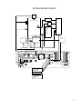
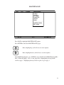
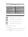
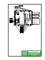
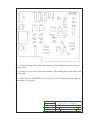
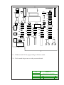
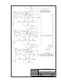
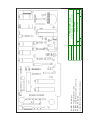
1
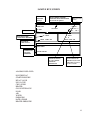
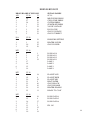
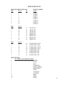
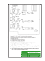
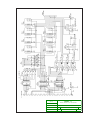
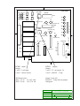
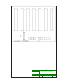
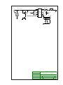
Instruction Manual
MANSC10070B
Rev. D0201
SC-20
DIGITAL SYSTEM CONTROL
Software Version _________
Serial Number:______________
Eddy Company
13590 Niabi Road
Apple Valley, CA 92308
Phone: 760-961-8457 Fax: 760-961-8458
Internet address: www.eddyco.com
TABLE OF CONTENTS
GENERAL INFORMATION:
Basic Description……...…...……………………………………….
Limited Warranty ……....................................…..…………...........
Unpacking/User Responsibility …………..………...….…………..
Initial Start-up ……...…...…………………………………………
1
2
3
4
DESCRIPTION AND SPECIFICATIONS:
Front Panel Description ……………...…………………………….
Rear Panel …...…...………………………………………………..
Rear Panel Pin Assignments ………...…...………………………..
SC-20 System Specifications …………...…………….…………...
5
7
8
10
INSTALLATION:
Operator Safety …………………………...…...…………………..
System Interconnect ………...…...…………………….…………..
Installation Instructions …………….…...…………………………
11
13
14
OPERATION:
Start Up ……………..…...…………………………….…………..
Set Clock …..…...………………………………………………….
Maintenance ………...……………………………………………..
Manual Operation …………...……………………………………..
System Parameters …………...……………………….…………...
Regen Parameters …………...……………………………………..
Alarms ….…...……………………………………………………..
Edit ..……...………………………………………………………..
End of Process …….…...…………………………………………..
Run Mode ……...…………………………………………………..
Run Screen …..…...………………………………………………..
18
19
21
22
27
29
31
35
41
42
42
TABLES AND BOARD INFORMATION:
EDDY-20 Bus List ……...…………………………………………
SC-20 I/O Assignments ………...………………………………….
Initial Board Alignment Procedure ……………...…....…………...
44
47
48
ENGINEERING DRAWINGS
System Assembly SC10ASY00400 …………………………...………
Interconnect Schematic DWGSC100072 ....……………………….….
Planetary Heater Control SCHSC10060E …………...………….…...
Planetary Heater Control ASYSC10060E ..………….....……….…...
Ion Gauge and Valve Control SCHSC10062E …………….………...
Ion Gauge and Valve Control SC10ASY0062E ..……………………
Thermocouple Gauge Control SCHSC10063C …..……………..…...
Thermocouple Gauge Control DWGSC10063C …………..….……
BUS I/O Board SCHSC10064F ..……………………………………
BUS I/O Board BUS10ASY064F ........................................................
EDDY BUS BUSASY066D .................................................................
Cryo-Regen and Control Board DWGSC100065A …………..……...
Cryo-Regen and Control Board ASYCRYO0065A …………....…....
Ion Gauge Log Amplifier SCHSC100067B ..………………………..
Ion Gauge Log Amplifier SC10ASY0067B ……...…………….……
Power Supply SCHSC100068C ....…..………………………….……
Power Supply SC10ASY0068C .....……………………………….…
Brain Board BRAINSCH069Q ..……………………………….…….
Brain Board BRAINASY069Q …...…………………………………
A
B
C
D
E
F
G
H
I
J
K
L
M
N
O
P
Q
R
S
BASIC DESCRIPTION
The SC-20 is a stand alone vacuum system controller that incorporates several functions
common to most coating processes. In addition to controlling substrate rotation, substrate
heating, ion processing and pressure control (gas bleed), it can run user selected sub-routines
to supervise, monitor and analyze performance. Error signals can be generated due to abnormal system performance and simple command inputs provide for the action to be taken when
an alarm is triggered.
A combination of RS-232 and bits in/bits out provides communication to external subsystems. An example would be the SC-20 combined with a LMC-20, XYC-20, crystal rate
and deposition controller plus an electron beam power supply and source which would
provide an automatic multilayer metallization system.
The SC-20 is available in configurations for diffusion pumped, turbo-pumped and two types
of cryo-pumped systems. A simple exchange of E-proms allows the SC-20 to be
reconfigured in your facility. Multiple RS-232 communication and I/O ports enable the SC20 to interface with other system components to make a totally automatic coating system.
The standard software will communicate with CTI and APD onboard electronics or with an
internal board with CTI and APD systems without electronics.
1
LIMITED WARRANTY
This SC-20 System Controller is warranted against defects in materials and workmanship for
a period of one year from the date of shipment to the original purchaser. This warranty will
be void if the instrument is not properly operated under conditions of normal use and if
normal and accepted maintenance protocols are not performed.
Defects resulting from, or repairs necessitated by, improper installation, misuse, negligence,
accident or corrosion of the equipment or any cause other than defective materials or workmanship are not covered by this warranty. No other warranties are expressed or implied,
including but not limited to the implied warranties of merchantability and fitness for a particular purpose. Eddy Company is not liable for consequential damages resulting from the
use of its equipment.
Purchaser’s sole and exclusive remedy under the above warranty is limited to Eddy Company, at its option, repairing or replacing any item which proves to be defective during the
warranty period provided the item is returned to Eddy Company together with a written
statement of the problem encountered. Any such obligation on the sellers part is subject to
the following requirements: 1) defect must be promptly reported to the seller, 2) if so advised
by the seller, component must be returned to the seller, no later than seven (7) days after the
end of the warranty, and 3) on examination by the seller the part or component must be found
to comply with the above warranty. Any item claimed to be defective during the warranty
period must be returned to the builder with the transportation charges prepaid. The purchaser
will pay return trip transportation charges. In the event that the seller elects to refund the
purchase price, the instrument shall be the property of the seller and shall be promptly
shipped back to the seller at the seller’s expense. Eddy Company reserves the sole right to
determine whether service is covered by the warranty.
If there are any questions about any of the equipment, parts or service call EDDY Company.
For all repairs, whether or not they are covered by the warranty, call EDDY Company service
line or contact our Internet address.
Phone number: 760-961-8457
Internet: www.eddyco.com
If the equipment needs to be returned for any reason you will be given a Return Material
Authorization (RMA) number.
2
DANGER
Potentially lethal voltages may exist in the unit, even with the power switched off.
Service should be attempted only by experienced personnel. Failure to observe safety
protocols that are standard for high voltage equipment could result in personal injury.
UNPACKING
1.
Completely unpack the instrument. Your SC-20 was released to the carrier in good
condition and properly packed. It is essential to examine the contents of the shipment
to ensure that no damage occurred during transit.
2.
Compare the shipped materials to the packing list. Items included with your SC-20
are:
a. SC-20 System Controller.
b. Operation and service manual.
c. Power cord.
d. Installation kit: 1 - 37 pin AMP male system connector, 37 pin strain relief,
2 – 14 pin AMP male connector, for I/O and tooling drive, 2 – 14 pin strain reliefs,
3 – 9 pin female D-sub connectors for TC 1,2, and 3, 3 – 9 pin strain reliefs, 65 –
male pins (24AWG), 2 – 8 amp SB fuse, and 2 - 2 amp SB fuse, 2 – 1 amp SB
fuse.
3.
Call EDDY Company first if there are any problems.
Phone: 760-961-8457
Fax: 760-961-8458
USER RESPONSIBILITY
This equipment will perform in accordance with the instructions and information contained
in the user’s manual when the equipment is installed, operated and maintained in compliance
with the instructions. Equipment should be checked periodically, routine maintenance
performed and broken or non-working parts replaced immediately.
The user/purchaser shall have sole responsibility for any malfunctions resulting from their
improper use or lack of maintenance of the equipment.
3
INITIAL STARTUP
1.
Read the manual.
2.
Connect all shipped parts.
3.
After reading the manual, establish that all the connected instruments are working
properly.
4.
Connect power, check that line cord matches the line voltage and turn the SC-20 on.
5.
The main menu will appear.
6.
Adjust the brightness and contrast for optimum viewing.
4
FRONT PANEL (description)
Brightness
Contrast
Programming switches
Increase/decrease
highlighted values
DIGITAL SYSTEM CONTROL SC-10
ENTER
HEAT
PAGE
E
D
D
Y
INC +
STAND
EXIT
BY
DEC -
INC +
VENT
SHUT
DOWN
DEC -
POWER
VACUUM
THE EDDY CO.
LCD screen
Power ON/OFF
Sequence select switches
Moves highlight
Up / Down
ENTER
PAGE
This key starts the selected program or edits selected programs.
Will change the display page.
EXIT
Returns to the initial display.
HEAT
While flashing, the controller:
1. Brings system to high vacuum.
2. Turns on ion gauge and enables the E-gun interlock.
3. When the specified pressure is met, heats the substrates for
the prescribed time.
4. Turns on planetary.
When HEAT stops flashing itsends a signal via the RS-232 line to
enable the coating process.
5
VACUUM
STAND
BY
VENT
SHUT
DOWN
Brings the system to high vacuum, starts the ion gauge and enables the
E-gun interlock.
Turns off heaters, planetary, ion gauge, and E-gun interlock, then
closes high vacuum.
Opens slow vent for programmed time, then vent valve
Closes high vacuum valve, and turns off cryo pump or diffusion pump,
then if applicable, stops the mechanical pump.
6
REAR PANEL
GUN
TC-1
IO N GA UGE
GLOW UNIT
TOO LING DRIV E
SYSTEM
DI GITAL I/ O
TERMINA L
PRINTER
TC-2
CRYO PUMP
COL.
VA LV E
VA LV E
2 AMP
LMC-10
TC-3
8 AMP
IN PUT 97-245 V AC
50-60 HZ
2 A MP 120
1 AMP 240
( SLOW FUSE)
FUSE
POWER INPUT:
Plug/fuse/volt/sw
DATA PORTS-RS 232:
TERMINAL PORT: This port allows you to communicate via
EddyLog and EddyLink software with the computer.
PRINTER: Not enabled with V 6.2
CRYO PUMP:
Communicates to either CTI (on board) computer, or APD (on board)
computer or our internal cryo control board.
LMC-10:
Not enabled with V 6.2
TC 1:
Thermocouple 1 connects to a pressure sensor at the mechanical pump.
TC 2:
Thermocouple 2 connects to a pressure sensor at the cryo pump.
TC 3:
Thermocouple 3 connects to a sensor in the chamber.
ION GAUGE:
Connects to the Ion gauge with a supplied Log Amplifier.
GUN GLOW UNIT: Provides cryo control signals
TOOLING DRIVE: Connects to the planetary motor
SYSTEM:
Provides complete system control signals
DIGITAL I/O:
Provides alarm signals and input for 02 bleed enable
COL.:
Not enabled with V 6.2
VALVE:
Not enabled with V 6.2
VALVE:
Signal lead for the 02 bleed valve
The 2-amp fuse is for the planetary motor and the 8-amp fuse is for the ion filament.
7
REAR PANEL ( pin outs)
With CRYO-REGEN BOARD (ASYCSCRYO65A)
SYSTEM
J-10
SIGNAL
RETURN
1
14
2
14
3
14
4
14
5
15
6
15
8
15
7
12
9
14
10
15
11
NOT PGMD
16
12
17
12
18
21
19
21
20
NOT PGMD
29
NC*
30
31
32
33
34
NC*
35
NC*
36
37
15
DESCRIPTION
MECHANICAL PUMP
CRYO PUMP
FORELINE
ROUGHING
HIGH VAC VALVE
VENT
SLOW VENT
SLOW ROUGH
HOT WATER
SUBSTRATE HEATER
GLOW BLOCK
PLATE VALVE
CHAMBER DOOR
AIR
WATER
SUBSTRATE-RTD
HEATER POWER +10V
OK TO COAT
VACUUM INTERLOCK
DIGITAL I/O J-11
SIGNAL
RETURN
DESCRIPTION
1
3
02 INPUT #1
2
3
02 INPUT #2
4
5
ALARM 1
6
7
ALARM 2
* NC- NOT CONNECTED
8
REAR PANEL ( pin outs)
With CRYO-REGEN BOARD (ASYCSCRYO65A)
GUN GLOW (misnamed) J-7
SIGNAL
RETURN
DESCRIPTION
2
1
CRYO PUMP PURGE
3
1
HEATER (CRYO PUMP)
4
1
CRYO ROUGH
5
NC*
6
NC*
8
NC*
7
NC*
9
NC*
10
CRYO DIODE ( - ) 100 ma
11
CRYO DIODE ( + ) 100 ma
12
RSTX ( TO RS232 CRYO PUMP P14)
13
RX (TO RS232 CRYO PUMP P14)
14
RSCOM (TO RS232 CRYO PUMP P14)
TOOLING DRIVE
1
2
3
4
5
J-9
FIELD 2
FIELD 1
ARMATURE 1
ARMATURE 2
TOOL DRIVE GROUND
BNC
J-6
CONNECTS TO THE 02 BLEED VALVE
* NC – NOT CONNECTED
9
SC-10 SYSTEM CONTROLLER SPECIFICATIONS
All inputs and outputs are optically isolated for noise immunity. The SC-10 uses a
motherboard which communicates with analog signals between the input/output boards and
the main processor board. It is possible to trouble shoot the SC-10 with a digital voltmeter.
CABINET:
DISPLAY:
WEIGHT
SHIPPING WEIGHT
AC INPUT VOLTAGE RANGE:
POWER OFF MEMORY LIFE:
PLANETARY CONTROL:
ION GAUGE:
THERMOCOUPLE VACUUM GAUGE TUBE:
TEMPERATURE SENSOR SPECS:
HEATER OUTPUT:
REAR CONNECTORS:
Digital I/O port:
System:
Tooling drive:
Gun/Glow unit:
Ion Gauge:
TC Pressure Transducer:
Piezoelectric valve:
Col:
DATA PORTS-RS-232:
Terminal:
Printer
Cryo pump
LMC-10
5.25” x 19” x 16” deep includes
mounted parts on rear panel
Fluorescent backlit LCD
22 lbs
28 lbs
97 to 245 VAC. 50/60 Hz
Power: 250 VA
Fuse: 120V - 2 amp slow fuse
Fuse: 240V - 1 amp slow fuse
60 months
3 AMP. D.C. motor:
armature......0-120 VDC
field.............110VDC
typical motor: .........Bodine 33 Series
Baldar 2318P
2 amp SB fuse on back panel.
Bayard Alpert, typically 563, with
platinum coating and iridium filament.
Dunaway Stockroom, 1-100-NC, with
platinum coating and thoria coated
iridium filament.
8 amp SB fuse on back panel
Varian 531 or equivalent
100 ohm rtd
0-10 VDC
14-pin twistlock
37-pin twistlock
14-pin twistlock
14-pin twistlock
14-pin twistlock
4 -pin twistlock (3x)
BNC (2x)
BNC
9600 baud
Not enabled with V 6.2 software
Depending on software connects to
CTI,APD or our control board
Not enabled with V 6.2 software
10
OPERATOR SAFETY
DANGER:
Potentially lethal voltages may exist within this unit, even with the power shut off. Only
qualified personnel should attempt service. Failure to observe all safety precautions may
result in personal injury.
Observe the following precautions when servicing this instrument because of the potential
high voltage.
1. Make sure HIGH VOLTAGE WARNING signs are posted in the service area.
2. Remove rings, watches, bracelets, and any other metal jewelry before working around
high voltage.
3. DO NOT WORK ALONE.
4. Be sure all equipment is connected to a power source that has the correct polarity and
grounding, as prescribed by the local electrical codes.
5. Before servicing equipment be sure it is switched off at the main power switch. This
switch should have a lock out feature.
6. Use a grounding hook to discharge any electrical parts that hold a lethal voltage after
shutoff. Be sure these parts are discharged before attempting any repairs.
7. Do not touch any high voltage leads unless the power is off and a grounding hook is
connected to the parts being serviced.
8. This instrument’s high-voltage components are equipped with electrical interlocks to
protect personnel from injury. DO NOT ATTEMPT TO DEFEAT, OVERRIDE, OR
BYPASS THESE PROTECTIVE DEVICES.
9. Never leave loose ends on high voltage devices.
11
HEALTH HAZARD
The nature, as well as the form, of the condensates deposited on the tank walls and the
materials used in the coating processes can pose health hazards. Some precautions to take
include the following:
1.
To prevent inhaling the fine particles and prevent damage to the lungs, wear a
protective respirator mask that has been approved for this use by the National
Institute for Occupational Safety.
2.
Some of these materials are toxic. Inhaling them could prove to be deadly.
Be sure to know the toxic qualities of each material being worked with.
3.
Certain materials can cause flash fires when exposed to oxygen. (Example:
Titanium). When opening the chamber door after running a process use
extreme caution.
12
SYSTEM INTERCONNECT
PL ANETAR Y
DRIVE
MOTOR
HEATER RE LAY
AND S. CR
. .
CONTROL
O2
VALVE
OPTO
ISOL A TOR
BOAR D
M.P . RE LAY
FUSE D
CHAMBER
T.C.
ALL SY STEM
STATUS
SWITCHES
DOORS
AIR
WATER
VACUUM
POWER
HEATER
2 4 VAC
CONTROL
OUTPUTS
GUN
RE S SOURCE
H.V. VALVE
ROUGH VALVE
C TI ONBOAR D
FOR ELINE
VALVE
MECH PUMP
CRYO
PUMP
RS -2 3 2
CRYO
MECH PUMP T.C.
GUN
ION GAUGE
T.C.
TOOL ING
DRIVE
GLOW UNIT
T C- 1
SY STEM
DIGITAL I/O
TERMINAL
PR INTER
T C- 2
CRYO PUMP
COL
.
VALVE
2 AMP
VALVE
LMC-10
T C- 3
8 AMP
O 2 VALVE
INPUT 9 7- 2 45 VAC
5 0- 6 0 HZ
2 AMP 1 20
1 AMP 2 40
(SL OW FUSE )
FUSE
SC-1 0
TO COMPUTER WITH
EDDY LOG AND EDDY
LINK SOFT WAR E
NOT USED WITH V 6. 2
OPT IONS:
1 . CTI ONB OARD
2 . APD O NBOARD
3 . INTERNAL CRYO
CONTRO L
13
INSTALLATION INSTRUCTIONS
REAR PANEL
DANGER
POTENTIALLY LETHAL VOLTAGES MAY EXIST WITHIN THIS UNIT, EVEN WITH THE
POWER SHUT OFF. ONLY QUALIFIED PERSONNEL SHOULD ATTEMPT SERVICE.
FAILURE TO OBSERVE ALL SAFETY PRECAUTIONS MAY RESULT IN PERSONAL
INJURY.
GUN
TC-1
IO N GA UGE
GLOW UNIT
TOO LING DRIV E
SYSTEM
DI GITAL I/ O
TERMINA L
PRINTER
TC-2
CRYO PUMP
COL.
VA LV E
VA LV E
2 AMP
LMC-10
TC-3
IN PUT 97-245 V AC
50-60 HZ
FUSE 2 A MP 120
1 AMP 240
( SLOW FUSE)
8 AMP
POWER INPUT and FUSE HOLDER:
The SC-20 can be configured to use either 120 VAC or 240 VAC. The voltage
selected is controlled by the CORCOM power card which is installed in the
slot below the fuse holder. To remove the card use a pair of needle nosed pli
ers and pull out. To configure for 120 volts turn card so the 120 is right side
up and facing you. For 240 volts turn the card over so 240 is right side up
and facing you. Insert card into slot. Make sure the fuse is the right one for
the voltage selected. 120 volts requires the 2 amp SB fuse and 240 v requires
the 1 amp SB fuse.
TO POWER
PLUG
FUSE
INPUT VOLTAGE
SELECTOR
14
SYSTEM:
Wiring for the system hookup is user supplied. A 37 pin AMP connector with a strain relief
is supplied by the EDDY Company. Using the following pin descriptions to construct a cable
for the hook up. EDDY Company suggests using 24-gauge wire no longer than 30 feet. We
recommend using 1 male and 1 female and wiring pin for pin at the electrical box.
SYSTEM J-10
SIGNAL RETURN
1
14
2
14
3
14
4
14
5
15
6
15
7
8
15
9
14
10
15
11
16
12
17
12
18
21
DESCRIPTION
MECH. PUMP
CRYO PUMP
FORELINE
ROUGHING
HIVAC VALVE
VENT
NC
SLOW VENT
HOT WATER
SUBSTRATE HEAT
NOT PGMD
PLATE VALVE
CHAMBER DOOR
AIR
SIGNAL
19
20
29
30
32
34
35
36
37
RETURN
21
31
33
15
DESCRIPTION
WATER
NOT PGMD.
NC
SUBSTRATE-RTD
HEATPOWER+10V
NC
NC
OK TO COAT
VAC INTERLOCK
TOOLING DRIVE:
Wiring for the tooling drive is user supplied, EDDY Company suggests using 22-gauge wire, no
longer than 30 feet for the cable. Using the supplied 14 pin AMP connector construct a cable
using the following descriptions:
TOOLING DRIVE J-9
1
FIELD 2
2
FIELD 1
3
ARMATURE 1
4
ARMATURE 2
5
TOOL DRIVE GROUND
GUN GLOW UNIT (Used for cryo pump control):
Wiring for the Gun Glow Unit is user supplied, EDDY Company suggests using 22-gauge
wire, no longer than 30 feet for the cable. Use the following table to construct a cable.
15
GUN GLOW
SIG. RET
1
2
1
3
1
4
1
5
NC
6
NC
7
NC
J-9
DESCRIPTION
CRYO PUMP PURGE
HEATER (CRYO PUMP)
CRYO ROUGH
SIG
8
9
10
11
12
13
14
DESCRIPTION
NC
NC
CRYO DIODE (-)100MA
CRYO DIODE (+)100MA
RSTX(TO RS232 CRYO PUMP P14)
RX(TO RS232 CRYO PUMP 14)
RSCOM(TO RS232 CRYO PUMP P14)
ION GAUGE:
The cable for the Ion Gauge is supplied by EDDY Company with a Log Amplifier connected.
DIGITAL I/O:
The wire for the I/O connection is user supplied. EDDY Company supplies a 14 pin AMP
connector and the required pins.
DIGITAL I/O
J-11
SIGNAL
RETURN
1
3
2
3
4
5
6
7
DESCRIPTION
02 INPUT #1
02 INPUT #2
ALARM 1
ALARM 2
To connect the instrument’s I/O ports to another device make a list of the outputs and related
inputs for the device being used.
Organize into sets of I/O connections and assign wire colors for each connection. Cut each
wire to the desired length and crimp the supplied pins to them. Do not solder the wires to the
pins.
Gather the wires that will be connected to the I/O port and insert into the tapered strain relief
portion of the plastic AMP connector. Using the list of I/O connections and the AMP connector portion that plugs into the back of the instrument insert the individual wires into the holes
with the corresponding numbers.
After securing the wires in the AMP connector with the tabs for that purpose, plug the assembled connector into the appropriate I/O port in the back panel. Make similar connections
for the other end of the wires for the other device’s port. Wire and test for correct connections with an ohm meter against original design.
16
TC 1,2,3
Thermocouple 1 connects to a pressure sensor at the mechanical pump
Thermocouple 2 connects to a pressure sensor at the cryo pump.
Thermocouple 3 connects to a pressure sensor in the chamber.
SC-CRYOTC-BLA
SC-CRYOTC-RED
SC-CRYOTC-WHI
SC-CRYOTC-GRN
SC-CRYOTC-BLA
The wire for the cables is user supplied. A 4 conductor, 22 gauge wire is suggested. Using
the supplied 9 pin female-D sub connectors and the following diagram construct cables to
connect to the associated devices.
R1
TC1
4
3
5
SC-CRYOTC-RED
SC-CRYOTC-WHI
1
SC-CRYOTC-GRN
1
7
COL.:
Not enabled with V 6.2
VALVE:
Not enabled with V 6.2
VALVE:
This has a BNC connection using a coaxial cable to the 02 bleed valve.
FUSES:
The 2 amp fuse is for the planetary motor and the 8 amp fuse is for the Ion filament. There
are fuses included in the installation kit
17
SYSTEM STARTUP
The power switch lights and startup screen is displayed. RUN is highlighted.
Note: Allow screen to fully draw. It displays at 8 mHz.
RUN
SC-20
EPROM HEADER
EDIT
ALARMS
MAINTENANCE
V7.x
EDDY CO.
SOFTWARE VER. AND PRODUCTION VER.
Press PAGE to highlight MAINTENANCE.
Press ENTER to show MAINTENANCE page options. Use UP ARROW or DOWN
ARROW key to highlight SET CLOCK. Press ENTER to show SET CLOCK screen.
18
SET CLOCK
- SET CLOCK 18 =
- AUTO START -
SECONDS
18 =
SECONDS
37 = MINUTES
37 = MINUTES
17 =
HOURS
17 =
HOURS
05 =
DATE
05 =
DATE
05 =
MONTH
05 =
MONTH
9 2 = YEAR
9 2 = YEAR
OFF
SC-20
V7.x
EDDY CO.
Moves highlight up (will roll over) to select values.
Moves highlight down (will roll over) to select values.
PAGE
Toggles you from one column to the other.
Values that are highlighted can be changed.
INC +
Will increase selected value.
DEC -
Will decrease selected value.
19
AUTO START:
To set up AUTO START do the following.
1. Push the PAGE key to move you from the CLOCK column to the AUTO
START column.
2. Set the Date and Time in which you want the system to start.
3. Now highlight OFF and push the + key.
4. Push EXIT and now select a PROGRAM and run it.
5. There are three ways in which the AUTO START can run. You can leave
the system in STANDBY and the system will AUTO START at the
specified time and date. It will also check to see if the main chamber needs
roughing. Or once you run your PROGRAM you can push VACUUM and
put the system into high vacuum and the system will AUTO START at the
specified time and date. The third way is it can start the system from the
begining meaning it will start the cryo pump, wait till it is at temerature,
and go into HEAT at the specified time and date. The section below
describes the steps the system take to
EXIT:
Returns the system to the main menu.
Use arrow keys and INCR+ and DECR – to select the current date. Press EXIT to return to
the main menu.
HOW IT WORKS:
Sets up time for system to start up automatically.
1. System will check to see if cryo chamber pressure is below 100 mtorr, then
will proceed to next step. (If chamber is not at this pressure it will start
mechanical pump).
2. System will check temperature, It must be 20K or below to
proceed. If not, it will wait until cryo pump lowers the temperature.
3. If main chamber pressure is below crossover (example: 80 mtorr) and the
temperature is met, it will open the hivac valve. (If chamber is not below
80 mtorr then it will start mechanical pump.)
4. After it reaches the right pressure the system will go ito high vacuum and
proceeds to turn on heater, planetary starts and the system is ready to run.
20
MAINTENANCE
RUN
EDIT
ALARMS
MAINTENANCE
PUMPS
VALVES
ION GAUGE
PLANETARY
HEATER
GLOW
------------SYSTEM PARAM.
SET CLOCK
SC-10
V7.x
THE EDDY CO.
Press PAGE to highlight MAINTENANCE option.
Press ENTER to enter the MAINTENANCE pages.
Moves highlight up (will roll over) to select options.
Moves highlight down (will roll over) to select options.
With PUMPS highlighted, press ENTER to show MANUAL OPERATION / PAGE 1.
Note: When the pumps, valves, or ion gauge line is highlighted pressing PAGE
scrolls to page 2. Highlight planetary, heater or glow to go to page 3.
21
MANUAL OPERATION
This page displays thermocouple gauge pressures, ion gauge pressure when the gauge is
turned on and high vacuum valve status.
-
MANUAL
OPERATION
/
PAGE 1 -
OUTPUTS
-
MECH
INPUTS
PUMP
MECH
PRS
=
100
- CRYO PUMP
CRYO
PRS
=
100
-
SYST
PRS
=
100
ROUGHING VALVE
- SLOW ROUGH VALVE
ION
-
FORELINE
HIGH
-
HIGH
VAC VALVE
-
MAIN
VENT
-
SLOW
VALVE
VENT
GAUGE
VAC
=
5.5
-6
OPEN
VALVE
VALVE
- HEAT/EGUN INTLK
SC-20
V7.x
EDDY CO.
Moves highlight up (will roll over) to select options.
Moves highlight down (will roll over) to select options.
INC +
Will turn on device or open selected valve.
DEC -
Will turn off device or close selected valve.
The + and – indicate whether highlighted item is enabled or disabled.
CAUTION: THESE OPERATIONS ARE NOT PROTECTED. INAPPROPRIATE TESTING/DIAGNOSTIC ACTIONS MAY RESULT IN SYSTEM FAILURE. The standby light
on the front panel is on during MAINTENANCE page display.
22
- MANUAL
OPERATION
/
PAGE 2 -
OUTPUTS
INPUTS
-EMISSION LOW
FILAMENT
-EMISSION HIGH
ION
IS
GAUGE
OFF
=
5 .5
- 6
-DEGAS
PRESS.
=
1 .0
-5
TIME CONSTANT
=
SC-20
0
VALVE
VOLTS =
O2
# 1
OFF
O2
#2
OFF
V7.x
100
EDDY CO.
Moves highlight up (will roll over) to select options.
Moves highlight down (will roll over) to select options.
INC +
Will turn on device or increase selected value.
DEC -
Will turn off device or decrease selected value.
EMISSION LOW:
This is used for normal coating operations. The emission is factory set
for 1 MA.
EMISSION HIGH:
Not enabled with V 6.2.
DEGAS:
This is an I2 R heater control.
PRESS.:
INCR + / DECR - will select the target pressure for 02 bleed valve.
23
TIME CONST.:
INCR + and DECR – will change the time constant for the 02 bleed
valve.
This page displays the filament status, ion gauge pressure reading, voltage to servo valve and
the status of the external 02 bleed signals.
Testing the ion gauge servo valve control system:
1. First set time constant to 3 or 4.
2. Select emission low and press INCR+.
3. Ion gauge should read system pressure, valve volts should increase and system
pressure should match required pressure.
4. Set pressure to 5.0 – 5.
5. Observe real pressure is near 5.0 10-5.
24
Press PAGE to display page 3
-
MANUAL
OPERATION
/
PAGE 3
OUTPUTS
-
INPUTS
-PLANETARY
LOW
DOOR
OPEN
-PLANETARY
HIGH
AIR ON
-PLANETARY
REVERSE
WATER
ON
-HOT WATER
HEATER
PWR
-GLOW
BLOCK
GLOW
POWER
TIME
CONST
SC-20
=
0
=
=
SUBSTRATE
0
0
V7.x
=
3 00
2.0
K.V.
GLOW
=
GLOW
2 50
GLOW
INTLCK
C
MA
ON
EDDY CO.
Moves highlight up (will roll over) to select options.
Moves highlight down (will roll over) to select options.
INC +
Will turn on selected device or open selected valve.
DEC -
Will turn off selected device or close selected valve.
The + and – indicate enabled or disabled.
PLANETARY LOW:
Will slow start planetary to operate at low speed for heating substrates.
PLANETARY HIGH:
Will slow start planetary to operate at high speed for coating.
25
CAUTION
CAUTION
CAUTION
PLANETARY REVERSE:
Will hard reverse the planetary with no ramp up or down (this must
only be used when planetary is completely stopped).
HOT WATER:
Controls the system heater used to control condensation during venting on
some vacuum systems.
HEATER POWER:
Increasing this value above zero will enable the heater units and selecting a
value between 1 and 100 will give an output ranging from .1 volts DC to 10.0
volts DC.
GLOW BLOCK:
Not enabled with V 6.2.
GLOW POWER:
Not enabled with V 6.2.
TIME CONST.:
Not enabled with V 6.2.
This page displays the door, air and water status, the temperature of the substrate and the
glow discharge status.
EXIT
Will return system to the original screen with maintenance
highlighted.
Press ENTER to select maintenance options. Use down arrow to select SYSTEM PARAM.,
then press ENTER.
26
SYSTEM PARAMETERS
SYSTEM PARAMETERS -
ION GAUGE HIGH FILAMENT PRESS. =
ION GAUGE
RESTART
LIMIT =
PAGE 1
0.0
-7
4
PRESS. CONTROL TIME CONSTANT = 0
HOT WATER ON
TIME = 0 MINUTES
GLOW CONTROL TIME CONSTANT = 0
TEMPERATURE CONTROL TIME CONSTANT = 0
TEMPERATURE CONTROL ERROR RANGE = 0 C
TEMPERATURE CONTROL ERROR TIME = 0 SEC
CRYO
PUMP
SC-20
COMMUNICATIONS
OFF
V7.x
EDDY CO.
Moves highlight up (will roll over) to select options.
Moves highlight down (will roll over) to select options.
INC +
Will increase the highlighted options.
DEC -
Will decrease the highlighted options.
ION GAUGE HIGH FILAMENT PRESS.:
The system will change filament emission if the pressure is lower than
this set point. This pressure is normally left at 0.0 – 7
(not enabled in V6.2).
ION GAUGE RESTART LIMIT:
Selects the number of times the program will try to restart the
ion gauge before alarm is initiated. Suggested setting is 4.
27
PRESS. CONTROL TIME CONSTANT:
Sets the adjustment rate for the O2 bleed valve. Recommended setting “ - 3”.
HOT WATER ON TIME:
Set in minutes the amount of time the system hot water heaters will be on
before the system is vented.
GLOW CONTROL TIME CONSTANT:
Sets the rate for the bleed valve adjustment. This rate must match the
pumping speed of the system while in glow mode. Not enabled with V6.2.
TEMPERATURE CONTROL TIME CONSTANT:
Sets the rate to which the substrate heaters are adjusted to come up to required
temperature. Press INCR + or DECR - for adjustment.
TEMPERATURE CONTROL ERROR RANGE:
Sets the temperature limits that have to be exceeded before the alarm signal
sounds. The time will reset at less than error limits.
TEMPERATURE CONTROL ERROR TIME:
Sets the time required for the system to be out of the temperature range before
the alarm signal sounds.
CRYO PUMP COMMUNICATIONS OFF/ON:
Selects whether communication to the cryo pump is enabled.
EXIT
Will return system to the original screen with MAINTENANCE
highlighted.
Press PAGE to go to page 2 “Regen Parameters”
28
REGEN PARAMETERS
REGEN PARAMETERS - PAGE 2
PURGE TIME
= 0
CRYO ROUGH PRESSURE = 0
ROR MAX PRESSURE = 0
ROR TIME = 0
ROR RETRIES = 0
REGEN =
SC-20
OFF
V7.x
EDDY CO.
Moves highlight up (will rollover) to select options.
Moves highlight down (will roll over) to select options.
INC +
Will increase the number in the highlighted line.
DEC -
Will decrease the number in the highlighted line.
This operation warms the cryo pump and expels the accumulated material (water
vapor and gasses) to prepare for a new cycle.
PURGE TIME:
Time set, in minutes, to backfill and heat the cryo pump (at least one
hour).
CRYO ROUGH PRESSURE:
After roughing chamber, the pressure required to close roughing valve
and test for ROR in mtorr. (Example: 50 mtorr)
29
ROR MAX PRESSURE:
Pressure level selected for Rate of Rise test in mtorr.
ROR TIME:
The amount of time, in minutes, given to achieve selected pressure. If the test
is failed the system will pump down again for a retry.
ROR RETRIES:
Maximum retries before alarm sounds.
REGEN:
This needs to be off to use RUN command.
EXIT
EXIT to return to main menu.
HOW IT WORKS:
Set up the Auto Regeneration for the Cryo Pump.
1. Set your parameters. For example, set PURGE TIME to 60 min.,
CRYO ROUGH PRESSURE to 20 mtorr, ROR MAX PRESSURE
to 100 mtorr, ROR TIME to 2 min., and ROR RETRIES to 2.
2. Now highlight the REGEN line and press the INC + button to turn
it ON.
3. Exit to the main menu. Press PAGE till RUN is highlighted. Press
ENTER, highlight a program and press ENTER.
4. Once in a program press VACUUM or HEAT. This will start the
regen cycle. (Note: You may also use the AUTO START feature to
regen at a given time. Just remember that when you go into your
program to leave the system in STANDBY.)
5. The first thing to happen will be the shutting down of the cryo
pump. Then the system will vent the main chamber. The vent
valve is on a 15 min. timer.
6. After 15 min. the cryo purge valve will open and the cryo heating
blanket will turn on. The cryo will purge for the time you speci
fied.
7. When the purge is complete the system will then rough out the cryo
chamber.
8. The system will now start the ROR test. If it fails the test, meaning
that the pressure exceeds the max set pressure, it will then pump out
the cryo chamber again before running another ROR test. If it
passes, the system will start the cryo pump and proceed to go
through the sequences to get to which ever state you specified
(VACUUM or HEAT)
30
ALARMS
Press PAGE to highlight ALARM option
RUN
EDIT
ALARMS
MAINTENANCE
ROUGH/HIVAC
START PRESS
HIVAC VALVE
ION GAUGE
CRYO PUMP
HEATER
GLOW INTRLK
DOOR
AIR
WATER
PRESSURE
RATE OF RISE
HEATER PRESS
SC-20
V7.x
EDDY CO.
All the devices that make up the system are connected to alarms that initiate if the parameters
programmed are not met. They can be programmed for the number of beeps per second, the
action to be taken by the SC-10 and how the operator is made aware of the alarm; by phone,
audible alarm or a light.
Moves highlight up (will roll over) to select options.
Moves highlights down (will roll over) to select options.
ROUGH/HIVAC:
Alarms if roughing time is exceeded to bring the pressure down to crossover to Hivac.
START PRESSURE:
Alarms if pressure isn’t reached in the time set to begin the coating process.
31
HIVAC VALVE:
Position alarm, if hivac valve does not achieve position when signaled
within 30 seconds time. (opening or closing)
ION GAUGE:
Will alarm if ion gauge has failed. If there is a failure in the system, it
puts system on standby (recommended setting).
Note: The ion gauge alarm must be set before the system is run in
automatic. Suggested setting is 3 tries before alarm initiates.
CRYO PUMP:
Alarms if temperature exceeds software set temperature of 20 degrees
Kelvin.
HEATER:
Alarm sounds if temperature is out of range for time set. An example
would be if the temperature was 20 degrees over the set temperature
past a two minute time period.
GLOW INTERLOCK:
Alarms if interlocks aren’t enabled. Not used with V 6.2.
DOOR:
Alarms if vacuum chamber door is not closed.
AIR:
Alarms if the air pressure falls below the set point of the low
pressure sensor at the switch (typically 30 psi).
WATER:
Alarms if water pressure falls below the set point of the low pressure
sensor at the switch (typically 30 psi).
PRESSURE:
When you set the #1 and #2 oxygen pressures this alarm will initiate if
the set pressure range (high and low-pressure amounts) is exceeded for
the set control time. An example would be 2.0 for 20 seconds. Set
these parameters within the needs of your process.
(See program 1, page 3).
RATE OF RISE:
Alarms if pressure exceeds the limit pressure inside the time paraeters
on the final retry on the Rate of Rise test.
HEATER PRESSURE:
Alarms if over set pressure limit during heat cycle.
32
THIS SCREEN IS TYPICAL FOR ALL LISTED ALARMS.
With ROUGH/HIVAC highlighted press ENTER
ALARM : ROUGH/HIVAC
SEC/BEEP :
OFF
ACTION
NONE
:
OUTPUT :
SC-20
NONE
V7.x
EDDY CO.
Moves highlight up (will roll over) to select options.
Moves highlight down (will roll over) to select options.
With SEC/BEEP highlighted:
INC +
Will increase the interval (in seconds) for beeps in the
highlighted line.
DEC -
Will decrease the interval (in seconds) for beeps in the
highlighted line down to 1, then to off.
With ACTION highlighted
OPTIONS: NONE-SHUTDOWN-VENT-STANDBY-VACUUM.
INC +
Will increase the option with VACUUM as the limit.
33
DEC -
OUTPUT:
Will decrease the option with NONE as the limit.
Alarm may be enabled to phone safety number, initiate an audible
alarmor turn on a light.
OPTIONS:
None
Output alarm 1
Output alarm 2
Both alarms.
The alarm outputs are common. An example would be (in order of
Importance) to set alarm 1-system failure, alarm 2-process stop and
less important would be alarm-none.
INC +
Will increase the selection with BOTH as the limit.
DEC -
Will decrease the selection with NONE as the limit.
PAGE
Will cycle through the list of alarms.
EXIT
Returns program to main menu.
34
EDIT
RUN
EDIT
PROGRAM
PROGRAM
PROGRAM
PROGRAM
SC-2 0
ALARMS
MAINTENANCE
1
2
3
4
V7.x
EDDY CO.
Press PAGE to highlight EDIT. There are four programs that can be stored
in the SC-20.
Moves highlight up (will roll over) to select program.
Moves highlight down (will roll over) to select program.
ENTER
Press to edit the highlighted program.
35
- PROGRAM
ROUGH / HIGH
VAC
ROUGHING
LIMIT
PLANETARY
TIME
ON
(1)
1
/
CROSSOVER
=
20
PAGE 1
=
70 M TORR
MINUTES
OR OFF (0) =
PROCESS START PRESSURE =
-
2.0
1
-5
PROCESS START TIME LIMIT = 20 MINUTES
SUBSTRATE TEMPERATURE = 240
TEMPERATURE RAMP UP =
5
C
MINUTES
TEMPERATURE SOAK TIME = 30
MAXIMUM HEATER PRESSURE =
SC-20
MINUTES
0.0 -7
V 7.x
EDDY CO.
Moves highlight up (will roll over) to select line.
Moves highlight down (will roll over) to select line.
INC +
Will increase the number in the highlighted line.
DEC -
Will decrease the number in the highlighted line.
PAGE
Press to change to the next program page (total of three).
ROUGH/HIGH VAC CROSSOVER:
Selects the pressure the system is roughed to before changing from the
mechanical pump to the cryo pump. Recommended setting 50 mtorr to
90 mtorr.
ROUGHING TIME LIMIT:
Normally set for 15 minutes more than average roughing time. When
this time is exceeded the roughing alarm is activated.
NOTE: 10% of this time is for the Soft Rough feature (optional).
Here, if set to 15 minutes, a delay of 90 sec will occur before main
rough valve opens.
36
PLANETARY ON (1) OR OFF (0) = 1:
Selecting 0 leaves planetary stationary during coating. Selecting 1
turns planetary at low speed during heating cycle and automatically
increases to high speed during coating process.
HEAT START PRESSURE:
Sets the pressure required to start the heat cycle. Alarm is activated if
pressure isn’t met.
PROCESS START PRESSURE:
Sets the pressure required at end of heat soak before allowing an
external signal to be made. HEAT light blinks until pressure limit is
met.
PROCESS START TIME LIMIT:
Sets the maximum time allowed before the process alarm is activated.
SUBSTRATE TEMPERATURE:
Sets target temperature for the substrate heater.
TEMPERATURE RAMP UP:
Sets the target time to reach the substrate temperature setting.
TEMPERATURE SOAK TIME:
The time required for the substrate to be held at the required
temperature before starting the coating process.
MAXIMUM HEATER PRESSURE:
The pressure above which the heater is turned off and the heater
pressure alarm is initiated.
PAGE
Press to display page 2.
37
-
PROGRAM
1
/
PAGE 2 -
- RATE OF RISE TEST PARAMETERS TIME LIMIT = 1.0 MINUTES
START PRESSURE = 5.0 -6
LIMIT PRESSURE = 5.0 -4
RETRIES = 2
SC-20
V7.x
EDDY CO.
Moves highlight up (will roll over) to selected line.
Moves highlight down (will roll over) to selected line.
INC +
Will increase the number in the highlighted line.
DEC -
Will decrease the number in the highlighted line.
Once the appropriate parameters are entered the “rate of rise” test is used by the SC
10 to establish the general vacuum integrity of the system before the automatic
coating process begins. If you want to bypass the test set retries to 0. If the test fails
the alarm will control the action to be taken. Note: See alarm section.
To manually check the system select a pressure to start the test (50 mtorrs is
suggested). Once pressure is reached, close the valve, observe the pressure and wait.
If the pressure stays within the set limits, vacuum integrity is correct.
TIME LIMIT: The maximum time before a retry or an alarm is initiated.
START PRESSURE:
The pressure required before the “rate of rise” test starts.
LIMIT PRESSURE:
If the pressure is exceeded a retry is initiated.
Press PAGE to display page 3.
38
-
PROGRAM
GLOW
POWER =
0
GLOW
TIME = 0 MINUTES
02
PRESSURE
=
0.0
-8
#2
02
PRESSURE
=
0.0
-8
RANGE
=
PRESSURE CONTROL
TEMPERATURE
END
OF
SC-20
PAGE 3 -
0.0 -X
TIME 3 SECONDS
RAMP DOWN
PROCESS
/
MA
#1
PRESSURE CONTROL
1
= 0 MINUTES
TEMPERATURE =
V7.x
0
C
EDDY CO.
Moves highlight up (will roll over) to select line.
Moves highlight down (will roll over) to select line.
INC +
Will increase the number in the highlighted line.
DEC -
Will decrease the number in the highlighted line.
GLOW POWER:
Sets the required current for glow. Not enabled in V 6.2.
GLOW TIME:
Sets the time in minutes. The glow discharge will take place before
coating. Not enabled in V 6.2.
#1 02 PRESSURE:
Sets oxygen target pressure for process. User definable.
#2 02 PRESSURE:
Sets oxygen target pressure for process. User definable.
39
PRESSURE CONTROL RANGE:
Sets the limit of pressure deviation from required pressure before the
alarm is set. Note: do several trial runs to determine stability of run
and run parameters. Outgassing, O2 valve malfunction, air pockets
and water vapor can all influence this setting.
PRESSURE CONTROL TIME:
Is the time required for the pressure to be continuously out of the
control range before the alarm is initiated.
TEMPERATURE RAMP DOWN:
Sets the rate for the substrate temperature to be decreased before the
end of process.
END OF PROCESS TEMPERATURE:
The substrate temperature must be lower than the set temperature to
initiate the end of process.
PAGE
Press to display page 4.
40
END OF PROCESS
PROGRAM 1 /
-
HOLD AT HEAT
-
HOLD AT HIGH VACUUM
-
HOLD AT STANDBY
-
HOLD AT VENT
PAGE 4
SLOW VENT TIME = 0 MINUTES
-
SHUT DOWN SYSTEM
SC-20
V7.x
EDDY CO.
Moves highlight up (will roll over) to selected line.
Moves highlight down (will roll over) to selected line.
INC +
Will increase the number in the highlighted line.
DEC -
Will decrease the number in the highlighted line.
The + and – indicate enabled or disabled.
Highlighting the line and pressing INCR+ will select the system status required at end
of process.
SLOW VENT TIME:
Determines the amount of time slow vent will be on before fast vent is
initiated.
EXIT
Returns to startup display.
Press PAGE which will select the RUN column.
41
RUN MODE
RUN
EDIT
ALARMS
MAINTENANCE
PROGRAM1
PROGRAM2
PROGRAM3
PROGRAM4
SC-20
V7.x
EDDY CO.
Moves highlight up (will roll over) to select program.
Moves highlight down (will roll over) to select program.
ENTER
Press ENTER to start highlighted program.
The following buttons are activated in the run mode:
HEAT (FULL PROCESS):
Brings the system to high vacuum, turns on the planetary and ion
gauges, enables the E-Gun interlock, heats the substrates for the
prescribed time and brings the OK to coat signal up.
VACUUM:
Brings the system to high vacuum, starts the ion gauge and enables
the E-Gun interlock.
STANDBY:
Turns off heaters, planetary, ion gauge and closes high vacuum.
VENT:
Vents system to air.
SHUT DOWN:
Closes high vacuum valve, opens vent valve and turns off cryo pump.
42
SAMPLE RUN SCREEN
PLANETARY
ROTATION
STATUS
MAINCHAMBERPRESSURE
SWITCHES TO ION GAUGE WHEN
PLATE VALVE IS OPEN
PLANETARY OFF
MAIN VENT
- HEATER TEMP: 022 C
PWR :
00 %
999 TORR
S. VENT
ROUGHING VALVE
50 TORR
MECHANICALPUMP
PRESSURE0-1000MTORR
0 TORR
11 K
CRYO PUMP ON
MECH. PUMP OFF
MECHANICAL
PUMP STATUS
PROGRAM 1
STATEOF PROGRAM
SHUT DOWN
ALARMOUTPUT
DISPLAYED
IN SEQUENCE
HIGH VACUUM
VALVE
- STATUS-
09:10
ALARM: WATER
SC-20
V7.x
SUBSTRATE HEATER
OFF / ON / POWER
SUBSTRATE
TEMPERATURE
EDDY CO.
READS PRESSURE
TEMPERATURE AND
OPERATING STATUS
OF CRYO PUMP
ALARMS DISPLAYED:
ROUGH/HIVAC
START PRESSURE
HIVAC VALVE
ION GAUGE
CRYO PUMP
HEATER
GLOW INTERLOCK
DOOR
AIR
WATER
PRESSURE
RATE OF RISE
HEATER PRESSURE
43
EDDY-20 BUS LIST
BRAIN BOARD IC SIGNALS
A/D
IC-26
J-1
0
26
50
1
27
20
2
28
51
3
1
21
4
2
52
5
3
22
6
4
53
7
5
23
SIGNAL NAMES
SC-20
MECH PUMP PRESS
CRYO PUMP PRESS
SYSTEM PRESS
SUBSTRATE PRESS
VALVE VOLTAGE
ION GAUGE
GLOW VOLTAGE
GLOW CURRENT
D/A
0
1
2
3
IC-28
2
1
20
19
24
55
25
56
PRESSURE SETTING
HEATER POWER
GLOW POWER
BIT
0
1
2
3
4
5
6
7
IC-18
4
3
2
1
37
36
35
34
3
33
2
32
I/O BD AD 0
I/O BD AD 1
I/O BD AD 2
I/O BD AD 3
LAMP 1
LAMP 2
LAMP 3
LAMP 4
BIT
0
1
2
3
4
5
6
7
IC-18
18
19
20
21
22
23
24
25
38
8
39
9
40
10
41
11
PLANET LOW
PLANET HIGH
PLANET REV
HEAT WATER
GLOW BLOCK
GLOW ENABLE
HEATER ENABLE
READY TO COAT
BIT
0
1
2
3
4
5
6
7
IC-18
14
15
16
17
13
12
11
10
36
6
37
7
5
35
4
34
I/O BD DATA 4
I/O BD DATA 5
I/O BD DATA 6
FIL. ON
44
EDDY-20 BUS LIST
BRAIN BOARD IC SIGNALS
BIT
IC-17
J-1
0
4
1
3
2
2
3
1
4
37
5
36
6
35
7
34
SIGNAL NAMES
SC-20
LAMP 5
LAMP 6
LAMP 7
LAMP 8
LAMP 9
LAMP 10
LAMP 11
LAMP 12
BIT
0
1
2
3
4
5
6
7
IC-17
18
19
20
21
22
23
24
25
15
45
14
44
13
43
12
42
GLOW TC0
GLOW TC2
GLOW TC4
GLOW TC8
PRESS TC0
PRESS TC2
PRESS TC4
PRESS TC8
BIT
0
1
2
3
4
5
6
7
IC-17
14
15
16
17
13
12
11
10
19
49
18
48
17
47
16
46
I/O BD DATA 0 OUT
I/O BD DATA 1OUT
I/O BD DATA 2 OUT
i/O BD DATA 3 OUT
I/O BD DATA 0 IN
I/O BD DATA 1 IN
I/O BD DATA 2 IN
I/O BD DATA 3 IN
FRONT PANEL
IC-33 BRAIN BOARD DECODER
0
ENTER
1
PAGE
2
EXIT
3
UP ARROW
4
DOWN ARROW
5
SHUT DOWN
6
VENT
7
STAND BY
8
VACUUM
9
HEAT
10
DECR 11
INCR +
45
EDDY-10 BUS LIST
POWER DISTRIBUTION EDDY-10 BUS
BUS
J-1
31
1
61
30
60
29
59
28
57
SC-20
GROUND
GROUND
5
5
15
-15
24
120
I/O ENABLE
46
SC-10 I/O ASSIGNMENTS
I/O BOARD ADDRESS (PROGRAMS 1, 5)
SIGNAL
BIT
OUTPUTS
MECHANICAL PUMP
CRYO VALVE
FORELINE VALVE
ROUGHING VALVE
HOT WATER
GLOW BLOCK
ALARM 1
0
1
2
3
4
5
6
INPUTS
#1 02
#2 02
HI VAC VALVE SW
DOOR SWITCH
0
1
2
3
I/O BOARD ADDRESS (PROGRAMS 2, 6)
SIGNAL
BIT
OUTPUTS
HEATER ENABLE
READY TO COAT
VENT VALVE
HIGH VACUUM VALVE
SLOW VENT VALVE
HEAT/EGUN/PRESS INTL
ALARM 2
0
1
2
3
4
5
6
INPUTS
AIR SWITCH
WATER SWITCH
GLOW INTERLOCK
SPARE
0
1
2
3
47
SC10ASY0063C
INITIAL BOARD ALIGNMENT PROCEDURE
1. Connect TC 1, TC 2 and TC 3 to the back of the instrument.
2. With diffusion pump or cryo pump, mechanical pump and chamber at atmospheric
pressure:
1.
Set R3 to give 0.0 VDC at IC1 pin 6.
2.
Set R15 to give 0.0 VDC at IC2 pin 6.
3.
Set R18 to give 0.0 VDC at IC 3 pin 6.
4.
Start the vacuum system, pump chamber down to high vacuum and observe
ion gauge( < 1.0 10-4 torr).
5.
Adjust R9 to make cryo pump reading 000 torr.
6.
Adjust R18 for the chamber pressure to read 000 torr.
7.
Turn off diffusion pump or cryo pump, wait 20 minutes, open roughing ,
foreline and plate valves.
8.
Wait 5 minutes and then adjust R7 to make the mechanical pump reading the
48
SC10 ASY00 4 00
SKT 2060 43-1
CNT1 0 9M ND
BUS10A SY066C
SKT J-6A
BOARD 60E
R5 SET PLANETA RY LOW SPEED
R6 SET PLANETA RY HIGH SPE ED
R11 SET FOR CORRECT TEMP. READING
R5
R6
R1 8
R3
R15
R11
R18
R7
BOARD 62E
R1 8 SET TO GIV E O2 PRES SURE SAME
AS SET PRESSURE
R30 CALIBRA TE ION GA UGE READI NG
R9
R30
R1 2
M OT750 118
BOARD 6 3C
R3 MECH PUMP
SET FORA TMOSPHERIC END OF SCALE
R7 MECH PUMP
SET FOR LOW END OF S CALE
R15 CRYO PUMP
SET FORATMOSPHERIC END OF SCA LE
R9 CRYO PUMP
SET FOR LOW END OF S CALE
R18 CHAMBER
SET FORA TMOSPHERIC END OF SCA LE
R1 2 CHAM BER
SET FOR LOW END OF SCALE
SC1 0PLT0010
SC1 0ASY 0 068C
TRNLSC100 010
DDR13 30
LCDEG75 0 1DLS
BRA INASY069 E
A SYBUSI/ O64F
A SYBUSI/ O 64EF
SC10 ASY 0 06 3C
SC1 0ASY0 062D
SC1 0ASY 0 06 0E
SC1 0ASY0 061A
SWI13 112 10 25
SWI13 12610 25
EDDY
SC-20
C O
APPLE VALLEY CA. 760-961-8457
SYSTEM ASSEMBLY
A
WER
SC-10ASY10060E
A
- A -
+5V
R2
1K 1/4W 5%
B
C Q1
EMPSA20
R1
2
3
1
1
+5V
R4
1K 1/4W 5%
ROT LOW
1
ROT HIGH
2
R9
B
C Q2
MPSA20
E
R3
4.7K 1/4W 5%
IC2
VTL-5C2
PCBP2
5 PIN CONN
1
R6
10
3
2
220 1/4W 5%
IC4.A
74LS08
38
8
PCBP1
8 PIN CONN
1
S-3
S-2
S-1
A-2
A-1
F-1
F-2
4
J1
EDGE CARD
40
R5
10K
3
2
220 1/4W 5%
39
1
IC1
VTL-5C2
2
1
4
3
+15V
PLA REV
4
K1
2P DT
IC4.B
74LS08
6
5
5
6
7
8
9
10
1
D1
1N4002
4
45
9
IC4.C
74LS08
R7
10K 1/4W 5%
8
Q3
10
R8
10K 1/4W 5%
21
SUB TEMP
12
MPSA14
E
R13
40.2K 1/4W 1%
R14
10K 1/4W 1%
+15V
R15
10K 1/4W 1%
IC3 7 4 1
8
NULL1
7 V+
2
IN- 3
6
5 OUT IN+ 4
NULL V -
R10
2.73K 1/4W 1%
-15V
D2
-15V
+15V
C2
.1UF 35V TA
PCBP3
4 PIN CONN
1
R12
10K 1/4W 1%
8.2V ZENER
31
-15V
IC4.D
74LS08
11
13
WITH 110 OHMS R
SET R11 TO GIV
.550 V AT TP1
SUBSTRATE TEMP 2
C
B
C1
1UF 50V
C3
.1UF 35V
+5V
R16 10K 1/4W 1%
EDDY
SC-20
C O
APPLE VALLEY CA. 760-961-8457
PLANETARY HEATER CONTROL
A
WER
SCHSC10060E
A
- C -
R 5 - Factory set to give 20V to the motor armature. This controls power to the motor in
heating mode.
R 6 - Factory set to give 60V to the motor armature. This controls power to the motor in the
coating mode.
R 11 – With 110 ohms for the RTD it is set to give 0.5V at TB 1 and will indicate a substrate
temperature of 23 degrees C.
EDDY
SC-20
C O
APPLE VALLEY CA. 760-961-8457
PLANETARY HEATER CONTROL
A
WER
ASYSC10060C
A
- D -
SC-20
APPLE VALLEY CA. 760-961-8457
EDDY
A
WER
C O
ION GAUGE AND VALVE CONTROL
SCHSC10062E
- E -
A
+5V
6
5
IC7.B 74HCT02
3
2
IC7.A
74HCT02
R13
12
11
51KD81/4W 5%
IC7.D
1N4148
R16
9
8
13
10
4
1
74HCT02
.01UF 50V 5% IC7.C74HCT02
C18
180VDC
EDGE CARD
10K 1/4W 5%
31
62
1
32
J1
R23
1K 1/4W 5%
-15V
-15V
+5V
IN 1
D1
S1
VGND
S4
D4
IN 4
C10
.1UF 35V TA
1
2
3
4
5
6
7
8
IN 2
D2
S2
V+
NC
S3
D3
IN 3
IC6
DG202
16
15
14
13
12
+15V
11
10
9
C9 .1UF 35V TA
-15V
10K 1/4W 1%
R12
741
8
7
6
5
C14
NULL
IN- V+
IN+ OUT
V - NULL
IC4
IN+
V-
IN-
6
7
8
OUT 5
NULL
V+
IC2 7 4 1
C2
5UF 100V 230B
1N4148
.1UF 35V TA
1
2
3
4
R28
10K 1/4W 1%
NULL
D2
OUT
NULL
V+
2
1
IN3
IN+
4
V-
NULL
IC3 7 4 1
R21
8.06 1/4W 1%
R32
8.06 1/4W 1%
+15V
180VDC
1
2
3
4
IC1 7 4 1
NULL
IN- V+
IN+ OUT
V - NULL
GND
D3
1N4148
-15V
4
3 +IN
2 -IN
D4
1N4148
+ IN
6
- IN 5
OUT B 7
C5
+15V
K1 SD1A05A
+15V
-15V
Q4
MJE340
+5V
R34
10K 1/4W 1%
R33
4.99K 1/4W 1%
D5
1N4148
1
PCBP1
4 PIN CONN
1
PCBP3
2 PIN CONN
1
PCBP2
4 PIN CONN
Q1
MPSA14
+5V
+5V
.47UF 200V 230B
4.7K 1/4W 5%
+15V
R14
+5V
R27
10K 1/4W 5%
3.9K 1/4W 5%
+15V
R6
R25
20K 1/4W 1%
R24
499K 1/4W 1%
R5
100K 1W 5%
R15
4.7K 1/4W 5%
IC8
LM393
1 OUT A
8
V+
+5V
C7
.1UF 35V TA
8
7
6
5
C1
1UF 50V
.1UF 35V TA
C6
1K 1/4W 5%
R9
-15V
2
R30
3 200
+15V
R18
10K
+15V
1
3
1UF 200V 230B
C3
C17
.1UF 35V TA
-15V
R19
20K 1/4W 1%
R8
10K 1/4W 1%1
+15V
2
-15V
R22
49.9K 1/4W 1%
R29
10K 1/4W 1%
C16
.1UF 35V TA
5
6
7
8
C11
.1UF 35V TA
C12
.1UF 35V TA
4
3
2
1
.1UF 35V TA
C15
-15V
R7
10K 1/4W 1%
10K 1/4W 1%
R17
+15V
R10
4.7M 1/4W 5%
C4
.1UF 50V
D1
30V ZENER
+15V
D6
1N4148
R2
49.9K 1/4W 1%
R1
100K 1/4W 1%
R11
20K 1/4W 1%
R26
2M 1/4W 1%
+15V
20K 1/4W 5%
10K 1/4W 5%
R4
10K 1/4W 1%
R31
10K 1/4W 5%
R36
16
15
14
13
12
1 1 +15V
10
9
R3
20K 1/4W 1%
IN 2
D2
S2
V+
NC
S3
D3
IN 3
IC5
DG202
IN 1
D1
S1
VGND
S4
D4
IN 4
R35
1
2
3
4
5
6
7
8
D7
1N4148
-15V
.1UF 35V TA
C8
MPSA20
Q6
R20
40.2K 1/4W 1%
D9
C13
.47UF 50V 5%
1N4148
SC10ASY0062F
SC10PCB0062F
R18
R15
K1
D5
R35
R27
R36
C3
Q4
C1
IC8
R33
C2
IC2
IC1
R32
R30
R34
C6 +
C7 +
C12
+
D1
+
C11 +
D2
R21
D9
C4
R9
C8
R16
Q6
R5
C13
R4
R3
R6
R10
R22
R20
R17
R26
R2
R19
R29
R25
R1
R12
R13
R11
D7
D8
D3
+
C9
R24
IC6
C10
R28
D4
C18
R14
R7
R23
R8
R31
IC5
IC7
IC4
IC3
+
Q1
+
+
C17
C5
C16
+
C15
+
C14
R 18 - Calibrates the SC-10 ion gauge reading to a known vacuum.
R 30 - Used to match the pressure set to the pressure indicated.
EDDY
SC-20
C O
APPLE VALLEY CA. 760-961-8457
ION GAUGE AND VALVE CONTROL
A
WER
SC10ASY062E
A
- F -
THE EDDY CO.
LMC-20
APPLE VALLEY CA. 760-9618457
THERMOCOUPLE AMPS
C
WER
DWGLMC10063C
- G -
1.
2.
Connect TC 1, TC 2, and TC 3 to the back of the instrument.
With diffusion pump or cryo [pump, mechanical pump and chamber at
atmospheric pressure:
a. Set R3 to give 0.0 VDC at IC1 pin 6.
b. Set R15 to give 0.0 VDC at IC2 pin 6.
c. Set R18 to give 0.0 VDC at IC3 pin 6.
d. Start the vacuum system and pump chamber down to high vacuum.
e. Adjust R9 to make cryo pump reading 000 torr.
f. Adjust R18 for the chamber pressure to read 000 torr.
g. Turn off diffusion pump or cryo pump, wait 20 minutes, open roughing, foreline
and plate valves.
h. Wait 5 minutes and then adjust R7 to make the mechanical pump reading the
same as the cryo pump and chamber eadings.
EDDY
SC-20
C O
APPLE VALLEY CA. 760-961-8457
THERMOCOUPLE GAUGE CONTROL
A
WER
DWGSC10063C
A
- H -
EDDY
SC-20
CO
APPLE VALLEY CA. 760-961-8457
BUS 10 I/O BOARD
A
WER
SCHBUSI/O064F
A
- I -
ASYBUSI/O64F
PCBBUSI/O64F
IC4
IC5
3 PIN CONN
PCBP1
R4 1K 1/4W 5%
R3 1K 1/4W 5% 4N33
IC6
R5 1K 1/4W 5%
4N33
IC7
HPR100
IC15
1
R6 1K 1/4W 5%
4N33
C3
4N33
22UF 35V TA
1
+
D2
REL1
+
+
22UF 35V TA
C2
HPR100
IC16
3 PIN CONN
PCBP4
REL2
22UF 35V TA
1
REL3
C1
+
D4
+
D5
+
D6
+
+
D7
+
C6
C4
22UF 35V TA
REL4
+
D3
+
+
D8
.1UF 35V TA
C5 .1UF 35V TA
REL5
IC1
+
R2
74HCT240
IC3
S1
PCBP2
IC2
74LS373
REL6
REL7
74LS138
8P ST
PCBP1 (input)
Jumper
1 and 2 5 volt input
2 and 3 contact closure
PCBP4 (output)
Jumper
1 and 2 5V out on pins 1-6
2 and 3 sink 50V .5 amp
SI-Channel select
I/O A - 1,5 on 2,3,4,6,7,8 off
I/O B - 2,6 on 1,3,4,5,7,8 off
Output 7 (pins 8,9)
Sink 50V .5 amp with any jumper
configured.
EDDY
SC-20
C O
APPLE VALLEY CA. 760-961-8457
BUS 10 I/O BOARD
A
WER
ASYBUSI/O0064F
A
- J -
EDDY
SC-20
C O
APPLE VALLEY CA. 760-961-8457
MAIN BUS BOARD
A
WER
BUSI/O066D
A
- K -
SC-20
DWGSC100065A
CRYO-REGEN AND CONTROL BOARD
WER
A
THE EDDY CO.
APPLE VALLEY CA. 760-961-8457
- L -
EDDY
SC-20
C O
APPLE VALLEY CA. 760-961-8457
CRYO-REGEN AND CONTROL BOARD
A
WER
ASYCCRY065A
A
- M -
IC1 ICL8048
#5
PAD
#6
PAD
2
Q1
SP-GAP1
1
D32W14
C1 100PF 160V SF
+15V
SVPB1-C90/20
3
R1 2K
3
2
1
GND
IIN
NO
16
R3
I REF
GAIN15
NO 14
A2 NULL13
A1 NULL
A2 NULL12
5
A1 NULL
V+11
6
V7
V OUT 10
A1 OUT
8
NO 9
NO
4
-15V
2
R5 10M 1% MOX
1
R6 20K 1/4W 1%
+15V
-15V
D32W14
R2 2K
3
R4 5 0 0
2
+15V
806 1/4W 1% 3
2
1
+15V
+15V
1
#1
PAD
#2
PAD
#3
PAD
# 4 PAD
C335V
.1UF
C2 .1UF
TA 35V TA
Q2
EDDY
SC-20
C O
APPLE VALLEY CA. 760-961-8457
ION GAUGE LOG AMPLIFIER
A
WER
SCHSC10067B
A
- N -
EDDY
SC-20
C O
APPLE VALLEY CA. 760-961-8457
ION GAUGE LOG AMPLIFIER
A
WER
SC10ASY0067B
A
- O -
IC1
IC7805
R5
10K 1/4W 5%
C1
PCBP18 PIN
2200UF 16V ELECT
OUTPUT
GND
INPUT
D1
BR81D
1
C2
# 1 PAD # 7 PAD
10UF 25V ELECT
# 2 PAD # 6 PAD
D2
# 5 PAD # 3 PAD
IC2
VM28 Bridge
IC7805
OUTPUT
GND
INPUT
C4
1000UF 35V ELECT
10K 1/4W 5%
# 8 PAD # 9 PAD
R7
# 1 2 PAD # 4 PAD
C3
10UF 25V ELECT
# 1 3 PAD # 1 0 PAD
10K 1/4W 5% IC3 IC7915
D3 VM28 Bridge
# 1 4 PAD # 1 1 PAD
1000UF 35V ELECT
OUTPUT
INPUT
GND
C5
R8
C6
10UF 25V ELECT
IC4 IC7815
10K 1/4W 5%
OUTPUT
GND
INPUT
D4
BR81D Bridge
R9
C8
10UF 25V ELECT
C7
1000UF 35V ELECT
D5
VM68 Bridge
D7
120V ZENER
20UF 200V ELECT
C9
Q2
MJE340
D8
30V ZENER
R4
3.3K 2W 5%
C13
20UF 200V ELECT
R1
C12
1UF 50V
100K 1W 5%
D9
VJ148 Bridge
R10
10K 1/4W 5%
IC5
VTL-5C2
R3
180 1/4W 5%
3
2
PCBP2
4 PIN CONN
1
D6
C11
C10
4700UF 25V ELECT
4700UF 25V ELECT
1
4
5.1V ZENER
PCBP3
3 PIN
1
K1
SD1A05A
R2
100 1/4W 5%
PCBP4
4 PIN
1
Q1
Q4015L5
R11
100 1/4W 1%
1
R6
100 1/4W 5%
PCBP6
3 PIN CONN
Q4
MJE340
INV1
E1041
1
C14
1UF 50V
2
PCBP5
4 PIN CONN
Vin +
Vout AC
Vin -
Vout AC
1
4
3
BOTTOM VIEW
EDDY
SC-20
C O
APPLE VALLEY CA. 760-961-8457
POWER SUPPLY
A
WER
SCHSC10068C
A
- P -
EDDY
SC-20
C O
APPLE VALLEY CA. 760-961-8457
POWER SUPPLY
A
WER
SC10ASY0068C
A
- Q -
PCBP 1 No Jumper.
PCBP 3 Jumper between 1 and 2.
PCBP 4 Jump between 1 and 2, factory set.
PCBP 5 No jumper
Adjust R12 to give 5.000 volts reference.
SC-20
WER
A
THE EDDY CO.
BRAINASY069Q
BRAIN BOARD
APPLE VALLEY CA. 760-961-8457
- S -