1
2-Stroke Cylinders to Crankshafts
1.
What is the advantage of a centrally located spark plug?
• Helps reduce detonation
2.
How does the squish-band work in the 2-stroke cylinder head, and why is it used?
• Helps create turbulence to assist in mixing the air/fuel mixture, cool the
cylinder, reduce end gases and also concentrates the charge under the spark
plug.
3.
What is the purpose of the cylinder?
• Guide the piston travel, sealing surface for the rings; locate the ports and aid
in heat transfer.
4.
What are 3 types of 2-stroke cylinder construction?
• Cast Iron
• Aluminum w/ sleeve
• Coated aluminum
5.
What precautions should be taken when servicing a plated cylinder?
• Not to remove any of the plating (non-serviceable)
6.
Why are some ports in the 2-stroke cylinder bridged?
• Helps keep the piston ring in the ring groove, and not catching on the cylinder
port
7.
What should normally be done to an exhaust port bridge after boring the cylinder?
• It should be relieved
8.
What must be done to the sharp edges of the port after boring a 2-stroke cylinder?
• Must be chamfered
9.
What is the purpose of the piston?
• Transfer power to the con-rod
• Seals primary and secondary areas
• Thrust and sealing surface for the rings
• Control opening and closing of the ports
10.
What are the 2 ways 2-stroke pistons and manufactured?
• Cast
• Forged
11.
Why are ring locator pins necessary on 2-stroke pistons?
• Keeps the rings from rotating and catching on a port
12.
What is the purpose of the small vertical holes that may be found on the exhaust
skirt of the piston?
• Aids in lubrication and cooling of the exhaust bridge
13.
What is/are the main purpose of the 2-stroke piston rings?
• Seal the primary and secondary areas
• Helps heat transfer
14.
Name 3 types (shapes) of piston rings:
• Standard (rectangular)
• Keystone
• Dyke
15.
How is the wristpin lubricated in a 2-stroke engine?
• Oil from the fuel mix lubricated through a slot or hole in the small-end of the
con-rod.
16.
The connection rod in a 2-stroke is usually of a 1-piece construction. What type
of bearings will be used at the small end with the wrist pin, and at the big end
with the crank pin?
• Small end : Taper or needle bearing
• Big end : Roller bearing
17.
What is the purpose of the slots and holes in the connecting rod?
• Aid in lubrication
18.
What type of main bearings will most commonly be used on a single cylinder 2stroke crankshaft?
• Caged ball bearings
19.
What is the purpose of the labyrinth seal used on multi-cylinder 2-strokes?
• Separates and seals the primary chambers from one another
20.
What type of crankshaft is used in 2-strokes?
• Multi-piece
21.
What types of crankcases are used on 2-stroke engines (how can the cases be
separated?)
• Vertical or Horizontal split
22.
Why is it important that the crankcases be sealed airtight?
• The primary area (case) is pressurized
23.
What could be some possible symptoms of a wet side (primary drive) crankshaft
seal leak?
• Engine will smoke excessively
• Poor low end performance
• Possibly fouled sparkplugs
24.
What could be some symptoms of a dry side (ignition side) crankshaft seal leak
(air leak)?
• Engine will run lean
• Engine will overheat which could lead to seizure
• Wet on the timing side (with oil, not condensation)
25.
What test is given if you suspect that a 2-stroke engine is no longer airtight?
• Pressure and Vacuum test
26.
What areas of the engine must be sealed before beginning the test?
• Intake and Exhaust
27.
What location should the piston be placed in before testing?
• BDC
28.
Test pressure should be between 6 and 9 PSI, with no more than 1 PSI per minute
leakage. When vacuum testing; place 9 inches of vacuum in the engine, with no
more than 1 inch of vacuum per minute leakage.
29.
Besides the test adapters, 6 possible area’s of leakage that should be checked:
• Intake manifold gasket
• Cylinder head or base gasket
• Timing side seal
• Primary side seal
• Center case gasket
• Test equipment
30.
What are 2 methods of lubricating a 2-stroke engine?
• Pre-mix
• Oil injection
31.
What is the formula for determining the proper amount of oil to mix with a predetermined amount of gasoline?
• (128/ratio) * gallons = oz oil needed
32.
Which pre-mix ration has more oil per gallon of gasoline, 50:1 or 32:1?
• 32:1
33.
How would changing from 20:1 to a 50:1 mixture effect the richness/leanness of
the air/fuel mixture?
• It would be very rich (more gasoline)
34.
What determines how much oil is injected on an oil injection lubrication system?
• Engine RPM
• Throttle position
35.
What are 6 causes of 2-stroke engine seizure?
• Lean – causes excessive heat
• Lack of, or to much lubrication
• Excessive load on engine
• Improper clearances
• Improper timing
• Cold seizure (improper warm-up)
2-Stroke
1.
What are the 3 major moving parts of a 2-stroke engine?
• Piston
• Con-rod
• Crankshaft
2.
What is used to control the airflow in, through and out of the engine?
• Ports (intake, transfer and exhaust)
3.
What are 4 advantages of the 2-stroke compared to the 4-stroke?
• Better mechanical efficiency
• Weight loss
• Power stroke every revolution of the crankshaft
• Typically more power than same size 4-stroke.
4.
What are 4 disadvantaged of the 2-stroke as compared to the 4-stroke?
• High HC emissions
• Poor fuel economy
• Higher operating temperatures
• Excessive and high frequency vibration
5.
What are the 3 main ports in a 2-stroke cylinder, and what are their purposes?
• Intake – draws in fresh air/fuel charge
• Exhaust – Removes spent charges
• Transfer – moves the fresh charge from the primary compression area to the
secondary compression area.
6.
In a piston-port 2-stroke, what part of the piston controls the opening and closing
of:
• The intake port? – Piston skirt
• The transfer ports? – Piston crown
• The exhaust port? – Piston crown
7.
List the 6 events of 2-stroke engine operation:
• Intake
• Compression
• Timed ignition
• Power
• Exhaust
• Transfer
8.
When does scavenging occur on the 2-stroke engine?
• On the downstroke of the piston when the exhaust port is open, and the
transfer ports open to help push the exhaust gases out.
9.
What is the purpose of ‘loop scavenging’?
• Helps the fresh charge loop through the secondary area, pushing out more of
the spent charge, cooling the chamber, and allowing for more complete intake
charge.
10.
What is the expansion chamber?
• Tuned chamber (exhaust) that operates off sonic waves.
11.
Name 4 purposes of the expansion chamber:
• Assist scavenging
• Assist transfer event
• Adjusting charge-loss
• Adjusting power-band characteristics
12.
When does the intake port (piston port)
• Open? - BTDC
• Close? - ATDC
13.
When does the Transfer port
• Open? - BBDC
• Close? - ABDC
14.
When does the exhaust port
• Open? - BBDC (can be ATDC if over 180degrees)
• Close? - ABDC (can be BTDC if over 180degrees)
15.
The 6 events occur in how many strokes of the piston?
• 2 strokes
16.
The 6 events occur in how many revolutions of the crankshaft?
• 1 revolution
17.
Where does primary compression take place?
• In the crankcase (below the piston crown)
18.
Where does secondary compression take place?
• In the combustion area above the piston crown
19.
List 5 types of 2-stroke induction systems:
• Piston port
• Cylinder reed valve
• Rotary valve
• Crankcase reed
• Piston port and crankcase reed
20.
What induction system is the simplest, but has a very narrow powerband?
• Piston port
21.
What is the purpose of the reed valve in the intake track, and how does it affect
the powerband?
• Allows for higher RPM and prevents spitback through the carb while
broadening the powerband.
22.
What are 3 materials commonly used in the construction of the reed petals?
• Stainless steel
• Fiberglass (fiber resin)
• Carbon fiber
23.
What is the function of the Boost Port?
• Allows for better loop scavenging
24.
What is the function of the auxiliary port?
• To increase the density of the fresh charge in the primary area
25.
What controls the opening and closing of the intake port on a rotary valve 2stroke?
• A rotary valve
3 Jet Carburetors, Cold Star Systems, Auxiliary Circuits and Fuel
Injection
1.
What is the main advantage of a 3-jet carb over a 2-jet carb?
• Better atomization in the midrange
2.
For most 3-jet carbs, the slide and throttle plate control the airflow.
3.
What are considered to be the 3 jets in a 3-jet CV carb?
• Slow jet
• Primary main jet
• Secondary main jet
4.
At what throttle opening does the idle circuit have its main effect in the 3-jet
carb?
• Idle to 1/4 throttle
5.
Where is the idle outlet port located on a 3-jet carb?
• Engine side of the throttle plate (or slide)
6.
Where is the by-pass port located?
• Air cleaner side of the throttle plate (or slide)
7.
At what opening does the primary main jet have its main effect?
• ¼ to ½ throttle
8.
What is the purpose of the cold start device?
• To provide an excessively rich mixture
9.
Why is a cold start device necessary?
• Fuel doesn’t atomize well in cold environments
10.
Name 3 types of cold start devices:
• Choke
• Enrichener
• Tickler
11.
How does the choke type cold start device operate?
• Restricts air flow
12.
What side of the carb is the choke plate located?
• Air cleaner side
13
How does the enrichener type cold start device work?
14.
• Opens a separate circuit that’s designed to provide a rich mixture
What should the throttle position be for proper operation of the enrichener?
• Closed
15.
Where is the enrichener outlet port located in the mechanical slide carb?
• Engine side of the slide
16.
What feature of fuel injection ensures good fuel atomization?
• The tiny holes in the injectors
17.
What single part takes the physical place of the carb in a fuel injection system?
• Throttle body
18.
In a fuel injection system, what is the ECM?
• Electronic control module
19.
Name 3 types of auxiliary devices found on carbs:
• Accelerator pump
• Power jet
• Air cut-off valve
20.
What is the purpose of the accelerator pump, and when does it operate?
• It prevents temporary lean conditions during rapid throttle opening
21.
What controls the opening of the accelerator pump?
• Throttle linkage
22.
Where is the accelerator pump nozzle located?
• Air cleaner side of the slide
23.
What is the purpose of the air cut-off valve?
• Prevents engine back-fire during deceleration
24.
What controls the operation of the air cut-off valve?
• Strong engine vacuum
25.
What is the purpose of the power jet?
• Better transition from midrange to full throttle
26.
Where would the discharge nozzle of the powerjet be located?
• Mouth of the carb on the air cleaner side
27.
What controls operation of the power jet?
• Reduced air-pressure from 7/8 to WOT
4-Stroke Cylinders to Crankshaft
1.
What are 3 purposes of the cylinder?
• Guide piston travel
• Aids in heat transfer
• Thrust surface for piston skirt
2.
Name 3 types of cylinder construction:
• Cast Iron
• Aluminum with steel/cast iron sleeve
• Coated aluminum
3.
What are 2 purposes of the cross-hatch pattern in the cylinder bore?
• Helps the rings ‘seat’
• Place for oil to hold for lubrication
4.
Why are at least 6 measurements needed when measuring a cylinder?
• To check for out of round, or taper in the cylinder
5.
What is the purpose of the piston?
• Transfers power to the connecting rod, forms the ‘floor’ of the combustion chamber and
provides a thrust and sealing surface for the rings.
6.
What are 2 ways that pistons can be manufactured?
• Cast
• Forged
7.
Why are pistons tapered?
• To allow for different expansion rates from piston crown to skirt.
8.
Why are pistons cam ground?
• To allow for wristpin expansion. When heated, piston becomes round (cylindrical)
9.
List the parts of a 4-stroke piston:
• Crown
• Ring land / ring groove
• Oil ring groove
• Wrist pin boss
• Skirt
10.
Where’s the pistons largest diameter?
• Around the skirt, 90degrees to the wrist-pin boss
11.
What is the purpose of the wrist pin hole being offset to one side of the piston skirt?
• Helps reduce noise from the piston in the cylinder. Piston is always ‘tilted’ to the same
direction instead of being able to flop back and forth.
12.
Where do the letters or numbers face when installing piston rings?
• Usually, they face up… but consult the manufacturer/service manual.
13.
List 3 rings used o most 4-stroke pistons and their main purpose:
• Compression ring – Seals most combustion gases and aids in heat transfer
• Scraper ring – Aids in sealing combustion gases and aids in scraping oil from the cylinder
walls.
• Oil Control Ring – Removes most of the oil from the cylinder wall.
14.
What is the purpose of the ring end gap?
• Allows for heat expansion
• Allows for proper compression
• Allows for oil control
15.
Explain how the piston ring end-gap is measured:
• It’s measured using a feeler gauge (blade) after fitting the ring into the cylinder.
16.
What could happen if the ring end gap was too small?
• Could result in seizure
17.
What could happen if the ring end gap was too large?
• Could result in loss of compression and excessive blow-by.
18.
Why is it important to stager the piston ring end gaps during engine assembly?
• Supposedly it helps with preventing blow-by (at least initially)
19.
What is the purpose of the wrist pin?
• It connects the piston to the connecting rod.
20.
What is the correct placement of a wrist pin retainer (circlip) end gap?
• Should be installed with the clip end gap inline with the connecting rod.
21.
Why is it important to always replace circlips with new ones?
• Circlips can be damaged and fatigued upon removal.
22.
What is the purpose of the connecting rod?
• Transfers power from the piston to the crankshaft.
23.
What type of connecting rod is found on a multi-piece crankshaft and uses a roller bearing at the
big end?
• A one piece connecting rod.
24.
What type of connecting rod is found on a one-piece crankshaft and uses plain bearings at the big
end?
• A 2-piece connecting rod.
25.
What should be done to the rod bolts and/or nuts after disassembly?
• They should be discarded and/or replaced
26.
What is the function of the crankshaft?
• It changes reciprocating motion into rotary motion.
27.
What is a journal?
• A bearing support area
28.
What is crankshaft throw?
• It’s the distance from the centerline of the main journal to the centerline of the connecting rod
journal. (1/2 the stroke)
29.
How is the stroke of the crankshaft determined?
• Throw x 2 = Stroke
30.
What are the 2 types of crankshaft design?
• One-piece
• Multi-piece
31.
What type of crankshaft is normally rebuildable?
• Multi-piece (both in reality)
32.
What must be done to a multi-piece crankshaft after assembly?
• It must be trued.
33.
What are 2 purposes of the crankshafts counterbalance weights?
• Adds momentum to the crankshaft
• Used to counterbalance reciprocating masses
34.
What is the difference (in piston movement) between a 180degree crankshaft, twin cylinder engine
and a 360degree crankshaft, twin cylinder engine?
• 180 degree: Pistons move in opposite directions
• 360 degree: Both pistons move together
35.
A 120 degree crankshaft in an engine that has:
• 3 or 6 cylinders
36.
What are 3 types of crankcase design?
• One piece
• Vertical split
• Horizontal split
4-Stroke Opening/Closing Devices
1.
Name 2 types of valve closing devices
• Coil Spring
• Desmodromic
2.
Name 2 types of coil springs (used as valve springs) and a brief description of each.
• Straight rate spring – has proportional spring rate, each coil is the same distance apart
• Multi-rate spring – has 2 rates, starting soft and finishing hard – 2 different coil separation
distances.
• Progressive springs – has a variable spring rate, starting soft and finishing hard – each spring
has a different distance to the next spring.
3.
What is the definition of Spring Rate?
• Amount of force needed to compress a spring a given distance.
4.
What is a coil spring mean diameter?
• The line diameter across the spring.
5.
What is an active coil?
• A coil that can move (work)
6.
What are 3 factors that affect spring rate?
• Material used
• Wire diameter
• Mean diameter
• Number of coils
7.
Why can (are) 2 valve springs used for each valve?
• They help cancel out each other’s vibrating harmonics.
8.
What is coil bind and what can it cause?
• Coil bind is when the spring is compressed enough that the coils are touching (full
compressed) – and it causes Damage.
9.
What is the coil springs ‘free length’?
• Lengths of the spring while sitting at rest (uninstalled)
10.
What happens when the valve ‘floats’?
• The valve is no longer in contact with the rest of the valve train
11.
What are the most likely causes of valve float?
• Weak Valve springs
• Excessive RPM
• Incorrect valve springs
• Incorrect installed height
12.
What is the purpose of a rocker arm?
• Gain’s mechanical advantage, changes a direction of force, and can open more than one valve
at a time.
13.
What is the purpose of valve clearance?
• Heat expansion
• Oil clearance
• Proper sealing
14.
Name 6 types of valve adjustment devices
• Screw and Locknut
• Shim and Bucket
• Shim
• Bucket
• Hydraulic
• Eccentric
15.
What is valve lift and what is it measured in?
• The distance the valve moves from the seat. Measured in Inches of Millimeters
16.
What is vale duration and what is it measured in?
• The time the valve is off the seat. Measured in crankshaft degrees.
17.
What is the function of the camshaft?
• Change rotary motion into reciprocating motion.
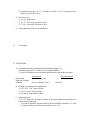
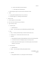
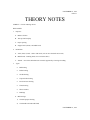
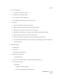
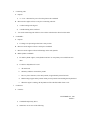
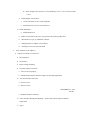
18.
Label the parts of the camshaft lobe:
• A: Nose
• B: Flank
• C: Clearance Ramp
• D: Heel
• E: Base Circle
• F: Cam Lift
19.
Give a brief description of the parts that make up the camshaft lobe.
• Nose: Determines duration of max life
• Flank: Determines the acceleration of opening and closing the valve
• Clearance Ramp: Acts as a shock absorber when gently opening and closing the valve
• Heel: Area that allows the valve to close
• Base Circle: Forms the base of the cam – constant radius from the centerline of the journal to
heel.
20.
What are 2 camshaft manufacturing methods?
• Cast
• Billet
21.
List 3 different types of camshaft drives:
• Chain
• Belt
• Gear
22.
List 3 different types of cam chain tensioners:
• Manual
• Semi-automatic
• Automatic
4-stroke operation, Cylinder heads, and Valves
1.
List the 5 factors that determine and engines efficiency and give a brief description of each.
• Volumetric Efficiency – Percentage ratio comparing how much air/fuel enters the engine to
how much the engine would hold if it were 100% full.
• Combustion Efficiency – Percentage ratio comparing how much of the engines original
air/fuel mixture has completed the entire combustion process.
• Thermal Efficiency – Percentage ratio comparing how much heat the engine produces to how
much is used to produce power.
• Stroke Efficiency – Percentage ratio comparing how far the piston travels under useful
pressure to the total distance it travels.
• Mechanical Efficiency – Percentage ratio comparing how much power is produced to how
much is lost.
2.
Give a brief description of :
• Stroke: Piston travel from dead center to dead center (top to bottom, or vise versa)
• Top Dead Center (TDC): The point at which the piston is the furthest distance from the
crankshaft.
• Bottom Dead Center (BDC): The point at which the piston is closest to the crank.
3.
What do these abbreviation represent?
• BTDC: Before Top Dead Center
• BBDC: Before Bottom Dead Center
• ATDC: After Top Dead Center
• ABDC: After Bottom Dead Center
• TDCC: Top Dead Center Compression
4.
What are the 5 events (in order) of a 4-stroke engine?
• Intake
• Compression
• Ignition
• Power
• Exhaust
5.
How many strokes does the piston make to complete these 5 events?
• 4 strokes
6.
How many revolutions does the crankshaft make to complete all 5 events?
• 2 revolutions
7.
How many revolutions does the camshaft make to complete all 5 events?
• 1 revolution
8.
Why does timed ignition occur before TDC?
• To allow for combustion lag.
9.
When and on what stroke does the intake vale open and close?
• Opens: BTDC on the exhaust stroke
• Closes: ABDC on the compression stroke
10.
When and on what stroke does the exhaust valve open and close?
• Opens: BBDC on the power stroke
• Closes: ATDC on the intake stroke
11.
What is scavenging?
•
Removing of exhaust gases from the cylinder
12.
Why is it important to time the camshaft with the crankshaft?
• Valves may contact one another or the piston crown if not timed.
13.
When does Valve overlap occur?
• Valve overlap occurs BTDC on the exhaust stroke and ends ATDC on the intake stroke.
14.
What are some advantages of having valve overlap?
• Better scavenging
• Better power
• More cooling
• More intake gas/air mixture can enter the chamber
15.
What are some disadvantages to valve overlap?
• Emissions
• Lower fuel mileage
• Loss of Torque and HP in the low and midrange
16.
Why is Aluminum a good material to use in the construction of motorcycle engines?
• Lighter and cools 2~2.5 times better than cast iron.
17.
What is the function of the squish area of a cylinder head?
• Increases combustion efficiency
• Forces the air/fuel mixture into a tighter pocket
• Helps mix the air/fuel more evenly
18.
What is the purpose of the poppet valve?
• Controls the flow of gases
• Transfers heat
• Forms seal for combustion chamber
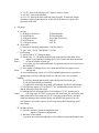
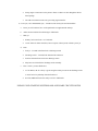
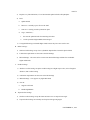
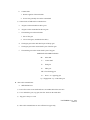
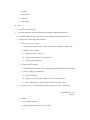
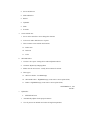
19.
Label the parts of this poppet valve:
• A: tip
• B: keeper groove
• C: stem
• D: neck (weld area)
• E: face
• F: margin
20.
List the purpose of these areas that make up the poppet valve.
• Tip – area that rides against the opening device
• Keeper groove – groove that locks the keeper and spring retainer
• Stem – thrust surface for the valve guide
• Face – area that mates to the valve seat
• Margin – supports the face
21.
Which valves will normally provide the larger valve area for the airflow?
• The intake valve(s)
22.
Where is Stellite used, and why?
• Tip and Face – to help with wear
23.
What areas of the valve should be closely inspected for wear?
• Tip
• Keeper Groove
• Stem
• Face
24.
What does the face of the valve seat against?
• Valve seat
25.
What can cylinder head valve seats be constructed of and why?
• Hard alloy steal to deal with heavy wear
26.
What is the purpose of having 3 different angle on the cylinder head valve seat?
• Better flow characteristics
27.
What is the bushing that is used to support the valve called, and what is its construction?
• Valve guide – can be made of either Cast Iron or Brass
28.
The purpose of the valve stem seal is?
• Prevent excessive oil from entering between the valve guide and the valve stem.
Air and Fuel Delivery Systems
1.
The purpose of the before and after carburetor air/fuel delivery system is to:
• Before: store and deliver proper amounts of air and fuel
• After: deliver air/fuel to the engine
2.
If fuel is to flow from the fuel tank, the fuel tank must be vented to atmospheric
pressure.
3.
Some states, such as California, require the fuel tank be vented into a charcoal
canister.
4.
What is the purpose of the fuel valve (petcock)?
• Delivers fuel from the tank to the carbs.
5.
Name 4 different petcock styles used on motorcycles:
• Manual
• Vacuum
• Electric
• Vacuum with electric assist
6.
What is the RES position used for on the petcock?
• To flow fuel to the carbs from a position in the tank lower than the pick-up for
the main, or ON, position.
7.
How does a vacuum type petcock operate?
• Allows fuel flow only when the engine is running (there’s a vacuum present)
8.
What is the PRI (prime) position used for on a vacuum type petcock?
• It flows fuel with no vacuum present (all the time)
9.
What is the purpose of the fuel pump?
• To deliver fuel from the fuel tank to the carbs/fuel injection.
10.
What are 3 types of fuel pumps used on motorcycles?
• Mechanical
• Vacuum
• Electric
11.
What is the purpose of the fuel filter?
• Filter crud from the fuel before getting to the carbs.
12.
What is the purpose of the air filter?
• Filter crud from the air before getting to the carbs.
13.
Name 3 types of common air filters:
• Paper
• Gauze w/oil
• Foam w/oil
14.
What can happen (to engine operation) if one type of air cleaner is substituted for
another filter of different construction that allows a different amount of air to
flow?
• It can create a rich or lean running condition
15.
What are the purposes of the intake manifold?
• Deliver air/fuel to the engine
• Secure the carb to the engine
• Make up the intake tuned length
16.
Name 3 types of carb mounts and briefly describe each:
• Spigot – carb fits inside manifold boot
• Flange – carb bolts directly to the head
• Clamp-on – carb fits over manifold boot.
Batteries
1. Purposes:
A. Provide initial power to start motorcycles, and run accessories when engine is off
B. Provide energy when engine is idling
C. Buffer out voltage surges, spikes (captive action)
2. How:
A. Stores electrical energy in chemical form
B. Upon request, converts chemical energy back to electrical energy
C. This electrochemical change is NOT 100% efficient
3. Types of Batteries found on motorcycles
A. Conventional
1) Paper of fiberglass separators
2) Fewer total plates
3) Requires frequent water replacement
B. Low-maintenance
1) Separators of thinner, denser, synthetic material
2) More total plates
3) More cranking power
4) Less frequent water replacement
C. Maintenance free
1) Recombinant technology
2) Special plates and electrolyte
3) About the same cranking power as a low-maintenance
4) Permanently sealed – no water replacement required
4. Battery Cells
A. Each cell stores 2.1-2.2V
B. Construction
1) negative plates
a) lead
b) Grey in color
2) positive plates
a) lead peroxide
b) reddish brown in color
3) separator sheet
a) porous material
b) insulates the negative and positive plates from each other
4) electrolyte
a) a mix of diluted sulfuric acid and distilled water
5) case
a) contains all parts of the cells
b) usually made of plastic or hard rubber
C. Plate arrangement
1) in each cell, plates are wired in parallel
2) each plate increases the current, while the voltage remains the same
D. Cell arrangement
1) Cells are wired in series
2) Each cell increases the total voltage output while current remains the same
a) 12v battery has 6 cells
b) 6v battery has 3 cells
E. Ohms Law
1) Size of cell affects current, but not voltage
2) Number of cells affects voltage, but not current
5. Discharging
A. The electrolyte breaks down, forming water and sulfuric acid
1) Sulfuric acid combines on the negative plates and forms lead sulfate
2) After a time, buildup becomes visible as a white crystalline substance called ‘sulphation’
B. Plain water is left on the positive plates
1) electrolyte becomes similar to water and is prone to freezing
2) A dead battery will freeze at 20degrees F.
6. Recharging
A. The chemical process is reversed
B. Bubbles visible during charging
1) excess hydrogen and oxygen that could not remix
2) ‘Free-gassing’ (or hydrogenating)
3) reason batteries are vented
4) Danger: Hydrogen and oxygen gasses given off during free-gassing are highly explosive
C. With electrolyte in full suspension, fully charged lead/acid batteries resist freezing down to about –
75degrees F.
7. Ampere-hour rating
A. Battery ability to deliver current
1) for a period of time before it reaches a state of discharge
2) 12v battery state of discharge is 10.5v
B. Time period for motorcycle batteries
1) usually 10 hours
2) 14 ampere/hour batter, before reaching a state of discharge
a) delivers 1.4 amps for 10 hours
b) delivers 14 amps for 1 hours
c) delivers 1 amp for 14 hours
8. Effect of temperature on batteries
A. Inactive batteries discharge
1) Conventional batteries = .5 to 1% daily at an atmospheric temp of 77degrees F
2) Low-maintenance/MF = .15 to .3% daily at an atmospheric temp of 77degrees F
B. Cold slows down the chemical action and causes a slower discharge rate
C. Heat and humidity speed the chemical action and causes a higher rate of discharge
D. When not being used, store batteries in a cool, dry place
9. Factors affecting battery performance
A. Anything that increases the motors resistance to turning or starting
1) Poor engine tune, cold oil, worn starter
2) Example: a 1000watt starter, 13.5v available
a) at 13.5v, amps required = 74 - 1000/13.5 = 74
b) as the starters load increases, available voltage drops, making demand for amps increase – at 11V,
amps required = 91 - 1000/11 = 91
c) Result: batteries capacity (ampere/hour rating) fixed but current requirement increased, battery
drains sooner
B. Battery’s state of charge: a low battery has less cranking power than a charged one
C. Water level in each cell: without sufficient electrolyte the battery can’t efficiently convert chemical
energy to electrical energy
D. Temperature:
1) cold weather reduces/retards the chemical reaction, reducing performance
2) Overheating can increase corrosion of plates, or cause plates to warp.
E. Vibration: excessive vibration can shake off active material from plates, reducing battery life, cell
capacity and shortening cells
Charging Systems
1. AC charging system
A. Purpose is to maintain a fully charged battery
B. Components
1) AC generator
a) Rotor
(1) permanent magnet, or
(2) electromagnet
b) stator
(1) ½ wave, or
(2) full wave, or
(3) three phase
2) Rectifier
a) 1-diode, or
b) 4-diode, or
c) 6 (or more) diode
3) Regulator
a) suitable for permanent magnet system, or
b) suitable for electromagnet system
4) Battery
2. Function
A. Ac Generator
1. Major parts: stator and rotor
a) stator = conductor, stationary
b) rotor = magnets, rotating
2. Major divisions, by charge curve and control
a) permanent magnet
(1) rotor is permanent magnet type
(2) charging curve abrupt, moderate
(3) regulator controls voltage by switching in to out (gating to ground) parts of the stator
b) excited field (electromagnet)
(1) rotor is electromagnet type
(2) charging curve is gradual, high power
(3) regulator controls charge by varying magnetic strength of rotor
B. Rectifier
1) Converts alternating current (AC ) to direct current (DC)
2) Uses diodes
C. Regulator
1) Regulates charging system output to protect battery and electrical components
2) Does this, depending on whether permanent magnet or electromagnet, by:
a) gating excess current to ground (draining off part of stator(, or
b) by moderating voltage to the field coil (rotor), thereby changing the strength of it’s magnetism
D. Battery
1. stores DC
2. Acts as a buffer between charging system and electrical components
3. Powers components at low RPM, when charging system output is low
E. Three charging system designs, based on output
1. ½ wave system
a) small charging coil, grounded on one side, other goes to rectifier
b) very low, pulsating output
2. Full wave system
a) Both ends of the larger charging coil go to the rectifier
b) Moderate output
3. Three phase system
a) 3 interconnected charging coils, 3 coil leads going to the rectifier
b) high, smooth output
Clutches
1.
What is the purpose of the clutch?
• To engage and interrupt power flow from the engine to the transmission.
2.
What are 5 types of clutches?
• Manual
• Centrifugal
• Variable ratio
• Sprag
• Torque converter
3.
How is a manual clutch engaged and disengaged?
• Typically by the rider pulling on a lever on the handlebar
4.
What types of friction material are used on a wet clutch?
• Cork/neoprene, paper, or kevlar
5.
What types of friction material are used on a dry clutch?
• Kevlar or organic
6.
What part of the multi-plate clutch is usually driven by the engine crankshaft?
• Outer basket
7.
What shaft do most clutch baskets rotate (free wheel) on?
• Transmission driveshaft
8.
What is the purpose of a shock hub found on the back of some clutch baskets?
• Absorbs excess power (reduces harshness in power change)
9.
What plate is attached to, and driven by the outer basket?
• Drive plates
10.
What plate is attached to the inner hub?
• Driven plates
11.
What is the inner hub splined or fastened to?
• Transmission drive shaft
12.
What applys spring pressure to the disk stack when the clutch is engaged?
• Pressure plate
13.
What 3 types of springs are most commonly used to squeeze the clutch plates
together?
• Coil spring
• Diaphragm
• Tension
14.
What is the power flow through the clutch with the clutch engaged?
• Engine to outer basket to drive plates to driven plates to inner hub to
transmission shaft
15.
What is the power flow through the clutch with the clutch disengaged?
• Engine to outer basket to drive plates
16.
Define clutch slippage
• Clutch doesn’t transfer 100% power
17.
What could cause clutch slippage?
• Improper adjustment or assembly
• Weak clutch springs
• Worn drive or driven plates
18.
Define clutch drag
• Clutch doesn’t fully disengage
19.
What could cause the clutch to drag?
• Warped metal plates
• Worn outer basket or inner hub
• Improper adjustment
20.
Name the 7 types of clutch release mechanisms
• Rocker arm
• Ball and ramp
• Rack and pinion
• Lever
• Cam
• Screw
• Hydraulic
21.
What type of clutch uses weights, springs and engine RPM to engage and
disengage power flow (no clutch level)?
• Centrifugal
22.
Why do some centrifugal clutches have a manual release mechanism built into
them?
• To allow for engine breaking when off-throttle
23.
What is the purpose of the variable ration clutch?
• To always have the engine in the meat of the power band
24.
What is a sprag clutch and where can it be used?
• Clutch that engages in one direction only – used in starter motors and some
high-HP main clutches.
Constant Velocity (Vacuum) Carburetors
1.
Why is the CV carb used on just about every street motorcycle today?
• It delivers only the air/fuel that the engine can use and compensates slightly
for changes in altitude.
2.
How is the slide movement controlled in a CV carb?
• Moved by pressure differences
3.
What is the hand throttle controlling on a CV carb?
• The throttle plate
4.
How does the low-pressure air get to the top of the slide?
• Through a hole in the slide (pressure passage)
5.
What is used in the CV carb to keep the vacuum and atmospheric pressure
separated (on the slide)?
• Rubber diaphragm
• Metal piston
6.
Where is the idle outlet port located on CV and fixed venturi carbs?
• Engine side of the throttle plate
7.
Where are the by-pass ports located on CV and fixed venturi carbs?
• On the air filter side of the throttle plate
8.
On variable venturi carbs, the jet needle and needle jet are used to vary the
midrange flow of fuel.
9.
The midrange circuit in variable venturi carbs will share an air bleed passage
with the main jet circuit, which is used to atomize the fuel.
Cooling Systems
1.
What is the purpose of the cooling system?
• Rid engine of excessive heat
• Allow the engine to operate in a specific temperature range
2.
What are 3 types of motorcycle cooling systems?
• Internal
• Air
• Liquid
3.
What would an advantage be of forced draft air-cooled over open draft?
• Cooling even when stopped.
4.
Explain the purpose of these components in a liquid cooled engine:
• Water pump: circulate the coolant
• Inspection hole: inspect water-pump seal
• Thermostat: allows for quicker warm-up and operation at a specific
temperature
• Radiator: heat exchanger
• Radiator cap: seals the system and determines system pressure
• Radiator fan: draws air through the radiator
5.
Why is distilled water used in cooling systems rather than tap water?
• Doesn’t have any mineral deposits
6.
What type of coolant/anti-freeze is used in most cooling systems, and what is it’s
purpose
• Ethylene or Propylene glycol – and it lowers the freezing point of water, as
well as raises the boiling point
7.
What is the normal ration of coolant to distilled water?
• 50:50
Electrical Currents
1. Circuits
A. Complete path for current to flow
B. From source and back through the path of least resistance (a circle)
2. Four requirements for a functioning circuit
A. Source, or EMF (voltage)
1) Battery, or
2) Charging system, or
3) AC source coil
B. Complete Path
1) Path for current to flow from source to load, and from load back to source
2) Wire or motorcycle frame
C. Load device
1) Device the converts electrical energy to some other form of energy
a) light
b) horn
c) coil of wire (heating element or Electro-magnet)
2) All load devices have some resistance
D. Means of control
1) Device that controls or limits total current flow
2) Switch
3. Circuit Protection
A. Fuses and circuit breakers
1) Fuses and circuit breakers are circuit protection devices
2) Excessive current flow causes excessive heat which result in ‘blown’ fuses and ‘tripped’ circuit
breakers
4. Circuit types
A. Series circuit: only one path for current to flow
B. Parallel circuit: more than one current path
C. Series/parallel circuit
1) Circuit with a series section through which current must flow before branching out into the legs of a
parallel circuit.
2) Example: A charging system is a series/parallel circuit, with the battery in series.
5. Unwanted circuit conditions
A. Open circuit
1) Incomplete path for the current to flow (no continuity)
2) Symptoms: components will not work
3) Examples: broken wire, blown fuse, open switch
B. Grounded Circuit (unwanted)
1) Circuit that has developed a path for current to flow back to its source, After the load device, but
before the means of control
2) Symptom: loss of means of control
3) Example: if a horn circuit develops an unwanted ground before the switch, the horn will activate
continuously
C. Short circuit
1) Circuit that has a path for current to flow back to the source, Before the load device
2) Takes the resistance out of the circuit
3) Symptoms
a) Blown fuse
b) Excessive heat and damage to wiring harness and/or other components. Particularly if a circuit
doesn’t use a protection device.
6. Voltage Drop
A. The amount of voltage used between two points
B. If there’s more that one load in a circuit, part of the voltage will drop across each load
C.
1)
2)
D.
Purpose of measuring voltage drop:
Helps in troubleshooting by locating unwanted resistance
More accurate than a resistance test
Sum of all individual voltage drops will equal the applied source voltage
Electrical Terminology
1. Electricity
A. The flow of electrons through a conductor
2. Atom: smallest part of whole matter
A. The basic parts
1) Proton
a) Positively charged particle
b) Found in the nucleus
2) Neutron
a) Particle that has NO charge
b) Found in the nucleus
c) Neutrons add weight and occupy space
3) Electron
a) Negatively charged particle
b) Orbits the nucleus
c) Orbit is called a ‘shell’
i)
Outermost shell is called the ‘Valence Shell’
ii)
electrons in the valence shell are valence electrons
iii)
Valence electrons my be enticed to leave the shell
3. Electromotive Force (EMF)
A. Electrical pressure
1) The force that induces the valence electrons to move
a) NOT the movement itself
2) Voltage
3) Potential difference
a) electrical equivalent of pressure difference
b) Imbalance of electrical charge between 2 points
c) Voltage difference between two points in an electrical circuit
B. Created By
1) heat
2) friction
3) chemicals
4) magnietisim
4. Continuity
A. The ability of a component, switch, fuse, wire.. etc. to flow current
B. “Go/No go”: Continuity is NOT a measurement, the component is either continuous or it isn’t
C. Examples:
1) an open switch has no continuity
2) a closed switch has continuity
3) a good fuse has continuity
4) a bad fuse has no continuity
5. Conductor
A. A material that allows free movement of electrons (allows electrical flow)
1) Conductors have three or fewer valence electrons
2) These electrons leave their shell easily
B. Examples of good conductors
1) Gold
2) Silver
3) Copper
4) Aluminum
5) Steel
6.
A.
1)
2)
B.
1)
2)
3)
7.
A.
1)
2)
B.
1)
2)
3)
C.
1)
a)
b)
c)
2)
a)
b)
3)
a)
b)
8.
A.
B.
Insulator
Material that does NOT allow for free movement of valence electrons
Insulators have 5 or more valence electrons
These electrons are reluctant to leave their shell
Examples of insulators
Rubber
Plastic
Air
Semi-conductor
Manmade substance who’s electrical conductivity is between that of an insulator and a conductor
depending on the conditions.
Semi-conductors have 4 valence electrons
Can instantly be signaled to convert to 5 or 3 valence electrons
Semi-conductor material examples:
Silicon – most common
Germanium – older
Selenium – obsolete
Examples of semi-conductors used on motorcycles
Diode
Two leads
Flows current in one direction
Blocks flow in opposite direction
Transistor
Three leads
A fast, low current switch
Silicon controlled rectifier
Three leads
A slower, high current switch
Current
The rate of FLOW of electricity
Measured in amperes (Amps)
1)
2)
9.
A.
B.
C.
1)
2)
D.
10.
A.
1 AMP = 1 Coulomb / 1 Second
A coulomb is 6.24 x 10^18 electrons
So, 1 amp is a flow of 6.24 x 10^18 electrons per second (6,240,000,000,000,000,000 electrons)
Resistance
Opposition to current flow (electrical ‘friction’)
Measured in Ohms
The higher the opposition to current flow, the higher the resistance
A component with 4 Ohms of resistance permits a lot of current flow
A component with 10 Ohms of resistance permits less current flow
A switch, wire or fuse in good condition has 0 Ohms of resistance
Watt
A measurement of electrical power
(Force x Distance [work]) / Time = Power
(Pound [force] x Feet [distance]) {Torque} / Seconds [time] = Horse Power
Volt [force] x (Coulomb [distance] / Second [time]) {amp} = Watt [power]
1 Volt x 1 Amp = 1 Watt
E = EMF – VOLT – Pressure
I = Intensity – AMP – Rate of flow
R = Resistance – Ohms
P = Power – WATTS – Electrical H.P.
11. Polarity
A. Direction of current flow
B. Derived from the word ‘Pole’
12. Direct Current (DC)
A. Current that flows in one direction only
B. Example: Battery current is DC
C. DC flow theories
1) Conventional
a) Oldest and most accepted in the motor vehicle trades
b) Idea that current flows from positive to negative
c) From battery positive terminal, through circuits and back to battery negative terminal
d) Theory used by MMI
2) Electron Theory
a) Used mostly by electronic technicians
b) Idea that current flows from the negative to the positive
13. Alternating current (AC)
A. Current whose polarity alternates, i.e. – flows one way, then the other
B. Motorcycle charging systems generate AC
C. Induction
1) Magnetic field
2) Conductor (coil of wire)
3) Motion (of conductor OR magnetic field)
Fixed Venturi Carburetors
1.
Name 2 main differences in fixed venture carbs as compared to variable venturi
carbs:
• Fixed venturi
• Throttle plate regulates airflow
2.
What controls the airflow in a fixed venturi carb?
• Throttle plate
3.
Where is the idle outlet port located on a fixed venturi carb?
• Engine side of the throttle plate
4.
Where are the by-pass ports located on a fixed venturi carb?
• Air cleaner side of the throttle plate
5.
In a fixed venturi carb used on a street motorcycle, what 3 things will aid in
transition from idle to mid-range?
• By-pass ports
• Accelerator pump
• mid-range ports
6.
If the fixed venturi carb has a mid-range circuit, what is used to meter the fuel
during midrange operation?
• A brass jet or precisely drilled hole
7.
What is the purpose of the emulsion tube?
• Aid in fuel/air atomization
8.
If the fixed venturi carb has a midrange circuit, where is the midrange outlet port
located?
• Air cleaner side of the throttle plate, between the by-pass outlet ports and the
main outlet port.
9.
In a fixed venturi carb, where is the main outlet nozzle located?
• In the center of the venturi
Float Bowl Circuit
1.
What is the purpose of the float bowl circuit used in most carbs?
• To maintain a constant level of fuel in the float bowl at all engine RPMs
2.
What carb circuits does the fuel level in the float circuit effect?
• ALL
3.
A high fuel level in the float circuit will cause what type of air/fuel mixture?
• Rich
4.
A low level of fuel in the float circuit will cause what type of air/fuel mixture?
• Lean
5.
Name 3 float bowl locations, in relation to the venturi:
• Concentric (directly underneath)
• Eccentric (off to one side)
• Remote
6.
What is the purpose of the float bowl overflow tube?
• Prevents fuel from flooding the engine in the event that the float stuck open.
7.
What does the float push against to control the flow into the float bowl?
• Float needle
8.
To operate properly, the float bowl must be vented to the atmosphere.
9.
How is the level of the fuels (and float height) changed on adjustable floats?
• By bending the tang
10.
What are the 2 parts of the float valve assembly?
• Float needle
• Float needle seat
11.
What is the purpose of the spring loaded pin on the float needle?
• Acts as a shock absorber between the float needle and float tang
12.
What are the 2 most common methods of measuring the level of fuel in the float
bowl?
• Measuring float level
• Measuring fuel level
13.
A higher than normal float measurement will result in low fuel level and a lean
air/fuel mixture to all circuits.
14.
A lower than normal float measurement will result in a high fuel level and a rich
air/fuel mixture to all circuits.
15.
Some carbs use a diaphragm instead of a float bowl – Why?
• It can operate at any angle
Friction Reducing Devices
1.
What are some purposes of bearing and bushings?
• Reduces friction
• Takes up shaft end play
• Proper spacing
• Support axial and radial loads
2.
What are axial (thrust) loads?
• Side to side loads
3.
What are radial loads?
• Rotational loads
4.
What is a ‘journal’?
• Area of shaft that turns on, or is supported by a bearing or bushing
5.
Name 4 types of rolling element bearings
• Ball bearing
• Needle bearing
• Roller bearing
• Tapered roller bearing
6.
Which of these 4 bearings can handle radial loads, but only thrust loads in one
direction?
• Tapered roller bearings
7.
Which of these bearings can handle radial and axial loads in both directions?
• Ball bearings
8.
Which of the 2 anti-friction bearings can only take radial loads?
• Needle bearings
• Plain bearings
9.
What is an advantage of a caged bearing over an uncaged bearing?
• Can support higher RPM
10.
What type of bearing requires a thin layer of oil between it and the rotating
surface, and usually comes in matched pairs?
• Plain bearing
11.
What is ‘imbedability’?
• The ability to imbed small amounts of material
12.
What are the purposes of thrust washers and bearings?
• Support axial loads and reduce shaft end play
13.
What is the main difference between a thrust washer and thrust bearing?
• Thrust bearing has rollers
14.
What is a bushing?
• Soft alloy that works similar to a plain bearing.
Fuels & Air/Fuel Mixture Requirements and Air Density
1.
What is the importance of a fuels octane rating?
• Measurement of the ability to resist detonation
2.
What are some factors that can influence the octane requirements of an engine?
• Air temperature
• Altitude
• Humidity
• Ignition timing
• Jetting
• Method of riding
• Engine compression ration
3.
Gasoline is basically made up of Hydrogen and Carbon atoms called
hydrocarbons.
4.
3 types of gasoline are:
• leaded
• unleaded
• oxygenated
5.
Why has leaded gasoline been replaced?
• EPA regulations due to pollution
6.
What are 2 additives used to increase unleaded fuels quality?
• Iso-octane
• Heptane
7.
What is the main purpose of oxygenated fuels?
• Burns cleaner and raises octane rating
8.
What are the 3 most common additives in oxygenated fuels?
• Ethanol
• Methanol
• MTBE
9.
What are some advantages of using gasohol?
• Burns cleaner
• Raises octane rating
• Good deicer
10.
What are some disadvantages of using gasohol?
• Absorbs water
• Can harm rubber/cork and plastic fuel components
• Can cause leanness
11.
Air/fuel ratio can be defined as:
• A ratio, be weight, of parts of air to one part fuel
12.
What air/fuel ratio does the theoretical perfect combustion of gasoline take place?
• 14.7:1
13.
An air/fuel mixture of 17:1 would be considered a lean mixture
14.
An air/fuel mixture of 12:1 would be considered a rich mixture
15.
Cold starts require an air/fuel mixture of 10:1 or less, why?
• Fuel doesn’t vaporize as well
16.
At idle, the engine requires and air/fuel mixture of approximately 10:1, why?
• Poor vaporization due to low air-flow
17.
Mid-range riding conditions will require an air/fuel mixture of approximately
17:1, why?
• For better fuel economy and cleaner emissions
18.
To achieve best power and aid in cooling, an air/fuel mixture of approximately
13:1 would be required.
19.
Define air density:
• The amount of oxygen molecules per given space
20.
What are 3 factors that can affect air density?
• Temperature
• Altitude
• Humidity
21.
If air density increases enough, the carburetor must be jetted richer by increasing
the jet size.
Gears, Gear Ratios and Primary Drives
1.
What is a gear?
• A rotating lever
2.
How is gear speed measured?
• Measured in RPM
3.
What is the force behind a moving gear?
• Torque (= force * distance from pivot)
4.
List 5 ways a gear can be used (purposes):
• To transmit power
• To change direction of rotation
• To increase torque (which decreases RPM)
• To increase RPM (which decreases torque)
• For timing
5.
Gear ratio can be defined as:
• Numerical comparison of the number of revolutions of a drive gear to one
revolution of a driven gear.
6.
What is the basic gear ratio formula?
• Number of teeth on driven gear / number of teeth on drive gear
7.
An underdrive will have a ratio that is numerically:
• Greater than 1:1
8.
A direct drive will have a ratio that is:
• 1:1
9.
An overdrive will have a ratio that is numerically:
• Less than 1:1
10.
What’s the formula for determining that primary drive ratio?
• Number of teeth on clutch / number of teeth on crankshaft
11.
What is the formula for determining the transmission gear ratio on most
transmissions?
• Number of teeth on countershaft / number of teeth on main shaft
12.
What is the formula for determining the final drive ratio on chain or belt driven
motorcycles?
• Number of teeth on rear wheel / number of teeth on transmission sprocket
13.
What is the formula for determining the final drive ratio on a shaft final drive
motorcycle?
• Number of teeth on ring gear / number of teeth on pinion
14.
What type of gear is used when shafts are at 90degree’s to one another?
• Bevel
15.
What is an advantage of a spur gear?
• Inexpensive and no side loads
16.
What is an advantage of a helical gear over a spur gear?
• Quieter and stronger than spur gears
17.
What is the purpose of an idler gear?
• To change the direction of rotation
18.
Name 3 types of gears that can be used in primary drives:
• Spur
• Offset spur
• Helical
19.
What type of belt is used in primary drives?
• Gilmer belt (toothed)
20.
Name 4 types of chains that can be found in primary drives:
• Single row
• Double row
• Triple row
• Hi-vo
21.
Some motorcycles use a primary shaft in the primary drive. What can it be used
for?
• Drive the clutch, change direction of rotation, or operate a charging system.
GENERAL
1. 66-69, generator bottom end. 70-84, AC generator (cone motor) (magnet spins
around windings)
2. Installation of engine (right side)
A). rock motor corner to corner to check fit.
B). torque down rear motor mount
C). check front mount and frame for clearance (shim any clearance), than torque front
mount
D). inspect clearance between top mount and frame. shim for “0” clearance, than
torque.
3. Engine and tranny proceedure
A). install engine
B). loosely bolt primary to engine
C). with tranny and plate loose, bolt primary to tranny
D). shim primary than torque engine and primary. than torque tranny and primary
E). torque tranny and plate
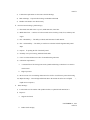
4. Rocker box installation torque pattern
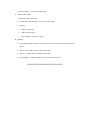
5.
Head bolt installation torque pattern
6. Rocker box
A. Cut out provides clearance between cover and frame when engine is hot
1). engine expands approxamately .040” (measured from cylinder deck to top of
rocker box).
B. Rocker shaft location, 1 degree negative angle places rocker arm lower on valve
side. spins valve to prevent lead build up, quieter, supposed to keep arm thrusted
to one side
C. Gasket- torque to 12-15 ft-lbs. 300 percent increase when engine reaches
operating temperature. assemble dry or with lithium grease (H-D says dry).
D. Max warpage- .006”
E. 78 1/2 late style rocker box. Boss under front for “ham can” mounting and
shortened boss on back left side using shorter stud.
F. Rocker arms (2 types)
1). front exhaust/ rear intake and front intake/ rear exhaust
2). case hardened, max wear or pitting, more than .005”, replace (pad or socket
area)
3). 66’-70’ rocker arms were copper plated (-66 arms)
71’-up, iron arm with more even wear (-66A arms, will retro fit)
82’-up, had a ground out 1 degree to offset for negative angle in the cover(pad
area)
4). rocker arm end play
a). specs. .004”-.025” . Good is .004”-.010”
b). alter end play
(1). best method, cut a shoulder on the shaft
(2). good method, chamfer rocker arm spacer (5/8-3/4 countersink, 90
degree angle
(3).bad method, shim the rocker arm (do not do this)
5). rocker shaft
a). -66A part number if o-ring seat is square. -66B part number if o-ring seat is
beveled
b). specs. shaft to arm, .003” max clearance
shaft, .0015” max wear
shaft to box, .002” max clearance
(1). excessive clearance in these areas will cause flooding of the valve
pocket area.
c). see hand out page 3-1 for additional information
G. Pushrod
1). all 4 identical
2). inspect for:
a). damaged ends
b). damaged locknuts
c). max bend .010”
H. Pushrod Tubes
1). 79’ and earlier, cork gasket, flat edge tube
2). L79’-84 1/2’, o-ring gasket, lip edge tube. (for more compression, use cork in
place of middle o-ring).
7. CYLINDER HEADS
A. Specs.
1). head gasket surface, max warpage of .006”
2). head gasket types, Teflon = blue, Graphite = black, Metal fiber = gray (James
gasket with metal fire ring and silicon bead). Install all gaskets dry
3). torque- 55-75 ft-lbs. staged, 30,45,55. (always start next to oil hole).
DO NOT GO OVER 65 FT-LBS. TOTAL, ALUMINUM.
4). fire ring height causes leaking or blown head gasket when excessive .010”
clearance between head and cylinder
5). head bolt should be assembled with lube or “never seize”
6). additional information on page 3-2 of hand out
B. Cylinder prep for re-assembly
1). clean in soapy water
2). clean and lube with a paper towel and motor oil (light weight)
3). clean drain hole with a brush
C. 1980 heads
1). cast iron guides, longer with shoulder
2). head has machined surface for new style lower valve spring collar. collar
now rests on head surface instead of valve guide shoulder
3). L81
a). cst iron guides, longer with shoulder
b). ream or hone for proper clearance, intake = .0015”, exhaust = .0025”
c). valve guide seals- umbrella type seals
NOTE- do not use loctite on a valve guide seal
D. Valves
1). hard valves- Eaton, hard chrome, US made.
Nittan, black nitride coating, Japan made.
2). stem diameter- 80’ valve diameter same as earlier models. 81’ valve is
approximately .003” larger stem OD
3). 80 and 81 valves are recommended for use with all cast iron guides
4). medium hard valves, -57A and -66 valves are compatible with cast iron guides
but not recommended due to short service life
5). soft valves, -57,-60 valves, never use soft valves with cast iron guides. (causes
valve sticking).
E. Springs and hardware
1). spring ID- silver = 82’ and earlier, red/orange = L82-84 (prevents coil bind
with “S” cam)
2). top retainer- mid 81 and earlier, thicker. L81 and up, .050” thinner for seal
clearance
3). bottom collar- 79 and earlier, 9/16 ID. sits on guide shoulder
L81 and up, 3/4 ID. fits over seal, sits on head surface
F. Cylinders. cast iron all years. 1200cc = 3 7/16 bore. 1340cc = 3 1/2” bore.
1). 66’ -78’,1200cc, 10 fins with a thin base. (available untill 80’ as an option).
2). 78 1/2 and up, 1340cc, 9 fins with a thick base. (1200cc option)
a). base is cut out for triangle washers, round side faces down.
3).when boring or honing, use torque plates and gaskets.
4). cylinder inspection:
a). base surface, .003” max warpage.
b). wear limits, max clearance, .006” cylinder to piston (.0015”-.003” good)
max taper, .002”
max out of round, .001”
c). finish #240 plateau ( when sizing cylinder, use torque plates and gaskets)
G. Pistons
1). 60’-83’, Bohnalite, USA made, H-D machined, cast in steel strut (controls
expansion), tin coated for break in, symetric, no wrist pin offset, wrist pin clips
72’-77’, spirolox and 77’ and up use Tru arc (pistons will be marked with -78
part number or “77” cast into piston). can use a spirolox in a Tru arc piston,
but not the reverse.
2). compression ratio:
a). 1200cc, high compression 8:1, FLH, (round dimple in crown)
b). 1200cc, low compression 7.4:1, FL, (no dimple)
c). 1340cc, high compression 8:1, FLH, (rough crown)
d). 1340cc, low compression 7.4:1, FL, (smooth crown)
3). wrist pin (see service bulletin- hand out page 3-15)
a).-74 pistons have lowered wrist pin locations for use with .030” shorter
connecting rods
b). -53 and -55 pistons have higher wrist pin location for use with longer rods.
(-36 and -41A)
4). piston clearance: .001”-.002” with a max of .006”
5). Mahle pistons-L83’-84’
a). German made
b). very hard (12% silicone content)
c). approximately 100 grams lighter than Bohnalite
d). wire type pin clip (use special Kent-Moore tool to install) gap at 12:00
e). wrist pin offset closer to rear of piston
(1). arrow faces forward
(2). lug (under skirt to left)
(3). pin closer to rear
6). Mahle piston shape
a). diamond turned process (barrel faced)
b). can retro fit to all 1340cc shovel head engines
c). things in common with the EVO; rings, pins,clips. nly difference is shovel
pistons are domed, Evo are flat top
7). rings
a). 3 piece oil control, 1340cc, Dec. 78 and later, 1200cc, Jan. 79 and later
b). 3 piece oil control set features:
(1). top ring: barrel face
(2). 2nd ring: reverse twist taper face, scrapes on the way down, twists and
hydroplanes on the way up
(3). bottom ring: 3 piece, rails top and bottom, expander in the middle.
less cylinder wall tension than 1 piece ring, faster break in)
(i). L78’ and earlier engines use 1 piece cast iron oil control ring and 2
chrome plated compression rings.
(4). 3 piece set will retro to earlier pistons
H. Tappet guides
1). 4 variations
a).66’-76 1/2, 1 small drain hole, countersunk screw holes
b). 76 1/2’-E81’, small drain hole, straight screw holes
c). L81’-E82”, no drain holes, had spigot for evacuator
d). L82’ and up, 2 transfer holes, no spigot
2). inspection
a). check for cracks (base of roller guides)
b). check for wear (max .002” between tappet and guide)
3). mounting screws
a). 66’-77’, 1/4 X 24
b). 74’-84’, 1/4 X 20
4). updating
a).drill both drain holes through to the bottom with a 3/32” bit (or use 1/8”)
I. Tappets (same all gears)(not including hydraulic units)
1). install with flat sides facing each other.
a). failure to install properly will prevent the exhaust from pumping up
2). inspection: .001” max tappet wear, and .0015” max roller bearing clearance
a). inspect tappet screen every time you change oil (open end down, spring
over screen)
J. Hydraulic lifter
1). lifter test
a). dissassemble lifter unit, bleed and clean with contact cleaner
b). with unit dry, manually compress and hold for 6 seconds, when released,
plunger should pop up
2). lifter problem causes
a). oil pressure, need a minimum of 12 PSI at 2000 RPM
b). oil path restriction, tappet screen blocked
c). tappet installed backwards
d). gasket misaligned at tappet guide
3). install tappet guide with installation tool in back (use every time to align
tappets with cam)
4). similar noises often mistaken for lifter problems
a). excessive rocker arm end play
b). loose cam gear fit
c). exhaust leak
d). sticking valve
e). bent pushrod
f). worn tappet roller bearing
K. Cam, Breather, and Pinion Gear
1).cam endplay must be measured before cover is removed
2). breather gear endplay: using a new gasket , feeler gauge, and a straight edge.
measure between straightedge and breather gear with the gasket in place. than
subtract .006” for gasket crush. ideal endplay is .005”-.010”
3). cam fitment (see hand out page 2-15)
a). ideal, straight, no lash
b). loose fitment, = noise, clatter
c). tight fitment = whine
d). gear tooth changes (cam, pinion, breather)
(1). E77’ and earlier, straight tooth profile
(2). L77’ and later, curved tooth profile (machined ring on side of gear)
(i). 7 gear sizes identified by color codes
(3). never mix old and new style cam, breather, or pinion parts
4). Cam types
a).”H” cam, E83’ and earlier. “S” cam, L83’ and 84’
b). “S” cam, all parts and accessories, less duration than “H” cam, more mid
range, quiter valve train (softer)
5). Gear inspection
a). lobes, discoloration and pits
b). bearing surfaces (change from INA to Torrington)
c). teeth
d). dog ear washer (installed eats down, slant towards rear)
G. 58’-72’ One shot oiling system
72’ and up, flat side bushing that lines up oil holes in the bushing with oil passage
(constant oiling)
L. Solid lifter usage
1). can ruin hydraulic type cam, it has no expansion ramp
2). solid ype lifter cams need expansion (clearance) ramps to reduce shock on cam
lobes, tappet rollers, and valve stems
3). solid lifters provide more cam lift than hydraulic lifters
M. Breather gear
1). 66’-E77’, steel, straight tooth (small nipple end)
2). L77’-E81’, steel, curved tooth (large nipple end)
3). L81’ and up, Zytel plastic, curved tooth (uses 6 slot window)
N. Pinion and oil pump gear
1). pinion, 58’-E77’, full tooth gear with straight profile
L77’-84’, half tooth gear with curved profile. color coded availability
2). inspection, space rcollar should have end play
a). check oil pump drive gear installation, install so iinner chamfer faces
flywheels
3). oil pump drive gear, 66’-72’, 5 tooth, 73’-84’, 6 tooth
4). oil pump driven gear, 66’-72’, 25 tooth (5:1 ratio), 73’-84’, 24 tooth (4:1 ratio,
better), can retro fit as a set
O. Gear case cover
1). 66’-69’, peanut style
2). 70’-72’, cone style, one shot oil flow
3). 73’-84’, cone style, full flow oil flow
P. Torque pattern for cam cover installation
Q.
Cam timing
8. LOWER END
A. commonized and pre-communized parts (hand out page 2-16)
commonized parts L81’ and later: service bulletin M829A
1). reason for change, more economical to manufacture and better fit at taper
pinion shaft
right side flywheel
crankpin
commonized
90 degree to keyway
rear cyl. advance = lazy 8
pre-commonized
135 degrees
no lazy 8
B. Changes to crankpin after commonized
1). L81’-L82’, .140” center oil hole
2). L82’-84, .090” center oil hole
3). 84’ and up, large offset oil hole
C. Connecting rods
1). 41’-73’, long rods, no longer available, if old style pistons are retained for use
with new style short rods
a). piston to flywheel clearance must be checked at BDC (should be 1/8” min)
b). compression ratio will be reduced from 8:1, to 7.6:1
2). 74’-82’, short rods with slot, .030” shorter, center to center
3). 82’-E83’, short rods with hole
4). L83’-84’, short rods offset with hole (dog leg rods), 10 times the fatigue
resistance (reduces bend and twist), wider web on female rod. requires new
flywheels with relief
9. Oil pump
A. oil type
1). 40 degrees and lower
10/40 multigrade
2). 40-80 degrees
20/50 multigrade
3). 80 degrees and up
60 weight, extra heavy
4). 80-95 degrees
SAE 60
5). 95 degrees and up
SAE 70
B. oil pressure
1). measure at operating temperature, 180-220 degrees
2). spec.: idle, 3-5 PSI, 2000 RPM, 12-35 PSI
C. Feed system
1). gravity feed to “F” fitting on pump
2). check valve: a 2-3 lb spring and ball seals pump and prevents drain down
when
engine is not running (a leaking check valve causes tank drain down and
blows
oil out of breather on start up)
a). to repair, lap seat with bead blasted Evo pushrod end (it’s the same size as
the check ball)
3). after engine is running, check valve opens and oil flows to tappet screen,
lifters,
and top end
4). lower end passasge opens at 5-10 PSI (regulating piston moves upward to
open passage), oil flows through crank case and gear case cover to pinion
bushing
a). oil flows through pinion shaft, right side flywheel and crank pin
b). the oil lubricates the rod bearings
c). splash from rods lubes the pistons, pin bushings, and lower end bearings
5). relief passage opens at 12-18 PSI (L73’-81, oil directed to return side. L81’
and up, directed to feed side relief)
6). hydrolocked oil (oil trapped above relief piston)L73’-80’, down tower to
return
(ID, large cap), 81’-E82’,to gear case (ID, small cap), 80’ and earlier, had
short piston and a rod to limit travel. L82’ has long piston to block relief hole
when not running to prevent drain down. rod deleted, long piston is its own
travel limiter. also, make a groove so oil can get to hydrolock passsage when
retro fitting
D. Breather system
1). pressures: positive, piston moving downward
negative, piston moving upwards
2). function, oil movement
a). pistons move downward,breather valve window is open and flywheel area
blows oil into the gearcase
(1). gearcase area, normally positive
(2). cylinder area, normally positive (transfers through tappet guide holes)
b). when pistons move upwards, breather window closes and a negative
pressure is created
(1). flywheel area, normally negative
c). there is a push/pull effect which helps drain oil from the top end
d). oil seperator (hole at bottom of breather trap, feeds to hole in breather
valve bore at the 5 o’clock position, connects with breather trap area. holes
align on negative pressure to draw oil from bottom of the trap)
e). hole in breather valve at 9 o’clock position is for primary oil return and
should create a minimum of 25” water vacuum in the primary at 1500 RPM
with vent line pinched (dry clutch model)
3). crankcase vent fitting, located above oil pump, connects to oil tank to prevent
excessive pressure or vacuum
4). crankcase breather fitting, lowest fitting on back of case, connected to air
cleaner to reroute vapors through the engine
5). evacuator system, used on E81”-E82’ models, hose connected pushrod tube
area to cylinders. system did not work- causing oil consumption, carbon
deposits, and pushrod tube leaks
6). typical breather and return system problems cause oil carryover
a). return restriction
b). over filled oil tank
c). leaking check valve
d). damaged breather valve or case
e). seperator hole plugged
f). breather trap gasket leaking
E. Return system
1). oil drains to bottom of gearcase
2). thick gears (return) pick up oil
3). oil returns to tank through fitting next to “F” fitting at top of pump
4). oil may also flow through filter and cooler before returning to tank
F. Updates
1). L82’ engine oil changes- reduce top end fitting to .090” ( do this to all shovels)
2). drill the 2 holes through in the tappet guide
3). oil pump return (hand out page 3-9)
4). lip side of seal towards feed gears
10. Dry clutch
A. 36’-84 1/2, dry multiplate with chain drive primary (oil feed/ oil retrieved by
engine vacuum)
1). primary is oil fed, oil is retrieved by engine vacuum (25” water vacuum at
1500
RPM, vent pinched)
B. friction plates, .020” max warpage, can be scuffed up
C steel plates, .010” max warpage, scars 1/32” or more, replace. grove wear .020”
max
D installation, friction plate first and last; crankcase seal installs lip in to keep
engine
oil out of dry primary
11. Clutch adjustment data
A. flat plate shifter wet or dry clutch
B. ratchet top shifter wet or dry clutch
C. 5 speed
wet clutch
13/16” measurement
1/2” measurement
3/4 turn out
12. AP wet clutch
A. 84 1/2’-89’, with 4 and 5 speed transmission
B. lubricant- level bottom of clutch with motorcycle upright and level. Derby cover
removed, fluid to bottom edge of diaphragm spring
C. type- H-D primary chain case lubricant, 1 1/2 quart, change every 5,000 miles
D. primary housing- extra fasteners added for rubber mountin 85’ and 86’ for rigid
mount engines
1). printo seal gasket
2). primary vent through mainshaft and transmission vent, vent plugged = oil leak
3). crankshaft seal installs lip lip side out to keep primary chain case lubricant
from
going into the engine
E. clutch adjustment
1). service, set up, check at 500 miles than every 5,000 miles
2). proceedure:
a). disconnect battery
b). apply max slack to clutch cable
c). loosen clutch screw and locknut
d). inspect and adjust spring tension
(1). spring attitude = flat + .010”
(2). spring tension adjustment:
(i). back out adjuster plate bolts 1/2 to 1 turn at a time
(ii). note position of bolts (A,B, or C)
(iii). change position as necessary
(iv). replace bolts 1/2 to 1 turn, loctite 222 on bolts, and torque to
6.5-8 ft-lbs.
e). adjust clutch screw (5speed)
(1). turn in until it touches
(2). back out 3/4 turn and tighten locknut
f). adjust clutch screw (4speed)
(1). turn to position clutch arm 13/16” from transmission top
(2). tighten locknut
g). adjust cable to provide 1/8” to 3/16’ cable freeplay between cable end and
lever bracket
F. diaphragm spring- installs convex out
G. adjuster plate- provides three positions for spring attitude adjustment
H. pressure plate- release plate is held in with a tapered snap ring (installs with taper
out)
I. updates:
1). mid92’ parts and accesories change, adjuster plate no longer provides 3
positions for spring adjustment. suggest to use shims if necessary to space
outward
13. Clutch plates
A. 6 driven plates
1). friction materials
a). STD: 84 1/2 to 8/4/86, no asbestos, heavy use could ruin
b). screaming eagle type: 8/5/86 to 5/12/88, paper construction, much better
friction
c). sintered bronze type: 5/13/88 to 89’ production, almost indestructable,
some slippage with heavy use
2). service, minimum thickness .078”, max warpage .011”
3). never wipe with rags or dip in solvent
4). always oil new plates before installation
B. 7 driven plates (steels)
1). -84A plates may not fit over -84 hub
2). service: minimum thickness .044”, max warpage .011”. install with rounded
side out (all plates should slide freely over the hub)
14. Clutch shell
A. ring gear and sprocket are shrink fit (same slippage of ring gear noted on early
productions)
B. do not pry on shell fingers = breakage
15. Clutch hub
A. pressed into hub bearing which is pressed into shell with clips for retention
B. installing and removing hub ruins bearing
C. hub nut must be torqued (over tightening cracks taper area), torque to 50-60
ft-lbs. use loctite 242
D. check key height, .119” max
E. clean taper with contact cleaner
F. updates:
1). -84A hub, some problems noted in 91’ and 92’
a). runs eccentric to shaft
b). not fully machined
c). splines to large for -84A steel plates
2). clutch problems
a). misadjustment
b). wrong lubricant
c). low level lubricant
d). customers driving habits
16. Transmission (transmission top is removable in frame, must move oil tank)
A. 4 speed , constant mesh, sliding gear, direct drive, 1 to 1 ratio in 4th gear
B. history:
1). ‘36, 1st year of manufacture, ‘52-E79, drum type shifter (ratchet top), L’79-85,
flat plate shifter
C. lubricant: H-D Transmission Lube(not sport transmission lube), semi-synthetic
gear lube
1). good alternative: 84/140 hypoid gear oil
2). quantity: 24 ounces,(3/4 quart)
3). level indicator: motorcycle must be upright and level
a). allen plug on cover
b).bottom of filler plug threads
D. venting: flat plate shifter, two holes in top cover
1). oil leaks at clutch tower usually indicates overfill or vent plugged
17. Shifter mechanism
A. shifter cam moves forks
B. pawl arms move cam
C. pawl carrier holds arms
D. pawl carrier springs recenter carrier after shift
E. shift shaft moves pawl carrier
18. Inspections
A. shifter plate inspections:
1). bent or worn more than .010”, replace
2). check for smooth fimger movement
3). do not re-use snap ring
B. pawl arm inspection:
1). hook area wear
2). pawl spring wear
C. pawl carrier inspection
1). broken or out of place(causes limp shifter)
D. cam follower inspection:
1). bad spring; ID, cad plated(too stiff), coil binds
2). good spring; ID, black, P/N 34068-52
E. shifter shaft inspection
1). popping out of groove, use washers to shim
19. Sprockets
A. left hand threads
1). mainshaft- clutch hub nut and sprocket nut
B. lock brake or lock in 2 gears to remove sprocket nut
C. tab washer lock; ‘83 and earlier
1). early style lock, bend tab only once
2). torque nut to 80-90 ft-lbs., and use locktite 262
D. allen lock; ‘83 and later
1). torque nut to 80-90 ft-lbs,(120 max)
2). allen screw location must prevent nut from loosening
3). retro’s to all ‘80 models
E. sprocket types: dished, ‘36-’79, installs with dish towards transmission, ‘80-’85,
flat
F. sizes: 22-24T, Ok for clearance to tranny: 25-26T, may require machining the
case
for clearance
20. Kicker cover
A. spring and shaft, align tab at 5 o’clock position
B. kicker gear dowel, align at 7 o’clock position
1). when together in the case, the dowel and the tab are aligned
21. Starter clutch and outer gear has rectangular keyway
A. starter clutch (gear), 2 ratios
1). early, 14T: discontinued
2). late, 16T: more leverage
22. Shifter forks
A. shaft; e clip, always replace
B. steel, all gears, -36 p/n, counter and main are different
C. fork blocks
1). ‘36-E’76, rounded, 1 notch
2). L’76-E’79, square, 1 notch
3). L’79-’85, square, 2 notches
D. nuts face towards each other,torque to 12 ft-lbs.
E. nut locks, bend only once
F. shims adjust forks,= gear spacing (shims go between fork and block only!)
G. shift finger rollers (top hats)
1).long- drum roller
2). short- plate shifter, and the XL
3). always replace
23. Countershaft (hand out page 3-14)
A. ‘36-’77,threaded, 1 grove. ‘77-’79, threaded, 2 grooves. ‘80-’83, notched
B. max bend, .003”(runout), max wear, .001”
C. 1st gera, free-wheeler, largest OD, half speed bushing, max clearance, .004” total.
1). thrust washer next on shaft
D. 1st and 2nd gear shifter clutch, “new”, mounts in either direction, max backlash,
.010”
E. 2nd gear, free-wheeler, second largest OD, half speed bushing, max clearance,
.004” total
F. countershaft cluster, 3rd and 4th gear, most expensive, speedo drive in between
3rd and 4th gear
G. case race, heat case to press in
1). threaded, 1 groove shaft,shouldered race on kicker side, no shoulder on other
race, use loose roller bearings
2). threaded, 2 groove shaft is .005” smaller in OD, need different bushings, used
with caged bearings
3). notched shaft, same as 2 groove
24. Mainshaft
A. different lenght shafts, pushrods also
1). ‘36-’64, short, kickstart
2). ‘65-’69, long, electric start
3). ‘70-E’80, longer, AC generator
4). L’80-E’84, same length, different diameter
5). L’84-’85, longest, wet clutch
B. max bend, .003”, max wear, ..001”
C. 1st and 2nd gear, fixed, pressed on (FL, early FX, and late FX)
D. 3rd gear, free-wheeler, bearing offset (causes a little whine), steel on steel, always
replace clip
E. 3rd amd 4th gear clutch, marked “high” on one side for correct installation, dog
ramps should angle to point towards rear. max backlash, .010”
F. 4th (main drive gear), free-wheeler, bushing clearance .004” (good .001”-.002”)
1). installation of bushing requires a special tool and the direction is important.
spiral or closed groove end installs toward the seal. leave enough room for the
seal (1/4”-5/16”). hone or ream to size
2). endplay, L’77-’81, .0025”-.0135”; M’77 and earlier, and ‘82-’85, .010”-.025”
25. Drive gear area leaks
A. to locate use solvent or kerosene in transmission
B. areas:
1). seal to case
2). seal to spacer, polish spacer and check for grooving, install new seals, pre-lube
lip
3). spline leaks
C. ‘82-’85, use p/n 11166 o-ring to seal splines, new spacer p/n (for use with o-ring),
chain, 35079-84, belt, 35070-84
D. ‘81 and earlier, clean all parts with contact cleaner before assembly
26. Bearing changes
A. ‘36-E’77, 44 loose roller bearings around main drive gear
1). available in STD. .0004” and .0008” over size
B. M’77-’85, caged bearings
C. to change early countershaft free bearings to caged, you need:
1). late cluster gear
2). late countershaft (threaded, 2 groove or notched)
3). late case races
D. throw out bearing
1). ‘36-M’75, automobile style bearing (best style)
2). M’75-’85, wafer style bearing, takes the same load as auto style
bearing (won’t live with a constant load)(clutch adjustment is critical).
has a sheet metal oil slinger
Harley Davidson Tech. 1
1) Intro Dates.
a) 883: started in early 1986 to present
b) 1100: started in late 1986 to late 1987
c) 1200: started in early 1988 to present
(Case breather sportsters from 1986-1990, Iron sportsters from 1957-1985)
2) Compression Ratio
a) 9:1 on ALL models
3) Rocker covers
a) Big Twins (B/T) and Sportsters(XL) can be interchanged as a set
i) Top end breather covers must be used on top end breather motors
ii) Print-o-seal gasket and inner cork or rubber (chimney) are the same for B/T and XL
iii) All rubber gaskets from late 1989 till current
iv) XL rocker arms and shafts are the same as the B/T
4) Rocker arm play is 0.003” to 0.013” between rocker arm and rocker box (endplay!)
5) Bolts are hardened and CANNOT be replaced or mixed with unhardened bolts
6) Rocker shaft to Rocker box clearance for all XL’s is 0.0007” to 0.0022” (ID to OD clearance)
7) 9/16ths 18 tap is used to push out rocker arm bushings (from the opposite side) – then press in new
bushings
8) Pushrod tubes
a) 1986-1990
i) multipiece tube
ii) both top and bottom seal against an o-ring
9) Cylinder Head
a) Early 883 – egg shaped chamber and sand cast
b) Late 883 – round/hemispherical shaped chamber, die cast
c) 1986 to early 1987 1100 – egg shaped chamber, sand cast
d) Late 1987 1100 and all 1200 – round/hemispherical shaped chamber, die cast
e) Late 1100 heads were milled 0.040”
i) That milling did not continue on the 1200
Torque pattern
ÆÆÆ
1/8th turn at a time
Front cylinder
_________
1 |
3 |
|
|
2 |
4 |
--------------
Torque to 7ft/lb, then 14ft/lb Rear cylinder
Then turn ¼ turn (90degrees)
_________
2 |
4 |
|
|
1 |
3 |
--------------
10) Early head bolts have large spacers, later ones have a flange built onto the stud (changed 90/91)
a) Lightly oil bolt after cleaning – used as anti-seize
11) Rocker arm bolts – longer bolt is on the pushrod side
12) Valves
a) 883 has the smallest
b) 1100 from 1986 to early 1987 were the same as the B/T (1340) valves
c) 1100 in late 1987, decreased diameter of valves
i) Late 87 1100 and all 1200 valves are the same size
ii) The change resulted in better mid-range
d) XL’s have longer valve stems than B/T
e) There are no service values available
13) Cylinders
a) Different castings between the 3 different motors
i) 883, 1100 and 1200 stamped into bottom right corner of cylinder
ii) cylinders are all the same length and use the same sleeve
iii) sleeve is just bored out more for the larger displacement
(1) stock bore
(a) 883 – 3.00”
(b) 1100 – 3.35”
(c) 1200 – 3.50”
(d) 883 can be bored out to 1200
14) pistons
a) Karl Schmidt (German)
b) 1986 to early 1989 – no offset on piston for 883 and 1100 – install either direction
c) late 1989 to present – 883 and 1200 pistons have offset with the arrow on piston crown facing
forward
d) As of October, 1994 – 883 pistons are coated with Teflon for break-in
15) Piston pin
a) 883 is shorter than 1100 or 1200 (diameter is the same)
b) 1200 same 1340, but are NOT interchangeable
c) 1200 have either ‘12’ or a ‘V’ grove stamped on the edge
16) Tappets
a) XL same as B/T
b) No restrictor on Early 1986
c) Ristrictor added Late 1986-1990
i) Reduces oil to the top end
ii) Helps keep lifter filled at highway speeds (hydraulic lifters as opposed to solid)
d) Tappet working ranges
17) Tappet block – 4 speed
a) To remove from case, turn tappet block and lift from case
b) Tappet to block fit
i) 0.0008” to 0.0023”
ii) 0.003” service wear
iii) there are no stock oversizes available
c) new o-rings are made from silicone rubber and will swell when exposed to oil
d) oil leaks
i) tappet block to case – oil will be ‘grungy’
ii) small o-ring to case – oil will be dirt-free; possible that the counterbore is to deep in the case
(should be 0.050” – 0.060”)
e)
iii) shim up with a small washer
iv) use Hylomar to seal
Torque to 15-18 ft/lbs
18) Gearcase cover
a) Bolt torque patterns given in Tech Tips 25
b) 2 dowel pins are for centering cover
c) computerized sizes for gear fitment
i) quadrex – room temp of 68 degrees
ii) measures center to center of bushings down to 0.00000 (hundred thousandths)
iii) prints sheet telling what cams to use
iv) production covers have no markings, but information is on file at HD
v) P&A covers are color coded for correct cam selection
(1) PN – 25488-86 – cover with cams and pinion gear (‘T’ cams)
(2) Cover only retrofits all alternator covers - 84 ½
d) Service of gearcase area
i) Replace cover? – order cover and cams as a set
ii) Replace bushings?
(1) Must line ream
19) Cams
a) 1986-1987 – ‘T’ cams
i) same cam in 883 and 1100
ii) dogbone installed with the chamfer facing cam (out)
b) 1988-1990 – ‘C’ cams
i) same cam used in 883 and 1200
ii) reduced emissions
iii) dogbone installed with chamfer facing cam (out)
20) flywheels
a) 3 piece flywheels
i) 1 piece flywheel halves
ii) no retrofit except left side wheel from pre-comonized to comonized – must rebalance
b) oil restrictor in the pinion shaft
c) no rear cylinder advance mark
d) balance factors (used to balance at speed – higher % = balance at higher RPM, lower % = lower
RPM balance)
i) 1340 – 60%
ii) 1100 – 69% (blue)
iii) 883 – 62% (yellow)
iv) 1200 – 62% (white)
v) after 1989, all 883 flywheels are colored green and all 1200’s are red
e) 1991 and later, there’s a timing mark on right side flywheel
21) Connecting rods
a) Dog legged (1982 and later – ALL Evos)
b) Wrist pin clearance is 2 times that of a B/T, helps prevent seizure
c) Bearings
i) Early 1986 were loose rollers with flat thrust washers
ii) Late 1986 through current use F.A.G. bearings (started on day 095)
d) For the first 2 months, no thrust washers were used; added late May
i) Stepped for clearance; wider cage
e) Service just like the B/T bearings
i) 1 bearing size, 3 sizes of crank-pin
22) Sprocket Shaft
a) 5-speed shaft is 0.750” longer than 4-speed
i) Rotor and stator moved to sprocket shaft from clutch shell
ii) Rotor pressed and screwed to socket
23) Pinion shaft and race
a) 1986 only – unitized (caged) bearing pressed into case
i) Race pressed onto shaft 1.185”-1.195” from flywheel race
ii) Grind to size: 1.2485”-1.249”, 16rms finish
b) 1987-current uses F.A.G. bearing
i) 3 pieces
(1) outer race pressed into case
(2) inner race pressed onto shaft
(3) separate bearings
ii) 4 sizes of bearing
iii) races press to different depths, see service manual
c) 1988 to current – pinion shaft
i) Pinion shaft is straight, no splines
ii) Pinion gear is light press fit and keyed to shaft
(1) Reduces gear runout = better cam fit
iii) New pinion gear
iv) Nut has NO locktab so use locktite and torque to specs
24) Breather system – 4-speed
a) Same as alternator iron XL engine
i) Plastic baffle
ii) Umbrella valve
b) Small hole under the valve to relieve oil buildup at breather
i) Hole must be open or air-cleaner will get oil
25) Oil pump – 4-speed
a) Operation is the same as –77 pump
b) Feed gear height: 0.001’-0.011” above pump cover
c) Feed gears were enlarged to supply lifters
i) Return gears are still larger than feed
d) Gear clearance – inner and outer gear
i) Wear limit = 0.004”
ii) Use shaft to center gears in body
e) Seal lip (numbers side) toward feed side
f) Oil pressure
i) Measure at the top plug in the case or the sending unit on the filter housing
(1) Factory specs: 1-7psi at idle and 5-30psi at 2500 rpm
(2) If taken at the sending unit, readings will be double
g) Oil flow
i) Flows from oil tank to the pump cover
ii) Feed gear pressurizes oil through small hose to housing
(1) Special hoses – 2 different fitting sizes, no sealant needed
iii) Oil filter adapter housing
(1) Pressurized oil to adapter housing
(2) Enters adapter through drilled holes and fills cavity
(3) Builds 2-4psi, activates sending unit and oil light turns off
(4) Cold oil pressure = high oil pressure
(5) Pressure regulator bleeds off excess oil to gearcase; opens at 16-18psi
(6) Regulator left out or stuck open = lifter collapse and oil pressure drop
(7) Oil through filter to center of filter
(8) Oil through check valve
(a) Opens at 4-6psi
(b) Check valve creates backpressure, activates sending unit faster
(c) Arrow on valve indicates direction of flow
(d) Should point towards adapter with o-ring to the outside – counter bore
(e) If installed backwards, it will damage the o-ring and create unfiltered path for oil
flow
(f) Late 1987 has a new valve – rubber ball, spring and new fitting
(i) Ball to change in material and size; m-950
1. Some sticking shut
2. Also redesign of adapter
(g) 1992 production change; ball was changed again; has a tail; PN 33116-86A
iv) oil back to pump through large hose
v) through pump and into engine case and gearcase cover
vi) first to lower end
(1) restrictor on pinion shaft reduces oil flow to rods
(2) increases oil flow to top end
vii) path through gearcase cover and case sends oil to tappet blocks, lifters, pushrods and rocker
arms
viii) all other areas are splash and drip
!! Iron heads – 80% oil to bottom end, 20% to top end !!
!! Evo engines – 20% oil to bottom end, 80% to top end !!
ix) oil returns though cylinder drain holes and pushrod tubes
(1) oil collects in mini-sump
(2) oil collects in gearcase cover and drains into mini-sump
x) 3 things control oil return
(1) spinning of flywheel and case scraper
(2) downward action of the piston creating pressure in the case
(3) suction of oil pump return gears
PRIMARY DRIVE AND COVER
1. Clutch cable
A.
B.
C.
D.
E.
F.
sits below oil level
Hylomar on threads
copper washer under nut
don’t damage o-ring (part of cable.no seperate part number
some cables leak at crimped area; replace
88 clutch cable
1).
2).
3).
4).
o-ring at end
adjustable in middle of cable
88 primary cover changed for o-ring
cable will retro fit to 86
2. Clutch adjustment
A.
B.
C.
D.
E.
F.
G.
disconnect battery
slacken clutch cable all the way
remove clutch screw lock and spring
turn counterclockwise until firm
turn clockwise 1/4 to 1/2 turn
replace screw lock and spring
adjust cable for1/16” cable freeplay
3. Primary chain adjustment
A.
B.
C.
D.
disconnect negative battery terminal
take out slack in primary chain
rotate wheel to find tight spot
adjust to 3/8 to 1/2” slack
4. Oil level and type
A. H-D sport transmission fluid
1). designed for higher loads
2). retrofits all wet clutches
B. 4 speed
1). 24 oz. measured
2). fluid should just dribble out of level plug with motorcycle upright
C. 5 speed
1). 32 oz. measured or just up to diaphragm spring on clutch
5. Cover removal
A.
B.
C.
D.
disconnect battery
release chain adjuster
remove clutch screw nuts
remove fasteners
6. Clutch release
A. powdered metal
B. M-923 late model parts
1). angle of ramp and coupler changed, helps prevent breakage caused by
misalignment
C. retro fits as set to 84 1/2
7. Motor sprocket and chain same since ‘57
A. torque to 150-160 ft-lbs. use Loctite 242
B. use lock link tool to hold sprocket
8. Motor sprocket nut
A.
B.
C.
D.
it was first a grade 2 hex nut
than a grade 5 hex nut
now a grade 8 nut with a flange
torque to 150-165ft-lbs. Use Loctite 262
9. Source of oil leaks at primary
A.
B.
C.
D.
E.
F.
gasket surface
shift shaft seal to cover
foot peg shaft
starter motor
clutch cable
screw adjuster
CLUTCH XL 4 SPEED
1. General
A. snap ring assembly
B. can be removed piece by piece or as a complete assembly
C. use a clutch spring compressor for disassembly
2. Clutch spring
A. diaphragm- same strength as old double coil
B. special washers; round edge to spring
3. Clutch
A. fiber (friction)-drive
1). .010” max warpage
2). .130” minimum thickness
3). when installing new, soak in oil for at least 5 minutes
B. steel-driven
1). .010” max warpage
2). .060” minimum thickness
3). stamped steel, smooth rounded edge faces out
4. Spring plate
A. check for loose rivets
B. measure for variance; max. of .020”
5. Rotor
A. part of clutch shell assembly, magnets are fragile
6. Clutch hub bearing
A. beefed up L86, reduces looseness
ACCESS DOOR, XL 4 SPEED
1. Stator mount
2. Torx screws
A. 30-40 in-lbs.
B. loctite encapsulated on threads
3. Before removal, measure transmission shaft end play
4. To remove access cover, shock dowel pins or heat around dowel pins
TRANSMISSION XL 4-SPEED
General
A.
B.
C.
D.
E.
4 Speed
Direct drive
1 to 1 ratio in 4th gear
Sliding gear
Sprocket: 21T, Right hand threads; 65-90 ft lbs
Check end play of main shaft and counter shaft before removing access door
Gear spacing can be accomplished by changing shift forks and/or spacer washers
A. Forks come in standard, +.005, + ,010, or + ,020 sizes. This changes spacing of
individual sliding gears.
B. Different thickness washers used to adjust spacing of gears on countershaft.
C. Use go/no go, method of spacing (in hand out)
Cam follower detent problems; M-949
A. L84 - E87 Steel zinc
B. M87 - L87 aluminum
C. L87 - 90 aluminum w/counter bore
Mainshaft
A. 1st gear largest dia. gear
1) M-934 recall 061
a) 87:28T gear, some break, switched back to -52A gear, 27T
2) Radius on all 1st gears to case for lubrication.
a). press off/on with the bearing races
B. mainshaft 2nd and 3rd gears
1). same ratio since ‘57
2). 3rd gear end play reduced by thicker washer- running change 1986
a). will retro fit to 1957
3). M-906 late gears, smaller diameter
a). must be used on all 1100’s
b). early or late model ok on 883
c). prevents root contact caused by 1100 shaft flexing
d). OK to mix early or late style on all xl models except 1100 or 1200
C. mainshaft 4th gear (clutch gear)
1). needle bearing
2). running 1986 thrust washer it has a loose fit
a). oil slots to the outside, don’t use
3). 1987 ratio change
a). E-17T
b). L-18T, ID by groove in teeth
c). taller 1st through 3rd
D. Mainshaft
1). .003” max bend
2). check with freewheeling gears and V-blocks
6. Countershaft
A. 1st gear, smallest diameter gear
1). needle bearings
B. Countershaft 2nd and 3rd gears
1). same ratio since 1957
2). M-906, gear diameter reduced, running 1986
a). must be used on 1100
b). early or late style ok on 883
C. Countershaft 4th gear
1). step towards door-thrust washer
2). 1987 ratio change
a). E-27T
b). L-26T, grove on face of gear
3). flip KM transmission plate over
a). measure from end of splines to slider
b). use chart in manual to determine washer size
D. End play
1). mainshaft = .006”-.020”, no preload
2). countershaft = .004”-.015”, use spoke to pull on shaft
3). proceedure
a). install without washers
b). measure end play and write it down
c). use charts in manual to determine washer size
d). reassemble and double check door bolt torque, 14 ft-lbs.
Harley Davidson Tech. 1
1) Intro Dates.
a) 883: started in early 1986 to present
b) 1100: started in late 1986 to late 1987
c) 1200: started in early 1988 to present
(Case breather sportsters from 1986-1990, Iron sportsters from 1957-1985)
2) Compression Ratio
a) 9:1 on ALL models
3) Rocker covers
a) Big Twins (B/T) and Sportsters(XL) can be interchanged as a set
i) Top end breather covers must be used on top end breather motors
ii) Print-o-seal gasket and inner cork or rubber (chimney) are the same for B/T and XL
iii) All rubber gaskets from late 1989 till current
iv) XL rocker arms and shafts are the same as the B/T
4) Rocker arm play is 0.003” to 0.013” between rocker arm and rocker box (endplay!)
5) Bolts are hardened and CANNOT be replaced or mixed with unhardened bolts
6) Rocker shaft to Rocker box clearance for all XL’s is 0.0007” to 0.0022” (ID to OD clearance)
7) 9/16ths 18 tap is used to push out rocker arm bushings (from the opposite side) – then press in new
bushings
8) Pushrod tubes
a) 1986-1990
i) multipiece tube
ii) both top and bottom seal against an o-ring
9) Cylinder Head
a) Early 883 – egg shaped chamber and sand cast
b) Late 883 – round/hemispherical shaped chamber, die cast
c) 1986 to early 1987 1100 – egg shaped chamber, sand cast
d) Late 1987 1100 and all 1200 – round/hemispherical shaped chamber, die cast
e) Late 1100 heads were milled 0.040”
i) That milling did not continue on the 1200
Torque pattern
ÆÆÆ
1/8th turn at a time
Front cylinder
_________
1 |
3 |
|
|
2 |
4 |
--------------
Torque to 7ft/lb, then 14ft/lb Rear cylinder
Then turn ¼ turn (90degrees)
_________
2 |
4 |
|
|
1 |
3 |
--------------
10) Early head bolts have large spacers, later ones have a flange built onto the stud (changed 90/91)
a) Lightly oil bolt after cleaning – used as anti-seize
11) Rocker arm bolts – longer bolt is on the pushrod side
12) Valves
a) 883 has the smallest
b) 1100 from 1986 to early 1987 were the same as the B/T (1340) valves
c) 1100 in late 1987, decreased diameter of valves
i) Late 87 1100 and all 1200 valves are the same size
ii) The change resulted in better mid-range
d) XL’s have longer valve stems than B/T
e) There are no service values available
13) Cylinders
a) Different castings between the 3 different motors
i) 883, 1100 and 1200 stamped into bottom right corner of cylinder
ii) cylinders are all the same length and use the same sleeve
iii) sleeve is just bored out more for the larger displacement
(1) stock bore
(a) 883 – 3.00”
(b) 1100 – 3.35”
(c) 1200 – 3.50”
(d) 883 can be bored out to 1200
14) pistons
a) Karl Schmidt (German)
b) 1986 to early 1989 – no offset on piston for 883 and 1100 – install either direction
c) late 1989 to present – 883 and 1200 pistons have offset with the arrow on piston crown facing
forward
d) As of October, 1994 – 883 pistons are coated with Teflon for break-in
15) Piston pin
a) 883 is shorter than 1100 or 1200 (diameter is the same)
b) 1200 same 1340, but are NOT interchangeable
c) 1200 have either ‘12’ or a ‘V’ grove stamped on the edge
16) Tappets
a) XL same as B/T
b) No restrictor on Early 1986
c) Ristrictor added Late 1986-1990
i) Reduces oil to the top end
ii) Helps keep lifter filled at highway speeds (hydraulic lifters as opposed to solid)
d) Tappet working ranges
17) Tappet block – 4 speed
a) To remove from case, turn tappet block and lift from case
b) Tappet to block fit
i) 0.0008” to 0.0023”
ii) 0.003” service wear
iii) there are no stock oversizes available
c) new o-rings are made from silicone rubber and will swell when exposed to oil
d) oil leaks
i) tappet block to case – oil will be ‘grungy’
ii) small o-ring to case – oil will be dirt-free; possible that the counterbore is to deep in the case
(should be 0.050” – 0.060”)
e)
iii) shim up with a small washer
iv) use Hylomar to seal
Torque to 15-18 ft/lbs
18) Gearcase cover
a) Bolt torque patterns given in Tech Tips 25
b) 2 dowel pins are for centering cover
c) computerized sizes for gear fitment
i) quadrex – room temp of 68 degrees
ii) measures center to center of bushings down to 0.00000 (hundred thousandths)
iii) prints sheet telling what cams to use
iv) production covers have no markings, but information is on file at HD
v) P&A covers are color coded for correct cam selection
(1) PN – 25488-86 – cover with cams and pinion gear (‘T’ cams)
(2) Cover only retrofits all alternator covers - 84 ½
d) Service of gearcase area
i) Replace cover? – order cover and cams as a set
ii) Replace bushings?
(1) Must line ream
19) Cams
a) 1986-1987 – ‘T’ cams
i) same cam in 883 and 1100
ii) dogbone installed with the chamfer facing cam (out)
b) 1988-1990 – ‘C’ cams
i) same cam used in 883 and 1200
ii) reduced emissions
iii) dogbone installed with chamfer facing cam (out)
20) flywheels
a) 3 piece flywheels
i) 1 piece flywheel halves
ii) no retrofit except left side wheel from pre-comonized to comonized – must rebalance
b) oil restrictor in the pinion shaft
c) no rear cylinder advance mark
d) balance factors (used to balance at speed – higher % = balance at higher RPM, lower % = lower
RPM balance)
i) 1340 – 60%
ii) 1100 – 69% (blue)
iii) 883 – 62% (yellow)
iv) 1200 – 62% (white)
v) after 1989, all 883 flywheels are colored green and all 1200’s are red
e) 1991 and later, there’s a timing mark on right side flywheel
21) Connecting rods
a) Dog legged (1982 and later – ALL Evos)
b) Wrist pin clearance is 2 times that of a B/T, helps prevent seizure
c) Bearings
i) Early 1986 were loose rollers with flat thrust washers
ii) Late 1986 through current use F.A.G. bearings (started on day 095)
d) For the first 2 months, no thrust washers were used; added late May
i) Stepped for clearance; wider cage
e) Service just like the B/T bearings
i) 1 bearing size, 3 sizes of crank-pin
22) Sprocket Shaft
a) 5-speed shaft is 0.750” longer than 4-speed
i) Rotor and stator moved to sprocket shaft from clutch shell
ii) Rotor pressed and screwed to socket
23) Pinion shaft and race
a) 1986 only – unitized (caged) bearing pressed into case
i) Race pressed onto shaft 1.185”-1.195” from flywheel race
ii) Grind to size: 1.2485”-1.249”, 16rms finish
b) 1987-current uses F.A.G. bearing
i) 3 pieces
(1) outer race pressed into case
(2) inner race pressed onto shaft
(3) separate bearings
ii) 4 sizes of bearing
iii) races press to different depths, see service manual
c) 1988 to current – pinion shaft
i) Pinion shaft is straight, no splines
ii) Pinion gear is light press fit and keyed to shaft
(1) Reduces gear runout = better cam fit
iii) New pinion gear
iv) Nut has NO locktab so use locktite and torque to specs
24) Breather system – 4-speed
a) Same as alternator iron XL engine
i) Plastic baffle
ii) Umbrella valve
b) Small hole under the valve to relieve oil buildup at breather
i) Hole must be open or air-cleaner will get oil
25) Oil pump – 4-speed
a) Operation is the same as –77 pump
b) Feed gear height: 0.001’-0.011” above pump cover
c) Feed gears were enlarged to supply lifters
i) Return gears are still larger than feed
d) Gear clearance – inner and outer gear
i) Wear limit = 0.004”
ii) Use shaft to center gears in body
e) Seal lip (numbers side) toward feed side
f) Oil pressure
i) Measure at the top plug in the case or the sending unit on the filter housing
(1) Factory specs: 1-7psi at idle and 5-30psi at 2500 rpm
(2) If taken at the sending unit, readings will be double
g) Oil flow
i) Flows from oil tank to the pump cover
ii) Feed gear pressurizes oil through small hose to housing
(1) Special hoses – 2 different fitting sizes, no sealant needed
iii) Oil filter adapter housing
(1) Pressurized oil to adapter housing
(2) Enters adapter through drilled holes and fills cavity
(3) Builds 2-4psi, activates sending unit and oil light turns off
(4) Cold oil pressure = high oil pressure
(5) Pressure regulator bleeds off excess oil to gearcase; opens at 16-18psi
(6) Regulator left out or stuck open = lifter collapse and oil pressure drop
(7) Oil through filter to center of filter
(8) Oil through check valve
(a) Opens at 4-6psi
(b) Check valve creates backpressure, activates sending unit faster
(c) Arrow on valve indicates direction of flow
(d) Should point towards adapter with o-ring to the outside – counter bore
(e) If installed backwards, it will damage the o-ring and create unfiltered path for oil
flow
(f) Late 1987 has a new valve – rubber ball, spring and new fitting
(i) Ball to change in material and size; m-950
1. Some sticking shut
2. Also redesign of adapter
(g) 1992 production change; ball was changed again; has a tail; PN 33116-86A
iv) oil back to pump through large hose
v) through pump and into engine case and gearcase cover
vi) first to lower end
(1) restrictor on pinion shaft reduces oil flow to rods
(2) increases oil flow to top end
vii) path through gearcase cover and case sends oil to tappet blocks, lifters, pushrods and rocker
arms
viii) all other areas are splash and drip
!! Iron heads – 80% oil to bottom end, 20% to top end !!
!! Evo engines – 20% oil to bottom end, 80% to top end !!
ix) oil returns though cylinder drain holes and pushrod tubes
(1) oil collects in mini-sump
(2) oil collects in gearcase cover and drains into mini-sump
x) 3 things control oil return
(1) spinning of flywheel and case scraper
(2) downward action of the piston creating pressure in the case
(3) suction of oil pump return gears
Harley Davidson Tech. 1
26) Intro Dates.
a) 883: started in early 1986 to present
b) 1100: started in late 1986 to late 1987
c) 1200: started in early 1988 to present
(Case breather sportsters from 1986-1990, Iron sportsters from 1957-1985)
27) Compression Ratio
a) 9:1 on ALL models
28) Rocker covers
a) Big Twins (B/T) and Sportsters(XL) can be interchanged as a set
i)
ii)
iii)
iv)
Top end breather covers must be used on top end breather motors
Print-o-seal gasket and inner cork or rubber (chimney) are the same for B/T and XL
All rubber gaskets from late 1989 till current
XL rocker arms and shafts are the same as the B/T
29) Rocker arm play is 0.003” to 0.013” between rocker arm and rocker box (endplay!)
30) Bolts are hardened and CANNOT be replaced or mixed with unhardened bolts
31) Rocker shaft to Rocker box clearance for all XL’s is 0.0007” to 0.0022” (ID to OD clearance)
32) 9/16ths 18 tap is used to push out rocker arm bushings (from the opposite side) – then press in new
bushings
33) Pushrod tubes
a) 1986-1990
i) multipiece tube
ii) both top and bottom seal against an o-ring
34) Cylinder Head
a) Early 883 – egg shaped chamber and sand cast
b) Late 883 – round/hemispherical shaped chamber, die cast
c) 1986 to early 1987 1100 – egg shaped chamber, sand cast
d) Late 1987 1100 and all 1200 – round/hemispherical shaped chamber, die cast
e) Late 1100 heads were milled 0.040”
i) That milling did not continue on the 1200
Torque pattern
ÆÆÆ
1/8th turn at a time
Front cylinder
_________
1 |
3 |
|
|
2 |
4 |
--------------
Torque to 7ft/lb, then 14ft/lb Rear cylinder
Then turn ¼ turn (90degrees)
_________
2 |
4 |
|
|
1 |
3 |
-------------35) Early head bolts have large spacers, later ones have a flange built onto the stud (changed 90/91)
a) Lightly oil bolt after cleaning – used as anti-seize
36) Rocker arm bolts – longer bolt is on the pushrod side
37) Valves
a) 883 has the smallest
b) 1100 from 1986 to early 1987 were the same as the B/T (1340) valves
c) 1100 in late 1987, decreased diameter of valves
i) Late 87 1100 and all 1200 valves are the same size
ii) The change resulted in better mid-range
d) XL’s have longer valve stems than B/T
e) There are no service values available
38) Cylinders
a)
Different castings between the 3 different motors
i) 883, 1100 and 1200 stamped into bottom right corner of cylinder
ii) cylinders are all the same length and use the same sleeve
iii) sleeve is just bored out more for the larger displacement
(1) stock bore
(a) 883 – 3.00”
(b) 1100 – 3.35”
(c) 1200 – 3.50”
(d) 883 can be bored out to 1200
39) pistons
a) Karl Schmidt (German)
b) 1986 to early 1989 – no offset on piston for 883 and 1100 – install either direction
c) late 1989 to present – 883 and 1200 pistons have offset with the arrow on piston crown facing
forward
d) As of October, 1994 – 883 pistons are coated with Teflon for break-in
40) Piston pin
a) 883 is shorter than 1100 or 1200 (diameter is the same)
b) 1200 same 1340, but are NOT interchangeable
c) 1200 have either ‘12’ or a ‘V’ grove stamped on the edge
41) Tappets
a) XL same as B/T
b) No restrictor on Early 1986
c) Ristrictor added Late 1986-1990
i) Reduces oil to the top end
ii) Helps keep lifter filled at highway speeds (hydraulic lifters as opposed to solid)
d) Tappet working ranges
42) Tappet block – 4 speed
a) To remove from case, turn tappet block and lift from case
b) Tappet to block fit
i) 0.0008” to 0.0023”
ii) 0.003” service wear
iii) there are no stock oversizes available
c) new o-rings are made from silicone rubber and will swell when exposed to oil
d) oil leaks
i) tappet block to case – oil will be ‘grungy’
ii) small o-ring to case – oil will be dirt-free; possible that the counterbore is to deep in the case
(should be 0.050” – 0.060”)
iii) shim up with a small washer
iv) use Hylomar to seal
e) Torque to 15-18 ft/lbs
43) Gearcase cover
a) Bolt torque patterns given in Tech Tips 25
b) 2 dowel pins are for centering cover
c) computerized sizes for gear fitment
i) quadrex – room temp of 68 degrees
ii) measures center to center of bushings down to 0.00000 (hundred thousandths)
iii) prints sheet telling what cams to use
iv) production covers have no markings, but information is on file at HD
v) P&A covers are color coded for correct cam selection
(1) PN – 25488-86 – cover with cams and pinion gear (‘T’ cams)
(2) Cover only retrofits all alternator covers - 84 ½
d) Service of gearcase area
i) Replace cover? – order cover and cams as a set
ii) Replace bushings?
(1) Must line ream
44) Cams
a) 1986-1987 – ‘T’ cams
i) same cam in 883 and 1100
ii) dogbone installed with the chamfer facing cam (out)
b) 1988-1990 – ‘C’ cams
i) same cam used in 883 and 1200
ii) reduced emissions
iii) dogbone installed with chamfer facing cam (out)
45) flywheels
a) 3 piece flywheels
i) 1 piece flywheel halves
ii) no retrofit except left side wheel from pre-comonized to comonized – must rebalance
b) oil restrictor in the pinion shaft
c) no rear cylinder advance mark
d) balance factors (used to balance at speed – higher % = balance at higher RPM, lower % = lower
RPM balance)
i) 1340 – 60%
ii) 1100 – 69% (blue)
iii) 883 – 62% (yellow)
iv) 1200 – 62% (white)
v) after 1989, all 883 flywheels are colored green and all 1200’s are red
e) 1991 and later, there’s a timing mark on right side flywheel
46) Connecting rods
a) Dog legged (1982 and later – ALL Evos)
b) Wrist pin clearance is 2 times that of a B/T, helps prevent seizure
c) Bearings
i) Early 1986 were loose rollers with flat thrust washers
ii) Late 1986 through current use F.A.G. bearings (started on day 095)
d) For the first 2 months, no thrust washers were used; added late May
i) Stepped for clearance; wider cage
e) Service just like the B/T bearings
i) 1 bearing size, 3 sizes of crank-pin
47) Sprocket Shaft
a) 5-speed shaft is 0.750” longer than 4-speed
i) Rotor and stator moved to sprocket shaft from clutch shell
ii) Rotor pressed and screwed to socket
48) Pinion shaft and race
a) 1986 only – unitized (caged) bearing pressed into case
i) Race pressed onto shaft 1.185”-1.195” from flywheel race
ii) Grind to size: 1.2485”-1.249”, 16rms finish
b) 1987-current uses F.A.G. bearing
i) 3 pieces
(1) outer race pressed into case
(2) inner race pressed onto shaft
(3) separate bearings
ii) 4 sizes of bearing
iii) races press to different depths, see service manual
c) 1988 to current – pinion shaft
i) Pinion shaft is straight, no splines
ii) Pinion gear is light press fit and keyed to shaft
(1) Reduces gear runout = better cam fit
iii) New pinion gear
iv) Nut has NO locktab so use locktite and torque to specs
49) Breather system – 4-speed
a) Same as alternator iron XL engine
i) Plastic baffle
ii) Umbrella valve
b) Small hole under the valve to relieve oil buildup at breather
i) Hole must be open or air-cleaner will get oil
50) Oil pump – 4-speed
a) Operation is the same as –77 pump
b) Feed gear height: 0.001’-0.011” above pump cover
c) Feed gears were enlarged to supply lifters
i) Return gears are still larger than feed
d) Gear clearance – inner and outer gear
i) Wear limit = 0.004”
ii) Use shaft to center gears in body
e) Seal lip (numbers side) toward feed side
f) Oil pressure
i) Measure at the top plug in the case or the sending unit on the filter housing
(1) Factory specs: 1-7psi at idle and 5-30psi at 2500 rpm
(2) If taken at the sending unit, readings will be double
g) Oil flow
i) Flows from oil tank to the pump cover
ii) Feed gear pressurizes oil through small hose to housing
(1) Special hoses – 2 different fitting sizes, no sealant needed
iii) Oil filter adapter housing
(1) Pressurized oil to adapter housing
(2) Enters adapter through drilled holes and fills cavity
(3) Builds 2-4psi, activates sending unit and oil light turns off
(4) Cold oil pressure = high oil pressure
(5) Pressure regulator bleeds off excess oil to gearcase; opens at 16-18psi
(6) Regulator left out or stuck open = lifter collapse and oil pressure drop
(7) Oil through filter to center of filter
(8) Oil through check valve
(a) Opens at 4-6psi
(b) Check valve creates backpressure, activates sending unit faster
(c) Arrow on valve indicates direction of flow
(d) Should point towards adapter with o-ring to the outside – counter bore
(e) If installed backwards, it will damage the o-ring and create unfiltered path for oil
flow
(f) Late 1987 has a new valve – rubber ball, spring and new fitting
(i) Ball to change in material and size; m-950
1. Some sticking shut
2. Also redesign of adapter
(g) 1992 production change; ball was changed again; has a tail; PN 33116-86A
iv) oil back to pump through large hose
v) through pump and into engine case and gearcase cover
vi) first to lower end
(1) restrictor on pinion shaft reduces oil flow to rods
(2) increases oil flow to top end
vii) path through gearcase cover and case sends oil to tappet blocks, lifters, pushrods and rocker
arms
viii) all other areas are splash and drip
!! Iron heads – 80% oil to bottom end, 20% to top end !!
!! Evo engines – 20% oil to bottom end, 80% to top end !!
ix) oil returns though cylinder drain holes and pushrod tubes
(1) oil collects in mini-sump
(2) oil collects in gearcase cover and drains into mini-sump
x) 3 things control oil return
(1) spinning of flywheel and case scraper
(2) downward action of the piston creating pressure in the case
(3) suction of oil pump return gears
PRIMARY DRIVE AND COVER
1. Clutch cable
A.
B.
C.
D.
E.
F.
sits below oil level
Hylomar on threads
copper washer under nut
don’t damage o-ring (part of cable.no seperate part number
some cables leak at crimped area; replace
88 clutch cable
1). o-ring at end
2). adjustable in middle of cable
3). 88 primary cover changed for o-ring
4). cable will retro fit to 86
2. Clutch adjustment
A.
B.
C.
D.
E.
F.
disconnect battery
slacken clutch cable all the way
remove clutch screw lock and spring
turn counterclockwise until firm
turn clockwise 1/4 to 1/2 turn
replace screw lock and spring
G. adjust cable for1/16” cable freeplay
3. Primary chain adjustment
A.
B.
C.
D.
disconnect negative battery terminal
take out slack in primary chain
rotate wheel to find tight spot
adjust to 3/8 to 1/2” slack
4. Oil level and type
A. H-D sport transmission fluid
1). designed for higher loads
2). retrofits all wet clutches
B. 4 speed
1). 24 oz. measured
2). fluid should just dribble out of level plug with motorcycle upright
C. 5 speed
1). 32 oz. measured or just up to diaphragm spring on clutch
5. Cover removal
A.
B.
C.
D.
disconnect battery
release chain adjuster
remove clutch screw nuts
remove fasteners
6. Clutch release
A. powdered metal
B. M-923 late model parts
1). angle of ramp and coupler changed, helps prevent breakage caused by
misalignment
C. retro fits as set to 84 1/2
7. Motor sprocket and chain same since ‘57
A. torque to 150-160 ft-lbs. use Loctite 242
B. use lock link tool to hold sprocket
8. Motor sprocket nut
A. it was first a grade 2 hex nut
B. than a grade 5 hex nut
C. now a grade 8 nut with a flange
D. torque to 150-165ft-lbs. Use Loctite 262
9. Source of oil leaks at primary
A.
B.
C.
D.
E.
F.
gasket surface
shift shaft seal to cover
foot peg shaft
starter motor
clutch cable
screw adjuster
CLUTCH XL 4 SPEED
1. General
A. snap ring assembly
B. can be removed piece by piece or as a complete assembly
C. use a clutch spring compressor for disassembly
2. Clutch spring
A. diaphragm- same strength as old double coil
B. special washers; round edge to spring
3. Clutch
A. fiber (friction)-drive
1). .010” max warpage
2). .130” minimum thickness
3). when installing new, soak in oil for at least 5 minutes
B. steel-driven
1). .010” max warpage
2). .060” minimum thickness
3). stamped steel, smooth rounded edge faces out
4. Spring plate
A. check for loose rivets
B. measure for variance; max. of .020”
5. Rotor
A. part of clutch shell assembly, magnets are fragile
6. Clutch hub bearing
A. beefed up L86, reduces looseness
ACCESS DOOR, XL 4 SPEED
1. Stator mount
2. Torx screws
A. 30-40 in-lbs.
B. loctite encapsulated on threads
3. Before removal, measure transmission shaft end play
4. To remove access cover, shock dowel pins or heat around dowel pins
TRANSMISSION XL 4-SPEED
General
A.
B.
C.
D.
E.
4 Speed
Direct drive
1 to 1 ratio in 4th gear
Sliding gear
Sprocket: 21T, Right hand threads; 65-90 ft lbs
Check end play of main shaft and counter shaft before removing access door
Gear spacing can be accomplished by changing shift forks and/or spacer washers
A. Forks come in standard, +.005, + ,010, or + ,020 sizes. This changes spacing of
individual sliding gears.
B. Different thickness washers used to adjust spacing of gears on countershaft.
C. Use go/no go, method of spacing (in hand out)
Cam follower detent problems; M-949
A. L84 - E87 Steel zinc
B. M87 - L87 aluminum
C. L87 - 90 aluminum w/counter bore
Mainshaft
A. 1st gear largest dia. gear
1) M-934 recall 061
a) 87:28T gear, some break, switched back to -52A gear, 27T
2) Radius on all 1st gears to case for lubrication.
a). press off/on with the bearing races
B. mainshaft 2nd and 3rd gears
1). same ratio since ‘57
2). 3rd gear end play reduced by thicker washer- running change 1986
a). will retro fit to 1957
3). M-906 late gears, smaller diameter
a). must be used on all 1100’s
b). early or late model ok on 883
c). prevents root contact caused by 1100 shaft flexing
d). OK to mix early or late style on all xl models except 1100 or 1200
C. mainshaft 4th gear (clutch gear)
1). needle bearing
2). running 1986 thrust washer it has a loose fit
a). oil slots to the outside, don’t use
3). 1987 ratio change
a). E-17T
b). L-18T, ID by groove in teeth
c). taller 1st through 3rd
D. Mainshaft
1). .003” max bend
2). check with freewheeling gears and V-blocks
6. Countershaft
A. 1st gear, smallest diameter gear
1). needle bearings
B. Countershaft 2nd and 3rd gears
1). same ratio since 1957
2). M-906, gear diameter reduced, running 1986
a). must be used on 1100
b). early or late style ok on 883
C. Countershaft 4th gear
1). step towards door-thrust washer
2). 1987 ratio change
a). E-27T
b). L-26T, grove on face of gear
3). flip KM transmission plate over
a). measure from end of splines to slider
b). use chart in manual to determine washer size
D. End play
1). mainshaft = .006”-.020”, no preload
2). countershaft = .004”-.015”, use spoke to pull on shaft
3). proceedure
a). install without washers
b). measure end play and write it down
c). use charts in manual to determine washer size
d). reassemble and double check door bolt torque, 14 ft-lbs.
HW Batteries, Charging & Ignition Systems
1.
What does a battery do?
• Stores DC, acts as an electrical buffer, supplements power at low RPM,
provides power to start the motorcycle
2.
What are the 3 basic types of batteries used on motorcycles?
• Conventional
• Low-maintenance
• Maintenance free
3.
How much voltage is each cell capable of producing?
• 2.1~2.1volts
4.
What are 5 different components required to make up a wet cell lead acid battery?
• Negative plates
• Positive plates
• Separator sheet
• Electrolyte
• Case
5.
What is the composition of the battery electrolyte?
• Diluted sulfuric acid and distilled water
6.
The plates in each cell are connected in parallel
7.
The greater the number of plates in a cell, the higher the current output.
8.
The cells in a battery are connected in series.
9.
Connecting the cells in a series will allow for a higher voltage output.
10.
A 6v battery will have 3 cells
11.
A 12v battery will have 6 cells.
12.
Lead sulfate will create a buildup of sulphation on the plates
13.
A fully charged lead acid battery will freeze at –75 degrees F.
14.
A dead battery will freeze at 20 degrees F.
15.
What gasses are produced during battery charging?
• Hydrogen and Oxygen
16.
What is the purpose of a motorcycle AC charging system?
• To maintain a fully charged battery
17.
What components do AC charging systems consist of?
• AC generator
• Rectifier
• Regulator
• Battery
18.
What are 3 basic types of charging systems, based on output, found on
motorcycles?
• ½ wave
• full wave
• three phase
19.
What is the main difference between an excited field and a permanent magnet
charging system?
• The excited field can be turned off or on (varied)
20.
What are the basic components found in an electronic ignition system?
• Source of EMF
• Triggering device
• Ignition Control Module
• Ignition coil
• Spark plug
• Switching device
21.
What are the 2 basic types of electronic ignition found on most of today’s
motorcycles?
• Capacitor Discharge Ignition (CDI)
• Transistorized Pointless Ignition (TPI)
HW Electrical Circuits
1.
What are the 4 basic requirements for a functioning circuit?
• Source
• Complete path
• Load device
• Means of control
2.
What is the definition of a load?
• A device that converts electrical energy into another form
3.
Name the 3 circuit conditions (problems) that could cause a circuit to function
improperly:
• Open
• Ground
• Short
4.
Define the following circuit problems:
• SHORT – Alternate source to ground BEFORE the load device
• OPEN – break in the path with no route to ground
• GROUND – alternate route to ground after the load device but before the
means of control
5.
What is the purpose of a fuse or circuit breaker?
• Circuit protection
6.
What is a series circuit?
• Only one path for the current to flow from source back to source
7.
What is the formula for finding the total resistance in a series circuit?
• The sum of all individual resistances = the total
8.
In a series circuit the amp flow is the same in all parts of the circuit, while the
voltage drops depending on how much resistance each load has
9.
What is a parallel circuit?
• More than one path from source back to source
10.
What is the formula for finding the total resistance in a parallel circuit?
• The reciprocal of the sum of the reciprocals of each resistance.
11.
What would happen to the total resistance if another branch/leg were added to a
parallel circuit?
• It would drop
12.
In a parallel circuit, the voltage to each branch/leg is the same, while the amps
drop through each branch or leg depending on the resistance.
HW Electrical Operation
1.
What is the Ohms Law basic formula?
• 1 volt pushes 1 amp through 1 ohm
2.
What are the 3 Ohms Law formulas?
• Volts/amps = ohms
• Volts/ohms = amps
• Ohms*amps = volts
3.
What does Watts Law show?
• 1 watt = 1 volt pushing 1 amp in 1 second
4.
What are the 3 basic Watt’s Law formulas?
• Watts/amps = volts
• Watts/volts = amps
• Volts*amps = watts
5.
What is the resistance of a 6V, 45W-headlight bulb?
• 45/6=7.5 6/7.5 = .8ohms
6.
What is the wattage of a 12v, 10ohm load service?
• 12/10 = 1.2 – 1.2*12 = 14.4watts
7.
What is the resistance of a 35watt, .8amp light bulb?
• 35/.8 = 42.75 – 43.75/.8 = 54.688 ohms
8.
A 12v, parallel circuit has 2 loads. What is the current flow through the #2 load,
if the #1 load is 35ohms, and the #2 is 10ohms?
• 12/10 = 1.2amps
HW: Electrical Terminology
1.
An atom can be defined as:
• The smallest part of whole matter
2.
What are 3 basic parts of an atom and their type of charge, and their location in
the atom?
• Electron – negative charge – shell
• Neutron – neutral – nucleus
• Proton – positive charge – nucleus
3.
What special properties does the valence electron have?
• Outer most shell, can gain or lose valence electrons
4.
Electricity can best be described as:
• The flow of electrons through a conductor
5.
Electromotive Force (EMF) can be defined as:
• The Force that induces valence electrons to move – NOT the movement itself
= electrical pressure
6.
EMF can be created by:
• Heat
• Friction
• Chemicals
• Magnetism
7.
What is the unit of measurement for EMF?
• Volts
8.
What is the definition of ‘Potential Difference’?
• Imbalance of electrical charge between 2 points
9.
What is the definition of a conductor?
• Material that allows free movement of electrons
10.
What are some examples of materials that make good conductors?
• Gold
• Silver
• Copper
• Aluminum
• Steel
11.
What is the definition of an insulator?
• Material that doesn’t allow electron movement
12.
What are some examples of materials that are used as insulators?
• Rubber
• Plastic
• Air
13.
What is the definition of a semi-conductor?
• A manmade product that can be either a conductor or an insulator
14.
What are 3 materials that are used in the manufacturing of semiconductors?
• Silicone
• Germanium
• Selenium
15.
What is electrical current?
• The rate of flow of current (electricity)
16.
What is the unit of measurement of current?
• Amps
17.
Direct Current (DC) can be defined as:
• Flow in only one direction
18.
Alternating current (AC) can be defined as:
• Alternating flow in both directions
19.
What method is used to produce AC?
• Induction
20.
What are 3 requirements necessary for induction to take place?
• Magnetic field
• Conductor
• Motion
21.
What is polarity?
• Direction of current flow
22.
The conventional flow theory states that electrons flow from the positive to the
negative.
The electron current theory states that electrons flow from the negative to the
positive.
23.
HW Magnetism
1.
What is magnetism?
• An invisible force of energy
2.
What is said to be connected at the ends of the magnet?
• Flux lines
3.
What are the ends of a magnet called?
• Poles
4.
Flux lines are said to travel from the north pole to the south pole.
5.
Like poles will repel one another.
6.
Unlike poles will attract one another
7.
Name 2 types of magnets that can be used on motorcycles?
• Permanent magnet
• Electromagnet
8.
What is a disadvantage of a natural magnet?
• Very weak
9.
What type of magnet is man made of metal alloys to be lightweight but have a
strong magnetic field?
• Permanent magnet
10.
What type of magnet can have the strength of the magnetic field varied or even
turned on or off?
• Electromagnet
11.
What is permeability?
• Ease in which the flux lines pass through something
12.
What is residual magnetism?
• When a permeable substance doesn’t lose all it’s magnetism (eventually
becomes a permanent magnet)
13.
What are the purposes of a soft iron core?
• Concentrate flux lines
• Retain residual magnetism
14.
What are 2 purposes of a laminated iron core?
• Concentrate flux lines
• Doesn’t retain residual magnetism
15.
What principal causes and ignition coil to operate?
• Mutual induction
16.
Give a brief description of the primary coil winding in the ignition coil:
• Low voltage wire with a few hundred turns, creates the magnetism
17.
Give a brief description of the secondary coil winding in the ignition coil:
• Low voltage, high amperage, many thousands turns of wire that turns
magnetism into electrical energy
18.
What are the 2 basic types of ignition coils?
• Collapsing field (external)
• Rising field (internal)
19.
When is a high voltage produced in the secondary windings of a collapsing field
ignition coil?
• When power to the primary coils is turned Off
20.
When is a high voltage produced in the secondary windings of a rising field
ignition coil?
• When power to the primary coils is turned On
21.
What are 2 names for an electromagnetic switch?
• Relay
• Solenoid
22.
What are 2 types of electromagnetic switches?
• Normally open
• Normally closed
23.
What does an electromagnetic switch consist of?
• Coil of wire
• Spring loaded plunger
24.
What type of relay will open its contacts when the relay is energized?
• Normally closed
25.
What type of relay will close its contacts when the relay is energized?
• Normally open
Ignition Systems
1. Motorcycle ignition systems
A. Purpose is to provide and control the spark that initiates combustion
B. Today’s systems are electronic
C. Basic components:
1) Source of EMF
2) Triggering device
3) Ignition Control Module
4) Ignition coil
5) Spark plug
6) Switching device (to turn off or on)
D. Two basic types of electronic ignition
1) Capacitor Discharge Ignition (CDI)
a) AC Powered
b) DC powered
2) Transistorized Pointless Ignition (TPI)
a) analog (fixed advance curve)
b) digital (variable advance curve)
E. Basic operating principles
1) Both CDI & TPI have a source of EMF to ignite the coil
2) Both CDI & TPI have a triggering device
a) small coil of wire (pulsar)
3) The triggering devise sends a signal to the Ignition Control Module
4) The ICM send voltage to the ignition coil
5) Through mutual induction, voltage is produced at the spark-plug
6) The fuel vapors inside the engine ignite
Magnetism
1. Principals of Magnetism
A. Magnetism is an invisible force
B. Poles (north and south)
1) ends of the magnet
2) A bar magnet suspended on a string will align itself approximately with the north and south poles of
the earth.
C. Flux lines
1) invisible lines of force surrounding the magnet
2) going from the north to the south pole
3) concentrated at the poles
D. If 2 magnets are placed next to each other
1) like poles will repel each other
2) unlike poles will attract each other
2. Types of magnets
A. Natural rock (magnetite) – very weak, not used on motorcycles
B. Permanent magnet
1) man-made of metal alloys
2) strong, long lasting magnet commonly found on motorcycles
C. Electro-magnet
1) current flowing through a conductor creates a magnetic field around the conductor
2) the increase the magnetic effect
a) the current flow can be increased
b) the conductor can be coiled
1) especially if coiled around iron
a) Iron has high permeability (ease in which flux lines pass through a substance)
b) Iron is 2000x as permeable as air
c) two types of iron core
i)
solid iron core
(a) concentrates flux lines
(b) retains residual magnetism
ii)
laminated iron core
(a) made of thin sheets of iron riveted together
(b) concentrates flux lines
(c) doesn’t retain residual magnetism (never becomes a permanent magnet)
D. Ignition Coils
1) Rapidly switching Electro-magnet
2) Operates on the principal of mutual induction
a) mutual induction: 2 conductors, 1 flowing current, magnetically induces current into 2nd coil
b) no electrical connection between the conductors necessary
3) Ignition coils also use turn (coil) ratio to greatly increase voltage
4) Parts of an ignition coil
a) Primary coil (windings)
i)
low voltage side, converts input current into magnetism
ii)
has a few hundred turns of wire
b) secondary coil (windings)
i)
high voltage side, converts magnetism into voltage
ii)
has many thousands turns of wire
5) 2 types of ignition coils
a) determined by which direction field move – inwards or outwards
(1) collapsing field
(a) spark plug fires when the current to the primary coil is turned off
(b) collapsing (decaying) field crosses secondary coil, inducing high voltage at the plug
(2) Rising field
(a) plug fires when current to the primary is turned on
(b) rising (building) field crosses secondary coil, inducing high voltage at the plug
E. Electromagnet switches (aka relays, solenoids)
1) Purpose
a) handle high current instead of a switch
b) energize or de-energize an electrical circuit
2) Components
a) coil of wire
b) spring loaded plunger
3) Two Types
a) Normally open
(1) when energized, contacts close
(2) and energized, normally open relay will have 0 resistance
b) normally closed
(1) when energized, contacts open
(2) an energized, normally closed relay will have infinite resistance
Mechanical Slide Carburetors
1.
What circuit flows the smallest amount of fuel (give 3 names)?
• Idle
• Pilot
• Slow
2.
The main effect of the idle circuit is from idle to ¼ throttle.
3.
When does this circuit flow fuel?
• All the time
4.
What is the purpose of the idle air bleed passage?
• Aids in atomization
5.
Where is the idle air bleed located on the carb?
• Air cleaner side
6.
Is it normal for a carb to have Both air and fuel mixture screws for the idle
circuit?
• No
7.
What side of the carb would the air mixture screw be located on?
• Air cleaner side
8.
Turning the air mixture screw clockwise would richen the idle mixture.
9.
What is the initial air mixture screw setting on most carbs?
• 1 ½ turns out
10.
What side of the carb would the fuel mixture screw be located?
• Engine side
11.
Turning the fuel mixture screw clockwise would lean the idle mixture.
12.
What should the engine temperature be when adjusting the idle mixture screws?
• Normal operating temperatures.
13.
What is the purpose of the idle fuel jet?
• Meter the amount of fuel flow through the idle circuits
14.
The main effect of the idle outlet port is:
• It flows fuel at idle
15.
Where is the idle outlet port located on mechanical slide carbs?
• Engine side of slide
16.
The main effect of the by-pass port is:
• Aids transition to mid-range by allowing a little more fuel just off idle.
17.
How is the slide controlled in a mechanical slide carb?
• By the riders input on the throttle (directly)
18.
What is the purpose of the slide?
• Vary the size of the venturi
19.
Name 3 shapes of slides:
• Round
• Flat
• Radial flat
20.
What is the purpose of the slide cut-away?
• Aids in transition from idle to mid-range
21.
The slide cutaway should face the air cleaner side of the carb.
22.
A slide cutaway of 1.0 will have a rich mixture, and a slide cutaway of 3.5 will
have a lean mixture.
23.
The main effect of the midrange fuel circuit is from ¼ to ¾ throttle.
24.
The jet needle is attached to, and moves with the slide
25.
The needle jet is stationary in the body of the carb.
26.
On adjustable type jet needles (non EPA), the lowest clip position (closest to the
taper) will result in the richest midrange mixture and the highest clip position
(furthest from the taper) will result in the leanest midrange mixture.
27.
3 types of needle jets are:
• Bleed
• Primary
• Primary bleed
28.
The main effect of the main fuel (high-speed) circuit is from ¾ to WOT throttle.
29.
Where is the main jet located?
• In series with the needle jet
NOVEMBER 18, 1999
PAGE 1
THEORY NOTES
SUBJECT : Air Density
KEY POINTS
1.
Air Density :
A. The amount of oxygen molecules per given volume of space
2.
Effect of changes
air density
3.
available oxygen
air / fuel mixture ratio
Increases
Increases
Leaner
Decreases
Decreases
Richer
Factors affecting air density :
A. Humidity : Higher humidity results in a lower air density
B. Temperature : Higher temperatures will decrease air density
C. Altitude : An increase in altitude will result in a decrease in air density
4.
Possible result and correction for air density changes
air density
5.
carburetor jetting
suggested service
Increases
Becomes to lean
Changes jets to larger size
Decreases
Becomes to rich
Changes jets to smaller size
Most carburetors can tolerate a broad range of air densities and rejetting is not usually required on
street motorcycles for normal riding
END OF AIR DENSITY NOTES
NOVEMBER 19, 1999
PAGE 1
THEORY NOTES
SUBJECT : Air / fuel delivery systems and related components
•
SEE FIGURE 8-1
KEY POINTS
1.
Purpose :
A. Before carburetor components : Store and deliver proper amounts of air and fuel to carburetor or
fuel injector
B. After carburetor components : Deliver air / fuel mixture to the engine
2.
Common components :
A. Fuel tank :
1) Purpose : To store fuel
2) Vented to the atmosphere. Some states ( example : California ) require fuel tanks to vent into
charcoal canisters
3) Usually rubber mounted
4) Must be clean of rust and dirt
5) Must have a float arm / float to operate the fuel gauge
B. Fuel valves ( also called petcocks ) :
•
SEE FIGURE 8-2
1) On / off valves for fuel delivery from the fuel tank to the carburetor
2) Located on the fuel tank, carburetor, or anywhere between the carburetor and the fuel tank
3) Four common types
a.
Manual - has a lever with three positions, -- ON, RES ( reserve ), and OFF
b.
Vacuum - has a lever with three positions, -- ON, RES ( reserve ), and PRI ( prime )
•
SEE FIGURE 8-3
NOVEMBER 19, 1999
PAGE 2
1.
Fuel flow :
1a. ON and RES position : Flows only when engine vacuum is present at the fuel valve
1b. PRI position : Fuel flows at all times
1c. Normally has two hoses – one for fuel delivery and another for engine vacuum
c.
Electric : The fuel valve is actuated when the ignition switch is turned to the ON position
d.
Vacuum with electric assist :
1.
The fuel valve is normally actuated by the engine vacuum
2.
When fuel in the fuel tank is low, it is electrically switched to the reserve setting
C. Throttle controls :
1) Allows the rider to control the carburetor throttle opening and engine speeds
2) One cable or two cables
3) Free play must be adjusted periodically
D. Fuel lines :
1) Usually neoprene : Must not be adversely affected by fuel
2) Routing :
a.
Route the fuel line away from hot engine parts and carburetor linkage
b.
Route the fuel lines with no kinks
E. Fuel pumps :
1) Purpose : Delivers fuel from the fuel tank to the carburetor or the fuel injector
2) Two common applications :
a.
The fuel tank is lower than the carburetor
b.
Fuel injection systems
3) Supplies fuel under pressure ( see the service manual for specifications )
4) Three types :
a.
Mechanical : Uses a cam, lever, Diaphram, and two check valves
NOVEMBER 19, 1999
PAGE 3
b.
Vacuum : Diaphragm movement is controlled by the pressure differences of engine vacuum
and atmospheric pressure
c.
Electric : An electric motor or electric solenoid ( relay ) drives the pump
F. Vent hoses of the fuel tank and the carburetor :
1) If the fuel tank or the carburetor is not vented, the fuel may not flow correctly
2) Service : Check to make sure that the vents are not plugged, kinked or routed incorrectly
G. Fuel filters :
1) Purpose : To remove contaminants from the fuel
2) Common locations :
a.
On top of the petcock in the fuel tank
b.
In the fuel valve
c.
In-line of the fuel hose
d.
On top of the seat in the carburetor
H. Air filter and housing :
1) Purpose : To filter the incoming air
2) Types of filters :
a.
Paper :
•
b.
SEE FIGURE 8-4
1.
Uses treated pleated paper
2.
Must be kept dry and free of oil
3.
When dirty, replace it. Do not try to clean
Foam :
•
SEE FIGURE 8-5
1.
Foam is used to trap oil that traps dirt
2.
When dirty, clean in warm soapy water, rinse, and dry
NOVEMBER 19, 1999
PAGE 4
3.
Oil the air filter, with oil made for foam
c.
Gauze :
1.
Surgical gauze is used to trap oil that traps dirt
2.
When dirty, clean in warm soapy water, rinse, and dry
3.
Oil the air filter, with oil made for gauze
3) Do not substitute one filter for one of a different construction. This can create a lean or rich
condition
I.
Intake manifold
1) Purposes :
a.
Delivers air / fuel mixture to the engine
b.
Secure the carburetor to the engine
c.
Makes up the intake tuned length
2) Types of carburetor mounts are :
a.
b.
a.
Spigot :
1.
The carburetor body fits inside the rubber intake manifold
2.
The clamp holds it in place
Flange mount :
1.
The carburetor body has mounting points cast into it
2.
The mounting points bolt to the intake manifold
Clamp - on :
1.
The carburetor body has a clamp casted into it
2.
The carburetor body fits over the intake manifold
END OF AIR / FUEL DELIVERY SYSTEMS AND RELATED COMPONENTS
NOTES
NOVEMBER 18, 1999
PAGE 1
THEORY NOTES
SUBJECT : Air / fuel mixture requirements
KEY POINTS
1.
Air / fuel mixture ratio :
A. A ratio indicating, by weight, the parts of air compared to one part of fuel
B. Example : 15:1 air / fuel mixture ratio means 15 parts of air to one part of fuel by weight
C. General guidelines :
1) Theoretical perfect combustion occurs at 14.7:1 ratio ( stoichiometric ratio )
2) Lean air / fuel mixture occurs at ratios above 14.7:1 PSI
3) Rich air / fuel mixture occurs at ratios above 14.7:1 PSI
2.
Riding conditions :
A. Cold start :
1) Requires a very rich mixture of 10:1 or less
2) Reason : Cold engine temperatures cause poor vaporization of the fuel ( no heat )
B. Idle :
1) Requires a rich mixture of approximately 10:1
2) Reason : Low intake air speeds cause poor vaporization of the fuel ( little turbulence )
C. Mid range :
1) Utilizes a lean air / fuel mixture ratio of approximately 16:1 to 18:1
2) Produces the best conditions for good fuel economy and low exhaust emissions
D. Power :
1) Requires a rich mixture of approximately 12:1 to 13:1
2) Allows the engine to develop good horsepower, and operate at lower temperatures
E. Summary :
NOVEMBER 18, 1999
PAGE 2
1) Ideal air / fuel mixture requirements change to meet the different operating conditions
2) The job of changing ratios is handled by the carburetor or fuel injection
END OF AIR / FUEL MIXTURE NOTES
NOVEMBER 19, 1999
PAGE 1
THEORY NOTES
SUBJECT : Carburetor basics
KEY POINTS
1.
The role of carburetor operation :
A. To deliver the proper ratio of air / fuel mixture to the engine in an atomized form
B. To provide a means of varying engine RPM
2.
Principles involved in carburetion operation :
A. Atomization : Liquid drops suspended in air
B. The venturi effect
3.
Carburetor fuel delivery circuits :
A. Basic systems found on most motorcycles
B. Auxiliary - additional systems found on some motorcycles
4.
Basic circuits
A. Float bowl circuit
B. Idle circuit ( also called a slow speed or pilot circuit )
C. Mid range circuit ( also called the intermediate circuit )
D. Main jet circuit ( also called a high - speed circuit )
E. Cold start systems
5.
Circuit operation ranges - specified to motorcycle ( see the service manual )
A. Most manufacturers specify throttle position. Example :
B. Some manufacturers specify engine RPM. Example :
Idle circuit - 0 to ¼ throttle
Idle circuit - 0 to 1000 RPM’s
C. Theory clinic uses throttle position for lesson purposes only
6.
Auxiliary circuits :
A. Accelerator pump
NOVEMBER 19, 1999
PAGE 2
•
SEE FIGURE 8-24
B. Air cut off valve
•
SEE FIGURE 8-21
C. Power jet
END OF CARBURETOR BASICS NOTES
NOVEMBER 10-12, 1999
PAGE 1
THEORY NOTES
SUBJECT : Clutches
KEY POINTS
1.
Purpose :
A. Engage and interrupt the power flow from the engine to the transmission
B. Permit gradual engagement
2.
Types :
•
Manual ( wet or dry, multi- or single plate ) clutch
•
•
SEE FIGURE 6-9
Centrifugal ( semi-automatic ) clutch
•
•
SEE FIGURE 6-18
Variable ratio clutch
•
SEE FIGURE 6-10
•
Sprag clutch
•
Torque converter
•
SEE FIGURE 6-19
A. Manual clutches :
1) A clutch that the rider controls engagement and disengagement of the power flow
2) Clutches can be either wet or dry
a.
Wet clutches
1.
Operates in an oil bath
2.
Engine oil carries heat away from the clutch
3.
Usually smoother engagement than a dry clutch
4.
Wet clutches normally use a cork / neoprene, paper or kevlar friction material
NOVEMBER 10-12, 1999
PAGE 2
b.
Dry clutches :
1.
Operates dry
2.
Uses air flow to cool the clutch
3.
Has a more positive engagement than wet clutch
4.
Dry clutches normally use an organic or kevlar friction material
3) Two styles ( wet or dry ) :
a.
Single plate : ( normally found on dry )
1.
Major components :
1a. One friction plate
1b. Diaphram spring
1c. Inner pressure plate
1d. Outer pressure ring
b.
2.
Automotive style
3.
Used mostly as a dry clutch
Multi-plate :
1.
Major components :
1a. Outer clutch basket
1b. Disk stack that consists of alternating friction and metal plates
1c. Inner clutch hub
1d. Pressure plate
1e. Springs
2.
Can be made smaller in diameter
3.
Can be a wet or dry clutch
4) Parts of the multi-piece clutch
a.
Outer clutch basket
NOVEMBER 10-12, 1999
PAGE 3
1.
Part of the primary drive
2.
Driven by crankshaft, primary shaft
3.
Free wheels on the transmission main shaft
4.
Rotates anytime that the engine is running
5.
Most use shock hubs
1a. Absorb an excess flow of power
1b. Springs or rubber dampers
b.
c.
d.
e.
Drive plates :
1.
Connected to and driven by the outer clutch basket / shell
2.
Has tabs on the outer edge
3.
Tabs fit into the basket fingers
4.
Rotates anytime the outer clutch basket is rotating
5.
Can be a friction or metal plate
Driven plates :
1.
Connected to and drives the inner hub
2.
Driven by the drive plates
3.
Anytime the driven plates are rotating the inner hub is rotating
4.
Can be either friction or metal plates
Inner hub :
1.
Driven by the driven plates
2.
Splined to the transmission main shaft
3.
Anytime the inner hub is rotating, the transmission main shaft is rotating
4.
Most inner hubs supply the spring mounts for the clutch springs
Pressure plate :
NOVEMBER 10-12, 1999
PAGE 4
1.
When the clutch is engaged, the clutch springs and pressure plate press the drive and
driven plate together
2.
When the drive and driven plates are pressed together, the plates form one unit and allow
power to flow through them
3.
Pressure plates fit over the inner hub
4.
When the clutch is disengaged, the clutch release mechanism forces the pressure plate
away from the inner hub. This separates the drive and driven plates
5) Clutch springs :
a.
Applies spring tension to the pressure plate
b.
Three types :
1.
Coil spring : Most common, spring free length specification normally in service manual
2.
Diaphram springs : Looks like a large convex washer. Applies pressure 360 degrees
3.
Tension springs : Made from coiled wire, but they are not compressed, they are stretched.
They will have hooks at one or both ends
6) Power flow with the clutch engaged ( clutch lever released )
a.
Engine drives the outer clutch basket
b.
Outer clutch basket turns the drive plates
c.
Drive plates turn the driven plates
d.
Driven plates turn the inner hub
e.
Inner hub turns the transmission main shaft
7) Power flow with the clutch disengaged ( clutch lever pulled )
a.
Engine drives the clutch outer basket
b.
Outer clutch basket turns the drive plates
c.
Power flow stops at the drive plates
NOVEMBER 10-12, 1999
PAGE 5
d.
Outer clutch basket and drive plates free wheel on the transmission main shaft
8) Common problems :
a.
b.
Clutch slippage : Clutch does not transfer 100 % of the engines power flow. Caused by :
1.
Improper adjustment ( too little clutch lever free play )
2.
Weak clutch springs
3.
Worn drive or driven plates
4.
Improper clutch assembly
5.
Oil contamination of dry clutches
Clutch drag : clutch will not fully disengage. Caused by :
1.
Warped metal plates
2.
Worn outer basket
3.
Worn inner hub
4.
Improper adjustment of the clutch release mechanism
5.
Worn clutch release mechanism
9) Clutch release mechanisms :
a.
Purpose : to engage and disengage the power flow from the engine to the transmission
1.
When the clutch is disengaged, the clutch release mechanism pushes the pressure plate,
separating the drive and driven plates
2.
b.
Clutch must be engaged gradually
Two types :
1.
Inner pressure plate
2.
Outer pressure plate
c.
Throw out bearings are used to reduce friction between the push rod and the pressure plates
d.
Types :
NOVEMBER 10-12, 1999
PAGE 6
1.
Rocker arm release
•
SEE FIGURE 6-11
2.
Ball and ramp release
•
3.
Rack and pinion release
•
4.
SEE FIGURE 6-15
Screw release
•
7.
SEE FIGURE 6-14
Cam release
•
6.
SEE FIGURE 6-13
Lever release
•
5.
SEE FIGURE 6-12
SEE FIGURE 6-16
Hydraulic release
•
SEE FIGURE 6-17
B. Centrifugal clutches ( semi-automatic clutches ) :
•
SEE FIGURE 6-18
1) Has no clutch lever
2) Clutch engage is dependent on RPM
3) Uses drum weights, springs, and centrifugal force
4) When engine RPM is high enough,
a.
Centrifugal force forces the weights outward
b.
Friction material contacts the inside of the drum to engage
5) Some use a manual, multi-plate clutch along with a centrifugal clutch
6) Manual type clutch has a clutch release linkage attached to the gear shift linkage
NOVEMBER 10-12, 1999
PAGE 7
7) When a rider shifts gears, the linkage disengages the manual clutch allowing the transmission to
shift gears
C. Variable ratio clutches
•
SEE FIGURE 6-10
1) A clutch and a transmission combined
2) Consists of a V-belt, primary sheave ( pulley ), and a secondary sheave ( pulley )
3) Primary and secondary sheave contains a fixed sheave half, sheave weights, springs, and a cam
sliding sheave half
4) At rest or idle speeds the V-belt is located :
a.
At the center of the primary sheave
b.
At the outer perimeter of the secondary sheave
5) As engine RPM increases, the sheave weights are thrown outward by centrifugal force. This
causes :
a.
The primary sliding sheave to move inward
b.
The secondary sliding sheave to move outward
c.
V-belt is forced toward the outer perimeter of the primary sheave and the inner diameter of
the secondary sheave
D. Sprag clutches ( also known as a slipper clutch )
1) A clutch that engages in one direction only
2) Found in some electric starting systems and primary drives
a.
Electrical starting systems :
1.
Used to prevent damage to the starter motor
2.
Starter drive disengages from the engine when the speed of the driven portion of the sprag
clutch exceeds the speed of the starter
b.
Primary drives :
NOVEMBER 10-12, 1999
PAGE 8
1.
Found in the multi-plate wet clutch on some large displacement motorcycles
2.
Operation : Allows part of the clutch to slip when rider downshifts rapidly from a high
RPM
3.
Purpose : It prevents the loss of rear wheel traction during engine compression braking
3) Some motorcycles and ATV’s that are equipped with centrifugal clutches, use a sprag clutch
a.
Operation : To provide some engine braking when the centrifugal clutch is disengaged
b.
Purpose : Helps to provide the rider with better control of the vehicle
E. Torque converter clutch : Uses oil pressure for clutch and transmission engagement
•
SEE FIGURE 6-19
END OF CLUTCH NOTES
NOVEMBER 23, 1999
PAGE 1
THEORY NOTES
SUBJECT : Cold starting systems and auxiliary circuits
KEY POINTS
1.
Cold starting systems :
A. Purpose : To provide excessively over rich mixtures ( less than 10:1 ) for cold starting purposes
B. Reason : In cold temperatures, fuel does not vaporize easily
2.
Types of cold starting systems :
A. Choke :
•
SEE FIGURE 8-31
1) Plate located on the air filter housing side of the venturi
2) When on, the plate restricts air flow, enriching the air / fuel mixture
3) When starting the engine, this system works best with the throttle open
B. Enrichener :
1) Parallel with all other circuits
2) When on, a passage way is open, allowing fuel to flow through the circuit
3) Parts of the circuit :
a.
Enrichener fuel jet : Normally located in the float bowl
b.
Enrichener air bleed jet : Located on the atmospheric side of the carburetor
c.
Siphon tube : Located in the float bowl
d.
Starter plunger valve : on / off valve
e.
Enrichener outlet port
1.
Located :
1a. Mechanical slide carburetors
•
On the engine side of the slide
NOVEMBER 23, 1999
PAGE 2
1b. Constant vacuum and fixed venturi carburetors
•
On the engine side of the throttle plate
4) When starting the engine, this system works best if the throttle is closed
C. Tickler :
1) A spring loaded rod that holds the float valve open when on
2) It is not EPA approved : Used mostly on older carburetors
3.
Auxiliary circuits
A. Used to compensate for a lean condition
B. One or more may be found on any type of carburetor
C. Types of auxiliary circuits :
1) Accelerator pump
•
a.
SEE FIGURE 8-24
Purpose : To prevent temporary lean conditions during rapid throttle openings
2) Parts :
a.
Pump : Actuated by the throttle linkage or slide inlet and outlet check valves
b.
Discharge nozzle : Located on the air filter side of the venturi
c.
Operation :
1.
During rapid throttle openings, the pump diaphram pressurizes the fuel in the pump body
2.
Un-atomized fuel is then forced through a passage to the discharge nozzle
3.
In multi-cylinder, multi-carburetor engines, one accelerator pump is used to feed all the
carburetors ( in most cases )
3) Air cut off valves
•
a.
SEE FIGURE 8-21
Purpose : To prevent engine back firing during rapid deceleration
NOVEMBER 23, 1999
PAGE 3
b.
Operation :
1.
During rapid deceleration, a very strong engine vacuum is developed
2.
Strong engine vacuum moves the piston to block or reduce air flow through the idle air
bleed passage
3.
The idle circuit then becomes rich, preventing engine backfire
4) Power jet ( also called thunder jets ) - Found on some motorcycles and snowmobiles
a.
Power jets will enrichen 7/8 to wide open throttle to supplement the main jet
b.
Allows better transition from mid-range to full throttle
c.
Main jet
d.
e.
1.
Primary fuel source from ¾ to 7/8 throttle
2.
Can be leaner for better transition ( better response ) than systems without a power jet
Parts :
1.
Fuel jet : Located in the float bowl or discharge nozzle
2.
Discharge nozzle : Located in the mouth of the carburetor
3.
Fuel line from the float bowl to the discharge nozzle
4.
May have an air bleed in the discharge nozzle assembly
How it works - pressure differences
1.
At 7/8 throttle, the air velocity is great enough to reduce pressure at the discharge nozzle
to cause fuel to be pushed up from the float bowl
2.
Provides additional fuel to the main jet at 7/8 to full throttle
END OF COLD STARTING SYSTEMS AND AUXILIARY CIRCUITS NOTES
NOVEMBER 22-23, 1999
PAGE 1
THEORY NOTES
SUBJECT : Constant velocity carburetors
•
SEE FIGURES 8-18 and 8-19
KEY POINTS
1.
Used on most modern street motorcycles :
A. The carburetor delivers only the air / fuel mixture that the engine can use, so acceleration is very
smooth
B. Compensates for changes in mixture that are caused by changes in altitude
2.
Slide operation
A. Two types :
1) Rubber diaphram
2) Metal piston
B. The slide moves due to pressure differences
1) Venturi pressure = pressure above the piston due to the vacuum port in the bottom of the slide
2) Atmospheric pressure = pressure pushing the slide up due to passage in the carburetor
3) When the difference in pressure between the atmosphere and the venturi is great enough to
overcome the weight of the slide and the force of the spring, the slide rises
C. Most CV slides have no cut away
D. The venturi is never less than ¼ open
E. The throttle valve controls air flow up to ¼ throttle
3.
Circuits :
A. Idle circuit ( also called a slow speed or a pilot circuit )
1) Main effect : Idle to about ¼ throttle opening
2) Flows fuel 100 % of the time ( overlaps all other circuits )
NOVEMBER 22-23, 1999
PAGE 2
3) Parts :
a.
Idle air bleed passage : Aids in atomization by mixing air with fuel
b.
Air or fuel mixture screw ( usually fuel mixture screw )
c.
Idle fuel jet : meters the amount of fuel flow through the idle circuit
d.
Idle outlet port
e.
1.
The only port that flows fuel at an idle 100 % of the time
2.
Located on the engine side of the throttle plate
By - pass ports ( also called transfer ports ) :
1.
Aids in smooth transition by allowing alittle more fuel flow just off idle
2.
Will have 1 to 4 ports to aid in smooth transition to ¼ throttle
3.
Located on the air filter side of the throttle plate
B. Mid-range circuit ( also called intermediate circuit )
1) Operation : Main effect ¼ throttle opening to ¾ throttle opening
2) Parts :
a.
b.
c.
Needle jet :
1.
Stationary
2.
The larger the number, the richer the entire range
Jet needle :
1.
Taper varies the amount of fuel flow through the needle jet
2.
In series with the main jet
Main jet air bleed passage :
1.
Needle jet and jet needle circuit shares the air bleed passage with the main jet circuit
2.
Purpose : Aids in atomization of fuel
C. Main jet circuit ( also called high speed circuit )
1) Operation : Main effect ¾ throttle opening to full throttle opening
NOVEMBER 22-23, 1999
PAGE 3
2) Parts :
a.
Main fuel jet
1.
Located in series with the needle jet and the jet needle
2.
After ¾ throttle to full throttle, the main jet is unrestricted
b.
Air bleed passage or jet
c.
Air bleed tube
END OF CONSTANT VELOCITY CARBURETOR NOTES
NOVEMBER 17, 1999
PAGE 1
THEORY NOTES
SUBJECT : Cooling systems
KEY POINTS
1.
Purposes :
A. Rids the engine of unwanted heat
B. Allows the engine to operate at a pre-determined temperature
2.
Three types of cooling systems are :
•
Internal cooling
•
Air cooled
•
Liquid ( coolant ) cooled
A. Internal ail cooled :
1) All motorcycles have internal oil cooling
2) Components / systems of internal oil cooling :
a.
Oil
b.
Oil coolers ( some motorcycles )
c.
Oil pumps
d.
Oil filters
e.
Oil passages and lines
f.
Sometimes : Oil pressure indicators and / or oil level indicators
B. Air cooled :
•
SEE FIGURE 7-12
1) Cylinder heads and cylinders use fins to dissipate heat to the surrounding air
NOVEMBER 17, 1999
PAGE 2
2) Two methods :
a.
Open Draft : Movement of the motorcycle forces air over the fins
b.
Forced Draft : The engine driven fan draws air through duct work called shrouds. Shrouds
surround the cylinder and the cylinder head
C. Liquid ( coolant ) cooled
•
SEE FIGURES 7-10 and 7-11
1) Operation :
a.
Coolant is pumped through the water jackets then through the cylinder head and cylinder
b.
Heated coolant then flows through a radiator to dissipate the heat to the surrounding air
2) Cooling systems can be pressure tested for leaks using a coolant system pressure tester to be
sure that the system holds a specified pressure for a required amount of time
a.
See service manual for specifications
b.
If the system fails the test :
1.
Check the hoses and pipe connections
2.
Check the water pump installation and seal
3) Components :
a.
Pump
1.
The engine driven pump is used to circulate coolant
2.
It draws coolant through the water pump inlet and discharges it into the engine’s water
jacket
3.
It feeds coolant uniformly to the cylinder and cylinder head water jackets
4.
Basic parts : ( pump may or may not be rebuildable )
1a. Shaft
1b. Impeller
NOVEMBER 17, 1999
PAGE 3
1c. Bearing(s)
1d. Mechanical seal and oil seal
1e. Housing
1f. Drain hole ( tell tale hole )
5.
If coolant is leaking out of the drain hole, then the mechanical seal is leaking. If engine
oil is leaking out of the drain hole, then the oil seal is leaking
b.
c.
Radiator :
1.
Heat exchanger
2.
Usually not a dealer repair item ( because they are usually aluminum )
Thermostat :
1.
Temperature sensitive flow valve
2.
Purpose :
1a. Allows for a quicker engine warm up time
1b. Allows to operate at pre-determined temperatures
3.
When the engine is first started, the thermostat is closed – allowing coolant to flow
through the radiator
d.
Radiator cap :
1.
Purposes :
1a. Seals the cooling system
1b. Determines the cooling system’s operating pressure
1c. Raises the boiling point by 3 degrees Fahrenheit for every 1 PSI
2.
Test to be sure that the cap holds specified pressure for a required time
1a. See service manual for specifications
1b. If the cap fails the test, replace it
3.
Motorcycle radiator caps usually operates at 12-14 PSI
NOVEMBER 17, 1999
PAGE 4
e.
Coolant :
1.
Usually a 50/50 mixture of distilled water and anti-freeze ( ethylene or propylene glycol )
2.
Use coolant recommended by the manufacture
3.
Never use 100 % ethylene glycol - ethylene glycol is a very poor coolant when used alone
4.
Anti - freeze ( ethylene or propylene glycol )
1a. Lowers the freezing point of water to less than -30 degrees ( water is 32 degrees
Fahrenheit )
1b. Raises the boiling point of water to more than 225 degrees ( water is 212 degrees
Fahrenheit )
1c. Contains lubricants, anti - foaming additives and corrosion inhibitors
f.
Distilled water :
1.
Better than drinking water because it does not contain mineral deposits that could cause
corrosion
2.
g.
Better heat transfer properties than anti - freeze
Radiator fan :
1.
Usually an electric fan that is controlled by a temperature sensor
2.
Only operates when the engine reaches a pre - determined temperature
3.
Purpose : To draw air through the radiator
4.
Fan may or may not be wired through the ignition switch ( main switch )
END OF COOLING SYSTEM NOTES
NOVEMBER 4, 1999
PAGE 1
THEORY NOTES
SUBJECT : Engine Math
KEY POINTS
1.
Cylinder Volume ( CV ) : The volume of one cylinder
A. Formula : CV = bore X bore X stroke X 0.7854
B. Metric :
1) Metric unit for measuring volume is cubic centimeters ( cm3)
2) Bore and stroke must be converted to centimeters. 10 millimeters ( mm ) = 1 centimeters ( cm )
3) Metric example :
a.
Bore = 89 mm : Converted to centimeters = 8.9 cm
b.
Stroke = 91 mm : Converted to centimeters = 9.1 cm
c.
CV = 8.9 X 8.9 X 9.1 X 0.7854 = 566.125 cc
C. English ( standard ) example :
1) Bore = 3.504 in.
2) Stroke = 3.583 in.
3) CV = 3.504 X 3.504 X 3.583 X 0.7854 = 34.551 cubic inches ( ci )
2.
Engine Displacement ( ED ) : The volume of all cylinders
A. Formula : Bore X bore X stroke X 0.7854 X number of cylinders = engine displacement
B. Metric
C. Metric unit for measuring volume is cubic centimeters ( cm3 )
D. Bore and stroke must be converted to centimeters. 10 mm = 1 cm
E. Metric example :
1) Bore = 89 mm converted 8.9 cm
2) Stroke = 91 mm converted 9.1 cm
NOVEMBER 4, 1999
PAGE 2
3) Cylinders = 2 ( twin )
4) ED = 8.9 X 8.9 X 9.1 X 0.7854 X 2 = 1132.250 cubic centimeters ( cc )
F. English ( standard ) example :
1) Bore = 3.504 inches
2) Stroke = 3.583 inches
3) Cylinders = 2
4) ED = 3.504 X 3.504 X 3.583 X 0.7854 X 2 = 69.103 cubic inches ( ci )
3.
Compression Ratio ( CR ) :
A. Numerical ratio of volume above piston at BDC compared to volume above piston at TDC
B. Service manuals usually express compression ratios as ( first number rounded to tenths ) :1
C. Compression ratios generally range 5.5:1 to 16.0:1
D. Formula : ( CV + CCV ) divided by CCV = CR
•
CV = cylinder volume : swept volume ( volume passed by piston movement TDC to BDC )
•
CCV = Combustion chamber volume : volume above piston at TDC
1) Metric example :
a.
CV = 275.440 cc ( cubic centimeters )
b.
CCV = 34.4 cc
c.
CR = ( 275.440 + 34.4 ) divided by 34.4 = 9.0:1
2) Standard example :
a.
CV = 34.551 ci
b.
CCV = 3.967 ci
c.
CR = ( 34.551 + 3.967 ) divided by 3.967 = 9.709 rounded off to 9.7:1
END OF ENGINE MATH NOTES
NOVEMBER 16, 1999
PAGE 1
THEORY NOTES
SUBJECT : Final drives
KEY POINTS
1.
Final drives :
A. A gear reduction system that transmits power from the transmission to the rear wheel
B. Types :
•
Chain
•
Belt
•
Shaft
1) Chain driven - most common
•
SEE FIGURES 6-28, 6-29, and 6-30
a.
Uses a single roller chain
b.
Many current motorcycles use an o-ring type chain. Take care not to damage the o-ring
located at each plate
c.
Offers a wide range of gear ratio changes by replacing the sprockets
d.
Maintenance requirements :
1.
Clean and lubricate periodically
2.
Proper alignment of sprockets
3.
Proper tension of the chain per service manual procedures and specifications
4.
If applicable - check the master link ( conditions and installation )
2) Belt driven :
•
SEE FIGURE 6-31
a.
Uses a gilmer belt and a pair of toothed pulleys
b.
Offers a limited range of gear ratio changes by replacing the belt and pulleys
NOVEMBER 16, 1999
PAGE 2
3) Shaft driven
•
a.
SEE FIGURES 6-32 and 6-33
Parts :
1.
A bevel gear set in the transmission or an output shaft flange
2.
Shock hub
3.
Drive shaft
4.
Slip joint ( spline and sprocket )
5.
U - joint
6.
Ring and pinion gear in the final drive housing
b.
Least efficient of all final drives
c.
Maintenance requirements :
1.
Change gear oil in the final drive housing ( sometimes the shaft drive housing as well )
2.
Clean and lubricate the drive spline at the rear wheel and final drive housing
3.
Check the condition of the “ U ” joint
4.
Most use hypoid gear oil in the final drive housing
END OF FINAL DRIVE NOTES
NOVEMBER 23, 1999
PAGE 1
THEORY NOTES
SUBJECT : Fixed venturi carburetors
•
SEE FIGURE 8-22
KEY POINTS
1.
Key features
A. Venturi size is fixed : has no slide to change the venturi size during operation
B. The throttle plate controls the amount of air entering the engine
1) Rider controlled
2) Located on the engine side of the venturi
C. Most have accelerator pumps to aid in transitions
2.
Circuits :
A. Idle circuit ( also called a slow speed, pilot, or an idle and transfer circuit )
1) Operation : Main effect - Idle to about ¼ throttle opening
2) Parts :
a.
Idle fuel jet : Meters the amount of fuel flow ( may be metered through a main jet first )
b.
Idle air bleed :
c.
1.
Aids in atomization by mixing air with fuel
2.
Some air bleed passages may use a removable air jet
Mixture screws : ( air or fuel ) - usually fuel
1.
Idle outlet port :
1a. The only port that flows fuel when the throttle valve is closed
1b. Located on the engine side of the throttle plate
d.
By - pass ports ( also called transfer ports ) :
NOVEMBER 23, 1999
PAGE 2
e.
1.
Aid in smooth transition by allowing a little more fuel flow just off idle
2.
Located on the air filter side of the throttle plate
Other parts are sometimes used to aid in transition between circuits - particularly idle and
mid-range circuits
1.
Accelerator pump
2.
Mid-range ports
B. Mid-range circuit ( sometimes called intermediate circuit )
1) Operation : Main effect = ¼ throttle opening to ¾ throttle opening
2) Parts :
a.
Continues to use the idle circuit
b.
Some may have an air bleed passage with a mid-range air jet
c.
Mid-range fuel jet :
d.
1.
A brass insert or a precisely drilled hole in the carburetor body
2.
Used to meter the fuel during the mid-range operation
Mid-range outlet port : Allows air / fuel flow when uncovered by the throttle plate at about
¼ throttle opening
C. Main jet circuit ( also called a high speed circuit )
1) Main effect :
a.
If the carburetor has a mid-range circuit - ¾ throttle to full throttle
b.
If the carburetor does not have a mid-range circuit - ¼ throttle to full throttle opening
c.
Parts :
1.
main air jet : Allows flow of air to the main bleed tube
2.
Main fuel jet
3.
Main air bleed tube ( emulsion tube ) :
NOVEMBER 23, 1999
PAGE 3
1a. Located in series between the main fuel jet and the main outlet nozzle
1b. Aids in atomization by mixing air with fuel
4.
Main outlet ( discharge ) nozzle : Located in the center of the venturi
END OF FIXED VENTURI CARBURETOR NOTES
NOVEMBER 22, 1999
PAGE 1
THEORY NOTES
SUBJECT : Float bowl circuit
KEY POINTS
1.
Purpose :
A. To maintain a constant volume of fuel in the float bowl at all engine RPM’s
2.
Parts of a float bowl :
A. Float bowl :
1) Attached to the carburetor body by screws or a wire spring clip
a.
Concentric : Directly under the center of the venturi ( most common )
b.
Eccentric : On the side of the venturi
c.
Remote : Not located on the carburetor, connected by pipes or hoses
2) Most are made of aluminum
3) Most use an overflow tube : Prevents fuel from flooding the engine if the float valve sticks
open
4) Some have a drain screw
5) Must be vented to the atmosphere
B. Float :
1) Floats on top of the fuel
2) Contacts the fuel valve ( needle and seat )
3) Fuel flows until the float pushes the float needle shut and stops fuel flow to the carburetor
4) Construction material :
a.
Hollow brass
b.
Hollow plastic
c.
Solid plastic
NOVEMBER 22, 1999
PAGE 2
d.
Foam
e.
Cork
5) Types of floats :
a.
Single : A single float mounted on a pivot arm
b.
Twin floats : Two floats mounted on a common pivot arm
c.
Independent : Floats ride on independent pins, but share a common pivot arm
C. Float valve assembly :
•
SEE FIGURE 8-12
1) Parts :
a.
b.
Float needle and seat :
1.
Normally made of brass
2.
Usually numbered, indicating flow rate
3.
Can be either screw in, press in, or cast into the carburetor body
Float needle :
1.
Has a tapered tip that mates to the float needle seat
2.
The tip may be made of aluminum, chrome, or viton
3.
It normally has a spring loaded pin on the end that contacts the tang
4.
The spring acts similar to a shock absorber
5.
Most manufacturers recommend replacing the float needle seat and the float needle as a
set
3.
The volume of the fuel in the float bowl affects all carburetor circuits
A. Fuel level : The level of fuel in the float bowl as compared to a reference mark
1) High fuel levels result in a rich mixture
2) Low fuel levels result in a lean mixture
NOVEMBER 22, 1999
PAGE 3
B. Float height : The distance from the carburetor body to the outer edge of the float with the float
needle closed
1) Measured with the carburetor off of the motorcycle and laid on its side
4.
a.
High float heights result in lean mixtures
b.
Low float heights result in rich mixtures
Adjusting the fuel volume in the float bowl
A. Most manufacturers provide fuel level or float height specifications
B. Most floats have a float tang that can be bent to adjust the “ float height ”
C. Float height controls the point at which the float needle will close
D. On some EPA carburetors, the float tang is non-adjustable
5.
Variation to the float bowl - diaphram type carburetors :
A. Uses a vacuum type pump instead of a float bowl
B. Main advantage : Can operate at any angle
C. Normally uses three hoses :
1) One hose is used for fuel delivery from the fuel tank
2) One hose is used to return unused fuel to the fuel tank
3) One hose is used for a vacuum hose from the intake manifold to the fuel pump on the carburetor
END OF FLOAT BOWL CIRCUIT NOTES
NOVEMBER 3, 1999
PAGE 1
THEORY NOTES
SUBJECT : Four-stroke engines crankshafts and connecting rod
KEY POINTS :
1.
Connecting rods : ( textbook pages 57-60)
A. Defined as a “ lever ” that transfers power from the piston to the crankshaft
B. Usually made of forged steel or aluminum, “ I ” beam construction
C. Types :
1) One piece :
a.
Strongest in design
b.
Uses a roller bearing at the big end
c.
Must be used with a multi-piece crankshaft
d.
Normally has holes or slots on the small end bearing and journal
2) Multi-piece :
•
SEE FIGURE 4-48
a.
Weaker in design
b.
Parts consist of :
1.
Connecting rod
2.
Connecting rod cap
3.
Connecting rod bolts
4.
Sometimes connecting rod nuts
c.
Uses a plain bearing at the big end
d.
At the big end bearing, it normally requires high pressure and volume of oil for lubrication
e.
Usually used with a one piece crankshaft
f.
Always replace rod bolts and nuts after disassembly
NOVEMBER 3, 1999
PAGE 2
2.
Crankshafts :
A. Purposes : Change a reciprocating motion into a rotary motion
B. Journal : A bearing support area of a shaft
C. Parts of the crankshaft :
1) Main Journals : Supports the crankshafts mass. Center of the rotating access
2) Connecting rod journal : Supports the connecting rods. Offset to the main journals axis
D. Crankshaft throw :
1) Distance from the centerline of the main journal to the centerline of the connecting rod journal
2) Formulas :
a.
Throw X 2 = Piston stroke
b.
Stroke divided by 2 = Throw
E. Counter Weights :
1) Purposes
a.
Adds momentum to the crankshaft
b.
Used to counterbalance reciprocating masses
2) Some engines use remote counterweights :
•
SEE FIGURE 4-50
a.
On a separate shaft
b.
Chain or gear driven
c.
Shafts must be timed properly with the crankshaft
F. Types of crankshafts
1) One-piece :
a.
Cast or forged as one piece
b.
Strongest in design
c.
Must be used with a multi-piece connecting rod
NOVEMBER 3, 1999
PAGE 3
d.
Most are cross drilled for oil delivery to the connecting rod journals
e.
Most use plain bearings at the main and connecting rod journals
f.
Most use both high oil volume and pressure to the bearings
g.
Not rebuildable
2) Multi-Piece :
a.
Halves are cast or forged
b.
The connecting rod journal is a press fit or bolted to the halves
c.
Most are rebuildable
d.
Most use a one-piece connecting rod
e.
Most use roller bearings at the connecting rod journal
f.
Most use ball bearings on the main journals
g.
All must be trued after re-assembly
G. Multi-cylinder crankshafts : Use different offset positions for each cylinder, depending on design
1) 360 degree design
a.
Both pistons move together
b.
Requires more counter weighting
c.
Vibrates at higher RPM’s
2) 180 degree design
a.
Pistons move in opposite directions
b.
Requires less counter weighting
c.
Less vibration at higher RPM’s
d.
If used on an in-line four cylinder engines a pair of 180 degrees crankshafts are used
3) 120 degree design
a.
Used on 3 and 6 cylinder engines
NOVEMBER 3, 1999
PAGE 4
b.
Piston movement is 120 degrees apart
c.
3.
6 cylinder engines use a pair of 120 degree crankshafts
Crankcases :
A. Purpose - Contains :
1) Crankshaft
2) ( Sometimes )
a.
Oil pump
b.
Primary Shaft
c.
Primary drive
d.
Main shaft
e.
Counter shaft
f.
Transmission shaft
g.
Cam shaft
B. Four stroke crankcases must be vented to the atmosphere. Today EPA requires crankcases to
re-circulate back through the combustion chamber
C. Types are :
1) One piece : Case is all one piece, uses an access cover to remove parts
2) Vertical split : Cases separate vertically. Must remove cylinders before case halves can be split
3) Horizontal split : Cases separate horizontally. Bottom halves can be removed with cylinder(s)
attached.
END OF FOUR-STROKE ENGINES, CRANKSHAFTS AND CONNECTING RODS NOTES
OCTOBER 29, 1999
PAGE 1
THEORY NOTES
SUBJECT : Four stroke engine Cylinder Heads and Valves
KEY POINTS
1.
Cylinder Heads
A. Constructed of aluminum alloy or cast iron
1.
Cast iron :
a.
3.
Advantages :
1.
Dissipates heat well
2.
Easy to cast in a mold
Aluminum alloy :
a.
b.
Advantages :
1.
Lighter in weight
2.
Dissipates heat 2 to 2 ½ times faster than cast iron
Disadvantages :
1.
Does not wear as well
2.
Needs special valve seats and guides
B. Squish ( quench ) area :
1.
Area on the cylinder head that forces the air / fuel mixture into a tight pocket under the spark
plug
2.
Purpose : increases combustion efficiency
•
SEE FIGURE 3-11
C. Multi-valve cylinder heads : Intake valve area is usually larger than the exhaust valve area for
increased volumetric efficiency
D. Cylinder head functions :
OCTOBER 29, 1999
PAGE 2
1) Aids in heat transfer
2.
a.
Finned for air cooling
b.
Many have passage ways ( water jackets ) for liquid cooling
c.
Provides placement for valves, spark plugs cams, and valve opening and closing devices
d.
Creates a squish area
Poppet Valve ( textbook page 44 )
A. Tulip shaped valve ( mushroom shaped )
B. Opens and closes every other crankshaft revolution
1) Example : 83 times per second @ 10,000 RPM
C. Functions :
1) Valve opening and closing controls the flow of gases
2) Forms a seal in the combustion chamber ( approximately 800 - 1,000 PSI )
3) Transfers heat ( approximately 2,500 degrees Fahrenheit )
D. Material valves can be made from are : ( can be multiple pieces )
1) Stainless steel
2) Carbon steel
3) Titanium
3.
Valve parts :
•
See figure 4-31
A. Tip
1) Area that rides against valve opening device
2) Most are stellite plated for wear
3) Check tips for cupping and other wear
4) Stellite coating - very hard metal alloy applied to most valve faces and tips
a.
Prolong the life of the valve
OCTOBER 29, 1999
PAGE 3
b.
Replace lead coating from leaded gasoline
B. Keeper Groove
1) The groove where keepers lock the valve and spring retainer in place
2) One of the wear areas ( often overlooked )
C. Stem
1) Thrust surface for the valve guide
2) Major wear area
3) If the stem is worn, excessive amounts of oil will pall between the stem and guide into the
combustion chamber
D. Neck :
1) Area that slopes to the valve head
2) On two piece valves, this is the area where they are joined
3) Usually contoured for good air flow
E. Face
1) Area that mates with the valve seat
2) Seals and aids in heat transfer
3) 45 degree angle ( most )
4) Often stellite coated
5) Wear area
F. Margin
1) Supports the face
2) Shields the face from high combustion chamber
G. Head
1) Aids in forming the combustion chamber
2) On two piece valves, the head is usually made of different material than the stem because it
must tolerate more stress and heat
OCTOBER 29, 1999
PAGE 4
3) Wear areas of the valve :
4.
a.
tip
b.
face
c.
stem
d.
keeper groove
Valve stem seals
A. Seals are installed on the valve guides
B. Neoprene or teflon type oil seals
C. Function : Prevents excessive oil from entering between the valve guide and valve stem
D. Negative pressures in exhaust system and cylinder will draw oil from head area ( excessive
smoking )
5.
Valve Guides
A. Installed in the head
B. Provides the bushing surface for the valve stem
1) Generally made of cast iron or bronze alloys
6.
Cylinder head valve seats :
A. Stationary in the cylinder head
B. Sealing surface for the valve face
C. Area of wear
D. Has a 45 or 46 degree angle
E. 0.8 - 1.5 mm ( 0.032 - 0.060 inch width )
F. High alloy steel. Includes Nickel ( generally 2 - 5 % )
G. Normally has at least three angles cut into the seat to all for better flow
END OF FOUR STROKE ENGINE CYLINDER HEADS AND VALVES NOTES
NOVEMBER 2-3, 1999
PAGE 1
THEORY NOTES
SUBJECT : Four-stroke engine cylinders, pistons, and piston rings
KEY POINTS
1.
Cylinders ( textbook pages 50-55 )
A. Purposes :
1) Guide piston travel
2) Thrust surface for the piston skirt
3) Aids in heat transfer
B. Air or liquid cooled
C. Types :
1) Cast iron
a.
b.
Advantages :
1.
All one piece
2.
Boreable
3.
Cheap to manufacture
Disadvantages :
1.
Poor heat transfer compared to aluminum
2.
Too heavy
2) Aluminum with cast iron or steel sleeve :
a.
Advantages :
1.
Better heat transfer when compared to cast iron
2.
Boreable
NOVEMBER 2-3, 1999
PAGE 2
3.
Lighter in weight compared to cast iron
b.
Can have replaceable or non-replaceable sleeves
c.
Disadvantages :
1.
Heavier than plated aluminum cylinders
2.
Poorer heat transfer than plated aluminum cylinders
3) Plated aluminum cylinders : ( also called Nikasil or composite cylinders )
a.
b.
Advantages :
1.
Best heat transfer
2.
Lightest in weight
3.
Longest lasting ( when properly maintained )
Disadvantages :
1. Non boreable
2. Replace only
D. Cross hatch :
•
SEE FIGURE 4-42
1) Minute scratches are purposely installed into the cylinder wall
2) Honing creates the crosshatch pattern
3) Purposes :
a.
Help seat the piston rings
b.
Retain oil on the cylinder walls
4) Cross hatch angle should be approximately 45 - 60 degrees
E. Cylinder wear :
1) Cylinders must be round and true, they cannot have any taper or out of roundness
2) Measure axis points ( three X and three Y dimensions )
NOVEMBER 2-3, 1999
PAGE 3
3) Measure at least 6 places to check out of round and taper. See manufacturer’s specifications
2.
Pistons :
•
SEE FIGURE 4-35
A. Purposes :
1) Transfer power to the connecting rod
2) Aid in sealing the combustion chamber
3) Thrust and sealing surface for the piston rings
B. Manufacturing design
1) Directional : Must be installed as specified in the service manual
2) Tapered
3) Top ( crown ) has a smaller diameter than bottom ( skirt )
a.
Allows for different heat expansion of crown and skirt
4) When cold, crown has smaller diameter than skirt, but crown expands more than skirt
5) Cam ground :
a.
Ground to an oval shape - piston has smaller radius at wrist pin axis
b.
Allows for wrist pin boss expansion ( thicker piston material expands more )
c.
When piston reaches operating temperatures, piston is round
C. Common manufacturing methods
1) Cast : ( most common )
2) Forged :
a.
Aluminum alloy ignot is forced into a die under extreme pressure
b.
More dense and stronger
c.
May require more clearance due to expansion rate; always check manufacturer’s
specifications
D. Parts of a piston :
NOVEMBER 2-3, 1999
PAGE 4
1) Crown
a.
Top of the piston and the floor of the combustion chamber
b.
Hottest part of the piston due to combustion chamber temperatures
c.
Crown area will expand more than rest of piston because it is hotter and has more mass
d.
Requires more piston to cylinder clearance
e.
May have a positive dome, flat top, or negative dome
f.
May have fly cuts for valve relief
2) Ring grooves :
a.
Purpose : To allow for ring installation
b.
Bottom ring groove has holes or slots to allow for oil return that :
1.
Helps remove oil from the cylinder wall
2.
Helps lubricate the wrist pin
3) Ring land : Upper and lower sealing and support surface for the piston rings
4) Skirt :
a.
Load bearing surface of the piston
b.
Contacts the cylinder wall
c.
Largest diameter of the piston is usually at or close to the bottom of the skirt 90 degrees from
the wrist pin
•
d.
SEE FIGURE 4-38
The piston is usually measured on the skirt
5) Wrist pin boss :
a.
The thick area of the skirt
b.
Connects the piston to the connecting rod
c.
Expands a great deal due to the amount of mass
d.
Wrist pin bosses offset :
NOVEMBER 2-3, 1999
PAGE 5
1.
Usually offset from the centerline of the piston
2.
Creates a major and minor thrust surface
3.
Helps reduce piston slap
•
4.
SEE FIGURE FROM WORKSHEET
Piston rings :
•
SEE FIGURE 4-37, 4-40, AND 4-39
A. Purposes :
1) Transfers heat from piston to cylinder walls
2) Seals combustion gasses
3) Prevents excess oil combustion
B. Types :
1) Compression ring :
a.
Closest to the piston crown
b.
Seal most of the combustion gasses
c.
Usually made of cast iron
d.
Sometimes they are chrome plated. Teflon or molly coated
2) Scraper ring :
a.
Middle ring
b.
Aids in sealing combustion gasses
c.
Aids in scraping excessive oil off of cylinder walls
d.
Usually made of cast iron
3) Oil control rings
a.
Closest to the piston skirt
b.
Removes most of the oil on the cylinder walls left behind by the piston skirt
c.
Styles :
NOVEMBER 2-3, 1999
PAGE 6
1.
One piece :
1a. Usually made from iron, very thick and heavy, very brittle
1b. Does not conform to out of round cylinders very well
2.
Multi-piece :
1a. Uses a wafer shape expander and two thin flexible rails
1b. Does conform to out of round cylinders
C. Piston ring end gaps
1) Purposes :
a.
Allows for heat expansion
b.
Allows for proper compression
c.
Allows for oil control
2) End cap
a.
Too little ring end gap can result in seizure
b.
Too much ring end gap can result in loss of compression and excessive blow by
c.
Measured by using a feeler guide ( blade ) after fitting the ring squarely to the cylinder
D. Installation :
1) Install with markings facing towards the piston crown
2) Stagger end gaps approximately 120 degrees apart from each other to prevent blow by
4.
Wrist pins :
A. Purpose : Connect the piston to the connecting rod
B. Usually made of hardened tool steel
C. Usually held in place with retainers ( some are press fit )
5.
Wrist pin retainers :
A. Purpose : To prevent the wrist pin from contacting the cylinder wall
B. Types :
NOVEMBER 2-3, 1999
PAGE 7
1) Round wire clip
2) Flat wire clip
3) Spiral lock
4) Buttons
a.
Always install clip end gap in line with the connecting rod
C. Never reuse wrist pin retainers
END OF FOUR-STROKE CYLINDERS, PISTONS, AND PISTON RINGS NOTES
NOVEMBER 16-17, 1999
PAGE 1
THEORY NOTES
SUBJECT : Four stroke engine oils and lubrication systems
•
SEE FIGURES 7-1 and 7-9
KEY POINTS
1.
Purposes of oils :
A. Clean : suspend contaminants
B. Cool : transfers heat
C. Seals : forms a seal between clearances
D. Lubricate : reduces friction
2.
Origins of oil : ( base stock )
•
Mineral base
•
Synthetic base
•
Animal base
•
Vegetable base
A. Mineral base :
1) Product of crude oil
2) Performs poorly without additives, a few of the additives are :
a.
Sulfur and Phosphorus : Used to improve the oil’s extreme pressure properties
b.
Zinc : Used to increase shear strength
c.
Viscosity improvers
d.
Anti - foaming agents
e.
Detergents
f.
Dispersants
3) Base oil does not break down, the additives do
NOVEMBER 16-17, 1999
PAGE 2
a.
Additives start to break down quickly at temperatures of 275 degrees Fahrenheit
B. Synthetic oils :
1) Made by recombining the molecular structure of various hydrogen and carbon based products
2) Advantages :
a.
Better lubricant
b.
Less evaporative
c.
Can handle higher temperatures
d.
Less viscosity change with temperatures
e.
Not affected by fuel contamination
3) Disadvantages :
a.
Can not be used in :
1.
New engines
2.
Engines with excessive clearances
b.
Can seep at gaskets
c.
May not be compatible with mineral base oils
C. Animal base oils :
1) Fish or whale oils
2) Good anti - foaming lubricant
3) Mostly used as a hydraulic oil in suspension systems
4) Not very long lasting, rots with age
D. Vegetable base :
1) Castor bean oil
2) Excellent lubricant, used mostly in two stroke engines pre - mix
3) Disadvantages :
a.
Separates from gasoline
NOVEMBER 16-17, 1999
PAGE 3
3.
b.
Short shelf life once exposed to oxygen
c.
Will not store in pre - mix form
Oil classifications - two main agencies that classify oil :
•
S.A.E. : Society of Automotive Engineers
•
A.P.I. : American Petroleum Institute
A. SAE rates the viscosity of oils as follows :
•
SEE FIGURE 7-3
1) Summer oil :
a.
The flow rating of the oil is tested at a very high temperature ( generally 210 degrees
Fahrenheit or more )
1.
Example :
20, 30, and 40 weight oils
2) Winter oil :
a.
The flow ability of the oil is tested at a very low temperature ( generally 0 degrees
Fahrenheit or less )
1.
Example :
10w, 15w, 20w, and 30w oils
3) Multi-grade oils :
a.
The flow rating of the oil is tested at low and high temperatures
1.
Example : 10w30 indicates the oil has a flow characteristics of a 10 weight at 0 degrees
Fahrenheit and a 40 weight at 210 degrees Fahrenheit
B. A.P.I. rates the service duties of oil as follows :
1) “ S ” indicates a spark engine, and “ C ” indicates compression ( a diesel engine )
2) SA - Mild conditions, no additives ( base oil only )
3) SB - Medium conditions, has anti - foaming agents and detergents
4) SC - Meets 1964 through 1967 manufacturer requirements
NOVEMBER 16-17, 1999
PAGE 4
5) SD - Meets 1968 through 1971 manufacturer requirements
6) SE - Meets 1972 through 1979 manufacturer requirements
7) SF - Meets 1980 through 1989 manufacturer requirements
8) SG - Meets 1990 through 1993 manufacturer requirements
9) SH - Meets 1994 through present manufacturer requirements
10) SJ - Not recommended for use in motorcycles
4.
Lubricating systems ( for four - stroke engines ) :
A. Types of storage systems :
•
Wet sump
•
Dry sump
1) Wet sump systems :
•
SEE FIGURE 7-4
a.
Oil is stored in the crankcase
b.
A pump is used to force oil through the engine
c.
Oil is gravity fed back to the sump
2) Dry sump :
•
SEE FIGURE 7-5
a.
Oil is stored in a remote tank
b.
Uses two pumps :
1.
Feed pump :
1a. Used to circulate the oil from the tank and through the engine
1b. Must have a check valve to prevent gravity from filling the crankcase when the
engine is not running ( wet sumping )
2.
Scavenging pump :
1a. Used to pump the oil from the engine back to the oil tank
NOVEMBER 16-17, 1999
PAGE 5
1b. Usually has twice the flow capacity of the feed pump
B. Parts of the lubricating system :
1) Oil pumps :
a.
Purpose : To pressurize the oil and circulate it to the required parts of the engine
b.
Three common types :
1.
Rotor ( Trichoidal ) : Star shaped outer rotor and a four lobed inner rotor usually
1a. Inner rotor in eccentric with outer rotor
1b. Inner rotor rotates within the outer rotor
2.
Gear : Uses two spur gears meshed together
3.
Plunger : Uses a reciprocating piston in a cylinder
1a. Up stroke draws oil into the cylinder
1b. Down stroke pressurizes the oil
1c. Uses a check valve to insure proper direction of oil flow
2) Oil pressure relief valve
a.
Usually located near the oil pump
b.
Purpose : To prevent excessive oil pressures
c.
Bleeds off excessive oil to the crankcase
d.
Usually actuated during cold starts or excessive engine RPM’s
3) Oil filter by - pass valve :
a.
Usually located in or near the oil filter
b.
If the filter clogs, the by - pass will open allowing the oil to by - pass the oil filter
4) Oil filters : Four types
a.
Paper : uses treated pleated paper, can be a spin on or cartridge type
b.
Fiber : traps contaminants through out the filter, not just on the surface area
c.
Screen or wire mesh : a screen or metal mesh traps the large particles
NOVEMBER 16-17, 1999
PAGE 6
d.
Centrifugal : Engine oil is spun at crankshaft speed. Dirty oil is heavier, and is trapped
within a canister
5.
Other types of lubricants
A. Grease :
1) Generally a lubricant suspended in gel
2) Purpose : To lubricate in an area where oil ( liquid) can not be contained
3) Examples : White lithium, mineral oil based, or molly lube
4) Used in areas such as wheel bearings, steering head bearings, and swing arm bearings
B. Dry lubricants :
1) Purpose : To lubricate with out attracting contaminants
2) Lubricant that uses a solvent as a carrier
3) When applied, the solvent vaporizes, leaving the lubricant
END OF FOUR STROKE ENGINE OILS SND LUBRICANT NOTES
OCTOBER 28 - 29, 1999
PAGE 1
THEORY NOTES
SUBJECT: Four Stroke Operation
KEY POINTS
1.
Basic Terminology
A. Stroke ( s ) - Piston travels from dead center to dead center
B. Event - A process that occurs at or nearly at the same time as a stroke, but not in lock-step
C. Top Dead Center ( TDC ) - The point at which the piston is at the farthest distance from the
crankshaft
1) ATDC - After Top Dead Center
2) BTDC - Before Top Dead Center
D. Bottom Dead Center ( BDC ) - The point at which the piston is closest to the crankshaft
1) ABDC - After Bottom Dead Center
2) BBDC - Before Bottom Dead Center
FOUR QUADRANTS
TWO REVOLUTIONS ( 720 degrees )
TWO TDC’S
1) TDC Compression ( TDCC )
2) TDC Overlap ( TDCO )
TWO BDC’S
ALL EVENTS REFERENCE TO TDC OR BDC
2.
Five events of a four stroke engine
OCTOBER 28 - 29, 1999
PAGE 2
A. Completion of a four stroke engine’s cylinder requires :
1) Four strokes of a piston - intake, compression, power, exhaust
•
SEE FIGURES 4-2, 4-3, 4-4, and 4-5
2) One revolution of the camshaft ( camshaft turns at half of the speed of the crankshaft )
3) Two revolutions of the crankshaft ( 720 degrees of rotation )
B. Five events in order are :
•
Intake event
•
Compression event
•
Timed ignition event
•
Power event
•
Exhaust event
1) Intake event :
a) Intake valve usually begins to open BTDC ( during exhaust event at end of exhaust
stroke )
b) Piston passes TDC and travels toward BDC
c)
Exhaust event ends when exhaust valve closes ATDC ( during the intake stroke )
d) Volume in the cylinder is increasing, temperatures and pressures are decreasing
e)
Fresh charge is pushed into the cylinder
f)
Ends when intake valve closes ABDC at beginning of compression stroke
•
SEE FIGURE 4-2
2) Compression event :
a)
Begins when intake valve closes ABDC ( during compression stroke )
b) Piston is traveling from BDC toward TDC
c)
Cylinder volume is decreasing, pressures and temperatures are increasing
OCTOBER 28 - 29, 1999
PAGE 3
d) Fresh charge is compressed and preheated
•
SEE FIGURE 4-3
3) Timed ignition event :
a)
Usually begins BTDC
b) Allows for combustion lag
c)
Allows time for piston to reach slightly ATDC at point of peak pressures and
temperatures
d) Most engines advance the timed ignition point as the engine RPM increases
1. Air / fuel mixture burns at approximately the same speed
2. As the engine speed increases, five events occur faster and there is less time for air /
fuel mixture to burn
3. Timed ignition point is advanced electronically or mechanically
1a. Advancing the timing : Making the timed ignition occur before ( earlier than )
some given point ( usually the manufacturers specified timing at idle )
1b. Retarding the timing means making the timed ignition occur after ( later than )
some given point ( usually the manufacturers specified timing at idle )
4) Power event
a.
Begins after ignition when expanding nitrogen gases force the piston towards BDC
b.
Piston is only under usable pressure about 1/2 to 2/3 of the stroke of the piston
c.
Exhaust valve timing, RPM, and length of stroke determine this
d.
Linear motion of the piston being forced down produces rotary movement of the crankshaft
•
SEE FIGURE 4-4
5) Exhaust event
a.
Exhaust valve opens BBDC during power stroke, allowing the spent charge to escape due to
pressures differences
OCTOBER 28 - 29, 1999
PAGE 4
b.
The piston passes BDC and travels toward TDC
c.
Cylinder volume is decreasing, removing residual exhaust gasses out of the cylinder
d.
Intake valve opens BTDC, allowing the fresh charge to enter the cylinder. This also aids in
scavenging residual exhaust gasses and cooling the combustion chamber
e.
Scavenging is the removing of exhaust gases from the cylinder
f.
Exhaust valve closes ATDC ( during the intake stroke )
•
3.
SEE FIGURE 4-5
Overview of valve timing
NOTE : The camshaft must be correctly timed to the crankshaft to prevent the intake and / or
exhaust valve(s) from contacting the piston
A. Intake Valve
1) Opens BTDC ( during exhaust event at the end of the exhaust stroke )
2) Closes ABDC ( during compression event at beginning of compression stroke )
B. Exhaust Valve
1) Opens BBDC ( during timed ignition / power event at the end of the power stroke )
2) Closes ATDC ( during the intake event at beginning of intake stroke )
C. Valve overlap :
1) The point at which the intake and exhaust valves are open at the same time. The exhaust valve
is closing and the intake valve is just beginning to open
2) Valve overlap occurs at the end of the exhaust stroke and at the beginning of the intake stroke
3) Purposes :
a.
Scavenge residual exhaust gases
b.
Helps cool combustion chamber
OCTOBER 28 - 29, 1999
PAGE 5
c.
Not all engines have overlap ( example : Honda GL1500 )
4) Advantages
a.
Better volumetric efficiency at high RPM, resulting in horsepower increase at higher RPM
b.
Helps cool combustion chamber
5) Disadvantages
a.
Loss of torque and horsepower in mid-range and lower RPM range
b.
Higher hydrocarbon emissions
c.
Lower fuel mileage
END OF FOUR STROKE OPERATION
NOVEMBER 18, 1999
PAGE 1
THEORY NOTES
SUBJECT : Friction reducing devices
KEY POINTS
1.
Purposes :
A. Reduces friction
B. Take up shaft end play
C. Proper spacing
D. Support axial ( thrust ) and radial loads
2.
Definitions :
A. Axial ( thrust ) loads : Side to side loads ( tries to move the shaft end to end )
B. Radial loads : Rotating load ( tries to twist the shaft )
C. Journal : Area of the shaft that turns on and is supported by a bearing or bushing
3.
Types :
•
Ball bearing
•
Roller bearing
•
Needle bearing
•
Tapered roller bearing
•
Precision insert bearing
•
Thrust bearing
•
Thrust washers
•
Bushings
A. Ball bearings :
1) Good all purpose bearing
2) Can handle axial and radial loads
NOVEMBER 18, 1999
PAGE 2
3) Requires very little lubrication, if over lubricated the spherical balls will hydroplane
4) Parts :
a.
Spherical balls
b.
Inner race - normally a press fit on to the shaft
c.
Outer race - usually pressed or pinned into place
d.
Cage ( sometimes ) :
1.
Prevents the spherical balls from touching each other
2.
Can be operated at higher RPM’s than uncaged
5) Uncaged ball bearings can handle higher loads because they have more surface area
B. Roller bearings :
1) Similar to ball bearings except it uses cylindrical shaped rollers instead of spherical balls
2) Lubrication requirements are the same as the ball bearings
3) Main advantage : Has more surface contact area than ball bearings and therefore can handle
higher radial loads
C. Needle bearings :
1) Similar to a roller bearing except the needle bearing has a higher aspect ratio ( ratio of length to
diameter ) than a roller bearing
2) Lubrication requirements are the same as the ball bearings
3) Main advantage : Can support very high radial loads
4) Can not :
a.
Support axial loads
b.
Handle high RPM’s
D. Tapered roller bearings :
1) Similar to roller bearings except the inner and outer races are tapered at an angle
2) Tapered roller bearings are normally used in pairs with opposing angles
NOVEMBER 18, 1999
PAGE 3
3) Lubrication requirements are the same as the ball bearings
4) Main advantage : Tapered roller bearings can handle radial loads
5) Handles axial loads in one direction only
E. Precision insert bearings ( plain bearings )
1) Has a hard steel shell with a very soft ( babbit material ) inner liner
2) Babbit inner liner : A mixture of various metals such as tin alloys, lead, silver, antimony and
copper
3) Has “ imbedability ”- The ability to imbed small amounts of small material
4) Has “ conformability ” - The ability to conform to variations in shaft alignment and journal
shape
5) Purpose : To prolong the life of the shaft journal
6) Normally a two piece bearing, matched in half shells
7) Come in various thicknesses to allow for manufacturing tolerances
8) Lubrication requirements :
a.
A constant film of oil flowing between the journal and bearing so that there is no metal to
metal contact
b.
High oil pressure
9) Receives most of its wear during cold starts before oil flow is sufficient to protect the bearing
10) Major advantage : Can take high radial loads due to the amount of surface area of liquid
(
liquid can not compress )
F. Thrust bearings :
1) Looks similar to a flat washer with cylindrical rollers or spherical balls attached to it
2) Purposes :
a.
Support axial loads
NOVEMBER 18, 1999
PAGE 4
b.
Reduce shaft end play
3) Main advantage : Can perform both purposes
G. Thrust washer ( shim ) :
1) Machined surface flat washer
2) Usually made of hardened steel, or steel with a soft coating
3) Purposes :
a.
Supports axial loads
b.
Reduces shaft end play
c.
Proper spacing ( especially for gears )
H. Bushings :
1) The cylindrical lining is made of soft alloy such as silicone bronze, aluminum, brass, plastic,
and etc.
2) Most are a pressed fit into place and are replaceable
3) Purposes : Support radial and sometimes axial loads
4) Main advantage : High load ability due to the amount of surface area
END OF FRICTION REDUCING DEVICES NOTES
NOVEMBER 18, 1999
PAGE 1
THEORY NOTES
SUBJECT : Fuels
KEY POINTS
1.
The purpose of fuels :
A. Gives satisfactory engine performance over a wide range of circumstances
2.
Octane rating :
A. Octane rating : The measurement of a fuel’s ability to resist detonation
1) Known as “ knock rating ”
2) The higher the octane, the higher the fuel’s resistance to detonation
3) There is no advantage in using gasoline of higher rating than the engine needs to operate
detonation free
B. Factors that can influence the octane rating needs of an engine :
1) Air temperature : The higher the temperatures, the better chance of detonation
2) Altitude : The lower the altitudes, the better chance of detonation
3) Humidity : The lower the humidity, the better chance of detonation
4) Ignition timing : The more advanced ignition timing, the better the chance of detonation
5) Carburetor jetting : The leaner the air / fuel mixtures, the better chance of detonation
6) Method of riding : The heavier the load of the engine, the better chance of detonation
7) Engine’s compression ratio : The higher the compression ratios, the better the chance of
detonation
3.
Types of fuels : Made up of hydrogen and carbon atoms known as hydrocarbons
•
Gasoline
•
Alcohol
A. Gasoline
NOVEMBER 18, 1999
PAGE 2
•
Types of gasoline
•
Leaded gasoline
•
Unleaded gasoline
•
Oxygenated fuels
1) Leaded gasoline :
a.
Prohibited by the government ( EPA ) in most states, to reduce pollution
b.
Uses tetraethyl lead as an additive to :
1.
Increases the octane rating
2.
Lubricate and act as a cushion for the valve face and seat area
3.
Used in quantities of less than a tenth of a gram per gallon of gasoline
2) Unleaded gasoline :
a.
Has no lead additives
b.
Uses iso - octane and heptane to improve the quality
1.
Iso - octane : A hydrocarbon derivative
1a. Octane rating of 100 ( increases the octane rating of the fuel )
1b. Determines the compressibility of gasoline
2.
Heptane : A hydrocarbon derivative
1a. Has an octane rating of zero
1b. Determines the burnability of gasoline
3) Oxygenated fuels :
a.
Fuels that contain more oxygen molecules than regular leaded or unleaded gas
b.
Purpose : Decrease carbon monoxide emissions by approximately 15 %
c.
Common additives used to raise the oxygen content :
1.
Ethanol :
1a. Produced by fermentation
NOVEMBER 18, 1999
PAGE 3
1b. Not recommended in quantities above 10 %
2.
Methanol :
1a. Produced by the distilling process
1b. Not recommended in quantities above 5 %
3.
MTBE ( Methyl Tertiary Butyl Ether )
1a. A product of crude oil
1b. Not recommended in quantities above 15 %
d.
Types of oxygenated fuels :
1.
Gasohol :
1a. Gasoline blended with small quantities of alcohol
1b. Generally used seasonally - mandated primarily from October to February in areas
with high CO ratings
1c. Disadvantages :
•
Its hydroscopic ( absorbs water )
•
Can harm rubber, cork and plastic fuel system parts
•
Can cause lean air / fuel mixture ratios
1d.
2.
Advantages are
•
Raises the octane rating of gasoline
•
Burns cleaner
•
Good deicer
Reformulated Gasoline ( RFG )
1a. Reformulated gasoline may be better for the environment than alcohol
1b. Required year round by federal laws in some areas since 1995
1c. The storage life is generally shorter than unleaded gasoline of the past
1d. To new to verify pros and cons
NOVEMBER 18, 1999
PAGE 4
•
Possible disadvantages : May lean out air / fuel ratios and may be incompatible
with some rubber parts found in older fuel systems
•
Possible advantages : May have superior lubricity than conventional gas
B. Alcohol as a fuel
1) Not recommended by any manufacturer
2) Does not produce as much heat energy, so approximately twice as much is needed for useful
conversion to horsepower
3) Alcohol is slower burning which causes a longer ignition lag time
4) Can cause an increase of horsepower of approximately 15 % to 25 %
5) To realize an increase of horsepower, the following must be done to the engine
a.
Advance the ignition timing
b.
Increase the compression ratio
c.
Increase the carburetor jet size approximately 2.18 times
6) Disadvantages :
a.
Its harmful to the body
b.
Its harmful to the engine components
c.
Its hydroscopic ( absorbs water )
d.
Its harmful to rubber, cork, and plastic fuel system components
END OF FUEL NOTES
NOVEMBER 9-10, 1999
PAGE 1
THEORY NOTES
SUBJECT: GEAR IDENTIFICATION AND RATIOS
KEY POINTS
1.
Gears - rotating levers
•
SEE FIGURE 6-1 AND 6-2
A. Larger the gears radius, ( distance from center ) the greater the leverage
B. Force behind a moving gear is torque ( force X distance from the pivot point )
C. Speed measured in revolutions per minute ( RPM )
D. Continuous force - One tooth of the drive gear ( lever ) is always pushing on a tooth of the driven
gear
2.
Purposes of gears :
A. To transmit power
B. To change direction of rotation
C. To increase torque, which results in a decrease in RPM ( like transmission low gears )
D. To increase RPM’s, which results in a decrease in torque ( like transmission high gears )
E. Timing : ( an example is a gear driven cam shaft )
3.
Types of gears are :
A. Spur gear
•
SEE FIGURE 6-1
B. Off set spur gear
C. Helical gear
•
SEE FIGURE 6-1
D. Internal gear
E. Worm gear
NOVEMBER 9-10, 1999
PAGE 2
F. Idler gear
G. Bevel gear
H. Ring gear
I.
4.
Sector gear
Gear identification
A. Spur gear :
1) Has straight cut teeth
2) Most common gear
3) Noisy
4) Inexpensive to manufacture
5) Entire tooth meshes at once
6) Does not create side loads
B. Off set spur gears :
1) Two spur gears side by side
2) Teeth are offset by ½ a tooth
3) Purpose : To reduce gear backlash ( Play between the teeth of two meshed gears )
C. Helical gears :
1) Has angle cut teeth
2) Entire tooth does not contact at once
3) Quieter than spur gears
4) Create thrust ( side loads )
D. Internal gears :
1) Very strong and compact
2) Gives very high gear reduction ratio
3) Most commonly used in electric starter motors and shift linkages
NOVEMBER 9-10, 1999
PAGE 3
E. Worm gears :
1) Gives a high gear reduction ratio
2) Used with a spur gear
3) Will normally be a drive gear
4) Most commonly used in speedometer and tachometer drives
F. Idler gears :
1) Used to correct the direction of rotation
2) Will not change gear ratios
3) Can have any tooth configuration
G. Bevel gears :
1) Used to transmit power at 90 degree angles
2) May have either of two patterns :
a.
Spur bevel : straight cut teeth
b.
Spiral bevel : Curved teeth, has greater engagement
3) Most common design for pinion gear ( DRIVE ) on final shaft drive systems
H. Ring gears :
1) Metal wheel gear with teeth around its inner edge
2) Most common design for final driven gear for shaft drive systems
3) Used with pinion gear
I.
Sector gears :
1) A pie shaped segment of a spur or helical gear
2) Used in kick starter systems and shift linkages
5.
Gear ratios :
NOVEMBER 9-10, 1999
PAGE 4
A. Numerical comparison of the number of revolutions of a drive gear to one revolution of a driven
gear
B. Example :
1) 3:1 ratio means that as a drive gear makes 3 revolutions, driven gear will make 1 revolution
C. Service manuals generally express gear ratios with the first number rounded to the thousandths : 1
Example : 3.000:1, or 0.698:1 or 1.230:1
D. Basic gear ratio formula : ( number of teeth on driven gear ) divided by ( number of teeth on drive
gear )
E. Example :
1)
Driven gear = 50 teeth
Drive gear = 25 teeth
50 divided by 25 = 2
GEAR RATIO = 2.000:1
* DRIVEN divided by DRIVE *
F. Three categories of gear ratio :
1) Under drive : gear ratio that is numerically greater than 1.000:1
a.
Example : 1.300:1 or 3.000:1
b.
Drive gear is smaller than the driven gear
c.
Under drive will increase will increase torque, but decrease RPM
2) Direct drive : gear ratio numerically 1.000:1
a.
Drive gear is the same size as the driven gear
b.
Direct drive will not change torque or RPM
3) Over drive : gear ratio that is numerically less than 1.000:1
a.
Example : 0.900:1 or 0.600:1
b.
Drive gear is larger than the driven gear
NOVEMBER 9-10, 1999
PAGE 5
c.
Over drive will increase RPM, but decrease torque
6.
Drive ratios are used on motorcycles :
A. Primary drives
•
SEE FIGURE 6-5
1) Gear reduction system for the crankshaft to the clutch outer basket
2) Crankshaft is the drive
3) Clutch outer basket is the driven
4) Gear ratio : Crankshaft = 24 teeth ( drive )
Clutch basket = 68 teeth ( driven )
68 divided by 24 = 2.83333333, so the gear ratio = 2.833:1
B. Transmission :
1) Transmit power from clutch to final drive ( usually )
a.
Main shaft is usually the drive shaft
b.
Countershaft is usually the driven shaft
2) Formula to calculate gear ratio ( in most cases ) :
a.
( number of teeth on countershaft ) divided by ( number of teeth on the main shaft )
b.
Examples :
1.
Main shaft gear = 16 teeth and countershaft gear = 44 teeth. 44 divided by 16 = 2.750,
so the gear ratio = 2.750:1
3) Transmission gear ratio can be calculated in any gear
C. Final drive :
1) Purpose : To transmit power from the transmission to the rear wheel
a.
Transmission output is the drive
b.
Rear wheel sprocket is the driven
NOVEMBER 9-10, 1999
PAGE 6
2) Formula to calculate gear ratio
a.
Chain drive
•
SEE FIGURE 6-6
1.
( number of teeth on rear wheel sprocket ) divided by ( number of teeth on transmission
sprocket ) = gear ratio
2.
Example : Transmission output = 13 teeth and rear wheel sprocket = 40 teeth
40 divided by 13 = 3.076923077
b.
so gear ratio = 3.077:1
Shaft drive :
1.
( number of teeth on ring gear ) divided by ( number of teeth on pinion ) = gear ratio
2.
Example : Pinion gear = 13 teeth and ring gear = 52 teeth, 52 divided by 13 = 4 so the
gear ratio = 4:1
D. Overall gear ratio
1) Numerical gear ratio from the crankshaft to the rear wheel
2) Generally calculated with transmission in highest gear, but can be calculated in any gear
selected
3) Formula to calculate overall gear ratio is :
a.
( unrounded primary ratio ) X ( unrounded transmission ratio ) X ( unrounded final drive
ratio ) = overall gear ratio
b.
Example :
1.
Unrounded primary ratio = 2.83333333
2.
Unrounded transmission ratio = 0.927
3.
Unrounded final drive ratio = 3.076923077
4.
Overall ratio : 2.83333333 X 0.927 X 3.076923077 = 8.081538461
5.
Round to thousandths : gear ratio = 8.082:1
END OF GEAR IDENTIFICATION RATIOS NOTES
OCTOBER 27 - 28, 1999
PAGE 1
THEORY NOTES
SUBJECT: Internal Combustion
KEY POINTS
1. Combustion - Rapid combining of oxygen with other elements. ( Rapid oxidation is burning )
A. Rust is an example of slow oxidation
B. Chemical change can result in the release of heat and light when combining with oxygen
C. Heat will generally hasten chemical changes, acts as a “ catalyst ”
1) A catalyst speeds up reaction without undergoing change itself
D. Cold will usually slow down ( retard ) chemical changes
2.
Types of engines
A. External combustion engines
1) Burns fuel outside of engine to heat another substance that provides the mechanical energy
2) Example : Steam engines
B. Internal Combustion engines
1) Burns fuel inside the engines. Fuel provides the mechanical energy to run the engines
2) Motorcycle engines
3.
The internal combustion methods
A. Methods of initiating combustion :
1) Ignition - Contact of fuel with an already burning substance
2) Compression - Reducing the space confining oxygen and a combustible material will
eventually ) produce enough heat to start combustion
3) Spontaneously - Slow oxidation creates some heat that speeds the chemical reaction. In time,
enough heat is produced to start the combustion process ( example : tightly packed oil rags )
OCTOBER 27 - 28, 1999
PAGE 2
(
B. Motorcycle engines us a combination of :
1) Compression to preheat the air / fuel mixture
2) Timed ignition to control when combustion will occur
4.
Internal combustion process ( textbook page 18 )
A. Normal combustion - Process of combustion is divided into three separate phases
1) Combustion Lag : Short period of burning that begins after timed ignition happens
a.
Starts with timed ignition BTDC
b.
Spark plug spark does not create an immediate explosion
c.
Spark plug ignites a small portion of mixture at firing tip and burning starts to spread
2) Active Combustion : Chain reaction burning takes place at great speeds after initial “ Lag ” has
been overcome
a.
Allows the flame front to propagate ( spread out ) to all areas of the combustion chamber
b.
Usually occurs from BTDC to a few degrees ATDC
c.
Peak pressure should occur ATDC by several degrees
d.
Causes rapid building of :
1. Temperatures ( high as 4,000 degrees Fahrenheit )
2. Pressures ( 800 to 1,000 PSI )
e.
Hot expanding nitrogen gases cause a rapid pressure rise that drives the piston down
f.
Detonation may occur in this phase
3) Post combustion activity : Starts when pressure peaks and charge have been consumed
a.
Piston is descending toward BDC
1. Above the piston :
1a. Pressure is decreasing
2a. Temperature is decreasing
b.
Usable horsepower is no longer being made
OCTOBER 27 - 28, 1999
PAGE 3
c.
d.
Exhaust event starts during this activity before BDC
1.
Rids cylinder of spent exhaust gasses / pressure
2.
Prepares for the next event ( intake )
All engines begin to release exhaust well before the piston reaches BDC
B. Abnormal combustion - Two types
1) Pre-ignition - auto ignition initiated before normal timed ignition
a.
Can be caused by hot spots inside the combustion chamber
b.
Examples : glowing spark plugs, carbon, and gasket materials
c.
Symptoms of pre-ignition, after it has occurred over a long period of time
1. Common : Damage to piston ( usually crown of pistons ) molten appearance
2. Severe case : Hole in top of piston
2) Detonation - Spontaneous combustion ( violent explosion ) that occurs after timed ignition
a.
Explodes the end gases ( last part of the air / fuel mixture during the compression ratio used
b.
Usually caused by extreme temperatures and unsuitable fuel for the compression ratio used
c.
Most common symptom : Damage to piston ( usually ring land area of a jagged, crushed
appearance
d.
Causes high frequency pressure oscillations inside the cylinder that produce the sharp
metallic noise called “ knock ”
e.
Pre-ignition and detonation result in increased combustion chamber temperatures
f.
Engine design features that determine whether normal or abnormal combustion occurs :
1. Compression ratio ( combustion chamber design )
2. Engine load
3. Fuel quality, turbulence
4. State - of - tune
OCTOBER 27 - 28, 1999
PAGE 4
C. Results of combustion
1) Heat and power produce work
a.
Cylinder head temperature of approximately 300 to 375 degrees Fahrenheit
1. Most engines run at lower temperatures
b.
Combustion gas temperatures as high as 4,000 degrees Fahrenheit in the combustion
chamber
c.
Cylinder pressure reaches 800 to 1,000 PSI
d.
Heat expands nitrogen gas in the combustion chamber and pushes the piston toward BDC
2) Chemical changes resulting in :
a.
Carbon Monoxide ( CO ) - Partially burned fuel ( Fuel not completely burnt during the
combustion process )
•
CAUTION : Carbon Monoxide is colorless, odorless, poisonous, and deadly
b.
Hydrocarbons ( HC ) - Unburned fuel ( raw fuel )
c.
Carbon Dioxide ( CO2 ) - Results from complete combustion
d.
Oxides of Nitrogen ( NOx ) - Oxidized nitrogen resulting from extremely high combustion
chamber temperatures
e.
Water ( H2O ) - Results from complete combustion :
For every gallon of fuel burned,
approximately a gallon of water is produced in a vaporized form.
f.
Heat - Resulting from the chemical changes. Excessive heat needs to be removed ( thermal
limits of engine )
g.
5.
Kinetic energy - Resulting from the combustion process and used to propel the motorcycle
EPA ( Extreme Protective Agency ) Emissions Standard
A. Since January 1978, motorcycles must comply with EPA emissions standards
B. NOx, HC, and CO are all monitored by the EPA
OCTOBER 27 - 28, 1999
PAGE 5
C. Noise emissions and service procedures are also monitored by the EPA
6.
Efficiency factors : ( textbook page 19 )
A. Volumetric Efficiency :
1) Percentage ratio comparing how much air / fuel mixture enters the engine to how much the
engine would hold if were 100 % full
2) Affected by intake timing, intake part design, and carburetion
3) Examples :
a.
Most stock engines operate at 80 % to 90 % efficient
b.
Good tuning may produce 95 % to 99 % efficient
c.
Turbo and supercharging can yield 140 % to 160 % efficient
B. Combustion efficiency
1) Percentage ratio comparing how much of the engine’s original air / fuel mixture has completed
the entire combustion process
2) Affected by volumetric efficiency, compression, fuel quality, combustion chamber design,
and ignition timing
C. Thermal Efficiency ( textbook page 25 “ heat efficiency ” )
1) Percentage ratio comparing how much heat the engine produces to how much is used to
produce power
2) Distribution of heat
a.
Approximately 35 % used to produce power
b.
Approximately 35 % leaves with the exhaust gases
c.
Approximately 30 % is removed through the cooling system
D. Stroke efficiency :
1) Percentage ratio comparing how far the piston travels under useful pressure to the total distance
it travels
OCTOBER 27 - 28, 1999
PAGE 6
2) Affected by engine RPM, stroke length, and exhaust valve timing
E. Mechanical Efficiency : ( textbook 26 - 27 )
1) Percentage ratio comparing how much power is produced to how much is lost
2) Affected by losses due to weight and friction
END OF INTERNAL COMBUSTION NOTES
NOVEMBER 4, 1999
PAGE 1
THEORY NOTES
SUBJECT : Math
KEY POINTS
1.
0
WHOLE
.0
TENTHS
.00
HUNDREDTHS
.000
THOUSANDTHS
.0000
TEN THOUSANDTHS
2. Rounding off final answers :
A. When computing a formula involving multiple computations, round off final answers only
B. Method to round off to thousandths :
1) If the ten thousandths column is 5 or more, add 1 to the thousandths column and drop all digits
from the ten thousandths column on
2) If the ten thousandths column is less than 5, drop all digits from the ten thousandths column on
3) Examples :
a.
0.987643 = 0.988
b.
14.8676 = 14.868
c.
14.9998754 = 15.000
C. Method to round off to the tenths
1) If the hundredth column is 5 or more, add 1 to the tenth column and drop all digits from the
hundredth column on
2) If the hundredths column is less than 5, drop all digits from the hundredths column on
3) Examples :
a.
0.987643 = 1.0
b.
14.8676 = 14.9
c.
14.9998754 = 15.000
END OF MATH NOTES
NOVEMBER 22, 1999
PAGE 1
THEORY NOTES
SUBJECT : Mechanical slide carburetors
•
SEE FIGURE 8-10 and 8-14
KEY POINTS
1.
Circuits :
A. The idle circuit is also called the slow speed or pilot circuit
•
SEE FIGURE 8-15
•
Main characteristics :
•
Main effect to fuel flow is from idle to about ¼ throttle opening
•
Flows fuel 100 % of the time ( overlaps all other circuits )
•
Has the smallest fuel jets and therefore is usually the first circuit to plug due to
contamination
1) Idle air bleed passage :
a.
Located at the mouth ( atmospheric side ) of the carburetor
b.
Purpose : Aids in atomization by mixing air with fuel
c.
Some air bleed passages may use a removable air jet
d.
Air jet number indicates flow rate ( the larger number indicates the larger jet )
2) Mixture screws :
•
SEE FIGURE 8-27
a.
Motorcycles have an air mixture screw or fuel mixture screw, ( but usually not both )
b.
Most current motorcycles have factory installed anti-tamper plugs over mixture screws to
prevent the untrained consumer changing the setting
c.
Adjustments are done from initial settings when the engine is at normal operating
temperatures
NOVEMBER 22, 1999
PAGE 2
1.
Air mixture screw - Usual starting point is 1 ½ turns out
2.
The fuel mixture screw has a pointed end, and is very easy to damage if seated too hard
1a. See service manual for initial setting
d.
Mixture screw differences :
•
AIR MIXTURE SCREW
•
Located on the air filter housing side on the carburetor
•
Varies the flow rate of air bleed passage
•
To enrichen the air / fuel mixture, turn clockwise ( in )
•
To lean the air / fuel mixture, turn counter clockwise ( out )
•
FUEL MIXTURE SCREW
•
Located on the engine side of the carburetor
•
Varies the flow rate of the idle outlet port
•
To enrichen the air / fuel mixture, turn counter clockwise ( out )
•
To lean the air / fuel mixture, turn clockwise ( in )
3) Idle fuel jet :
a.
Meters the amount of fuel flow through the idle circuits
b.
Usually made of brass and can be a screw or press in
c.
Jet number
1.
The larger number indicates the larger jet
2.
Indicates flow rating or the diameter of the orifice
4) Idle outlet port :
a.
The only port that flows fuel at an idle
b.
Flows fuel 100 % of the time ( overlaps all circuits )
c.
Located on the engine side of the slide
5) By - pass ports ( also called transfer ports ) :
NOVEMBER 22, 1999
PAGE 3
a.
Purpose : Aids in smooth transitions by allowing a little more fuel flow just off idle
b.
Located under the slide
6) The slide controls the size of the venturi :
a.
Controlled by a rider using the throttle ( twist grip )
b.
Shapes :
c.
1.
Round
2.
Flat
3.
Radial flat ( half round and half flat )
Side cut - away ( found on most mechanical slides )
1.
Larger the cutaway : The leaner the air / fuel mixture 1/8 to 1/4 throttle opening
2.
Purpose : Aids in transition from the idle circuit to the mid-range circuit
3.
Cut away faces the air filter side of the venturi
4.
Example :
1a. Mikuni slides range from sizes 1 to 3.5 with 0.5 increments :
1b. 1 is the richest and 3.5 is the leanest
B. Mid-range circuit
1) Operation : ¼ to ¾ throttle opening
2) Mid-range ports :
a.
Jet needle
•
SEE FIGURE 8-17
1.
Long tapered needle moves with the slide
2.
The taper varies the amount of fuel flow through the needle jet
3.
At ¼ throttle opening, there is more restriction than a ¾ throttle opening
4.
Attached to the bottom of the slide and positioned inside the needle jet
5.
Non EPA carburetors will have five static height clip positions
NOVEMBER 22, 1999
PAGE 4
6.
Number one ( top groove ) is the leanest
7.
Number five ( bottom groove ) is the richest
•
b.
To make it richer add washers ( 3 mm X 1/20000 )
Needle jet :
•
SEE FIGURE 8-17
1.
Stationary in the carburetor body
2.
Numbered for its flow rate
3.
The larger the number, the richer the entire range
4.
Located in series with the main jet
5.
Contains the air bleed tube for mid-range and main jet circuits
6.
Three types of needle jets :
1a. Bleed :
•
Identified by several air bleed holes
•
Sits flush with the venturi floor
•
Allows for good atomization of fuel
1b. Primary
•
Has a hood that protrudes into the throat of the carburetor
•
The hood acts similar to an airfoil, in other words, it increases the negative
pressures above it
•
This type allows the best throttle response
•
Has only one air bleed hole
•
Used mostly in two-stroke engines
1c. Primary bleed
•
Combination of both types, bleed and primary
•
Hooded and have several air bleed holes
NOVEMBER 22, 1999
PAGE 5
•
Allows for good atomization and throttle response
•
Air bleed passage or air bleed jet
•
Purpose : Aids in atomization of fuel
•
Used for mid-range and main jet circuits
C. Main jet circuit
1) Range - ¾ to wide open throttle ( WOT ) :
2) Main fuel jet
•
SEE FIGURE 8-11
a.
Located in series with the needle jet and the jet needle
b.
After ¾ throttle to full throttle, main jet is unrestricted
3) Air bleed passage or air bleed jet
END OF MECHANICAL SLIDE CARBURETORS NOTES
NOVEMBER 4, 1999
PAGE 1
THEORY NOTES
SUBJECT : Metric system ( AKA system international )
KEY POINTS
1.
System based on tenths
2.
Uses prefixes to indicate the value of each unit to measure
3.
Prefixes are :
A. KILO = 1000
B. HECTO = 100
C. DECA = 10
D. UNIT OF MEASURE
E. DECI = 0.1
F. CENTI = 0.01
G. MILLI = 0.001
4.
Commonly used units of measure :
A. Meter : Unit of measure for distance or length
B. Liter : Unit of measure for volume
C. Gram : Unit of measure for weight
D. Kilogram/Centimeter2 : Unit of measure for pressure
E. Kilogram/Meter : Unit of measure for torque
5.
To convert within the metric system, multiply or divide by increments of ten
A. Examples :
1) mm = 100 divided by 10 = 10 cm
NOVEMBER 4, 1999
PAGE 2
2) cm = 10 times 10 = 100 mm
B. An easy way to convert within the metric system is to count the number of places moved on the list
prefixes, and note the direction. Move the decimal point the same number of places in the same
direction
6.
Converting inches to millimeters
A. 1 inch = 25.4 mm
B. Method : multiply inches X 25.4
1) Example :
a.
7.
3.025 inches X 25.4 = 76.835 mm
Converting inches to centimeters :
A. 1 inch = 2.54 cm
B. Method multiply inches X 2.54
1) Example :
a.
8.
3.025 inches X 2.54 = 7.6835
Converting millimeters to inches :
A. 1mm = 0.03937 inches
B. Method : multiply mm x 0.03937 = inches
1) Example :
a.
9.
76.84 mm X 0.03937 = 3.025 inches
Converting Kilogram/Centimeters2 to pounds per square inch
A. 1 Kilogram/Centimeters2 = 14.224 pounds per square inch ( PSI )
B. Method : multiply kilogram/centimeters2 X 14.224 PSI
1) 13 kg/cm2 = 184.912 PSI
10. Converting centimeters to inches :
NOVEMBER 4, 1999
PAGE 3
A. 1 cm = 0.3937 inches
B. Method : multiply cm X 0.3937 = inches
1) Example :
a.
7.684 cm X 0.3937 = 3.025 inches
11. Converting kilogram/meters to foot-pounds :
A. 1 kilogram/meter : = 7.233 foot-pounds
B. Method : multiply kilogram/meters X 7.233 = foot-pounds
1) 5 kg/m = 36.165 ft.-lb.
END OF METRIC SYSTEM NOTES
OCTOBER 27,1999
PAGE 1
THEORY NOTES
SUBJECT: Physical Laws
KEY POINTS
1.
MATTER : ( Reference MMI textbook, Chapter 3 )
A. Material substance that occupies space and weight.
B. Cannot be created or destroyed.
C. Can be changed from one form to another by chemical or physical means.
D. EXAMPLE :
1) Changes in water from ice to water to steam.
2. Three forms of matter:
•
SOLID
•
LIQUID
•
GAS
A. Solids - have three dimensions ( length, width, and depth ) that can be measured.
B. Liquid Characteristics
1) Has no definite shape
2) Conform to shape of container
3) Can transmit pressure
4) Will not expand to fill container
5) Heavy for equal volume of gas
6) Non compressible
7) Other things that can happen to liquids:
a. Atomization :
1.
Liquid drops suspended in air
OCTOBER 27, 1999
2. Still a liquid, must be vaporized to burn
b.
Vaporization :
1.
Liquid converted to a gaseous state ( requires heat )
8) Liquid Flow Rate
a.
How fast a liquid flows. Affected by :
1.
Path of flow - The steeper up hill, the slower it will be ( if at all )
2. Pressure pushing flow
3. Temperature of fluid
4. Viscosity
9) Viscosity - measurement of a fluids ( liquid or gas ) resistance to flow
10) Viscosity Index :
a. Number that indicates the viscosity constancy of the fluid at a controlled temperature
through a control orifice under a controlled pressure.
b.
For motorcycle service, the viscosity index is mostly used in relation to oil.
1.
SAE 10 w 40
1a. SAE stands for the Society of Automotive Engineers
1b. The 10 stands for 10 weight at 0 degrees Fahrenheit
1c. The 40 stands for 40 weight at 210 degrees Fahrenheit
c.
Higher the number, the more resistance to flow ( and usually the thicker the liquid )
C. Gas
1) No definite shape
2) Conforms to shape of container
3) Can transmit pressure
4) Will expand to fill container
5) Lighter for equal volume of liquid
PAGE 2
OCTOBER 27, 1999
PAGE 3
6) Highly able to be compressed
3.
Air - ( a gas )
A. Air pressure :
1) At sea level is 14.7 PSI
2) Decreases as altitude increases
B. Make up of air is :
1) 78 % Nitrogen
2) 21 % Air
3) 1 % Inert ( inactive gasses )
C. Air Density : Amount of oxygen molecules per given volume of space ( thickness of air )
1) Air density decreases :
a.
Occurs when altitude increases
b.
Occurs also when temperature rises
c.
Means fewer oxygen molecules
d.
Results in rich carburetion
2) Air density increases :
a.
means more oxygen molecules
b.
results in lean carburetion
c.
air density increases in direct proportion to the pressure exerted upon it
d.
Occurs when :
1. Altitude decreases
2. Ambient air ( surrounding air ) temperature drops
4. Air Compression ( textbook page 17 “gas laws” )
A. Air can be compressed
B. Laws based on Boyles Laws predict the behavior of compressed gas
1) If a gas ( or air ) is compressed, the greater its temperature and pressure increases
OCTOBER 27, 1999
PAGE 4
2) The more air is compressed, the greater its temperature and pressure
5.
Pressure differences :
A. Results in movement of a gas from the higher pressure area to the lower pressure area (any matter
in the way, may be moved along with it )
B. Examples :
1) Weather
2) Carburetion
3) Induction phase
6.
Laws and terms of motion :
A. Velocity - Speed of an object
B. Mass - Weight of matter
C. Momentum - The driving force of a moving object. (( Weight ( mass ) X Velocity = Momentum ))
D. Law of Inertia - Opposition matter has to any change in motion. Anything at rest or in motion,
will remain at rest in motion, until acted upon by an outside force
E. Action and Reaction - For every action there is an equal and opposite reaction
7.
Energy - The ability to do work
A. Thermodynamics Law - Predicting effects of heat and transfer of energy.
1) Energy cannot be created or destroyed
2) It exists, we do not see it, we only realize ( its ) results
3) Energy can be changed from one form to another form
4) Energy can also change matter
5) Energy is released when matter or energy is changed
6) No conversion of energy or matter is 100 % efficient
B. Active energy - Common occurring forms of energy such as :
1) Light converted to color
2) Potential energy converted to motion
OCTOBER 27, 1999
PAGE
5
3) Electrical converted to reactive substances.
C. Potential Energy - Stored energy that can be released slowly or all at once
1) Crude oil derivatives
2) Fully charged battery
8.
Work - The useful movement of an object
A. Formula : Force X Distance of movement
( WORK = Force X Distance )
B. Work may be expressed as any Force unit X any Distance unit
C. Force unit examples : Pounds ( lb. ) or kilograms ( kg. )
D. Distance unit examples : Inch ( in. or “ ) or foot (ft. or ‘ ) or meter ( m )
1) Example 1 : Force 25 pounds moves through a distance of 25 feet, work done is 625 foot pounds
( 25 lbs. X 25 ft. = 625 ft.-lbs. )
2) Example 2 : If a 5 pounds weight is lifted off the ground 1 foot, the work done on the weight is
foot - pounds ….. ( 1 foot x 5 pounds )
9.
Power - Rate at which work is done
A. Formula : Power = work divided by time interval during which the work is done
B. High powered machines do a large amount of work in a short period of time
10. Torque : Twisting or Rotational force ( textbook page 26 - 27 )
A. Formula : Torque = Force X Distance from the pivot point ( usually measured in foot - pounds )
B. May or may not result in motion
C. Examples :
1.
Force applied to torque wrench.
2.
Engine develops or produces torque to turn rear wheel ( wheel may not move, but the force is
there)
D. Torque makes work, and work makes power
OCTOBER 27, 1999
PAGE
6
11. Horse power - Measurement of a force moving an object, a certain distance, and in a certain time
A. Formula : Force X Distance moved per time unit = horsepower ( in foot - pounds per time unit )
compared to amount of power a specific horse had.
B. Horse power is rated in work - time units – such as foot pounds/second or foot pounds/minute
C. For motorcycles, horse power is a direct result of torque and RPM
D. Examples :
1) 1 horse power per second = 550 pounds moved one foot in one second
2) 1 horse power per minute ( more commonly used ) = 33,000 pounds moved 1 foot in 1 minute.
Engine’s horse power ratings indicate how much work can be done by an engine over a period
of time
END OF PHYSICAL LAWS NOTES
NOVEMBER 10, 1999
PAGE 1
THEORY NOTES
SUBJECT : PRIMARY DRIVES
KEY POINTS
1.
The primary drive is a gear reduction system that transfers power from the crankshaft to the clutch
outer basket
2.
Methods of transferring power :
•
Gear
•
Chain
•
Belt
A. Gear driven primary drives :
•
SEE FIGURE 6-5
1) Types of gears used :
a.
Spur
•
SEE FIGURE 6-1
b.
Offset spur
c.
Helical
•
SEE FIGURE 6-1
2) Uses two gears that turn in opposite directions
3) Clutches usually turns in opposite direction of engine
4) Must be lubricated in an oil bath
B. Belt driven primary drives
•
SEE FIGURE 6-7
1) Uses a gilmer type belt which is a toothed belt and a pair of toothed pulleys
2) Both pulleys turn the same direction
NOVEMBER 10, 1999
PAGE 2
3) Operates quietly
4) Must be kept dry and clean
C. Chain driven primary drives :
•
SEE FIGURE 6-6
1) Uses a chain and two gears
2) Both gears turn the same direction
3) Types of chains used :
a.
Single roller
b.
Duplex roller ( double row )
c.
Triplex roller ( triple row )
d.
Hy-vo
4) Must be kept lubricated
3.
In some cases a primary shaft is used in the primary drive
A. Crankshaft drives the primary shaft
B. Primary shaft drives the clutch
C. Purposes :
1) Change direction of rotation
2) Operates a charging system
3) Assists the electric starter system
4) Provides for a shock hub ( damper ) in the drive train
END OF PRIMARY DRIVE NOTES
NOVEMBER 23, 1999
PAGE 1
THEORY NOTES
SUBJECT : Three jet carburetion variation
•
SEE FIGURE 8-20
KEY POINTS
1.
Variable venturi carburetor variation - three jet carburetor ( not common )
A. Allows for a better atomization of fuel in the mid-range
B. Has a rider controlled throttle plate ( both mechanical and constant velocity )
2.
Idle circuits : Same as two jet carburetors
3.
Mid-range circuit
A. Primary main jet added
1) Main effect : ¼ to ½ throttle opening
2) Purpose : Gives a smoother transition in this throttle range and helps lower emissions
3) Primary main jet circuit consists of :
a.
Primary main fuel jet
b.
Primary air bleed passage and jet
c.
Discharge nozzle ( located between the transfer ports and the needle jet / jet needle
B. Needle jet / jet needle circuit works similar to two jet carburetors ½ to ¾ throttle
4.
Main jet circuit; similar to two jet carburetors
A. Main effect : ¾ to full throttle openings
B. Consists of :
1) Secondary main jet ( fuel )
2) Needle jet and jet needle ( jet needle taper starts about ½ throttle )
3) Secondary main air bleed and jet
END OF THREE JET CARBURETION VARIATION
NOVEMBER 15-16, 1999
PAGE 1
THEORY NOTES
SUBJECT : Transmissions
KEY POINTS
1.
Purposes :
A. To change the speed of the motorcycle
B. To keep the engine within its usable power band
2.
Transmission design :
A. Constant mesh transmission : Teeth of all gears mesh with their mate on the opposing shaft at all
times
B. The housing is vented to the atmosphere
C. Sealed around the shafts
D. Lubricated
3.
Gear designs :
A. Spur ( straight cut gears ) - Most common
B. Helical ( angled teeth gear ) - Next most common
C. Beveled ( spur or helical left or right side taper )
4.
Three gear-to-shaft designs :
A. Fixed gears :
1) A gear that can not move on the shaft
2) Rotates at shaft speed
3) Fixed either of 3 ways :
a.
Machined to the shaft
b.
Splined to the shaft
c.
Pressed on the shaft
NOVEMBER 15-16, 1999
PAGE 2
B. Free wheeling gears :
1) A gear that free wheels on its shaft
2) Held in place with circlips usually
3) Does not have to rotate at shaft speed
4) Freewheeling gears will have slots or dogs on its side
C. Slider gears :
1) A gear that can slide across the axis of the shaft
2) Most are splined to the shaft and rotate at the speed of the shaft
3) Slider gears are moved across the axis by use of a shift fork
4) The purpose of the slider gear is to engage, and lock the freewheeling gear to its shaft
5) Slider gears have protrusions on the sides, known as dogs
6) Slider gears engage freewheeling gears by the use of dog to dog, or dog to slot
7) For a constant mesh transmission to operate properly, a freewheeling gear has to be opposed to
a fixed or slider gear
5.
Transmission types :
•
Indirect drive
•
Direct drive
•
Dual range ( sub transmission )
A. Indirect Drive Transmissions
•
SEE FIGURE 6-22
1) Power enters one shaft, and leaves on another shaft on a different axis
2) Uses at least two shafts
a.
Main shaft :
1.
Splined to the clutch inner hub
2.
Power flow usually enters on the main shaft
NOVEMBER 15-16, 1999
PAGE 3
b.
Counter shaft :
1.
Rotates opposite of the main shaft
2.
Power flow generally exits on the countershaft
3) General rules of indirect drive transmissions :
a.
All gears on the main shaft are drive gears
b.
All gears on the countershaft are driven gears
c.
The smallest gear on the main shaft :
1.
Part of first gear
2.
Also a fixed gear ( machined to the shaft )
d.
The largest gear on the main shaft is part of the top gear
e.
The largest gear on the counter shaft is part of the first gear
f.
The smallest gear on the counter shaft is part of top gear
POWER FLOW ABREVIATIONS
M=
main shaft
C=
counter shaft
F=
fixed gear
S=
slider gear
FW = Freewheeling gear
to =
Power “ to ” opposing gear
by = Engagement “ by ” what slider gear
B. Direct drive transmissions :
•
SEE FIGURE 6-23
1) Power flow enters on one shaft and leaves on another shaft of the same axis
2) Uses a main drive gear ( top gear ) that free wheels on the main shaft
3) Top gear is always 1:1 ratio
NOVEMBER 15-16, 1999
PAGE 4
4) Direct drive transmissions are more efficient in top gear only
5) Example : 4 and 5 speed Harley Davidson transmissions ( BIG TWIN ) :
a.
The main drive gear is attached to the drive sprocket
b.
The main drive gear and drive sprocket free wheel on the main shaft
c.
Power flow :
1.
Power flow enters on the main shaft
2.
Transfers to the countershaft
3.
Then exits the main drive gear
6. Parts of the transmission :
A. Shift linkages :
1) Hand or foot operated linkages that moves the shift mechanism
2) Types
a.
Claw or pawl
b.
Floating plate
•
SEE FIGURE 6-26
c.
Ratchet
•
SEE FIGURE 6-27
B. Shift mechanisms :
•
SEE FIGURE 6-25
1) Purpose : To move the shift fork
2) Types :
a.
b.
Shift drum :
1.
A round drum with square sided grooves that guides the shift fork
2.
Most common
Cam plate :
NOVEMBER 15-16, 1999
PAGE 5
1.
A flat plate with square sided grooves that guides the shift fork
C. Shift forks :
1) Purpose : To move the slider gear
2) Shift forks are made of :
a.
Bronze alloys
b.
Steel
3) Shift forks are normally coated with a hard surface ( i.e. flash chromed )
4) Shift forks can be damaged by :
a.
Bent
b.
Burnt
c.
Broken
5) Important : Always replace a damaged shift fork
D. Shift detents :
1) Purposes :
a.
To help locate next gear
b.
Helps keep transmission in gear by preventing the shift mechanism from rotating accidentally
2) Types :
7.
a.
Arm and roller
b.
Spring and ball
c.
Spring and plunger
Shifting sequence :
A. The foot moves the shift linkage
B. The shift linkage moves the shift mechanism
C. The shift mechanism moves the shift fork
NOVEMBER 15-16, 1999
PAGE 6
D. The shift fork moves the slider gears
8.
Dual-range transmissions ( sub transmissions )
A. Auxiliary transmission placed into power flow between the transmission and final drive system
B. Normally a two - speed transmission, high and low
C. Normally uses a manual shift gear box
D. Usually consists of :
1) Input shaft
2) Output shaft
3) Four gears
4) Shifting fears
5) Shift detent
6) Shift mechanism
7) Shift linkage
8) Optional - Damping device
E. On small trail motorcycles, this transmission provides dual-range gear ratios for on and off road
use
F. On larger, heavier touring motorcycles, it provides quick acceleration in stop and go traffic in the
low range, and a high range for cross - country touring and good fuel economy
END OF TRANSMISSION NOTES
NOVEMBER 8-9, 1999
PAGE 1
THEORY NOTES
SUBJECT : TWO-STROKE ENGINE PARTS
KEY POINTS
1.
Cylinder head :
A. Purposes :
1) Seals the combustion chamber
2) Locate the spark plug ( usually in the center of the combustion chamber )
3) Aid in heat transfer ( air or liquid cooled )
4) Provide the shape of the combustion chamber
5) Provide the squish band
B. Squish bands :
1) Purpose : Concentrate the fresh charge in a tight pocket under the spark plug
2) Serves two purposes
2.
a.
Reduces end gasses which helps decrease detonation
b.
Creates a turbulence, which helps cool the secondary area
Cylinders
A. Purposes :
1) Guide piston travel
2) Sealing surface for the piston rings
3) Locate the exhaust and transfer ports, and sometimes the intake port
4) Transfers heat away from the piston
B. Types :
1) Cast iron - boreable
2) Aluminum with cast iron sleeve - boreable
NOVEMBER 8-9, 1999
PAGE 2
3) Plated aluminum cylinder - not boreable, and do not relieve the ports :
a.
Chrome
b.
Electroplated
C. Cylinders should be true with no taper or out of roundness
D. Two-stroke cylinders will have the most amount of wear in center because of the ports ( less
surface area )
E. Measuring cylinders for piston-to-cylinder clearance :
F. Bridged ports :
1) Used on very wide ports
a.
Purpose : To prevent ring snag
b.
After boring cylinders, the exhaust port bridge must be relieved
c.
Upper and lower edges of all ports must be chamfered to help push piston ring back into
groove
3.
Pistons :
•
SEE FIGURES 5-5, 5-6, AND 5-7
A. Purposes :
1) Transfers power to the connecting rod
2) Aid in sealing the secondary area
3) Thrust and sealing surface for the piston rings
4) Control opening and closing of exhaust and transfer ports, and sometimes the intake port
B. Manufacturing methods :
1) Cast
2) Forged
C. Differences of two-stroke pistons :
1) Rings are pinned in place to prevent them from rotating which could cause ring snap
NOVEMBER 8-9, 1999
PAGE 3
2) Have no oil holes
3) Cylinder reed valve pistons have a cut away or windows on the intake side of the skirt
4) Have one to three rings, all compression rings
5) Some have two or three small holes on exhaust side of piston skirt to help lubricate exhaust port
bridge
D. Two-stroke pistons are taper and cam ground, similar to 4-stroke pistons
4.
Piston rings :
•
SEE FIGURE 5-8
A. Purposes :
1) Seal the secondary and primary area
2) Transfer heat from the piston to the cylinder
B. Types :
1) Standard :
a.
Rectangular in shape
b.
Cheapest to manufacture
c.
Most common
2) Keystone :
a.
Wedge shaped
b.
Seals better than standard
c.
More expensive to manufacture
d.
Must fit into a wedged shaped groove
3) Dykes :
a.
“ L ” shaped
b.
Used only as a top ring
c.
Best sealing and heat transfer
NOVEMBER 8-9, 1999
PAGE 4
d.
Most expensive to manufacture
5.
Connecting rods :
A. Purpose :
1) A “ lever ” that transfers power from the piston to the crankshaft
B. Most 2-stroke engines will use a one piece connecting rod with :
1) A roller bearing at the big end
2) A needle bearing at the small end
C. Two-stroke connecting rods will have slots or holes at both ends to allow for lubrication
6.
Crankshafts :
A. Purpose :
1) To change a reciprocating motion into a rotary motion
B. Most two-stroke engines will use a multi-piece crankshaft
C. Most two-stroke engines will use ball bearings on the main journals
D. Multi-cylinder crankshafts :
1) For multi-cylinder engines, each cylinder must have its own primary area sealed from each
other
2) To do this a labyrinth seal is used
7.
a.
All metal seals
b.
Stationary and does not touch the journal
c.
Has very close clearance, to the main journal, of approximately 0.001of an inch
d.
Main bearings support main journals which prevents journal from touching the labyrinth seal
e.
When the engine is running, the labyrinth area fills with fluid which forms a seal
Crankcases :
A. Contains :
NOVEMBER 8-9, 1999
PAGE 5
1) Crankshaft and primary drives
2) Sometimes one or more of the following :
a.
Oil pump
b.
Primary shaft
c.
Main shaft
d.
Countershaft
B. Types :
1) Vertical or horizontal split
C. Two-stroke crankcases must be sealed from the atmosphere and the transmission area
1) Gasket or sealant may be used to seal the crankcase halves and the transmission area
2) Seals used to seal the ends of the crankshaft
a.
Primary drive seal ( wet side )
1.
Located on the clutch side of the engine, normally located behind the main bearing
2.
Symptoms if the seal leaks :
1a. Engine will smoke excessively
1b. Engine will have poor low end performance
1c. Possibly foul the spark plug
b.
Timing side seal ( dry side ) :
1.
Located on the electrical side of the crankshaft, usually located before the main bearing
2.
If this seal leaks, the symptoms are :
1a. Engine will run lean
1b. Engine will overheat, which could lead to piston to cylinder seizure
1c. Wet on timing side / possible wet ignition points if model has points
3) Two-stroke pressure / leak down testing using a two-stroke leak down / vacuum tester
NOVEMBER 8-9, 1999
PAGE 6
a.
Method :
1.
Place the piston at BDC
2.
Engine is sealed and pressurized to 6 to 9 PSI
b.
8.
3.
Maximum leakage is one PSI per minute
4.
If the engine shows no leakage, then a vacuum test should be performed
5.
A vacuum is placed in the engine of nine inches of mercury ( 9 hg )
6.
Maximum leakage is one inch of mercury per minute
Areas of possible leakage are :
1.
Exhaust seal ( part of test equipment )
2.
Intake manifold gasket
3.
Cylinder head or base gasket
4.
Timing side seal
5.
Primary side seal
6.
Center crankcase gasket
7.
Test equipment
Two-stroke engine lubrication
A. Two-stroke engines use a total loss lubrication system
B. Oil is not recirculated through the engine
C. It is burnt during combustion and exits through the exhaust system
D. Two methods :
•
Pre-mix
•
Oil injection
1) Premix :
a.
Simplest in design, oil is mixed with the fuel, at a certain ratio, in the fuel tank
NOVEMBER 8-9, 1999
PAGE 7
b.
Example :
1.
c.
( 20:1 ) indicates that there are 20 parts ( volume ) of fuel to one part of oil
Formula to calculate the quantity of oil needed ( in ounces ) is :
1.
128 divided by ratio times the number of gallons = ounces
2.
Example :
1a. ( 32:1 ) ratio and 5 gallons of fuel
128 divided by 32 times 5 equals 20 ounces of
oil
d.
Any change in pre-mix ratio will affect the air / fuel mixture ratio
1.
Decrease in pre-mix ratio will result in a lean air / fuel mixture ratio
2.
Example :
1a. A change from 32:1 to 20:1 will result in a lean air / fuel mixture ratio
3.
An increase in pre-mix ratio will result in a rich air / fuel mixture ratio
4.
Example :
1a. A change from 32:1 to 50:1 will result in a rich air / fuel mixture ratio
2) Oil injection
a.
Oil is stored in a remote tank
b.
Engine driven pump injects proper oil amount into intake manifold and sometimes the main
bearings
9.
c.
Pump output is controlled by engine RPM and throttle position
d.
Best method for everyday street use
Most common causes of two-stroke engine seizure :
A. Lean air / fuel mixture ratios - Causes excessive heat
B. Lack of or too much lubrication
C. Excessive load on the engine - Causes overheating
NOVEMBER 8-9, 1999
PAGE 8
D. Improper clearances - Do not allow for heat expansion
E. Improper timing procedures - Can cause binding on moving parts which causes excessive heat
F. Cold seizure - due to improper warm up
END OF TWO-STROKE ENGINE PARTS NOTES
NOVEMBER 5-8, 1999
PAGE 1
THEORY NOTES
SUBJECT : Two stroke engine theory of operation
KEY POINTS
1.
Three major moving parts :
A. Piston assembly
B. Connecting rod
C. Crankshaft
2.
Basic terminology :
A. Port : holes in cylinder used to control air / fuel / oil flow ( no poppet valves used )
B. Primary area : volume below piston crown including the crankcase volume
C. Secondary area : volume above the piston crown including the combustion chamber
3.
Three ports : Design and purpose :
A. Intake port :
1) Purpose : controls flow of fresh charge into the primary area ( crankcase area )
2) Location :
a.
b.
Piston port or cylinder reed engines :
1.
Lowest port on the cylinder wall
2.
Piston port - opening / closing is controlled by the position of the piston skirt.
3.
Cylinder reed - opening / closing is controlled by induction systems ( covered later )
Rotary valve or crankcase reed :
•
SEE FIGURES 5-15, 5-16, AND 5-17
1.
Crankcase
2.
Opening / closing controlled by induction systems ( covered later )
B. Transfer port :
NOVEMBER 5-8, 1999
PAGE 2
1) Purpose : control transfer of the fresh charge from the primary area to the secondary area
2) Location : middle port on the cylinder
3) Opening / closing controlled by the position of the piston crown
C. Exhaust port :
1) Purpose : control the flow of the spent charge into the exhaust system
2) Location : highest port on the cylinder wall
3) Opening / closing controlled by the position of the piston crown
4.
Six events of a two stroke engine :
A. To complete all six events, it takes :
1) Two strokes of the piston
2) One revolution of the crankshaft
B. Six events :
•
Intake event ( into primary area )
* SEE FIGURE 5-23
•
Compression event ( into secondary area )
* SEE FIGURE 5-24
•
Timed ignition
•
Power event
* SEE FIGURE 5-25
•
Exhaust event
* SEE FIGURE 5-26
•
Transfer event
* SEE FIGURE 5-22
1) Intake event :
a.
Starts with piston moving towards TDC
NOVEMBER 5-8, 1999
PAGE 3
b.
Primary area is increasing, and pressure is decreasing
c.
Because of the pressure differences, fresh air / fuel / oil mixture is pushed into the primary
area
2) Compression event : ( Secondary compression ) : volume compressed above the piston by the
piston movement towards TDC
3) Timed Ignition event : occurs just before TDC to allow for combustion lag
4) Power event :
a.
Starts ATDC when combustion forces the piston down and ends when exhaust port opens
b.
Hot expanding nitrogen gasses force the piston downward
5) Exhaust event :
a.
Starts when the piston crown opens the exhaust port while moving down towards BDC
b.
Pressures on top of the piston are no longer useful to make power
c.
Because of pressure differences, the spent charge is pushed into the exhaust system
d.
Low pressures in the exhaust system
e.
Higher pressure in the secondary area
6) Transfer event :
a.
Piston starts BBDC and travels towards BDC
b.
Primary area is decreasing – pressures are increasing ( primary compression )
c.
Secondary area is increasing – pressures are decreasing
d.
Because of the pressure differences between the primary and secondary area, the fresh
charge is pushed through the transfer ports to secondary area
5.
e.
Transfer occurs during the exhaust event, this helps scavenge residual exhaust gasses
f.
Transfer event has the shortest port duration
Scavenging : ( similar to four stroke valve overlap )
A. Occurs when the exhaust and transfer ports are open at the same time
NOVEMBER 5-8, 1999
PAGE 4
B. Purposes :
1) Scavenge residual exhaust gasses
2) helps cool secondary area
C. Methods :
1) Cross scavenging :
a.
Used primarily in marine engines
b.
Transfer port is located directly across from the exhaust port
c.
A large deflector is cast into the crown of the piston
d.
Deflector directs the air flow up and away from the exhaust port
2) Loop scavenging :
•
SEE FIGURE 5-27
a.
Transfer ports are located 90 degrees from the exhaust port
b.
Transfer ports are angled away from the exhaust port
c.
The angle of the transfer ports direct the fresh charge up and away from the exhaust port
d.
Fresh charge loops inside the secondary area - helps scavenge residual exhaust gasses with
minimum intake charge loss
6.
Two - stroke expansion chambers ( exhaust systems )
•
SEE FIGURE 5-18 AND FIGURE 5-19
A. Tuned chamber that operates off of sonic ( sound ) waves created by the engine
B. Aids in :
1) Scavenging residual exhaust gasses
2) Transfer event
3) Reducing charge loss
4) Adjusting the power band characteristics of an engine
NOVEMBER 5-8, 1999
PAGE 5
7.
Overview of port timing :
•
SEE FIGURE 5-3 AND 5-4
A. Intake port ( piston port engines only )
1) Usually open BTDC
2) Usually closes ATDC
B. Exhaust port :
1) Usually opens BBDC
2) Usually closes ABDC
C. Transfer port ( Port with shortest port duration )
1) Opens BBDC ( after exhaust port opens )
2) Closes ABDC ( before exhaust port closes )
D. Symmetrical port timing :
1) Port opens and closes on equal but opposite sides of dead center
2) Example :
a.
Intake opens at 51 degrees BTDC and closes at 51 degrees ATDC
E. A - Symmetrical port timing :
1) Port opens and closes on unequal sides of top dead center
2) Example :
a.
8.
Intake port opens at 72 degrees BTDC, and closes at 32 degrees ATDC
Two stroke induction systems :
A. Methods of how air, fuel, and oil enters the primary area
•
Piston port
•
Cylinder reed valve
•
Rotary valve
•
Crankcase reed
NOVEMBER 5-8, 1999
PAGE 6
•
Piston port / Crankcase reed
1) Piston port :
a.
Oldest and simplest in design
b.
Intake port is located on the cylinder ( lowest port in the cylinder )
c.
Opening and closing of the port is controlled by the location of the piston skirt and has very
little restriction to air flow
d.
Has the narrowest power band of all two stroke engines. Engine can be tuned to a low or
high RPM range, but not both
e.
If engine is tuned to a high RPM and operated at low RPM, spit back through carburetor will
occur
2) Cylinder reed valve :
•
SEE FIGURE 5-1
a.
Intake port is located on cylinder ( same location as piston port )
b.
Air flow through port is controlled by pressure differences and a reed valve ( one way air
valve )
c.
Port never closes : port duration is 360 degrees
d.
Purpose : To broaden the engine’s power band
e.
1.
Allows the engine to be tuned to a high RPM
2.
Prevents spit back through the carburetor at low RPM’s
Reed valve material :
1.
Steel ( stainless )
2.
Fiber resins
3.
Carbon fiber
f.
Piston skirts, in cylinder reed valve engines, will be cut away or have windows cut into it
g.
Some cylinder reed valve engines use :
NOVEMBER 5-8, 1999
PAGE 7
1.
Boost ports :
1a. Direct passage way for fresh charge to flow from intake manifold to the secondary
area
1b. Purpose : To increase the density of the fresh charge in the secondary area
2.
Boost bottle :
1a. Small chamber attached by a hose to the intake manifold, after the carburetor
1b. Purpose : To increase the density of the fresh charge
3.
Auxiliary port :
1a. A direct passageway for fresh charge to flow from the intake manifold to the primary
area
1b. Purpose : To increase the density of the fresh charge in the primary area
3) Rotary valve engines :
•
SEE FIGURE 5-16
a.
Intake port is located on the crankcase
b.
Opening and closing of the port is controlled by a rotary disk attached to the crankshaft
c.
Motorcycle rotary valve engines are normally wider because :
1.
Each cylinder will have its own carburetor attached to the side of the crankcase
2.
Each cylinder will have its own disk
d.
Watercraft uses one rotary valve for two cylinders due to manifold design
e.
Engine will usually have a wider power band because :
f.
1.
1/3 more area to add more transfer ports
2.
Shorter and more direct intake path into the primary area
Disadvantages :
1.
Extensive machining required when manufacturing
4) Crankcase reed :
NOVEMBER 5-8, 1999
PAGE 8
a.
Intake port is located on the crankcase
b.
Air flow through the port is controlled by pressure differences and a reed valve
c.
Intake port never closes, port duration is 360 degrees
d.
System can develop a very wide power band because :
e.
1.
1/3 more area to add more transfer ports
2.
Shorter and more direct intake path
Reed valve prevents spit back at lower RPM’s
5) Piston port / case reed :
9.
a.
Combination of piston port and crankcase reed induction
b.
Piston port controlled intake at lower RPM’s
c.
Crankcase reed controlled intake at higher RPM’s
d.
Used primarily by Suzuki
Advantages and disadvantages of two-stroke engines versus four-stroke engines
A. Advantages :
1) Better mechanical efficiency
2) Weighs less
3) Lower center of gravity
4) 2-stroke engines normally produce more horsepower than a 4-stroke of the same size
5) Power stroke every revolution of the crankshaft
6) Many operate at any position ( depending on carburetion )
B. Disadvantages :
1) High HC emissions
2) Poor fuel economy
3) Excessive and higher frequent vibration
4) Engine operates at higher temperatures
NOVEMBER 5-8, 1999
PAGE 9
5) Excessive noise ( higher pitch )
6) More prone to engine seizure due to less cool down time between power events
7) Narrower power band
8) Less reliable and requires more service
END OF TWO-STROKE ENGINE THEORY OF OPERATION NOTES
NOVEMBER 1-2, 1999
PAGE 1
THEORY NOTES
SUBJECT : Valve Open / Closing Devices
KEY POINTS
1.
Definitions : ( textbook page 42 - 50 )
A. Active coil :
1) Coils that can move ( work )
2) More active the coils, the softer the spring
B. Coil bind : Spring that is fully compressed ( no distance between active coils )
C. Spring free length : Total length of a spring at rest
D. Installed height : Length of a spring when installed into a component
E. Spring pre-load : Amount of spring pressure exerted on component after it is compressed to its
installed height
F. Spring fatigue : Spring that is worn out. Spring that is fatigued will not have proper free length
G. Valve float : Point at which the valve does not stay in constant contact with the valve train
1) Usually caused by :
a.
Weak valve springs
b.
Excessive engine RPM
c.
Incorrect valve springs
d.
Incorrect installed height
H. Spring harmonics : Excessive valve movement speed creates vibration that matches spring
vibration
1) Causes springs to stop moving
NOVEMBER 1-2, 1999
PAGE 2
1) Usually caused by over revving of engine
2.
Coil Springs
A. Round or flat wire wound in a coil
B. Stores Kinetic energy
C. Spring rate
1) Amount of force required to compress a spring a given distance
2) Spring rate is normally expressed in pounds per inch ( lb. / in. )
3) Example : Spring rate = 100 pound / inch – It takes 100 pounds force to compress the spring 1
inch
4) Lower spring rate reduces opening and closing wear of components
5) High spring rate ensures valve closing
6) Factors that affect spring rate :
a.
Material used to make spring
b.
Wire diameter
c.
d.
1.
Thickness of the wire
2.
Larger the diameter, the higher the rate
Mean diameter
1.
Centerline diameter of the spring
2.
Increasing the mean diameter, lowers the spring rate
Number of active coils - Higher the number of active coils, the lower the spring rate
D. Types of springs used for valve operation :
1) Straight wound spring
a.
1 spring rate - Has equal distance between active coils
b.
Amount of force to compress it is proportional to distance it is compressed
NOVEMBER 1-2, 1999
PAGE 3
2) Multi-rate wound spring
a.
Two or more spring rates
b.
Force required to compress it is not proportional
c.
During beginning of compression, the spring is soft
d.
Towards the end of compression, the spring is very stiff
3) Progressive wound valve spring ( Not common in stock motorcycles )
a.
Spring rate changes progressively
b.
Has unequal distance between active coils
c.
More expensive to manufacture than mult-rate
4) Install progressive and multi-rate wound springs so tight end remains stationary ( does not
move )
3.
Valve closing devices : Device used to close the valve
A. Two basic types :
•
Coil springs ( most common )
* SEE FIGURE 4-32
•
Desmodromic ( Ducati only )
* SEE FIGURE 4-33
1) Coil springs :
a. Two springs ( Inner spring and outer spring ) per valve ( most common design )
b. Considered to be in parallel
c. Reduces chance of valve float : harmonics of other spring
d. Total spring rate = inner spring rate + outer spring rate
2) Desmodromic :
a. Mechanically closes the valves
NOVEMBER 1-2, 1999
PAGE 4
b. Positive closing, no chance of valve float
c. Uses a forked rocker arm and cam lobe to close the valve
4.
Valve opening devices ( also called cam followers ) :
A. Device that contacts the valve tip and is used to transfer power flow from the camshaft
B. Types :
•
Rocker arm
•
•
SEE FIGURE 4-29
Shim and bucket
•
SEE FIGURE 4-30
1) Rocker arm :
a.
b.
A lever that can
1.
Gain mechanical advantage
2.
Change direction of force
3.
Open more than one valve
Rocker arm designs
1.
Cam contact under rocker arm - change in direction of applied force
•
c.
SEE FIGURE 4-22
2.
Cam contact over rocker arm ( cam followers ) - no change in direction of applied force
3.
Push rod activated
Rocker arm ratio :
1.
Leverage that the rocker arm provides for lifting the valves
2.
Indicates how much the valve is lifted off the seat compared to the cam lift
3.
Computing cam lift : Multiply ratio number X cam lift
1a. Example : Harley Davidson Iron XL with rocker arm ratio = 1.42:1 and cam lifts is
0.375 of an inch. To compute valve lift 1.42 X 0.375 = 0.5325
NOVEMBER 1-2, 1999
PAGE 5
4.
Computing rocker arm ratio :
1a. First, divide valve lift by cam lift. Harley Davidson Iron XL with valve lift = 0.5325
and cam lift is 0.375.
1b. Then, compute rocker arm ratio. 0.5325 divided by 0.375 = 1.42 so rocker arm ratio
= 1.42:1
d.
Disadvantages of rocker arms :
1.
Creates side loads on valve stems and guides
2.
Side loads cause excessive wear in that area
2) Shims and buckets :
•
5.
SEE FIGURE 4-30
a.
Bucket is located above the valve, in a pocket located in the cylinder head
b.
Shim location : top of, or underneath, a bucket
c.
Changing shim sizes adjusts valve clearance
d.
Advantages : Does not create side loads
Valve clearance ( lash ) adjusters :
A. Purpose of clearance is to allow for :
1) Heat expansion
2) Oil clearance
3) Proper sealing and timing
4) Too little clearance will cause :
a. Valve not to seal properly
b. Insufficient heat transfer when the engine is at operating temperatures
5) Too much clearance will cause :
a. Excessive wear
b. Excessive noise
NOVEMBER 1-2, 1999
PAGE 6
c. Reduced volumetric efficiency
6) Valve clearance checking and adjusting – must be done with the engine at ambient
temperatures
7) Types :
a.
•
Screw and lock nut
•
Shim and bucket
•
Bucket
•
Hydraulic
•
Shim
•
Eccentric
Screw and lock nut :
1.
Screw can be turned in or out to change the clearance
2.
Lock nut is used to hold the screw in place
3.
Three common screw and lock nut locations
1a. Rocker arm
1b. Push rod
1c. Lifter
b.
Shim and bucket :
1.
Used as a valve open / closing device and an adjustment device
2.
Clearance adjusted by changing shims
3.
Shims come in various sizes - usually in increments of 0.05 mm
4.
Three types :
1a. Shim over bucket - Low RPM usage
1b. Shim under bucket - High RPM usage ( must remove cam to replace shim )
1c. Bucket - High RPM usage ( must remove cam to replace shim )
NOVEMBER 1-2, 1999
PAGE 7
c.
Hydraulics :
•
SEE FIGURE 4-28
1.
Automatically adjusts for the proper clearances
2.
Uses oil pressure to maintain zero lash at all engine temperatures
3.
Disadvantage : Rare, but they can collapse if air or dirt enters the adjuster ( oil
contamination )
4.
Types are :
1a. Hydraulic lifters ( example : Harley Davidson )
1b. Hydraulic adjusters ( example : Suzuki GS or Honda GL models )
d.
e.
Shim :
1.
Used with rocker arms
2.
Shim sits in a pocket on top of the valve stem, or on the valve stem
3.
Some Kawasaki’s and Ducati’s have this style
Eccentric :
1.
Used with rocker arms
2.
Rocker arm pivot shaft is ground off center ( elliptical cam ground )
3.
Adjustment : rotate pivot shaft so that clearance between the rocker arm and the valve tip
is changed
4.
5.
Pivot shaft is held in place by a lock nut
Cam shafts :
A. Purpose of the camshaft :
1.
Change rotary motion to reciprocating motion
2.
Mechanical timer for the valves that controls :
a. When to open
b.
How fast to open
NOVEMBER 1-2, 1999
PAGE 8
c. How far to open ( along with rocker arm ratio )
d. How long to stay open
e.
When to close
f. How fast to close
g. How long to stay closed
B. Valve lift : Defined as the distance the valve moves off the seat, measured in inches or millimeters
C. Valve duration : Defined as the time, in crankshaft degrees, the valve is off the seat
D. Parts of cam :
1) Base circle :
a. Part of cam with constant radius from centerline of journal to heel – forms base of the cam
b. Cam duration is the time that the valve is open
c.
Distance from the top of the base circle to the nose helps determine maximum valve lift
d.
Shim and bucket types : Cam lift = valve lift
e. Rocker arm types : Cam lift X rocker arm ratio = valve lift
2) Heel :
a. The area of the cam that allows the valve to close
b. Allows time for valve to dissipate heat and whole valve train to recover
3) Clearance ramps : acts similar to a shock absorber, they gently open and close the valves
4) Flanks :
a. Area of cam that determines acceleration of valve closing and opening
b. Opening flank can have a different profile than closing flank
5) Nose : Area of the cam that determines duration of maximum valve lift
a. Determines cam lift
1.
Distance the poppet valve is moved off of its seat measured in inches or millimeters
E. Cam manufacturing methods
NOVEMBER 1-2, 1999
PAGE 9
1) Cast :
a.
Molten metal is poured into a casting, then machined to final shape
b.
Cheapest method of production
c.
Very good wear factor and oil retention
d.
Disadvantage is that they are very brittle
2) Billet :
a.
Machined from a solid piece of round stock
b.
More expensive to manufacture because of machine time
c.
Much stronger than cast
d.
Oil retention is not as good as cast
F. Camshaft drives :
1) Types
a.
•
Chain
•
Gear
•
Belt
Chain types :
1.
Single Roller : Consists of :
1a. Plates
1b. Pins
1c. Bushings
1d. Rollers
2.
Duplex Roller ( two rollers per pin )
3.
Hy-vo ( plate type )
1a. Consists of pin and plate
NOVEMBER 1-2, 1999
PAGE 10
1b. Very strong, but requires horsepower to drive it
1c. Normally operates in oil bath
b.
c.
Gear :
1.
Most manufacturers spur gears
2.
Sometimes bevel gears are used
3.
Operates in an oil bath
Gilmer belt :
1.
Toothed belt
2.
Used pulleys with teeth
3.
Very quiet
4.
Requires no lubrication
5.
Alignment and tension are very important
G. Chain or belt tensioners :
1.
Purpose : Keep proper tension on the chain or belt
2.
Types :
a.
Manual : Must manually adjust the tension by feel. A lock nut holds it in place
b.
Semi-Automatic : Loosen lock nut, then spring tension tightens the tensioner
c.
Fully-Automatic : Automatically adjusts as engine is operating
H. Types of valve trains :
1.
Push rod and rocker arm
2.
Single overhead cam with rocker arms ( SEE FIGURE 4-22 ( b ) )
3.
Dual overhead cam with rocker arms ( SEE FIGURE 4-22 ( c ) )
4.
Dual overhead cam with shim and bucket ( SEE FIGURE 4-22 ( a ) )
END OF VALVE OPEN / CLOSING DEVICES NOTES
NOVEMBER 19, 1999
PAGE 1
THEORY NOTES
SUBJECT : Venturi effect and design
KEY POINTS
1.
Venturi effect ( based on Bernoulli’s law ) :
A. A law that relates air velocity to air pressure
B. In a tube, air velocity is inversely proportional to pressure
C. Application : As air velocity increases, the relative pressure inside the tube will decrease
D. Relative pressure is the force pushing on an object
2.
Venturi : Constriction within a tube
•
SEE FIGURE 8-10
A. Location : Inside the throat of the carburetor
B. Purposes :
1) Increase air velocity
2) Decrease pressures in the carburetor throat
3.
Allows atmospheric pressure to push the fuel from the float bowl into the carburetor throat
4.
Effect of venturi size :
A. Carburetors are sized by their size of the venturi
1) Larger than stock venturi :
a.
Allows for a better performance at high RPM range
b.
Sacrifices mid-range and low end torque
2) Smaller than venturi :
a.
Allows for a better throttle response in low RPM and mid range
b.
Sacrifices peak horsepower
NOVEMBER 19, 1999
PAGE 2
5.
Carburetor venturi designs :
A. Variable venturi carburetors :
1) Venturi sizes varies by changing the position of the slide
2) Two major categories :
a.
Mechanical slide ( throttle control )
b.
Constant velocity ( sometimes called constant vacuum )
B. Fixed venturi carburetors - venturi size is constant ( no slide )
END OF VENTURI EFFECT AND DESIGN NOTES
Oils and Lubrication Systems
1.
What are the 4 main purposes of lubricating oil?
• Clean
• Cool
• Seal
• Lubricate
2.
Where does the ‘Base Stock’ used to make engine oils come from?
• Mineral
• Synthetic
• Animal
• Vegetable
3.
What are some of the special properties additives give the mineral base stock?
• Sulfur and Phosphorus for improved pressure properties
• Zinc for improved sheer strength
• Viscosity improvers
• Anti-foam agents
4.
What are some advantages to synthetic oils?
• Better lubricant
• Less evaporative
• Can handle higher temperatures
• Less viscosity change with temperature changes
5.
What are some disadvantages with synthetic oil?
• Not to be used in new engines
• Not to be used in engines with excessive tolerances
• Can seep at seals
• May not be compatible with some mineral base oils
6.
What do the following abbreviations stand for?
• SAE – Society of Automotive Engineers
• API – American Petroleum Institute
7.
What property does the SAE rate:?
• Viscosity
8.
What is viscosity:
• Measurement of a fluids resistance to flow
9.
What happens to oil as temperature drops?
• Thickens
10.
what happens to oil as temperature raises?
• Thins
11.
Winter grade oil tested for flow-ability at:
• At or below 0degrees F
12.
Summer grade oil tested for flow ability:
• At or above 210degrees F
13.
What do the letters in SAE 10W-40 stand for?
• SAE – Society of Automotive Engineers
• 10W – winter weight of 10
• 40 – summer weight of 40
14.
What property does the API rate?
• Service duties
15.
What does the “s” in the API rating stand for?
• Spark engine
16.
What does the “C” in the API rating stand for?
• Compression engine (diesel)
17.
The API classifications met the manufactures minimum requirements for what
years?
• SC – ‘64~’67
• SD – ‘68~’71
• SE – ‘72~’79
• SF – ‘80~’89
• SG – ‘90~’93
• SH – ‘94~ present
18.
What is the difference in the wet sump and dry sump lubrication systems?
• Wet Sump: uses one pump to force oil into the engine, gravity feeds back to
the oil pool
• Dry sump: uses 2 pumps, one to force oil into the engine, one to return the oil
to a holding tank
19.
Why are there 2 pumps in a dry sump system?
• One to pump the oil into the engine
• One to pump the oil out of the cases and into the oil tank.
20.
What is the purpose of the oil pump?
• To force oil through the engine
21.
Name 3 types of oil pumps used in motorcycles:
• Tricohoidal
• Gear
• Pump
22.
What is the purpose of the oil pressure relief valve?
• Prevents excessive oil pressure
23.
What is the purpose of the oil filter by-pass valve?
• To allow continued oil-flow when the filter is clogged
24.
What is the purpose of the oil filter?
• To clean the oil
25.
Name 4 types of oil filters used in motorcycles:
• Paper
• Fiber
• Mesh/screen
• Centrifugal
26.
What is the purpose of using grease for lubrication?
• To lubricate where oil cannot be contained
27.
What is the purpose of using a dry lubricant on a motorcycle?
• To lubricate without attracting contaminants
Physical Laws and Combustion Homework
1.
What are six characteristics of a liquid?
• Has no definite shape
• Conforms to the shape of the container
• Can transmit pressure
• Will NOT expand to fill a container
• Heavy for equal volume of gas
• Non-compressible
2.
What is the definition for atomization?
• Liquid drops suspended in air
3.
What is the definition for vaporization?
• Liquid converted to gaseous state.
4.
What is the definition of viscosity?
• Measurement of a fluids resistance to flow.
5.
Define Viscosity Index:
• The number that indicates the Viscosity Constancy of a fluid at a controlled temperature and
pressure.
6.
Can air (a gas) be compressed?
• Yes
7.
What is the atmospheric pressure at sea level?
• 14.7 PSI
8.
How does altitude affect atmospheric pressure and density?
• Pressure and Density decrease.
9.
What is air composed of?
• 78% Nitrogen
• 21% Oxygen
• 1% Inert gases
10.
What is the definition of Air Density?
• Amount of Oxygen particles per given volume.
11.
What does ‘Boyles Law’ explain to us about gases?
• The more gas is compressed, the more heat and pressure
• Also, that if a given volume of gas is halved, it’s pressure is doubled – and vise versa.
12.
What normally happens to material when it’s heated?
• It expands
13.
What normally happens to material when it is cooled?
• It contracts
14.
What is the reason for atmospheric pressure movement into an engine?
• Equalization of a low-pressure area created in the cylinder.
15.
What is Matter
• Material Substance that occupies space and has weight.
16.
What are the 3 forms (states) of Matter?
• Solid
• Liquid
• Gas
17.
What is a definition of energy?
• The ability to do work
18.
Can matter or energy be created or destroyed?
• No
19.
Can Matter and Energy be changed from one form to another?
• Yes
20.
What is Potential Energy:
• Stored energy that can be released slowly or all at once.
21.
What is the definition of Velocity?
• The speed of an object.
22.
Define Momentum:
• The driving force of a moving object
23.
What is the definition of the Law of Inertia?
• Anything at rest, or in motion, will remain at rest, or in motion, until acted upon by an outside
force.
24.
What is the definition of Power?
• The rate at which work is done.
25.
What is the definition of work?
• The useful movement of an object.
26.
What is the definition of Horsepower?
• The measurement of force moving an object a certain distance in a certain time.
27.
What is the definition of Torque?
• A twisting or Rotational force.
28.
Two types of combustion engines are:
• Internal combustion
• External combustion
29.
What is the scientific term for Combustion?
• Rapid combining of oxygen with other substances
30.
How does ‘Heat’ affect a chemical reaction?
• Acts as a catalyst and generally hastens the reaction
31.
What are the 3 ways to initiate combustion?
• Ignition
• Compression
• Spontaneity
32.
The internal combustion engine uses a combination of (to start combustion)?
• Ignition
• Compression
33.
What are the 3 phases of normal combustion?
• Combustion Lag
• Active Combustion
• Post Combustion
34.
Give the definition of Combustion Lag:
• A short period of burning that happens after timed ignition, but before peak pressures.
35.
What forces the piston downward during combustion?
• Expanding, heated, Nitrogen gases.
36.
Name the 2 forms of abnormal combustion. Give a brief description of each. Include the cause
and what kind of damage can result.
• Pre-ignition. Auto ignition initiated before timed ignition occurs. Caused by a ‘hot spot’ in
the combustion chamber and can cause a ‘melting’ effect on the crown of the piston.
• Detonation. Spontaneous combustion that occurs after timed ignition. Caused by a ‘hot spot’
in the combustion chamber and can cause damage to the edge of the piston, around the ring
land.
37.
What engine design features determine whether normal or abnormal combustion occurs?
• Compression ratio
• Engine load
• Fuel quality (turbulence)
• State of tune
38.
What are the 5 gases that can be found in the exhaust after combustion?
• Carbon Monoxide (CO)
• Hydrocarbons (HC)
• Carbon Dioxide (CO2)
• Oxides of Nitrogen (Nox)
• Water (H2O)
39.
What by-products of combustion are monitored by the EPA in motorcycles?
• Oxides of Nitrogen (Nox)
• Hydrocarbons (HC)
• Carbon Monoxide (CO)
40.
The EPA also monitors:
• Noise emissions
• Service procedures
41.
Hydrocarbons are the result of?
• Unburned (raw) fuel
42.
Carbon monoxide is the result of?
• Partially burned fuel
43.
Carbon dioxide is the result of?
• Complete combustion
44.
How hot can the combustion chamber gas temperatures reach?
• Up to 4000 degrees F
45.
Combustion chamber pressures can reach?
• 800 ~ 1,000 PSI
Tech 2
Batteries
1. Penned in date on top (should not sit on shelf for over one year). see service bulletin
M1020
A. Number = year
B. Letter = month
C. Example: 8L = Dec. ‘88
2. Late model chart for battery coding (see hand out)
3. Putting battery into service
A. Take off vent plug
B. Remove cap farthest from vent, set on hole
C. Install vent tube, blow in tube, it should move the cap
D. Check strength of the electrolyte, it should be 1.265-1.270
E. Fill each cell with electrolyte to lowest level. set aside for 30 minutes
F. Rock battery to release trapped air and fill to upper level
G. Charge battery at 1/10 amp hour rating until fully charged. full charge is
1.270-1.280 specific gravity
4. Battery type
A. 19 amp. black with yellow caps
B. 22 amp. white with green caps
C. 32 amp. black with green caps
5. Battery data
A. Conventional, charge a minimum of 6 hours, max temperature of 113 degrees F.
B. Low maintenance, charge a minimum of 12 hours
C. Check specific gravity of a battery after it has charged (let sit for a couple of
hours
before checking)
6. Battery charger type
A. Taper rate charger, 2,4,6,8 ratings. use 2 amp charge, after first hour it should
indicate 1-2 amp charge
B. Christie fixed rate charger, good for bringing a dead battery back to life
7. Servicing a used battery
A. Visual inspection- case and terminals
B. Inspect battery carrier
C. Check for sulphation and sediment flaking
D. Connect battery, tight, clean connections, 2 finger method, use dialectric grease or
petroleum jelly on terminals
1). loose connections cause voltage spikes that damage electrical components
8. Battery testing
A. Check specific gravity with a hygrometer, full charge is1.270-1.280 at 80 degrees
1). for every 10 degrees hotter, add .004 points
2). for every 10 degrees cooler, subtract .004 points
3). max cell variance is .050 points
B. Load testing (wear safety glasses)
1). formula: 1/2 the cold cranking amps
tech 2
Tech 2
2). minimum voltage at end of testing is 9.6 volts
3). don’t test with a specific gravity of less than 1.240
4). check for bleeding with a multimeter
a). VDC scale
b). negative lead to negative lead of battery
c). positive lead to each battery cap, bad is more than 2.2 VDC
5). voltage output (can be done with battery in bike)
a). turn ignition, lights, and accesories on
b). VDC scale, minimum of 11 volts at terminals
AIR FILTER SERVICING
1. Paper, tap lightly, blow it off with air (not more than 30 PSI)
A. If filter is oily, it can be cleaned with soap and water
2. Foam, wash with a strong detergent than rinse. when dry, apply 1 tablespoon of oil to
element , squeeze in and use paper towels to soak up excess
3. Gauze (K&N), wash in a strong detergent than rinse, shake off and air dry (not air
pressure). spray with light coat of K&N oil on outside until gauze is pink
4. Ham can order of assembly
A. Manifold to head
B. Carburator to manifold
C. Air cleaner backing plate to carburator
D. Align and tighten support bracket “last” (prevents pulling manifold from heads
which causes air leaks)
THROTTLE CABLE ADJUSTMENT
1. Lubricate cable with a light viscosity lubricant
2. Insure proper routing of cables (not pinched or crimped)
3. Pull open cable, with front end straight, open throttle wide open
A. Adjust pull open cable until crank on carb. just touches carb. stop, snug locknut
4. Return cable, turn front end all the way to the right lock
A. Adjust pull closed cable to eliminate freeplay between outer cable and cable
spring
B. Check throttle snap back in left, right and straight position (throttle must turn
freely in any front end position)
C. Carburator overflow hose must be routed away from exhaust
D. Inspect fuel system for leaks or damage: hoses, fuel valve (lubricate)
VEHICLE INSPECTION
tech 2
Tech 2
1. Around the vehicle inspection similar to PDI (Pre-Delivery Inspection). see
inspection hand out
A. Right rear
B. Right side
C. Right front
D. Left front
E. Left side
F. Left rear
OIL CHANGE PROCEEDURE
1. School vehicles
A. Drain oil into a clean pan and refill tank with original oil
B. R&R oil filter, reuse old filter
1). when tightening, turn oil filter1/3-1/2 turn after gasket contacts housing
C. R&R tappet screens on big twins and clean (use modified snap-on drag link
socket)
2. Real world
A. Drain oil from tank
1). drain hoses where used as early as ‘83 on XL’s
2). all H_D’s have a drain plug or drain hose
3). fill to proper level with clean oil
B. Oil filter, always lubricate rubber gasket before installation
C. Do not install return side oil filter until system has been flushed
D. ‘84 and later Xl engine is on the fuel side, install before starting with filter 1/2 full
of oil
3. Refilling system
A. First, refill oil tank with recommended oil
B. Start engine and run until clean oil exits oil filter housing (this flushes old oil out
of
the lines and crankcase)
C. Always replace drain plug gasket
CARBURATION
1. It is illegal to altercarb (remove tamper plug)
A. It is legal to:
1). adjust slow idle RPM
2). adjust fast idle RPM
3). adjust float level
4). adjust accelerator pump spring tension or pin setting
5). adjust choke spring
6). adjust idle mixture if screw is exposed
2. Idle mixture adjustment
tech 2
Tech 2
A. Should be performed after ignition timing is set, valve train adjustment, air filter
service, and spark plug inspection
B. Motorcycle must be at operating temperature
C. Proceedure: check manual for initial settings:
Bendix, ‘72-’73 XL and FL/FX 1 1/2 turns out
Keihin, 2 turns out
1). set idle speed to 900 to 1100 RPM (left side carb)
2). slowly turn mixture screw clockwise to lean out
3). when rear cylinder firing faulters, stop turning screw
4). turn screw counter clockwise 1/8-1/4 turn until rear cylinder fires
approxamately 75-90% of the time
5). adjust idle speed as necessary
IDLE MIXTURE SCREW(stock set up)
2 turns
more than this
jet is too small
1 1/2 turns
normal
initial setting
1 turn
less than this
jet is too big
3.Fast idle, Keihin, (adjust only with engine cold)
A. Adjust idle for 1500 RPM when choke is in #2 position (right side of carb)
B. Misadjustment
1). too little; no “fast” idle
2). too much; overrides slow idle adjustment, engine “races”
4. Choke, cable adjustment provides full open/full closed settings
A. Keihin carbs provide spring tension adjustment, if spring is weak, choke plate will
open when cranking engine to start, will cause a lean mixture
5. Air leak problems
A. Symptoms:
1). erratic idle
2). spit back through carb
3). hesitation, surging
4). poor performance,detonation
5). slow return to idle
6. Air leak diagnosis
A. Using contact cleaner, spary around manifold area, throttle shaft
B. Air leaks produce a change in idle speed when contact cleaner is sucked in
DO NOT SMELL EXHAUST, IT WILL RESULT IN DEATH
C. Commercial tools for air leak detection are: snap-on propane leak detector,
electronic air leak detector
tech 2
Tech 2
PRIMARY DRIVE always have battery disconnected before opening primary drive
1. Inspection
A. tight spots, check chain slack all the way around, more than 3/8” differance
between tightest and loosest spot, replace chain
B. corrosion, link damage, or heat damage, replace chain
C. inspect adjusters for excessive wear, fastener tightness and bracket condition
D. oil levels: XL(on sheet), FL ‘65-’84 1/2, none
2. adjustment
A. XL, 3/8”-5/8” (chain link height)(use inspection cover)
B. Big twin, 5/8”-7/8”
FINAL DRIVE
1. Inspection
A. Replace any chain that shows:
1). any rust between rollers and side plates
2). has battery acid corrosion
3). has more than 1/2” differance between tight and loose spots
4). has roller or side plate damage
5). measures longer than 12 7/8” for 20 links
6). has kinks
B. Replace any sprocket that shows wear
1). teeth should almost have square teeth, no hooks or fins
2. Adjustment
A. Always adjust at the tightest spot
B. Measure chain alignment
C. With axle alignment tool, measure swing arm pivot to axle distance
D. With alignment tool attached to chain at rear sprocket, check alignment of chain
to
gauge
E. By sighting chain for alignment between sprockets, chain deflection is checked at
bottom strand
F. Fasteners
1). torque axle nut and replace cotter pin
2). snug axle adjuster screw and locknut
3). readjust brake on mechanical brake models
3. Rear chain R&R
A. Loosen rear axle nut and chain adjuster
B. Bump wheel assembly towards the front
C. Remove the old master link
D. Attach the new chain with old master link
E. Pull old chain to feed new chain on to sprockets
F. Insure new chain is correct length
1). correct new length should put axle almost all the way forward
2). chain can be shortened 2 links at a time with a chain breaker
tech 2
Tech 2
a). grind staked ends of pins off appropriate links with a grinder
b). use chain breaker to push pins out
G. Install new masterlink, squeeze side plates over pins, using vice grips and a small
nut, install safety clip so closed end points toward direction of travel
BRAKE SYSTEM
1. Inspections
A. Master cylinder and linkage, damage or leakage, failure to return fully when
released, or sponginess when applying pressure
B. Perform a stationary test: squeeze lever or depress pedal as hard as possible to
make sure the system will not leak or fail. make sure system releases and wheel
turns freely
C. Check fluid for contamination and level: any problem with master cylinder
requires
rebuilding or replacement. fluid change level should be 1/8” from top(with
reservoir level)
D. Linkage inspection, damage, wear, non-stock parts
E. Adjustment inspection, freeplay must exist in most brake systems
1). ‘81 and earlier front master cylinders should have some freeplay. ‘82 and later
do not
2). ‘85 and earlier rear brake systems must freeplay
F. Front master cylinder
1). ‘72-E’81, Lester, has built in freeplay
2). L’83 and up, Kelsey Hayes, has no freeplay, internals are held in place by a
seal
ring. 5 bore sizes
a). ‘82 only had 3/4” bore
b). ‘83-’95, had 5/8” bore on a single disc and 11/16” on a dual discs
c). ‘96 and up had 9/16” on singles and 13/16” on duals
G. Rear master cylinders
1). ‘58-E’79, Wagner Lockheed (cast iron)
a). ‘58-E’72, hydraulic drum
b). ‘72-’79, disc brakes
2). ‘79-E’87, Kelsey Hayes, (aluminum), requires a minimum of1/32” freeplay,
do
not over torque
3). ‘80 and up, FLT, FXR, FXST, used remote reservoir, freeplay 1/32”
4). cartridge type, very rarely have to rebuild
5). L’87 and up, built in freeplay, replaceable cartridge
H. Hoses and lines
1). damage, leaks and weather cracking
2). check for bulging or swelling when system is pressurized
3). replace any parts not in excellent condition
I. Calipers
1). damage, leaks, worn pivot points, non-stock parts
2). calipers must be free floating, fasteners tight
3). pad condition, correct parts, damage, wear, uneven or less than 1/16” thickness
tech 2
Tech 2
requires replacement
a). 1/2” pad thickness is better
4). half shim goes between piston and pad, rotor must turn into cut in pad. full
shin
goes between back side of caliper and pad
a). purpose of half shim is to clean rotor and pad
J. Discs
1). damage: max warp, .008”, max runout, .008”, (dial indicator mounted to front
fork leg and spin disc), thickness: minimum thickness is stamped on the rotor
(check in at least four places, with no more than .002” variance)
2). rotor is the only part with the part number stamped on it
**hand-out pages 5-17 to 5-21, bulletins on brakes and pads**
K. Disc and pad sets
DISC
PAD
-73, mild steel
organic
-78, hard stainless
semi iron, black (color)
-79, very hard stainless
semi iron , copper
-84, very hard stainless, 11/12” rotor, semi iron, copper
-84A, 30 hole, anti symmetrical
semi iron, copper
-94, softer stainless
semi iron, gray
BRAKE FLUID
1. Description
Dot 3, glycol based (clear), hygroscopic, eats paint and plastic, 5K miles, have no
markings, has 3/4 mark
Sep. ‘76, service internal components, cup inside master cylinder
Dot 5, silicone based (purple), aerates, won’t harm paint or plastic, 15K miles, 2
yellow and 1 white dots, has 750 mark
**note: when you have metal to rubber; use Dow Corning-44: for metal to metal, use
anti-seize**
BANANA BRAKE
1. ‘72-E’80, caliper body is the same for front and rear, differance is in the piston
2. 3 pistons = 3 retraction rates (color painted on pucks)
A. Plain- front
B. Red- front or rear
C. Gold- rear (most retraction)
3. Changes
A. ‘77-’80, wave washer was added to aid in retraction
B. ‘73-E’81, boomerang bracket was used
tech 2
Tech 2
C. L’81-’84, “Y” bracket replaced boomerang
D. L’80-’84, cut groove and put square ring in body (no longer in the piston, 1
retraction rate)
1). undercut determines rate of retraction
COMPRESSION TESTING
1. Proceedure
A. Remove spark plugs and join wires together with 1 plug to prevent arcing and
possible fire
B. Open throttle to wide open position
C. Turn engine over until compression tester shows less than 5 psi increase per
compression stroke
D. Both cylinders should read within 10% of each other
E. Most H-D engines will produce 100 psi or more
2. Differance of more than 10% between cylinders or compression below 100 psi,
should be diagnosed
A. Put 1 tablespoon of motor oil in cylinder and test again
1). psi higher now?, rings are not sealing
2). psi same ?, suspect valve or gasket sealing problem
PUSHROD AND TAPPET ADJUSTMENT
1. see tech 1 notes, check pushrod adjustment, than run engine and change oil
FRONT AND REAR SUSPENSION
1. Check for any loose fasteners, check for any damage
2. Check for any noticable dampening
3. Check for any fluid or air leaks
FORK STEM BEARING INSPECTION
1. Check for any looseness in bearings
2. Check that front end pivots smoothly
A. cables should not be binding movement
3. Check adjustment
A. FLT/FLHT, swing method
1). disconnect clutch cable from handlebar
2). support vehicle evenly off of the ground
3). pull front end to left lock and let go, front end should swing past center twice
and stop somewhere near center
tech 2
Tech 2
B. All other models (except springer), use 1”-2” fall away method
1). disconnect clutch cable and any other restrictive cables
2). support vehicle evenly off of the ground
3). put front end in balanced position
4). set pointer for reference and move front wheel to the left and than to the right
a). note where the front end “falls away” in each direction
5). left and right fall away marks should be 1”-2” apart
REAR SUSPENSION
1. There should be no noticeable side play in rear fork
2. There are several types of rear fork bearing designs:
A. Tapered bearings require grease and adjustments
B. Solid stainless plug and Teflon bushing requires no service
C. Silicone rubber “clevblock” design requires no service
3. Always check torque specs’ on any fasteners
4. 4-speed swing arm bearing adjustment proceedure
A. Remove everything from swing arm and let it hang free
B. Connect fish scale to axle
C. Lift swing arm with fish scale, check weight (12-15 lbs.)
D. Torque pivot bolt to increase weight by 2 pounds
AIR ASSISTED SUSPENSION
1. FLT,FLHT,FXRT moselshave front and rear sysstems
A. Always check manual during service with no loss air gauge, see manual for specs’
B. Check for leaks in 2 ways
1). loss of pressure as read on gauge
2). using soap and water
2. Anti-dive check
A. Hold front brake, ignition off and bounce front end
B. Hold front brake, ignition on, and bounce front end same amount. there should be
noticeable increase in spring tension
WHEEL AND TIRE INSPECTION AND SERVICE
1. Tires: wear, replace tire if wear pattern is uneven, wear bars are exposed, or vehicle
handles poorly
A. Damage inspection, replace tire if sidewall shows damage such as cracks or
puncture. replace tire if tread area puncture is sideways to carcas or puncture size
is greater than1/4”. also inspect for correct mounting, bead seated evenly and tire
rotation
2. Service, tire pressure should be set to factory specs’and should not exceed maximum
tech 2
Tech 2
listed on side wall
3. Wheels, spin wheel to inspect for any damage or out of true
A. Feel for bearing end play (.002”-.006”)
B. Cast wheels, if out of true or cracked,replace
1). max runout radial = 1/32”, lateral, 3/64”
C. Spoke wheels, check spoke tightness, each spoke should emit a high pitched ring
when tapped, all spokes should sound the same
1). max runout radial and latera, 1/32”
MISC. LUBRICATION
1.Wheel bearing grease (can), p/n 99855-89, (cartridge), p/n 99856-92
A. Except ‘80-’81 FLT
B. Any taper bearing
C. Any part with a grease fitting
2. H-D high temperature grease, p/n 99862-72
A. Points cam
3. Anti seize, some brake caliper pins, axles, front brake lever pins, throttle sleaves
4. Triflo/Lubit 8/Tufoil, teflon lubricant, p/n 94968-85TB, cables, bracket and lever
pivot points, shift linkage, clutch lever, locks and hinges and fuel valves
IGNITION SYSTEMS
1. Battery point ignition (BPI)
A. Spark plug condition
1). broken porcelain, detonation
2). shiny black coating, oil burning
3). dry black coating, rich condition
4). yellow deposits, deposits burned to insulator
B. Coil wires
1). plug wire
a). visual inspection of insulation for cracking
b). terminal for looseness or corrosion
c). trouble shoot for bad wire using water mist (wire will arc to ground)
2). primary wire
a). terminals loose at coil
b). bad connection of wire to terminal
3). Ignition coil
a). inspect for cracks at mounting area
b). plug wire terminals and primary wire posts
C. Points/Condenser
1). inspect contact points, replace if pitted across more than 1/3 of surface, replace
if any damage is noted or if rubbing block is worn
2). always replace condenser when replacing points
tech 2
Tech 2
3). advancer mechanism, typical high wear areas, springs, pins, shafts, and
weights.
typical damage area, small locating pin at cam pin
2. Maintenance
A. Spark plug gaping
1). bend side electrode to adjust
2). do not use automotive style adjuster, use wire gauge
3). adjust gap to, .028”-.032”
B. Advancer lubricant
1). light adequate lubrication of all moving parts with anti-seize
C. Points cam lubrication
1). light coating of H-D hi temp grease, p/n 99862-72
3.
A. Rear cylinder fires first
B. Point cam, wide lobe = rear cylinder, narrow lobe = front cylinder
4. Ignition timing
A. Point gap, set gap on wide lobe, .018”, check gap on narrow lobe, should be
.018”, + .002”, if not, recheck advancer for wear or misalignment on cam
5. Static timing
A. Set point gap on wide lobe, than check point gap on narrow lobe
B. Time off of front cylinder advance, back engine 1/2” of piston travel to find front
cylinder advance mark
C. Disconnect coil wire to points
D. Use diode check on meter, set advance plate where beeping from meter is
intermittent (with points advanced!!!)
6. Check dynamic timing with a timing light
A. 2000 RPM for BPI system
B. Adjust plate, not points
7. Electronic ignition
A. Inspection
1). plugs, wires, coil (same as BPI)
2). VOES, vacuum operated electrical switch
a). vacuum switch
b). requires a good ground
c). check for damage
B. Types
1). 1st year, ‘78 1/2-’80, Prestolite, points cam, mechanical advance, adjust air
gap, .004”-.006” with a brass feeler gauge (.060”-.065’ XL’s)
2). ‘80-E’83 XL, ‘80-’84 big twin, Magnavox stage I, electronic ignition coil,
electronic advance,6 wire system, 3 to sensor plate, 2 to coil, 1 to ground
3). L’83 and up XL, ‘84 and up big twin, Magnavox stage II, VOES, 7 wire
system, voilet wire to VOES
C. V.O.E.S.
1). grounded- advanced- high pressure
2). ungrounded- retarded- low pressure
mode
tech 2
throttle position
load
voes
violet wire
Tech 2
advance- economy
retard- power
1/8-1/4
1/2- wide open
high
low
closed “on”
open “off”
grounded
ungrounded
D. Magnavox rotors, silver, ‘80-’83, stage I: gold ‘83 and up, stage II
E. Rotor cup
1). window closed,sensor ground, 0 VDC at green wire
2). window open, sensor not grounded, power supplied to red wire up to 4.5-5.5
VDC(‘90 and up, 10VDC)
3). rotor spins at half engine speed
F. Ignition coils (collapsing field)
1). ‘63-’79, points coil, low output
17 KV
2). ‘80-’83, electronis coil, higher output
22 KV
3). ‘84 and up, mailbox style
28 KV
4). screamin’ eagle
39 KV
5).check for voltage at input and output of coil
a). primary must be 9.6 vdc minimum
G. Rev limiters
1). Xl models
5400 RPM
2). big twin
5200 RPM
3). screamin’ eagle 8000 RPM
CHARGING SYSTEM
1. Components
A. Battery
B. Stator
C. Rotor
D. Regulator
2. Quick test of charging system
A. Use meter across batteryon bike not running (check VDC)
B. Recheck with bike running, voltage should increase 13.5-15 vdc (this is not
conclusive)
3. Stator (coil of wire)
A. To check stator, disconnect regulator, set meter to ohms, and check lead to lead
B. Should have resistance, check manual for specs’
C. Check for grounds, lead on stator to ground, should read OL (check both leads)
D. Ac voltage output checks (checks the rotor)
1). set meter to vac, and place leads pin to pin
2). run bike at idle and read meter
3). run bike at 2000 RPM and read meter, reading should be double
4). run bike at 3000 RPM and read meter, reading should be triple
idle =20 vac,
2000 rpm = 40 vac,
3000 rpm = 60 vac
E. Current draw
1). set meter with red lead in 10 amp position
2). turn on ignition, high beam, passing lamp, etc. (except brake light), read meter,
tech 2
Tech 2
if under 7 amps, turn on brake light
3). check total loads against total amps in charging system
4). must have a minimum of 305 amps returning after loads to maintain battery
F. Regulator
1). ground, from shiny edge of fin to to ground, should read OL
2). system draw, “key off”, 10A scale, should read zero
3). disconnect regulator lead at circuit breaker, so system drain test again
(minimal
amount of drain ok)
4). regulator bleed, check each pin, should be zero
WHEEL R&R
1. Key points
A. Do not disconnect chain
B. Remove chain or belt guard
C. Don’t remove caliper assembly, compress piston by hand and tie up out of the
way
D. Don’t loosen chain or belt adjusters
E. Remove axle, slide wheel forward,and remove air from tire
F. Remove chain or belt from rear sprocket and remove rear wheel
G. On reinstallation, be sure brake pads are aligned properly before inserting brake
disc
H. Recheck adjusters and adjust if necesary, chain or belt, alignment or tension
I. Pump brakes until firm, check for smooth release
2. ‘80-’84 FLT/FXRT (rear wheel removal)
A. Raise rear wheel
B. Remove both saddle bags and mulfflers
C. Remove plug in tower chain housing, use long sheilded 3/8” allen socket, remove
all 5 sprocket bolts
D. Connect a ratchet strap to upper shock mount and swing arm, remove lower shock
bolts, lower swing arm enough to remove brake caliper anchor bolts
E. Pull axle 3/4 of the way out
F. Lift out caliper and hanger and secure out of the way
G. Deflate tire, seperate wheel from sprocket, tilt wheel, carefully remove
caution- be careful of inner spacer falling out of wheel
3. Installation
A. Reverse order of removal
B. Don’t forget the inner spacer
C. Clean and lubricate bolts
D. Torque sprocket bolts to 65-75 ft-lbs. cross pattern
E. Torque axle to 60 ft-lbs.
F. Readjust caliper anchor bolts
G. Mount mufflers forward on bracket
H. Inflate tire
I. Pump brakes
tech 2
Transmissions and Final Drives
1.
What is the purpose of the motorcycle transmission?
• To change the speed of the motorcycle
• To keep the engine within it’s useable powerband
2.
Motorcycles use constant mess transmissions. Define ‘Constant Mesh’
• Teeth of all gears mesh with their mate on the opposite shaft at all times.
3.
What types of gears (tooth design) do most motorcycle transmissions use?
• Spur
4.
What are the 3 gear to shaft designs used in motorcycle transmissions?
• Fixed gears
• Freewheeling gears
• Slider gears
5.
How can a fixed gear be fastened to the shaft?
• Machined on
• Pressed on
• Splined on
6.
What is the purpose of the sliding gear?
• Engage and lock freewheeling gears.
7.
What are the protrusions on the side of the gears?
• Dogs
8.
Freewheeling gears are locked to the shaft by dog to dog, or dog to slot
engagement.
9.
Why are freewheeling gears used opposite fixed or sliding gears?
• Allows for constant mesh
10.
What are 3 different types of transmissions used in motorcycles?
• Direct drive
• Indirect drive
• Dual range
11.
In and indirect drive, what shaft does the power come in on?
• Main shaft
12.
In and indirect drive, all the drive gears will be on which shaft?
• Main shaft
13.
How can first gear on the main shaft be identified?
• It’s the smallest gear
14.
Which shaft rotates opposite to the mainshaft, and allows for gear ratio changes?
• Countershaft
15.
In and indirect drive tranny, all the driven gears are on which shaft?
• Countershaft
16.
The largest gear on the countershaft is part of which gear?
• First
17.
How does the power flow though an indirect drive transmission?
• Main shaft to counter shaft to final drive
18.
How does power flow through a direct drive transmission?
• Main shaft to counter shaft to main shaft to final drive
19.
What is the gear ratio in the top gear on a direct drive transmission?
• 1:1
20.
What are 3 types of shift linkages that are used to transmit motion to the shift
mechanism?
• Claw and pawl
• Floating plate
• Ratchet
21.
What is the purpose of the shift mechanism?
• To move the shift fork
22.
Name 2 types of shift mechanisms:
• Shift drum
• Cam plate
23.
What are 2 functions of the shift detent?
• Help locate the next gear
• Help keep the shift mech from moving out of gear.
24.
Name 3 types of shift detents:
• Arm and roller
• Spring and ball
• Spring and plunger
25.
What is the purpose of the shift fork?
• Move the slider gear
26.
What is the hard plating that can be found on shift forks?
• Hard, or flash, chrome
27.
One shift fork can be used for selecting a maximum of two gear ratios.
28.
A 5 speed transmission will normally use 3 shift forks.
29.
What are 3 types of damage we should look for when inspecting shift forks?
• Bent
• Broken
• Burnt (over heated)
30.
For a transmission to operate properly it should:
• Be vented
• Lubricated
• And sealed around the shaft
31.
What is the purpose of the dual range transmission?
• Normally a 2 speed, allows for a lower and high range.
32.
What is the purpose of the final drive?
• Transmit power from the transmission to the rear wheel.
33.
What are the 3 types of motorcycle final drives?
• Chain
• Belt
• Shaft
34.
What is the name of the fluid found in most shaft drives?
• Hypoid gear oil.
Venturi Effect and Design
1.
What is the venturi effect (based on Bernoulli’s principles)?
• In a tub, as velocity increases, relative pressure decreases.
2.
What is a definition of “relative pressure”?
• The force pushing on an object
3.
What is a venturi?
• A constriction within a tube
4.
How does the fuel get into the venturi of the carburetor?
• The lower pressure in the venture draws fuel from an atmospherically vented
carb bowl.
5.
What is the advantage of a large venturi?
• Allows for better performance at higher RPMs
6.
What is the advantage of a small venturi?
• Allows for better throttle response in low and mid-range RPMs
7.
What are the 2 main types of venture designs found on motorcycle carbs?
• Fixed venturi
• Variable venturi
8.
What are the 2 types of variable venturis?
• Mechanical slide (controlled directly by the rider/throttle)
• Constant velocity (AKA. Constant vacuum – controlled by pressure
differences)