1
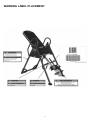
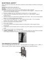
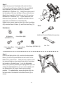
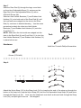
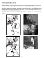
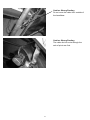
FAR INFRARED INVERSION TABLE
ITEM# 5214
OWNER’S MANUAL
The specifications of this product may vary from this photo and are subject to change without notice.
IRONMAN, IRONMAN TRIATHLON and M-DOT are registered trademarks of World Triathlon
Corporation.
This product is licensed by the IRONMAN TRIATHLON.
1
TABLE OF CONTENTS
Warranty----------------------------------------------------------------------------------------------3
Warning Label Placement----------------------------------------------------------------------- 4
Important Safety Precautions------------------------------------------------------------------- 5
Electrical Safety------------------------------------------------------------------------------------ 6
Included Hardware---------------------------------------------------------------------------------7
Tools--------------------------------------------------------------------------------------------------- 7
Overview Drawing--------------------------------------------------------------------------------- 8
Parts List----------------------------------------------------------------------------------------- ---- 9
Assembly Instructions-----------------------------------------------------------------------------11
Routing the Cable---------------------------------------------------------------------------------- 16
Safety Operating Instructions------------------------------------------------------------------- 18
Operation and Adjustments---------------------------------------------------------------------- 19
About Quick Release Ankle Lock System--------------------------------------------------- 22
Maintenance Instructions------------------------------------------------------------------------ 22
Storage----------------------------------------------------------------------------------------------- 23
About Temperature-------------------------------------------------------------------------------- 24
Remote Control and Controller Operation---------------------------------------------------25
Warm Up--------------------------------------------------------------------------------------------- 26
2
ONE YEAR LIMITED WARRANTY
Paradigm Health & Wellness, Inc. warrants to the original purchaser that this product is free from
defects in material and workmanship when used for the purpose intended, under the conditions that
it has been installed and operated in according to Paradigm’s Owner’s Manual.
Paradigm’s
obligation under this warranty is limited to replacing free of charge, any parts which may prove to be
defective under normal home use.
This warranty does not include any damage caused by improper
operation, misuse or commercial application.
to be free from defects for 1 (one) year.
From the date of purchase, the product is warranted
All parts and workmanship, including upholstery, foam, ball
bearings, pulleys, cables, shocks, all tension mechanisms, wheels, pedals and hardware are to be
free from defects for 90 days.
transferable.
This warranty is offered only to the original owner and is not
Proof of purchase is required.
This warranty is offered only to the original owner and
is not transferable.
Ordering Replacement Parts
Replacement parts can be ordered by calling or emailing our customer service department
1-866-924-1688
Monday through Friday, 8:00 AM - 5:00 PM (PST).
When ordering replacement parts please have the following information ready:
1. Owner’s Manual
2. Model Number
3. Description of Parts
4. Part Number
5. Date of Purchase
3
WARNING LABEL PLACEMENT
4
IMPORTANT SAFETY PRECAUTIONS
Read all instructions carefully before assembling operating this product. Retain this
owner’s manual and keep the original purchase receipt for future reference.
1. Consult your physician or other health care professionals before using the inversion table.
2. Always wear proper exercise apparel when using the equipment.
3. If any time you feel faint, light-headed or dizziness while operating the equipment, stop exercise
immediately. You should also stop exercising if you are experiencing pain or pressure.
4. Keep children and pets away from the equipment while in use.
5. Only one person should use the equipment at a time.
6. Make sure your equipment is correctly assembled before you use it. Be sure all screws, nuts,
and bolts are tightened prior to use.
7. Do not operate this or any exercise equipment if it is damaged.
8. Watch your body: come up slowly, dizziness after a session means you came up too fast. Wait a
while after eating before using the inversion table. If you get nauseous, come up as soon as you
feel queasy.
9. Always use this equipment on a clear and level surface. Do not use outdoors or near water.
10. Keep hands and feet away from any moving parts. Do not insert any object into any openings.
11. Keep loose clothes, jewelry away from moving parts.
12. WARNING: ALWAYS HOLD ON TO THE HANDLEBARS AND GO BACK SLOWLY WHEN
INVERTING. FAILURE TO COMPLY COULD RESULT IN SERIOUS BODILY INJURY.
13. Children under the age of 12 should not use the following fitness equipment.
14. If any part of the cable/wire is stripped or damaged, STOP using the far infrared foam bed
immediately.
15. Please always unplug the far infrared foam bed from the electrical outlet immediately after using
and before cleaning.
16. Do not operate the far infrared foam bed in a wet or moist environment and keep dry.
17. Do not allow water to directly contact any part of the far infrared foam bed.
18. For indoors household use only.
19. For any problems please contact customer service at the contact number in this manual.
DO NOT ATTEMPT TO SERVICE THE UNIT YOURSELF.
WARNING: Consult with your personal physician to see if inversion equipment is appropriate for you.
This is especially important for people with pre-existing health problems. Do not use this equipment
without your physician's approval.
Do not use this equipment if you have any of the following conditions or ailments:
.Extreme obesity
.Glaucoma, retinal detachment or conjunctivitis
.Pregnancy
.Spinal injury, Cerebral Sclerosis, or acutely swollen joints
.Middle ear infection
.High blood pressure, Hypertension, Recent stroke or Transient Ischemic attack
.Heart or circulatory disorders for which you are being treated
.Hiatus hernia or Ventral hernia
.Bone weaknesses including Osteoporosis, Unhealed fractures, Modularly pins, or Surgically
implanted orthopedic supports.
.Use of anti-coagulants including Aspirin in high doses.
Maximum Weight Capacity is 350 lbs/ 159 kgs.
5
ELECTRICAL SAFETY
When using the far infrared foam bed, basic precautions should always be followed, including the
following:
Read all instructions before using this unit.
DANGER - To reduce the risk of electric shock:
WARNING - To reduce the risk of burns, fire, electric shock, or injury to persons:
1. The far infrared foam bed should never be left unattended when plugged in. Unplug from outlet
when not in use and before cleaning.
2. Excessive heating may occur and cause fire, electric shock, or injury to persons.
3. Close supervision is necessary when this unit is used by, on, or near children, invalids or
disabled persons.
4. Use this unit only for its intended use as described in this manual. Do not use for other purpose
that is not recommended by the manufacturer.
5. STOP using this unit IMMEDIATELY if it has a damaged cord or plug. If it is not working
properly, been dropped, damaged, or dropped into water.
6. Keep the cord away from any heated surface.
7. Do not use it outdoors.
8. Do not operate where aerosol (spray) products are being used or where oxygen is being
administered.
9. To disconnect, turn the remote control or controller to the “OFF” position, then remove plug from
outlet.
10. Do not use on an infant or on a sleeping person.
11. CABLE STORAGE: When not in use, wrap the cable around the frame with the enclosed
Velcro strap as illustrated. Do not lay it on the ground to avoid cable damage.
THE DIMENSION OF HEATING PAD:
There is a heating pad inside the foam bed. The heating pad is 27.55” (length) x 11.81” ( width) , or
700mm (length) x 300mm (width) in dimension. The heating area is illustrated as below:
Heating Pad
700
100
300
6
INCLUDED HARDWARE
(13) Washer Ø20xØ8.5x1.5
8 PCS
(38) Hex Head Bolt M8x23
2 PCS
(54) Screw ST3.5x15
8 PCS
(15) Lock Nut M8
4 PCS
(27) Washer Ø16xØ6.5x1.0
2 PCS
(43) Hex Head Bolt M8x43
2 PCS
(51) Bolt M6x25
2 PCS
(55) Nut Cap Ø27xØ13.5
4 PCS
(68) Screw ST4.8x20
1 PC
(72) Pivot Arm Ring
2 PCS
TOOLS
Hex Tool
1 PC
Multi Hex Tool with Phillips Screwdriver
1 PC
7
36
8
43
13
29
12
55
8
38
27
13
12
37
74
49
27
76
21
50
13
2
15
74
72
16
78
48 54
10
47
13
15
13
55
33
19
15
13
34
16
27
51
53
46
13
52
1
5
32
20
19
28
4
27
51
53
30
25
54
24
7
31
75
64
61
62
3
9
41
18
5
67
23
70 69
26
14
35
68
44
71
22R
70
62
45
16
39
15
67
22L
61
62
62
41
17
63
42
66
65
15
56
40R
57
58
60
73
59
77
16
6
40L
62
11
31
62
17
7
25
OVERVIEW DRAWING
PARTS LIST
Part#
Description
001 Front Frame
Quan. Part#
Description
1 035 Foam Bed
Quan.
1
002
Rear U-Frame
1
036
Far Infrared Foam Grip
2
003
Adjustable Boom
1
037
Protective Cover
2
004
Bed Frame
1
038
Hex Head Bolt M8x23
2
005
Pivot Arm
2
039
Front Plastic Cover
1
006
Adjustable Lock Plate
1
040L Left Plastic Cover
1
007
Heel Holder Bracket
4
040R Right Plastic Cover
1
008
Folding Arm
2
041
Adjustable Boom Square End
Cap
2
009
Rear Rod
1
042
Locking Pin
1
010
Bolt M8x23
2
043
Hex Head Bolt M8x43
2
011
Front Rod
1
044
Height Scale
1
012
Phillips Screw M6x35
4
045
Latch
1
013
Washer Ø20xØ8.5x1.5
16 046
Hex Head Bolt M8x40
4
014
Round Plate
1
047
Left Rear Foot Cap with Handle
1
015
Lock Nut M8
12 048
Left Front Foot Cap with Handle
1
016
Lock Nut M6
6
049
Right Rear Foot Cap with Handle
1
017
Blocking Bush Ø28.5xØ23x14
2
050
Right Front Foot Cap with Handle
1
018
Spring Knob
1
051
Bolt M6x25
2
019
Safety Hook
2
052
Bed Frame End Cap
(□25x50mm)
4
020
Rubber Pad
1
053
Front Foot Cap
2
021
Rear U-Frame Oval End Cap
2
054
Screw ST3.5x15
10
022L Left Adjustable Boom Plate
1
055
Nut Cap Ø27xØ13.5
4
022R Right Adjustable Boom Plate
1
056
Adjustable Handle
1
023
In-Step Frame
2
057
Handle Cap
1
024
In-Step Foot Pad
2
058
Handle Spring
1
025
Round End Cap
4
059
Button
1
026
Lower Bed Frame Bushing
Handle Tip
1
027
Washer Ø16xØ6.5x1.0
6
061
Blocking Bush Ø28.5xØ22.5x10
2
028
Upper Bed Frame Bushing
1
062
Screw M3x10
10
029
Handlebar
2
063
Bolt M6x15
1
030
Knob
1
064
Carriage Bolt M8x70
2
031
Rubber Heel Holder
4
065
Bolt M6x30
1
032
Nylon Strap
1
066
Spacer Ø22x16.8
2
033
Loop Strap
1
067
Screw ST4.2x12
8
034
Strap Lock
1
068
Screw ST4.8x20
1
1set 060
9
PARTS LIST
Part#
Description
069 Shaft Nut Ø8
Quan. Part#
Description
1 074 Wire Plug
Quan.
2
070
Bolt M5x10
2
075
Controller
1
071
Bolt M8x50
4
076
Power Cord
1
072
Pivot Arm Ring
2
077
Remote Control
1
073
Bolt M4x25
1
078
Velcro Strap
2
10
ASSEMBLY INSTRUCTIONS
Step 1
Stand up the base of the machine by separating the frames.
Pull the Front and Rear U-Frames (1, 2) as far apart from
each others as possible. Then push down on the middle of
the two Folding Arms (8) until they are fully locked down.
Attach both Front Foot Caps (53) onto the Front Frame (1)
with two Ø16xØ6.5x1.0 Washers (27) and M6x25 Bolts (51).
Attach Left Rear/Front Foot Caps with Handle (47, 48) and
Right Rear/Front Foot Caps with Handle (49, 50) onto the
bottom of the Rear U-Frame (2) with eight ST3.5x15 Screws
(54). Tighten bolts and screws with the Multi Hex Tool with
Phillips Screwdriver provided.
8
2
1
49
47
54
Hardware:
50
53
27
51
48
54
53
51
27
Tool:
2 Washers
(Ø16xØ6.5x1.0)
2 Bolts (M6x25)
Multi Hex Tool with Phillips Screwdriver
8 Screws (ST3.5x15)
․․․․․․․․․․․․․․․․․․․․․․․․․․․․․․․․․․․․․․․․․․․․․․․․․․․․
Step 2
Install two Ø27xØ13.5 Nut Caps (55) onto M8x23 Hex Head Bolts (38).
Slide the Protective Covers (37) on to each side of the base as shown, and 37
pull down on the covers until the bottom of the covers are slightly lower than
the Folding Arms (8). Use the Velcro straps on the bottom of the covers
55
to secure the covers to the folding arms. When the covers are
assembled correctly, the folding arms should be fully covered by the
2
protective covers.
Hardware:
2 Nut Caps (Ø27xØ13.5)
11
55
38
1
Step 3
Slide the bottom of the Pivot Arms (5) into the brackets,
located at each side of the Bed Frame (4), align to the
desired hole on the arm with the peg on the bracket. Insert
the peg into the hole to lock the pivot arm in place. It is
recommended that you use the bottom hole on the pivot arm
until you become more familiar with the equipment.
5
4
5
5
4
․․․․․․․․․․․․․․․․․․․․․․․․․․․․․․․․․․․․․․․․․․․․․․․․․․․․
Step 4
Install the Pivot Arm Rings (72) onto the Pivot Arms (5).
Mount the Bed Frame (4) to the Rear U-Frame (2) by
inserting the ends of the Pivot Arms (5) into the channels
on the plates. The slotted portion of the rollers on the
end of the Pivot Arms (5) should be inserted into the
channels on the plates.
A
B
72
5
5
72
2
Hardware:
5
2 Pivot Arm Rings
12
72
Step 5
Attach the top end of Handlebar (29) onto the Rear
U-Frame (2) and Pivot Arm Ring (72) with one M8x23
Hex Head Bolt (38), M8 Lock Nut (15), and two
Ø20xØ8.5x1.5 Washers (13). Attach the bottom end of
the Handlebar (29) onto the Rear U-Frame (2) with one
M8x43 Hex Head Bolt (43), M8 Lock Nut (15), and two
Ø20xØ8.5x1.5 Washers (13). Tighten bolts with two
Multi Hex Tools provided. Install two Ø27xØ13.5 Nut
Caps (55) onto M8x23 Hex Head Bolt (38).
Repeat above same steps to attach the other Handlebar
(29) onto the Rear U-Frame (2) and Pivot Arm Ring (72).
15
13
72
29
43
13
38
55
13
13
15
2
Tool:
Hardware:
Multi Hex Tool with Phillips Screwdriver
8 Washers
(Ø20xØ8.5x1.5)
4 Lock Nuts (M8)
Hex Tool
2 Hex Head Bolts
(M8x23)
2 Hex Head Bolts 2 Nut Caps (Ø27xØ13.5)
(M8x43)
․․․․․․․․․․․․․․․․․․․․․․․․․․․․․․․․․․․․․․․․․․․․․․․․․․․․
Step 6
Pull out the Spring Knob (18), and slide the Adjustable
Boom (3) into the square bracket on the bottom of the
Bed Frame (4) as shown. Slide the boom upward, until
the desired height on the Height Scale (44) is just below
the bracket on the bed frame. Lock the Adjustable
Boom (3) in place by releasing the Spring Knob (18) and
sliding the Adjustable Boom (3) up or down slightly until
the Spring Knob (18) "pops" down into the locked
position. For added safety, secure the Knob (30) into
the back side of the bracket on the Bed Frame (4) as
shown.
13
4
30
18
3
44
Step 7
Slide the Rear Rod (9) through the large round hole
on the side of Adjustable Boom (3), and secure the
Rear Rod (9) on the Adjustable Boom (3) with a
ST4.8x20 Screw (68).
Slide two Heel Holder Brackets (7) and Rubber Heel
Holders (31) onto both ends of the Rear Rod (9) until
the lock teeth are wedged into the slots in the Rear
Rod (9), as shown in detailed drawing. Use the same
procedure to attach the other two Heel Holder
Brackets (7) and Rubber Heel Holders (31) onto the
Front Rod (11).
NOTE: Make sure the lock teeth are wedged into the
slots in the Rear Rod (9) and Front Rod (11) to lock the
Heel Holder Brackets (7) and Rubber Heel Holders (31)
in place before use.
Hardware:
7
3
7
31
11
68
31
31
31
9
7
7
Tool:
Multi Hex Tool with Phillips Screwdriver
1 Screw (ST4.8x20)
․․․․․․․․․․․․․․․․․․․․․․․․․․․․․․․․․․․․․․․․․․․․․․․․․․․․
Step 8
19
19
33
34
32
33
34
32
19
19
Attach the Nylon Strap (32) to the Strap Lock (34) by inserting the end of the strap up through the
bottom of the strap lock, loop the Nylon Strap (32) over the Pre-assembled Loop Strap (33) and down
through the Strap Lock (34). Now, loop the strap back over itself, and insert back through the Strap
Lock (34), and pull tight to secure. See diagram.
14
Step 9
Attach the Nylon and Loop Straps (32, 33) to the
inversion table by hooking the end of the Loop Strap (33)
to the pre-assembled loop on the back of the Bed Frame
(4) as shown. Now hook the other end of Nylon Strap
(32) to the other pre-assembled loop on the
Front U-Frame (1) as shown.
4
19
33
34
32 19
1
15
ROUTING THE CABLE
Route the cable as illustrated, place the Power Cord (76) from the Rear U Frame (2) onto the Pivot
Arm (5). Use a Velcro Strap (78) to secure the Power Cord (76) to the Pivot Arm (5). Slowly turn
the table all the way until it becomes 180 degree, to make sure the cable is long enough and will not
entangle any part of inversion table while you are using it. Finally, connect the Power Cord (76) to
the cable that comes from the Controller (75).
Caution: Do not route the cable other than instructed herewith, or the cable may be snapped during
inverting.
Power Cord
74
76
78
78
76
Rear
U-Frame
74
76
Pivot Arm
75
Power Cord
Pivot Arm
2
78
Velcro Strap
76
74
76
Cable from the
Controller
76
74
76
75
Power Cord
2
78
76
16
Caution: Wrong Routing
Do not route the cable from outside of
the handlebar.
Caution: Wrong Routing
The cable did not route through the
axle of pivot arm first.
17
SAFETY OPERATING INSTRUCTIONS
Incorrect
Correct
Pivot arm is NOT aligned correctly.
The pivot arm is not inserted all the
way into the curved slot.
Make sure the pivot arm is inserted
all the way into the slot. Pivot arm
is aligned correctly when the groove
sits directly on the curved slot and
the pivot arm is able to rotate freely.
WARNING: Please make sure both pivot arms are in the same hole to
prevent serious injury from occurring.
18
OPERATION AND ADJUSTMENTS
SHORTEN
LENGTHEN
THE STRAP
For added safety, a nylon strap has been included to restrict the degree of inversion. This strap can
be adjusted to different lengths to allow for a greater or lesser degree of inversion. To lengthen the
Nylon Strap (32) feed the top end of Nylon Strap (32) into the strap lock, and pull on the lower end of
the strap. To shorten the length feed the bottom end of Nylon Strap (32) into the strap lock, and pull
on the top end.
30
4
3
18
ADJUSTING THE BOOM
The Adjustable Boom (3) can be moved to a variety of different positions, in order to accommodate
the height of the person on the inversion table. To adjust the Adjustable Boom (3) loosen the knob
(30), pull out the Spring Knob (18), and slide the Adjustable Boom (3) up or down until the
desired height on the height scale is positioned just below the square bushing. When the
Adjustable Boom (3) is in the desired position, simply release the Spring Knob (18), slide the
Adjustable Boom (3) slightly up or down until the Spring Knob (18) locks into place, and tighten the
Knob (30).
19
5
4
PIVOT ARMS
The Pivot Arms (5) can be adjusted to allow for a greater or lesser degree of inversion. To adjust
the Pivot Arms (5) simply pull out on them until the post is out of the hole, slide them up or down to
the desired hole, push in until the post goes through the desired hole. The bottom hole provides the
least amount of inversion, while the top hole provides the greatest amount. It is recommended that
beginners use the bottom hole until they are familiar with the inversion table.
NOTE: Both Pivot Arms (5) must be adjusted to the same hole. Trying to adjust the Pivot Arms (5)
on two different positions could cause damage to the inversion table or injury to the user.
THE HANDLEBARS
For added convenience and safety, a set of Handlebars (29) has been added to the inversion table.
These Handlebars (29) are located at the top of the Rear U-Frame (2). The Handlebars (29) are
there to help you return to the upright position from any degree of inversion. If you wish to return to
the upright position, and the bed is moving too slowly, or not moving at all, simply grab the
Handlebars (29) and pull on them until you return to the upright position.
NOTE: The inversion table should always return to the upright position when you move your hands
below your waist. If it does not, the inversion table is probably not adjusted correctly to your height.
* Always hold on to the handlebars and go back slowly.
physical injury.
20
Failure to comply could result in serious
1.
2.
3.
4.
5.
6.
GENERAL PRECAUTIONS
Make sure that the Pivot Arms (5) are locks on the lowest hole for the first few attempts.
It is recommended that someone be with you while you are using this inversion table for the first
few times.
Make sure that the Rubber Heel Holders (31) are holding your feet securely.
Make sure that the Adjustable Boom (3) is properly set to your height.
Make sure that the Adjustable Boom (3) is held securely by both the Spring Knob (18) and the
Knob (30).
Make sure that there is enough room for the bed to rotate completely.
BALANCING THE INVERSION TABLE
The inversion table is like a very sensitively balanced fulcrum. It responds to very slight changes in
weight distribution. So, it is very important to make sure that the height is adjusted properly. To do
this, mount the inversion table, lock your ankles into the heel holders, and lie back with your hands at
your sides. Slowly place you hands across you chest. While in this position, your head should still
be above our feet. If your feet are above your head, dismount and adjust the height again.
1.
2.
3.
4.
5.
6.
USING THE INVERSION TABLE
Start by lying fully back on the bed with your hands at your side, or resting on your thighs.
Keeping your hands close to your body begin to raise your arms slowly allowing the table to
rotate backward. Stop, or lower your arms to control the downward rotation of the table.
Raise your arms until they are over your head. At this point, the inversion table will be as far
back as it can go.
As you get more comfortable with the use, rock the bed slowly by moving your arms up and
down slowly.
It is recommended that the inversion table be used for five or ten minutes each morning, and
again each evening.
Return to the upright position by slowly moving your hands back down to your thighs.
21
1.
2.
3.
4.
5.
SUGGESTIONS FOR USE
Begin slowly: invert only 15~20 degrees to begin with. Stay inverted only as long as you are
comfortable. Return upright slowly.
Make gradual changes: increase the angle only if it is comfortable. Increase angle only a few
degrees at a time. Increase the time of use 1~2 minutes up to ten over a period of weeks.
Add stretching and light exercise only after you are comfortable with inversion.
Watch your body: come up slowly, dizziness after a session means you came up to fast. Wait a
while after eating before using table. If you get nauseous, do not fight it, come up as soon as
you feel queasy.
Keep moving: movement while inverted encourages blood, circulation. Movement may be
accomplished by either rhythmic traction or light exercise. Do not exercise strenuously while
inverted, limit partial inversion without movement to one or two minutes. Limit full inversion
with no movement to only a few seconds.
Invert regularly: we recommend two or three times a day depending upon your current condition.
Try to schedule it for the same time each day.
ABOUT QUICK RELEASE ANKLE LOCK SYSTEM
Before mounting the table, press the button on top and pull open.
Pull the handle to lock your feet
securely after mounting the table.
When dismounting the table, press the button to release and open.
If the button is too tight, pull the
handle toward you first before pressing the button to release.
Warning: To avoid serious injury, feet must be secured before
inverting. Do not use the table if the ankle lock system does
not function properly.
MAINTENANCE INSTRUCTIONS
You should check your inversion table for any kind of wear and tear before each use.
1.
2.
3.
Check the pivot arms, bed, heel holders for wear and tear.
Replace damaged and worn components immediately.
Keep all damaged equipment out of use until it is repaired.
22
STORAGE
FOLDING THE INVERSION TABLE
For your storage convenience, the inversion table can be folded down to place against a wall, under
a bed, or in a storage area. To fold the inversion table pull out the Spring Knob (18) and loosen
Knob (30). Now, slide the Adjustable Boom (3) all the way up into the frame, until the instep frame
is just below the Bed Frame (4), release the Spring Knob (18) and slide the Adjustable Boom (3)
slightly up or down until the Spring Knob (18) locks the Adjustable Boom (3) in place. Remove the
Bed Frame (4) from the base by lifting up on the Bed Frame (4) until the Pivot Arms (5) come out of
the arm slots located at the top of the Rear U-Frame (2), (Make sure the Strap is not attached to the
Bed Frame before attempting to remove it.) Push up on the center of the Folding Arms (8) and push
the Front and Rear U-Frames (1, 2) together until they meet. Now the machine is ready to be
stored, allowing you to unfold it quickly and easily whenever you want to use it.
23
ABOUT TEMPERATURE
1.
2.
3.
The temperature readout is based on the sensor built-in with the Fiber Glass Infrared heater mat
inside. It does not represent the temperature of the cushion surface.
Put a towel or cloth on top of the cushion will help increase the temperature even faster.
After the 15-20 minutes preheat time, get on the inversion table and lay your back on the heat
cushion, the temperature will continue to increase.
24
REMOTE CONTROL AND CONTROLLER OPERATION
1.
2.
3.
4.
5.
6.
By default setting, when turned on, the temperature is set to 140 degrees F (60 degrees C), and
timer is set to 40 minutes. This will ensure the far infrared foam bed heats up as quickly as
possible.
Adjust the temperature down to your desire setting after preheat. Set Low Heat at
100-110, Medium Heat at 120-130, or High Heat at 130-140 degrees F.
The normal preheat time is 15-20 minutes, under room temperature at 68-77degrees F
(20-25 degrees C).
Both Remote Control and Controller can be used to set desired temperature and time.
The LED on the Controller reads out the current temperature and remaining time.
The Remote Control will function either aiming directly to the Controller or to the wall/ceiling in
the room when using the table.
The Remote Control comes with a Velcro strap. Pull apart to open the Velcro strap for two
layers. Remove the liner away from the short layer, choose adhesive backing for bonding to
the back of the Remote Control. Remove the liner away from the long layer, choose adhesive
backing for bonding to the inversion table where it is easy reach by hand, such as
Front U-Frame. Attach the Remote Control to it when not in use. Or simply drop it into the
mesh pocket of the right side cover for storage.
Precautions
Plug must be plugged into an appropriate outlet that is properly installed. Improper connection can
result in the risk of electric hazard.
A typical indoor extension cord may used to reach a desired electrical outlet.
Set the temperature and time to a comfortable level.
Far Infrared Foam Bed Operation
Plug the unit into the outlet with the “POWER” light off before starting it and use the ON/OFF switch to
turn on the cushion. After starting the unit, the digital light of temperature displays the set
temperature as 140 degrees F (60 degrees C). The temperature can be changed by pressing the
“∧” or “∨” button to increase or decrease the temperature. The digital light of time displays the set
time is 59 minutes. Timer can be changed by pressing the “+” or “-” button to increase or decrease
time. After 5 seconds, the digital light in temperature flashes 2 times and then returns to display the
current temperature of far infrared foam bed. When pressing the button “∧” or “∨” again, it will
change to display the “set temperature” and can be set to desired temperature.
Press the ℃/℉ button to switch the display between Centigrade and Fahrenheit.
Buzzer will beep when time counts down to 0 or the temperature reaches your set temperature.
After using the unit, turn off the ON/OFF switch, and unplug the power cable.
CONTROLLER PANEL
REMOTE CONTROL
25
WARM UP
The WARM-UP is an important part of any workout. It should begin every session to prepare your
body for more strenuous exercise by heating up and stretching your muscles, increasing your
circulation and pulse rate, and delivering more oxygen to your muscles.
HEAD ROLLS
Rotate your head to the right for one count,
feeling the stretch up the left side of your neck, then rotate your head back
for one count, stretching your chin to the ceiling and letting your mouth
open. Rotate your head to the left for one count, then drop your head to
your chest for one count.
SHOULDER LIFTS
Lift your right shoulder toward your ear for one count. Then lift your left
shoulder up for one count as you lower your right shoulder.
SIDE STRETCHES
Open your arms to the side and lift them until they are over your head.
Reach your right arm as far toward the ceiling as you can for one count.
Repeat this action with your left arm.
QUADRICEPS STRETCH
With one hand against a wall for balance, reach behind you and pull your
right foot up. Bring your heel as close to your buttocks as possible. Hold
for 15 counts and repeat with left foot.
26
INNER THIGH STRETCH
Sit with the soles of your feet together and your knees pointing
outward. Pull your feet as close to your groin as possible. Gently
push your knees toward the floor. Hold for 15 counts.
TOE TOUCHES
Slowly bend forward from your waist, letting your back and shoulders
relax as you stretch toward your toes. Reach as far as you can and
hold for 15 counts.
HAMSTRING STRETCHES
Extend your right leg. Rest the sole of your left foot against
your right inner thigh. Stretch toward your toe as far as
possible. Hold for 15 counts. Relax and then repeat with left
leg.
CALF/ACHILLES STRETCH
Lean against a wall with your left leg in front of the right and your
arms forward. Keep your right leg straight and the left foot on the
floor; then bend the left leg and lean forward by moving your hips
toward the wall. Hold, then repeat on the other side for 15
counts.
27
www.ActiveForever.com | [email protected]
p: 1-800-377-8033 | f: 602-296-0297