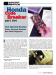
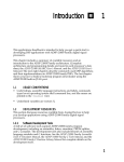
1
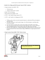
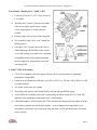
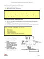
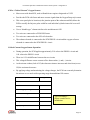
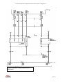
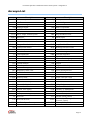
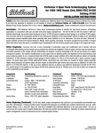
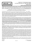
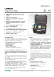
Learning Guide POWERTRAIN SPECIALIST HONDA POWERTRAIN CONTROL SYSTEMS – DIAGNOSTICS 2 COURSE NUMBER: PT240-02 Powertrain Specialist: Honda Powertrain Control Systems – Diagnostics 2 Notice Due to the wide range of vehicles makes and models, the information given during the class will be general in nature and should not be taken as specific to any vehicle/unit. Please consult manufacturer specifications for the correct number/specifications and repair procedures for the vehicle you are testing. This document is meant to be used as a guideline only. For further information, please contact toll-free: 1-855-813-2101 or email [email protected] No part of this book may be reproduced, stored in any retrieval system or transmitted in any form or by any means (including but not limited to electronic, mechanical, photocopying and recording) without prior written permission of CARS Training Network Inc. This applies to all text, illustrations, tables and charts. Copyright © 2014 CARS Training Network Inc Page ii Powertrain Specialist: Honda Powertrain Control Systems – Diagnostics 2 Introduction OBJECTIVES Upon successful completion of this segment the participant will be able to: Provide expanded information and diagnostics concerning: – Variable Valve Timing with Electronic Lift Control: – SOHC/DOHC VTEC – SOHC VTEC-E (Economy) P1259 – HO2S Circuit & Rich/Lean P0130-P0175 – Air/Fuel Ratio Sensor P1149-P1167 Page 1 Powertrain Specialist: Honda Powertrain Control Systems – Diagnostics 2 Honda Powertrain Control Systems Honda Powertrain Control Systems Module 2 Understanding Honda’s unique engine management systems will help keep diagnostic time to a minimum. In the recent past and present, conventional Honda vehicle engines have included a variety of VTEC in-line 4 cylinder and V6 cylinder designs. The J30 V6 engine features a 3 rocker arm VTEC system, 10:1 compression ratio and a novel exhaust manifold cast as one piece with the cylinder head. Wards Automotive placed this engine on its “10 Best” engine list for 2003 and 2004. A J35A91 V6 engine is used in Honda Ridgeline trucks. Variable Cylinder Management (VCM) has been added to the J35 engine featured in 2005 Odyssey and 2006 Pilot vehicles. The Honda J35 V6 is also currently used by General Motors as the optional engine in their Saturn VUE. Service Information for Honda engines is often categorized within a service manual by engine number. Engines may look alike but different engine numbers could have different specifications. The following chart gives some examples of engine numbers and their applications: Sample Honda Engine Numbers Year 1996-99 Civic Accord D16Y7-1.6L SOHC 4 C27A4-2.7L SOHC V6 D16Y8-1.6L SOHC VTEC F22B1-SOHC VTEC 4 D16Y5-1.6L SOHC-E F22B2-2.2L SOHC 4 1999-02 CR-V Odyssey F23A1-2.3L SOHC VTEC 4 F23A4-2.3L SOHC VTEC 4 F23A5-2.3L SOHC 4 2000 B16A2-1.6L DOHC VTEC 4 J35A1-3.5L SOHC VTEC V6 D16Y7-1.6L SOHC VTEC 4 D18Y8-1.6L SOHC VTEC 4 2001 B20Z2-2.0L DOHC 4 2002 2003 2005/06 J35A4-3.5L SOHC VTEC V6 LDA-MF3-1.3L SOHC 4 K24A1-2.4L DOHC i-VTEC 4 Page 2 Powertrain Specialist: Honda Powertrain Control Systems – Diagnostics 2 Variable Valve Timing and Lift Electronic Control (VTEC) Variations 1. Single Overhead Cam (SOHC) VTEC • 3 Rocker System • 3 Rocker “Resting Valve” System 2. SOHC VTEC-E (Economy) 3. Dual Overhead Cam (DOHC) VTEC 4. i-VTEC - with Variable Timing Control (VTC) 5. i-VTEC - with Variable Cyl. Management (VCM) VTEC is a valve rocker arm control system that improves combustion efficiency throughout a wide RPM range The intake rocker arm’s control system changes valve lift and timing by controlling intake rocker arm actuation Activation depends on engine speed, vehicle speed, engine load and other sensor inputs The system gets good torque and consumption when operating in the low engine speed range, while maintaining high power output when operating in the high engine speed range Most non-VTEC engines have a camshaft design that compromises ideal valve lift and duration for best performance in the relatively narrow range of RPM where an engine operates most of the time. 1. Single Overhead Cam (SOHC) VTEC 3 Rocker System SOHC engines only have the VTEC mechanism operating on the intake valves Page 3 Powertrain Specialist: Honda Powertrain Control Systems – Diagnostics 2 Three Rocker “Resting Valve” SOHC VTEC Used in 1999 Acura 3.2 L TL, 2001 Accord 2.3 L 4 cylinder “Resting valve” because it operates one intake valve at low engine speeds and two intake valves at high speeds, 5 rocker arms per cylinder Primary intake valve operates with normal lift The secondary intake valve “rests” during low RPM operation Like other VTEC systems, above the 2300 to 3200 RPM range, the PCM directs the system over to full opening, two intake valve operation, locking three rocker arms together and using the more aggressive mid-position rocker arm cam lobe profile 2. SOHC VTEC-E (Economy) VTEC-E was adopted to increase engine efficiency at low speeds instead of optimizing performance at high RPM Found on several Honda fuel efficient cars (1992 to 1995 Civic VX and 1996 to 2000 Civic HX 4 cylinder models) Two intake rocker arms per cylinder. The primary arm operates on a normal profile cam lobe during all RPM ranges At low RPM, the secondary rocker arm is operated by an almost round (0.65 in./1.6cm lift) cam lobe which opens the second intake valve a small amount 2500 RPM (approx): PCM energizes the VTEC solenoid, directing pressurized engine oil to the rocker arms to pin the two rocker arms together—system changes from single intake valve operation to a dual intake valve operation, using the same cam lift and duration the valves had at lower speeds. Page 4 Powertrain Specialist: Honda Powertrain Control Systems – Diagnostics 2 3. Dual Overhead Cam (DOHC) VTEC 3.0 L DOHC V6 engines are used on high performance vehicles such as the Acura NSX and Honda S2000. Three rocker VTEC is adapted to both the intake and exhaust valves for increased performance at high RPM. This configuration has the potential to produce 100 horse-power per litre of displacement. In a fashion similar to SOHC VTEC versions, switching of the rocker arms/cam lobes is controlled by a PCM operated solenoid. As engine RPM increases, a locking pin is pushed by oil pressure to connect the primary rocker arms to the high RPM mid-rocker arm cam followers for operation based on the center higher lift, more aggressive cam lobe profile. 4. i-VTEC - with Variable Timing Control (VTC) and i-VTEC - with Variable Cyl. Management (VCM) VTEC System Oil Flow 1 – VTEC Oil Control Solenoid 2 – Spool Valve 3 –Oil supply to engine 4 – Right Intake Rocker Arm Assemblies 5 – Oil return passages 6 – Left Intake Rocker Arm Assemblies 7 – Oil supply to rocker arms 8 – Oil return passage 9 – Oil supply from sump 10 – Oil Filter 11 – Oil pressure switch Page 5 Powertrain Specialist: Honda Powertrain Control Systems – Diagnostics 2 Honda i-VTEC Engines with Variable Cylinder Management (VCM) In 2004, Honda introduced an i-VTEC V6 engine (J-series) on U.S. Odysseys. On this engine, i-VTEC does not feature cam phasing but rather adds cylinder deactivation technology known as Variable Cylinder Management (VCM) During light load and reasonable speed conditions, a PCM controlled solenoid unlocks the cam followers on the rear cylinder bank from their respective rockers. The rear cam followers then float freely while the valve springs hold the rear valves closed. The engines drive-by wire throttle, vibration and noise reduction technology assists in smoothing out the power delivery, making this systems operation almost imperceptible. Rear Mount Chamber A Rotor Valve Chamber B Diaphragm Actuator Controlled Engine Mount - Style # 1 (Pre-2004) Honda used PCM controlled, liquid filled, rear engine mounts on some pre-2004 Accords and Odysseys with i-VTEC engines. The purpose of a controlled mount is to reduce engine vibration in the idle rpm range, without affecting vibration damping at higher speeds. Major Components: PCM • A control solenoid valve • Rotary valve • Rear engine mounts with a built-in diaphragm actuator • Vacuum source Page 6 Powertrain Specialist: Honda Powertrain Control Systems – Diagnostics 2 Controlled (Active) Engine Mount - Style # 2 (Post 2004 i-VTEC V/6 with VCM) Some 2004 and later Honda 4 cylinder and V6 i-VTEC VCM engines with Variable Cylinder Management (VCM) use engine mounts which function at idle and low torque conditions V6 operation in the 3 cylinder mode (combustion every 240 degrees) results in better fuel economy and emissions but creates noise and vibrations “Active Control” engine mounts and “Active Noise Control” systems to counteract these effects PCM uses crankshaft and camshaft position sensors’ input to estimate engine vibration in 3 cylinder mode PCM provides ground (as needed) to energize and de-energize the engine mount control solenoids in each active mount Active Control Mount # 2 Circuit The plunger assembly is pulled downward when energized, causing the top of the fluid filled mount to drop down and the engine to move down with the mount A spring pushes the plunger assembly, upper mount and engine upward when the solenoids are de-energized Based on the frequency determined by the PCM, the engine mount will push and pull on the engine, physically counteracting the vibration motion. Notes: _______________________________________________________________________ _______________________________________________________________________ _______________________________________________________________________ Page 7 Powertrain Specialist: Honda Powertrain Control Systems – Diagnostics 2 Oxygen Sensors and Air Fuel Ratio Sensors Stoichiometric (Zirconia) Oxygen Sensor (O2S) Lean Air/Fuel Sensor (LAF) o 5-Wire “Oxygen Pump” Sensor o 4-Wire “Critical Current” Sensor Stoichiometric (Zirconia) Oxygen Sensor (O2S) Important to isolate cause of O2 sensor DTCs, not just replace sensor: Fixed O2 Sensor Signal diagnosis Fixed high voltage signals (indicate the mixture is rich) possible causes may include: Dripping injector High fuel system pressure Defective coolant sensor (always signals a cold engine) Fixed low voltage signals (indicate the mixture is lean) possible causes may include: Clogged injectors Low fuel pressure A vacuum leak MAF or MAP out of calibration (indicates less than actual airflow) Uneven or Partial O2 Sensor Switching (slow or intermittent switching) possible causes may include: Sluggish O2 sensor (rise time too slow – more than 100 ms @ 2500 rpm) Restricted MAP hose Vacuum leak Converter notes: Excessive heat may result from either misfire and/or excessively rich air/fuel ratios. Normal converter operating temperatures are typically between 400C and 600C (752F and 1,112F). Internal damage may occur around 800C (1472F). Page 8 Powertrain Specialist: Honda Powertrain Control Systems – Diagnostics 2 Lean Air Fuel (LAF) Oxygen Sensors (LAF) sensors: 5 Wire “Oxygen Pump” Sensor 4 Wire “Critical Current” Sensor (newer) A conventional zirconia O2 sensor operates within a very narrow A/F ratio band (14.2 to 15.2) Newer Honda vehicles (with lean burn capability) can operate as lean as 23:1— Stoichiometric sensor signals cannot be used with “lean burn” since the oxygen content in the exhaust is higher than the stoiciometric O2 sensor is capable of measuring. Lean burn type engines therefore require “wide band” LAF sensors to function under these conditions. “Oxygen Pump” Type Lean Air/Fuel (LAF) Sensor The 5-wire LAF sensor is essentially made up of two zirconia elements (cells) that share a diffusion chamber. The diffusion chamber allows O2 to move between the two cells. The oxygen pump style sensor uses plate type elements instead of thimble style construction. The five wires on the “oxygen pump” LAF sensor are: Heater positive Heater negative Sensor element positive Control element positive Common ground for sensor and control elements Notes: Common ground for the two elements goes to the PCM and is not the same as chassis ground. It is only the PCM’s ground reference—you will read a small voltage when measuring between the PCM ground and chassis ground. Honda scan tool software displays O2S data in +/- ma instead of volts like the conventional O2 sensor. Wide Band O2 Sensor Page 9 Powertrain Specialist: Honda Powertrain Control Systems – Diagnostics 2 4 Wire “Critical Current” Oxygen Sensors Most recent wide-band O2S, used on Honda/Acura engines designated as ULEV Provides the PCM with faster and more accurate signals than the Oxygen Pump style sensor This extra speed plus its location (at the junction point of the exhaust manifold) allows the PCM to modify fuel injector pulse width for each individual cylinder instead of an overall average Uses a “thimble type” element similar to the stoichiometric O2S. Two wires are connected to a PWM O2S heater Two wires are connected to the O2S cell electrodes The exhaust electrode is connected to the PCM PHO2S- circuit and the oxygen reference electrode is connected to the PCM PHO2S+ circuit Critical Current Oxygen Sensor Operation During operation, the PCM applies approximately 2.18 volts to the PHO2S+ circuit and 1.80 volts to the PHO2S- circuit There is a 0.38 volt difference between the two circuits This voltage difference causes current to flow between the (+) and (–) circuits As the mixture richens (lack of O2) the element resistance increases and when lean (excess O2) the resistance decreases. By applying voltage and monitoring the voltage changes, the PCM can accurately determine the mixture over a much wider operating range than traditional O2 sensors. HO2S Circuit Voltage KOEO, HO2S Disconnected Heater control 4.6-5.0v Heater Supply Voltage B+ Reference Voltage 2.6-3.1v Low reference 2.2-2.7v Pump current Less than 0.5v Input pump current Less than 0.5v Typical Readings— always consult service information Page 10 Powertrain Specialist: Honda Powertrain Control Systems – Diagnostics 2 Typical Schematics—always consult service information Page 11 Powertrain Specialist: Honda Powertrain Control Systems – Diagnostics 2 Acronym List Acronym Description Acronym AAI ACL A/C A/D A/F ANC Air Assist Injection Air Cleaner Air Conditioning Analog to Digital Air/Fuel Active Noise Cancellation Hg IAB IAC IAR IAT ICM Description Mercury Intake Air Bypass Idle Air Control Intake Air Resonator Intake Air Temperature Ignition Control Module ATTS Active Torque Transfer System IMA Integrated Motor Assist BARO Barometric BOB Break Out Box CARB Calif. Air Research Board KS Knock Sensor LAF Lean Air Fuel LEV Low Emission Vehicle CD-ROM Compact Disc-Read Only Memory CKP CL CLV CO CO2 COM CVT CYP DIC DIS DTC DLC EBD E-EGR ECM ECT EGR ELD EPA EVAP FIA FT Crank Position Sensor Closed Loop Calculated Load Value Carbon Monoxide Carbon Dioxide Communication Continuously Variable Trans Cylinder Position Driver Input Centre Distributorless Ign. System Diagnostic Trouble Code Data Link Connector Electronic Brake Distribution Electronic EGR Engine Control Module Engine Coolant Temperature Exhaust Gas Recirculation Electrical Load Detector Environ. Prot. Agency Evaporative Fuel Injection Air (System) Fuel Trim FTP Fuel Tank Pressure FTVR Fuel Tank Vapour Recovery HC Hydrocarbons LT FT Long Term Fuel Trim MAP M/T NOx OBD OL ORVR OSM O2S PGM-FI PID PSP PW ST FT TCC TCM TP TWC ULEV VCM VSS VSA VTC Manifold Absolute Pressure Manual Transmission Oxides of Nitrogen On-board Diagnostics Open Loop On-board Refueling Vapour Recovery Output State Monitor Oxygen Programmed Fuel Injection Parameter Identifier Power Steering Pressure Pulse Width Short Term Fuel Trim Torque Converter Clutch Transmission Control Module Throttle Position 3-Way Catalyst Ultra Low Emission Vehicle Variable Cyl. Management Vehicle Speed Sensor Vehicle Stability Assist Variable Timing Control Variable Valve Timing & Lift VTEC Electronic Control WU-TWC Warm-up 3 Way Catalyst Page 12