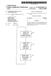
1
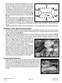
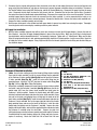
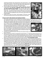
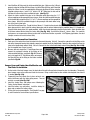
®
Performer X Open Track Turbocharging System
for 1992-1995 Honda Civic SOHC VTEC D16Z6
Catalog #1503
INSTALLATION INSTRUCTIONS
PLEASE study these instructions carefully before installing your Edelbrock Open Track Turbocharging System for Honda Civic D16Z6.
If you have any questions or problems, do not hesitate to contact our Technical Hotline at: 1-800-416-8628, from 7am-5pm
Monday-Friday, Pacific Standard Time or via e-mail at: [email protected]. Please complete and mail your warranty card.
Description: The Edelbrock Performer X Open Track Turbocharging System is intended for high boost pressure, off-highway
applications in conjunction with user provided and tuned engine management. The Part #1503 kit with the Garrett T-28R ballbearing turbocharger can provide boost pressures of up to 20 PSIG (Pressure reading at boost gauge) on a modified D16Z6 engine.
The kit comes with all of components needed for the mechanical installation of the turbocharger system including a pre-assembled
turbocharger-exhaust manifold-outlet elbow assembly with hoses installed; air to air intercooler; Tial blow-off valve; Performer X
intake manifold; and all of the required fasteners, fittings, hoses, gaskets, and piping. No engine management is provided. An engine
fitted with this kit using the stock un-modified engine management will not function properly and damage to the engine will occur.
Before Beginning: Someone who has a basic knowledge of automobile repair and modification and is familiar with and
comfortable with working on their vehicle can accomplish the mechanical installation of this kit using common tools and procedures.
Successful operation of the engine with this turbocharger kit requires a working knowledge of the set-up and tuning of an engine
management system. The required modifications to your engine and fuel delivery system are dependent on the boost pressure and
power output you desire to run. A properly tuned stock D16Z6 engine in good condition with a stock fuel delivery system can typically
withstand 7-8 PSIG (Pressure reading at boost gauge) of boost making 170-180 hp at the wheels with a stock maximum engine
speed. For boost levels above 8 PSIG, aftermarket pistons, connecting rods, and valves are required to assure engine durability.
Higher boost pressures and power output will also require an aftermarket high-volume fuel pump such as Edelbrock #17938 (190
liter/hr) or #17936 (255 liter/hr). If the use of four additional injectors is desired, use Edelbrock Secondary Fuel Rail kit P/N 4752.
The specifications for the Edelbrock test engine (D16Y8) that produced 283 hp at 7000rpm and 232 ft-lbs at 6200 rpm (measured
at the crankshaft) are as follows:
Component
Engine Block
Crankshaft
Connecting Rods
Pistons
Rings
Cylinder Head
Intake Valves
Specifications
T-sleeved by RS Machine, Carson CA
Stock
Crower: Billet - P/N B93745B
(D16Y8 application)
JE: P/N 149178
Je: P/N XC7500H
Stock with 3-angle valve job,
quench removed from combustion
chamber, no port work performed
Ferrea: P/N F1822 (stock diameter)
Component
Exhaust Valves
Valve Springs
Ti Retainers
Camshaft Lift/Duration
Camshaft Timing
Head Bolts
Fuel injectors
Map Sensor
Engine Management
Components Not Listed
Specifications
Ferrea: P/N F1821 (stock diameter)
Crower: P/N 68180
Crower: P/N 87096
Stock
Stock
ARP: Head Stud Kit P/N 208-4305
RC Engineering: P/N SL9-550
Hondata: 3-bar
Motec
Stock
Before Beginning (Continued): For this test, Motec engine management was used but is not necessarily recommended over
any other manufacturer. Customer tunable engine management packages are available from multiple manufacturers such as: AEM,
Hondata, Motec, F.A.S.T., Accel DFI, Apex, etc. and will be available from Edelbrock MotoTron in the near future (Note: This list, as
well as any list of parts used in engine testing does not imply any specific recommendations. Selection of engine components and
engine management should be determined by the customer/engine builder).
©2004 Edelbrock Corporation
Rev. 9/04
Page 1 of 9
Catalog #1503
Brochure #63-0258
Additional Tuning Notes: To prevent over-speeding, the turbocharger boost pressure should be limited to 20 psig, or crankshaft
horsepower should be limited to 280-300 horsepower. The recommended max boost is applicable at sea level. At higher altitudes,
the user should be careful not to over-speed the turbocharger, as more turbo speed is required to reach equivalent boost pressures.
REMEMBER: WHEN WORKING AROUND GASOLINE, DO NOT SMOKE, AND KEEP ALL OPEN FLAMES, SPARKS AND OTHER
SOURCES OF IGNITION AWAY FROM THE WORK AREA. Failure to do so can result in a FIRE or EXPLOSION.
After Installation, Before Starting the Vehicle:
We recommend the use of a synthetic 10W30 motor oil. Mobil1 was used in our testing. Before starting the vehicle, the turbocharger
oil drain hose should be disconnected from the oil pan and the engine should be turned over with the starter until oil is running out
of the oil drain hose (Note: This may take one or two minutes of intermittent cranking for the oil system to be primed and for oil to
reach the drain hose. To keep from abusing the starter, crank the engine in 15-20 second intervals, until oil reaches the drain hose).
This will ensure that the turbo is lubricated before the initial start-up. This should be done with the spark plugs removed and the
ignition system disabled. This will prevent any unnecessary load being placed on the starter.
Kit Contents
Qty.
Description
Individual Parts
❑1
❑1
❑1
❑1
❑1
❑1
❑1
❑1
❑1
❑1
❑1
❑1
❑1
Turbocharger / Exhaust Manifold / Exhaust Elbow / Oil-Water Line Assembly
Performer X Intake Manifold / Turbo Fuel System Assembly
Oil Supply Sandwich Adapter Assembly
Intercooler
Compressor Inlet Pipe, Cast Aluminum
Compressor Outlet Pipe, Cast Aluminum
Intercooler Inlet Pipe
Intercooler Outlet Pipe
Intake Manifold Inlet Pipe
Exhaust Down Pipe
Air Filter / Attachment Hose / Clamps Assembly
Blow Off Valve Assembly
Gasket, Intake Manifold
Hose Kit
❑1
❑1
❑1
❑1
❑4
❑ 3ft.
❑ 3ft.
❑ 3ft.
❑ 5ft.
❑ 7ft.
Turbo Oil Drain Hose Assembly
Turbo Fuel Rail to Stock Fuel Rail Hose Assembly
Fuel Filter to Turbo Fuel Rail Fuel Hose Assembly
2 ¼” Silicone Hose Coupling (Intercooler Outlet Pipe to Intake Manifold Inlet Pipe)
2 ¼” - 2 ½” Silicone Hose Couplings (Compressor/Intercooler Piping Connections)
3/8” Cam Cover Breather Hose
5/16” Purge / PCV Hose
¼” Fuel Hose, Fuel Pressure Regulator Return
5/32” I.D. Vacuum Hose,
¼” Red Silicone Hose, Wastegate & Blow-Off Valve
Hose Clamp Kit
❑4
❑6
❑2
Hose Clamps, 2 1/16” - 3”
Hose Clamps, 1 13/16” - 2 ¾”
Hose Clamps, 5/16” I.D.
©2004 Edelbrock Corporation
Rev. 9/04
Page 2 of 9
Catalog #1503
Brochure #63-0258
Kit Contents (Continuation)...
Hardware Kit
❑1
❑1
❑1
❑1
❑1
❑1
❑1
❑3
❑3
❑2
❑2
❑2
❑4
❑2
❑3
❑3
❑2
❑2
Throttle Cable Bracket
Idle Air Controller (IAC) Cover Plate (Auto Transmission Applications)
Support Brace (Compressor Inlet Pipe to Transaxle)
6mm x 1.0, 16mm Long Black Oxide, Serrated Flange Bolt (Intercooler Upper Mount)
6mm x 1.0, Black Oxide, Serrated Flange Nut (Intercooler Upper Mount)
1/4” Zinc Plated Washer (Intercooler Upper Mount)
6mm x 1.0, 12mm Long Hex Head Bolt (Support Brace to Compressor Inlet Pipe)
6mm x 1.0, 20mm Long Socket Head Capscrew (Compressor Outlet Pipe to Compressor Outlet Flange)
6mm Spring Washer (Compressor Outlet Pipe to Compressor Outlet Flange)
8mm x 1.25 Stud (Compressor Inlet Pipe to Compressor Inlet Flange)
8mm x 1.25 Lock Nut (Compressor Inlet Pipe to Compressor Inlet Flange)
5/16 SAE Washer (Compressor Inlet Pipe to Compressor Inlet Flange)
8mm x 1.25, 20mm Long Socket Head Cap Screw (Turbo Oil Drain Hose to Turbo Oil Drain Flange & IAC Cover)
8mm Spring Washer (Turbo Oil Drain Hose to Turbo Oil Drain Flange)
10mm x 1.5 Studs (Exhaust Downpipe to Turbo Outlet Elbow)
10mm x 1.5 Flange Nut (Exhaust Downpipe to Turbo Outlet Elbow)
¼-20 x ½” Hex Head Bolt (Turbo Oil Drain Adapter Fitting, Steel Oil Pan)
¼-20 x 5/8” Hex Head Bolt (Turbo Oil Drain Adapter Fitting, Aluminum Oil Pan)
Gasket Kit
❑1
❑1
❑1
❑1
❑2
❑4
❑1
❑1
❑1
❑1
❑2
Turbo Outlet Elbow to Exhaust Down Pipe Gasket
IAC Cover Plate Gasket (Auto Transmission Applications)
O2 Sensor Bung Gasket (Second O2 Sensor Bung)
Oil Drain Adapter Fitting Gasket
¼” Stato Seal Washer (Turbo Oil Drain Adapter)
12.3mm I.D. / 16.2mm O.D. / 1.5mm Thick, Aluminum Crush Washer (Fuel Banjo Fittings)
Compressor Inlet Pipe to Compressor Inlet Flange O-Ring
Compressor Outlet Pipe to Compressor Outlet Flange O-Ring
Turbocharger Oil Drain Flange O-Ring
Inlet Air Temperature Sensor Grommet
Lower Intercooler Mount Grommets
Fitting Kit
❑1
❑1
❑1
❑2
❑1
❑2
❑1
❑2
❑2
❑1
❑1
❑1
❑1
❑1
❑1
Turbo Oil Drain Adapter Fitting
10mm Barb to ¼”NPT Adapter Fitting
17mm Barb to 3/8”NPT Adapter Fitting
3/16” Barb to 1/8”NPT Adapter Fitting
¼”NPT to ¼”NPT Female Street Elbow
1/8”NPT Pipe Plugs
¼” NPT Pipe Plug
¼” Barb to 1/8”NPT Adapter Fitting
8mm Barb to 1/8”NPT Adapter Fitting
9mm Barb to ¼”NPT Adapter Fitting
8mm Barb to ¼”NPT Adapter Fitting
3/8” Barb to ¼”NPT Male Adapter Fitting
Plug, O2 Sensor Bung (Second O2 Sensor Bung)
Plug, Nylon Air Temperature Sensor
#3 Plastic Vacuum Tee
©2004 Edelbrock Corporation
Rev. 9/04
Page 3 of 9
Catalog #1503
Brochure #63-0258
INSTALLATION INSTRUCTIONS
Initial Parts Removal (See factory service manual for procedures where noted)
1. Begin by disconnecting the battery and draining the engine oil and coolant from the engine. Remove the battery hold down using
a 12mm wrench and remove the battery. Disconnect any wiring attached to the battery tray, and remove the tray. Set aside.
(This will provide access to the firewall for wiring later on.)
2. Remove the front lower splash shield and front bumper cover, as per the factory service manual procedure. The front inner
fender liners do not need to be removed. You can allow the front inner fender liners to hang free, remaining attached to the rear
of the front wheel well openings. Remove the stock intake tube and upper/lower air box following the service manual
instructions. Save the air box mounting bolts and grommets. These will be used to mount the compressor piping to the chassis.
3. Remove the driver’s side tie down bracket located behind the lower radiator support.
4. Remove the Oxygen Sensor from the factory lower exhaust header (B-Pipe), and move to the side. Disconnect the factory BPipe from the Catalytic Converter, inspect the donut gasket for wear. If it is in good shape, it may be re-used. Disconnect the
B-Pipe from the upper exhaust header. Remove the lower intake manifold support bracket bolts at this time. Remove the
exhaust manifold heat shield and upper exhaust manifold. If exhaust manifold gasket is not damaged, it can be reused.
Horn Relocation and Intercooler Installation
1. Remove the horn from the stock location.
2. Remove the bumper beam gusset on passenger side (black ABS plastic) to access the bumper bolts (See Fig. 1a). Remove the
outer bumper bolt (under gusset, goes through to the inner fender) and replace it with the supplied 25mm bolt. Using an 8mm
nut, attach the horn to this new bolt (See Fig. 1b). Replace the bumper beam gusset.
3. Install the intercooler grommets into the holes in the lower radiator support as shown (See Fig. 1c). Using a small amount of
silicone-based spray lubricant on the grommets will make installation easier. Mount the intercooler by pressing the pins on the
lower edge of intercooler into the grommets. Using the 6mm x 1.0, black oxide, serrated flange bolt and nut, and 1/4” zinc plated
washer, attach the intercooler brace to the center radiator support (See Fig. 1d).
Remove Gusset and
Remove This Bolt
Fig. 1a
Attach horn
to 25mm
bolt using
8mm nut.
Fig. 1b
Install grommets
Fig. 1c
Fig. 1d
Oil Drain Adapter Installation (Note: Removal of the oil pan is required to install the turbo oil drain adapter)
1. Remove the front and rear stiffening brackets connecting the block to the bell housing (See Fig. 2a). Remove the bellhousing
cover. Using a 10mm socket, remove the oil pan nuts and bolts and remove the oil pan. If necessary, gently tap on the oil pan
with a rubber or plastic mallet to loosen the seal between the oil pan and the engine block. Carefully remove and inspect the oil
pan gasket. If it is not cracked or torn, it may be re-used.
2. The Oil Drain Adapter requires the oil pan to be drilled. Mark the area to be drilled. Center the drain hole between the third and
fourth bolt holes from the driver’s side on the front of the oil pan (See Fig. 2b), 1.5” from the Oil Pan Rail (See Fig. 2c). Using
a scratch awl, mark the center of each bolt hole 9/16” away from the center of the center drain hole so the distance between
the bolt holes, from center to center, is 1.125” (See Fig. 2c). Make sure this location will not interfere with the oil baffle inside
the pan. If needed, move the location slightly to avoid any interference with the baffle (See Fig. 2d).
Oil pan rail
1.125”
Locate between 3rd
& 4th bolt hole from
driver side
Fig. 2a
©2004 Edelbrock Corporation
Rev. 9/04
1.50”
Use 1/4-20 x
1/2” bolts &
Stato-Seal
washers
Keep clear of baffle
Fig. 2b
Page 4 of 9
Fig. 2c
Fig. 2d
Catalog #1503
Brochure #63-0258
3. Using a center punch, indent each drilling location to prevent the
1
drill bit from walking. Pre-drill each hole with a 1/8” bit. Secure
the oil pan on a work bench and use a hand drill to drill the outer
bolt holes to ¼”. Drill the center drain hole to ½”. Deburr the holes
5
3
and thoroughly clean the oil pan to remove any metal shavings.
4. Install the Oil Drain Adapter onto the oil pan using the two ¼-20 x
½” bolts (We recommend using blue Loctite on the threads) and the
Apply Liquid Gasket
two ¼” Stato-Seal washers on the inside of the oil pan (See Fig.
Oil Pump
2d), using the gasket on the outside of the pan. Torque the bolts to
6
4
6-8 ft/lbs.
5. Apply liquid gasket to the oil pump to block, and passenger side
cover to block mating surfaces (See Fig. 2e). Re-install the oil
2
Fig. 2e
pan. Finger tighten nuts 1-6 (See Fig. 2e) to hold the pan in place.
Install the remaining bolts finger tight. Tighten all nuts/bolts to 8-9
ft/lbs, starting with nuts 1-6, and tightening the remaining bolts in a clockwise manner, starting in the center and working your
way out.
6. Reinstall the bellhousing cover and front and rear stiffening brackets. Torque the bolts to factory service manual specifications.
Turbocharger / Exhaust Manifold Assembly Installation
1. Remove the upper air conditioner condenser support bracket and air conditioner line bracket. Using a zip-tie or twine, carefully
flex the lines and condenser as far forward as possible and temporarily secure. This will allow more clearance to place the turbo
/ exhaust manifold assembly (See Fig. 3).
2. Being careful not to damage the oil feed and coolant lines, set turbo assembly in place using the stock exhaust gasket (See Fig.
3). (Note: If the gasket is in good condition, it may be re-used. The gasket should show no signs of leaking, cracks, missing
pieces, or burnt areas. If the gasket is not in good condition, it should be replaced. Thoroughly clean flange of old gasket
material). Using the stock nuts, attach the turbo assembly to the
engine block. Note: Holding the turbo assembly about ¼”-½”
away from the engine block while starting the nuts onto the studs
provides clearance to get the nuts started. Refer to the Honda
Factory Service Manual for torque values and sequence.
3. Lay out the Coolant Lines and Oil Feed Line in their approximate
Tie back to provide
routing locations. The Oil Feed Line (the line with the 6AN female
extra clearance
fitting) should head down below the air conditioning condenser fan,
towards the driver’s side, then up along the driver’s side of the
condenser and towards the back of the engine, taking care not to
route the line in the way of any moving parts (such as: pulleys,
timing belts, etc.). The coolant lines should be routed down toward
Fig. 3
the passenger side, then up and toward the rear of the engine.
Factory Intake Manifold Removal
1. Relieve fuel pressure first by loosening the banjo bolt connecting the fuel line to the
fuel filter. Place a shop towel or rag over the wrench while loosening the banjo to
soak up any fuel spray (See Fig. 4). When loosening or tightening the banjo bolt
on the fuel filter can, use a 19mm wrench of the hex of the fuel filter can to
counteract the torque applied to the banjo bolt. This will prevent the fuel filter can
and bracket from being improperly loaded during loosening or tightening at the
banjo bolt.
Fig. 4
©2004 Edelbrock Corporation
Rev. 9/04
Page 5 of 9
Catalog #1503
Brochure #63-0258
2. Disconnect the fuel injector wiring harness from the bracket on the fuel rail and unplug the harness from the fuel injectors and
purge valve (Note the locations of each plug on the harness to prevent improper connection during re-installation). Disconnect
the Throttle Position Sensor plug, MAP Sensor plug, and Idle Air Control Motor plug. Disconnect the purge line from the purge
valve. Disconnect the fuel return line from the steel chassis fuel line. Disconnect the fuel line from the fuel filter. Disconnect
the coolant lines from the throttle body and manifold flange. Disconnect the vacuum lines at the rear of the manifold. The intake
manifold support bracket does not need to be removed from the intake manifold. It can be removed with the intake as an
assembly since the lower bolts were removed previously. Remove the throttle cable. Remove the factory intake manifold nuts.
Remove the intake manifold assembly and set aside.
3. Stuff the open intake ports in the cylinder head with paper towels to prevent any debris from entering the engine. Thoroughly
clean the gasket surface removing any remaining sealant or gasket material.
Oil Supply Line Installation
1. With the intake manifold removed, there will be much more clearance to install the Oil Supply Adapter. Remove the stock oil
filter (Replace). Install the Oil Supply Sandwich Adapter in place of the stock oil filter. Make sure the O-Ring is facing toward
the engine block, and the threaded stud with ½” hex opening is facing out. Tighten with a ½” Allen Wrench. Make sure the blue
fitting is facing toward the driver’s side, pointing upward slightly, about the 10 o’clock position. Install a new oil filter. Route the
oil supply line to the sandwich adapter. Using a light coat of oil on the threads, tighten the female fitting onto the blue fitting on
the sandwich adapter.
#1
#2
#3
#4
#5
#6
#7
#8
Fig. 5a
Fig. 5b
Performer X Manifold Installation
1. (Note: Use anti-sieze or teflon paste on the threads of fittings before installing
them into the intake manifold). Install the vacuum fittings into the underside
of the Performer X intake manifold (See Fig. 5a), and on top of the Performer
X intake manifold (See Fig. 5b). Install the water outlet fitting into the
mounting flange. Install the 1/8” NPT plug into the water outlet fitting (See
Fig. 5c). (Refer to Fig. 5d for Fitting Descriptions).
2. Remove the manifold air temperature sensor from the factory intake manifold
and install it onto the Performer X manifold (See Fig. 6).Remove the idle air
control motor (IAC) from the factory intake manifold and install onto the
Performer X intake manifold. Remove the throttle body (with MAP sensor
attached), and two throttle body studs from the factory intake manifold. Using
two nuts on the studs, and jamming them, will help get the studs out of the
stock intake manifold (See Fig 7). Install the two throttle body studs into the
Performer X intake manifold, one on the upper right bolt hole of the throttle
body mounting flange and one on the lower left bolt hole. Install the stock
throttle body and gasket onto the Performer X manifold. Remove the stock
throttle cable bracket bolts, and install the supplied throttle cable bracket onto
the Performer X manifold using the stock bolts. Remove the stock fuel
rail/injectors/purge valve/fuel pressure regulator and install onto the Performer
X manifold using the stock hardware (Inspect all O-Rings and Seals for wear,
replace if necessary). Attach the Turbo Fuel Rail to Stock Fuel Rail hose
©2004 Edelbrock Corporation
Rev. 9/04
Page 6 of 9
Fig. 5c
#1 - 3/16” Barb x 1/8” NPT (Cruise Control Vacuum
Hose)
#2 - 1/8” NPT Plug
#3 - 1/4” NPT Street Elbow & 10mm Barb x 1/4”
NPT (Power Brake Booster Hose)
#4 - 8mm Barb x 1/4” NPT (PVC Hose)
#5 - 1/8” NPT Plug
#6 - 1/4” Barb x 1/8” NPT (Blow-Off Valve Hose)
#7 - 3/16” Barb x 1/8” NPT (Fuel Pressure
Regulator Hose)
#8 - 9mm Barb x 1/4” NPT (Purge Valve Hose)
Fig. 5d
MAT Sensor Location
Fig. 6
Catalog #1503
Brochure #63-0258
assembly female end with the 180° bend to the driver’s side of the turbo fuel rail. Loop
the hose under the Performer X intake manifold and attach the banjo end to the stock fuel
rail using the stock banjo nut. Use the new banjo sealing washers supplied in the kit.
Attach the auxiliary fuel injector wiring harness to the auxiliary injectors.
3. Using the supplied gasket, install the Performer X manifold / throttle body / fuel system
assembly onto the engine (See Fig. 8). (Remember: Remove the paper towels or
rags before installing the intake manifold). Follow the factory service manual for
proper torque values and tightening sequence. Re-connect all factory sensors and
vacuum hoses. Re-connect the factory fuel injector wiring harness to the stock fuel
injectors, and re-attach the harness to the fuel rail bracket. Re-connect the stock throttle
cable to the new bracket and following the factory service manual, adjust the throttle cable
for proper operation.
4. Reconnect the Fuel Filter to Fuel rail hose. Using the supplied ¼” SAE fuel hose, connect
the fuel pressure regulator outlet to the fuel return line using the stock hose clamps.
Compressor Inlet / Outlet and Intercooler Plumbing Installation
Fig. 7
Fig. 8
1. Press the black nylong plug into the non-threaded hole in the compressor inlet pipe. Install a 3/8” barb x ¼” NPT fitting into
either threaded hole in the pipe. Install a ¼” NPT plug into the remaining threaded hole. Thread the two 8mm x 1.25 (1.31”
long) studs into the compressor inlet flange using some blue Loctite, hand tight only. With a light coat of grease on the
Compressor Inlet Flange O-Ring, lightly press the o-ring into the receiver groove on the Compressor Inlet Pipe mounting flange.
Fit the Compressor Inlet Pipe over the studs and with washers in place, hand tighten the
8mm x 1.25 nuts onto the studs (See Fig 9). Adjust the compressor Inlet pipe for
alignment, and using the Compressor Inlet Pipe support brace, connect the support brace
to the compressor inlet pipe using the 6mm x 1.0 (12mm long) bolt. Hand tighten. Find
the transaxle housing bolt that lines up closest with the compressor inlet pipe and support
brace. (This normally has a small wiring bracket held in place by the bolt. The wiring
bracket can be discarded). Remove the bolt and attach the support brace using this bolt.
Tighten all nuts and bolts. Connect Air Filter Assembly to the compressor inlet pipe using
Fig. 9
the supplied silicone coupling and hose clamps.
2. Cut the 3/8” hose to length and connect it to the fitting on the compressor inlet pipe on one end and to the valve cover breather
port on the other end.
3. Attach the Oil Drain Hose Assembly to the turbo housing using the two 8mm x 1.25 (20mm long) Socket Head Capscrews and
the two 8mm spring washers. Be sure the Turbo Oil Drain flange O-Ring is in place. (A bit of grease on the O-Ring helps to hold
it in place). The bend in the fitting at the turbo end should point toward the front of the vehicle. Line up the drain hose next to
the oil drain adapter on the oil pan. Make sure the hose will not kink. Slight trimming of the hose may be necessary to prevent
kinking. Do not attach the hose to the drain adapter on the oil pan at this time (See “Final Checklist” Section).
4. Attach Compressor Outlet Pipe to the compressor outlet using the three 6mm x 1.0 (20mm long) Socket Head Capscrews, ORing (Use a bit of grease on the O-Ring to hold in place), and the three 6mm spring washers. The outlet of the compressor outlet
pipe should face toward the driver’s side of the vehicle. Attach the intercooler inlet pipe to the compressor outlet pipe using the
supplied silicone connector and the appropriate hose clamps. Attach the intercooler inlet pipe to the intercooler using a 2 ¼” to
2 ½” silicone coupling and the appropriate hose clamps. Attach the bracket on the intercooler inlet pipe to the factory tie-down
bracket location (which was removed earlier) using the factory bolt (See Fig. 10a). Attach the intercooler outlet pipe to the
intercooler with one of the 2 ¼” to 2 ½” silicone couplings and the appropriate hose clamps. Bolt the support bracket on the
pipe to the inner fender using a factory lower airbox bolt and grommet (See Fig. 10b).
Use Stock
Grommet and
Bolt to Attach
Fig. 10a
©2004 Edelbrock Corporation
Rev. 9/04
Fig. 10b
Page 7 of 9
Fig. 10c
Catalog #1503
Brochure #63-0258
5. Install the Blow-Off Valve onto the intake manifold inlet pipe. Make sure the O-Ring is
properly seated on the Blow-Off Valve flange. Install the Blow-Off Valve and V-Band and
tighten the V-Band. Install the supplied banjo fitting onto the Blow-Off Valve using the
supplied sealing washers. Install a 1/4” barb to 1/8” NPT fitting into the hole next to
the blow-off valve on the intake manifold inlet pipe. (See Fig. 11)
6. Attach the intake manifold inlet pipe to the intercooler outlet pipe using the 2 ¼”
silicone coupling and the appropriate hose clamps. Attach the intake manifold inlet pipe
to the throttle body using one of the 2 ¼” to 2 ½” silicone couplings and the appropriate
hose clamps. Attach the manifold inlet pipe to the passenger side shock tower using
Fig. 11
one of the stock air box bolts.
7. Install the Exhaust Down-Pipe. Thread the three 10mm x 1.5 studs into the exhaust elbow, hand tight. Making sure the exhaust
down-pipe gasket is in place, install the exhaust down-pipe onto the exhaust elbow using the provided 10mm x 1.5 flanged nuts.
Using the stock donut gasket (if in good condition), attach the exhaust down-pipe using the factory bolts. Attach the down pipe
to the lower exhaust bracket using the factory bolts (See Fig. 10c). Re-install the factory O2 sensor. (Note: For maximum
performance, we recommend an exhaust system with as little flow restriction as possible. In off-highway applications, the stock
catalytic converter will restrict exhaust flow.)
Coolant Line and Vacuum Hose Connections
1. Route one of the coolant lines from the turbo to the thermostat housing. Cut to fit. Connect the coolant line to the fitting on the
side of the thermostat housing that originally connected a coolant line to the throttle body. Route the other coolant line from the
turbo to the throttle body coolant fitting. Cut to fit. Connect the line to the throttle body coolant fitting (See Fig. 12a & 12b).
Use the supplied hose clamps to secure.
Connect at
2. Measure and cut to length the ¼” Red Silicone Hose and
Connect at
manifold
connect the wastegate actuator to the fitting on the
Throttle Body
outlet
intake manifold inlet pipe, specified in Fig. 11. Measure
and cut to length the ¼” Red Silicone Hose and connect
the Blow-Off Valve to the fitting on the intake manifold
specified in Fig. 5d.
Fig. 12a
Fig. 12b
Bumper Cover and Fender Liner Modification and
Final Parts Re-installation
1. On the inside of the front bumper cover, the back side of the grill will need to be trimmed to clear the intercooler. Temporarily
place bumper cover on the vehicle and check for clearance. Using a cuttoff wheel or other suitable trimming tool, trim material
as needed (See Fig. 13a).
2. Temporarily place each fender liner in place and mark area
Mark & Cut
where interference with the intake piping occurs. Trim out
Trim As
as Needed,
material as needed (See Fig. 13b).
Needed
Repeat on
3. Install the fender liners and bumper cover following the
Driver’s Side
Factory Service Manual instructions.
4. Install the battery tray and battery. Install the battery tie
down and re-connect the battery cables.
Fig. 13b
Fig. 13a
5. Fill the oil to level recommended in “Final Checklist” on page
9, and fill coolant to Service Manual specifications.
©2004 Edelbrock Corporation
Rev. 9/04
Page 8 of 9
Catalog #1503
Brochure #63-0258
Final Checklist (Note: Do not start vehicle before completing this list.)
❑ Make sure that all fluids are at the recommended factory levels. (Note: As stated above, we recommend the use of a synthetic
10W30 motor oil. Mobil1 was used in our testing.)
❑ Prime the turbocharger oil supply. Before starting the vehicle, the turbocharger oil drain
High
hose should be disconnected from the oil pan and the engine should be turned over with
Mark
starter until oil is running out of the oil drain hose. This will ensure that the turbo is
lubricated before initial start-up. This should be done with the spark plugs removed and Keep level
your ignitioin system disabled. (Note: It may take one or two minutes of intermittent
between
Low and
cranking for the oil system to be primed and for oil to reach the drain hose. To keep from
Low
Half Full
abusing the starter, crank the engine in 15-20 second intervals, until oil reaches the drain
Mark
hose.). Once oil flow is established, reconnect the turbocharger oil drain hose. Check the
oil level again after priming the oil supply. Oil level should be between the low mark and
Fig. 14
1/2 point (See Fig. 14).
❑ Slip the heat shrink tubing over the drain hose and press the drain hose over the Oil Drain Adapter on the oil pan. Make sure
the hose is not kinked. Slide the shrink tubing down so that it overlaps the metallic sleeve on the drain hose and the end of
the drain hose. Use a heat gun or hairdryer to shrink the tubing (See Fig. 15).
❑ Make sure the oil drain hose has no kinks, and that portions of the hose do not
hang more than slightly lower than the drain fitting in the oil pan. This can cause
a back-up of oil in the hose, preventing proper draining of oil from the turbo
housing. This can result in small amounts of oil being drawn into the turbine
Heat Shrink Wrap.
housing, causing oil smoke to be seen coming from the exhaust.
Use Heat Gun or
❑ Along with synthetic oil, we strongly recommend using a cold heat range
Hair Dryer to Shrink
sparkplug in the engine.
❑ Start the engine and check for any vacuum, fuel, or oil leaks.
Fig. 15
Edelbrock Corporation
2700 California Street
Torrance, CA 90503
Toll-Free Tech Line: 800-416-8628
Tech E-Mail: [email protected]
©2004 Edelbrock Corporation
Rev. 9/04
Page 9 of 9
Catalog #1503
Brochure #63-0258