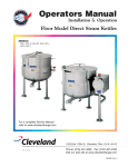
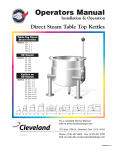
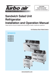
1
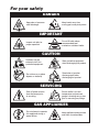
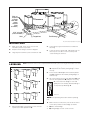
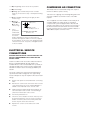
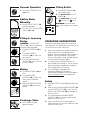
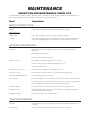
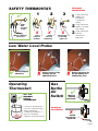
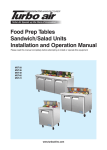
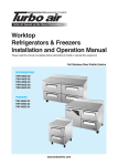
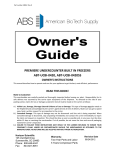
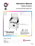
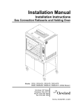
Operators Manual
Installation & Operation
Gas Floor Model Vertical Mixer Kettles
MODELS:
MKGL-40-T
MKGL-60-T
MKGL-80-T
MKGL-100-T
For units built prior to July 2010
MKGL-40-T
For a complete Service Manual
refer to www.clevelandrange.com
™
Cleveland
Enodis
1333 East 179th St., Cleveland, Ohio, U.S.A. 44110
Phone: (216) 481-4900 Fax: (216) 481-3782
Visit our web site at www.clevelandrange.com
SE55362 Rev. 5
FOR THE USER
IMPORTANT!
ENSURE KETTLE IS AT ROOM TEMPERATURE AND
PRESSURE GAUGE IS SHOWING ZERO OR LESS PRESSURE
PRIOR TO REMOVING ANY FITTINGS.
FOR YOUR SAFETY
DO NOT STORE OR USE GASOLINE
OR ANY OTHER
FLAMMABLE LIQUIDS AND
VAPOURS IN THE VICINITY
OF THIS OR ANY OTHER
APPLIANCE.
WARNING: Improper installation,
adjustment, alteration, service or
maintenance can cause property
damage, injury or death. Read the
installation and operating
instructions thoroughly before
installing or servicing this
equipment.
.
IMPORTANT
The following points are to insure the safe installation and operation of this equipment:
• Insure all gas and electrical supplies match rating plate and electrical stickers.
• Observe all clearance requirements.
• Disconnect the electrical power supply to the appliance before cleaning or servicing unit.
• All service must be performed by a qualified Cleveland Range Technician.
• Do not obstruct the flow of combustion and ventilation air.
The installation and connection must comply with current local codes, or in the absence of local codes, with
CAN/CGA-B149.1 and .2 installation code or with the national fuel gas code, ANSI Z223.1-L988.
Post in a prominent location, instructions to be followed in the event the user smells gas. This information shall
be obtained by consulting your local gas supplier.
The appliance and its individual shut off valve must be disconnected from the gas supply piping system during
any pressure testing of that system at test pressures in excess of 1/2 psig. (3.45 kpa).
The appliance must be isolated from the gas supply piping system by closing its individual manual shut off
valve during any pressure testing of the gas supply piping system at test pressures equal to or less than 1/2
psig. (3.45 kpa).
RETAIN THIS MANUAL FOR YOUR REFERENCE.
For your safety
DANGER
Keep clear of pressure
relief discharge.
Keep hands away from
moving parts and pinch points.
IMPORTANT
Do not fill kettle above
recommended level
marked on outside of kettle.
Inspect unit daily for
proper operation.
CAUTION
Surfaces may be
extremely hot! Use
protective equipment.
Wear protective equipment
when discharging hot product.
Do not lean on or place
objects on kettle lip.
Stand clear of product
discharge path when
discharging hot product.
SERVICING
Shut off power at main
fuse disconnect prior
to servicing.
0
Ensure kettle is at room
temperature and pressure
gauge is showing zero or less
prior to removing any fittings.
GAS APPLIANCES
Do not attempt to operate
this appliance during a
power failure.
Keep appliance and area free
and clear of combustibles.
INSTALLATION
INSPECTION
CLEARANCE REQUIREMENTS
Before unpacking visually inspect the unit for evidence
of damage during shipping.
This unit must be installed in accordance with the
clearances shown on the rating label which is adhered
to the unit.
If damage is noticed, do not unpack the unit, follow
shipping damage instructions.
FOR YOUR SAFETY. Keep the appliance area free and
clear of combustible materials.
SHIPPING DAMAGE
INSTRUCTIONS
GAS
If shipping damage to the unit is discovered or
suspected, observe the following guidelines in
preparing a shipping damage claim.
ENSURE THE GAS SUPPLY MATCHES THE
KETTLE'S REQUIREMENTS AS STATED ON THE
RATING PLATE.
1. Write down a description of the damage or the
reason for suspecting damage as soon as it is
discovered. This will help in filling out the claim
forms later.
It is recommended that a sediment trap (drip leg) be
installed in the gas supply line. If the gas pressure
exceeds 14” water column, a pressure regulator must
be installed, to provide a maximum of 14” water column
gas pressure to the gas control valve.
2. As soon as damage is discovered or suspected,
notify the carrier that delivered the shipment.
3. Arrange for the carrier's representative to examine
the damage.
4. Fill out all carrier claims forms and have the
examining carrier sign and date each form.
GENERAL
Installation of the kettle must be accomplished by
qualified installation personnel working to all applicable
local and national codes. Improper installation of
product could cause injury or damage.
This equipment is built to comply with applicable
standards for manufacturers. Included among those
approval agencies are: UL, A.G.A., NSF, ASME/N.Bd.,
CSA, CGA, ETL, and others. Many local codes exist,
and it is the responsibility of the owner/installer to
comply with these codes.
Observe all clearance requirements to provide proper
make-up air flow. Do not obstruct the flow of combustion
and ventilation air. Check rating plate to ensure that
kettle has been equipped to operate with the type of
gas available at the installation.
Connect the gas line to the manual valve located at the
rear of the control box.
Installation must be in accordance with local codes
and/or the National Fuel Gas Code ANSI Z223.1 Latest
Edition (USA) or the latest Installation Codes for Gas
Burning Appliances and Equipment CAN/ CGA B149.1
and CAN/ CGA B149.2 (Canada). Use a gas pipe joint
compound which is resistant to L.P. gas. Test all pipe
joints for leaks with soap and water solution. Ensure that
the gas pressure regulator is set for the manifold
pressure indicated on the gas rating plate.
The appliance and its individual shut-off valve must be
disconnected from the gas supply piping system during
any pressure testing of that system at test pressures in
excess of 1/2 psi (3.45 kPa). The appliance must be
isolated from the gas supply piping system by closing
its individual manual shut-off valve during any pressure
testing of the gas supply piping system at test
pressures equal to or less than 1/2 psi (3.45 kPa).
WATER
The sealed jacket of the gas-fired kettle is precharged
with the correct amount of a water-based formula, and
therefore, no water connection is required to the kettle
jacket. The kettle can be equipped with optional hot and
cold water taps, the taps require 1/2" copper tubing as
supply lines.
VENTILATION
Gas fired kettles are only to be installed under a
ventilation hood in a room which has provisions for
adequate make up air. Further information can be
obtained by referring to the U.S.A. National Fire
Protection Associations NFPA96 regulations. These
standards have also been adopted by the National
Building Code in Canada.
CLEANING
After installation the kettle must be thoroughly cleaned
and sanitized prior to cooking.
Shim as
required
to make
level with
center
console
(front
and back)
Jack
4"x4" or larger
(front and back)
Skid
Forklift tongs
Flanged feet
Recommended Installation Procedure
MOVING UNIT
1.
While still on skid, move unit as close to final
installation position as possible.
4.
Lower gently to ground and remove forklift and
blocking.
2.
Prepare unit for lifting as shown in diagram.
5.
3.
Lift gently with a forklift or jacks and remove skid.
If unit has to be re-positioned, slide gently. Do not
twist or push one side of unit excessively and
cause binding on trunnions.
Note: Instructions reflect a more complicated twin mixer kettle - process for single mixer kettles is the same.
LEVELING
B
A
B
A
C
C
C
C
C
C
2.
Level and straight-edge backs of consoles (dotted line
B). Adjustments are made by turning flanges on back
feet only.
3.
Level consoles individually from front to back (dotted
lines C). Adjustments are made by turning flanges on
front feet only.
4.
Re-check that the back is level (dotted line B) and
then the front (dotted line D). Adjust if necessary.
5. Check that mixer bridge is level and
guide pins lock smoothly without binding. If
not repeat steps 1 through 4.
D
D
Guide Pins
NOTE: See Operating Instructions before operating
unit.
Recommended Leveling Procedure
6. Make electrical connections (see electrical service
connections) and test mixer bridge as follows:
1.
⇒ A/ Raise mixer bridge.
With straight-edge, line the backs of the consoles
up with each other (dotted line A).
⇒ B/ Swing bridge out over centre console.
⇒ C/ Swing bridge to the left as far as possible.
⇒ D/ Lower bridge.
⇒ E/ Bridge pins should enter pin hole on kettle
perfectly, If not return to step 1 and repeat leveling
steps.
⇒ F/ Raise bridge and swing to far right (for twin
mixers only).
⇒ G/ Repeat
steps D and
E (for twin
mixers only).
4 7/8" (124mm)
120
120
7/16"Ø, 3 HOLES
7.
ON 3 1/8" (80mm) B.C.D.
Once
positioned
FLANGED FOOT DETAIL
and leveled,
(REAR LEGS ONLY)
permanently
secure the
kettle's flanged feet to the floor using 5/16 inch
stainless steel lag bolts and floor anchors (supplied
by the installer). Secure each of the flanged feet with
one bolt in each hole. Seal joints of flanged feet with
a silicone sealant.
ELECTRICAL SERVICE
CONNECTIONS
ENSURE THE ELECTRICAL SUPPLY MATCHES THE
KETTLE'S REQUIREMENTS AS STATED ON THE
RATING LABEL.
Install in accordance with local codes and/or the National
Electric Code ANSI/NFPA No 70-1981 (USA) or the
Canadian Electric Code CSA Standard C22.1 (Canada). A
separate fused disconnect switch must be supplied and
installed. The kettle must be electrically grounded by the
installer.
The electric supply must match the power requirements
specified on the kettle's rating plate. The copper wiring
must be adequate to carry the required current at the rated
voltage.
1.
Ensure main power is turned off before connecting
wires.
2.
Remove the screws at the rear of the mixer console
cover, and remove the cover. A wiring diagram is
affixed to the underside of the console cover.
3.
Feed permanent copper wiring 18" through the cutout in the bottom of the console. Connect wiring in
junction box in the bottom of the console.
4.
Turn main power back on.
5.
Check for correct rotation of electric motor (access
by removing top front cover on center console). If
rotation is incorrect, disconnect main power and
reverse any two of the three live lines.
6.
Replace the console cover and secure it with
screws.
COMPRESSED AIR CONNECTION
Mixer Kettles with an air activated discharge valve require a
minimum of 90 PSI to operate correctly.
If the unit is also supplying air to a Metering Filling Station then
a pressure of 100 PSI at a minimum volume of 25 CFM is
required.
The air supplied to the mixer should be clean and dry. No oil
should be added to the supply air. We recommend the
compressed air system be equipped with a drier, filter, and
automatic water dump on the air compressor receiver tank. If
the distance between the tank and the unit is less than 100
feet then a minimum line size of 3/4" is required. A distance of
100 to 300 feet requires a minimum 1" line.
QUALITY ASSURANCE CHECKS
INSTALLATION
1. Visual
Examine unit for scratches, dents, or other defects.
2. Visual
Check flanged feet all have bolts holding them.
3. General
Check all accessible wiring, mechanical and plumbing connections by hand for secure,
tight and satisfactory assembly. Remove all paper.
4. Level
Check unit has been leveled and squared correctly.
KETTLE
Although the kettle has been thoroughly tested before leaving the factory, the installer is responsible for ensuring the
proper operation of kettle once installed.
DO NOT ATTEMPT TO OPERATE THIS APPLIANCE DURING A POWER FAILURE.
KEEP APPLIANCE AND AREA FREE AND CLEAR OF COMBUSTIBLES.
1.
Before turning the kettle on, read the vacuum/pressure gauge. The gauge's needle should be in the green zone.
If the needle is in the "VENT AIR" zone, follow air venting procedure.
2.
Supply power to the kettle by placing the fused disconnect switch to the "ON" position.
3.
Turn on main gas supply to unit. Open the kettle's shut-off valve (located at back of console).
4.
Turn the temperature control knob to "1`" (Min.). The green LED light should remain lit, indicating the burner is lit, until the
set temperature is reached. Then the green light will cycle on and off, indicating the burner is cycling on and off to
maintain temperature.
5.
Tilt the kettle forward. After a few seconds the red "LOW WATER" light should be lit when the kettle is in a tilted
position. This light indicates that the burner has automatically been shut off by the kettle's safety circuit. This is a
normal condition when the kettle is in a tilted position.
6.
Raise the kettle to the upright position. The red "LOW WATER" light should go out when the kettle is upright.
7.
Turn the temperature control knob to "10" (Max.) and allow the kettle to preheat. The green light should remain on
until the set temperature is reached. Then the green light will cycle ON and OFF, indicating the burner is cycling
ON and OFF to maintain temperature
MIXER
1. Raise Bridge
If bridge does not raise then check motor rotation. Bridge should not raise until speed control
is turned to minimum and then adjusted back up.
2. Swing Bridge
Bridge when fully raised should swing without hitting any object, i.e. control housing,
kettle lip. Check that hydraulic hoses are not being pinched by stops on swivel assembly.
3.
Kettle tilts smoothly both down and back up. If power tilt, check that micro switches are
adjusted properly (kettle is level in upright position and drains fully when tilted) and are
not being crushed by gear.
Tilt Kettle
4. Lower Bridge
Raise bridge. Switch to mix. Turn speed control to zero to reset micro switch then set
speed control to number four. Check that unit does not begin to mix until bridge has
lowered part way into the kettle. Check that mixer bridge pin lowers into pin hole correctly
5. Speed Control Main
Main agitator arm not rotating when set at "0" but will start to move slowly on
"1" . Speed control makes positive contact with micro switch.
6. Speed Control Secondary
Set main speed control to five. Adjust secondary control from
minimum to maximum. Look for considerable speed variance.
7. Water Faucets
Turn on hot water faucet. Turn off and check for leaks in piping and drips from
faucet spout. Repeat above with cold water faucet.
8. Product Discharge
Valve
Add water to kettle. Check for leaks from valve. Open and close valve a few times
and check for leaks again.
OPERATING INSTRUCTIONS
18
19
21
15
6
20
23
22
16
17
10
11
1
2
3
12 13 14
4
9
7
8
5
Operating Controls & Indicators
ITEM #
DESCRIPTION
FUNCTION
1.
Low Water Indicator Light (Red)
2.
On-Off Switch/
Solid State
Temperature Control
Heat Indicator Light (Green)
When lit, indicates that the kettle is low on water and will not operate
in this condition. This will also light when the kettle is tilted.
Turns kettle ON/OFF and allows the operator to adjust the kettle
temperature in increments from 1 (Min.) to 10 (Max.).
3.
4.
5.
Ignition Failure Indicator Light
(Amber)
Vacuum/Pressure Gauge
6.
Pressure Relief Valve
(not shown)
7.
8.
Water Level Sight Glass
Tilt Wheel
9.
10.
11.
12.
13.
14.
15.
16.
17.
18.
19.
20.
21.
22.
23.
Butterfly Valve
Mixer Speed Control
Emergency Stop
Main Power Switch
Mix/Lift Switch
Up/Down Switch
Faucet Spout
Cold Water Valve
Hot Water Valve
Mixer Bridge
Main Agitator Arm
Secondary Arm
Scraper Blades
Secondary Speed Control
Temperature Probe
When lit, indicates that the kettle's burner is on.
Cycles ON-OFF with burner.
Indicates failure of heating system to ignite.
(Used prior to July 2004)
Indicate steam pressure in PSI inside steam jacket as well as
vacuum in inches of mercury.
This valve is used to vent the kettle and in the unlikely event there is
an excess steam build-up in the jacket, this valve opens
automatically to relieve this pressure.
Displays water level in steam jacket.
Used for tilting the kettle on hand tilt models. In power tilt models
there is a toggle switch in same location.
Used for draining product or wash water from kettle.
Controls speed of agitators and mixer bridge lift mode.
Stops hydraulic system.
Power switch for unit.
Sets hydraulics to mix or lift mode.
When unit is in lift mode, bridge can be raised or lowered with this switch.
Delivers water to the kettle.
Turns on cold water.
Turns on hot water.
Encloses agitator motors.
Provides most of the product movement.
Provides reverse agitation and product lift in kettle.
Scrapes the side of the kettle and moves product away.
Controls speed of secondary agitator arm.
Probe holds temperature sensors for controller.
OPERATING THE KETTLE
Do not attempt to operate this
appliance during a power failure.
!
Keep appliance and area free and
clear of combustibles.
NOTE: The red Low Water Indicator Light (1) should
not be lit when the kettle is in the upright position during
kettle operation. This light indicates that the burners
have been automatically shut off by the kettle's safety
circuit. It is, however, normal for the red light to come on
when the kettle is in a tilted position.
5.
Do not lean on or place objects on kettle lip.
Serious injury could result if kettle tipped over,
spilling hot contents.
If you are cooking an egg or milk product,
do not pre-heat kettle.
1.
2.
Before turning kettle on, read the Vacuum/Pressure
Gauge (5). The gauges needle should be in the
green zone. Once heated, the kettle's normal
maximum operating pressure is approximately 10 12 psi while cooking a water base product.
Ensure that the electrical service to the kettle is
turned on at the fused disconnect switch.
Temperature
Control
Setting
1.
2.
3.
4.
5.
6.
7.
8.
9.
10.
Approximate
Product Temperature
°F
°C
120
49
135
57
150
66
165
74
180
82
195
91
210
99
225
107
245
118
265
130
NOTE: Certain combinations of ingredients will result in temperature variations.
Temperature Range Chart
3.
Preheat the kettle by turning the ON/OFF
Switch/Solid State Temperature Control (2) to the
desired temperature setting (see above
"Temperature Range Chart"). The Heat Indicator
Light (Green) (3) will remain lit, indicating the
burner is on, until the temperature setting is
reached. When the green light goes off, the
burners are off, and preheating is complete.
NOTE: When cooking egg and milk products, the kettle
should not be preheated, as products of this nature
adhere to hot cooking surfaces. These types of food
should be placed in the kettle before heating is begun.
4.
NOTE: A five minute complete shut-of period is
required before relighting.
6.
Cooking
Place food product into the kettle. The green Heat
Indicator Light (3) will cycle on and off indicating
the burners are cycling on and off to maintain the
set temperature.
NOTE: Do not fill kettle above
recommended level marked on outside
of kettle.
When cooking is completed turn On/Off
Switch/Solid State Temperature Control (2) to the
"OFF' position.
Pour the contents of the kettle into an appropriate
container by tilting the kettle forward. Care should
be taken to pour slowly enough to avoid splashing
off the product.
NOTE: As with cleaning food soil from any cookware,
an important part of kettle cleaning is to prevent food
from drying on. For this reason, cleaning should be
completed immediately after cooked foods are
removed.
Approximate Boiling Times
The accompanying chart shows approximate times
required for gas kettles of various capacities to boil
water with the lid open. The ON/OFF Switch/Solid State
Temperature Control (2) must be set at “10” throughout
the heat-up period. Water will boil about 1/3 faster if the
kettle is filled only to the outer steam jacket’s welded
seam resulting in a kettle filled to 2/3 capacity.
Kettle Capacity
40 gallon
60 gallon
80 gallon
100 gallon
Approximate Boiling Times
Minutes
35
47
60
75
OFF
ON
General Operation
Tilting Kettle
1. Turn MAIN POWER SWITCH
(12) to "ON".
1. Raise MIXER BRIDGE (18)
and swing to side.
2. For manual tilt: turn TILT
WHEEL (8).
3. For power tilt: turn switch
"
" to raise, or "
" to tilt.
Adding Water
Manually
WARNING- Do not tilt kettle
when mixer agitators are in kettle
bowl.
1. Locate FAUCET SPOUT (15)
over desired kettle.
2. Turn on HOT or COLD WATER
VALVES (16 or 17).
OFF
MIX
LIFT
Lifting & Lowering
Bridge
OPERATING SUGGESTIONS
WARNING- Insure FAUCET
SPOUT (15) is out of way before
raising or lowering bridge.
Cleveland Range Mixer Kettles are simple and
safe to operate. The following tips will allow you to
maximize the use of your new mixer.
1. Turn MIX/LIFT SWITCH (13) to
"LIFT".
UP
OFF
DOWN
2. Turn MIXER SPEED
CONTROL (10) to "MIN" and
back up to #5.
3. Turn and hold UP/DOWN
SWITCH (14) "UP" to raise or
"DOWN" to lower.
OFF
MIX
LIFT
Mixing
1. Turn MIX/LIFT SWITCH (14) to
"MIX".
2. Turn MIXER SPEED
CONTROL (10) to "MIN" and
slowly adjust to desired
speed.
3. Adjust SECONDARY SPEED
CONTROL (22) to desired
speed.
Discharge Valve
2. Push handle in and pull
upwards to open.
1. Allow unit to preheat before addition of product to
kettle. However when cooking egg and milk
products, the kettle should NOT be preheated, as
products of this nature adhere to hot cooking
surfaces. These types of foods should be placed
in the kettle before heating is begun.
2. An important part of kettle cleaning is to
prevent foods from drying on. For this reason,
cleaning should be completed immediately
after cooked foods are removed.
3. If a mixer bridge is equipped with a
temperature probe for a controller or
thermometer, the probe must be submerged a
minimum of three inches in the product for
accurate readings.
Safety
1. Close BUTTERFLY VALVE (9) before filling the
kettle.
2. When raising or lowering MIXER BRIDGE (18),
insure FAUCET SPOUT (15) is not in the way
of MAIN AGITATOR ARM (19) or damage to
spout will result.
3. As a safety precaution the MIXER SPEED
CONTROL (10) must first be turned to zero
before unit will start to mix.
4. Always remember, like a cooking pot the
kettles become very hot when cooking. Avoid
contact with bare skin.
CLEANING INSTRUCTIONS
CLEANING INSTRUCTIONS
CAUTION
SURFACES MAY
BE EXTREMELY HOT!
CARE AND CLEANING
Cooking equipment must be cleaned regularly to
maintain its fast, efficient cooking performance and
to ensure its continued safe, reliable operation. The
best time to clean is shortly after each use (allow
unit to cool to a safe temperature).
WARNINGS
➩
2. Remove drain screen (if applicable). Thoroughly
wash and rinse the screen either in a sink or a
dishwasher.
3. Prepare a warm water and mild detergent solution in
the unit.
4. Remove food soil using a nylon brush.
5. Loosen food which is stuck by allowing it to soak at
a low temperature setting.
6. Drain unit.
7. Rinse interior thoroughly.
Do not use detergents or
cleansers that are chloride
based or contain quaternary
salt.
Chloride Cleaners
➩
1. Turn unit off.
Do not use a metal bristle
brush or scraper.
8. If the unit is equipped with a Tangent Draw-Off
Valve, clean as follows:
a) Disassemble the draw-off valve first by turning
the valve knob counter-clockwise, then turning
the large hex nut counter-clockwise until the
valve stem is free of the valve body.
b) In a sink, wash and rinse the inside of the valve
body using a nylon brush.
c) Use a nylon brush to clean tangent draw-off tube.
d) Rinse with fresh water.
e) Reassemble the draw-off valve by reversing the
procedure for disassembly. The valve's hex nut
should be hand tight only.
Wire Brush &
➩
Steel wool should never be
used for cleaning the stainless
steel.
9. If the unit is equipped with a Butterfly Valve, clean
as follows:
a) Place valve in open position.
b) Wash using a warm water and mild detergent
solution.
Steel Pads
➩
c) Remove food deposits using a nylon brush.
Unit should never be cleaned
with a high pressure spray
hose.
d) Rinse with fresh water.
e) Leave valve open when unit is not in use.
10. Using mild soapy water and a damp sponge, wash
the exterior, rinse, and dry.
NOTES
High Pressure
Spray Hose
➩
Do not leave water sitting in unit
when not in use.
➩ For more difficult cleaning applications one of the
following can be used: alcohol, baking soda, vinegar,
or a solution of ammonia in water.
➩ Leave the cover off when the kettle is not in use.
Stagnant
Water
➩ For more detailed instructions refer to the Nafem
Stainless Steel Equipment Care and Cleaning manual
(supplied with unit).
STAINLESS STEEL EQUIPMENT CARE AND CLEANING
(Suppied courtesy of Nafem. For more information visit their web site at www.nafem.org)
to reduce deposits. There are certain filters that can be installed to
remove distasteful and corrosive elements. To insure proper water
treatment, call a treatment specialist.
Contrary to popular belief, stainless steels ARE susceptible to rusting.
Corrosion on metals is everywhere. It is recognized quickly on iron and
steel as unsightly yellow/orange rust. Such metals are called “active”
because they actively corrode in a natural environment when their atoms
combine with oxygen to form rust.
Stainless steels are passive metals because they contain other metals, like
chromium, nickel and manganese that stabilize the atoms. 400 series
stainless steels are called ferritic, contain chromium, and are magnetic;
300 series stainless steels are called austenitic, contain chromium and
nickel; and 200 series stainless, also austenitic, contains manganese,
nitrogen and carbon. Austenitic types of stainless are not magnetic, and
generally provide greater resistance to corrosion than ferritic types.
5. Keep your food equipment clean.
Use alkaline, alkaline chlorinated or non-chloride cleaners at
recommended strength. Clean frequently to avoid build-up of hard,
stubborn stains. If you boil water in stainless steel equipment,
remember the single most likely cause of damage is chlorides in the
water. Heating cleaners that contain chlorides have a similar effect.
6. Rinse, rinse, rinse.
If chlorinated cleaners are used, rinse and wipe equipment and
supplies dry immediately. The sooner you wipe off standing water,
especially when it contains cleaning agents, the better. After wiping
equipment down, allow it to air dry; oxygen helps maintain the
stainless steel’s passivity film.
With 12-30 percent chromium, an invisible passive film covers the steel’s
surface acting as a shield against corrosion. As long as the film is intact
and not broken or contaminated, the metal is passive and stain-less. If the
passive film of stainless steel has been broken, equipment starts to
corrode. At its end, it rusts.
7. Never use hydrochloric acid (muriatic acid) on stainless steel.
Enemies of Stainless Steel
8. Regularly restore/passivate stainless steel.
There are three basic things which can break down stainless steel’s
passivity layer and allow corrosion to occur.
Recommended cleaners for specific situations
1. Mechanical abrasion
Job
Cleaning Agent
Comments
2. Deposits and water
Routine cleaning
Soap, ammonia,
detergent, Medallion
Apply with cloth or sponge
Fingerprints & smears
Arcal 20, Lac-O-Nu
Ecoshine
Provides barrier film
Stubborn stains &
discoloration
Cameo, Talc, Zud,
First Impression
Rub in direction of polish lines
Grease & fatty acids,
blood, burnt-on-foods
Easy-off, De-Grease
It Oven Aid
Excellent removal on all finishes
Grease & oil
Any good
commercial detergent
Apply with sponge or cloth
Restoration/Passivation
Benefit, Super Sheen
3. Chlorides
Mechanical abrasion means those things that will scratch a steel surface.
Steel pads, wire brushes and scrapers are prime examples.
Water comes out of the faucet in varying degrees of hardness. Depending
on what part of the country you live in, you may have hard or soft water.
Hard water may leave spots, and when heated leave deposits behind that
if left to sit, will break down the passive layer and rust stainless steel. Other
deposits from food preparation and service must be properly removed.
Chlorides are found nearly everywhere. They are in water, food and table
salt. One of the worst chloride perpetrators can come from household and
industrial cleaners.
Review
So what does all this mean? Don’t Despair!
Here are a few steps that can help prevent stainless steel rust.
1. Use the proper tools.
When cleaning stainless steel products, use non-abrasive tools. Soft
cloths and plastic scouring pads will not harm steel’s passive layer.
Stainless steel pads also can be used but the scrubbing motion must
be in the direction of the manufacturers’ polishing marks.
2. Clean with the polish lines.
Some stainless steel comes with visible polishing lines or “grain.”
When visible lines are present, always scrub in a motion parallel to the
lines. When the grain cannot be seen, play it safe and use a soft cloth
or plastic scouring pad.
3. Use alkaline, alkaline chlorinated or non-chloride containing cleaners.
While many traditional cleaners are loaded with chlorides, the industry
is providing an ever-increasing choice of non-chloride cleaners. If you
are not sure of chloride content in the cleaner used, contact your cleaner
supplier. If your present cleaner contains chlorides, ask your supplier if
they have an alternative. Avoid cleaners containing quaternary salts; it
also can attack stainless steel and cause pitting and rusting.
4. Treat your water.
Though this is not always practical, softening hard water can do much
1. Stainless steels rust when passivity (film-shield) breaks down as a
result of scrapes, scratches, deposits and chlorides.
2. Stainless steel rust starts with pits and cracks.
3. Use the proper tools. Do not use steel pads, wire brushes or scrapers
to clean stainless steel.
4. Use non-chlorinated cleaners at recommended concentrations. Use
only chloride- free cleaners.
5. Soften your water. Use filters and softeners whenever possible.
6. Wipe off cleaning agent(s) and standing water as soon as possible.
Prolonged contact causes eventual problems.
To learn more about chloride-stress corrosion and how to prevent it,
contact the equipment manufacturer or cleaning materials supplier.
Developed by Packer Engineering, Naperville, Ill., an independent testing
laboratory.
MAINTENANCE
INSPECTION AND MAINTENANCE CHECK LIST
Cleveland Range equipment requires little preventative maintenance. We do however provide the following chart as a
guide line for inspection and maintenance to keep your unit functioning at 100%.
Item
Inspection
MONTHLY INSPECTIONS
Switches
Inspect switches for damage and correct operation. Replace as required.
Product Drain Valves
Butterfly Valve
Inspect parts for damage. Test valve for leakage. Replace as required.
Air Valve
Inspect parts for damage. Test valve for leakage. Check valve seals for air leakage. Inspect
supply hose and fittings. Replace as required. Inspect air filter and replace if required.
SIX MONTH MAINTENANCE
Lubrication
Grease trunnion housings and gear/worm assembly as recommended in Lubrication
Instructions.
Grease bridge swivel assembly.
Use "Never Seize" on tilt worm and gear.
Kettle Console Cover
Inspect gasket material for integrity. Replace if necessary.
Insure all screws are in place and firmly holding down the cover.
If not replace/tighten screws.
Hand wheel (hand tilt models only)
Check hand wheel for tightness. If loose tighten allen screw.
Tilting (tilting models only)
Check that kettle tilts smoothly. Grease as described in Lubrication Procedure.
On-Off Switch/Temperature Control
Check for damage. Replace if necessary.
Pressure Gauge
Check that the gauge does not have moisture on its inside face. Replace if moisture is present.
Check that the gauge shows a vacuum (needle is well into the Green zone) when cold and shows
between 25-40 psi when unit is hot. If not follow Vacuum Leak Test Procedure.
Pressure Relief Valve
Check pressure relief valve as described in Pressure Relief Valve Testing Procedure .
Temperature Check
Following Calibrating Procedure check the inner kettle surface temperature with a digital
surface thermometer. Adjust if required.
Gear/Worm Assembly
Inspect for play. Tighten Allen screws if required.
YEARLY MAINTENANCE
Lubrication
Drain hydraulic oil and remove filter. Replace oil and filter (see Hydraulic Oil Replacement
Procedure).
Solenoid Valves
Inspect solenoid valves for proper operation. Clean or replace as required.
Kettle Safety Inspection Checklist
Just recently a competitor’s steam jacketed kettle exploded causing serious
personal injury and damage to a kitchen. In most cases these accidents are caused by
poor maintenance and/or incorrect installation.
We at Cleveland would like to restate that regular inspection and maintenance of units is essential to
obtain trouble free and safe operation of equipment. Inspections must include testing of the pressure relief
valve and checks of the operating system to insure that it has not been altered.
No safety features designed into the equipment should ever be tampered with. Tampering
with or bypassing controls is a very dangerous practice and unfortunately we have seen several cases of this.
Following is a short list of the most common and the most dangerous alterations performed on kettles.
SAFETY VALVE:
1
✘
Plug
✔
✔
✔
✔
2
The above illustrations show the three variations
of factory installed Safety Valves.
Any modifications are unacceptable.
Incorrect Installations
1
Safety valve has plug threaded into the discharge opening
preventing any steam from escaping.
2
Safety valve’s tube diameter has been reduced.
3
Safety valve is sticking, frozen shut or plugged. To test, refer to Service
Bulletin SE90038 rev. 2, “Pressure Relief Valve Periodic Testing”.
4
Safety valve is plumbed to a drain or water line creating back
pressure and reducing flow.
3
✘
Tube
diameter
reduced
✘
Frozen,
stuck, or
plugged
✘
4
Plumbed to
drain or
water line
SE90047
SAFETY THERMOSTAT:
1
✔
Probe
fully
inserted
in tube
Wiring is properly
connected
✘
Probe
removed
partially
Incorrect
Installations
2
✘
Probe
removed
completely
3
✘
Thermostat
electrically
bypassed
1
Safety thermostat
probe is not
completely
inserted into
tubing.
2
Safety thermostat
probe is removed
from tubing.
3
Safety thermostat
electrical
connection is
bypassed.
Low Water Level Probe:
(A)
(B)
✔
Probe properly
attached
✘
Probe bypassed by
running (A) an
additional wire
Operating
Thermostat:
265º
✔
260º - 270º
MAXIMUM
KETTLE
TEMPERATURE
If maximum temperature is
not in this range (on empty
kettle), refer to the
“Calibrating Procedure” in
the unit’s Installation,
Operation & Service Manual.
Gas
Kettle
Air
Switch
Incorrect
Installation
✘
Probe bypassed by
(B) grounding the
connecting wire
✔
Wiring is
properly
connected
✘
Switch
electrically
bypassed
SE90047