1
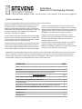
Instructions Model CD-77 Peak Reading Voltmeter 111 W Greenwood Ave Waukegan, IL 60087 phone 847 336 9375 fax 847 662 6808 email [email protected] GENERAL INFORMATION The CD-‐77 is a peak reading voltmeter (o^en referred to as DVA) designed specifically for tes;ng CD igni;on systems. The meter has three scales: 0-‐5, 0-‐50 and 0-‐500, corresponding to the se`ngs of the right hand range selector switch. The le^ hand switch selects sensor posi;on for measuring trigger voltages and the other two posi;ons select polarity of the voltage to be measured, either posi;ve or nega;ve. and connec;ons. Jumper wires are furnished for tests on the connector type systems. Three of the jumpers have single terminals for straight through connec;ons between plugs. The other two jumpers are “piggy-‐back” types with an extra terminal so that the meter can be plugged in for readings with the system in opera;on. Using one of the Stevens adaptors precludes the need for jumpers on most engines. Remember that switch posi;ons on SA-‐77, SA-‐5 and SA-‐6 adaptors ON or OFF, are cri;cal to obtaining proper test results. The test leads have pin type termina;ons which can be plugged directly into the connectors used with the OMC connector type systems. A plug-‐in clip is also furnished with the black test lead for use when it is necessary to clip to a ground. The CD-‐77 may be used to read peak voltage on any engine for Overload protec;on is provided by an internal protec;on circuit; which peak voltage (or DVA) specifica;ons are available. In however, if the needle swings hard against the right end of the addi;on, the following instruc;ons cover all basic types of OMC scale or vibrates against the le^ end of the scale, disconnect or CD systems, from early baMery CD to early 90's. stop cranking as quickly as possible and recheck switch se`ngs SENSOR NOTE: All original peak voltmeters were made with a Sensor posi;on (SEN). This posi;on is more sensi;ve on the CD-‐77 than on other brands, so you may expect unusually high readings on some engines. This is okay as long as readings meet the minimum spec. Some manuals call for tes;ng sensors on the POS posi;on. This is only to accommodate testers which lack a sensor posi;on; con;nue to use the SEN posi;on on the CD-‐77 for all sensor tests. SYSTEM TYPE PAGE BaMery CD 2 Pack Terminal Systems (Magneto CD with screw terminals on pack) 2 CONNECTOR SYSTEMS 4-‐11 2 & 4 cylinder through 1988 Except 1988 Loop V 4 3 & 6 cylinder through 1988 Except 1988 Loop V 5 V-‐8 through 1987 7 1987-‐90 2.5, Ultra 4, Excel 4 (Mag CD, single pins on pack, external magnets) 8 1989-‐90 2 cylinder CD2 UL (Mag CD, pack under flywheel) 8 1989-‐90 3 cylinder 9 1988-‐90 Cross V 9 1988-‐90 Loop V 11 1 Heads Up: When using a spark checker, be sure it is an open gap tester and not one which sparks across the surface of a board. Sparks burn a carbon path on boards, allowing a very weak spark to look good. Gap se`ngs on such a spark checker are meaningless. BATTERY CD Following is a general test procedure for baMery CD systems. Refer to manuals or diagrams for specific engines if addi;onal informa;on is required. Note: BaMery should be fully charged before proceeding with tests. The CD-‐77 is not a DC voltmeter and will read slightly lower than actual voltage. Take an ini;al reading directly across a fully charged baMery to determine the exact CD-‐77 reading. PACK INPUT TEST Set Meter: POS – 50 Connect black test lead to engine ground. Connect red test lead to pack input wire with pack connected. With igni;on on, reading should be same as baMery voltage (approximately 11 or more). Crank engine. Reading should not drop more than 2 ½ volts. If there is no voltage or low voltage at pack input, trace back point to point with red test lead through connectors, terminals, wires, igni;on switch etc. (safety switch or voltage suppressor on some models) to locate point of failure. PACK OUTPUT TEST Set Meter: POS – 500 Connect black test lead to engine ground. Connect red test lead to coil primary, leaving coil connected. Coils should remain connected to avoid damage to packs. Crank engine. Reading should be 250 volts or higher. If no reading: Sensor equipped engines Subs;tute a test sensor and ac;vate. If reading is okay with test sensor, check engine sensor leads, gap, cracks on sensor face etc. If no reading with test sensor, disconnect igni;on coil and check with coil analyzer. If coil is okay, pack is bad. Breaker point engines Disconnect igni;on coil and check on coil analyzer..If coil is okay, reconnect to pack. Reconnect red test lead to coil. Disconnect wire between pack and points. With key switch on, touch amplifier connector to ground intermiMently. No reading, pack is bad. Reading okay, trouble is in breaker point circuit. PACK TERMINAL SYSTEMS NOTE: V-‐6 engines are tested same as Power Pack III, one side at a ;me. When tes;ng one side, remove key switch lead (black/yellow stripe) from pack on other side and insulate with tape. BaMery must be fully charged before tes;ng. SPARK TEST Remove high tension spark plug leads from spark plugs and connect to spark checker. Set gap on spark checker according to service manual. Crank engine. If spark jumps each gap alternately, igni;on system is okay. Check spark plugs and other engine systems. If weak, erra;c or no spark from one coil, go to sensor test. If weak or erra;c spark from ALL coils go to charge coil test. If no spark from all coils, go to key switch test. KEY SWITCH TEST Remove black/yellow stripe lead from power pack terminal. Crank engine and observe spark. Spark okay on all coils, trouble is in key switch or key switch lead. No spark from any coil, leave key switch lead disconnected and go to Charge Coil Test. Spark on only one igni;on coil, one problem is in key switch or switch lead. Repair problem and go to Sensor Test. 2 CHARGE COIL OUTPUT TEST Set Meter POWER PACK II POWER PACK III NEG – 500 POWER PACK IV Remove brown lead from power pack Remove brown lead and brown/orange terminal 1. Connect red probe to brown stripe lead from terminals 4 & 5. Connect lead. Connect black probe to engine red probe to brown lead . Connect black ground. probe to brown/orange. Crank engine. Meter should read 230 or higher. If reading okay, charge coils okay If reading low, check resistance of charge coils. Remove brown lead and brown/yellow stripe lead from terminals 7 & 8. Connect red probe to brown lead. Connect black probe to brown/yellow. If resistance out of spec, replace charge coils If resistance okay, replace flywheel. POWER PACK II POWER PACKS III AND IV Reconnect brown lead to terminal 1 and Con;nue with charge coil short to go to Sensor Test. ground test. CHARGE COIL SHORT TO GROUND TEST Set Meter: NEG – 500 Connect black meter lead to ground and leave red meter lead connected to brown wire. Crank engine. Move red meter lead to other charge coil lead (brown/orange or brown/yellow) and repeat. If no meter reading on both checks, charge coils are okay. Go to Sensor Test. If there is any meter reading above zero, charge coils are grounded. Reconnect charge coil leads to power pack. SENSOR COIL OUTPUT TEST Set Meter: SEN – 5 Note: If spark is present at spark checker during sensor tests, replace power pack. POWER PACK II Remove both sensor leads from terminals 6 & 7. Connect red probe to either lead and black probe to the other. POWER PACK III Remove sensor leads from terminals 8, 9, 10 and 11. Connect black probe to black/white stripe lead removed from terminal 11. Connect red probe to lead removed from terminal 8. POWER PACK IV Remove sensor leads from terminals 2, 4, 9 and 12. Connect red probe to lead removed from terminal 2. Connect black probe to lead removed from terminal 4. Crank engine. Meter should read .3 or higher. POWER PACK II POWER PACK III POWER PACK IV Reverse meter leads and repeat test Move red probe to sensor lead from 9 Reverse probes and repeat test. and repeat test, then to lead from 10 and Then change probes to leads from 9 repeat. and 12 and repeat above steps. If reading okay, con;nue with Short to Ground Test. If reading low, check sensor resistance. If low resistance, replace sensor. If resistance okay, problem can be too large sensor air gap, weak sensor magnets in flywheel or too low cranking speed. SENSOR SHORT TO GROUND TEST Set Meter: SEN – 5 Connect black probe to ground. Connect red probe to each of the sensor leads one at a ;me and crank engine. If no reading, con;nue with Power Pack Output Test. If any reading above zero, sensors are grounded. Repair or replace. Reconnect sensor leads to proper power pack terminals. POWER PACK OUTPUT TEST Set Meter: NEG – 500 Connect black meter lead to engine ground. 3 POWER PACK II Connect red probe to power pack terminal 2 and crank engine. Meter should read 180 or more. Repeat with red probe at terminal 3. POWER PACK III Connect red probe to power pack terminal 1 and crank engine. Meter should read 170 or more. Repeat with red probe at terminals 2 and 3. POWER PACK IV Connect red probe to power pack terminal 3 and crank engine. Meter should read 170 or more. Repeat with red probe at terminals 5, 10 & 11. Readings okay but s;ll no spark, check igni;on coil(s). If pack readings low, disconnect coil primary from pack (one at a ;me) and connect red probe to terminal. Crank engine. If reading low, pack is defec;ve. If reading okay, check igni;on coil(s). If coil(s) okay, pack is defec;ve. FINAL TEST Make a final spark test of the en;re igni;on system with all leads connected to the power pack. CONNECTOR SYSTEMS 2 & 4 cylinder through 1988 except 1988 Loop V The following is a systema;c procedure for checking the CD II igni;on system. Whenever possible, it is recommended that service manual procedures be followed. An addi;onal test in the V-‐4 manuals covers “Rough Running Engines”. Readings used here are based on hand cranking through 1984 and on starter cranking therea^er. VISUAL INSPECTION Check wiring for broken, pinched or loose leads, connector misalignment, etc. SPARK TEST Remove high tension leads from spark plugs and connect to spark checker. Spark checker remains connected for all other tests. Set gap to ½ inch. Crank engine. If spark jumps each gap alternately, igni;on system is okay. Check spark plugs and other engine systems. If no spark, go to key switch or stop buMon elimina;on test in service manual. If spark at only one gap, go to resistance tests for charge coils and sensor coils in service manuals. CHARGE COIL OUTPUT TEST Set Meter: NEG – 500 Disconnect connector between armature plate and pack..... Insert probes in connector from armature plate..... 2 cylinder, pre-‐1985 2 cylinder, 1985 and later V-‐4 Red to A, Black to D Red to A, Black to D Red to A, Black to B 4-‐wire 5-‐wire 2-‐wire Crank engine. Meter should read minimum: 2 cylinder V-‐4 pre-‐1985 V-‐4 1985 and later dual pack single pack Cross V 1988 If reading okay, check for short to ground. If no reading, replace charge coil. If low reading, check resistance of charge coil. If resistance low, replace charge coil. If resistance okay, replace flywheel CHARGE COIL SHORT TO GROUND TEST Set Meter: NEG – 500 Use same connectors as for Output Tests above. Connect black probe to stator base. Connect red probe to: 2 cylinder -‐ A then repeat to D V-‐4 -‐ A then repeat to B 4 230 160 150 175 150 Crank engine. If there is any reading, charge coil is shor;ng to ground. If there is no reading. go to Sensor Tests. SENSOR OUTPUT TEST Set Meter: SEN – 5 NOTE: Because of its sensi;vity on Sensor se`ng, the CD-‐77 will generally read considerably higher than the figures given in the service manuals, par;cularly on smaller engines where cranking speeds are higher. Disconnect between stator and pack..... 2 cyl, pre-‐1985 4-‐wire 1985 and later 5-‐wire V-‐4 dual pack 4-‐wire single pack 5-‐wire Connect jumpers between terminals..... A to A, D to D A to A, D to D None None Connect meter leads to..... Black B, Red C, then reverse Black B, Red C, then reverse Black A, Red B. Repeat with Red to C Black E, Red A. Repeat with Red to B, C & D Crank engine. Meter should read: .3 or higher 2V for 1986 2 cylinder engine 1.5V for 1987-‐88 2 cylinder If reading okay, check for short to ground. If no reading, defec;ve sensor. SENSOR SHORT TO GROUND TEST Set Meter: SEN – 5 Remove black probe from connector and clip to armature plate (ground). Connect red probe to: 2 cylinder: B, then repeat to C V-‐4 dual pack: A, then repeat to B & C single pack All 5 terminals Crank engine. If any reading is present on meter, sensor is shorted to ground. If no short, con;nue with pack test. PACK TESTS Set Meter: NEG – 500 Disconnect between pack and & coil: Pre 1985, 2 cylinder: 3-‐wire connector: V-‐4: 2-‐wire connector 1985 and later, 2 cylinder & V-‐4 have direct connec;ons. Use TS-‐77 terminal extenders to connect pack to coils and provide a test point. To Test 2 cylinder. Pre-‐1985 '85 and later V-‐4, pre-‐1985 1985 and later dual packs single pack Connect Jumpers B to B, C to C N/A A to A, B to B N/A N/A Meter leads to * Red to B, repeat to C Red to each output Red to A, repeat to B Red to each output Red to each output *black to ground on all engines Crank engine. If reading okay but no spark, check coils. If reading low, check with no load (coils disconnected). Reading 180 200 160 150 175 If reading s;ll low, pack is defec;ve. If reading okay, check igni;on coils. If coils okay, pack is defec;ve. 3 & 6 cylinder through 1988 except 1988 Loop V VISUAL INSPECTION Check wiring for broken, pinched or loose leads, connector misalignment, etc. SPARK TEST Remove high tension spark plug leads at spark plugs and connect to spark checker. Set gap on spark checker to 1/2” for 3 cylinder, 7/16” for 6 cylinder. Crank engine. 5 If spark jumps each gap alternately, igni;on system is okay. Check spark plugs and other systems. If no spark or poor spark, see key switch test in service manual. Spark checker remains connected for all other tests. Prior to tes;ng see Service Manual for Rough Running Engine test (V-‐6 only). CHARGE COIL OUTPUT TEST Set Meter: NEG – 500 Disconnect 2-‐wire connector (3-‐wire on 1985 and later 3 cylinders) between stator and pack. Insert meter red probe in cavity B and black probe in cavity A of connector from stator. Crank engine. Meter should read: 3 cylinder pre-‐1985 3 cylinder 1985 and later 6 cylinder pre-‐1985 6 cylinder 1985 and later 150-‐175 200-‐225 220 250 160 200 130 If reading okay, check for short to ground. If no reading, replace charge coil. If low reading, check resistance of charge coil. If resistance low, replace charge coil. If resistance okay replace flywheel. CHARGE COIL SHORT TO GROUND TEST Set Meter: NEG – 500 Using same connectors as above, connect meter black probe to armature plate ground, red probe to connector terminal B. Crank engine. If there is any meter reading, charge coil is shor;ng to ground. Repeat with red probe to terminal A. Reconnect and proceed with Sensor Tests. SENSOR OUTPUT TEST Set Meter: SEN – 5 NOTE: Because of its sensitivity on Sensor setting the CD-77 will generally read considerably higher than the figures given in the service manuals, particularly on smaller engines where cranking speeds are higher. Disconnect 4-‐wire connector from stator to pack. Connect red probe to terminal A of connector from stator. Connect black probe to D. Crank engine. Repeat with red probe to B and again to C. Meter should read: 3 cylinder thru 1985 1986-‐1988 V-‐6 pre-‐1985 V-‐6 1985 & later, 150-‐175 200-‐225 .4 .3 .25 .2 .3 If reading okay, check for Short to Ground. No reading, defec;ve sensor. SENSOR SHORT TO GROUND TEST Set Meter: SEN – 5 Crank engine with black probe to stator ground and red probe to A, B, C, then D. Any meter reading means sensor is shor;ng to ground. Reconnect 4-‐wire connectors and proceed with Power Pack Test. POWER PACK OUPUT TEST Set Meter: NEG – 500 Disconnect 4-‐wire connector (or individual leads) from pack to coils. Connect piggy-‐back jumpers from A to A, B to B and C to C (or reconnect individual leads with TS-‐77 terminal extenders). Connect black probe to stator ground, red probe to jumper at A or to terminal extender. Crank engine. Meter should read: 3 cylinder V-‐6 pre-‐1985 1985 1986-‐88 150-‐175 1986 & 1987 200-‐225 230 170 175 175 100 Repeat test for remaining outputs (terminals B & C in 4-‐wire connectors). If reading okay but s;ll no spark, check igni;on coil(s). If reading low, remove jumper (or terminal extender) and connect probe directly to connector (or turn off switch on adaptor). 6 If reading s;ll low, pack is defec;ve. If reading okay, check igni;on coil(s). If coil(s) okay, pack is defec;ve. V-‐8 through 1987 The V-‐8 igni;on system has two iden;cal power packs, the port side for top cylinders 1-‐4 and the starboard side for cylinders 5-‐8. Both should be tested in the same way. This test procedure is for engines which are hard to start or will not start. See service manual for engines which have a high speed miss or run inconsistently above cranking speed. VISUAL INSPECTION Check wiring for broken, pinched or loose leads, connector misalignment, etc. SPARK TEST Remove high tension leads from spark plugs and connect to spark checker. Set gap to 7/16”. Install emergency igni;on cutoff switch cap and lanyard. Crank engine. If spark jumps each gap alternately, igni;on system is okay. Check spark plugs and other engine systems. If no spark or poor spark on all cylinders, see stop circuit test in service manual. If no spark on cylinders 5 through 8, see shi^ switch elimina;on test in service manual. CHARGE COIL SHORT TO GROUND TEST Set Meter: Neg – 500 Disconnect 2-‐wire connector between stator and pack. Connect black meter probe to engine ground, red probe to cavity A of stator connector. Crank engine and observe meter. Repeat with red probe to cavity B. If there is any reading, the charge coil or its leads are grounded. Repair ground or replace stator assembly. CHARGE COIL OUTPUT TEST Set Meter: NEG – 500 Connect black meter probe to cavity A, red probe to cavity B of stator connector. Crank engine. If meter reads 130 or higher, con;nue with sensor tests. If reading is below 130, check component wiring and connectors. Refer to service manual for charge coil resistance tests. SENSOR COIL SHORT TO GROUND TEST Set Meter: SEN -‐ 5 Disconnect 5-‐wire connector between armature plate and pack. Connect black meter probe to engine ground, red probe to cavity A of armature connector. Crank engine and observe meter. Repeat test with red probe to cavi;es B, C, D & E. Any reading means sensor coils or their leads are grounded. Locate ground and repair or replace ;mer base assembly. SENSOR COIL OUTPUT TEST Set Meter: SEN – 5 Connect black meter probe to cavity E of armature connector, red probe to cavity A. Crank engine. Repeat with red probe to cavi;es B, C & D. If meter reads .3 or higher on all tests, con;nue with power pack output test. If reading is below .3, check component wiring and connectors. Refer to service manual for sensor coil resistance tests. POWER PACK OUTPUT TEST Set Meter: NEG – 500 Remove primary leads from igni;on coils. AMach TS-‐77 terminal extenders and reconnect primary leads. Connect meter black probe to engine ground. Connect red probe to exposed part of terminal extender. Crank engine. Repeat with red probe to each output. If reading is 100 or higher, pack is okay. If reading is below 100, remove primary lead from terminal extender and connect red probe directly to lead. Crank engine. Reading 100 or higher, check igni;on coil(s). Coil(s) okay, pack is defec;ve. Reading below 100, check condi;on of primary wire and spring clip. Wire and clip okay, pack is defec;ve. Remove terminal extenders and reconnect primary leads to coils. Make sure all connectors are firmly connected and wires and leads are properly routed. 7 1987-‐90 2.5, Ultra 4, Excel 4 Note: Cranking output tests must be performed with spark plugs installed and torqued to proper specs. SPARK TEST Remove high tension leads from both spark plugs and connect to spark checker gapped at 3/8”. Crank engine. If spark jumps each gap alternately, igni;on system is okay. For high speed or intermiMent problem see service manual. If there is no spark or poor spark, go to stop buMon elimina;on test in manual. SENSOR COIL GROUND TEST Set Meter: SEN – 5 Disconnect sensor leads from pack. Connect meter black probe to engine ground. Connect red probe to one of the sensor leads and crank engine. Repeat with red probe connected to other sensor lead. Any reading on either test indicates a grounded sensor coil or lead. Locate and repair ground or replace sensor coil as required. SENSOR COIL OUTPUT TEST Set Meter: SEN – 5 Connect meter red probe to one sensor lead and black probe to other sensor lead. Crank engine. Reverse leads and repeat test. Meter should read 4 volts or higher on both tests. If not, check condi;on of wiring and connectors. If okay, make sensor coil resistance test. See manual. POWER PACK OUTPUT TEST Set Meter: NEG – 500 Remove primary leads from igni;on coils. Install TS-‐77 terminal extenders and connect primary leads to extenders. Connect meter black probe to engine ground. Connect red probe to metal part of extender on #1 igni;on coil. Crank engine and read meter. Repeat with red probe connected to extender on #2 igni;on coil. Reading should be 125 volts or higher on both tests. If reading is low, remove primary lead(s) from extender. Connect red probe to spring clip in boot of primary leads. Crank engine and take a reading. If reading is 125 volts or higher check igni;on coil. If reading is low, check spring clip in boot and primary wire. If these are okay, replace pack. 1989 – 90 2 cylinder CD2 UL (Pack under flywheel) Note: Cranking output tests must be performed with spark plugs installed and properly torqued. SPARK TEST Remove high tension leads from both spark plugs and connect to spark checker. Set gap to 1/2”. If equipped, install emergency igni;on cutoff switch clip and lanyard. Crank engine. If spark jumps each gap alternately, igni;on is okay. See note below. If there is no spark, go to stop circuit test in manual. If there is spark on one cylinder go to output test. Note: See service manual for running test if high speed or intermiMent problem exists. Also, igni;on system may have good output and s;ll have a problem. See manual for other possible sources of igni;on trouble. OUTPUT TEST Set Meter: POS – 500 Remove primary leads from igni;on coils. Connect PL-‐88 load adaptor red clip to #1 primary lead and black clip to engine ground. Connect red meter probe to adaptor red lead and black probe to engine ground. Crank engine. Repeat with PL-‐88 and meter at #2 primary lead. Readings should be 175 volts. If both outputs are okay, test igni;on coils. If one lead has no output, replace igni;on module. If both leads have no output, make charge coil resistance test. See manual. 8 1989-‐90 3 cylinder Note: Cranking output tests must be performed with spark plugs installed and properly torqued. SPARK TEST Remove high tension leads from spark plugs and connect to spark checker. Set gap to 1/2”. If equipped, install emergency igni;on cutoff switch clip and lanyard. Crank engine. If spark jumps each gap, igni;on is okay. See note below. If there is good spark on at least one cylinder, go to sensor coil test. If there is no spark, go to stop circuit test in manual. Note: See service manual for running test if high speed or intermiMent problem exists. Also, igni;on system may have good output and s;ll have a problem. See manual for other possible sources of igni;on trouble. CHARGE COIL GROUND TEST Set Meter: Pos – 500 Disconnect 5-‐wire connector between stator and pack. Connect black meter probe to engine ground and red probe to terminal A of stator connector. Crank engine. Repeat with red probe connected to terminal B. Any reading on either test indicates charge coil is shorted to ground. Locate and repair ground or replace stator. CHARGE COIL OUTPUT TEST Set Meter: POS – 500 Connect black meter probe to terminal A of stator connector, red probe to terminal B. Crank engine. Reading should be 250 volts or higher. If okay, go to sensor coil test. If below 250, check wiring and connectors. If wiring and connectors are okay, make charge coil resistance test. See manual. SENSOR COIL GROUND TEST Set Meter: SEN – 5 Disconnect 4-‐wire connector between ;mer base and pack. Connect black meter probe to engine ground. Connect red probe to ;mer base connector terminal A. Crank engine. Repeat with red probe connected to terminals B, C & D. Any reading indicates sensor coils or leads are grounded. Locate and repair ground or replace ;mer base. SENSOR COIL OUTPUT TEST Set Meter: SEN -‐ 5 Connect meter black probe to ;mer base connector terminal D. Connect red probe to terminal A. Crank engine. Repeat with red probe connected to terminals B and C. Reading .3 V or higher, go to power pack test. Reading below .3, check wiring and connectors. If wiring and connectors okay, make sensor coil resistance test. See manual. . POWER PACK TEST Set Meter: POS -‐ 500 Remove primary leads from igni;on coils. Connect Stevens PL-‐88 load adaptor red clip to #1 primary lead and black clip to engine ground. Connect meter red probe to adaptor red lead and black probe to engine ground. Crank engine. Repeat with PL-‐88 and meter connected to numbers 2 & 3 primary leads. If reading is 230 or higher, check igni;on coils. If one lead has no output, replace power pack. 1989-90 Cross V Note: Cranking output tests must be performed with spark plugs installed and properly torqued. SPARK TEST Remove high tension leads from spark plugs and connect to spark checker. Set gaps: V-‐4 – 1/2”, V6 – 7/16”. If equipped, install emergency igni;on cutoff switch clip and lanyard. Crank engine. If there is good spark on all cylinders, igni;on system is okay. See note below. If there is good output on at least one cylinder......V4 go to Sensor Coil Test, V6 go to Charge Coil Test. If there is no spark, go to stop circuit test in manual. 9 Note: See service manual for running test if high speed or intermiMent problem exists. Note also that the igni;on system may have good output and s;ll have a problem. See manual for other possible sources of igni;on trouble.. CHARGE COIL GROUND TEST Set Meter: Separate connector between stator and pack: POS -‐ 500 Connect meter black probe to engine ground, red probe to: V4 2-‐wire A, then B V6 (9A) 4-‐wire A, then B, C & D V6 (35A) 6-‐wire A, then B, C & D Crank engine with red probe at each connec;on. Any reading indicates charge coil is grounded. Locate and repair ground or replace stator assembly. CHARGE COIL OUTPUT TEST Set Meter: POS -‐ 500 Using same connectors as above, connect meter black probe to terminal A, red to B. On V6, repeat with black to C, red to D. Crank engine. Reading should be 150 on V4, 200 on V6. If okay, go to sensor coil test. If low, check wiring and connectors. If wiring and connectors okay, make charge coil resistance test. (See manual) SENSOR COIL GROUND TEST Set Meter: SEN -‐ 5 On V6 9 Amp, disconnect ;mer base ground lead from powerhead and isolate. Separate connector between ;mer Connect meter black probe to engine ground, base and pack: red to: V4 5-‐wire A, then B, C, D & E V6 9 Amp 6-‐wire A, then B, C, D, E & F V6 35 Amp two 4-‐wires A, then B, C & D on both connectors Crank engine with red probe at each terminal. Any reading indicates sensor coils or leads are grounded. Locate and repair ground or replace ;mer base. SENSOR COIL OUTPUT TEST Set Meter: SEN -‐ 5 Using same connectors as above, connect meter probes: Reading V4 V6 9 Amp V6 35 Amp Black to E, Red to A, B, C, & D .3 Black to ;mer base ground lead, Red to A, B, C, D, E, F .2 Black to port ;mer base connector D, Red to A, B, C .2 Repeat for starboard Addi;onal test for V6 35 Amp. Connect jumpers between D terminals of port connector and between D terminals of starboard connector. Connect black meter probe to engine ground. Connect red probe to A, B & C of port and starboard connectors, cranking each ;me. Reading should be 1.2. If readings okay, go to power pack test. If low, check wiring and connectors. If wiring and connectors okay, make sensor coil resistance test. (See manual) POWER PACK TEST Set Meter: POS -‐ 500 Remove primary leads from igni;on coils. Connect Stevens PL-‐88 load adaptor red clip to #1 primary lead and black clip to engine ground. Connect meter red probe to adaptor red lead and black to engine ground. Crank engine. Repeat with PL-‐88 and meter connected to remaining primary leads. Readings should be 150 for V4 and 175 for V6. If okay, check igni;on coils. If one primary lead has no output, replace power pack. 10 1988-‐90 Loop V Note: Cranking output tests musts must be performed with spark plugs installed and properly torqued. SPARK TEST Remove high tension leads from spark plugs and connect to spark checker. Set gap to 7/16”. If equipped, install emergency igni;on cutoff switch cap and lanyard. Crank engine. If there is good spark on all cylinders, igni;on system is okay. See note below. If there is good output on at least one cylinder: V4 go to Sensor Coil Test V6 & V8 go to Charge Coil Test If there is no output on V6 cylinders 1, 3 & 5 or on V8 cylinders 5 thru 8, go to shi^ switch test in manual. If there is no output at all, go to stop circuit test in manual. Note: See service manual for running test if high speed or intermiMent problem exists. Also, the igni;on system may have good output and s;ll have a problem. See manual for other possible sources of igni;on trouble. CHARGE COIL GROUND TEST Set Meter: POS -‐ 500 Separate 2-‐wire connector (two connectors on V6 & V8). Connect meter black probe to engine ground. Connect red probe to A, then B (both connectors on V6 and V8). Crank engine with red probe at each connec;on. Any reading indicates charge coil is grounded. Locate and repair ground or replace stator assembly. CHARGE COIL OUTPUT TEST Set Meter: POS -‐ 500 Using same connectors as above, connect black meter probe to A, red to B (both connectors on V6 & V8). Crank engine. Readings: V4 – 175, V6 & V8 – 130. If reading okay, go to sensor coil test. If low, check wiring and connectors. If okay, make charge coil resistance test in manual. SENSOR COIL GROUND TEST Set Meter: Separate connector between ;mer base and pack SEN -‐ 5 Connect meter black probe to engine ground, red probe to each ;mer base terminal. V4 5-‐ and 4-‐wire 5 and 4 V6 (2) 4-‐wires Both 4's V8 (2) 5-‐wires Both 5's Crank engine with red probe at each connec;on. Any reading indicates sensor coils or leads are grounded. Locate and repair ground or replace ;mer base. SENSOR COIL OUTPUT TEST Set Meter: SEN -‐ 5 Using same connectors as above, connect meter probes as follows for readings shown at right V4 Black to E of port connector, red to A, B, C then D of both connectors. 0.5 V6 Black to D of port connector, red to A, B then C of both connectors. 0.2 V6 Addi;onal test with jumper between D terminals of starboard connector and jumper between D terminals of port connector. Black to engine ground, red to A, B, C of both connectors. 1.2 V8 Black to E of port connector, red to A, B, C then D of both connectors. 0.2 V8 Addi;onal test with jumper between E terminals of starboard connector and jumper between D terminals of port connector. Black to engine ground, red to A, B, C then D of both connectors. 1.2 Crank engine for all hookups. If readings okay, go to power pack test. If low, check wiring and connectors. If okay, make sensor coil resistance test in manual POWER PACK TEST SET METER: POS -‐ 500 Remove primary leads from igni;on coils. Connect Stevens PL-‐88 load adaptor red clip to #1 primary lead and black clip to engine ground. Connect meter red probe to adaptor red lead and black probe to engine ground. Crank engine. Repeat with PL-‐88 and meter connected to remaining primary leads. Reading should be 150 for V4 and 100 for V6 & V8. If reading okay, check igni;on coil(s), If one primary lead has no output, replace pack. 11