1
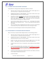
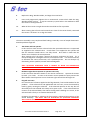
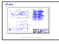
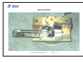
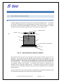
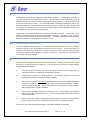
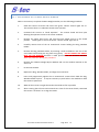
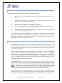
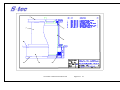
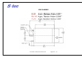
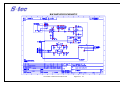
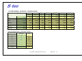
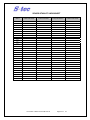
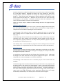
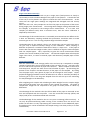
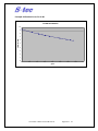
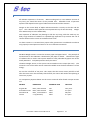
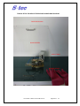
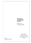
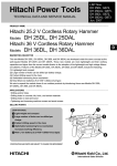
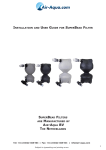
BASIS WEIGHT SENSOR
SERVICE MANUAL
V5.0 October, 2010
Basis Weight Sensor
The Leader in Measurement & Control
TABLE OF CONTENTS
CHAPTER 1 ................................................................................................................................................................................. 4
1.0
BASIS WEIGHT SENSOR SOURCE ............................................................................................................................. 4
1.1 PRINCIPLE OF OPERATION ...................................................................................................................................... 4
1.1.1
RADIOACTIVE MATERIAL ................................................................................................................................... 5
1.1.2
MEASUREMENT OF PAPER ................................................................................................................................ 5
1.2 SOURCE ASSEMBLY ................................................................................................................................................. 5
1.3 SHUTTER OPERATION ............................................................................................................................................. 6
1.4 SAFETY FEATURES ................................................................................................................................................... 6
1.4.1
LOCKING MECHANISM....................................................................................................................................... 6
1.4.2
FIRE SAFETY ....................................................................................................................................................... 7
1.4.3
RADIATION SHIELDING ...................................................................................................................................... 7
1.4.4
ENCAPSULATION................................................................................................................................................ 7
1.4.5
RADIATION WARNING ....................................................................................................................................... 7
1.4.6
MAGNETIC SWITCH ........................................................................................................................................... 7
1.5 FLAG OPERATION ................................................................................................................................................... 8
1.6 AIR CYLINDER OPERATION & ADJUSTMENT ........................................................................................................... 8
1.7 WINDOW REPLACEMENT & CLEANING .................................................................................................................. 8
1.8 TROUBLE SHOOTING ............................................................................................................................................ 10
CHAPTER 2 ............................................................................................................................................................................... 15
2.0
BASIS WEIGHT SENSOR RECEIVER ........................................................................................................................ 15
2.1 PRINCIPLE OF OPERATION .................................................................................................................................... 15
2.2 RECEIVER ASSEMBLY DESIGN DETAIL ................................................................................................................... 16
2.2.1
ION CHAMBER ................................................................................................................................................. 16
2.2.2
SPECIAL OPTICS................................................................................................................................................ 16
2.2.3
AMPLIFIER........................................................................................................................................................ 17
2.2.4
ALUMINIZED MYLAR WINDOW ....................................................................................................................... 17
2.3 WINDOW REPLACEMENT AND CLEANING ............................................................................................................ 17
2.3.1
REPLACEMENT OF THE BASIS WEIGHT WINDOW ............................................................................................ 18
2.4 ION CHAMBER REPLACEMENT ............................................................................................................................. 19
2.5 ELECTROMETER AMPLIFIER DETAILED DESCRIPTION ........................................................................................... 19
2.6 POWER SUPPLY & SIGNALS .................................................................................................................................. 20
2.7 TROUBLESHOOTING ............................................................................................................................................. 21
CHAPTER 3 ............................................................................................................................................................................... 29
3.0
BASIS WEIGHT SENSOR CALIBRATION .................................................................................................................. 29
3.1 CALIBRATION OVERVIEW ..................................................................................................................................... 29
3.2 CALIBRATION ALGORITHMS ................................................................................................................................. 29
3.3 STATIC CALIBRATION ............................................................................................................................................ 31
3.3.1
SENSOR STABILITY CHECK ................................................................................................................................ 31
3.3.2
SAMPLING........................................................................................................................................................ 33
3.4 DYNAMIC CALIBRATION ....................................................................................................................................... 34
CHAPTER 4 ............................................................................................................................................................................... 39
4.0
RADIATION SAFETY ............................................................................................................................................... 39
4.1 ABOUT NUCLEAR RADIATION ............................................................................................................................... 39
4.2 BIOLOGICAL EFFECTS OF RADIATION ................................................................................................................... 40
4.3 RADIOACTIVE MATERIALS USED IN SSS SYSTEMS................................................................................................. 40
4.4 LIMITS FOR EXPOSURE.......................................................................................................................................... 41
4.5 EMERGENCY PROCEDURES ................................................................................................................................... 42
4.6 SAFETY PRECAUTIONS .......................................................................................................................................... 42
4.7 WARNING LIGHTS ................................................................................................................................................. 43
4.8 TRANSPORTATION OF SOURCE............................................................................................................................. 43
4.9 CLEANING AND REPLACING SENSOR WINDOWS .................................................................................................. 43
4.10
SOURCE CAPSULE INFORMATION .................................................................................................................... 44
4.11
INSTALLING OR REMOVING THE SOURCE CAPSULE......................................................................................... 45
CHAPTER 5 ............................................................................................................................................................................... 51
5.0 KEY COMPONENTS ..................................................................................................................................................... 51
The Leader in Measurement & Control
Page 2 of
51
CHAPTER 1:
BASIS WEIGHT SENSOR SOURCE
The Leader in Measurement & Control
Page 3 of
51
CHAPTER 1
1.0
BASIS WEIGHT SENSOR SOURCE
1.1
PRINCIPLE OF OPERATION
The basis Weight Sensor uses the principle of radiation absorption by the paper in order to
measure the paper weight per unit area. The sensor is divided into a Source Assembly
containing the Radioactive Source, and a Receiver Assembly containing the radiation sensing
Ion Chamber and Amplifier. During measurement, radiation is emitted from the source and
some passes through the paper to the Ion Chamber. The heavier the paper, the more
radiation is absorbed by the paper, and the less is measured by the Ion Chamber.
Calibration formulas convert this measured signal into an absolute measurement of Basis
Weight in engineering units.
Kr-85
or
Pm-147
The Leader in Measurement & Control
Page 4 of
51
1.1.1 RADIOACTIVE MATERIAL
The S‐tec Basis Weight Sensor for Tissue and light weight applications uses a 500mCi source
of the isotope Promethium 147 (Pm‐147) as the emitter material. The promethium material
is solid and is contained in a 22mm diameter x 6mm deep .
For S‐tec Basis Weight Sensor for heavier weight applications uses 300mCi source of the
isotope Kr‐85. Krypton is a noble gas and is contained in a small capsule.
Further information about the nature of radioactivity, radioactive isotopes, kinds of radiation
and radiation safety, and capsule specifications can be found later in this manual in the
Radiation Safety Section.
1.1.2 MEASUREMENT OF PAPER
The signal measured by the Ion Chamber approximates to Beer’s Law as follows:
I
=
Io * exp(‐μ*BW)
Where: I
Io
μ
BW
=
=
=
=
Intensity of the signal measuring paper
Intensity of the signal with no paper
Absorption Coefficient
Basis Weight of the Paper
The SSS Basis Weight Sensor uses this principle but adds corrections for Bremsstrahlang
effects (gamma), automatic correction of dirt build‐up, source decay and air density changes.
Most of these are corrected during the sensor standardisation procedure.
1.2
SOURCE ASSEMBLY
Drawings of the Source Assembly are in the appendix to this section. The Source Assembly
consists of a source body inside which can rotate the source holder. The source holder
houses the capsule of radioactive material. When the source is rotated at 90° to the
vertical, no radiation can exit the source so the “shutter” is said to be closed. When the
source holder is rotated so that the source points downwards radiation can exit the source
assembly through a 10mm diameter aperture in the Source Body. The shutter is then said
to be “open”.
During standardise the flag solenoid moves a 20mm diameter piece of Mylar plastic into the
beam to simulate a constant Basis Weight. This is used to correct for any dirt accumulation
since calibration, source activity decay and for window wear or air density effects.
The Leader in Measurement & Control
Page 5 of
51
1.3
SHUTTER OPERATION
Movement of the shutter is controlled by the air pressure in the pneumatic cylinder.
Operation of the cylinder causes the source holder to rotate 90° to the open position by
pushing on the coupling leaver. When air pressure is taken off the pneumatic cylinder the
source holder rotates back to the closed position under the action of the cylinder return
spring.
The source holder rotates on two bearings fitted into the bearing holders.
should never need attention.
These bearing
As the source holder rotates from the closed position, the coupling lever releases the micro
switch so that the Green Radiation Warning Lights go off and the Red Lights come on.
Unless the Green lights are on, the shutter is not fully closed.
The shutter can be locked into the closed position by loosening the lock nut and screwing the
M4 screw in the centre of the Source Body Lid so that it enters the hole for this purpose in
the source holder. For shipping purposes ensure that the screw is tight. In normal
operation the screw should be locked off with the lock nut so that the shutter is free to
move.
1.4
SAFETY FEATURES
The design of the Source Assembly and associated equipment includes the many safety
features below:
1.4.1 LOCKING MECHANISM
When working on the source assembly or in the area of the source assembly, it is advisable
to LOCK the source in the CLOSED position. Locking the source closed is also necessary
during shipping or movement of the source.
The source includes a simple locking mechanism. On the top of the Source Assembly there
is an M4 screw hole in the top of the Source Body Lid. Normally an M4 stainless steel screw
is located in this hole with a locking nut. The nut locks the screw in the raised position
where it does not obstruct the operation of the shutter. To lock the source closed simply
loosen the locking nut and screw the M4 screw as far as it will go with the shutter in the fully
closed position. The screw must extend into the Source Holder Body where a hole is
provided. Locking the nut again will ensure that it cannot come loose. With the screw
fully in place, the source is prevented from rotating and cannot open.
The Leader in Measurement & Control
Page 6 of
51
1.4.2 FIRE SAFETY
In the event of a fire either within the heads or outside, the plastic compressed air tubes
feeding compressed air to the heads and distributing it within the heads, will melt or
rupture. When the compressed air pressure fails, for any reason, the shutter will return to
the closed position automatically. The shutter mechanism is therefore fail‐safe under fire
conditions.
The Source Holder is made from stainless steel, as are the bearing holders. The Source
Body is made from a solid piece of brass. All fasteners are stainless steel. Therefore in
the event of a fire, or even mechanical damage, the source capsule is well protected.
1.4.3 RADIATION SHIELDING
More than adequate radiation shielding in the closed position is provided by the stainless
steel Source Holder and solid Brass Source Body.
In the open position the small gap size (nominally 5‐6mm on tissue applications) and the
structure of the opposing sensor heads, provide excellent shielding. Non‐the‐less it is
advisable that Operators and Engineers ensure that the shutter is properly closed before
working on the heads or cleaning the sensor windows.
1.4.4 ENCAPSULATION
The Pm‐147 material is housed in a Brass capsule with a thin Gold window.
leak proof and is designed to have a working life of up to 5 years.
The capsule is
1.4.5 RADIATION WARNING
On the Source Assembly is located a micro switch to control the radiation warning lights.
Only when the shutter is fully in the closed position will the Red lights go out and the Green
lights come on. Radiation warning lights are located on each side of both the upper and
lower heads. The lights are LEDs so should never need to be replaced. External warning
lights on the end of the scanner are also be installed.
It is required that radiation warning labels be placed on the scanner outlining the type of
radioactive material and activity.
1.4.6 MAGNETIC SWITCH
The Leader in Measurement & Control
Page 7 of
51
For additional Operator and Engineer safety, a magnetic reed switch is installed in the circuit
of the shutter solenoid. The reed switch is in the lower head and closes when the magnet
on the corresponding upper head is close. This simple device ensures that the shutter
cannot open unless the heads are very close together. Should he heads separate, for any
reason, then a potential radiation hazard would exist if the shutter should open. This is
because the lower head may not be present to act as a shield. When the heads are
displaced by more than about 30mm, the reed switch opens and the solenoid valve releases,
closing the shutter.
1 .5
FLAG OPERATION
The Flag is inserted by energising the 24V dc solenoid mounted on the Source Mounting
Plate. The solenoid rotates the flag assembly so that the Mylar sample is centred in the
radiation beam when the shutter is open.
The flag should normally never need adjustment. The clearance between the flag and the
Source Body and to the Source Front Ring is very tight. Should it be necessary to adjust the
flag, care should be taken to ensure the flag does not bind during the movement. Also
ensure that the flag Mylar sample is exactly centred in the beam when the solenoid is fully
energised.
1.6
AIR CYLINDER OPERATION & ADJUSTMENT
A miniature stainless steel air cylinder operates the shutter mechanism. Compressed air to
the air cylinder is switched from the solenoid valve. The solenoid valve is a 3‐port valve
which either supplies compressed air to the cylinder at the full line pressure or vents the
cylinder to atmosphere. In either case the air flows to the cylinder to operate it or from the
cylinder when releasing. Flow is restricted by the miniature needle valve. It is important to
adjust the needle valves for a slope operation and release of the cylinder.
The purpose of the miniature needle valve, located on the cylinder entry, is to control the
rate of operation and release. The valve is adjusted so that the cylinder operates slowly
and releases slowly, therefore extending the life of the cylinder and source components. If
the cylinder releases too quickly the shutter warning lights can be seen to flicker as the
shutter “bounces”.
1.7
WINDOW REPLACEMENT & CLEANING
The Basis Weight Sensor window is an aluminized Mylar film (Pm‐147) or Antistatic Heavy
Film (Kr‐85). The window provides a barrier to dirt, dust and hot or humid air into the
sensor. At the same time it is sufficiently low density to allow most of the beta particles
from the source to pass through. The Source window and the Receiver window are
identical.
It is important to regularly inspect and clean the window. Cleaning of the window should
be done on a daily basis by the Operator.
The Leader in Measurement & Control
Page 8 of
51
1.7.1 CLEANING THE BASIS WEIGHT WINDOWS
The procedure for cleaning the Basis Weight Mylar windows is as follows:
1.
Send the scanner off sheet and ensure the green “shutter closed” lights are on.
This ensures there is no radiation hazard to the operator.
2.
Command the scanner to “Head Separate”. The scanner heads will then split
allowing the Operator access to the sensor windows.
3.
Using water or alcohol, very gently wipe the surface of the Basis Weight window to
remove dirt and dust.
Both the upper, Receiver side, window and the lower,
Source side, window should be cleaned. At the same time clean the Moisture
Sensor windows and the edge sensor sapphire windows.
4.
Inspect the basis weight window for any holes or cuts. Any damage to the window
might result in dirt entering the sensor. In this case the window should be replaced
immediately.
5.
After all cleaning has been completed make sure there are no tools or materials left
on the heads, then press the “Off Sheet” button to close and align the heads.
In the event of any window damage the window should replaced be immediately.
1.7.2 REPLACEMENT OF THE BASIS WEIGHT WINDOW
When it is necessary to replace the Basis Weight window, use the following procedure:
1.
Send the scanner off sheet and ensure the green “shutter closed” lights are on.
This ensures there is no radiation hazard to the operator.
2.
Command the scanner to “Head Separate”. The scanner heads will then split
allowing the Operator access to the sensor windows.
3.
Remove the lower head cover and lock the basis weight source in the closed
position. Check again to ensure the Green “shutter closed” lights are on.
4
Carefully remove each of the 16 countersunk screws holding the Ring, Window
Holder.
5.
Remove the Ring, Window Holder, by inserting a small screwdriver into one of the
screw holes and levering the ring loose very gently. DO NOT INSERT ANY OBJECT
INTO THE BW WINDOW because it could puncture the Ion Chamber Window or
damage the source capsule. Wear safety glasses while performing this procedure.
6.
Remove the old Basis Weight Mylar Window and install a new window, if necessary
cut the window material to the correct size.
7.
Fit the new window.
The Leader in Measurement & Control
Page 9 of
51
1.8
8.
Replace the Ring, Window Holder, and align the screw holes.
9.
Insert and progressively tighten the 16 countersunk screws which hold the Ring,
Window Holder in place. It may be necessary to prick holes in the window to allow
the screws to easily penetrate.
10.
When all the screws are tight the window should be as flat as possible.
11.
After ensuring that all tools and materials are clear of the sensor heads, command
the scanner “off sheet” to re‐align the heads.
TROUBLE SHOOTING
The source assembly is very simple and fault finding is normally a case of simple observation.
Possible problems might be:
1.
The shutter will not operate.
In this case first check that the solenoid valve has operated and there is compressed
air supplied to the solenoid valve. Check there is air supplied to the cylinder and
that the miniature needle valve is not fully closed. Also check to make sure the
shutter is not locked in the closed position.
After checking all of the above, operate the shutter mechanism by hand. If it is
clearly binding then investigate the source mechanism itself. If it seems necessary
to dismantle the source mechanism, call a qualified person. Do not attempt any
dismantling unless qualified, trained and knowledgeable.
ONLY QUALIFIED PERSONNEL WITH A LICENSE TO WORK ON RADIOACTIVE
DEVICES MAY DISMANTLE THE SOURCE MECHANISM.
2.
Radiation Lights do not operate or operate incorrectly
In this case check the Micro Switch on the source mechanism. Operate the shutter
by hand ‐ just a little. As soon as the shutter moves towards the open position the
Micro Switch should operate to turn the Green Lights off and the Red Lights on.
3.
Flag will not insert
First check that a full 24V is applied to the flag solenoid, if not look elsewhere for the
problem. If the solenoid has 24V applied but will not insert, move the solenoid by
hand by gently rotating the solenoid. If the solenoid operates in this way but not
electrically then the solenoid coil is likely to be open circuit. If the solenoid will not
rotate or if the solenoid binds, then either the flag itself is binding as it moves, or the
solenoid itself is faulty or is contaminated with dirt.
Changing the solenoid or adjusting the flag involves substantial dismantling of the
source assembly. THIS MUST ONLY BE ATTEMPTED BY QUALIFIED PERSONNEL
WITH PROPER TRAINING.
RADIATION HAZARD!
The Leader in Measurement & Control
Page 10 of
51
The Leader in Measurement & Control
Page 11 of
51
SOURCE ASSEMBLY
The Leader in Measurement & Control
Page 12 of
51
PICTURE SHOWING BASIS WEIGHT SOURCE ASSEMBLY INSTALLED IN HEAD
The Leader in Measurement & Control
Page 13 of
51
CHAPTER 2:
BASIS WEIGHT SENSOR RECEIVER
The Leader in Measurement & Control
Page 14 of
51
CHAPTER 2
2.0
BASIS WEIGHT SENSOR RECEIVER
2.1
PRINCIPLE OF OPERATION
The Basis Weight Sensor Receiver is the active part of the Basis Weight Sensor. It measures
the amount of radiation that has passed through the paper from the source. This signal is
then used to compute the Basis Weight of the paper. The receiver assembly is normally
located in the lower enclosure head, the source is normally in the upper head.
Amplifier Shield
Amplifier
PCB
Stainless Steel Window
FIG 2.1
BASIS WEIGHT RECEIVER SCHEMATIC
Beta particles from the source pass through the source Mylar window, where some are
absorbed. The remainder pass through the paper where they are absorbed at a rate
depending primarily on the sheet mass, then through the receiver Mylar window, optics and
to the ion chamber. Particles are also absorbed by the air column mass that the particles
must travel through. Once reaching the Ion Chamber the particles must then penetrate the
Ion Chamber titanium steel window. The particles that succeed in entering the Ion
Chamber cause the argon gas inside to ionise. Ionisation of the gas will result in a minute
current flow to the operational amplifier. This current flow is proportional to the radiation
energy received.
The very small current from the Ion Chamber is amplified by the Operational Amplifier circuit
on the PCB and converted to a 0 to 2mA current output to the ADC.
The Leader in Measurement & Control
Page 15 of
51
2.2
RECEIVER ASSEMBLY DESIGN DETAIL
The Basis Weight Sensor is designed to measure the basis weight of the paper very
accurately. To do this it needs to be very stable, rugged, insensitive to flutter & ash, and be
able to be re‐calibrated on‐line automatically (standardisation), to correct for source decay
and environmental changes. A detailed description of the Basis Weight Sensor Receiver
would describe the following components:
2.2.1 ION CHAMBER
The Ion Chamber is a sealed aluminium cylinder with an insulated electrode inside. Inside
the cylinder is Argon gas at a pressure of 1520 Torr. A window of 25 micron (0.001 inch)
stainless steel allows the radiation to enter the chamber while retaining the pressurised
Argon gas. Beta particles entering the ion chamber collide with the Argon gas molecules
causing ionisation.
The Ion Chamber is mounted inside the aluminium sensor enclosure and insulated from it
with Delron rings. The body of the Ion Chamber is connected to the ‐400V dc supply.
Positively charged ions created by the beta particle collisions with the Argon gas, migrate to
the body attracted by the ‐400V potential. The Negatively charged ions are attracted to the
Ion Chamber electrode, which is at virtual ground potential (+400V relative to the body), and
create the small current to the amplifier. The current is proportional to the beta particle
energy entering the ion chamber.
The Ion Chamber window surface should be tight due to the pressure of Argon inside. If
gas leaks from the chamber, the window may become slack and crinkled looking. The Ion
Chamber cannot be repaired and must be replaced if damaged or if the gas leaks. Avoid
touching the Ion Chamber window because a rupturing of the Ion Chamber Window could be
a hazard to the eyes due to the pressure of Argon inside.
2.2.2 SPECIAL OPTICS
The purpose of the optics is to eliminate the sensitivity of the sensor to sheet flutter and to
ash content in the paper. Flutter sensitivity means the sensitivity to the position of the
sheet in the gap. The optic parts are of a proprietary nature and depend on the
application.
The optics is located beneath the sensor Mylar window and immediately before the Ion
Chamber. The optics includes the source window material. All beta particles must pass
through the optics before they can enter the Ion Chamber.
The Leader in Measurement & Control
Page 16 of
51
2.2.3 AMPLIFIER
The Amplifier PCB contains a high gain electrometer amplifier. The amplifier circuit has a
very high impedance and 10mS time constant. Gain is selected, with appropriate choice of
feedback resistor, to achieve an output signal to the ADC of between 6 ‐ 8V at the ADC, with
the shutter open and no paper. Care should be taken if changing the amplifier gain to not
exceed 9V output for a clean sensor with no paper in the gap. More than this may overload
the input of the ADC and result in a non‐linear output signal. A more detailed description of
the amplifier circuit is given later in this section.
The printed circuit board is made of 2 separate printed circuit boards. The smaller, inner,
board is mounted directly on to the Ion Chamber electrode. The larger, outer, board is
mounted on the top of the receiver assembly body. A stainless plate protects the amplifier
board and provides a shield against electrostatic noise.
2.2.4 ALUMINIZED MYLAR WINDOW
The Basis Weight Sensor window is a conductive aluminized mylar film. The window
provides a barrier to dirt, dust and hot or humid air into the sensor. At the same time it is
sufficiently low density to allow most of the beta particles from the source to pass through.
The Source window and the Receiver window are identical. Cleaning and replacement of
the window is described below.
2.3
WINDOW REPLACEMENT AND CLEANING
It is important to regularly inspect and clean the window. Cleaning of the window should
be done on a daily basis by the Operator. The procedure for cleaning the Basis Weight
Mylar windows is as follows:
1.
Send the scanner off sheet and ensure the green “shutter closed” lights are on.
This ensures there is no radiation hazard to the operator.
2.
Command the scanner to “Head Separate”. The scanner heads will then split
allowing the Operator access to the sensor windows.
3.
Using water or alcohol, very gently wipe the surface of the Basis Weight window to
remove dirt and dust.
Both the upper, Source, window and the lower, Receiver,
window should be cleaned. At the same time clean the Moisture Sensor windows
and the edge sensor sapphire windows.
4.
Inspect the basis weight window for any holes or cuts. Any damage to the window
might result in dirt entering the sensor. In this case the window should be replaced
as soon as possible.
5.
After all cleaning has been completed make sure there are no tools or materials left
on the heads, then press the “Off Sheet” button to close and align the heads.
In the event of the window being damaged, it should be immediately replaced.
The Leader in Measurement & Control
Page 17 of
51
2.3.1 REPLACEMENT OF THE BASIS WEIGHT WINDOW
When it is necessary to replace the Basis Weight window, use the following procedure:
1.
Send the scanner off sheet and ensure the green “shutter closed” lights are on.
This ensures there is no radiation hazard to the operator.
2.
Command the scanner to “Head Separate”. The scanner heads will then split
allowing the Operator access to the sensor windows.
3.
Remove the upper head cover and lock the basis weight source in the closed
position. Check again to ensure the Green “shutter closed” lights are on.
4
Carefully remove each of the 16 countersunk screws holding the Ring, Window
Holder.
5.
Remove the Ring, Window Holder, by inserting a small screwdriver into one of the
screw holes and levering the ring loose very gently. DO NOT INSERT ANY OBJECT
INTO THE BW WINDOW because it could puncture the Ion Chamber Window.
Wear eye protection during this procedure.
6.
Remove the old Basis Weight Mylar Window and cut the window material to the
same size.
7.
Fit the new window.
8.
Replace the Ring, Window Holder, and align the screw holes.
9.
Insert and progressively tighten the 16 countersunk screws which hold the Ring,
Window Holder in place. It may be necessary to prick holes in the window to allow
the screws to penetrate.
10.
When all the screws are tight the window should be as flat as possible.
11.
After ensuring that all tools and materials are clear of the sensor heads, command
the scanner “off sheet” to re‐align the heads.
The Leader in Measurement & Control
Page 18 of
51
2.4
ION CHAMBER REPLACEMENT
Changing the Ion Chamber is straight forward.
Proceed as follows:
1.
Remove the Receiver Assembly from the heads and take to a work bench in a clean
area.
2.
Remove the PCB assembly, taking great care when removing the centre screw
connection to the ion chamber electrode.
3.
Remove the “Plate, Retainer, Ion Chamber” cover plate.
4.
Lift the Ion Chamber out of the assembly and replace with the new Ion Chamber.
5.
Reassemble in the reverse order the above.
screw on the Ion Chamber electrode.
Take care not to over tighten the
Care should be used when handling the Ion Chamber to ensure that the thin titanium
window is not damaged. Avoid touching the window and never allow any tools or other
sharp objects to go near to the window. Rupture of the window with the pressure of the
Argon gas, could present a danger to the eyes.
2.5
ELECTROMETER AMPLIFIER DETAILED DESCRIPTION
The Electrometer Amplifier consists of 2 printed circuit board, one inside the other. The
smaller board is connected directly on to the centre electrode of the Ion Chamber. R2
resistor (10MΩ) on this board along with C1 (100PF) provides the 10ms time constant
smoothing for the signal.
The main board contains all the active elements of the amplifier. U1 is the electrometer
amplifier, AD549, which amplifies the very small signal from the Ion Chamber. The gain of
this amplifier is determined by the feedback resistor R1. R1 is selected at installation in
order to make the output current to the ADC about 1.6mA (approx. 8V across the ADC
input). The signal will fall over time as the source decays, however adjustment of the
feedback resistor is not usually necessary.
A null adjustment is provided so that when the shutter is closed the amplifier signal is
close to zero. Because it is better to avoid the possibility of a negative voltage to the ADC
the null potentiometer should be adjusted to provide a slight positive signal with the shutter
closed. When measured by the computer, the offset voltage should be between 20 and
100mV. The system measures these “background counts” during a periodic “background
count check” procedure and subtracts them from all open shutter measurements.
U2 is a dual OP‐270Z Operational Amplifier. The first half of the IC, U2‐A, acts as a buffer
amplifier of unity gain. This feeds the second half of the IC which is a Voltage to Current
output driver. The input voltage to the driver, U2‐B, is a 0 to 4V dc signal. Output is a 0 to
The Leader in Measurement & Control
Page 19 of
51
2mA current signal to the ADC channel. The ADC input has a 5KΩ resistor which converts
the 0 to 2mA signal into 0 to 10V. Because the computer calculates the Basis Weight of the
paper from the ratio of the open and the on‐sheet signals, the absolute value of the signal is
unimportant provided the signals never saturate and are in reasonable range.
2.6
POWER SUPPLY & SIGNALS
The Receiver Assembly requires +12V, ‐12V and ‐400V power and provides a 0 to 2mA
output signal. Facility exists on the board for a high voltage DC/DC converter to provide the
‐400V power, this is only used for a fixed point, stand alone, Basis Weight Sensor application.
The pin connections for the power and signals are:
J1 ‐ 1
J1 ‐ 2
J1 ‐ 3
J1 ‐ 4
J1 ‐ 5
J1 ‐ 6
J1 ‐ 7
J1 ‐ 8
J1 ‐ 9
J1 ‐ 10
N/C
N/C
GND
+12VDC
‐12VDC
GND
GND
N/C
GND
‐400VDC
J2 ‐ 1
J2 ‐ 2
Signal Output, 0 to 2mA
Signal Return to Ground
The Leader in Measurement & Control
Page 20 of
51
2.7
TROUBLESHOOTING
Most of the problems with Basis Weight Receiver would be:
1.
No Signal
If there is no Basis Weight signal then check the following:
a)
b)
c)
d)
Is the shutter open? The signal will only be present if there is radiation to be
measured. Physically check the source assembly to make sure the shutter is really
in the fully open position. Do not rely just on the shutter lights.
Are the supply voltages correct for the Basis Weight Sensor? The sensor needs
+12V, ‐12V, ‐400V & Ground.
Are the connectors properly on?
Is there a signal to the ADC? If yes, then the problem is elsewhere.
The above are the most likely causes. Check them before doing anything else. After this
the only possible causes are with the Ion Chamber itself or with the amplifier PCB.
2.
Too Small a Signal
f)
g)
If the signal is too small and the problem happened suddenly (i.e. not due to normal
source decay over years), then check the following:
Is the shutter opening fully? Any obstruction in the radiation path, including the
shutter not opening fully, will cause a reduced signal.
Are the
Is there anything in the gap ‐ such as a piece of paper or excessive dirt?
windows damaged allowing dirt or water to get into the sensor?
Check the supply voltages, especially the ‐400V supply. Are they correct?
Is the Flag stuck in or is it loose? Is the flag operating correctly?
Check the signal at the ADC. If OK at the ADC, (up to 10V with no paper) then the
problem is elsewhere.
Faulty Ion Chamber.
Faulty amplifier
3.
Noise
a)
b)
c)
d)
e)
a)
b)
c)
d)
e)
A noisy signal could be:
Some object in the paper path that is moving e.g. paper, loose flag, broken window,
shutter movement, low compressed air pressure (shutter moving).
Water entering the sensor or on the window.
An Ion Chamber that has leaked gas (is the window still "tight").
Loose connections ‐ check all, including the connections to the Ion Chamber
Faulty amplifier.
Check if the noise is coming from the sensor or elsewhere, such as ADC or Computer.
The Leader in Measurement & Control
Page 21 of
51
The Leader in Measurement & Control
Page 22 of
51
PICTURE SHOWING BASIS WEIGHT RECEIVER INSTALLED
The Leader in Measurement & Control
Page 23 of
51
ION CHAMBER
The Leader in Measurement & Control
Page 24 of
51
BW AMPLIFIER SCHEMATIC
The Leader in Measurement & Control
Page 25 of
51
VOLTAGE DIVIDER
RESISTORS - GAIN MULTIPLIER
R7
R5
R7-1
R7-2
R7-3
1
2
4
R7-1/2
R7-1/3
R7-2/3
R7-1/2/3
0.67
0.80
1.33
0.57
R5-1
10.00
10.00
5.00
2.50
15.00
12.50
7.50
17.50
R5-2
15.00
15.00
7.50
3.75
22.50
18.75
11.25
26.25
R5-3
20.00
20.00
10.00
5.00
30.00
25.00
15.00
35.00
R5-1/2
6.00
6.00
3.00
1.50
9.00
7.50
4.50
10.50
R5-1/3
6.67
6.67
3.33
1.67
10.00
8.33
5.00
11.67
R5-2/3
8.57
8.57
4.29
2.14
12.86
10.71
6.43
15.00
R5-1/2/3
4.62
4.62
2.31
1.15
6.92
5.77
3.46
8.08
MAIN F/B RESISTORS - GAIN MULTIPLIER
RES KΩ
GAIN
1
100
3.0
2
100
3.0
3
100
3.0
1+2
50
1.5
1+3
50
1.5
2+3
50
1.5
1+2+3
33
1.0
The Leader in Measurement & Control
Page 26 of
51
BASIS WEIGHT SENSOR AMPLIFIER PCB ‐ LAYOUT
The Leader in Measurement & Control
Page 27 of
51
CHAPTER 3:
BASIS WEIGHT SENSOR CALIBRATION
The Leader in Measurement & Control
Page 28 of
51
CHAPTER 3
3.0
BASIS WEIGHT SENSOR CALIBRATION
3.1
CALIBRATION OVERVIEW
The Basis Weight Sensor is capable of very accurate measurement of the basis weight of
paper as it is being made on a paper machine. The Sensor itself, together with the
ADC, provides an input to the computer. The voltage is a measurement of the radiation
being received. From this signal the computer must calculate the basis weight of the
paper, fully compensating for dirt build‐up, air density changes, radioactive source
decay, electronic drift etc.. To achieve this, the computer is programmed with
proprietary calibration algorithms.
3.2
CALIBRATION ALGORITHMS
The following algorithms are proprietary and must not be disclosed to others.
Algorithms are programmed into the computer.
I
Io
I1
I2
I3
aIo
BWo
BW
FW
(1)
(2)
on-sheet signal (profile corrected)
clean gauge open signal (calculated)
open gauge signal (actual)
flag signal
background signal
bremsstrahlang correction
dirt weight
basis weight
flag weight
dirt and flag readings can be modelled over narrow ranges:
BWo = 1 ln Io
μ1
I1
BWo + FW = 1 ln Io
- W
μ2
I2
where μ1, μ2 and W are parameters
The Leader in Measurement & Control
Page 29 of
51
These
Standardise (Stdz):
BWo & Io can be calculated from (1) and (2) at Stdz:
(3)
BWo =
(4)
Io
1
[ln (I1) - μ2(FW +W)]
-μ2-μ1
(I2)
μ
= I1e 1BWo
On Sheet:
(5)
X = Io - aIo - I3
I - aIo - I3
where a is a calibration parameter
(6)
BW =
AlnX - BWo
1 + (B)
(X)
where A and B are calibration parameters
Dynamic Standardisation:
Dynamic standardisation corrects for dirt build-up between full standardisations. This
is done by assuming that Io stay unchanged between standardisation and by measuring I1
(profile corrected) while the scanner turns around outside the sheet.
(7)
BWo = 1
ln(Io)
μ1
(I1)
The Leader in Measurement & Control
Page 30 of
51
3.3
STATIC CALIBRATION
Static Calibration of the sensor is normally carried out using Mylar or Aluminised Mylar
samples of know basis weight. A range of Mylar samples covering the total basis range
of paper is required.
The procedure for static calibration should be broken down into the following steps:
1.
Sensor stability check.
2.
Sampling.
3.
Calculation of the calibration constants.
4.
Recheck of calibration
A description of each of these steps is below.
3.3.1 SENSOR STABILITY CHECK
Before starting the calibration procedure it is important to ensure that the sensor is
stable. Any problems with stability should be resolved before proceeding. Stability
of the sensor means that the sensor gives repeatable and consistent readings for the
same conditions.
The stability check is performed by doing a total of 30 successive standardise checks.
The standardization is commanded from the video screen. The results should be
tabulated in the form below:
The variation of the counts above should not change by more than about 10mV
Standard Deviation (Sigma) for the Open and Flag signals. For the Closed signal this
should not have varied by more than about 5mV.
The Leader in Measurement & Control
Page 31 of
51
SENSOR STABILITY WORKSHEET
STZ #
OPEN VOLTAGE
FLAG VOLTAGE
FLAG/AIR RATIO
CLOSED VOLTAGE
1
2
3
4
5
6
7
8
9
10
11
12
13
14
15
16
17
18
19
20
21
22
23
24
25
26
27
28
29
30
The Leader in Measurement & Control
Page 32 of
51
3.3.2 SAMPLING
Insert each of the Mylar samples into the gap using the sample holder to ensure exact
registration. For each sample do 5 sample checks and note the voltage for each
sample check. The sample check is commanded from the video screen.
Record the results of the sampling as shown in the table below:
SAMPLE # SAMPLE 1
VOLTAGE
Sample1
GSM
Sample 2
GSM:
Sample 3
GSM
Sample 4
GSM
Sample 5
GSM
SAMPLE 2
VOLTAGE
SAMPLE 3
VOLTAGE
SAMPLE 4
VOLTAGE
SAMPLE 5
VOLTAGE
AVERAGE
VOLTAGE
Next tape a fixed piece of very light Mylar or other film material of accurately known
basis weight over the sensor lower window. This is to simulate an accumulated
amount of dirt of known weight. The sensor Open Voltage and Flag Voltage are
measured with the “dirt” in place. These voltages will therefore be lower than those
without the dirt.
STZ with
Dirt
Open
Volts
Flag Volts
Actual
Dirt Wt
Sample 4
GSM
Sample 5
GSM
STZ
1
STZ
2
STZ
3
STZ
4
STDZ
5
AVERAGE
VOLTAGE
When all the results of the static sampling have been tabulated, fax these and the
stability check results to SSS. SSS engineers will use a computer program to fit the best
calibration curve through the data and calculate the optimum calibration constants.
This same procedure is used in‐house to calibrate the Basis Weight Sensors before
shipment.
The Leader in Measurement & Control
Page 33 of
51
3.4
DYNAMIC CALIBRATION
Dynamic calibration is needed to make the sensor read the correct value of real paper
on a real paper machine. Although the sensor may very accurate on static (non‐
moving) samples, machine conditions can change the calibration depending on such
things as: sheet furnish; sheet temperature; moisture gain/loss; sheet stretch under
tension, environmental effects etc. Whatever the source of the error when measuring
moving paper on the machine, a method is needed to check the calibration of the
sensor and make suitable corrections to the calibration.
There are 4 major ways to calibrate the Basis Weight Sensor on the paper machine.
These are:
Calibrate to Mill Laboratory
This method simply compares the sensor end of reel Basis Weight measurement with
that of the Mill laboratory result. To do this well, it is essential that a large number of
comparisons are made before adjusting the sensor calibration.
The advantage of this method, which is useful for getting the sensor to correct “ball
park” reading, is that it is simple and the sensor reads similar values to that of the
laboratory.
The disadvantage of this method is that the laboratory result is often noisy, can have a
systematic error, often changes as the laboratory person changes at each shift, and
most importantly, proper precautions are rarely taken by laboratory people to protect
the samples from moisture gain or loss.
This method, then, is recommended only to get the sensor reading close to the correct
value or where it is a requirement that the sensor measure the same as the laboratory.
Roll Weight Check
The SSS system measures the length of paper made during a reel and also the width.
From this data and from the measured average Basis Weight, the computer calculates
the weight of the paper on the reel.
It is possible to accurately weigh the roll of paper after the change of reel. Subtracting
the weight of the steel shell from this will give the weight of the paper. This can be
compared to the measured weight to calculate the difference.
The advantage of this method is that it is relatively easy to do if accurate scales are
available.
The disadvantage of this method is that the accuracy of the scales is very important and
the paper weight is the result of two measurement ‐ paper + steel shell, and steel shell
without paper. The overall accuracy also depends on an accurate width measurement
and an accurate tachometer measurement of the reel speed. Another disadvantage is
that when measuring paper grades that contract when no longer under tension (such as
crepe tissue), the weight calculated is often significantly different from the weight
measured by the laboratory of a relaxed, and so contracted, sheet of paper.
The Leader in Measurement & Control
Page 34 of
51
Single Point Measurement(s)
In this method the scanner heads are put in single point (fixed position on sheet) to
continuously measure the Basis Weight of the paper in that position. Towards the end
of the reel, a card is placed in the paper to indicate the start of measurement. At the
same time the single point readings are integrated and averaged until reel turn‐up
occurs.
When the reel is out, many samples are cut from the paper in the position of the sensor
during single point measurement. The average Basis Weight reading calculated from
the samples, is compared to the average sensor measurement. If 3 or more such
samples (on different reels) show a consistent error, then the sensor calibration is
adjusted by this amount.
The advantage of this method is that it is reasonably accurate and not too difficult to do.
It does use laboratory sampling methods but precautions should be taken to avoid
moisture gain or loss ‐ such as using polythene bags to hold the samples.
The disadvantage of this method is that it can sample only one spot each time and so
can give only a required intercept change to the calibration. More sampling in
different CD positions is needed to determine if there is a slope error. If the paper is
uneven with narrow basis weight streaks, then it is difficult to align the measured paper
with the sampled paper. This is especially so given the narrow measurement beam
(10mm at the source window) of the sensor. The manual samples taken will always be
larger than 10mm, so sensor measured paper and laboratory sampled paper will be
different.
CD Sampling Method
With this method the trend average profile at the reel turn‐up is compared to multiple
samples of paper taken across the full width of the reel after turn‐up. One way to do
this is to slab off the top 25mm of paper onto the floor. With a template of know area
and sharp knife, samples are taken across the full width of paper. By alternating the
position of the sample in the MD direction, all the paper can be sampled. By cutting
into the paper layers, many pieces of paper can be averaged in each sample. Proper
polythene bagging procedures need to be adhered to in order to avoid the possibility of
moisture gain or loss in the long time elapsed from the reel turn‐up to the measuring
the sample weights in the laboratory.
After weighting each sample and calculating the Basis Weight from the sample weight
(less bag) and the paper area, the results of each sample are graphed. The graph of
sample basis weight can be compared to the graph of sensor profile to show any
differences.
The advantage of this method is that the full CD width of the paper is measured at one
time and compared with the CD profile. From this result both intercept (offset) and
slope (scale) errors can be determined and corrected.
The disadvantage of this method is that it is very time consuming (allow one hour). It
can only be performed during stable running of the machine when the end of reel
profile can be taken as truly representing the measurement of the slabbed‐off paper.
A significant error can be introduced if the sample cutting is not done perfect, or is done
inconsistently.
The Leader in Measurement & Control
Page 35 of
51
Example Calibration Curve for Kr‐85
Kr-85 BW Calibration
10
9
8
Signal Voltage
7
6
5
4
3
2
1
0
0
20
40
60
80
100
120
140
g/m2
The Leader in Measurement & Control
Page 36 of
51
160
Example Calibration Curve for Pm‐147
BW / VOLTS
6
5
Volts
4
3
2
1
0
0
10
20
30
40
50
60
40
50
60
Page 37 of
51
BW GSM
After Linearization
BW / LN X
1.2
1
LN X
0.8
0.6
0.4
0.2
0
0
10
20
30
BW GSM
The Leader in Measurement & Control
CHAPTER 4:
RADIATION SAFETY
The Leader in Measurement & Control
Page 38 of
51
CHAPTER 4
4.0
RADIATION SAFETY
4.1
ABOUT NUCLEAR RADIATION
Radioactive atoms give off ionising radiation in
the form of fast‐flying particles or as rays.
Some of these particles are called Alpha
Particles. They travel only a few centimetres in
air and have little or no penetrating power.
Alpha particles are fast moving Protons.
Other particles are called Beta Particles. They travel about one meter or so in air but
will not penetrate much beyond the depth of a person’s skin. Beta particles are fast
moving electrons.
Still stronger radiation, in the form of electromagnetic rays, is Gamma Rays. They
travel at the speed of light. An only dense material with a high atomic number such as
lead is effective in stopping them. Gamma rays are the same as X‐rays except that they
are generated in the atom rather than in an X‐ray tube.
Note: The SSS Basis Weight Sensor uses Beta radiation.
The Leader in Measurement & Control
Page 39 of
51
4.2
BIOLOGICAL EFFECTS OF RADIATION
All radiation exposure is of concern. When working with or near radiation sources of
any kind, you should be aware of the possible risks. Allowable levels of personal
exposure will depend on the type of radioactive material and the situation.
Danger to the human body of Alpha and Beta Particles is mostly to the skin and the
eyes. This is because these particles cannot penetrate very far into the body. Danger
from Gamma Rays is to the whole body.
Over exposure of radiation may damage or kill the tiny living cells that make up our
body. Large amounts of radiation or repeated high exposures may increase the risk of
serious disease such as cancer or leukaemia later in life.
For these reasons it is essential that proper safety precautions are adhered to and that
only properly trained personnel work on or near radioactive materials.
4.3
RADIOACTIVE MATERIALS USED IN SSS SYSTEMS
SSS Basis Weight sensors are used to measure paper and paper board. The principle of
measurement is that radiation is absorbed by the paper or board. Therefore the type
of radiation that is used in SSS systems MUST be easily absorbed by paper but not be
totally absorbed. Only Beta particles satisfy this need.
The Basis Weight sensor in this system uses Promethium 147 isotope (Pm‐147). This
material is one of the safest source materials available since the beta radiation is of low
energy.
Pm‐147 has a half life of 2.6 years. This means that the source activity will fall to half
after this time. Given this relatively short half life, the source will need to be replacing at
least every 5 years.
For comparison purposes below are the source materials often found in Paper Sensors
are:
SOURCE
RADIATION
MATERIAL TYPE
HALF LIFE
Krypton 85
Promethium 147
Strontium 90
Iron 55
Beta, some Gamma
Beta, some Gamma
Beta , some Gamma
x‐ray (Gamma)
Gas
Solid
Solid
Solid
10.7 years
2.6 years
28 years
2.7 years
The Leader in Measurement & Control
Page 40 of
51
4.4
LIMITS FOR EXPOSURE
The quantity of ionising radiation exposure is measured in terms of ionisation called
roentgens but may also be measured in terms of energy absorbed called Rads or Rems.
R = Roentgen This the special unit of exposure.
air under standard conditions.
2.58 x 10‐4 Coulomb per kilogram of
Rad
Unit of absorbed dose is the energy imparted to matter (such as human
tissue) by ionising radiation per unit mass of irradiated material at the
place of interest. For X‐rays or Gamma Rays, 1 R (Roentgen) of
exposure will produce about 1 Rad of absorbed dose in soft tissue.
Gy = (Gray)
The SI unit of absorbed dose.
Rem
Stands for “Roentgen Equivalent Man”. A special unit of dose
equivalent. The dose equivalent in Rems is numerically equal to the
absorbed dose in Rads multiplied by a factor weighted for relative
biological effect on the tissue being exposed. For routine protection
calculations of exposure to x‐rays, 1R = 1 Rad = 1 Rem.
1 Rad = 0.01 Gy
Sv = (Sievent) The SI unit dose equivalent to 1 Rm = 0.01 Sv
DOSE LIMITS
All radiation is of concern. When working around sources of radiation you should be
aware of the possible risks. Allowable levels of personal exposure will vary depending
on the situation. Limit of exposure are established in each country. Typical dose
limits are:
Maximum Yearly dose:
Occupationally exposed ‐ whole body
Skin or any extremities
Eyes
Dose to Embryo / Foetus
Public or Non‐occupationally Exposed
The Leader in Measurement & Control
REM
5
50
15
0.5
0.1
mSv
50
500
150
5
1
Page 41 of
51
4.5
EMERGENCY PROCEDURES
In the event of an emergency such as a serious fire affecting the source enclosure, or if
the red shutter light stays on and cannot be made to go off, do the following:
1.
Send the scanner off sheet.
2.
Keep unauthorized personnel away from the scanner heads.
of about 3 Metres for safety.
3.
Immediately inform the site radiation safety officer or SSS trained engineer.
Keep a distance
The trained engineer or safety officer will investigate the problem and determine if any
risk exists. In the case of a shutter not closing properly he may be able to rectify the
problem without any exposure risk to himself or others.
If there is evidence of possible damage to the source capsule then the action taken will
depend on the type of source material. For Promethium 147 a wipe test must be done
and the resulting swab tested for any sign of radioactive material leakage using a
radiation survey meter.
4.6
SAFETY PRECAUTIONS
It is essential that all personnel who work on or near a radiation source take sensible
safety precautions to minimise any exposure to radiation.
Because the source material in SSS sensors emits mostly Beta radiation which cannot
penetrate more than a little over one meter of air, avoiding risk of exposure can be done
in 3 ways:
Shielding ‐ ensure that the shutter is closed and the green light is on, before working on
the heads or the sensor.
Distance ‐ keep a distance from the source. Beta radiation cannot penetrate far in air
(about 1.5M) so maximise the distance between any part of the body and the source.
Time ‐ Minimise the time near to the source.
time is spent in an exposed condition.
Any exposure is halved if only half the
Other safety precautions are:
Operators and Engineers should avoid going close to the scanner heads when the red
radiation warning lights are on. Press “Off Sheet” to send the scanner to the off sheet
position and to close the shutter. The shutter should be closed whenever cleaning the
sensor windows or otherwise working near to the sensor heads. The shutter is
confirmed closed when the green shutter close lights are on. If working on the Basis
Weight sensor, it is suggested that the shutter be locked in the closed position. Details
The Leader in Measurement & Control
Page 42 of
51
of the source assembly and the method of locking the source in the closed position are
explained in an earlier section of this manual.
4.7
WARNING LIGHTS
Radiation warning lights (large LEDs) are located on both sides of the top and the
bottom scanner heads. The Red lights indicate that the shutter is open or not closed.
The Green lights indicate that the shutter is in the fully closed position. The lights are
operated by a micro switch on the source assembly.
When working on or near to the scanner heads ensure that the shutter is fully closed
and observe the warning lights.
4.8
TRANSPORTATION OF SOURCE
Should the source have to be moved or transported, it is very important that it is made
safe for the journey. If transporting the source within the source assembly, then lock
the source assembly and ensure that it cannot come loose.
If the source capsule is transported outside of the source assembly (not advisable except
by specially trained personnel), then it MUST be shipped inside the original lead pouch
and container. The source package must then be enclosed in the original box with
radiation label on the outside identifying the source material and activity.
Whenever a radiation source is moved, the proper authorities must be informed and
permits obtained. Because regulations vary from country to country so it is not
possible to outline the procedures in this manual.
4.9
CLEANING AND REPLACING SENSOR WINDOWS
Cleaning and replacing sensor windows risks exposure to radiation if not performed
correctly or with safety in mind. Please refer to earlier sections of this manual (Basis
Weight Sensor Source & Basis Weight Sensor Receiver) for full details about how to
change or replace sensor windows in a safe manner.
The Leader in Measurement & Control
Page 43 of
51
4.10
SOURCE CAPSULE INFORMATION
PROMETHIUM SOURCE CAPSULE
Radioisotope:
Pm‐147
Half Life:
2.6234 years
Activity (typical):
500mCi (22 GBq)
Radiation Type:
Beta, some Gamma
Capsule Type:
VZ‐2824
Window Daimeter:
15.6mm
Window:
Titanium, 5 micron
Source Body:
Brass
Rec.Working Life:
5 Years
Kr‐85 SOURCE CAPSULE
Radioisotope:
Kr‐85
Half Life:
10.756 years
Activity (typical):
300mCi (11.1GBq)
Radiation Type:
Beta, some Gamma
Capsule Type:
X.1088
Window Diameter:
6.3mm
Window Material:
Titanium
Source Body:
Titanium
Rec.Working Life:
10 Years
The Leader in Measurement & Control
Page 44 of
51
4.11
INSTALLING OR REMOVING THE SOURCE CAPSULE
ONLY QUALIFIED PERSONS ARE ALLOWED TO INSTALL, REMOVE OR DO ANY WORK ON
THE RADIOACTIVE SOURCE.
Should it be necessary to remove, install or work with the radioactive source, then the
following provide a guide regarding the safety procedures and what to expect.
Safe Working Conditions
Prepare safe working conditions.
1.
2.
3.
4.
Necessary items to prepare are:
Safety glasses to protect the eyes.
Rubber gloves to protect the fingers and hands
A thick desk located against a solid wall to absorb any radiation.
A sheet of glass to protect the body.
The picture below shows a typical set‐up. The glass (or thick Perspex) shield is placed against the
wall to provide a protective screed to work behind. Gloves and Safety glasses are also used.
The work is done by keeping the source material behind the glass and always pointing the
source away from any part of the body.
The Leader in Measurement & Control
Page 45 of
51
TYPICAL SETUP TO REDUCE THE RISK OF RADIATION EXPOSURE.
THICK BRICK WALL
GLASS SCREEN
HEAVY TABLE
RUBBER GLOVES
The Leader in Measurement & Control
Page 46 of
51
REMOVING THE SOURCE AND PLACING IN THE SOURCE HOLDER
REMOVE THE BRASS CAP ONLY AT THE LAST MOMENT
HOLD THE SHUTTER OPEN
AND INSERT THE SOUCE
HOLDER IN HERE.
KR‐85 SOURCE PICTURES
SOURCE PACKAGING WITH LABEL
SOURCE BODY
SOURCE
HOLDER
The Leader in Measurement & Control
BRASS SOURCE
CAP
Page 47 of
51
KR‐85 SOURCE CAPUSULE
The Leader in Measurement & Control
Page 48 of
51
The Leader in Measurement & Control
Page 49 of
51
CHAPTER 5:
KEY SENSOR COMPONENTS
The Leader in Measurement & Control
Page 50 of
51
CHAPTER 5
5.0
KEY COMPONENTS
COMPONENT
MODEL
MANUFACTURER
COUNTRY OF ORIGIN
Ion Chamber
52024 (Kr‐85), 520121 (Pm‐147)
LND Inc.
USA
Source
KAC10883 (Kr-85) or PHCB11998 (Pm-147)
QCS Global
Germany
Pneumatic Cylinder
USR-08-1 Cylinder, 1" stroke
Clippard
USA
Source Shielding
Brass
S‐tec
China
Metal Parts
Anodized (or Alodyne) Aluminium
S‐tec
China
Amplifier IC
AD549 / OP‐270
Analog Devices
USA
MicroSwitch
Standard
Any quality supplier
China
Flag Solenoid
The Leader in Measurement & Control
Page 51 of
51