1
Caution
Jun 2008
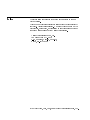
1. Use the following procedure when turning off the 42841A:
a. Turn off the DC bias current output.
b. Disconnect a DUT (Device Under Test) from the test fixture.
c. Turn off the 42841A LINE ON/OFF switch.
If turning off the 42841A power with DUT connected, the 42841A internal circuit may
be damaged.
2. Turn off all the power switches of the 42841A and the LCR meter when connecting or
disconnecting any connection involving the 42841A and the LCR meter.
C Copyright 2008 Agilent Technologies
○
Agilent 42841A Bias Current Source
Manual Change
February 2003
Printed in Japan
Change 1
Change option numbers described in Operation Manual.
Old Option Number
New Option Number
907 (Front Handle Kit)
same as the left number
908 (Rack Mount Kit)
same as the left number
909 (Rack Flange and Handle Kit)
same as the left number
ABA (Add Operation Manual (English))
ABJ (Add Operation Manual (Japanese))
915 (Add Service Manual)
same as the left number
1. In the previous system, the option number is used to choose the language of the operation manual
(standard accessory). In the new option system, it is used to add an operation manual (optional
accessory) of the language the customer desires.
© Copyright Agilent Technologies Japan, Ltd. 2003
Remark
1
Safety Summary
When you notice any of the unusual conditions listed below, immediately
terminate operation and disconnect the power cable.
Contact your local Agilent Technologies sales representative or
authorized service company for repair of the instrument. If you continue
to operate without repairing the instrument, there is a potential fire or
shock hazard for the operator.
n Instrument operates abnormally.
n Instrument emits abnormal noise, smell, smoke or a spark-like light
during the operation.
n Instrument generates high temperature or electrical shock during
operation.
n Power cable, plug, or receptacle on instrument is damaged.
n Foreign substance or liquid has fallen into the instrument.
Agilent 42841A BIAS CURRENT SOURCE
OPERATION MANUAL
SERIAL NUMBERS
This manual applies directly to instruments with serial number prex
2915J
For additional important information about serial numbers, read
\Serial Number" in Chapter 4 of this Manual.
Agilent Part No. 42841-90010
Printed in JAPAN
Fifth Edition
March 2000
Notice
The information contained in this document is subject to change
without notice.
This document contains proprietary information that is protected by
copyright. All rights are reserved. No part of this document may be
photocopied, reproduced, or translated to another language without
the prior written consent of the Agilent Technologies.
Agilent Technologies Japan, Ltd.
Component Test PGU-Kobe
1-3-2, Murotani, Nishi-ku, Kobe-shi,
Hyogo, 651-2241 Japan
c Copyright 1989, 1991, 1996, 2000 Agilent Technologies Japan, Ltd.
Manual Printing
History
The manual printing date and part number indicate its current
edition. The printing date changes when a new edition is printed.
(Minor corrections and updates that are incorporated at reprint do
not cause the date to change.) The manual part number changes
when extensive technical changes are incorporated.
April 1989 : : : : : : : : : : : : : : First Edition (part number: 42841-90000)
April 1991 : : : : : : : : : : : : Second Edition (part number: 42841-90000)
December 1991 : : : : : : : : Third Edition (part number: 42841-90000)
December 1996 : : : : : : : Fourth Edition (part number: 42841-90000)
March 2000 : : : : : : : : : : : : : Fifth Edition (part number: 42841-90010)
iii
Certification
Warranty
Limitation Of
Warranty
Agilent Technologies certies that this product met its published
specications at the time of shipment from the factory. Agilent
Technologies further certies that its calibration measurements are
traceable to the United States National Institute of Standards and
Technology, to the extent allowed by the Institution's calibration
facility, or to the calibration facilities of other International
Standards Organization members.
This Agilent Technologies instrument product is warranted against
defects in material and workmanship for a period of one year from
the date of shipment, except that in the case of certain components
listed in General Information of this manual, the warranty shall
be for the specied period. During the warranty period, Agilent
Technologies will, at its option, either repair or replace products that
prove to be defective.
For warranty service or repair, this product must be returned
to a service facility designated by Agilent Technologies. Buyer
shall prepay shipping charges to Agilent Technologies and Agilent
Technologies shall pay shipping charges to return the product to
Buyer. However, Buyer shall pay all shipping charges, duties, and
taxes for products returned to Agilent Technologies from another
country.
Agilent Technologies warrants that its software and rmware
designated by Agilent Technologies for use with an instrument will
execute its programming instruction when property installed on that
instrument. Agilent Technologies does not warrant that the operation
of the instrument, or software, or rmware will be uninterrupted or
error free.
The foregoing warranty shall not apply to defects resulting from
improper or inadequate maintenance by Buyer, Buyer-supplied
software or interfacing, unauthorized modication or misuse,
operation outside the environmental specications for the product, or
improper site preparation or maintenance.
No other warranty is expressed or implied. Agilent Technologies
specically disclaims the implied warranties of merchantability and
tness for a particular purpose.
iv
Exclusive Remedies
Assistance
The remedies provided herein are buyer's sole and exclusive remedies.
Agilent Technologies shall not be liable for any direct, indirect, special,
incidental, or consequential damages, whether based on contract, tort,
or any other legal theory.
Product maintenance agreements and other customer assistance
agreements are available for Agilent Technologies products.
For any assistance, contact your nearest Agilent Technologies Sales
and Service Oce. Addresses are provided at the back of this
manual.
v
Safety Summary
The following general safety precautions must be observed during all
phases of operation, service, and repair of this instrument. Failure
to comply with these precautions or with specic WARNINGS
elsewhere in this manual may impair the protection provided by
the equipment. In addition it violates safety standards of design,
manufacture, and intended use of the instrument.
The Agilent Technologies assumes no liability for the customer's
failure to comply with these requirements.
Note
42841A comply with INSTALLATION CATEGORY II and
POLLUTION DEGREE 2 in IEC1010-1. 42841A are INDOOR USE
product.
Note
LEDs in this product are Class 1 in accordance with IEC825-1.
CLASS 1 LED PRODUCT
Ground The Instrument
To avoid electric shock hazard, the instrument chassis and cabinet
must be connected to a safety earth ground by the supplied power
cable with earth blade.
DO NOT Operate In An
Explosive Atmosphere
Do not operate the instrument in the presence of ammable gasses or
fumes. Operation of any electrical instrument in such an environment
constitutes a denite safety hazard.
Keep Away From Live
Circuits
Operating personnel must not remove instrument covers. Component
replacement and internal adjustments must be made by qualied
maintenance personnel. Do not replace components with the power
cable connected. Under certain conditions, dangerous voltages may
exist even with the power cable removed. To avoid injuries, always
disconnect power and discharge circuits before touching them.
DO NOT Service Or
Adjust Alone
Do not attempt internal service or adjustment unless another person,
capable of rendering rst aid and resuscitation, is present.
DO NOT Substitute
Parts Or Modify
Instrument
Because of the danger of introducing additional hazards, do not
install substitute parts or perform unauthorized modications to the
instrument. Return the instrument to a Agilent Technologies Sales
and Service Oce for service and repair to ensure that safety features
are maintained.
vi
Dangerous Procedure
Warnings
Warning
, such as the example below, precede potentially dangerous
procedures throughout this manual. Instructions contained in the
warnings must be followed.
Warnings
Dangerous voltages, capable of causing death, are present in this
instrument. Use extreme caution when handling, testing, and adjusting
this instrument.
vii
Safety Symbols
General denitions of safety symbols used on equipment or in
manuals are listed below.
Instruction manual symbol: the product is marked
with this symbol when it is necessary for the user to
refer to the instruction manual.
Alternating current.
Direct current.
On (Supply).
O (Supply).
In position of push-button switch.
Out position of push-button switch.
Frame (or chassis) terminal. A connection to the
frame (chassis) of the equipment which normally
include all exposed metal structures.
This
sign denotes a hazard. It calls
attention to a procedure, practice, condition or the
like, which, if not correctly performed or adhered to,
could result in injury or death to personnel.
This
sign denotes a hazard. It calls
attention to a procedure, practice, condition or the
like, which, if not correctly performed or adhered to,
could result in damage to or destruction of part or all
of the product.
This
sign denotes important information. It
calls attention to a procedure, practice, condition or
the like, which is essential to highlight.
Axed to product containing static sensitive devices
use anti-static handling procedures to prevent
electrostatic discharge damage to component.
Warning
Caution
Note
viii
How to Use This
Manual
Chapter 1
Installation
Chapter 2
Product Overview
Chapter 3
Operation Procedure
and Examples
Chapter 4
General Information
Chapter 5
Performance Test
Appendix A
Manual Changes
This is the Operation Manual for the 42841A Bias Current Source
including system operation combining with the 4284A, 42842A/B,
and 42843A. This manual contains installation, conguration,
operation, and performance test in the procedure following six
chapters. After you receive your 42841A, begin with chapter 1.
The 42841A is designed to compose a high DC current biased
impedance measurement system, combining with the 4284A. Refer to
the 4284A Operation Manual (Agilent Part Number 04284-90000) for
operation 4284A, before reading this Operation Manual.
For error messages of the 42841A, 42842A/B, and 42843A in use with
the 4284A, refer to the 4284A Operation Manual Appendix B Error
Message And System Message .
This chapter provides unpacking, initial inspection, and preparation
information necessary for you to know before applying AC power.
This chapter provides information including a product overview.
This chapter provides the basic operation procedures measurement
techniques, practical measurement examples, and remote control
capability information.
This chapter provides specications, supplemental performance
characteristics, and other general information on the 42841A.
This chapter provides the performance tests for the 42841A used
for incoming inspection and verication that your instrument is
completely calibrated.
Appendix A contains Manual Changes and provides information for
using this manual with an 42841As manufactured before the printing
date of the manual.
ix
Typeface
Conventions
Bold
icons
Italics
Computer
4HARDKEYS5
NNNNNNNNNNNNNNNNNNNNNNNNNN
SOFTKEYS
x
Boldface type is used when a term is dened.
For example:
are symbols.
Italic type is used for emphasis and for titles
of manuals and other publications.
Italic type is also used for keyboard entries
when a name or a variable must be typed in
place of the words in italics. For example:
copy lename means to type the word copy,
to type a space, and then to type the name of
a le such as file1.
Computer font is used for on-screen prompts
and messages.
Labeled keys on the instrument front panel
are enclosed in 4 5.
Softkeys located to the right of the LCD are
enclosed in .
NNNNN
Contents
1.
Installation and Set Up Guide
2.
Product Overview
Incoming Inspection . . . . . . . . .
Power Requirements . . . . . . . . .
Power Cable . . . . . . . . . . . .
Line Voltage and Fuse Selection . . . .
Line Voltage Selection . . . . . . . .
Fuse Selection . . . . . . . . .
Operation Environment . . . . . . . .
Electromagnetic Compatibility . . . . .
Ventilation Requirements . . . . . . .
Instruction for Cleaning . . . . . . . .
Rack/Handle Installation . . . . . . .
Option 907 Handle Kit . . . . . . .
Installing the Handle . . . . . . .
Option 908 Rack Flange Kit . . . . .
Mounting the Rack . . . . . . . .
Option 909 Rack Flange & Handle Kit
Mounting the Handle and Rack . .
.
.
.
.
.
.
.
.
.
.
.
.
.
.
.
.
.
.
.
.
.
.
.
.
.
.
.
.
.
.
.
.
.
.
.
.
.
.
.
.
.
.
.
.
.
.
.
.
.
.
.
.
.
.
.
.
.
.
.
.
.
.
.
.
.
.
.
.
.
.
.
.
.
.
.
.
.
.
.
.
.
.
.
.
.
1-1
1-2
1-2
1-4
1-4
1-4
1-5
1-5
1-5
1-6
1-6
1-7
1-7
1-7
1-7
1-7
1-7
Introduction . . . . . . . . . . . . . . . . .
Product Introduction . . . . . . . . . . . . .
A Tour of the Front Panel . . . . . . . . . .
(1) LINE On/O . . . . . . . . . . . . .
(2) Operation Indicator . . . . . . . . . .
(3) DC Bias Indicator . . . . . . . . . . .
(4) DC Bias Current Output . . . . . . . .
(5) Fixture Connection Detector . . . . . .
(6) Fixture Guide Holes and Threaded Studs .
A Tour of Rear Panel . . . . . . . . . . . .
(1) Bias Current Interface Connectors . . . .
(2) Line Voltage Selector . . . . . . . . .
(3) Line Fuse Holder . . . . . . . . . . .
(4) Line Input Receptacle . . . . . . . . .
.
.
.
.
.
.
.
.
.
.
.
.
.
.
2-1
2-1
2-2
2-2
2-2
2-3
2-3
2-3
2-3
2-4
2-4
2-4
2-4
2-4
Contents-1
3.
4.
Contents-2
Operation Procedure and Examples
Introduction . . . . . . . . . . . . .
Operation Limitations . . . . . . . .
4284A Systems . . . . . . . . . . .
20A System . . . . . . . . . . .
40A System . . . . . . . . . . .
Operation Limitations . . . . . .
4285A System . . . . . . . . . . .
Operation Limitations . . . . . .
Instrument Connections . . . . . .
4284A(20A) System . . . . . . . .
4284A(40A) System . . . . . . . .
4285A System . . . . . . . . . . .
Interconnecting Units . . . . . .
Basic Measurement Procedure . . . . .
Measurement Procedure . . . . . . .
Conrm the System Condition . . .
Set Up the Measurement Conditions
Performing Error Correction . . . .
Cable Length Correction . . . .
Open Correction . . . . . . . .
Short Correction . . . . . . . .
Performing Short Correction . . .
Load Correction . . . . . . . .
Connect DUT to the Test Fixture .
Enable the DC Bias Output . . . .
Performing the Measurement . . . .
Disable the DC Bias Output. . . .
Measurement Terminals Extension . . .
Inductance Measurements . . . . . . .
DC Bias Current List Sweep . . . . . .
Remote Control . . . . . . . . . . .
Remote Control Capability . . . . .
Sample Program . . . . . . . . . .
General Information
Introduction . . . . . . .
Serial Number . . . . . .
Specications . . . . . .
DC Bias Current Output
Output Voltage . . . .
Applicable Test Signal .
Interface . . . . . . .
Other Options . . . . .
Furnished Accessories . .
Test Fixtures . . . . .
Other Accessories . . .
Line Voltage . . . . . .
Line Frequency . . . . .
.
.
.
.
.
.
.
.
.
.
.
.
.
.
.
.
.
.
.
.
.
.
.
.
.
.
.
.
.
.
.
.
.
.
.
.
.
.
.
.
.
.
.
.
.
.
.
.
.
.
.
.
.
.
.
.
.
.
.
.
.
.
.
.
.
.
.
.
.
.
.
.
.
.
.
.
.
.
.
.
.
.
.
.
.
.
.
.
.
.
.
.
.
.
.
.
.
.
.
.
.
.
.
.
.
.
.
.
.
.
.
.
.
.
.
.
.
.
.
.
.
.
.
.
.
.
.
.
.
.
.
.
.
.
.
.
.
.
.
.
.
.
.
.
.
.
.
.
.
.
.
.
.
.
.
.
.
.
.
.
.
.
.
.
.
.
.
.
.
.
.
.
.
.
.
.
.
.
.
.
.
.
.
.
.
.
.
.
.
.
.
.
.
.
.
.
.
.
.
.
.
.
.
.
.
.
.
.
.
.
.
.
.
.
.
.
.
.
.
.
.
.
.
.
.
.
.
.
.
.
.
.
.
.
.
.
.
.
.
.
.
.
.
3-1
3-1
3-1
3-1
3-1
3-2
3-2
3-2
3-3
3-3
3-5
3-7
3-9
3-11
3-11
3-12
3-12
3-12
3-12
3-12
3-13
3-13
3-13
3-13
3-14
3-14
3-16
3-17
3-18
3-27
3-28
3-28
3-29
.
.
.
.
.
.
.
.
.
.
.
.
.
.
.
.
.
.
.
.
.
.
.
.
.
.
.
.
.
.
.
.
.
.
.
.
.
.
.
.
.
.
.
.
.
.
.
.
.
.
.
.
.
.
.
.
.
.
.
.
.
.
.
.
.
4-1
4-1
4-2
4-2
4-3
4-3
4-3
4-3
4-3
4-4
4-4
4-4
4-4
Power Consumption . . . . . . . . . . . . .
Operating Temperature . . . . . . . . . . . .
Operating Humidity . . . . . . . . . . . . .
Operating Altitude . . . . . . . . . . . . . .
Dimensions . . . . . . . . . . . . . . . . .
Weight . . . . . . . . . . . . . . . . . . .
Supplemental Performance Characteristics . . . . .
42841A Measurement Accuracy (used for 4284A) .
L and jZj Accuracy : Ae (for L accuracy; Dx 0.1)
D Accuracy : De (Dx 0.1) . . . . . . . . .
Accuracy : e . . . . . . . . . . . . . .
Rs (Equivalent Series Resistance) Accuracy : Rse
(Dx 0.1) . . . . . . . . . . . . . . .
Additional Error Caused by 42842A/B . . . . .
L and jZj Additional Error (for L accuracy; Dx <
0.1) . . . . . . . . . . . . . . . . . .
D Additional Error : D1 ( Dx < 0.1 ) . . . . .
Additional Error : 1 . . . . . . . . . . .
Rs (Equivalent Series Resistance) Additional Error :
Rs1 (Dx < 0.1) . . . . . . . . . . . . .
Measurement Accuracy (used for 4285A) . . . .
L and jZj Accuracy : Ae (for L accuracy; Dx0.1
or Qx 10) . . . . . . . . . . . . . . .
D Accuracy : De (Dx 0.1) . . . . . . . . .
Accuracy : . . . . . . . . . . . . . . . .
Rs (Equivalent Series Resistance) Accuracy : Re
42842C Additional Error . . . . . . . . . . .
L and jZj Additional Error: A1 . . . . . . . .
D Additional Error . . . . . . . . . . . . .
Additional Error : . . . . . . . . . . . .
Rs (Equivalent Series Resistance) Additional Error
: R1 . . . . . . . . . . . . . . . . . .
Bias Current Settling Time . . . . . . . . . .
Signal Voltage ALC Operation Area . . . . . .
Measurement Error Calculation Example . . . . .
Storage and Repacking . . . . . . . . . . . . .
Environment . . . . . . . . . . . . . . . . .
Original Packaging . . . . . . . . . . . . . .
Other Packaging . . . . . . . . . . . . . . .
5.
Performance Test
Introduction . . . . . . . . .
Test Equipment . . . . . .
Performance Test Record . .
Calculation Sheet . . . . . .
Calibration Cycle . . . . . .
DC Bias Current Accuracy Test
Test Equipment . . . . . .
Procedure . . . . . . . . .
Resistor Box Calibration . . .
Test Equipment . . . . . .
.
.
.
.
.
.
.
.
.
.
.
.
.
.
.
.
.
.
.
.
.
.
.
.
.
.
.
.
.
.
.
.
.
.
.
.
.
.
.
.
.
.
.
.
.
.
.
.
.
.
.
.
.
.
.
.
.
.
.
.
.
.
.
.
.
.
.
.
.
.
.
.
.
.
.
.
.
.
.
.
.
.
.
.
.
.
.
.
.
.
4-4
4-4
4-4
4-4
4-4
4-4
4-4
4-4
4-4
4-6
4-6
4-6
4-7
4-7
4-8
4-8
4-8
4-13
4-13
4-13
4-14
4-14
4-14
4-17
4-17
4-17
4-17
4-18
4-18
4-18
4-21
4-21
4-21
4-21
5-1
5-1
5-2
5-2
5-2
5-3
5-3
5-4
5-7
5-7
Contents-3
Procedure . . . . . . . . . . . . . . . . . .
Calicuation Sheet . . . . . . . . . . . . . . . .
Performance Test Record . . . . . . . . . . . .
A.
Manual Changes
Introduction . . . . . . . . . . . . . . . . . .
Manual Changes . . . . . . . . . . . . . . . .
Index
Contents-4
5-7
5-9
5-11
A-1
A-1
Figures
1-1.
1-2.
1-3.
2-1.
2-2.
3-1.
3-2.
3-3.
3-4.
3-5.
3-6.
3-7.
3-8.
3-9.
3-10.
3-11.
3-12.
3-13.
3-14.
3-15.
3-16.
3-17.
3-18.
3-19.
3-20.
3-21.
3-22.
4-1.
4-2.
4-3.
4-4.
4-5.
4-6.
4-7.
4-8.
Power Cable Supplied . . . . . . . . . . . . .
Line Voltage Selector . . . . . . . . . . . . .
Rack Mount Kits Installation . . . . . . . . .
Front Panel Overview . . . . . . . . . . . . .
Rear Panel Overview . . . . . . . . . . . . .
Cable connection for the 4284A (20A) system . .
Cable connection for an 4284A(40A) system . . .
Cable connections for an 4285A system . . . . .
Cable connections for an 4285A system(adding the
42851A) . . . . . . . . . . . . . . . . .
42842A/B/C Bias Current Test Fixture Connection
Shorting the Measurement Terminals . . . . . .
Moving Cursor to the FUNC Field . . . . . . .
Softkey Path To The Ls-Rs softkey . . . . . .
Moving Cursor to the FREQ Field . . . . . . .
Measurement Frequency Value Entry . . . . . .
Moving Cursor to the BIAS Field . . . . . . .
Bias Current Value Entry (before pressing the A
softkey) . . . . . . . . . . . . . . . . .
Moving Cursor to the INTEG Field . . . . . . .
Select Measurement Setup Page . . . . . . . .
Move Cursor to the ALC eld. . . . . . . . . .
To Enable the Automatic Level Control Function .
Set Cable Length . . . . . . . . . . . . . . .
Connecting the Furnished Shorting Bar . . . . .
Move the Cursor to the SHORT Field . . . . . .
System Message When the Short Measurement is
Completed . . . . . . . . . . . . . . . .
Ferrite-Cored Inductor Measurement Results . . .
DC Bias Current List Sweep Result . . . . . . .
Serial Number Plate . . . . . . . . . . . . .
Temperature Induced Setting Error . . . . . . .
DC Bias Output Range . . . . . . . . . . . .
4284A Accuracy . . . . . . . . . . . . . . .
4284A Basic Accuracy Line Selection Chart . . .
Inductance measurement accuracy of 42841A ( 20A
Conguration ) . . . . . . . . . . . . . .
Impedance measurement accuracy of 42841A ( 20A
Conguration ) . . . . . . . . . . . . . .
Temperature additional error of 42841A ( 20A
Conguration) . . . . . . . . . . . . . .
NNNNNNNNNNNNNNNNN
NNNNN
1-3
1-4
1-6
2-2
2-4
3-4
3-6
3-7
3-8
3-10
3-13
3-18
3-19
3-19
3-20
3-20
3-21
3-21
3-22
3-22
3-23
3-24
3-24
3-25
3-25
3-26
3-27
4-1
4-2
4-3
4-5
4-5
4-9
4-10
4-10
Contents-5
4-9. Inductance measurement error of 42841A ( 40A
Conguration ) . . . . . . . . . . . . . .
4-10. Impedance measurement accuracy of 42841A ( 40A
Conguration ) . . . . . . . . . . . . . .
4-11. Temperature additional error of 42841A ( 40A
Conguration ) . . . . . . . . . . . . . .
4-12. Additional Inductance Error of the 42842C . . .
4-13. Additional Impedance Error of the 42842C . . .
5-1. Bias Current Accuracy Test Setup . . . . . . .
5-2. Resistor Box Calibration Setup . . . . . . . . .
Contents-6
4-11
4-12
4-12
4-15
4-16
5-4
5-7
Tables
1-1.
1-2.
1-3.
1-4.
3-1.
3-2.
4-1.
4-2.
5-1.
5-2.
5-3.
5-4.
5-5.
5-6.
5-7.
A-1.
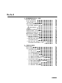
42841A Contents . . . . . . . . . . . . .
Line Voltage Selection . . . . . . . . . . .
Fuse Selection . . . . . . . . . . . . . .
Rack Mount Kits . . . . . . . . . . . . .
Allowable Current Capacity Of The Wire . .
Current Capacity Reducing Rate . . . . . .
DC Bias Current Accuracy . . . . . . . .
Accuracy Chart Selection Table . . . . . .
Recommended Test Equipment . . . . . . .
Bias Current Accuracy Specication . . . .
Recommended Test Equipment . . . . . . .
1A Range Bias Current Accuracy Test Limit .
5A Range Bias Current Accuracy Test Limit .
20A Range Bias Current Accuracy Test Limit
Recommended Test Equipment . . . . . . .
Manual Changes by Serial Number . . . . .
.
.
.
.
.
.
.
.
.
.
.
.
.
.
.
.
.
.
.
.
.
.
.
.
.
.
.
.
.
.
.
.
1-2
1-4
1-4
1-6
3-17
3-17
4-2
4-7
5-2
5-3
5-3
5-5
5-6
5-6
5-7
A-1
Contents-7
1
Installation and Set Up Guide
This chapter provides the information necessary for performing an
incoming inspection and setting up the 42841A. The main topics in
this chapter are:
Incoming Inspection
Power requirements
Line Voltage and Fuse Selection
Operation Environment
Electromagnetic Compatibility
Ventilation Requirements
Instruction for Cleaning
Rack/Handle Installation
Incoming Inspection
Warning
To avoid hazardous electrical shock, do not turn on the 42841A
when there are signs of shipping damage to any portion of the outer
enclosure (for example, covers, panel, or display)
Inspect the shipping container for damage. If the shipping container
or cushioning material is damaged, it should be kept until the
contents of the shipment have been checked for completeness and
the 42841A has been checked mechanically and electrically. The
contents of the shipment should be as listed in Table 1-1. If the
contents are incomplete, if there is mechanical damage or defect, or if
the analyzer does not pass the power-on selftests, notify the nearest
Agilent Technologies oce. If the shipping container is damaged,
or the cushioning material shows signs of unusual stress, notify the
carrier as well as the Agilent Technologies oce. Keep the shipping
materials for the carrier's inspection.
Manual Change
1-1
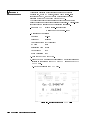
Table 1-1. 42841A Contents
42841A
Description
Qty. Agilent Part Number
Bias Current Interface Cable
1
42841-61640
Power cable1
1
|
Operation Manual
1
42841-90010
1
5061-9690
1
5061-9678
1
5061-9684
Option 907 Handle Kit
Handle kit
Option 908 Rack Flange Kit
Rack Flange Kit
Option 909 Rack Flange & Handle Kit
Rack Flange & Handle Kit
1 Power Cable depends on where the instrument is used, see \Power Cable".
Power Requirements
Power Cable
Warning
The 42841A requires the following power source:
Voltage : 90 to 132 Vac, 198 to 252 Vac
Frequency : 47 to 66 Hz
Power : 600 VA maximum
In accordance with international safety standards, this instrument
is equipped with a three-wire power cable. When connected to an
appropriate ac power outlet, this cable grounds the instrument
frame.
The type of power cable shipped with each instrument depends on
the country of destination. Refer to Figure 1-1 for the part numbers
of the power cables available.
For protection from electrical shock, the power cable ground must not
be defeated.
The power plug must be plugged into an outlet that provides a
protective earth ground connection.
1-2
Manual Change
Figure 1-1. Power Cable Supplied
Manual Change
1-3
Line Voltage and
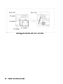
Fuse Selection
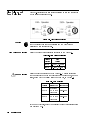
Figure 1-2 illustrates the line voltage selection switch and fuseholder
on the instrument's rear panel.
Figure 1-2. Line Voltage Selector
Caution
Line Voltage Selection
Before connecting the instrument to the power source, make sure
that the correct fuse has been installed and the Line Voltage
Selection Switch is correctly set.
Select the proper voltage selector according to the Table 1-2.
Table 1-2. Line Voltage Selection
Voltage
Selector
Line
Voltage
115 V 90{132 V, 47{66 Hz
230 V 198{252 V, 47{66 Hz
Fuse Selection
Select proper fuse according to the Table 1-3. Current ratings for
the fuse are printed under the fuseholder on the rear panel, and are
listed, along with the fuse's Agilent Part number, in Table 1-3.
Table 1-3. Fuse Selection
Fuse
Fuse
Operating
Voltage Rating/Type Part Number
8A 250Vac
115 V UL/CSA type
Time Delay
5A 250Vac
230 V UL/CSA type
Time Delay
2110-0383
2110-0030
If you need this fuse,contact your nearest Agilent Technologies Sales
and Service Oce.
1-4
Manual Change
To remove the fuse, turn the fuse holder counterclockwise until the
fuse pops out.
Caution
Operation
Environment
Note
Electromagnetic
Compatibility
Ventilation
Requirements
Use the proper fuse for the line voltage selected. Use only fuses with
the required current rating and of the specied type as replacements.
DO NOT use a mended fuse or short-circuit the fuse-holder in order
to by-pass a blown fuse. Find out what caused the fuse to blow!
The 42841A must be operated under within the following
environment conditions, and sucient space must be kept behind the
42841A to avoid obstructing the air ow of the cooling fans.
Temperature: 0 C to 55 C
Humidity:
less than 95% RH at 40C
The 42841A must be protected from temperature extremes which
could cause condensation within the instrument.
This product has been designed and tested to the requirements of
the Electromagnetic Compatibility (EMC) Directive 89/336/EEC.
To use a properly shielded cable or shielded coaxial cable (such as
those recommended in the General Information and the Performance
Test) to connect each of the ports to their respective controllers,
peripherals, equipments or devices may ensure to meet the
requirements.
To ensure adequate ventilation, make sure that there is adequate
clearance around the 42841A.
Manual Change
1-5
Instruction for
Cleaning
Rack/Handle
Installation
To prevent electrical shock, disconnect the 42841A power cable from
the receptacle before cleaning. Use a dry cloth or a cloth slightly
dipped in water to clean the casing. Do not attempt to clean the
42841A internally.
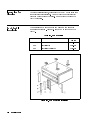
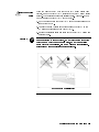
The analyzer can be rack mounted and used as a component in
a measurement system. Figure 1-3 shows how to rack mount the
42841A.
Table 1-4. Rack Mount Kits
Option
Description
907
Handle Kit
5061-9690
908
Rack Flange Kit
5061-9678
909
Rack Flange & Handle Kit
5061-9684
Figure 1-3. Rack Mount Kits Installation
1-6
Manual Change
Agilent Part
Number
Option 907 Handle Kit
Option 907 is a handle kit containing a pair of handles and the
necessary hardware to attach them to the instrument.
Installing the Handle
1. Remove the adhesive-backed trim strips 1 from the left and right
front sides of the 42841A. (Refer to Figure 1-3.)
2. Attach the front handles 2 to the sides using the screws provided.
3. Attach the trim strips 3 to the handles.
Option 908 Rack Flange
Kit
Option 908 is a rack ange kit containing a pair of anges and
the necessary hardware to mount them to the instrument in an
equipment rack with 482.6 mm (19 inches) horizontal spacing.
Mounting the Rack
1. Remove the adhesive-backed trim strips 1 from the left and right
front sides of the 42841A. (Refer to Figure 1-3.)
2. Attach the rack mount ange 4 to the left and right front sides of
the 42841A using the screws provided.
3. Remove all four feet 5 (lift bar on the inner side of the foot, and
slide the foot toward the bar.)
Option 909 Rack Flange
& Handle Kit
Option 909 is a rack mount kit containing a pair of anges and the
necessary hardware to mount them to an instrument which has
handles attached, in an equipment rack with 482.6 mm (19 inches)
spacing.
Mounting the Handle and Rack
1. Remove the adhesive-backed trim strips 1 from the left and right
front sides of the 42841A.
2. Attach the front handle 3 and the rack mount ange 5 together
on the left and right front sides of the 42841A using the screws
provided.
3. Remove all four feet (lift bar on the inner side of the foot, and
slide the foot toward the bar).
Manual Change
1-7
2
Product Overview
Introduction
Product
Introduction
This chapter contains the information you will need to know before
operating the Agilent Model 42841A Bias Current Source, such as the
relation between the 4284A/4285A Precision LCR meter and 42841A,
and each name of the 42841A's parts and their function.
The 42841A is a bias current source for use with the 4284A(with
an Option 002 Bias Current Interface) or with the 4285A(with an
Option 002 Accessory Control Interface). So all measurement setups
including the DC current bias can be set using the 4284A/4285A
front panel keys.
The 42841A using with 4284A(20Hz - 1MHz) covers DC current
bias from 0.01A to 20A in three ranges. Two 42841As can be
paralleled to supply the maximum of 40A DC current bias combining
the 42842B Bias Current Test Fixture and by the 42843A Bias
Current Cable. For system conguration, refer to \ Instrument
Connections" in Chapter 3.
The 42841A can also be used with the 4285A(75kHz - 30MHz) and
the 42842C test xture for biased measurements. When the 42841A
is used with the 42841A, the DC current bias range of 0.01A to 10A
is covered.
The 4284A when used with the 42841A, 42842A/B, and 42843A
oers an additional error of 1% (supplemental performance
characteristics), over frequency range from 1kHz to 1MHz.
The 4284A's some measurement functions are limited such as
measurement range and Option 001 Power Amplier/ DC Bias
option. For details, refer to \Operation Limitations" in Chapter 3.
Product Overview
2-1
A Tour of the Front
Panel
Figure 2-1 shows the 42841A's components on the front panel. A
description is given in the following paragraphs.
Figure 2-1. Front Panel Overview
(1) LINE On/Off
Power on/o switch. In the \ON" position all operating voltages
are applied to the instrument. In the \OFF" position NO operating
voltages are applied to the instrument.
(2) Operation Indicator
This Light Emitting Diode (LED) shows the 42841A's operation
status. This LED is ON while the 42841A is operated normally. If
the 42842A/B or 42843A are accidentally disconnected from the
42841A, the power will be automatically shut down and this LED
will go o. In this case, turn the line switch o, and wait for a few
seconds before turning it on again.
2-2
Product Overview
(3) DC Bias Indicator
This LED shows the 42841A's DC current bias status. When this
LED is lit, DC current bias is applied. When this LED is OFF, the
DC current bias is not applied.
(4) DC Bias Current Output
These connectors output the DC bias current, detects the xture
connection, detects over temperature of the xture, and checks status
of the xture cover.
(5) Fixture Connection Detector
This switch senses connection of 42842A/B or 42843A. If this switch
is asserted, the 42841A will shut down by itself for the operator's
safety.
(6) Fixture Guide Holes and Threaded Studs
These parts are used to mount the 42842A/B in front of the 42841A.
Product Overview
2-3
A Tour of Rear Panel
Figure 2-2 shows the 42841A's components on the rear panel. A
description is given in the following paragraphs.
Figure 2-2. Rear Panel Overview
(1) Bias Current Interface Connectors
These are the Bias Current Interface connectors. Use either the
connector A or B to interconnect the 42841A with the 4284A Option
002 Bias Current Interface or with the 4285A Option 002 Accessory
Control Interface using the furnished bias current interface cable.
The other connector is used to connect one more 42841A unit when a
40A maximum bias current system is congured.
(2) Line Voltage Selector
The switch used to match the 42841A to the AC operating voltage
being used. Refer to SECTION 1 to determine the correct operating
voltage.
(3) Line Fuse Holder
Fuse holder for the 42841A's line fuse. Refer to SECTION 1 to
determine the correct line fuse rating.
(4) Line Input Receptacle
AC power cord receptacle.
2-4
Product Overview
3
Operation Procedure and Examples
Introduction
Operation
Limitations
4284A Systems
This chapter discusses the following topics:
Operation limitations
Basic measurement procedures
Measurement hints
Practical measurement examples
Remote control function
When using the 42841A, the measurement conguration is selected
based on use. Each conguration has the following limitations.
This system conguration uses the 4284A (measurement frequency:
20Hz - 1MHz) with the 42841A and the 42842A/B. There are two
congurations for two bias current ranges. One is a 20A bias current
system and theother is a 40A bias current system.
20A System
The following equipment is necessary for the basic 20A system.
4284A Precision LCR Meter (with Option 002)
:1
42841A Bias Current Source
:1
42842A Bias Current Test Fixture
:1
16048A Test Lead
:1
Interface Cable(furnished with 42841A)
:1
40A System
The following equipment is necessary for the basic 40A system.
4284A Precision LCR Meter (with Option 002)
:1
42841A Bias Current Source
:2
42842B Bias Current Test Fixture
:1
42843A Bias Current Cable
:1
16048A Test Lead
:1
Interface Cable(furnished with 42841A)
:2
Operation Procedure and Examples
3-1
Operation Limitations
Some 4284A functions have limitations when used with the 42841A
and the 42842A/B. These limitations are:
Standard spot bias (1.5V or 2V) is disabled.
Option 001, Power Amplier/DC-bias, is disabled. So High Power
mode and DC current Isolation are turned OFF. The maximum
oscillator level is limited to 2Vrms, and the 640V DC-bias is
disabled.
Measurement range is limited to 10
and 100
ranges only.
Open compensation can not be used when the 42841A is used.
The cable length setting applies for the 1 m setting only.
For each of the above mentioned functions, refer to the 4284A
Operation Manual, Section 3, Display Format , and Section 4,
Measurement Setup .
4285A System
This system uses the 4285A(measurement frequency: 75kHz 30MHz) with the 42841A and 42842C. This is 10A bias current
system.
The following equipment is necessary for a basic 4285A bias current
system.
4285A Precision LCR Meter
:1
42841A Bias Current Source
:1
42842C Bias Current Test Fixture
:1
(Order the Option 001, SMD Test Fixture.)
16048A Test Lead
:1
Interface Cable (furnished with 42841A)
:1
Operation Limitations
Some 4285A functions have limitations when used with 42841A and
42842C. These limitations are:
Option 001, Internal DC Bias is disabled.
Cable length setting applies for the 1 m setting only.
Refer to the 4285A Precision LCR Meter Operation Manual for
details.
3-2
Operation Procedure and Examples
Instrument
Connections
Corresponding to each system conguration, use the following
procedures to connect the instruments.
Note
DO NOT use these congurations other than as described in this
section.
Caution
Use the furnished 42841A Interface Cable when connecting to the
4284A/4285A. DO NOT extend the Interface Cable.
4284A(20A) System
Connect the 4284A to the 42841A and the 42842A as shown in
Figure 3-1 using the following procedure.
1. Connect the Bias Current Interface connector of the 4284A to the
Bias Current Control Input A connector of the 42841A using the
furnished Bias Current Interface Cable.
2. Connect the 42842A directly to front panel of the 42841A as
shown in \ Interconnecting Units".
3. Connect the UNKNOWN connector of the 4284A to the TO
UNKNOWN Connector of the 42842A using the 16048A Test
Lead.
Operation Procedure and Examples
3-3
Figure 3-1. Cable connection for the 4284A (20A) system
3-4
Operation Procedure and Examples
4284A(40A) System
Caution
Connect the 4284A to the 42841A and the 42842A as shown in
Figure 3-2 using the following procedure.
1. Connect the 4284A Bias Current Interface Connector to the Bias
Current Input A Connector of the 42841A using the furnished
Bias Current Interface Cable(1).
2. Connect the 42841A Bias Current Control Input B Connector
connected to the 4284A in step 1 to the Bias Current Control
Input A Connector of the other 42841A using the furnished Bias
Current Interface Cable(2).
3. Connect the 42842B directly to front panel of the 42841A as
shown in \ Interconnecting Units".
4. Connect the 4284A UNKNOWN Connector to the TO
UNKNOWN Connector of 42842B using the 16048A Test Leads.
5. Connect the DC Bias Current Output Connector of the 42841A
which is not connected with the 42842B and DC Bias Current
Input Connector of the 42842B side panel using an 42843A Bias
Current Cable.
When in the 40A conguration shown in Figure 3-2 DO NOT
turn o a single 42841A or DO NOT disconnect the Bias Current
Interface Cable. When you change the conguration from 40A to
20A, you must completely disconnect one of the 42841As, its Bias
Current Interface Cable, and the 42843A Bias Current Cable.
Operation Procedure and Examples
3-5
Figure 3-2. Cable connection for an 4284A(40A) system
3-6
Operation Procedure and Examples
4285A System
Connect the 4285A to the 42841A and the 42842C as shown in
Figure 3-3 using the following procedure.
1. Connect the 4285A Bias Current Interface connector to the
42841A Bias Current Control Input A connector using the
furnished Bias Current Interface Cable.
2. Connect the 42842C directly to the front panel of the 42841A as
shown in \ Interconnecting Units".
3. Connect 4285A UNKNOWN connector to the TO UNKNOWN
Connector of the 42842C using the 16048A Test Leads.
Figure 3-3. Cable connections for an 4285A system
Operation Procedure and Examples
3-7
When switching between DC current bias measurement and Q
measurement when using an 4285A system with an 42851A precision
Q adapter, setup as shown in Figure 3-4.
You can not simultaneously use an 42841A and an 42851A, but you
can use them alternately by using the following procedure when
connecting the rear panel control cable. For information on using the
42851A refer to the 4285A OPERATION MANUAL, Getting Started
Guide and the 42851A OPERAION MANUAL.
1. Reconnect the measurement connector of the 4285A to the 42851A
by BNC cables.
2. Change the status to 42851A mode using the Q ADAPTER
softkey in the Accessory I/F(#002) eld in the 4285A system
conguration page.
NNNNNNNNNNNNNNNNNNNNNNNNNNNNN
Note
If serial number of the 42851A is lower than \2946J00187" in the
conguration shown in Figure 3-4, you must reconnect the 42851A's
accessory control interface cable directly to the 4285As interface
when changing to the Q measurement mode using the 42851A. If you
want to use the 42851A in the conguration shown in Figure 3-4,
contact your nearest Agilent Technologies oce.
Figure 3-4. Cable connections for an 4285A system(adding the 42851A)
3-8
Operation Procedure and Examples
Interconnecting
Units
Warning
When you use the 42841A with the 42842A/B/C Bias Current Test
Fixture, mount the 42842A/B/C directly to the 42841A Bias Current
Source. The connection procedure is listed below. Figure 3-5 shows
how to connect the 42842A/B/C to the 42841A.
1. Put the guide rods of the 42842A/B/C into the guide holes in the
front of the 42841A.
2. Connect the Bias Current output terminal of the 42841A to the
DC Bias input terminal of the 42842A/B/C.
3. Rotate the retaining screws in front of the 42842A/B/C clockwise
until they lock.
The 42842A/B/C mounted on the 42841A must be placed so that it
can be supported by the workbench. DO NOT stack three boxes (two
42841As and a 4284A) on top of each other, DO NOT put anything
on the 42842A/B/C test fixture, and DO NOT lean on the test fixture.
Doing this may cause the instrument to tumble over.
Recommended Physical Setup
Operation Procedure and Examples
3-9
Figure 3-5. 42842A/B/C Bias Current Test Fixture Connection
Warning
The 42842B can be used in a 20A current bias system. But in this
case, hazardous voltage will exist at the unused bias current input
connector of the 42842B. Put the red protective connector caps
on unused input connectors of the 42842B. DO NOT try to put a
conductive object into the unused 42842B input connector.
3-10
Operation Procedure and Examples
Basic Measurement
Procedure
The measurement procedure for applying a high current DC bias is
the same as for standard 4284A/4285A operation. All measurement
conditions can be set using the front panel keys of the 4284A/4285A.
When the 4284A is combined with the (two) 42841A(s), a current
bias of 0.01A to 20A (40A) can be set on the BIAS eld on the
MEASUREMENT DISPLAY page or the MEASUREMENT SETUP
page. Option 002 installation can be monitored on the I BIAS I/F
(#002) eld on the CONFIGURATION page.
For details on the 4284A's operation, refer to the 4284A Operation
Manual, Section 6, Measurement Procedure And Examples . For the
42841A's error messages when combined with an 4284A, refer to
4284A Operation Manual, Appendix B, Error Message And System
Message .
For details on the 4285A's operation, refer to the 4285A Operation
Manual, Getting Started Guide .
Note
Measurement
Procedure
Note
The 42841A will automatically shut down the output when it detects
disconnection of the 42842A/B/C or the 42843A. Connect the
42842A/B/C or the 42843A to the 42841A before turning it on.
A typical high DC current biased measurement procedure is as
follows.
1. Make sure that Option 002 is installed at the system cong page.
When using the 4285A, set to the I BIAS conguration at this
step.
2. Set up the measurement conditions.
3. Perform error correction.
When using the 4285A, CABLE CORRECTION for a 1 m cable
must have already been accomplished.
4. Connect the device under test (DUT) to the measurement
terminals.
5. Press the 4DC BIAS5 key, to enable the DC bias output.
6. Perform the measurement.
7. Press the 4DC BIAS5 key, to disable the DC bias output.
Operation Procedure and Examples
3-11
Confirm the System Condition
Make sure that I BIAS I/F(#002) in case of the 4284A,
ACCESSORY I/F(#002) in case of the 4285A, is already
installed in SYSTEM/CONFIG page which is displayed when the
4CATALOG/SYSTEM5 and SYSTEM CONFIG is pressed. In a case of
the 4285A, it must set to DC Current Bias Measurement Mode by
pressing I BIAS .
NNNNNNNNNNNNNNNNNNNNNNNNNNNNNNNNNNNNNNNNN
NNNNNNNNNNNNNNNNNNNN
Set Up the Measurement Conditions
First, set up the measurement conditions such as measurement
function, test frequency, test signal level, DC current bias, and
integration time. These measurement parameters can be set from
4284A/4285A's front panel keys. For details, refer to the 4284A
Operation Manual, Section 6, Measurement Procedure And Examples ,
or the 4285A Operation Manual, Getting Started Guide .
Note
Close the 42842A/B/C Bias Current Test Fixture cover, before
setting up the measurement conditions.
Performing Error Correction
As described in \Operation Limitations",
set CABLE LENGTH correction to 1 m when the 42841A is used
with an 4284A. Use the 16048A test leads to interconnect the 4284A
to an 42842A/B or 4285A and the 42842C.
Cable Length Correction.
Note
When using the 4285A, the 1 m CABLE CORRECTION must
have already been accomplished. DO the 1 m cable correction at
the CABLE CORRECTION page which is displayed by pressing
4CATALOG/SYSTEM5 and CABLE CORREC . This correction data will
remain after the power is turned o once the correction is executed.
NNNNNNNNNNNNNNNNNNNNNNNNNNNNNNNNNNNNNN
Note
You must extend the measurement connector using leads before you
execute the OPEN/SHORT correction in following cases; When a
DUT's leads are too short to connect the measurement connector,
or the DUT's impedance is less than 50H. For details on how to
extend the measurement connector, refer to \Measurement Terminals
Extension".
As described in \Operation Limitations", OPEN
correction is not applied while the 42841As are used with an 4284A.
Turn the OPEN correction OFF. In the case of an 4285A, you
must perform an OPEN correction. When you use extension leads,
physically arrange the extension leads as they will be for the actual
measurement and perform an OPEN correction.
Open Correction.
3-12
Operation Procedure and Examples
Using the furnished shorting bar (Agilent Part
Number 42842-00607), a short correction cuts measurement error
due to the test xture's residual impedance. This is important
when measuring low inductance devices. When you use extension
leads to connect the DUT as described in \Measurement Terminals
Extension", the leads should be laid out as they will be for the actual
measurement.
Performing Short Correction. To perform a short correction data
measurement, set up a short condition using the furnished shorting
bar.
1. Loosen the knobs of the 42842A/B/C measurement terminals.
2. Connect the furnished shorting bar between high and low terminal
as shown in Figure 3-6.
3. Tighten the knobs of the measurement terminals.
4. Close the 42842A/B/C xture protection cover.
5. Perform the short correction data measurement.
Short Correction.
Figure 3-6. Shorting the Measurement Terminals
Load correction is as same as for standard
4284A/4285A operation. Refer to the 4284A Operation Manual,
Load Correction.
Section 6, Measurement Procedure And Examples, Performing LOAD
correction or to the 4285A Operation Manual .
Connect DUT to the Test Fixture
Connect the DUT to the measurement terminals of the 42842A/B/C
and close the test xture cover.
Operation Procedure and Examples
3-13
Note
The 42842A/B/C is carefully designed using aluminum and plastic
to prevent the eects of magnetic permeability. However, when you
measure a device which has an open magnetic path, there may be a
slight dierence in the measured impedance value depending on the
connection direction.
Note
If the DUT's leads can't reach the measurement terminals of the
42842A/B/C, extend the measurement terminals as necessary. Refer
to \Measurement Terminals Extension" described in next section.
Caution
Warning
DO NOT place the DUT too close to the side panel of the
42842A/B/C DUT box. The side panel of the DUT box will be
damaged by heat from the DUT.
The device under test, terminals and adjacent area may become hot
due to high power dissipation of the DUT. Be careful in exchanging the
device.
Enable the DC Bias Output
Turn the DC bias on using the 4DC BIAS5 key on the 4284A/4285A's
front panel. The DC bias on/o LED indicators of the 4284A/4285A
and the 42841A will light simultaneously.
Warning
Hazardous voltages may be present on the unused bias current
input connectors of the 42842B connected to the 42841A. Put the
red protective caps on the unused bias current input connectors of
the 42842B. DO NOT try to put a conductive object into the 42842B
connector.
Performing the Measurement
The 4284A/4285A suspends measurement automatically while the
DC bias current of the 42841A is in transition. When the DC bias
current settles down, the 4284A/4285A automatically continues the
measurement. Measurement results are displayed on the LCD display
of the 4284A/4285A according to the display page format selected.
3-14
Operation Procedure and Examples
In the following cases, the applied DC bias current is automatically
turned OFF while the measurement is being performed.
Fixture cover is open.
DC bias current source of the 42841A is overloaded.
The 42842A/B/C overheats.
Back-e.m.f. (electromotive force) protection circuit of the
42842A/B/C is defective.
Fixture cover open detector wire is open.
Operation Procedure and Examples
3-15
Caution
Note
DO NOT allow the temperature of the DUT to exceed 180C which
may damage side panel of the 42842A/B/C.
If the DUT overheated, internal temperature-responsive reed switch
automatically cuts the DC bias o. Also the 4284A/4285A beeps and
displays E-22 Fixture over temperature error message on the LCD
display. In this case, let the 42842A/B/C cool down until it recovers.
Disable the DC Bias Output.
When the measurement is nished, DC bias current is still owing
through the DUT until you turn it OFF. Turn OFF the DC bias
with the 4DC BIAS5 key on the 4284A/4285A front panel to prevent
overheating the DUT. DC bias on/o LED indicators of the
4284A/4285A and the 42841A will go o simultaneously.
Warning
Very high voltages (many kilovolts) are generated if an inductive
circuit is opened while a high DC bias current is flowing through it.
The stored energy is proportional to the square of the current flowing.
Turn the bias off before disconnecting the device under test from the
42842A/B Bias Current Test fixture.
3-16
Operation Procedure and Examples
Measurement
Terminals Extension
If the lead wires of the DUT can't reach the measurement terminals
of the 42842A/B/C, provide an appropriate extension using alligator
clips. The maximum continuous current that may safely carried in
a wire (in a given environment) is limited by the wire temperature
rating. When you choose the extension wire, pay attention to the
current capacity of the extension wire. Table 3-1 shows the example
of the extension wire.
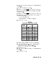
Table 3-1. Allowable Current Capacity Of The Wire
AWG
Stranding1
22
(7230)
22
(7230)
18 (19230)
16 (26230)
22
(7230)
22 (19234)
18 (19230)
18 (19230)
16 (26230)
14 (41230)
12 (65230)
10 (105230)
Rated Temp. Curr.
Voltage Rating Capacity
UL
Style
CSA
Type
80 C
90 C
90 C
90 C
105C
105C
105C
105C
105C
105C
105C
105C
1061 VW-1
1569 VW-1
1569 VW-1
1569 VW-1
1015 VW-1
1015 VW-1
1015 VW-1
1015 VW-1
1015 VW-1
1015 VW-1
1015 VW-1
1015 VW-1
SRPVC
TR64
TR64
TR64
TEW
TEW
TEW
TEW
TEW
TEW
TEW
TEW
300V
300V
300V
300V
600V
600V
600V
600V
600V
600V
600V
600V
TOC
TOC
TOC
TOC
TOC
TOC
TOC
2.6A
2.6A
7.2A
9.9A
3.6A
3.8A
9.9A
9.9A
13.5A
21.3A
33.8A
54.6A
TOC = Tin Overcoat (formerly BT, bunch tinned)
1 Number
of strand
2
conductor size (AWG)
When laced wires are used, the current capacity values listed in
Table 3-1 must be reduced by the following percentages.
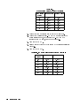
Table 3-2. Current Capacity Reducing Rate
Numbers Reducing
Rate
2 wires
3 wires
4 wires
5 wires
94%
89%
83%
76%
Current capacity determined from the percentages above Table 3-2
presumes equal current distribution between wires.
Operation Procedure and Examples
3-17
Inductance
Measurements
This section describes a practical example for an inductance
measurement, at 20A DC current, using a 490H ferrite-cored
inductor as the DUT, so that you can quickly learn the basic
operation of the 4284A combined with an 42841A.
The basic procedure for this measurement is the same as for the
\Basic Measurement Procedure" described previously. A ferrite-cored
inductor will be measured under the following conditions.
Sample (DUT) : 490H ferrite-cored inductor
(Agilent Part Number 9140-1358)
Measurement Conditions
Function
: Ls-Rs
Frequency
: 100kHz
Test Signal Level : 1V (constant)
DC bias
: 20A
Integration Time : Long
Cable Length
: 1m
Short Correction : ON
1. Turn the 4284A and 42841A on.
2. Setup the 4284A measurement conditions by modifying values and
settings in the elds on the MEAS DISPLAY page and the MEAS
SETUP page.
a. Move the cursor to the FUNC eld.
Figure 3-7. Moving Cursor to the FUNC Field
3-18
Operation Procedure and Examples
b. Press the more x/6 softkey three times and press the
softkey to choose the Ls-Rs function.
NNNNNNNNNNNNNNNNNNNNNNNNNN
NNNNNNNNNNNNNNNNN
Ls-Rs
NNNNNNNNNNNNNNNN
Figure 3-8. Softkey Path To The
Ls-Rs
softkey
c. Move the cursor to the FREQ eld. The default measurement
frequency, 1.00000kHz, is displayed in this eld.
Figure 3-9. Moving Cursor to the FREQ Field
d. Press the 415, 405, 405 keys. 100 will be displayed on the system
message line, and the softkey labels will change to the available
units. Press the kHz softkey. 100.000kHz is displayed on the
FREQ eld.
NNNNNNNNNNN
Operation Procedure and Examples
3-19
Note
Measurement frequency can also be changed using the INCR and
DECR softkeys displayed when the cursor is moved to the FREQ
eld.
NNNNNNNNNNNNNN
NNNNNNNNNNNNNN
Figure 3-10. Measurement Frequency Value Entry
e. Move the cursor to the BIAS eld. The current DC bias level,
0.00 mA, is displayed in this eld.
Figure 3-11. Moving Cursor to the BIAS Field
f. Press the 425 and 405 keys. 20 will be displayed on the system
message line, and the softkey labels are changed to the
available units. Press the A softkey. 20.00A is displayed on the
BIAS eld.
NNNNN
3-20
Operation Procedure and Examples
Figure 3-12.
NNNNN
Bias Current Value Entry (before pressing the
A
softkey)
g. Move the cursor to the INTEG eld. The default integration
mode, MED, is displayed in this eld and the SHORT , MED , and
LONG softkeys will be displayed.
h. Press the LONG softkey to select the LONG integration mode.
NNNNNNNNNNNNNNNNN
NNNNNNNNNNN
NNNNNNNNNNNNNN
NNNNNNNNNNNNNN
Figure 3-13. Moving Cursor to the INTEG Field
Operation Procedure and Examples
3-21
Note
These measurement conditions can also be set from the MEAS
SETUP page displayed when the 4MEAS SETUP5 menukey is pressed.
The setting operation on the MEAS SETUP page is the same as in
the preceding steps (a) to (h).
i. Press the 4MEAS SETUP5 menukey. The MEAS SETUP page is
displayed.
Figure 3-14. Select Measurement Setup Page
j. Move the cursor to the ALC eld. The default status of the
ALC function, OFF, is displayed on this eld, and the ON and
the OFF softkeys are displayed.
NNNNNNNN
NNNNNNNNNNN
Figure 3-15. Move Cursor to the ALC field.
3-22
Operation Procedure and Examples
k. Press the ON softkey to enable automatic leveling for the test
signal voltage. An asterisk is displayed in the left most position
of the LEVEL eld.
NNNNNNNN
Figure 3-16. To Enable the Automatic Level Control Function
3. Perform a SHORT correction data measurement.
To compensate measurement errors due to residual impedance
of the 42842A/B, a SHORT correction is required. Press the
4MEAS SETUP5 menukey and the CORRECTION softkey. The
CORRECTION page is displayed.
a. Move the cursor to the CABLE eld. The current cable length
is displayed on this eld and the 0 m , 1 m , 2 m , and 4 m
softkeys are displayed.
b. Press the 1 m softkey to set the cable length to 1 m.
NNNNNNNNNNNNNNNNNNNNNNNNNNNNNNNN
NNNNNNNNNNN
NNNNNNNNNNN
NNNNNNNNNNN
NNNNNNNNNNN
NNNNNNNNNNN
Operation Procedure and Examples
3-23
Figure 3-17. Set Cable Length
c. Connect a shorting bar to the 42842A/B to set up the SHORT
condition as shown in Figure 3-18.
Figure 3-18. Connecting the Furnished Shorting Bar
d. Move the cursor to the SHORT eld. The
MEAS SHORT softkeys is displayed.
NNNNNNNNNNNNNNNNNNNNNNNNNNNNNNNN
3-24
Operation Procedure and Examples
ON , OFF ,
NNNNNNNN
NNNNNNNNNNN
and
Figure 3-19. Move the Cursor to the SHORT Field
e. Press the MEAS SHORT softkey to perform the SHORT
correction data measurement. It will take approximately 90
seconds. Wait until the 4284A beeps and displays the message
SHORT measurement completed. on the system message line.
f. Press the ON softkey to set the SHORT correction function to
ON.
NNNNNNNNNNNNNNNNNNNNNNNNNNNNNNNN
NNNNNNNN
Figure 3-20.
System Message When the Short Measurement is Completed
Note
When you measure at a spot frequency, spot SHORT correction
function is useful. Correction data at the spot frequency of a
maximum of three frequency points you specify can be obtained
quickly and easily.
Operation Procedure and Examples
3-25
4. Connect the DUT to the test xture.
Connect the DUT to the 42842A/B measurement terminals and
close the test xture protective cover.
5. Enable the DC bias output.
Press the 4DC BIAS5 key on the 4284A front panel to turn the DC
bias on. The DC bias on/o LED indicators of the 4284A and
42841A will come ON simultaneously.
6. Perform the measurement.
Press the 4DISP FORMAT5 menukey.
Measurements are triggered continuously by the internal trigger
and the measured Ls and Rs values of the ferrite-cored inductor
are displayed in large characters as shown in Figure 3-21.
Figure 3-21. Ferrite-Cored Inductor Measurement Results
7. Disable the DC bias output.
When the measurement is nished, turn the DC bias o by
pressing the 4DC BIAS5 key to prevent the DUT from overheating.
The DC bias on/o LED indicators of the 4284A and 42841A will
go o simultaneously.
3-26
Operation Procedure and Examples
DC Bias Current List
Sweep
The 4284A's LIST SWEEP function allows setting of a maximum of
ten frequency, test signal level, or DC bias voltage points. Also, DC
bias current can be set when using with the 42841A. Figure 3-22
shows the measurement example of the DC bias current list sweep.
Figure 3-22. DC Bias Current List Sweep Result
Note
In the manual trigger mode, list sweep function holds the last
measurement condition until it is changed. Set last point to the 0A
to prevent the DUT from overheating.
Operation Procedure and Examples
3-27
Remote Control
This section provides information about the remote control capability
of the 42841A.
The 42841A is fully controlled by the 4284A with Option 002 Bias
Current Interface. The 4284A converts GPIB commands into control
commands for the 42841A and outputs them to the 42841A via the
bias current interface.
Error Messages for the 42841A used with the 4284A, refer to the
4284A Operation Manual, Appendix B, Error Message And System
Message .
Remote Control
Capability
When combined with the 42841A, all remote control capabilities
of the 4284A are available except for the limitations described
in \Operation Limitations" on page 3-1. For the remote control
capabilities of the 4284A, refer to the 4284A Operation Manual,
Section 7, Remote Control , and Section 8, Command Reference .
The following nine GPIB commands are available to control the
42841A.
BIAS:STATe ON(1)
BIAS:STATe OFF(0)
BIAS:STATe?
BIAS:CURRent <value>
BIAS:CURRent?
BIAS:CURRent MAX
BIAS:CURRent? MAX
BIAS:CURRent MIN
BIAS:CURRent? MIN
3-28
Operation Procedure and Examples
Turn the DC current bias on.
Turn the DC current bias o.
Query the current DC current bias status.
Set the DC current bias value.
Query the current DC current bias value.
Set the maximum DC current bias value.
Query the maximum DC current bias
value.
Set the minimum DC current bias value.
Query the minimum DC current bias value.
Sample Program
10
20
30
40
50
60
70
80
90
100
110
120
130
140
150
160
170
180
190
200
A typical DC biased measurement program is listed below. This
program applies the DC bias from 1A to 20A in 1A steps and
displays measurement result. This program is written in HP 9000
series 200/300 BASIC statements.
Here, it assumed that the 4284A's GPIB address is 717.
Lcr=717
OUTPUT Lcr;"*RST;*CLS"
OUTPUT Lcr;"CORR:LENG 1;METH SING"
OUTPUT Lcr;"CORR:OPEN:STAT OFF"
OUTPUT Lcr;"CORR:LOAD:STAT OFF"
OUTPUT Lcr;"SPOT1:STAT OFF"
OUTPUT Lcr;"SPOT2:STAT OFF"
OUTPUT Lcr;"SPOT3:STAT OFF"
OUTPUT Lcr;"FUNC:IMP LSRS;:APER LONG"
OUTPUT Lcr;"INIT:CONT ON;:TRIG:SOUR BUS"
OUTPUT Lcr;"BIAS:STAT ON"
FOR I=1 TO 20
OUTPUT Lcr;"BIAS:CURR ";VAL$(I)
OUTPUT Lcr;"*TRG"
ENTER Lcr;A,B,C
PRINT I,A,B
NEXT I
OUTPUT Lcr;"BIAS:STAT OFF"
LOCAL Lcr
END
Initialize the 4284A.
Enable the DC bias.
Measure from 1A to 20A in 1A steps.
Set the bias current value.
Trigger the instrument.
Get result.
Display result.
Disable the DC bias when nished.
Release the 4284A.
Operation Procedure and Examples
3-29
4
General Information
Introduction
Serial Number
This section describes specications, supplemental performance
characteristics, storage/repackaging, and other general information
about the 42841A.
Agilent Technologies uses a two-section, nine character serial number
which is stamped on the serial number plate (Figure 4-1) attached
to the instrument's rear panel. The rst four digits and a letter are
the serial number prex, and the last ve digits are the sux. The
letter placed between the two sections identies the country where
the instrument was manufactured. The prex is the same for all
identical instruments; it changes only when a change is made to the
instrument. The sux, however, is assigned sequentially and is
dierent for each instrument. The contents of this manual applies to
instruments with the serial number prex(es) listed under the serial
numbers on the title page.
Figure 4-1. Serial Number Plate
An instrument manufactured after the printing of this manual may
have a serial number prex which indicates that the instrument is
dierent from those described in this manual. The manual for this
new instrument may be accompanied by a yellow Manual Change
supplement or have a dierent manual part number. This sheet
contains \change information" that explains how to adapt the
manual to the newer instruments.
In addition to change information, the supplement may contain
information for correcting errors (Errata) in the manual. To keep this
manual as current and accurate as possible, Agilent Technologies
recommends that you periodically request the latest Manual Changes
supplement. The supplement for this manual is identied by this
General Information
4-1
manual's printing date and its part number, both of which appear on
the manual's title page. Complimentary copies of the supplement are
available from Agilent Technologies. If the serial prex or number of
an instrument is lower than that on the title page of this manual, see
.
For information concerning, a serial number prex that is not listed
on the title page or in the Manual Change supplement, contact the
nearest Agilent Technologies oce.
Specifications
DC Bias Current Output
The complete 42841A specications are described below. These
specications are the performance standards or limits against which
the 42841A is tested. When shipped from the factory, the 42841A
meets the specications listed in this section. The specication test
procedures are covered in Chapter 5.
The 42841A covers from 0.00A to 20.0A in three ranges.
Table 4-1. DC Bias Current Accuracy
Range
0.00A to 1.00A
1.1A to 5.0A
5.1A to 20.0A
Resolution Accuracy1
0.01A
0.1A
0.1A
1% + 5mA
2%
3%
6(% of setting + oset current)
Specied for an ambient temperature range of 23C65C. Add the
following temperature induced setting error for the temperature
range of 0C to 55C.
1
Figure 4-2. Temperature Induced Setting Error
4-2
General Information
Output Voltage
Depends on the DC resistance of Device Under Test. Maximum
voltage is shown in Figure 4-3
Figure 4-3. DC Bias Output Range
Applicable Test Signal
Interface
Other Options
Furnished Accessories
4284A or 4285A test signal voltage setting is 0.5V to 2Vrms.
Digital interface for connection to an Option 002 of 4284A or an
Option 002 of 4285A.
Option 907:
Option 908:
Option 909:
Front Handle Kit
Rack Mount Kit
Rack Flange and Handle Kit
Bias Current Interface Agilent Part Number 42841-61640
Cable
Operation Manual
Agilent Part Number 42841-90000
Power Cord
Depends on the country where the 42841A is
being used. Refer to Figure 1-1.
General Information
4-3
Test Fixtures
Other Accessories
Line Voltage
Line Frequency
42842A Bias Current Test Fixture (for 4284A 20A system)
42842B Bias Current Test Fixture (for 4284A 40A system)
42842C Bias Current Test Fixture (for 4285A)
42843A Bias Current Cable (for 40A system)
100, 120, 220V 6 10%, 240V +5%-10%
47 to 66Hz
Power Consumption
600VA max.
Operating Temperature
0 C to 55 C
Operating Humidity
Operating Altitude
Dimensions
Weight
Supplemental
Performance
Characteristics
42841A Measurement
Accuracy (used for
4284A)
RH 95% at 40C
0 m to 2000 m
426(W) by 177(H) by 498(D) (mm)
18 kg
The 42841A measurement accuracy represent characteristics are
listed below. Supplemental performance characteristics are not
specications, but are typical characteristics included as supplemental
information for the operator.
The measurement range of the 4284A is limited to 10
and 100
when used with the 42841A and 42842A/B. Measurement accuracy
of inductance(L), impedance(jZj), series resistance (Equivalent Series
Resistance; Rs ), D, and when the 42841A is used with the 4284A
and 42842A/B are as follows:
jj
L and Z Accuracy : Ae (for L accuracy; Dx
Ae
Where,
4-4
General Information
= A0 + A1 [% of
reading ]
0.1)
A0
A1
Dx
: L and jZj accuracy of the 4284A when used with the
42841A. A0 is determined from the measurement
accuracy lines shown in Figure 4-4. Select the proper
accuracy line in Figure 4-5. When the test signal voltage
level is not on the three points listed in Figure 4-5, linear
interpolation is required from the nearest two
measurement accuracy points to determine the
measurement accuracy to be applied.
: L and jZj additional error of the 42842A/B.
: Measured D value.
p
When Dx > 0.1, multiply A1 by 1 + Dx2 for L accuracy.
Figure 4-4. 4284A Accuracy
Figure 4-5. 4284A Basic Accuracy Line Selection Chart
General Information
4-5
D Accuracy : De (Dx
De
Where,
0.1)
Ae
= 100
: L and jZj measurement accuracy
: Measured D value.
Ae
Dx
When Dx > 0.1, multiply De by (1 + Dx ) for D accuracy.
Accuracy :
e
e
2 Ae []
= 180
2 100
Rs (Equivalent Series Resistance) Accuracy : Rse (Dx
Rse
Where,
f
Lx
De
4-6
General Information
= 2f Lx 2 De[
]
: Measurement frequency [Hz]
: Measured inductance [H]
: D measurement accuracy
0.1)
Additional Error Caused
by 42842A/B
The 42841A measurement accuracy represents the tolerance
of additional errors to the 4284A's accuracy and applies at the
42842A/B's measurement terminals when all the following conditions
are satised,
4284A Integration mode : LONG
Test signal voltage setting : 1Vrms
Test cable : 16048A
Test cable length : 1 m
SHORT compensation has been performed.
Ambient temperature : 23C 6 5C
Dissipation factor of the DUT is less than 1
<
jj
L and jZj accuracy, A1, is read from the gures listed in Table 4-2
L and
Z Additional Error (for L accuracy; Dx
0.1)
depending on the measurement conditions and the system
conguration.
Where,
Dx
: D measurement accuracy
p
When 0.1 Dx < 1, multiply A1 by 1 + Dx2 for L accuracy.
For ambient temperature range of 5C to 45C, add the temperature
inducede error given in Figure 4-8 of Figure 4-11, to A1 value.
Table 4-2. Accuracy Chart Selection Table
20A Conguration 40A Conguration
Inductance L-D,Rs
Impedance jZj-
Temperature Induced Error
Note
Figure 4-7
Figure 4-8
Figure 4-9
Figure 4-10
Figure 4-11
Figure 4-12
The error represented by the following equations has already been
factored into the error model in \42841A Measurement Accuracy
(used for 4284A)". So, the operator does not have to make these
caluculate when only the system accuracy is required.
General Information
4-7
D Additional Error : D1 ( Dx
<
0.1 )
D1 Additional error is given as,
D1
Where,
A1
= 100
: Measured D value
Dx
When 0.1 Dx < 1, multiply D1 by 1 + Dx for D accuracy.
Additional Error :
Where,
D1
1
1
= tan01 D1[ ]
: D Additional error
Rs (Equivalent Series Resistance) Additional Error : Rs1 (Dx
<
0.1)
Rs additional error, Rs1 is given as,
Rs1 = 2f Lx 2 D1
Where,
Lx
D1
Dx
f
Note
4-8
General Information
:
:
:
:
Measured inductance [H]
D additional error
Measured D value
Measurement frequency
The upper 2% accuracy lines at frequencies above 1kHz can be
gotten by drawing line at double the inductance values of the upper
1% lines.
Figure 4-6. Inductance measurement accuracy of 42841A ( 20A Configuration )
General Information
4-9
Figure 4-7. Impedance measurement accuracy of 42841A ( 20A Configuration )
Figure 4-8. Temperature additional error of 42841A ( 20A Configuration)
4-10
General Information
Figure 4-9. Inductance measurement error of 42841A ( 40A Configuration )
General Information
4-11
Figure 4-10. Impedance measurement accuracy of 42841A ( 40A Configuration )
Figure 4-11. Temperature additional error of 42841A ( 40A Configuration )
4-12
General Information
Measurement Accuracy
(used for 4285A)
Measurement accuracy of inductance (L), impedance (jZj), series
resistance (Equivalent Series Resistance: Rs ), D, and when the
42841A is used with an 4285A and 42842C are as follows:
L and
jj
Z Accuracy : Ae (for L accuracy; Dx
0.1 or Qx
10)
= A0 + A1 + A2 + A3 [% of reading ]
Where,
: L and jZj accuracy of the 4285A when 1 m cable is used [
0
Ae
A
A1
:
A2
:
A3
:
fm
Lx
Dx
:
:
:
% ]. Refer to the specications in 4285A Operation
Manual (Agilent Part Number 04285-90000).
L and jZj additional error of the 42842C [ % ]. Refer to
\42842C Additional Error".
L and jZj additional error caused by residuals of 42842C
[ % ];
2
= ( 40LnH
x + 2 2 fm 2 Lx ) 2 100
When SMD Test Fixture is used;
2
= ( 10LnH
x + 1:2 2 fm 2 Lx ) 2 100
Additional
error caused by SMD Test Fixture [ % ];
q
f
m
= 10
Measurement frequency [MHz ]
Measured inductance [ H ]
Measured D value
p
When Dx > 0.1, multiply Ae by 1 + Dx2 for L and jZj accuracy.
D Accuracy : De (Dx
De
Where,
Ae
Dx
0.1)
Ae
= 100
: L and jZj measurement accuracy
: Measured D value
When Dx > 0.1, multiply De by ( 1 + Dx ) for D accuracy.
General Information
4-13
Accuracy :
e
Ae
e
2 Ae [ ]
= 180
2 100
: L and jZj measurement accuracy
Rs (Equivalent Series Resistance) Accuracy : Re
Re
f
Lx
Ae
42842C Additional Error
4-14
General Information
p
Ae
+ 2 + 7 2 fm 2 1003 [
]
= 2f Lx 2 100
When an SMD Test Fixture is used:
Ae
Re = 2f Lx 2
100 + 0:005 [
]
Where,
: Measurement frequency [Hz ]
: Measured inductance [ H ]
: L and jZj measurement accuracy
The 42841A and 42842C additional error represents the tolerance of
additional error to the 4284A's accuracy and applies at the 42842C
measurement terminals when all the following conditions are satised.
4285A Integration mode : LONG
Test signal voltage setting : 0.5V to 2Vrms
Test cable : 16048A
Test cable length : 1 m
Cable Correction and SHORT compensation has been performed.
Ambient temperature : 0 to 45 C
Dissipation factor of the DUT is less than 1
Figure 4-12. Additional Inductance Error of the 42842C
General Information
4-15
Figure 4-13. Additional Impedance Error of the 42842C
4-16
General Information
jj
L and jZj additional error, A1 , is read from Figure 4-12 and
L and
Z Additional Error: A1
Figure 4-13 respectively.
L additional error applies when Dx (measured D value) < 0.1.
Note
The error represented by the following equations has already been
factored into the error model in \Measurement Accuracy (used for
4285A)". So, the operator does not have to make these caluculate
when only the system accuracy is required.
D Additional Error
When Dx (measured D value) < 0.1, D additional error, D1, is given
as follows,
D1
Where,
A1
A1
= 100
: L and jZj additional error
Additional Error :
1
additional error, 1 , is given as follows,
1 = tan01 D1 [ ]
Where,
D1
: D additional error
Rs (Equivalent Series Resistance) Additional Error : R1
When Dx (measured D value) < 0.1, Rs additional error, R1 , is given
as follows,
R1 = (2f Lx 2 D1 ) [
]
Where,
f
Lx
D1
: Measurement frequency [Hz ]
: Measured inductance [ H ]
: D additional error
General Information
4-17
Bias Current Settling
Time
Signal Voltage ALC
Operation Area
Measurement Error
Calculation Example
Typical time required for the bias current to reach 99% of setting
from zero amperes is given as
Bias current 1A: 1 s 2 Ibias + 0.6 s
Bias current 5A: 0.2 s 2 Ibias + 0.6 s
Bias current > 5A: 0.1 s 2 Ibias + 0.6 s
where, Ibias is the bias current setting in amperes.
ALC function of the 4284A is operational to 1Vrms on the 1A range
of the 42841A. On the other ranges, the available ALC operating
area varies depending on the applied current bias, the test frequency,
and the DUT's impedance.
This example calculates Ls -Rs measurement accuracy.
Measurement Conditions:
DUT:
10 mH
Test signal level:
1Vrms
Test frequency:
1kHz
Integration time:
LONG
Short compensation: Performed
DC current bias:
5A
Operating temperature: 28C
Inductance measurement accuracy Ae, and series resistance
(Equivalent Series Resistance) measurement accuracy Re of the HP
4284A when used with the 42841A are derived using the following
equations respectively.
Ae = A0 + A1
= R0 + R1
Where, A0 is L and jZj accuracy of the 4284A.
R 0 is Rs (ESR) accuracy of the 4284A.
A1 is L and jZj accuracy of the 42841A.
R 1 is Rs (ESR) accuracy of the 42841A.
Step 1:
Determine A0 and R0 of the 4284A when using with the HP
42841A.
Re
4-18
General Information
1. DUT's inductance is 10 mH, so the measurement impedance Zm
is
Z m = 2 fm L x
62:8 [
]
Where, fm is test frequency.
Lx is DUT's measured inductance value.
2. Determine measurement accuracy line from Figure 4-5 to be
applied to Figure 4-4.
Line D is selected from the operating temperature of 28C, and
test signal voltage of 1Vrms.
3. Find the impedance along the x axis.
4. Mark the intersection of the above two steps. Both axes are in
log format. Interpolation may be required.
5. Determine A0 by extrapolating horizontally to the vertical basic
accuracy axis.
A0 = 0:10
[%]
D0 =
A0
100
:10
= 0100
= 0:001
R 0 = (2 fLx 2 D 0 )
= (2 2 1000 2 0:01 2 0:001)
0:063 [
]
Step 2:
Determine the 42841A's additional error, L1.
1. Choose an accuracy chart from Table 4-2. Figure 4-6 is chosen
for the 20A conguration and Ls-Rs measurement.
2. Find the frequency along the X axis in Figure 4-6.
3. Find the Inductance along the Y axis in Figure 4-6.
4. Mark the intersection of above two steps. Both axis are in log
format. Interpolation may be required.
5. Determine L1. When a value falls at a boundary line, apply
the better value. Conrm the DC current bias applying to the
DUT. It must be less than the maximum DC current bias on
the marked area.
General Information
4-19
Test frequency = 1kHz, Lx = 10 mH, and DC current bias = 5A,
therefore:
L1 = 1
[%]
Step 3:
Determine the 42841A's temperature induced error, K 1, from
Figure 4-8, and derive R1 .
Operating temperature = 28C, therefore:
K1 = 0
[%]
From L1 and K 1
A1 = L 1 + K 1
= 1+0
= 1 [%]
D1 =
A1
100
1
= 100
= 0:01
Test frequency = 1kHz, Lx = 10 mH, and D 1 = 0.01 therefore:
R 1 = (2 fLx 2 D 1 )
= 2 2 1000 2 0:01 2 0:01
0:63 [
]
Therefore, the 4284A's measurement accuracy when used with the
42841A and 42842A/B is:
Ae = A0 + A1
= (0:1 + 1)
= 1:1 [%]
Re = R 0 + R 1
= (0:063 + 0:63)
= 0:693 [
]
4-20
General Information
Storage and
Repacking
Environment
This paragraph describes the environment for storing or shipping the
42841A, and how to repackage it for shipment when necessary.
The 42841A should be stored in a clean, dry environment. The
following environmental limitations apply for both storage and
shipment.
Temperature:
Humidity:
-20C to 60C
95% RH (at 40C)
To prevent condensation from taking place on the inside of the
42841A, protect the instrument against temperature extremes.
Original Packaging
Other Packaging
Containers packing materials identical to those used in factory
packaging are available through your closest Agilent Technologies.
For servicing, attach a tag indicating the service required, the
return address, the model number, and the full serial number. Mark
the container FRAGILE to help ensure careful handling. In any
correspondence, refer to the instrument by model number and its full
serial number.
The following general instructions should be used when repacking
with commercially available materials:
1. Wrap the 42841A in heavy paper or plastic. When shipping to a
Agilent Technologies sales oce or service center, attach a tag
indicating the service required, return address, model number, and
the full serial number.
2. Use a strong shipping container. A double-walled carton made of
at least 350 pound test material is adequate.
3. Use enough shock absorbing material (3 to 4 inch layer) around all
sides of the instrument to provide a rm cushion and to prevent
movement inside the container. Use cardboard to protect the front
panel.
4. Securely seal the shipping container.
5. Mark the shipping container
handling.
FRAGILE to help ensure careful
6. In any correspondence, refer to the 42841A by model number and
by its full serial number.
This ISM device complies with Canadian ICES-001.
Cet appareil ISM est conforme a la norme NMB-001 du Canada.
General Information
4-21
5
Performance Test
Introduction
Note
Note
Test Equipment
This section provides the test procedures used to be sure that the
42841A meets the specications listed in Chapter 4. All tests can be
performed without accessing the interior of the instrument.
Performance tests are used to perform incoming inspection and to be
sure that the 42841A is within its performance specications after
troubleshooting or adjustments have been performed.
If the performance tests show that the 42841A is not within
specications, check your test setup, then proceed to Adjustment or
Troubleshooting as required. The adjustment and troubleshooting
information are included in the 42841A Service Manual.
Allow the 42841A to warm up for a minimum of 5 minutes before
staring the performance test.
The performance tests are valid only when performance in an
ambient temperature of 23C 6 5 C.
The test Equipment required for the performance test is listed in
Table 5-1. Use only calibrated test equipment when performance
testing the 42841A.
If the recommended test Equipment is not available, Equipment with
specications equal to or surpassing those of the recommended test
equipment may be used.
Performance Test
5-1
Table 5-1. Recommended Test Equipment
Equipment
Requirement
Resistance Meter Range: up to 1
Accuracy: 6 0.5% at 50m
60.2% at 200m
60.05% at 1
DC Voltmeter Range: up to 1V
Accuracy: 60.05%
LCR Meter
No substitute
Recommended Model
3458A
1
3458A
1
4284A(opt. 002) or
4285A(opt. 002)
50m
Resistor No substitute
Agilent PN 42841-65100
200m
Resistor No substitute
Agilent PN 42841-65101
1
Resistor
No substitute
Agilent PN 42841-65102
Test Lead
Low thermal, banana to banana 11058A
5-2
Qty
1
1
1
1
2
Performance Test
Record
Record the results of the performance test in the Performance Test
Record, located at the end of this chapter. Keep a record of past test
results for comparison purpose to help showing any possible areas of
developing trouble.
Note
The test limit shown in the performance test does not consider the
measurement errors induced by the test equipment used. Be sure to
consider this when determining whether the 42841A meets its shown
specications or not.
Calculation Sheet
The Calculation Sheet is used to as an aid for recording raw
measurement data, and calculating the performance test result.
Photocopy the calculation sheet, and use it to calculate the test
result according to the performance test procedure.
Calibration Cycle
The 42841A requires periodic performance proof. How often you
verify performance depends on the operating and environmental
conditions. Check the 42841A using the performance test described
in this manual at least once a year. To reduce instrument down-time
and to insure best operation, perform preventive maintenance and
calibration at least twice a year.
Performance Test
This test makes be sure that the 42841A's DC Bias Current meets
specications. Table 5-2 lists the 42841A's DC Bias Current accuracy
specications. The accuracy is specied for an ambient temperature
range of 23C 6 5C.
DC Bias Current
Accuracy Test
Table 5-2. Bias Current Accuracy Specification
Current Range
Accuracy
0.00A to 1.00A 6(1%+5mA)
1.1A to 5.0A
62%
63%
5.1A to 20A
Test Equipment
Table 5-3 shows the recommended performance test equipment.
Table 5-3. Recommended Test Equipment
Equipment
Requirements
Recommended Model
DC Voltmeter Range: up to 1V, Accuracy: 60.05% 3458A
LCR Meter
No substitute
4284A (opt. 002) or
4285A (opt. 002)
50m
Resistor No substitute
Agilent PN 42841-65100
200m
Resistor No substitute
Agilent PN 42841-65101
1
Resistor
No substitute
Agilent PN 42841-65102
11058A
Test Lead
Low thermal, banana to banana
Note
Qty
1
1
1
1
1
1
When bias current is applied to the Resistor Box, the resistor box
heats and its resistance value changes. The Resistor Boxes are
designed to perform the DC Bias Current Accuracy Test, considering
the resistance value change caused by applying bias current. The
value of resistance changes for the 50m
, 200m
and 1
Resistor
Boxes are:
50m
Resistor Box: Resistance change=0.2% (Typical value, at
20A DC bias)
200m
Resistor Box: Resistance change=0.15% (Typical value, at
5A DC bias)
1
Resistor Box: Resistance change=0.05% (Typical value, at 1A
DC bias)
Performance Test
5-3
Procedure
Figure 5-1. Bias Current Accuracy Test Setup
Note
Note
1. Calibrate the 50m
, 200m
and 1
Resistor Boxes as described
in \Resistor Box Calibration"
Resistor Box Calibration must be performed each time the test is
performed
Step 2 and 3 is only required when the 4285A is used.
2. Press the 4CATALOG SYSTEM MENU5 key and the SYSTEM CONFIG
softkey to display the SYSTEM CONFIG page.
3. Move the cursor to the CONFIG eld, and press the I BIAS
softkey to enable the 4285A to control the 42841A.
4. Connect the LCR meter to the 42841A using the Bias Interface
Cable.
5. Cycle the LCR meter's power OFF and ON to initialize it.
6. Set the Multimeter as follows.
(Settings for the 3458A)
Measurement Function:
DCV
Measurement Range:
Auto
Guard:
OPEN
7. Connect the 1
Resistor Box to the 42841A's output.
8. Connect the Resister Box's V-MONITOR HI terminal to
the terminal to the Multimeter's HI Input, and connect the
V-MONITOR LO terminal to the LO Input, as shown in
Figure 5-1.
9. Turn the 42841A ON.
NNNNNNNNNNNNNNNNNNNNNNNNNNNNNNNNNNNNNNNNN
NNNNNNNNNNNNNNNNNNNN
5-4
Performance Test
10. Perform steps 11 through 15 for all the DC bias settings listed in
Table 5-4.
11. Set the DC bias using the LCR meter.
12. Press the LCR meter's 4DC BIAS5 key to turn the DC bias ON.
13. Record the Multimeter reading on the Calculation Sheet using 5
signicant digits.
14. Press the LCR meter's 4DC BIAS5 key to turn the DC bias OFF.
15. Calculate the DC bias current, and conrm that the value is
within the test limits.
DC Bias Current is given as:
(Multimeter reading) 4 (Resistor Box cal. value)
16. Turn the 42841A OFF.
Table 5-4.
1A Range Bias Current Accuracy Test Limit
Bias Current Minimum Limit Maximum Limit
Setting
0A
10mA
100mA
200mA
300mA
500mA
700mA
900mA
1A
-5.0mA
4.9mA
94.0mA
193.0mA
292.0mA
490.0mA
688.0mA
886.0mA
0.985A
5.0mA
15.1mA
106.0mA
207.0mA
308.0mA
510.0mA
712.0mA
914.0mA
1.015A
17. Connect the 200m
Resistor Box to the 42841A's output.
18. Connect the Resister Box's V-MONITOR HI terminal to the
Multimeter's HI Input, and connect the V-MINITOR LO
terminal to the LO Input, as shown in Figure 5-1.
19. Turn the 42841A ON.
20. Perform steps 11 through 15 for all the DC bias settings listed in
Table 5-5.
21. Turn the 42841A OFF.
Performance Test
5-5
Table 5-5.
5A Range Bias Current Accuracy Test Limit
Bias Current Minimum Limit Maximum Limit
Setting
1.1A
2A
3A
4A
5A
1.078A
1.960A
2.940A
3.920A
4.900A
1.122A
2.040A
3.060A
4.080A
5.100A
22. Connect the 50m
Resistor Box to the 42841A's output.
23. Connect the Resistor Box's V-MONITOR HI terminal to the
Multimeter's HI Input, and connect the V-MONITOR LO
terminal to the LO Input, as shown in Figure 5-1.
24. Turn the 42841A ON.
25. Perform steps 11 through 15 for all the DC bias settings listed in
Table 5-6.
26. Turn the 42841A OFF.
Table 5-6. 20A Range Bias Current Accuracy Test Limit
Bias Current Minimum Limit Maximum Limit
Setting
5.1A
8A
10A
15A
17A
20A
5-6
Performance Test
4.947A
7.760A
9.70A
14.55A
16.49A
19.40A
5.253A
8.240A
10.30A
15.45A
17.51A
20.60A
Resistor Box
Calibration
Test Equipment
This section tells how to calibrate the 50m
, 200m
and 1
Resistor
Boxes.
Table 5-7 lists the recommended performance test equipment.
Table 5-7. Recommended Test Equipment
Equipment
Requirement
Recommended Model Qty
3458A
Resistance Meter Range: up to 1
Accuracy: 60.5% at 50m
60.2% at 200m
0.05% at 1
Low thermal, banana to banana 11058A
Test Lead
1
2
Procedure
Figure 5-2. Resistor Box Calibration Setup
1. Set the Multimeter as follows:
(Setting for the 3458A)
Measurement Function:
4-wire ohms
Measurement Range:
Auto
Integration Time:
100 PLCs
Auto Zero:
ON
Oset Compensation:
ON
2. Connect the 50m
Resistor Box to the Multimeter's 4-wire sense input, as shown in Figure 5-2
3. Record the Multimeter reading on the Calculation Sheet using 5
signicant digits for the Resistor Box calibration value.
4. Connect the 200m
resistor Box to the Multimeter's 4-wire sense input as shown in Figure 5-2.
Performance Test
5-7
5. Record the Multimeter reading on the Calculation Sheet using 5
signicant digits for the Resistor Box calibration value.
6. Connect the 1
Resistor Box to the Multimeter's 4-wire sense
input as shown in Figure 5-2.
7. Record the Multimeter reading on the Calculation Sheet using 5
signicant digits for the Resistor Box Calibration value.
5-8
Performance Test
Calicuation Sheet
1A Range DC Bias Current Accuracy Test
1 Resistor Box Calibration Value (a=) [
Bias Current
Setting
Multimeter Reading
(b=)
0A
10 mA
100mA
200mA
300mA
500mA
700mA
900mA
1A
]
Test Result
(b4a=)
[mV]
[mV]
[mV]
[mV]
[mV]
[mV]
[mV]
[mV]
[mV]
[mA]
[mA]
[mA]
[mA]
[mA]
[mA]
[mA]
[mA]
[mA]
5A Range DC Bias Current Accuracy Test
200m
Resistor Box Calibration Value (a=) [
Bias Current
Setting
1.1A
2A
3A
4A
5A
Multimeter Reading
(b=)
]
Test Result
(b4a=)
[V]
[V]
[V]
[V]
[V]
[A]
[A]
[A]
[A]
[A]
Performance Test
5-9
20A Range DC Bias Current Accuracy Test
50m
Resistor Box Calibration Value (a=) [
Bias Current
Setting
5.1A
8A
10A
15A
17A
20A
5-10
Performance Test
Multimeter Reading
(b)=
]
Test Result
(b4a=)
[V]
[V]
[V]
[V]
[V]
[V]
[A]
[A]
[A]
[A]
[A]
[A]
Performance Test
Record
HEWLETT-PACKARD 42841A BIAS CURRENT SOURCE
Tested by
Serial Number
Test Date
DC Bias Current Accuracy Test
Bias Current
Setting
Minimum Limit
0A
10mA
100mA
200mA
300mA
500mA
700mA
900mA
1A
1.1A
2A
3A
4A
5A
5.1A
8A
10A
15A
17A
20A
05.0mA
4.9mA
94.0mA
193.0mA
292.0mA
490.0mA
688.0mA
886.0mA
0.985A
1.078A
1.960A
2.940A
3.920A
4.900A
4.947A
7.760A
9.70A
14.55A
16.49A
19.40A
Maximum Limit
Test Result
[mA]
[mA]
[mA]
[mA]
[mA]
[mA]
[mA]
[mA]
[A]
[A]
[A]
[A]
[A]
[A]
[A]
[A]
[A]
[A]
[A]
[A]
5.0mA
15.1mA
106.0mA
207.0mA
308.0mA
510.0mA
712.0mA
914.0mA
1.015A
1.122A
2.040A
3.060A
4.080A
5.100A
5.253A
8.240A
10.30A
15.45A
17.51A
20.60A
Performance Test
5-11
A
Manual Changes
Introduction
Manual Changes
This appendix contains the information required to adapt this
manual to earlier versions or congurations of the 42841A than the
current printing date of this manual. The information is this manual
applies directly to 42841A Bias Current Source whose serial number
prex is listed on the title page of this manual.
To adapt this manual to your 42841A, refer to Table A-1, and make
all the manual changes listed opposite your instrument's serial
number.
Instruments manufactured after the printing of this manual may be
dierent from those documented in this manual. Later instrument
versions will be documented in a manual changes suplement that
will accompany the manual shipped with that instrument. If your
instrument serial number is not listed on the title page of this
manual or in Table A-1, it may be documented in yellow MANUAL
CHANGES supplement.
For additional information on serial number coverage, refer to \Serial
Number" in Chapter 4.
Table A-1. Manual Changes by Serial Number
Serial Prex
or Number
Make Manual Changes
There are no earlier congurations than the printing
date of this manual.
Manual Changes
A-1
REGIONAL SALES AND SUPPORT OFFICES
For more information about Agilent Technologies test and measurement products, applications, services, and
for a current sales office listing, visit our web site: http://www.agilent.com/find/tmdir. You can also contact one
of the following centers and ask for a test and measurement sales representative.
11/29/99
United States:
Agilent Technologies
Test and Measurement Call Center
P.O.Box 4026
Englewood, CO 80155-4026
(tel) 1 800 452 4844
Canada:
Agilent Technologies Canada Inc.
5150 Spectrum Way
Mississauga, Ontario
L4W 5G1
(tel) 1 877 894 4414
Europe:
Agilent Technologies
Test & Measurement
European Marketing Organization
P.O.Box 999
1180 AZ Amstelveen
The Netherlands
(tel) (31 20) 547 9999
Japan:
Agilent Technologies Japan Ltd.
Call Center
9-1, Takakura-Cho, Hachioji-Shi,
Tokyo 192-8510, Japan
(tel) (81) 426 56 7832
(fax) (81) 426 56 7840
Latin America:
Agilent Technologies
Latin American Region Headquarters
5200 Blue Lagoon Drive, Suite #950
Miami, Florida 33126
U.S.A.
(tel) (305) 267 4245
(fax) (305) 267 4286
Australia/New Zealand:
Agilent Technologies Australia Pty Ltd
347 Burwood Highway
Forest Hill, Victoria 3131
(tel) 1-800 629 485 (Australia)
(fax) (61 3) 9272 0749
(tel) 0 800 738 378 (New Zealand)
(fax) (64 4) 802 6881
Asia Pacific:
Agilent Technologies
24/F, Cityplaza One, 1111 King’s Road,
Taikoo Shing, Hong Kong
(tel) (852)-3197-7777
(fax) (852)-2506-9284