1
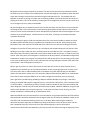
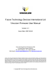
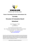
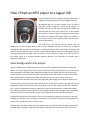
How I fitted an MP3 player to a Jaguar XJ8
This document describes a method of fitting an MP3 player to
a Jaguar XJ8 using the controls from the original head unit.
My 2000 MY XJ8 has a 6 disc CD stacker, but I still find on
long trips I need to change cd’s, and as the cd changer is in
the boot, this can be a real pain if the boot is fully loaded. So I
started looking for other ways to play music. It was essential
that whatever method I choose, the original head unit had to
be retained to maintain the original look of the interior. It
also had to make use of the steering wheel controls, which I
could not do without.
Figure 1 XJ8 HU with MP3 player fitted
The head unit in the XJ8 was built by Alpine, and was
designed to fit into the Jaguar dash as well as to be integrated into the car electronics. It featured
AM/FM/LW radio with RDS and Traffic Alert, a cassette tape player and 6 stack Alpine cd changer, with
speed sensitive automatic volume control. It also featured integrated Phone and Navigation systems.
Steering wheels buttons allowed control of volume as well as selection of tape or cd tracks and cd’s in
the stacker. Some or all of these features would be difficult if not impossible to maintain with a
replacement head unit.
Some background to this project.
My initial thoughts for the MP3 source was to use an iPod or my 80GB Vosonic VP6320i storage unit,
which I use to store digital photos when I travel, this device will also play MP3 files. OK, so I had a device
that played MP3’s and had an audio (headphone) output, but the Jag HU does not have an Aux input.
Another problem I could see with this approach was where to put the Vosonic, or iPod for that matter,
while travelling. Also it meant having a lead connecting it to the HU, which meant I had to find
somewhere for the connector which was out of sight. Not good enough, there had to be another way.
The CD stacker in the boot communicates with the HU via a cable which contains +12V, ground, Left and
Right audio and two communication lines, the protocol used on these communication lines is called AiNet. Ai-Net was developed by Alpine to replace the earlier communication bus, called M-Bus. M-Bus
was used in the Jaguar XJ6 and a number of other vehicles. Despite what you might read on the WWW
M-Bus and Ai-Net are not compatible, neither in the hardware or the communication protocol.
Simply disconnecting the Ai-Net cable from the CDC and feeding the audio from the player to the Left
and Right lines did not work. The audio lines into the HU are muted unless communication between the
HU and CDC is established via the Ai-Net protocol.
I did however have some success with this method; I built a circuit which, upon seeing the presence of
the MP3 player, switched ( using solid state switches) the audio lines to the HU from the CDC, to the
MP3 player while leaving the data lines connected. The HU still saw the CDC connected and unmuted
the audio lines so the output from the MP3 player was heard through the cars speakers. When the MP3
player was removed, the audio from the CDC was again switched to the HU. The problem with this
approach is the CDC is playing a CD while you are listening to MP3, it cannot be heard of course but it is
playing all the same. This can be solved by removing the CD cartridge from the CDC, but this results in an
error message on the HU, totally unacceptable.
My next thoughts were to expand on that first circuit and also switch the data lines to a microcontroller
emulating the CDC. The microcontroller could then be programmed to accept input from the HU and
convert it to the correct commands to control the Mp3 player (iPod) that was connected. Again the issue
of where to put the MP3 player, I still did not like it in the cabin, so leaving it in the boot seemed an
acceptable alternative.
Prior to starting this project I had searched the Internet for a commercial product to attach an iPod to
the Alpine radio and found there were products for the M-Bus but not Ai-Net, while searching I had
found there was a CDC emulator for M-Bus but not Ai-Net. So the only way was to design one myself.
I bought a HU and CDC off e-bay and set it up on the bench and started looking at the Ai-Net bus. After
building a circuit that I could look at the communication on the Ai-Net bus with, I very quickly realized
that none of the information I had found on the internet about Ai-Net was correct, so I had to start from
scratch. After many hours of investigation I worked out the Ai-Net protocol, and decoded enough of the
commands to enable me to program an emulator that made the HU think it was controlling a CDC, when
it fact it was an MP3 player or iPod, so all I had to do now was fully debug the emulator code, add a few
more features I was thinking about, and that’s it.
Before I got any further my Cousin asked me to do a trip with him across the Great Victoria Desert (
1100 Kms across the desert) in his Land Rover Defender. As this trip was going to be for 3 weeks, most
of it where there was no radio broadcast and his Land Rover only had radio cassette, we decided to
replace the radio with a modern unit. This unit had a USB port and would play MP3’s from a USB thumb
drive. After 3 weeks using the USB drive on this radio I thought it was brilliant, the only way to go.
After I got home I started looking at adding a USB port and MP3 decoder to my design, it was while
looking for suitable USB interface integrated circuits, I came across a device from FTDI in Scotland called
a Vinculum VNC1L , it looked like just what I wanted, I ordered a couple of chips from their website and
while doing that I noticed they had a ready built MP3 player module, called the VMUSIC2, using this chip
and the same decoder chip I was planning to use, I ordered one of these as well, thinking, as it was
already assembled, it would speed up my development work.
When the VMUSIC2 arrived I connected it to a microcontroller using sample code from the FTDI website,
and confirmed it worked as advertised. At that stage the plan was to mount the VMUSIC2 module in the
case that I had mounted the switching circuit into, in the boot. While measuring the module to
determine the cutout required, the module was sitting on the bench in front of the HU, and I noticed
that it appeared to be very close to the size of the cassette opening in the HU. A few quick
measurements confirmed it was indeed very close to the same size. After removing the tape player from
the HU, and trimming down the VMUSIC2 module with a modeling knife, I found it to be a perfect fit. I
removed the cassette door from the HU and pushed the module into the opening, a nice snug fit and it
would be easy enough to fabricate a bracket to secure it to two of the original tape player mounting
brackets.
While fitting the VMUSIC module to the HU front panel, I was thinking about how I could use the
module as is instead of as a development tool. I knew the connector on the HU main board for the tape
player mechanism had to have pins connecting the audio from the tape heads to the main board and it
would be no problem connecting the audio output from the VMUSIC2 to these pins and pressing the
tape button on the HU would allow the audio from the VMUSIC to heard in the car speakers. I connected
the audio to the pins on the connector, turned the HU on and pressed the tape button, the HU screen
still showed radio and the sound from the speakers was from the radio. Hmmm obviously the HU knows
there is no tape mechanism; I suspected this would be the case.
As luck would have it the tape player mechanism had an Alpine part number stamped on it, GR75S620. I
started searching and came up with a service manual for Alpine GR75 series tape mechanism. I ordered
and duly downloaded the manual, it did not cover this particular model, but one of the mechanisms it
did cover looked very similar to the Jaguar unit. I started tracing the pins on the Jaguar unit and
comparing them to the manual, while they both used a 20 pin connector, the pins on the Jag unit did not
tie up with the manual. After a bit more investigating it turned out both connectors had the same
functions on the pins, but, the pins on the Jaguar connector were numbered in the reverse order to the
Alpine. There are 4 pins on the connector that the HU uses to see if a tape is loaded and running, two of
these go to switches on the tape mechanism, one of these tells the HU a tape has been loaded the other
tells it weather the tape is paused or playing. The other two pins each have a square wave generated by
the reel pulses in the tape mechanism to tell the HU the tape is running. The rest of the pins contain
power and control signals from the HU to tell the tape what to do.
I programmed a microcontroller to generate two pulse trains of the right frequency to simulate the reels
turning, and also supply the correct logic levels to the HU so it would think a tape had been loaded. After
connecting this controller and pressing the tape button, the HU screen displayed TAPE LOADING but
after a short time displayed TAPE EJECT. Not quite what I was hoping for, but I was on the right track. I
would now have to work out how the mechanism worked and what the HU was looking for and write a
program to emulate this behavior. By connecting an oscilloscope to the control lines on the tape
mechanism, and going through all the functions of the mechanism, I was able to establish what
waveforms and signal levels the mechanism and HU generated. I then wrote routines to emulate the
operation of the mechanical mechanism and send the right signals to the HU, and also take the control
signals from the HU, decode and then translate them into commands for the VMUSIC2 so that it is
controlled by the buttons on the HU. These routines were then added to a much modified version of the
VMUSIC2 sample program from FTDI, to form the complete firmware for the microcontroller. A printed
circuit board was then designed to plug into the tape mechanism socket in the HU, this board forms the
interface between the VMUSIC2 module and the HU.
The full operation of the tape mechanism is described in Appendix1.
MP3 Player operation.
To begin playing MP3’s, insert the usb drive into the socket in the front of the HU, the screen will display
“TAPE LOADING” a short time later the display will change to “TAPE SIDE 1” and the first track will start
playing. To remove the usb drive first press the tape eject button, the screen will say “TAPE EJECT” when
the LED on the VMUSIC stops flashing the usb drive can be removed. DO NOT remove drive without first
ejecting, doing so may corrupt data on the drive. Reinserting the drive will start playback from the first
track again. If the Ignition is switched off and the usb drive is left in, playback will recommence from the
point the ignition was turned off. Current drain in this mode is very small, but it is recommended if the
vehicle is to be left standing for several weeks the USB drive be ejected before turning off the ignition.
While playing MP3’s, pressing the CD button changes to the CD changer and the radio button to the
radio, pressing the tape button then resumes MP3 playback where it left off.
The FF button goes forward one track in the current folder, the FR button goes back one track in the
current folder. The side select button (button 4) changes to the next folder on the USB disk. If the side
button is pressed again after 2 seconds but within 5 seconds, then the play mode changes from
sequential to random mode, the same sequence again goes back to sequential mode and so on. The
steering wheel controls can also be used to perform the above functions.