1
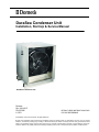
DuraSea Condenser Unit
Installation, Start-Up & Service Manual
DuraSea Condenser Unit
Dometic
Rev. 20141217
PN 337982
L-3153
RETAIN THESE INSTRUCTIONS FOR
FUTURE REFERENCE
COPYRIGHT © 2013-2014 Dometic. All Rights Reserved.
No part of this publication may be reproduced, translated, stored in a retrieval system, or transmitted in any form or by any means
electronic, mechanical, photocopying, recording or otherwise without prior written consent by Dometic. Every precaution has been
taken in the preparation of this manual to ensure its accuracy. However, Dometic Marine assumes no responsibility for errors and
omission. Neither is any liability assumed for damages resulting from the use of this product and information contained herein.
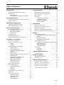
Table of Contents
INTRODUCTION . . . . . . . . . . . . . . . . . . . . . . . . . . . . . . . 1
SYSTEM START-UP . . . . . . . . . . . . . . . . . . . . . . . . . . . 15
READ THIS MANUAL BEFORE PROCEEDING . . . . . . . . . 1
REFRIGERANT CHARGING GUIDELINES . . . . . . . . . . . 15
HOW IT WORKS . . . . . . . . . . . . . . . . . . . . . . . . . . . . . 1
Basic Principles . . . . . . . . . . . . . . . . . . . . . . . . 1
The Importance of Outside Air Temperature . . 1
SYSTEM CHECK . . . . . . . . . . . . . . . . . . . . . . . . . . . . 16
SAFETY INSTRUCTIONS . . . . . . . . . . . . . . . . . . . . . . . 1
RECOGNIZE SAFETY SYMBOLS, WORDS AND LABELS . 1
SAFETY GUIDELINES . . . . . . . . . . . . . . . . . . . . . . . . . 1
UNPACKING AND INSPECTION . . . . . . . . . . . . . . . . . . 2
R-410A QUICK REFERENCE GUIDE . . . . . . . . . . . . . . 2
MODEL NUMBER NOMENCLATURE . . . . . . . . . . . . . . . . 2
INSTALLATION GUIDELINES . . . . . . . . . . . . . . . . . . . . 3
IMPORTANT SAFETY CONSIDERATIONS . . . . . . . . . . . .
Avoid Harmful Vapors . . . . . . . . . . . . . . . . . . . .
Electrical Shock Hazard . . . . . . . . . . . . . . . . . .
Other Hazards . . . . . . . . . . . . . . . . . . . . . . . . .
3
3
3
4
TOOLS REQUIRED . . . . . . . . . . . . . . . . . . . . . . . . . . . 4
CODES AND REGULATIONS . . . . . . . . . . . . . . . . . . . . . 4
CHECK UNIT ELECTRICAL CHARACTERISTICS . . . . . . . 4
PLACEMENT OF THE SYSTEM . . . . . . . . . . . . . . . . . . 4
INSTALLATION CLEARANCES . . . . . . . . . . . . . . . . . . . . 5
RIGGING AND MOUNTING THE UNIT . . . . . . . . . . . . . . . 7
Rigging . . . . . . . . . . . . . . . . . . . . . . . . . . . . . . . 7
Mounting . . . . . . . . . . . . . . . . . . . . . . . . . . . . . . 7
REFRIGERANT PIPING CONNECTIONS . . . . . . . . . . . . . 7
Copper Tubing . . . . . . . . . . . . . . . . . . . . . . . . . 7
Provide Safety Relief . . . . . . . . . . . . . . . . . . . . 7
Determine Refrigerant Line Sizes . . . . . . . . . . . 7
Liquid Lift . . . . . . . . . . . . . . . . . . . . . . . . . . . . . 9
Suction Riser . . . . . . . . . . . . . . . . . . . . . . . . . . 9
Multiple Evaporators On Single Condenser . . . 9
Install Filter Drier . . . . . . . . . . . . . . . . . . . . . . . 10
Install Liquid Line Solenoid Valve . . . . . . . . . . 10
Selecting an Accumulator . . . . . . . . . . . . . . . . 10
Make Piping Connections . . . . . . . . . . . . . . . . 10
Insulate Suction Lines . . . . . . . . . . . . . . . . . . . 10
Routing of Liquid Line . . . . . . . . . . . . . . . . . . . 10
SERVICE VALVE OPERATION . . . . . . . . . . . . . . . . . . . 10
REPLACEMENT/RETROFIT . . . . . . . . . . . . . . . . . . . . .
Existing evaporator coil . . . . . . . . . . . . . . . . . .
Acid Test . . . . . . . . . . . . . . . . . . . . . . . . . . . . .
Installation . . . . . . . . . . . . . . . . . . . . . . . . . . . .
10
11
11
11
PRELIMINARY REFRIGERANT CHARGE . . . . . . . . . . . . 15
START UNIT . . . . . . . . . . . . . . . . . . . . . . . . . . . . . . .
Compressor & Fan Rotation . . . . . . . . . . . . . .
Compressor Overload . . . . . . . . . . . . . . . . . . .
Final Charge Adjustment . . . . . . . . . . . . . . . . .
System Operation . . . . . . . . . . . . . . . . . . . . . .
16
16
17
17
18
MAINTENANCE . . . . . . . . . . . . . . . . . . . . . . . . . . . . . . 19
QUARTERLY INSPECTION
(AND 30 DAYS AFTER INITIAL START) . . . . . . . . . . . . . 19
SEASONAL MAINTENANCE . . . . . . . . . . . . . . . . . . . . . 19
ROUTINE CLEANING OF CONDENSER COILS . . . . . . . . 19
ROUTINE CLEANING & PROTECTION OF CABINET . . . . 19
SERVICE . . . . . . . . . . . . . . . . . . . . . . . . . . . . . . . . . . . . 20
REFRIGERATION SYSTEM . . . . . . . . . . . . . . . . . . . . . 20
Servicing Units on Roofs/Decks With Synthetic
Materials . . . . . . . . . . . . . . . . . . . . . . . . . . . . . 20
Liquid Line Filter Drier . . . . . . . . . . . . . . . . . . . 20
Field Refrigerant Access Ports . . . . . . . . . . . . 20
COMPRESSOR PROTECTION . . . . . . . . . . . . . . . . . . . 20
Compressor Over-Temperature Protection (IP) 20
Low-Pressure Switch . . . . . . . . . . . . . . . . . . . . 20
High-Pressure Switch . . . . . . . . . . . . . . . . . . . 20
Low-Ambient Option . . . . . . . . . . . . . . . . . . . . 20
LUBRICATION . . . . . . . . . . . . . . . . . . . . . . . . . . . . . . 20
Fan Motors . . . . . . . . . . . . . . . . . . . . . . . . . . . 20
Compressor . . . . . . . . . . . . . . . . . . . . . . . . . . . 20
GENERAL TROUBLESHOOTING . . . . . . . . . . . . . . . . 21
TROUBLESHOOTING . . . . . . . . . . . . . . . . . . . . . . . . . 21
START-UP CHECKLIST . . . . . . . . . . . . . . . . . . . . . . . . 23
PRELIMINARY INFORMATION . . . . . . . . . . . . . . . . . . . 23
PRE-START-UP . . . . . . . . . . . . . . . . . . . . . . . . . . . . 23
OWNERS LIMITED WARRANTY . . . . . . . . . . . . . . . . . 25
SECTION I - WHAT’S COVERED . . . . . . . . . . . . . . . . . 25
SECTION II - WHAT’S NOT COVERED . . . . . . . . . . . . . 25
SECTION III - COVERAGE PERIOD . . . . . . . . . . . . . . . 26
SECTION IV - GETTING SERVICE . . . . . . . . . . . . . . . . 26
TABLE OF WARRANTY PERIODS . . . . . . . . . . . . . . . . . 27
PRESSURE TEST AND LEAK CHECKING . . . . . . . . . . . 11
EVACUATION . . . . . . . . . . . . . . . . . . . . . . . . . . . . . . 13
ELECTRICAL CONNECTIONS . . . . . . . . . . . . . . . . . . .
Field Power Supply . . . . . . . . . . . . . . . . . . . . .
Field Control Wiring . . . . . . . . . . . . . . . . . . . .
Thermostat . . . . . . . . . . . . . . . . . . . . . . . . . . .
24VAC Controls . . . . . . . . . . . . . . . . . . . . . . .
13
13
13
14
14
L-3153
DuraSea Condenser Installation, Start-Up & Service Manual
Read This Manual Before Proceeding
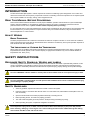
INTRODUCTION
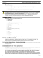
The Dometic DuraSea Split System is a direct-expansion air-cooled air conditioning system designed for use in marine and
other harsh environments. Its two primary components consist of a condensing unit and an evaporator unit. A complete system
also requires installation of control(s), ducting, and a refrigerant line-set.
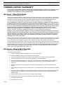
READ THIS MANUAL BEFORE PROCEEDING
This manual contains essential information to ensure proper installation, operation and maintenance of your DuraSea Split
System. Improper installation or misunderstood operating procedures can result in unsatisfactory performance and/or
premature failure of these units, so please read this manual completely before proceeding.
It is very important that you read and understand the contents of this manual before using the equipment, and it should be kept
for future reference. If you have questions or require assistance with your DuraSea Condenser, call your Dometic Marine
Service Department at +1 954-973-2477.
HOW IT WORKS
BASIC PRINCIPLES
The basic principle behind an air conditioner is the transfer of heat from one place to another. In an air-cooled air conditioner,
heat is removed from the inside cabin air and transferred to the outside air. The efficiency of the system operation depends on
both outside air and cabin temperatures.
THE IMPORTANCE
OF
OUTSIDE AIR TEMPERATURE
When cooling, the air conditioner will operate most efficiently in outside air temperatures below 100°F (38°C). At higher air
temperatures the unit will operate, but at a reduced capacity. A high-pressure shutdown may occur at outside ambient air
temperatures near 130°F (54°C).
SAFETY INSTRUCTIONS
RECOGNIZE SAFETY SYMBOLS, WORDS
AND
LABELS
The following symbols and labels are used throughout this manual to indicate immediate or potential safety hazards. it is the
owner’s and installer’s responsibility to read and comply with all safety information and instructions accompanying these
symbols. Failure to heed safety information increases the risk of personal injury, property damage, and/or product damage.
WARNING
The word “WARNING” indicates hazards or unsafe practices which COULD result in severe personal injury or death.
CAUTION
The word “CAUTION” indicates hazards or unsafe practices which COULD result in minor or moderate personal injury,
product damage, or property damage.
SAFETY GUIDELINES
1.
Allow only qualified, experienced technicians to install or service this system.
2.
Install the system in accordance with all local codes. If no local codes exist, follow National Codes (NEC in the U.S.,
CEC in Canada).
3.
Open the electrical disconnect switch(es) before electrically connecting the unit.
4.
Before operating the unit, be certain it is properly grounded.
5.
The units contain refrigerant gas under pressure. Avoid puncturing or breaking any tubing.
6.
Before operating the system, complete the refrigerant connections.
WARNING
To avoid personal injury, shock, or death, ensure the electrical disconnect switch(es) is (are) in the OFF position
before installing, modifying, or servicing the unit. Lock out and tag the switch with a suitable warning label. Wiring
must conform with NEC or CEC and all local codes.
L-3153
1
R-410A Quick Reference Guide
DuraSea Condenser Installation, Start-Up & Service Manual
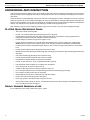
UNPACKING AND INSPECTION
Units are securely packed in shipping crates. Upon arrival, carefully check all items against the packing list to ensure all cartons
were received and correct equipment was received. Always keep the unit in the "up" orientation as indicated by the arrows on
each carton.
Check the cartons for external damage, removing the units from the packaging if necessary. If damage is found, file a request in
writing for inspection by the carrier agent immediately. The carrier is responsible for making prompt inspection of damage and
for a thorough investigation of each claim. The distributor or manufacturer will not accept claims from dealers for transportation
damage. If no damage is found, carefully remove all shipping material and properly dispose of it.
After unpacking, keep the units as upright as possible. Laying a unit on its side or top could cause equipment damage.
R-410A QUICK REFERENCE GUIDE
•
This system uses R-410A refrigerant.
•
R-410A is an environmentally safe hydrofluorocarbon (HFC) refrigerant.
•
R-410A refrigerant operates at 50-70% higher pressures than R-22. Ensure that the servicing equipment and
replacement components used are designed to operate with R-410A.
•
R-410A refrigerant cylinders are light maroon (pink) in color.
•
R-410A refrigerant cylinders have a dip tube which allows liquid to flow out of the cylinder in an upright position.
NOTE: Recovery cylinder service pressure rating must be 400 psig (2758 kPa), DOT RBA400 or DOT BW400.
•
R-410A systems should be charged with liquid refrigerant. Use a commercial type metering device in the manifold
hose.
•
R-410A requires a different set of gauges than those used for R-22.
•
Manifold sets should be 800 psig (5516 kPa) high side and 250 psig (1724 kPa) low side with 550 psig (3792 kPa) low
side retard.
•
Use hoses with 800 psig (5516 kPa) service-pressure rating.
•
R-410A requires matched evaporator and condenser systems.
•
Leak detectors should be designed to detect HFC refrigerant.
•
R-410A, as with other HFCs, is only compatible with POE or PVE oils.
•
POE oils absorb moisture rapidly. Do not expose oil to atmosphere.
•
Vacuum pumps will not remove moisture from oil.
•
A liquid line filter dryer listed for R-410A is required on every unit.
•
Do not use liquid line filter dryers with rated working pressures less than 600 psig (4137 kPa).
•
Do not install a suction line filter dryer in a liquid line.
•
Wrap all filter dryers and service valves with wet cloth when brazing.
•
Do NOT use an R-22 thermal expansion valve (TXV).
•
Never open system to atmosphere while it is under a vacuum.
•
When system must be opened for service, evacuate then break vacuum with dry nitrogen and replace filter dryers.
•
Do not vent R-410A into the atmosphere.
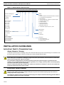
MODEL NUMBER NOMENCLATURE
For an explanation of the model numbers see Figure 1, page 3.
2
L-3153
DuraSea Condenser Installation, Start-Up & Service Manual
Important Safety Considerations
Figure 1: Model Number Nomenclature
1 2 3
D C A
ͲͲͲͲͲͲͲͲ
4 5 6
0 3 6
ͲͲͲͲͲͲͲͲͲͲ
7
A
8 9 10 11 12 13 14 15
4 6 6 3 C 0 A A
ͲͲͲͲͲͲͲͲͲͲͲͲͲͲͲ
DuraSeaCondensingUnit
RefrigerantType
A=R410A
B=R417A
NominalTonnage
030=2.5Tons
036=3Tons
048=4Tons
060=5Tons
072=6Tons
090=7.5Tons
120=10Tons
ControlType
A=NoneͲusewith24VACThermostat
Q=QControl
Voltage
2361=230V/60/1
2251=220V/50/1
2363=208Ͳ230V/60/3
4663=460V/60/3
3853=380V/50/3
Options
A=None
B=Nema4xelectricBox&heatshrunkelectricconnections
C=LowambientFanCyclingControl
D=PhaseMonitor
E=ValveFanSide(VFS)Ͳstandardon7.5/10tonmodels
F=VariableFrequencyDrive
G=CrankcaseHeater
H=SuctionAccumulator
I=Reservedforfutureuse
J=Reservedforfutureuse
K=CombinationofoptionsB,C,D,G,andH
DesignRevision
A=InitialRev
NotUsed
0=NotUsed
CoilOptions
A=AlFin/CopperTube
B=EͲCoatAlFin/CopperTube
C=CopperFin/Tube
INSTALLATION GUIDELINES
IMPORTANT SAFETY CONSIDERATIONS
AVOID HARMFUL VAPORS
Consideration should be given to installing a trap in the condensate drain line(s) so that normal discharge of condensate can fill
the trap and prevent the ingress of carbon monoxide (CO) or other potentially harmful vapors.
WARNING
Never install your air conditioner in the bilge or engine room areas. Ensure that the selected location is sealed from
direct access to bilge and/or engine room vapors.
Do not terminate condensate drain line within three feet (1 meter) of any outlet of engine or generator exhaust
systems, nor in a compartment housing an engine or generator, nor in a bilge, unless the drain is connected properly
to a sealed condensate or shower sump pump.
Failure to comply may allow bilge or engine room vapors to mix with the air conditioner’s return air and contaminate
living areas which may result in injury or death.
ELECTRICAL SHOCK HAZARD
WARNING
Electrical shock hazard. Disconnect voltage at main panel or power source before opening any cover. Failure to
comply may result in injury or death.
To minimize the hazard of electrical shock and personal injury, this component must be effectively grounded. Refer to
the installation guidelines for further information.
L-3153
3
DuraSea Condenser Installation, Start-Up & Service Manual
Tools Required
OTHER HAZARDS
Installation and servicing of this system can be hazardous due to system pressure and electrical components.
•
When working on this equipment, always observe precautions described in the literature, tags and labels attached to
the unit.
•
Follow all safety codes.
•
Wear safety glasses and work gloves and place a fire extinguisher close to the work area.
CAUTION
United States federal law prohibits the intentional release of refrigerant gases into the environment, including the R410A refrigerant used in this air conditioning system. Special care must be taken when installing, charging and
servicing Dometic equipment to prevent any loss of refrigerant.
Dometic does not recommend the practice of using refrigerant to purge air and moisture from the system at
installation. This formerly used practice of purging is in violation of United States federal law.
TOOLS REQUIRED
Before starting, make sure you have all of the following tools:
CODES
•
Standard tool box
•
Service wrench
•
Flaring tool
•
Refrigerant gauge manifold (rated for R-410A only)
•
Refrigerant tank (rated for R-410A only)
•
Nitrogen tank
•
Vacuum pump
•
Scale
•
Micron gauge
•
Electronic leak detector (rated for R-410A)
•
Drill/hole saw
•
Jig saw
•
Insulated tape
•
Duct tape
•
Electrical tape
•
Teflon tape
•
Hardware to secure unit, pump, grilles, and control panel
AND
REGULATIONS
This product is designed and manufactured to comply with national codes. Installation in accordance with such codes,
prevailing local codes/regulations, and National Electrical Code (NEC, U.S.A.) is the responsibility of the installer. The
manufacturer assumes no responsibility for equipment installed in violation of any codes or regulations.
CHECK UNIT ELECTRICAL CHARACTERISTICS
Confirm before installation of unit that voltage, amperage and circuit protection requirements listed on unit data plate agree with
power supply provided.
PLACEMENT OF THE SYSTEM
Selecting a good location for your air conditioner is the most important part of your preparations. Be sure to consider the size of
the area you are cooling, the air distribution needs, and the size of the unit you have chosen.
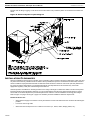
Keeping in mind that cool air falls, it is highly recommended that you locate the supply air grille as high as possible in the cabin.
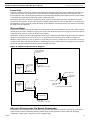
Plan all connections which must be made prior to starting installation, including ducting, grilles, copper line set, condensate
drain, electrical power connections, and location of control panel. See Figure 2 for general layout example.
Select a location for the condensing unit and its support system (pad, rails or other) that provides for the minimum clearances
required for safety. This includes the clearance to combustible surfaces, airflow clearance, wiring, refrigerant piping, and service
access below, around and above unit as specified in unit drawings. Check for possible overhead obstructions which may
4
L-3153
DuraSea Condenser Installation, Start-Up & Service Manual
Installation Clearances
interfere with unit lifting or rigging. Locate the unit so that the outdoor coil (condenser) airflow is unrestricted on all sides and
above.
Figure 2: General System Layout Diagram
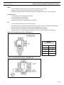
INSTALLATION CLEARANCES
Special considerations must be given to location of the condensing unit(s) in regard to structures, obstructions, other units, and
any other factors that may interfere with air circulation. Where possible, the top of the unit should be unobstructed, however if
vertical conditions require placement beneath an obstruction there should be a minimum of 30 inches (762 mm) between the
top of the unit and the obstruction(s). The specified dimensions meet requirements for air circulation only. Consult all
appropriate regulatory codes prior to determining final clearances.
Another important consideration in selecting location for the unit(s) is the angle to obstructions. Either coil side can be placed
toward the structure with appropriate clearance. It is not recommended for fan side to be placed towards structure. Service
access side of unit should be placed to provide adequate service clearance. Corner installations are strongly discouraged.
Refer to Figure 3 on page 6 and Figure 4, page 6 for mandatory minimum installation clearance requirements.
DO NOT locate the unit:
L-3153
•
Where fresh air supply to the outdoor coil may be restricted or when recirculation from the condenser fan discharge is
possible.
•
In a well or next to high walls.
•
Where the noise would prove to be a nuisance to the owner (i.e., salons, decks, sleeping cabins, etc.).
5
Installation Clearances
DuraSea Condenser Installation, Start-Up & Service Manual
AVOID:
•
Locations that permit water from higher level runoff and overhangs to fall onto the unit.
•
Direct tubing contact with water pipes, ductwork, floor joists, floors, and walls.
•
Suspending refrigerant tubing from structure with rigid wire or straps that would come in contact with tubing.
DO locate the unit:
•
To minimize the length of refrigerant piping required.
•
To provide adequate service clearances.
•
On a level surface or other sturdy platform.
•
Isolated from the structure to avoid transmission of vibrations.
•
Leave slack between structure and unit to absorb vibration.
DO:
•
When passing refrigerant tubes through the bulkhead, seal the opening with RTV or a pliable silicon-based caulk.
•
Ensure that the suction and liquid line tube diameters are appropriate for unit capacity.
•
Avoid unnecessary turns and bends by running refrigerant tubing as directly as possible.
•
In general, short runs of refrigerant piping are better than long runs. If practical, locate the unit accordingly.
Figure 3: Installation Clearance - DCA 24-72
METRIC
CONVERSION CHART
inches (")
cm
6
15
12
30
18
45
24
60
Figure 4: Installation Clearance - DCA 90-120
6
L-3153
DuraSea Condenser Installation, Start-Up & Service Manual
RIGGING
AND
MOUNTING
THE
Rigging and Mounting the Unit
UNIT
CAUTION
Unit Damage Hazard - Failure to follow this caution may result in equipment damage.
All panels and top must be in place when rigging or moving.
RIGGING
These units are designed for overhead rigging. Spreader bars or a field-provided H-style frame just above the top edge of unit
are required. All panels and top must be in place when rigging. As further protection for coil faces, plywood sheets may be
placed against the sides of the unit, behind cables. Run cables to a central suspension point so that the angle from the
horizontal is not less than 45 degrees. Raise and set the unit down carefully.
If it is necessary to move the unit into position, mount the unit on longitudinal rails, using a minimum of 3 rollers. Apply force to
the rails, not the unit. If the unit is to be skidded into position, place it on a large pad and drag it by the pad. Do not apply any
force to the unit. Raise from above to lift the unit from the rails or pad when unit is in its final position.
MOUNTING
After the unit is in position, remove all protective coverings. The condensing unit should be secured using mounting hardware
provided to level surface that is designed for the weight of the unit and torsion loads from the vessel's movement. Unit should be
mounted above the deck so it is unaffected by vessel washdown activity.
If mounted in area has debris and clippings, the mounting surface should extend a minimum of 6 inches (150 mm) beyond unit
cabinet. Install a gravel or other apron in front of condenser coil air inlet to prevent grass and foliage from obstructing airflow. If
vibration isolators are required for a particular installation, use the data in Table 2 on page 16 to make the proper selection.
REFRIGERANT PIPING CONNECTIONS
COPPER TUBING
Refrigeration-grade tubing is required to connect the refrigerant circuit from the evaporator to the condensing unit. You must use
tubing with the proper diameter and wall thickness specified for R-410A pressures.
Refrigerant tubing is normally soft drawn and nitrogen purged. All refrigerant lines should be capped to protect against moisture
and dust infiltration. Tubing should always be cut square keeping ends round and free from burrs. Clean the tubing to prevent
contamination.
Extreme care must be taken not to crush or kink any portion of either line set. Use proper tools for line bending, avoiding sharp
bends or kinks. Any kinked or crushed section must be replaced. There should be no vertical loops (oil traps) in the copper lines.
When using multiple evaporators, ensure that the fittings are sized correctly to allow correctly sized tubing to be connected to air
handler fittings and provide proper refrigerant flow to and from each air handler.
PROVIDE SAFETY RELIEF
If local codes dictate an additional safety relief device, purchase locally and install locally. Installation will require the recovery of
the factory shipping charge before the factory tubing can be cut and the supplemental relief device is installed.
DETERMINE REFRIGERANT LINE SIZES
Determine the linear length of interconnecting piping required between the outdoor unit and indoor unit (evaporator). Consider
and identify the arrangement of the tubing path (quantity and type of elbows in both lines), liquid line solenoid size, filter drier
and any other refrigeration specialties located in the liquid line. Refer to the indoor unit installation instructions for additional
details on refrigeration specialties devices.
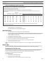
Select the recommended line sizes for DuraSea unit from Table 1 on page 8. These sizes are suitable for line lengths of 50 feet
(15.24 m) or less. If a run of more than 50 feet (15.24 m) is required, contact Dometic applications team for assistance.
L-3153
7
8
6000
2.0
1/2
7/8
3/8
3/4
25
80
460/60/3Y
12
15
414/506
84
290
6000
3.6
1/2
7/8
3/8
3/4
25
80
208Ͳ230/60/3'
30
40
197/253
84
310
208Ͳ230/60/3'
1/2
7/8
3/8
3/4
25
80
6000
3.6
12.7
120
DCA48D
48,000
460/60/3Y
15
20
414/506
84
310
1/2
7/8
3/8
3/4
25
80
6000
2.0
6.6
60
DCA48E
48,000
30
40
197/253
84
365
208Ͳ230/60/3'
1/2
7/8
3/8
7/8
35
120
6000
3.6
14.8
123
DCA60D
60,000
460/60/3Y
20
25
414/506
84
365
1/2
7/8
3/8
7/8
35
120
6000
2.0
7.4
70
DCA60E
60,000
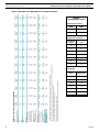
2
Recommendedlinesizesbasedonlinelengthlessthan50'.ConsultDometicforlongerlinelenghts.
WiresizeshouldbedeterminedinaccordancewithNationalElectricalCodes,Extensivewirerunsrequirelargerwiresizes
3
MustusetimeͲdelayfusesorHACRtypecircuitbreakersofthesizeasnoted
4
Soundlevelmeasuredfrom3ftawayfromCondensingunit
5
WeightforAluminumfincondensercoilwithcoating.
AlldatasubjecttochangeatDometic'sdiscretionintheinterestofproductimprovement
1
5
45
10.9
95
25
35
197/253
84
290
DCA36E
36,000
DCA36D
36,000
DURASeaCondensingUnitR410ASPECIFICATIONS
Model
NominalCooling(BTU/Hr)
Compressor
RLA
LRA
CondenserFan
CFM
MotorFLA
RefrigerationSystem
LiquidBaseValve(ID)
SuctionBaseValve(ID)
1
SuggestedLiqLine(OD)
1
SuggestedSuctLine(OD)
MaximumLift(Ft)
FactoryRefrigerantCharge
ElectricalData
PowerVolts/Hz/Phase
2
Min.CircuitAmpacity
3
Max.BreakerProtection
Min/MaxVolts
4
SoundLevel(dbA)
5
UnitWeight(lbs)
40
55
197/253
84
375
208Ͳ230/60/3'
1/2
7/8
1/2
7/8
35
120
6000
3.6
17.9
160
DCA72D
72,000
460/60/3Y
20
30
414/506
84
375
1/2
7/8
1/2
7/8
35
120
6000
2.0
8.9
87
DCA72E
72,000
50
70
197/253
84
475
208Ͳ230/60/3'
7/8
1Ͳ1/8
1/2
1Ͳ1/8
45
160
6000
3.6
25.5
235
DCA90D
90,000
460/60/3Y
25
30
414/506
84
475
7/8
1Ͳ1/8
1/2
1Ͳ1/8
45
160
6000
2.0
13.4
110
DCA90E
90,000
460/60/3Y
30
40
414/506
87
525
208Ͳ230/60/3'
55
75
197/253
87
525
7/8
1Ͳ1/8
5/8
1Ͳ3/8
45
150
10000
4.9
15.3
142
DCA120E
120,000
7/8
1Ͳ1/8
5/8
1Ͳ3/8
45
150
10000
8.5
31.3
267
DCA120D
120,000
Refrigerant Piping Connections
DuraSea Condenser Installation, Start-Up & Service Manual
Table 1: DuraSea Unit Refrigerant Line Specifications
METRIC
CONVERSION CHARTS
Condenser Fan Flow
CFM
CMM
6000
170
10000
283
Refrigeration System
Fractional
inches
mm
1/2
13
7/8
23
1-1/8
29
Feet
Meters
25
7.6
35
10.7
45
13.7
Unit Weight
Pounds
(lbs)
Kilograms
290
131.5
310
140.6
365
165.6
375
170.1
475
215.5
525
238.1
L-3153
DuraSea Condenser Installation, Start-Up & Service Manual
Refrigerant Piping Connections
LIQUID LIFT
A liquid lift condition exists when the outdoor unit is located below the indoor (evaporator) unit and liquid flows vertically up in a
portion of the liquid line. The vertical column of liquid reduces the available state point subcooling at the evaporator coil's
thermal expansion valve. This effect reduces the length of liquid lift (height of elevation) that a liquid line size can accommodate.
Longer linear tube lengths will also reduce the amount of liquid lift possible.
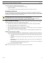
Mounting the evaporator coil above the condensing unit will require an inverted loop in the suction line adjacent or near the
connection to the evaporator. The top of the loop must be slightly higher than the top of the coil. See Table 1 for maximum liquid
lift capabilities. If cannot provide the required lift distance on this installation, relocate the outdoor unit to reduce the equivalent
line length or the lift requirement.
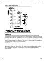
SUCTION RISER
A suction riser condition exists when the outdoor unit is located above the indoor (evaporator) unit and suction vapor must flow
vertically up to return to the compressor. Oil return is a concern when the suction tube size is too large to produce the minimum
refrigerant velocity to ensure oil return at minimum load conditions.
Mounting the condensing unit above the evaporator coil will require oil traps at equal intervals along the suction line. Install one
oil trap for a height difference of 15 to 25 feet (4.5 to 7.6 m) between indoor and outdoor units. Install two oil traps for a
difference of 26 to 50 feet (7.9 to 15.2 m), three for 51 to 100 feet (15.5 to 30.4 m), and four for 101 to 150 feet (30.7 to 45.7 m).
Consider suction speed riser (reduced tube size for vertical segment only) or double suction riser arrangement if the proposed
suction tube size does not provide necessary minimum flowrates for this riser.
Figure 5: Liquid and Suction Riser Diagram
LOOP TO PREVENT
DRAINAGE DURING
OFF CYCLE
EVAPORATOR
DURASEA
CONDENSING
UNIT
PITCH DOWN
TO OUTDOOR
UNIT
SUCTION
OIL TRAP
(SEE DETAIL OF OIL TRAP)
LINE
LIQUID LINE
45 DEG STREET ELL
LIQUID RISER
LONG RADIUS
STREET ELL
LOOP
45 DEG ELL
PITCH
SHORT RADIUS
STREET ELL
DURASEA
CONDENSING
UNIT
SUCTION
OIL TRAP CONSTRUCTION DETAIL
LINE
LIQUID LINE
SUCTION RISER
EVAPORATOR
OIL TRAP
(SEE DETAIL OF OIL TRAP)
MULTIPLE EVAPORATORS ON SINGLE CONDENSER
The DuraSea units are designated to be controlled by a single thermostat. When two evaporator coil units are connected to a
single condenser unit the evaporators plumbed in parallel. Piping to each evaporator must be of same size and piping
configuration must be similar in design and of same equivalent length.
L-3153
9
DuraSea Condenser Installation, Start-Up & Service Manual
Service Valve Operation
INSTALL FILTER DRIER
Every unit MUST have a filter drier in the liquid line.
Locate the filter drier(s) at the indoor unit, close to the evaporator coil's thermal expansion valve (TXV) inlets.
A R-410A rated filter drier is shipped in cartons near the base valves. Remove drier from packaging and install in the liquid
line(s) at the evaporator coil. Do not remove connection fitting plugs until ready to connect and braze the filter drier into the
liquid line position. Ensure the filter drier paint finish is intact after brazing. If the paint of the steel filter drier has been burned or
chipped, repaint or treat with rust preventative.
INSTALL LIQUID LINE SOLENOID VALVE
It is recommended that a solenoid valve be placed in the main liquid line between the condensing unit and the evaporator coil.
Locate the solenoid valve at the outlet end of the liquid line, near the evaporator coil connections, with flow direction arrow
pointed at the evaporator coil. A liquid line solenoid valve is required when the liquid line length exceeds 75 ft [23 m]. This valve
prevents refrigerant migration (which causes oil dilution) to the compressor during the off cycle, at low outdoor ambient
temperatures.
SELECTING
AN
ACCUMULATOR
Because all DuraSea models use scroll compressors, an accumulator is not required. Long refrigerant line applications may
require use of accumulator to protect compressor from excess charge. If an accumulator is to be added, check the accumulator
manufacturer's literature carefully for indication of its suitability for use with R-410A; look for minimum working pressure of 200
psig (1380 kPa). Select the accumulator first on the basis of its minimum capacity in tons to ensure oil return from the
accumulator, then on tube size or holding capacity.
CAUTION
Do not leave system open to atmosphere any longer than necessary for installation. The compressor PVE or POE oil
is extremely susceptible to moisture absorption and could cause compressor failure.
Ensure ends of tubing are sealed before and during installation.
MAKE PIPING CONNECTIONS
Piping connections at the DuraSea unit are base valves with stub tube extensions. Do not open the unit service valves until all
interconnecting tube brazing has been completed. The stub tube connections include 1/4-in SAE service fittings with Schrader
valve cores. Before making any brazed connections to the unit service valves, remove both Schrader valve caps and cores and
save for re-installation. Connect a source for nitrogen to one of these service fittings during tube brazing to prevent the
formation of copper oxides inside the tubes at brazed joints.
When brazing the field tubing to base valves, TXV valve, or filter drier, wrap the valves in wet rags to prevent overheating. Use
a brazing alloy of 5% minimum silver content. Do not use flux. Purge the refrigerant line with nitrogen during brazing to prevent
the formation of copper-oxide inside the refrigerant lines. After brazing quench the joints with water or a wet cloth to prevent
overheating of valves.
INSULATE SUCTION LINES
Insulation is necessary to prevent condensation from forming and dropping from the suction line. Apply Armaflex (or satisfactory
equivalent) closed-cell tubular insulation with ½" minimum wall thickness to all suction lines between evaporator coil connection
and unit's suction service valve. In severe hot and humid areas thicker wall insulation may be needed. Insulation must be
installed in a manner which protects tubing from damage and contamination.
ROUTING
OF
LIQUID LINE
The liquid line must be outside the suction line insulation. If part of the liquid line must run through an area that will be hotter
than 120°F (49°C), then that portion of the liquid line must be insulated. Be careful not to kink or dent the refrigerant lines.
Kinked or dented lines will cause poor performance or compressor damage.
SERVICE VALVE OPERATION
The DuraSea condensing unit is equipped with service valves to ensure safe handling of the high-pressure R-410A refrigerant.
The unit is shipped with the valve frontseated (downward position) to contain the factory charge in the unit. Gauge hoses can be
connected and disconnected without the presence of system pressure. The gauge port is isolated from the system if the stem is
backseated. The gauge ports have a standard core valve, which can be removed and replaced while the stem is backseated.
REPLACEMENT/RETROFIT
Replacement/retrofit installations require change-out of outdoor unit, metering device, and filter driers. Change-out of indoor coil
(evaporator) and interconnecting tubing is highly recommended.
10
L-3153
DuraSea Condenser Installation, Start-Up & Service Manual
EXISTING
Pressure Test and Leak Checking
EVAPORATOR COIL
If the existing evaporator coil is to be re-used, check with the coil manufacturer to verify the coil construction is suitable for
operation with the higher pressures of R-410A. Also determine if the existing TXV valve is compatible with R-410A, replace if
necessary. The minimum factory test pressure rating of evaporator must be 250 psig (1725 kPa). Existing coil will need to be
purged with Nitrogen to remove as much mineral oil as possible to eliminate cross contamination of oils.
ACID TEST
If the existing system is being replaced because of a compressor electrical failure, assume acid is in system. If system is being
replaced for any other reason, use an approved acid test kit to determine acid level. If even low levels of acid are detected,
install a 100 percent activated alumina suction-line filter drier in addition to the replacement liquid-line filter drier. Remove the
suction line filter drier after evaluation period of operation, with a maximum of 72 hours of operation. Recommendation: Install a
ball valve in the line at the filter location when installing a suction filter in the suction line.
Existing refrigeration piping - Reuse of existing refrigerant piping involves three issues: quality (strength) of existing tubing,
cleanliness and tube size. Inspect all tube segments and joints for signs of damage, corrosion or poor brazing. Flush the
interconnecting piping system with dry nitrogen to eliminate as much trace of mineral oil as possible.
INSTALLATION
1.
Remove the existing evaporator coil or fan coil and install the replacement coil when appropriate.
2.
Drain oil from low points and traps in suction line tubing (and hot gas bypass tubing if appropriate) and Evaporator if
they were not replaced. Removing oil from evaporator coil may require purging of the tubing with dry nitrogen.
3.
Unless indoor unit is equipped with a R-410A approved metering device, change the metering device to a thermal
expansion valve (TXV) designed for R-410A.
4.
Remove the existing outdoor unit. Install the new outdoor unit according to these installation instructions.
5.
Install a new field-supplied liquid-line filter drier at the indoor coil just upstream of the TXV or fix orifice metering device.
6.
If a suction line filter drier is also to be installed, install suction line drier downstream of suction line service valve at
condensing unit.
7.
Evacuate and charge the system according to the instructions in this installation manual.
8.
Operate the system for 10 hr. Monitor the pressure drop across the suction line filter drier. If pressure drop exceeds 3
psig (21 kPa), replace suction-line and liquid-line filter driers. Be sure to purge system with dry nitrogen and evacuate
when replacing filter driers. Continue to monitor the pressure drop across suction-line filter drier. Repeat filter changes
as necessary. Never leave suction-line filter drier in system longer than 72 hr (actual time).
CAUTION
Unit Damage Hazard - Failure to follow this caution may result in equipment damage or improper operation.
Never install a suction-line filter drier in the liquid line of an R-410A system.
PRESSURE TEST
AND
LEAK CHECKING
Once the refrigerant line-set connections are made a pressure test and a leak check of the system must be performed.
NOTE: The base valves on the unit are shipped in the frontseated position to retain the refrigerant in the condensing unit. These
valves must not be opened until the system is ready for operation.
Pressure Test
NOTE: It is sometimes assumed that any apparent leakage must originate in the equipment, but in reality leaks can also occur
in the gauge manifold and hoses. Before use, inspect the fittings on the manifold for tightness and replace any damaged hoses
or worn gaskets.
L-3153
1.
Before testing ensure both hand valves on the gauge manifold are closed relative to the center port (i.e., turned IN all
the way).
2.
Connect the high- and low-side hoses of your R-410A gauge manifold to the condenser base valves. IMPORTANT: Do
not open the unit service valves.
3.
Connect a dry nitrogen cylinder to the center port on the gauge manifold and set the regulator to a maximum pressure
of 500 psig (3447 kPa). IMPORTANT: Compressed air or CO2 should not be used as they can add moisture and ether
contaminates to the system! Refrigerant should never be used unless needed for electronic leak detection.
11
Pressure Test and Leak Checking
DuraSea Condenser Installation, Start-Up & Service Manual
WARNING
To avoid possible explosion, the line from the nitrogen cylinder must include a pressure regulator and a pressure
relief valve.
CAUTION
Never exceed 800 psi (5516 kPa) due to the possibility of rupturing hoses or line-set connections.
4.
Open the hand valve a minimal amount on the line coming from the nitrogen cylinder.
5.
Once the regulator on the nitrogen tank is set, open the high-pressure valve on the gauge manifold. Pressurize the
refrigerant lines and the evaporator(s) to 500 psig (3447 kPa). To reach 500 psig (3447 kPa), you may need to further
open the hand valve on the nitrogen cylinder.
6.
The needle(s) will rise as pressure enters the line set and evaporator(s). Once the point of the predetermined pressure
has been reached, close the gauge valve(s). Monitor the gauge reading(s) after the pressure has stabilized (should be
less than a minute). The pressure should be left in the system for a minimum of 15 minutes.
•
If the gauge pressure drops, there is a leak in the system. Refer to “Leak Check” on page 12 to determine the
location of the leak(s).
•
If the gauge pressure remains constant, close the valve on the nitrogen cylinder and disconnect it from the
gauge manifold. Proceed to “Evacuation” on page 13.
.
WARNING
When using high-pressure nitrogen in the system, wear safety glasses and gloves.
Secure the hose end to prevent injury to personnel or damage to property. Do not point the hose toward personnel or
property.
To prevent inhalation, the nitrogen should NOT be expelled into a confined space where personnel are working; the
work area should be well ventilated.
If the nitrogen is mixed with refrigerant , contact with an open flame or hot surface could create PHOSGENE GAS,
which can cause respiratory problems or death.
Leak Check
IMPORTANT: Do not use a vacuum as a leak detection technique as moisture could be drawn into the system.
•
A rapid drop in gauge pressure indicates a large leak or several small ones.
•
A slow drop in gauge pressure indicates small leak(s).
Open both gauge valves and pressurize the system again to maintain a positive pressure on the lines and evaporator while
checking for leaks. Use the following techniques to locate leaks.
•
Large leaks can often be detected by listening for a hissing sound or felt by placing your hand around the leaking
fitting. NOTE: If pipe insulation encases a leaking fitting, the escaping nitrogen can be forced down the insulation to a
remote location, giving a false indication of the leak location.
•
Apply a soap solution on all connections and joints. Bubbles indicate leaks, so mark these locations. Clean off the soap
solution when leak checking is complete.
CAUTION
Care must be taken to ensure soap solution does not ingress into a leaking fitting(s) and contaminate the system.
•
If the leaks cannot be located with the previous methods, an electronic leak detector should be used. For this
procedure, add a trace of R-410A refrigerant to the nitrogen in the system (if permitted by current EPA regulations).
NOTE: Ensure the electronic leak detector you use is capable of sensing HFC-type refrigerants.
Repeat the procedures above until all leaks are found and repaired. After repair, repeat the steps in “Pressure Test” on page 11.
When pressure-testing is completed, remove the nitrogen source at the outdoor unit service valves and re-install the two
Schrader valve cores. Torque the cores to 3 in-lbs (23-34 N-cm).
12
L-3153
DuraSea Condenser Installation, Start-Up & Service Manual
Evacuation
EVACUATION
If you have confirmed that the system maintains pressure, the line set and evaporator(s) are now ready for evacuation of the
nitrogen (or nitrogen/refrigerant mixture if an electronic leak detector was needed) from the system.
Release nitrogen from system.
Evacuation/Dehydration
Evacuate and dehydrate the connected refrigeration system, excluding the condensing unit, to 200 microns using a two-stage
vacuum pump attached to the service ports on the DuraSea service valves. Close the valve to the vacuum pump. Wait five
minutes, then check the pressure on the thermocouple vacuum gauge.
•
If the pressure is not more than 1000 microns, the system is leak-free and properly evacuated. Proceed to “Preliminary
Refrigerant Charge” on page 15.
•
If the pressure rises, but holds at about 2000 microns, moisture and noncondensibles are still present. Open the valve
to the vacuum pump, and continue evacuation until moisture is removed.
•
If the pressure rises above 5000 microns, a leak is present. Go back to “Pressure Test and Leak Checking” on
page 11. Close the valve to the thermocouple vacuum gauge. Close the valve to the vacuum pump. Shut off the pump.
ELECTRICAL CONNECTIONS
WARNING
Failure to follow this warning could result in personal injury or death.
Disconnect ALL power before servicing. Do not use gas piping as an electrical ground. Unit cabinet must have an
uninterrupted, unbroken electrical ground to minimize the possibility of personal injury if an electrical fault should
occur. Wiring must conform with NEC or CEC and all local electrical codes. Undersized wires could cause poor
equipment performance, equipment damage or fire.
WARNING
To avoid risk of fire or equipment damage, use copper conductors.
NOTE: Check all factory and field electrical connections for tightness. Field-supplied wiring shall conform with the limitations of
63°F (35°C) rise.
FIELD POWER SUPPLY
When installing units, provide a disconnect switch per NEC or CEC of adequate size.
Disconnect sizing data is provided on the unit informative plate. Locate on unit cabinet or within sight of the unit per national or
local codes. Do not cover unit data plate if mounting the disconnect on the unit cabinet.
All field wiring must comply with NEC and all local codes. Size wire based on MCA (Minimum Circuit Amps) on the unit data
plate. Connect wiring as per diagram located on unit.
Provide a ground-fault and short-circuit over-current protection device (fuse or breaker) per NEC Article 440 (or local codes).
Refer to unit informative data plate for MCB (Maximum Circuit Breaker) device size. Use HACR type circuit breakers or time
delay fuses to assure sufficient time delay to permit the compressor to start.
Voltage to compressor terminals during operation must be within voltage range indicated on unit nameplate. On 3-phase units,
voltages between phases must be balanced within 2% and the current within 10%. Operation on improper line voltage or
excessive phase imbalance constitutes abuse and may cause damage to electrical components. Such operation would
invalidate any applicable Dometic warranty.
FIELD CONTROL WIRING
DuraSea condenser uses a 24 VAC control voltage provided by air-handler. See Figure 6, page 14 for typical field control
connections and the unit's label diagram for field-supplied wiring details. Route control wires to the DuraSea unit through the
opening in unit's end panel to the connections 24VAC terminal block in the unit's control box.
Remainder of the system controls connection will vary according to the specific construction details of the indoor section (air
handler or packaged fan coil). Plan for field connections carefully and install control wiring correctly per the project plan.
L-3153
13
Electrical Connections
DuraSea Condenser Installation, Start-Up & Service Manual
Figure 6: 24VAC Wiring Diagram
THERMOSTAT
Install an approved accessory thermostat according to installation instructions included with the accessory. Locate the
thermostat accessory on a solid wall in the conditioned space to sense average temperature in accordance with the thermostat
installation instructions. DuraSea unit is a single-stage cooling unit. Use a single stage cooling thermostat. Select a thermostat
cable or equivalent single leads of different colors. Check the thermostat installation instructions for additional features which
might require additional conductors in the cable. For wire runs up to 50 ft. (15 m), use no. 18 AWG (American Wire Gage)
insulated wire (35 C minimum). For 50 to 75 ft. (15 to 23 m), use no. 16 AWG insulated wire (35 C minimum). For over 75 ft. (23
m), use no. 14 AWG insulated wire (35 C minimum). All wire sizes larger than no. 18 AWG cannot be directly connected to the
thermostat and will require a junction box and splice at the thermostat.
24VAC CONTROLS
Most commercial evaporator units include a transformer to provide 24VAC to provide power for thermostat. Dometic Marine
evaporators do not include a 24VAC output. In this instance the optional DuraSea 24VAC control box can be used to provide
24VAC power source to operate the DuraSea condenser fan, compressor, and indoor fan motor contactor (or control relay).
Additional devices may also include a liquid line solenoid valve, supplemental electric heater contactors or control relays and
other devices selected by system designer. Ensure the transformer is sized to handle additional power requirement of
supplemental devices.
14
L-3153
DuraSea Condenser Installation, Start-Up & Service Manual
Refrigerant Charging Guidelines
SYSTEM START-UP
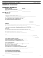
Use the “START-UP CHECKLIST” on page 23 to make notes as you go through the start-up procedures.
WARNING
Failure to follow this warning could result in personal injury, death, and/or equipment damage.
R-410A refrigerant systems operate at highter pressure than standard R-22 systems. Do not use R-22 service
equipment or components on R-410A refrigerant equipment.
REFRIGERANT CHARGING GUIDELINES
This unit is designed for use with R-410A refrigerant. Do not use any other refrigerant in this system. R-410A refrigerant is
provided in pink (rose) colored cylinders. These cylinders are available with and without dip tubes; cylinders with dip tubes will
have a label indicating this feature. For a cylinder with a dip tube, place the cylinder in the upright position (access valve at the
top) when removing liquid refrigerant for charging. For a cylinder without a dip tube, invert the cylinder (access valve on the
bottom) when removing liquid refrigerant.
Because R-410A refrigerant is a blend, it is strongly recommended that refrigerant always be removed from the cylinder as a
liquid. Admit liquid refrigerant into the system in the discharge line. If adding refrigerant into the suction line, use a commercial
metering/expansion device at the gauge manifold; remove liquid from the cylinder, pass it through the metering device at the
gauge set and then pass it into the suction line as a vapor. Do not remove R-410A refrigerant from the cylinder as a vapor.
WARNING
Refrigerants are heavier than air. They can “push out” the oxygen in your lungs or in any enclosed space. To avoid
possible death or difficulty breathing:
•
Never sniff a refrigerant.
•
Never purge refrigerant into an enclosed room or space. All refrigerants must, BY LAW, be reclaimed.
•
If an indoor leak is suspected, thoroughly ventilate the area before beginning work.
•
Liquid refrigerant can be very cold. To avoid possible frostbite or blindness, avoid contact and wear gloves and
goggles. If liquid refrigerant does contact your skin or eyes, get medical help immediately.
•
Never burn refrigerant, as poisonous gas will be produced.
•
Always follow EPA guidelines.
PRELIMINARY REFRIGERANT CHARGE
DuraSea condensing units are pre-charged with refrigerant as per unit data plate. Pre-charge amount is sufficient for
condensing unit plus 15 foot of lineset. Additional charge must be added for the evaporator and linesets longer than 15 feet (4.5
m). The amount of refrigerant to be added can be estimated from Table 2. See example below.
L-3153
1.
Purge gauge lines. Connect service gauge to base valve service ports.
2.
Add R-410A liquid refrigerant into the lineset through the liquid service valve.
3.
After charge is added open the liquid line and suction line service valves to the top seated position.
15
DuraSea Condenser Installation, Start-Up & Service Manual
System Check
p
g
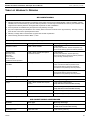
Table 2: R-410A Refrigerant Start-Up Charge
Usethistabletodeterminestartupchargeofsystem.
DuraSea R410A systems use Thermal Expansion Valves to optimize system operation and thus cannot be charged using superheat method
A properly operating TXV will maintain Superheat in range of 10 to 25 degrees.
System must be charged by Subcooling method.
Charge in cool mode steady state to acheive 4 to 8 degrees F of subcooling at condenser base valve.
System overcharged with refrigerant can lead to catastrophic failure. Symptoms are high head pressure, high running current, and
high subcooing.
Compressor
Tube Diameter
Unit
24k
30k
36k
48k
60k
72k
90k
120k
Lineset
Liquid Suction Charge/ft
3/8
5/8
0.56
3/8
3/4
0.59
3/8
3/4
0.59
3/8
3/4
0.59
1/2
7/8
1.05
1/2
7/8
1.05
1/2
11/8
1.14
5/8
13/8
1.82
Maximum
Factory
Charge(oz)
Charge (oz)
15
128
128
128
192
192
192
256
272
80
80
80
80
120
120
160
160
-
Charge in ounces to be added by installer for Lineset in feet of length noted
20
3
3
3
3
5
5
6
9
25
6
6
6
6
11
11
11
18
30
8
9
9
9
16
16
17
27
35
11
12
12
12
21
21
23
36
40
14
15
15
15
26
26
29
46
45
17
18
18
18
32
32
34
55
50
20
21
21
21
37
37
40
64
NOTE:Suctionaccumulatorandcrankcaseheatermustbeusedifsystemchargeexceeds"CompressorMaximumCharge".
ConsultDometicApplicationsteam.
Example:
DCA60 with 40 feet (12.1 m) of refrigerant line:
From Table 2 add 26 ounces (737 g) of R-410A refrigerant.
SYSTEM CHECK
1.
The electrical power source must agree with the unit's nameplate rating.
2.
Check all air handler(s) and other equipment auxiliary components. Consult the manufacturer's instructions regarding
any other equipment connected to the condensing unit. If the unit has field-installed accessories, be sure all are
properly installed and correctly wired.
3.
Check tightness of all electrical connections.
4.
Be sure liquid line and low side of the system are properly leak checked and dehydrated.
5.
Be sure the unit is properly evacuated, leak checked, and charged.
6.
Ensure the liquid line and suction line service valves are set to the top seated position.
7.
All barriers and covers must be in place.
NOTE: The units are factory charged with the required amount of oil. If oil recharging is required, call Dometic for proper
amount.
START UNIT
Set the space thermostat to a set point above ambient temperature so that there is no demand for cooling. Close the power
disconnect switch. Reset the space thermostat below ambient temperature so that a call for cooling is ensured.
COMPRESSOR & FAN ROTATION
On 3-phase units with scroll compressors, it is important to be certain that the compressor is rotating in the proper direction.
When a three-phase scroll compressor is operating in reverse it is noisier and its current draw is substantially reduced
compared to rated values. A phase monitor is recommended to indicate reverse power phasing.
The condenser fan should be blowing air toward fan grille.
To correct phase order:
16
1.
Turn off power to the unit, tag disconnect.
2.
Reverse any two of the unit power leads.
3.
Reapply power, verify correct compressor pressures and condenser air flow.
L-3153
DuraSea Condenser Installation, Start-Up & Service Manual
Start Unit
To verify the compressor is rotating in the proper direction:
1.
Connect service gauges to the suction and liquid pressure fittings.
2.
Energize the compressor.
3.
The suction pressure should drop and the liquid pressure should rise, as is normal on any start-up.
COMPRESSOR OVERLOAD
This overload interrupts power to the compressor when either the current or internal motor winding temperature becomes
excessive, and automatically resets when the internal temperature drops to a safe level. This overload may require 60 minutes
(or longer) to reset. If the internal overload is suspected of being open, disconnect the electrical power to the unit and check the
circuit through the overload with an ohmmeter or continuity tester.
CAUTION
Unit Damage Hazard: Failure to follow this caution may result in equipment damage.
Never charge liquid into the low-pressure side of system. Do not overcharge. During charging or removal of
refrigerant, be sure indoor fan system is operating. Ensure outdoor fan motors are running.
FINAL CHARGE ADJUSTMENT
DuraSea R-410A systems use TXVs(Thermal Expansion Valves) to optimize system operation and thus cannot be charged
using the superheat method. System must be charged by Subcooling method.
1.
Operate the unit for a minimum of 15 minutes. Ensure that pressure and temperature readings have stabilized.
2.
Indoor airflow must be within the unit's normal operating range.
3.
Indoor ambient temperature must be in 70°F to 80°F (21°C to 27°C) range.
4.
Mount the temperature sensing device on the liquid (small) line close to the liquid line service valve, and insulate it so
that outdoor ambient temperature does not affect the reading.
5.
Use a thermometer to measure the outdoor ambient temperature. The outdoor temperature will determine the next
step.
Outdoor Temp 65°F (18°C) or Higher
1.
5.
Check subcooling and superheat. Subcooling = Saturated Liquid Temp - Liquid Line Temp. Subcooling should be 6 ±
2°F (3.3 ± 1°C). Superheat = Suction Line Temp - Saturated Suction Temp. Superheat should be 12 ± 4°F (6.6 ± 2°C).
a.
If subcooling and superheat are low, adjust TXV to 10°F to 12°F (5.5°C to 6.6°C) of superheat, then check
subcooling.
b.
If subcooling is low and superheat is high, add charge to raise subcooling to 6 ± 2°F (3.3 ± 1°C) then check
superheat.
c.
If subcooling and superheat are high, adjust TXV valve to 10°F to 12°F (5.5°C to 6.6°C) of superheat, then
check subcooling.
d.
If subcooling is high and superheat is low, adjust TVX valve to 10°F to 12°F (5.5°C to 6.6°C) of superheat and
remove charge to lower the subcooling to 6 ± 2°F (3.3 ± 1°C)
Disconnect manifold set, installation is complete.
NOTE: Do not adjust charge based on suction pressure unless there is a gross undercharge.
L-3153
17
DuraSea Condenser Installation, Start-Up & Service Manual
Start Unit
Figure 7: Blocking Outdoor Coil
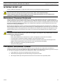
Outdoor Temp Less Than 65°F (18°C)
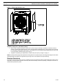
1.
When outdoor ambient temperature is below 65°F (18°C) it may be necessary to restrict the condenser air flow to
achieve normal operating pressures in the 325 to 375 psig (2240 to 2585 kPa) range. These pressures are necessary
for checking the charge. Block equal sections of the outdoor coil on all coil sides until the liquid pressure is in the 325
to 375 psig (2240 to 2585 kPa) range (see Figure 7).
2.
Charge the unit following the steps listed for “Outdoor Temp 65°F (18°C) or Higher” on page 17.
NOTE: Accurate pressure gauge and temperature sensing devices are required. System overcharge with refrigerant can lead to
catastrophic failure. Symptoms are high head, high running current, low superheat, and high subcooling.
SYSTEM OPERATION
The outdoor unit and indoor blower cycle are on demand from the room thermostat. When the thermostat blower switch is in the
ON position, the indoor blower operates continuously. Ensure that all safety controls are operating, control panel covers are on,
and the service panels are in place.
18
L-3153
DuraSea Condenser Installation, Start-Up & Service Manual
Quarterly Inspection (and 30 days after initial start)
MAINTENANCE
These items should be part of a routine maintenance program, to be checked every month or two, until a specific schedule for
each can be identified for this installation:
QUARTERLY INSPECTION
(AND 30 DAYS AFTER INITIAL
START)
•
Return air filter replaced or cleaned as appropriate.
•
Check condensate drain for blockage. Clean if necessary.
SEASONAL MAINTENANCE
These items should be checked at the beginning of each season (or more often if local conditions and usage patterns dictate):
•
Clean and inspect the condenser coil. Can be flushed with low-pressure water hose if necessary.
•
Visually inspect connecting lines and coils for evidence of oil leaks.
•
Check tightness of condenser fan-motor mounting bolts.
•
Check tightness of compressor mounting bolts.
•
Check wiring for loose connections.
•
Check indoor coil. Clean if necessary.
•
Check evaporator blower motor amp draw, compressor amperage, and condenser fan amps.
•
Clean and wipe down cabinet with stainless-steel protectant.
NOTE: If the owner complains of insufficient cooling, gauge the unit and check the refrigerant charge. Refer to “Refrigerant
Charging Guidelines” on page 15.
ROUTINE CLEANING
OF
CONDENSER COILS
Periodic cleaning with an environmentally sound coil cleaner is essential to extend the life of the coils. Coil cleaning should be
part of the unit's regularly scheduled maintenance procedures to ensure long life of the coil. Failure to clean the coils may result
in reduced durability in the environment.
Avoid the use of:
•
Coil brighteners
•
High-pressure washers
•
Poor-quality water for cleaning
•
Use of non-recommended coil cleaners is strongly discouraged since coil and unit durability could be affected.
CAUTION
Unit Damage Hazard: Failure to follow this caution may result in corrosion and damage to the unit.
Harsh chemicals, household bleach, or acid or basic cleaners should not be used to clean outdoor or indoor coils of
any kind. These cleaners can be very difficult to rinse out of the coil and can accelerate corrosion at the fin/tube
interface where dissimilar materials are in contact. If there is dirt below the surface of the coil use an environmentally
sound coil cleaner as described above.
CAUTION
Unit Reliability Hazard: Failure to follow this caution may result in reduced unit performance.
High-velocity water from a pressure washer, garden hose, or compressed air should never be used to clean a coil. The
force of the water or air jet will bend the fin edges and increase airside pressure drop.
ROUTINE CLEANING & PROTECTION
OF
CABINET
Check the exterior cabinet of the unit periodically for any formation of rust on the stainless steel. If found, remove the rust using
WD-40® and a Scotch-Brite® pad.
When clean, apply a stainless-steel protective coating that will prevent surface rust. Reapply it regularly.
WD-40 is a trademark of the WD-40 Company. Scotch-Brite is a trademark of 3M.
L-3153
19
DuraSea Condenser Installation, Start-Up & Service Manual
Refrigeration System
SERVICE
CAUTION
Equipment Damage Hazard: Failure to follow this caution may result in damage to equipment.
The compressor in a R-410A system uses a POE oil and PVE. These oils are extremely hygroscopic, meaning they
absorb water readily. POE oils can absorb 15 times as much water as other oils designed for HCFC and CFC
refrigerants. Take all necessary precautions to avoid exposure of the oil to the atmosphere.
REFRIGERATION SYSTEM
SERVICING UNITS
ON
ROOFS/DECKS WITH SYNTHETIC MATERIALS
POE (polyolester) compressor lubricants are known to cause long-term damage to some some synthetic materials, including
roofing. Exposure, even if immediately cleaned up, may cause embrittlement (leading to cracking) and possible failure. When
performing any service which may risk exposure of compressor oil to the synthetic surfaces, take appropriate precautions to
protect. Procedures which risk oil leakage include but are not limited to compressor replacement, repairing refrigerant leaks,
replacing refrigerant components such as filter drier, pressure switch, metering device, coil, accumulator, or reversing valve.
LIQUID LINE FILTER DRIER
The factory-provided filter drier is specifically designed to operate with R-410A. Replace the filter drier with factory-authorized
components only with a filter drier with desiccant made from 100% molecular sieve grade XH-11. Filter drier must be replaced
whenever the refrigerant system is opened.
When removing a filter drier, use a tubing cutter to cut the drier from the system. Do not unsweat a filter drier from the
system. Heat from unsweating will release moisture and contaminants from drier into system.
FIELD REFRIGERANT ACCESS PORTS
Field service access to refrigerant pressures is through the access ports located at the service valves. These ports are 1/4-inch
(6.4 mm) SAE Flare couplings with Schrader check valves and service caps. Use these ports to admit nitrogen to the field tubing
during brazing, to evacuate the tubing and evaporator coil, to admit initial refrigerant charge into the low-side of the system and
when checking and adjusting the system refrigerant charge. When service activities are completed, ensure the service caps are
in place and secure; check for leaks. If the Schrader check valve must be removed and re-installed, tighten to 3 in-lbs (34 Ncm).
COMPRESSOR PROTECTION
COMPRESSOR OVER-TEMPERATURE PROTECTION (IP)
A thermostat installed on the compressor motor winding reacts to excessively high winding temperatures and shuts off the
compressor.
LOW-PRESSURE SWITCH
The low-pressure switch is 1/4-inch (6.4 mm) SAE Flare-mounted on the suction line. Switch is fixed, non-adjustable, automatic
reset type. The switch protects compressor from loss of charge situation.
HIGH-PRESSURE SWITCH
The high-pressure switch is 1/4-inch (6.4 mm) SAE Flare mounted on the discharge line. The switch is a fixed, non-adjustable
automatic reset type. The switch shuts off the compressor when discharge pressure rises above the factory setting.
LOW-AMBIENT OPTION
Units with the factory installed low-ambient option will disengage the condenser fan when head pressure drops below a
specified value and re-engage fan when head pressure climbs above reset value.
LUBRICATION
FAN MOTORS
The fan motors have sealed bearings. No provisions are required for lubrication.
COMPRESSOR
The compressor has its own oil supply. Loss of oil due to a leak in the system should be the only reason for adding oil after the
system has been in operation.
20
L-3153
DuraSea Condenser Installation, Start-Up & Service Manual
Troubleshooting
GENERAL TROUBLESHOOTING
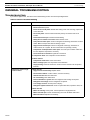
TROUBLESHOOTING
If you have a digital control, refer also to the troubleshooting section of the manual packaged with it.
Table 3: General Troubleshooting
PROBLEM
Compressor does not run.
POSSIBLE REASON/SOLUTION
Contactor Open:
1. Power off. Restore power.
2. Fuses blown in field power circuit. After finding cause and correcting, replace with
correct size fuse.
3. No control power. Check control transformer primary connections and circuit
breaker.
4. Thermostat circuit open. Check thermostat setting.
5. Safety device lockout circuit active. Reset lockout circuit.
6. Low-pressure switch open. Check for refrigerant undercharge, obstruction of indoor
airflow. Make sure liquid line solenoid valve(s) is open.
7. High-pressure switch open. Check for refrigerant overcharge, obstruction of
outdoor airflow, air in system. Be sure outdoor fans are operating correctly.
8. Compressor overtemperature switch open. Check for open condition. Allow time
for reset. Replace compressor if necessary.
9. Loose electrical connections. Tighten all connections.
10. Compressor stuck. See compressor service literature.
Contactor Closed:
1. Compressor leads loose. Check connections.
2. Motor windings open. See compressor service literature.
3. Single phasing. Check for blown fuse. Check for loose connection at compressor
terminal.
Compressor stops on highpressure switch.
Outdoor Fan On:
1. High-pressure switch faulty. Replace switch.
2. Reversed fan rotation. Confirm rotation, correct if necessary.
3. Airflow restricted. Remove obstruction.
4. Air recirculating. Clear airflow area.
5. Noncondensables in system. Recover refrigerant and recharge as required.
6. Refrigerant overcharge. Recover refrigerant as required.
7. Line voltage incorrect. Consult power company.
8. Refrigerant system restrictions. Check or replace filter drier, expansion valve, etc.
Outdoor Fan Off:
1. Motor not running. Check power. Check capacitor for single-phase fan.
2. Motor overload open. Check overload rating. Check for fan blade obstruction.
3. Motor burned out. Replace fan assembly.
L-3153
21
DuraSea Condenser Installation, Start-Up & Service Manual
Troubleshooting
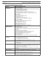
Table 3: General Troubleshooting (continued)
PROBLEM
POSSIBLE REASON/SOLUTION
Compressor cycles on lowpressure switch.
Indoor-Air Fan Running
1. Liquid line solenoid valve(s) fails to open. Check liquid line solenoid valve(s) for
proper operation. Replace if necessary.
2. Filter drier plugged. Replace filter drier.
3. Expansion valve power head defective. Replace power head.
4. Low refrigerant charge. Add charge. Check low-pressure switch setting.
Airflow Restricted
1. Coil is iced. Check refrigerant charge.
2. Coil dirty. Clean coil fins.
3. Air filters dirty. Clean or replace filters.
4. Dampers closed. Check damper operation and position.
Indoor-Air Fan Stopped
1. Electrical connections loose. Tighten all connections.
2. Fan relay defective. Replace relay.
3. Motor overload open. Power supply.
4. Motor defective. Replace motor.
5. Fan belt broken or slipping. Replace or tighten belt.
Compressor running but
cooling insufficient.
Suction Pressure Low
1. Refrigerant charge low. Add refrigerant.
2. Head pressure low. Check refrigerant charge. Check outdoor fan cycling control
operation.
3. Air filters dirty. Clean or replace filters.
4. Expansion valve power head defective. Replace power head.
5. Indoor coil partially iced. Check low-pressure setting.
6. Indoor airflow restricted. Remove obstruction.
Suction Pressure High
1. Heat load excessive. Check for open doors or windows in vicinity of fan coil.
Unit operates too long or
continuously.
1. Low refrigerant charge. Add refrigerant.
2. Control contacts fused. Replace control.
3. Air in system. Purge and evacuate system.
4. Partially plugged expansion valve or filter drier. Clean or replace.
System is noisy.
1. Piping vibration. Support piping as required.
2. Compressor noisy. Check mounts. Check tubing for rubbing. Replace compressor if
bearings are worn.
Compressor loses oil.
1.
Leak in system. Repair leak.
2. Crankcase heaters not energized during shutdown. Check wiring and relays.
Check heater and replace if defective.
3. Improper interconnecting piping design. Check piping for oil return. Replace if
necessary.
Frosted suction line.
1. Expansion valve admitting excess refrigerant. Adjust expansion valve.
Hot liquid line.
1. Shortage of refrigerant due to leak. Repair leak and recharge.
2. Expansion valve opens too wide. Adjust expansion valve.
Frosted liquid line.
1. Restricted filter drier. Remove restriction or replace.
2. Liquid line solenoid valve partially closed. Replace valve.
22
L-3153
DuraSea Condenser Installation, Start-Up & Service Manual
Preliminary Information
START-UP CHECKLIST
PRELIMINARY INFORMATION
OUTDOOR: MODEL NO. ___________________________ SERIAL NO. ________________________
INDOOR: AIRHANDLER MANUFACTURER _____________________________________
MODEL NO. ___________________________ SERIAL NO. ________________________
PRE-START-UP
OUTDOOR UNIT
IS THERE ANY SHIPPING DAMAGE? (Y/N) __________
IF SO, WHERE: __________________________________________________________________________
WILL THIS DAMAGE PREVENT UNIT START-UP? (Y/N) ___________
CHECK POWER SUPPLY. DOES IT AGREE WITH UNIT? (Y/N) ___________
HAS THE GROUND WIRE BEEN CONNECTED? (Y/N) ___________
HAS THE CIRCUIT PROTECTION BEEN SIZED AND INSTALLED PROPERLY? (Y/N) ___________
ARE THE POWER WIRES TO THE UNIT SIZED AND INSTALLED PROPERLY? (Y/N) ___________
CONTROLS
ARE THERMOSTAT AND INDOOR FAN CONTROL WIRING CONNECTIONS MADE AND CHECKED? (Y/N) ___________
ARE ALL WIRING TERMINALS (including main power supply) TIGHT? (Y/N) ___________
IF APPLICABLE, HAS CRANKCASE HEATER BEEN ENERGIZED FOR 24 HOURS? (Y/N) ___________
INDOOR UNIT
HAS WATER BEEN PLACED IN DRAIN PAN TO CONFIRM PROPER DRAINAGE? (Y/N) ___________
ARE PROPER AIR FILTERS IN PLACE? (Y/N) ___________
HAS CORRECT FAN ROTATION BEEN CONFIRMED? (Y/N) ___________
PIPING
ARE LIQUID LINE SOLENOID VALVES LOCATED AT THE INDOOR COILS AS REQUIRED? (Y/N) ___________
HAVE LEAK CHECKS BEEN MADE AT COMPRESSOR, OUTDOOR AND INDOOR COILS, TXVs (Thermostatic Expansion
Valves), SOLENOID VALVES, FILTER DRIERS, AND FUSIBLE PLUGS WITH A LEAK DETECTOR? (Y/N) ___________
LOCATE, REPAIR, AND REPORT ANY LEAKS. ________________________
HAVE LIQUID LINE SERVICE VALVES BEEN OPENED? (Y/N) ___________
HAVE SUCTION LINE SERVICE VALVES BEEN OPENED? (Y/N) ___________
CHECK VOLTAGE IMBALANCE
LINE-TO-LINE VOLTS: AB __________V AC ___________V BC ______________V
(AB + AC + BC)/3 = AVERAGE VOLTAGE = _____________V
MAXIMUM DEVIATION FROM AVERAGE VOLTAGE = _______________V
VOLTAGE IMBALANCE = 100 X (MAX DEVIATION)/(AVERAGE VOLTAGE) = ___________________
IF OVER 2% VOLTAGE IMBALANCE, DO NOT ATTEMPT TO START SYSTEM!
CALL LOCAL POWER COMPANY FOR ASSISTANCE.
CHECK INDOOR UNIT FAN SPEED AND RECORD. _____________________________________
CHECK OUTDOOR UNIT FAN SPEED AND RECORD. ___________________________________
AFTER AT LEAST 15 MINUTES RUNNING TIME, RECORD THE FOLLOWING MEASUREMENTS:
SUCTION PRESSURE ______________________
L-3153
23
Pre-Start-Up
DuraSea Condenser Installation, Start-Up & Service Manual
SUCTION LINE TEMP ______________________
SUBCOOLING TEMP ______________________
LIQUID PRESSURE _______________________
LIQUID LINE TEMP _______________________
SUPERHEAT TEMP ______________________
ENTERING OUTDOOR UNIT AIR TEMP ______________________
LEAVING OUTDOOR UNIT AIR TEMP _______________________
INDOOR UNIT ENTERING-AIR DB (dry bulb) TEMP __________________
INDOOR UNIT ENTERING-AIR WB (wet bulb) TEMP _________________
INDOOR UNIT LEAVING-AIR DB TEMP _____________________
INDOOR UNIT LEAVING-AIR WB TEMP _____________________
COMPRESSOR 1 AMPS (L1/L2/L3) _______________/_____________/________________
NOTES:
24
L-3153
DuraSea Condenser Installation, Start-Up & Service Manual
Section I - What’s Covered
OWNERS LIMITED WARRANTY
As hereinafter described, Dometic limits the duration of any implied warranty to the duration of the underlying express
warranty and also disclaims any liability for consequential or incidental damages arising from any application,
installation, use or malfunction of any warranted product.
SECTION I - WHAT’S COVERED
What does the Limited Warranty cover?
Products manufactured by Dometic Corporation (Dometic) are under limited warranty to be free from defects in workmanship or
materials. This being under normal use and service, with the obligation of Dometic under this limited warranty, being limited to
replacing or repairing any component(s) which shall disclose defects within the limits defined in Section III. Which upon
examination by Dometic, shall appear to the satisfaction of Dometic to be defective or not up to specifications.
This Limited Warranty is made in lieu of all other express warranties, obligations, or liabilities on the part of Dometic.
In addition, Dometic shall not be responsible for any incidental or consequential damages. In those instances in which a
cash refund is made, such refund shall effect the cancellation of the contract of sale without reservation of rights on the part of
the purchaser. Such refund shall constitute full and final satisfaction of all claims which the purchaser has or may have
against Dometic due to any actual or alleged breach of warranty, either express or implied, including, without
limitation, any implied warranty or merchantability or fitness for a particular purpose. Some states do not allow the
exclusion or limitation of incidental or consequential damages so the above limitation may not apply to you.
The Dealer is not an agent for Dometic, except for the purpose of administering the above warranty to the extent herein
provided. Dometic does not authorize the dealer or any other person to assume for Dometic any liability in connection
with such warranty, or any liability or expense incurred in the replacement or repair of its products other than those
expressly authorized herein. Dometic shall not be responsible for any liability or expense except as is specifically
authorized and provided in this section.
Dometic reserves the right to improve its products, through changes in design or material without being obligated to incorporate
such changes in products of prior manufacture. Dometic can make changes at any time in design, materials, or part of units of
any one, model year, without obligation or liability to owners of units of the same year's model of prior manufacture.
This warranty gives you; the purchaser, specific legal rights, and you may also have other rights which vary from state to state.
You also have implied warranty rights, including an implied warranty of merchantability, which means that your product must be
fit for the ordinary purposes for which such goods are used. The duration of any implied warranty rights is limited to the
duration of the express warranty as found in Section III. Some states do not allow limitations on how long an implied
warranty lasts, so the above limitation may not apply to you.
SECTION II - WHAT’S NOT COVERED
What does this Limited Warranty not cover?
This Warranty Shall Not Apply to:
1.
Failures resulting from improper installation or use contrary to instructions.
2.
Failures resulting from abuse, misuse, accident, fire, or submergence.
3.
Any part manufactured by Dometic, which shall have been altered so as to impair its original characteristics.
4.
Any parts which fail as a result of misuse, improper application or improper installation.
5.
Items not manufactured by Dometic, i.e., items, which are purchased from another manufacturer and supplied as
received by Dometic without alteration or modification except as any part of a Dometic manufactured unit or
component.
6.
Components or parts used by or applied by the purchaser, as an integral part of products not manufactured by
Dometic.
7.
Labor resulting from difficult access to a Dometic product. The original installer or OEM is responsible for accessibility
of unit.
8.
Leaks due to improper installation of split systems and refrigeration systems, for example; packing glands, flare nuts,
quick disconnects. The adjustment of the refrigerant charge on a split system should be charged to the original
installer or OEM.
9.
Freight Damage (see page 10 for instructions for handling freight damage).
10. Pumps that have been run dry, are water damaged or have blown freeze plugs.
11. Pumps with cracked heads.
12. Pump seals are not covered.
L-3153
25
Section III - Coverage Period
DuraSea Condenser Installation, Start-Up & Service Manual
13. UV light bulbs are not covered.
14. Liquid line filter dryers are not covered.
15. Blowers with water damage.
16. Logic boards with water damage.
17. Logic boards with blown MOV's (Power Surge)
18. Mis-programmed displays.
19. Display heads with water damage.
20. Dirty Condensers and/or Evaporators.
21. Failures due to improper winterization.
22. Unit damage as a result of improper return packaging.
23. Replacement of freon with substitute without authorization from factory.
24. Environmental and/or Recovery Fees.
25. Welding and Nitrogen Fees.
26. Travel costs are included in the hourly labor allowances and should not be billed as a separate item without
preapproval form the factory.
Installation and application of Dometic components is not warranted by Dometic, because Dometic has no control or
authority over the selection, location, application, or installation of these components.
SECTION III - COVERAGE PERIOD
What is the period of coverage?
(See Limited Warranty Periods at the end of this book).
All Dometic components bear a data plate on which there are model and serial numbers. The serial number is date coded. To
determine whether or not any Dometic component is in warranty, proceed as follows:
1.
Determine the manufacture date of the component from the serial number on the data plate. If you are not familiar with
the date code, write or call the Dometic Customer Service Department to obtain the manufacture date. The hours of
the Customer Service Department are 8:00 a.m. - 5:00 p.m. (USA, Eastern Standard Time Zone) Monday through
Friday excluding holidays.
2.
It is possible that there might exist a considerable time lag between the date a component is manufactured and the
date it is put in service. In such instances, the date of manufacture could indicate that the item is out of warranty.
However, based on the date the equipment is first put in service, the item may still be covered by the Dometic warranty
as described in Section I. For proof of date put in service, Dometic will require a copy of the bill of sale of the Dometic
equipment from the installer or new boat dealer to the original owner.
SECTION IV - GETTING SERVICE
How do you get service?
Please read the following Warranty Procedure:
If the failure of a Dometic component is determined to be covered under the Dometic warranty and the time in service is
determined to be within the warranty time limit, the owner has the following three options:
1.
Preferred option: Have a Dometic authorized Servicing Dealer, perform the work needed. The customer needs to call
Dometic Customer Service Department for a recommendation as to the closest dealer. If the customer already knows
an authorized servicing dealer, the dealer should be contacted directly.
2.
Second option: If the customer contacts Dometic Service Department for a Servicing Dealer and Dometic has no one
in that particular area, Dometic will authorize the use of a local service company and Dometic will work with the local
company to assist in any way possible.
3.
Third option: The customer may send his equipment back to the factory to have the repair work done. Dometic will
make every effort to return the equipment to the customer within a three week time period. If the claim represents a
legitimate warranty problem, Dometic will pay the freight both ways. Dometic prefers option one first, option two
second, and option three only if one and two are not available.
The customer may contact the Dometic Service Departments at (804) 746-1313 (Virginia plant) or (954) 973-2477 (Florida
plant) Monday through Friday, 8:00am - 5:00pm.
After hours (evenings and weekends) technical support is offered through Dometic's 24/7 Hotline at (888) 440-4494.
26
L-3153
DuraSea Condenser Installation, Start-Up & Service Manual
TABLE
OF
Table of Warranty Periods
WARRANTY PERIODS
AIR CONDITIONING
Important Notes:
1. Warranty periods begin from the date of possession of the boat by the first owner if OEM installed or date of installation if dealer
installed, but not to exceed three (3) years from date of production. The warranty is transferable and will carry the remainder of the
original owner's warranty based on the original date of purchase or date of installation.
2. Proof of purchase or installation may be required to verify warranty coverage.
3. Any unit or replacement part installed due to a warranty failure carries the remainder of the original warranty. Warranty coverage
does not start over from the repair/replacement date.
4. Warranty coverage shall not exceed three (3) years from the date of production.
5. These warranty periods are effective March 1, 2010.
Direct Expansion, Self-Contained and Split-Systems
Product
Sale Type
Warranty Coverage
DuraSea Condeser
OEM or Dealer Installed.
2-Year Warranty
1st Year parts and labor, 2nd Year compressor only.
Not to exceed three (3) years from date of production.
Emerald Series
Stowaway Turbo
Stowaway
Vector Turbo
Vector Compact
Condensers and Evaporators
OEM or Dealer Installed with digital or
mechanical controls.
2-Year Warranty
1st Year parts and labor, 2nd Year parts only.
Not to exceed three (3) years from date of production.
Pump warranty, see Pump section.
Cabin Mate
Cool Mate
Catalog Sales
Parts: 1 year from date of purchase of unit.
Labor: 6 months from date of purchase of unit.
Not to exceed three (3) years from the date of
manufacture. Pump warranty, see Pump section.
OEM or Dealer Installed
1-Year Warranty, parts and labor.
Not to exceed three (3) years from date of
manufacture. Pump warranty, see Pump section.
Pumps, Compressors, Replacement Parts
Product
Sale Type
Warranty Coverage
Pumps
OEM or Dealer Installed with complete
system.
1-Year warranty, parts and labor.
Pump seals are not covered under warranty.
Dealer Installed and Aftermarket sales.
1-Year warranty, parts only.
Pump seals are not covered under warranty.
Compressors
Aftermarket sales
1-Year warranty, parts only
Replacement parts and components
Aftermarket sales
90-Day warranty, parts only
AIR CONDITIONING ACCESSORIES
Product
Sale Type
Warranty Coverage
In-Duct Breathe Easy Air Purifiers
Aftermarket sales
1-Year warranty, parts only
UV bulb is not covered under warranty.
SmartStart Control
Aftermarket sales
1-Year warranty, parts only
L-3153
27
NOTES
NOTES