1
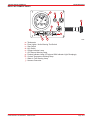
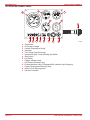
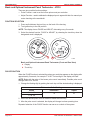
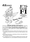
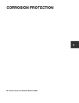
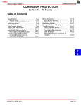
INSTRUMENTATION SERVICE MANUAL NUMBER 29 ELECTRICAL SYSTEM Section 4D - Instrumentation Table of Contents Identification . . . . . . . . . . . . . . . . . . . . . . . . 4D-2 Gauges . . . . . . . . . . . . . . . . . . . . . . . . . 4D-2 Panels . . . . . . . . . . . . . . . . . . . . . . . . . . 4D-2 Tools . . . . . . . . . . . . . . . . . . . . . . . . . . . . . . 4D-5 Lubricants / Sealants / Adhesives . . . . . 4D-5 Wire Color Abbreviations . . . . . . . . . . . . . 4D-5 Precautions . . . . . . . . . . . . . . . . . . . . . . . . 4D-6 General Information . . . . . . . . . . . . . . . . . 4D-7 Tachometer Special Information . . . . . . . 4D-7 Quicksilver Tachometers . . . . . . . . . . . 4D-7 Tachometer Signal Harness Assembly 4D-7 Basic and Optional Instrument Panel Tachometer - VDO) . . . . . . . . . . . . . . . 4D-8 Quicksilver Gauges . . . . . . . . . . . . . . . . . . 4D-10 Lighting Options . . . . . . . . . . . . . . . . . . 4D-10 Testing . . . . . . . . . . . . . . . . . . . . . . . . . . 4D-11 Gauge Replacement . . . . . . . . . . . . . . 4D-14 Quicksilver Primary Station Switches . . 4D-15 Ignition Key Switch . . . . . . . . . . . . . . . 4D-15 Stop Switch . . . . . . . . . . . . . . . . . . . . . . 4D-17 Audio Warning Test and Panel Light Switch . . . . . . . . . . . . . . . . . . . . . . . . . . . . . . . . . . 4D-19 Quicksilver Secondary Station Switches 4D-21 Audio Warning Test and Panel Light Switch . . . . . . . . . . . . . . . . . . . . . . . . . . . . . . . . . . 4D-21 Start Switch . . . . . . . . . . . . . . . . . . . . . . 4D-21 Stop Switch . . . . . . . . . . . . . . . . . . . . . . 4D-23 CMD-4081866 / 90-863016001 MARCH 2008 Basic and Optional Instrument Panel - Primary Station Switches . . . . . . . . . . . . . . . . . . . . 4D-24 Ignition Key Switch . . . . . . . . . . . . . . . 4D-24 Audio Warning Test and Panel Light Switch . . . . . . . . . . . . . . . . . . . . . . . . . . . . . . . . . . 4D-26 Stop Switch . . . . . . . . . . . . . . . . . . . . . . 4D-27 Basic and Optional Instrument Panel Secondary Station Switches . . . . . . . . . . 4D-28 Senders / Sensors . . . . . . . . . . . . . . . . . . . 4D-28 Tachometer Sensor . . . . . . . . . . . . . . . 4D-28 Oil Pressure Sender . . . . . . . . . . . . . . 4D-29 Coolant Temperature Sender . . . . . . . 4D-31 Audio Warning System . . . . . . . . . . . . . . . 4D-34 Alarm . . . . . . . . . . . . . . . . . . . . . . . . . . . 4D-34 Oil Pressure Switch . . . . . . . . . . . . . . . 4D-35 Coolant Temperature (Overheat) Switch . . . . . . . . . . . . . . . . . . . . . . . . . . . . . . . . . . 4D-37 Remote Control / Neutral Start Safety Circuit Quicksilver Instrumentation . . . . . . . . . . . 4D-40 Primary Station . . . . . . . . . . . . . . . . . . . 4D-40 Secondary Station . . . . . . . . . . . . . . . . 4D-41 Adapter Harness Assembly - 9 Pin To 21 Pin . . . . . . . . . . . . . . . . . . . . . . . . . . . . . . . . . . . . . 4D-44 Adapter Harness Assembly - 9 Pin To 21 Pin (Continued) . . . . . . . . . . . . . . . . . . . . . . . . . 4D-45 Descriptions . . . . . . . . . . . . . . . . . . . . . 4D-45 Harness Connectors . . . . . . . . . . . . . . 4D-45 Page 4D-1 4 D INSTRUMENTATION SERVICE MANUAL NUMBER 29 Identification Gauges QUICKSILVER INSTRUMENTS NOTE: One of three distinct series of Quicksilver gauges may be installed. Aside from different gauge face appearances and styling, the back of the gauges and wiring connections are different. 72965 Typical QSI Series (If Equipped) 77333 Typical Admiral Series (Back of Flagship Series Similar) Panels QUICKSILVER INSTRUMENTS 73546 Typical Quicksilver Page 4D-2 CMD-4081866 / 90-863016001 MARCH 2008 INSTRUMENTATION SERVICE MANUAL NUMBER 29 BASIC INSTRUMENT PANEL a c b j d h e i f a b c d e f g h i j g 77389 - Tachometer - Panel Lights / Audio Warning Test Switch - Stop Switch - Key Switch - Charge Indicator Lamp - Oil Pressure Warning Lamp - Preheat Indicator Lamp (If Equipped With Indicator Light Glowplugs) - Coolant Temperature Warning Lamp - Water In Fuel Warning Lamp - Harness Connector CMD-4081866 / 90-863016001 MARCH 2008 Page 4D-3 INSTRUMENTATION SERVICE MANUAL NUMBER 29 OPTIONAL INSTRUMENT PANEL b a c e d n i a b c d e f g h i j k l m n Page 4D-4 j k l m f g h 77764 - Tachometer - Oil Pressure Gauge - Coolant Temperature Gauge - Voltmeter - Trim Gauge (Sterndrive only) - Instrument Lights / Audio Warning Test Switch - Stop Switch - Key Switch - Charge Indicator Lamp - Oil Pressure Warning Lamp - Preheat Indicator Lamp (If Equipped With Indicator Light Glowplug) - Coolant Temperature Warning Lamp - Water In Fuel Warning Lamp - Harness Connector CMD-4081866 / 90-863016001 MARCH 2008 INSTRUMENTATION SERVICE MANUAL NUMBER 29 Tools Description Part Number Digital MultiMeter 91-99750A1 Connector Test Adapter Kit J-35616-A Equipment for performing tests (suitable container, thermometer, suitable heat source, sandblasting sand or equivalent and a 12 volt power source) Obtain Locally Diesel Timing Tool or suitable service tachometer Obtain Locally Lubricants / Sealants / Adhesives Description Where Used Method of Use Part Number Liquid Neoprene Exposed terminals and connections Light coating on surfaces 92-25711--3 Loctite Pipe Sealant with Teflon Senders, sensors and plugs Apply to threads Obtain Locally Wire Color Abbreviations BLK BLU BRN GRY GRN ORN PNK CMD-4081866 / 90-863016001 MARCH 2008 Black Blue Brown Gray Green Orange Pink PUR or PPL RED TAN WHT YEL LIT or LT DRK Purple Red Tan White Yellow Light Dark Page 4D-5 INSTRUMENTATION SERVICE MANUAL NUMBER 29 Precautions WARNING Always disconnect battery cables from battery before working around electrical system components to prevent injury to yourself or damage to electrical system. CAUTION Avoid short circuits. It may be necessary to remove instrument panel from dashboard to gain access to instruments and switches. Do not allow wires to come in contact with metal or other wires. WARNING Switch and sender testing involves the use of intense heat. Failure to follow appropriate procedures or warnings can cause burns which can result in severe personal injury. While performing the following test, observe these general precautions: • Wear personal protective clothing such as rubber gloves, a non-flammable apron and eye protection - preferably full face shield or safety glasses. • The appropriate heat source should only be electric. Heat source should be operated by a qualified person. Be sure to follow all instructions of the manufacturer of the heat source. The heat source should be checked each time it is used to be sure it is functioning properly. • The thermometer used in the test should be a high- temperature thermometer with a maximum reading of at least 150°C (300°F). Under no circumstances should the operator allow temperatures to exceed test specifications. • Perform test only in a well ventilated area. • Use a suitable container, such as metal, to hold the sand. Avoid use of glass containers unless the operator first confirms for himself/herself that the glass container is an appropriate high-temperature vessel. • Because the components will reach high temperatures Do NOT handle materials or components until COMPLETELY cooled. WARNING Use only clean, dry sand such as used for general sandblasting purposes. Use of sand containing contaminants could result in hazards such as fire, short circuiting, hot-spots, or other hazards. Page 4D-6 CMD-4081866 / 90-863016001 MARCH 2008 INSTRUMENTATION SERVICE MANUAL NUMBER 29 General Information IMPORTANT: If all instruments appear suspect, an electrical overload may have occurred. A fuse may be defective or a circuit breaker may be tripped open. The cause must be found and corrected before replacing fuse or resetting circuit breaker. IMPORTANT: If all instruments appear suspect, check the main harness or electrical connector to ensure good contact. Before testing individual instruments, check the following: • All wires in circuit are connected. • Connectors are fully engaged. • Battery is fully charged. • All connections are tight and corrosion free. • Circuit breaker is closed. Tachometer Special Information Quicksilver Tachometers Quicksilver tachometers provided by Cummins MerCruiser Diesel use a tachometer sensor which is part of the engine wiring harness. If using a tachometer from another manufacturer that must be connected to the alternator for driving the tachometer, refer to tachometer manufacturer’s instructions. If using the Quicksilver Tachometer recommended for the engine package, the appropriate setting of the switch located on the back of the tachometer is given in the following chart. Tachometer Switch Setting Model Number Of Cylinders Switch Position 4 11 D1.7L DTI Sterndrive 1.7 MI 120 Inboard 1 Signal is 2 pulse counts per revolution. Tachometer Signal Harness Assembly All engine harness assemblies have a separate smaller harness that connects between the tachometer sensor and the engine harness connector. This tachometer signal harness assembly is attached with loop and hook to the back of the electrical bracket by the factory. There are two separate assemblies: • One for models with Indicator Lamp Glow Plug Systems. • One for Wait To Start Glow Plug Systems. Refer to Sections 4C and 4E for additional information. CMD-4081866 / 90-863016001 MARCH 2008 Page 4D-7 INSTRUMENTATION SERVICE MANUAL NUMBER 29 Basic and Optional Instrument Panel Tachometer - VDO There are two possible function settings: • Pulse Function- used to set the known pulse count per revolution. • Adjust Function - used to calibrate the displayed rpm to agree with that of a manual rpm meter checking at the crankshaft. FUNCTION SELECTION 1. Press and hold down the touch key on the back of the housing. 2. Turn ignition key to the ON position. NOTE: The display shows PULSE and ADJUST, alternating every 2 seconds. 3. Select the desired function, PULSE or ADJUST, by releasing the touch key when the designated word is displayed. a b 77390 Basic and Optional Instrument Panel Tachometer (Front and Rear View) a - Display b - Touch Key PULSE FUNCTION When the PULSE function is selected the pulses per revolution appears on the display after approximately 3 seconds, for example P 14.50. The last digit in the display will flash. NOTE: Begin with the entry of the known pulse count immediately. Possible pulse count settings are 0.50 to 399.99. 1. Change the flashing digit by pushing the touch key until the desired setting is displayed. Tachometer Switch Setting Model D1.7L DTI 1.7 MI 120 Pulses/Rev Adjust 2 0 2. When the desired pulse count is reached release the touch key. 3. After the pulse count is selected, the display will change to show operating time. Repeated selection of the PULSE function can serve as a check of the system. Page 4D-8 CMD-4081866 / 90-863016001 MARCH 2008 SERVICE MANUAL NUMBER 29 INSTRUMENTATION ADJUST FUNCTION NOTE: Two people are required to make the following adjustments. The adjustment can be made only from 30 to 100% of the indicator range. IMPORTANT: When the ADJUST function is selected, the display shows UP or DOWN alternating every 3 seconds. NOTE: The pointer range changes very slowly at first, facilitating high-precision setting. The rate at which the pointer range changes increases the longer the key is held down. 1. Connect a suitable service tachometer to the crankshaft of the engine. 2. Approximately 3 seconds after selecting the ADJUST function the letters UP or DN (meaning UP and DOWN) will begin to flash. 3. Press and hold the key when UP is displayed and the pointer range will increase. 4. Release the key for 2 seconds and then press it again and the pointer range will decrease. 5. When the tachometer reading is equal to the measured crankshaft rpm, release the key. 6. The display will then alternate between rpm and operating time. 7. Gauge adjustment is complete. During normal operation it is possible to do a fine adjustment by using the key. The adjustment range is + / – 20%. 1. Press the touch key during the normal operation. In the display appears A 0.0. 2. Press and hold the key to increase the adjustment factor by 0.5% steps. 3. Release the key for 2 seconds and then press again to decrease the adjustment factor by 0.5% steps. 4. If the key is not pressed for 5 seconds, the adjustment factor will be stored and the indicator will switch to the normal operating hours display. CMD-4081866 / 90-863016001 MARCH 2008 Page 4D-9