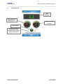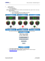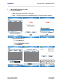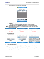
1
LDARtools phx21™ User Manual Version 6 August 20, 2013 phx21_User_Manual_082013 Confidential and Proprietary Looking Forward © 2013 LDARtools LDARtools Table of Contents Page TOC-1 Table of Contents Section 1 phx21™ Connections End Plate ............................................................................................ 1-1 Section 2 phx21™ Maintenance Procedures ......................................................................................... 2-1 A. H2 Fill Procedure ............................................................................................................................ 2-1 B. Power On/Off Procedure ................................................................................................................ 2-2 C. Charging Procedure ....................................................................................................................... 2-3 D. Changing Inlet Filter ....................................................................................................................... 2-4 E. Replacing Probe Tip Filter / Connecting Probe.............................................................................. 2-5 F. Removing Flame Arrestor .............................................................................................................. 2-6 Section 3 Level 1 phx21™ Repair .......................................................................................................... 3-1 A. phx21™ Tool Kit ............................................................................................................................. 3-1 B. Opening phx21™ Case .................................................................................................................. 3-2 C. Battery Replacement ...................................................................................................................... 3-3 D. Probe Flow Pressure Adjustment................................................................................................... 3-4 E. LPH2 Pressure Adjustment ............................................................................................................ 3-5 F. Pump Replacement ........................................................................................................................ 3-6 G. Bluetooth® Replacement ............................................................................................................... 3-8 H. Charger Bulkhead Installation ........................................................................................................ 3-9 I. Glowplug Replacement ................................................................................................................ 3-10 Section 4 Daily Connection / Calibration ................................................................................................ 4-1 A. Connect PDA to phx21™ ............................................................................................................... 4-1 B. The Display Tab ............................................................................................................................. 4-2 C. Igniting phx21™ ............................................................................................................................. 4-3 D. Manual Daily Calibration for phx21™ ............................................................................................ 4-4 E. Daily Calibration Reports ............................................................................................................... 4-5 Section 5 Monitoring with phx21™ ......................................................................................................... 5-1 A. Monitoring with phx21™ ................................................................................................................. 5-1 B. Error Messages .............................................................................................................................. 5-2 Section 6 phx21™ Menu Options / Additional Information .................................................................... 6-1 A. phx21™ Menu Options .................................................................................................................. 6-1 B. Response Tab ................................................................................................................................ 6-3 Section 7 Frequently Asked Questions ................................................................................................. 7-1 Section 8 phx21™ Maintenance Check ................................................................................................. 8-1 phx21_User_Manual_082013 Confidential and Proprietary Looking Forward © 2013 LDARtools LDARtools Section 1 Connections End Plate Page 1-1 phx21™ Connections End Plate phx21™ Connection End Plate: 1. Hydrogen (H2) Fill 2. Inlet filter / Probe port 3. Plug/Charger 4. Power Button 5. Antenna 1 phx21_User_Manual_082013 Confidential and Proprietary 2 3 4 5 Looking Forward © 2013 LDARtools LDARtools Section 2 A. phx21™ Maintenance Procedures Page 2-1 phx21™ Maintenance Procedures H2 Fill Procedure To Fill H2 Bottle: 1. Remove cap over H2 Fill port (Figure 1). 2. Make sure H2 Cylinder has regulator in place and pressure is set at or below 1800 psi. NOTE: Purge H2 Fill adapter for ½ second by turning handle 180° clockwise, if pressure is below 500 lbs on top gauge. 3. Connect fill adapter to H2 Fill port (Figure 2). 4. Turn handle 180° counter clockwise (Figure 3). 5. Wait 4 – 5 seconds. 6. Turn handle 180° clockwise (should hear a slight hiss from pressure release). 7. To release fill adapter pull up on collar of fill adapter. 8. Replace dust cap on H2 Fill port. Cap in place Cap removed Figure 1 Figure 2: Fill Adapter should be in this position when first connected and when ready to release. phx21_User_Manual_082013 Confidential and Proprietary Figure 3 Looking Forward © 2013 LDARtools LDARtools B. phx21™ Maintenance Procedures Page 2-2 Power On/Off Procedure Power Button: 1. No Light means that power is off. 2. Push and hold button for two seconds to turn power on. 3. Solid Green Light means power is on and phx21™ is connected via Bluetooth. 4. Blinking Green Light means power is on and not connected via Bluetooth. 5. To turn power off, hold power button down for 5-8 seconds. Power Off phx21_User_Manual_082013 Confidential and Proprietary Power On Looking Forward © 2013 LDARtools LDARtools C. phx21™ Maintenance Procedures Page 2-3 Charging Procedure Connecting charger to phx21™: 1. You will need a phx21™ charger (see Figure 1). 2. Turn off phx21™. 3. Remove blue protective cap over charging port by turning cap counter clockwise (Figure 2). 4. Align groove in charger with grove in charging port (Figure 3). 5. Plug charger into phx21™ (Figure 4). 6. Tighten by turning collar on charger cable clockwise (Light on charger will flash when connection is successful). 7. The light should blink until battery is charged, once charged the light will remain solid. Figure 1 Figure 2 Figure 3 Figure 4 Note: Blue protective cap MUST be in place when phx21™ is in use in a hazardous area. To power phx21™ with a charger: 1. Connect Charger. The Battery will not charge while the pump is on. 2. phx21™will run as long as h2 is available. 3. If phx21™ is turned off (pump or power) the charge will see an increase in voltage and think the battery is charged. 4. To charge battery, power down phx21™, then unplug the charger for 5 seconds and then plug it back in. phx21_User_Manual_082013 Confidential and Proprietary Looking Forward © 2013 LDARtools LDARtools D. phx21™ Maintenance Procedures Page 2-4 Changing Inlet Filter Replacing Inlet Filter: 1. This is what the Inlet Filter / Probe Port looks like intact (Figure 1). 2. To remove Inlet Filter Assembly (Figure 2) turn counter-clockwise. NOTE: Replacement O-rings available on www.storeldar.com. 3. Remove Inlet Filter from Inlet Filter Assembly make sure that the o-rings (CF stem o-ring & Probe o-ring) on either side are in good condition (no cracks or tears) (Figure 4). 4. Replace Inlet Filter. 5. Screw Inlet Filter Assembly clockwise into phx21™. Figure 1 Clean Inlet Filter Figure 2 Probe o-ring CF stem o-ring Figure 4 phx21_User_Manual_082013 Confidential and Proprietary Looking Forward © 2013 LDARtools LDARtools E. phx21™ Maintenance Procedures Page 2-5 Replacing Probe Tip Filter / Connecting Probe Replacing the Probe Tip Filter: 1. The Probe Tip Filter is located between the Teflon Tubing and the Probe (Figure 1). NOTE: The Probe Tip Filter must always be clean. If you notice any dirt, metal or water trapped in the Probe Tip Filter replace it immediately. 2. To insert a new Probe Tip Filter first attach the Teflon Tubing (Figure 2). 3. Next attach the Probe (Figure 3). NOTE: the Probe Tip Filter must be in place at ALL times when the phx21™ is running. Figure 2 Figure 1 Figure 3 Connecting the probe to phx21™: NOTE: Probe must be connected before igniting the phx21™ 1. To connect the probe to the phx21™ snap the Probe’s Quick Connect Cable into the Inlet Filter / Probe Port (Figure 1). 2. To disconnect the probe from the phx21™ press the tab in toward the cable and pull out gently. Inlet Filter / Probe Port phx21_User_Manual_082013 Confidential and Proprietary Figure 1 Looking Forward © 2013 LDARtools LDARtools F. phx21™ Maintenance Procedures Page 2-6 Removing Flame Arrestor Removing the Flame Arrestor: 1. To remove the FID Assembly (Figure 1) insert the Flame Arrestor tool into the large groove across the center of the Assembly and turn counter-clockwise. 2. When the FID Assembly has been removed you should see a white Teflon Gasket in place inside the FID port (Figure 2). 3. Re-insert the FID Assembly into the FID Port and hand-tighten clockwise. Teflon Gasket Figure 1 phx21_User_Manual_082013 Confidential and Proprietary Figure 2 Looking Forward © 2013 LDARtools 1. LDARtools Section 3 Level 1 phx21™ Repair Page 3-1 Level 1 phx21™ Repair LDARtools Specialists are available to provide Level 1 phx21™ Repair training. To schedule a training session contact an LDARtools Support Specialist at 1-877-788-1110 ext. 1 or [email protected]. IMPORTANT: Before any repairs are to be performed on site, you must Report an Issue using the LDARtools website, including sending log files, as well as going over diagnosis with LDARtools support personnel. Please note that to protect the intrinsic safety of the phx21™ analyzer ONLY certified personnel may perform the repairs outlined below. Any repairs that cannot be performed based on the procedures in this manual must be authorized, in writing, by LDARtools management. A. phx21™ Tool Kit 1. 2. 3. 4. 5. 6. Tork Hex bit / Stubby Screwdriver 1/6 inch Flat Head Screwdriver Locknut / Fitting Wrench 3/16 inch and ¼ inch Fitting Wrench 5/16 inch and ¼ inch 5/8 inch Socket Wrench Flame Arrestor Tool 1 2 phx21_User_Manual_082013 Confidential and Proprietary 3 4 5 6 Looking Forward © 2013 LDARtools 1. B. LDARtools Level 1 phx21™ Repair Page 3-2 Opening phx21™ Case 1. Unscrew the eight screws on the FID side of the phx21™ using the Tork Hex bit / Stubby Screwdriver. 2. 3. 4. 5. Once all eight screws are removed, lift off the orange end plate. Remove Battery (See Battery Replacement Section for details). Lay phx21™ on its side. Grasp connections end plate with one hand and firmly pull on black case with the other hand. 6. To re-assemble the case slide black casing back on. NOTE: Watch for battery cable and use ruler to move tubing or wires aside if they are interfering. NOTE: Make sure all four metal rods are on the outside. 7. Once black case is in place, replace the FID end plate. 8. Replace screws. o The four outer screws are Tork screws with a rounded head (left picture). o The four screws around the FID Assembly are flat head screws (right picture). phx21_User_Manual_082013 Confidential and Proprietary Looking Forward © 2013 LDARtools 1. C. LDARtools Level 1 phx21™ Repair Page 3-3 Battery Replacement 1. Begin by removing the FID end plate. 2. Remove Foam. 3. Grasp the red cord and carefully disconnect the battery pack. 4. Slide battery pack out of the case. 5. 6. 7. 8. 9. Replace battery. Slide new battery into the case. Reconnect battery cable. Replace Foam. Replace FID end plate. phx21_User_Manual_082013 Confidential and Proprietary Looking Forward © 2013 LDARtools 1. D. LDARtools Level 1 phx21™ Repair Page 3-4 Probe Flow Pressure Adjustment 1. 2. 3. 4. 5. On PDA launch phx21™ software. Tap Menu. Tap Pump On/Bypass. Using the 3/16 inch wrench rotate the locknut counter clockwise to loosen (Picture A). Use the flat head screwdriver to turn stem and adjust probe flow (Picture B). o Target is 1.25Lpm +/- .25Lpm. o Turn clockwise to decrease flow. o Turn counter-clockwise to increase flow. NOTE: When making adjustment to the flow, turn stem very slowly to achieve 1.25Lpm +/-.1Lpm. 6. Check flow meter to assure flow has reached an acceptable range. NOTE: Pump power level when adjusted to 1.25Lpm should be lower than 85%, if not contact support at 1-877-788-1110 ext. 1 or [email protected]. 7. Tighten locknut with screwdriver still in place. 8. Check flow. Flow Meter B A Locknut Stem phx21_User_Manual_082013 Confidential and Proprietary Looking Forward © 2013 LDARtools 1. E. LDARtools Level 1 phx21™ Repair Page 3-5 LPH2 Pressure Adjustment 1. 2. 3. 4. 5. 6. On PDA launch phx21™ software. Select phx21™, connect and run. Tap Menu. Tap Details. Tap Solenoid 1 On (Make sure there is a checkmark). Locate the LPH2 Pressure reading on the PDA screen. LPH2 Pressure should be set at 5.5 psi. 7. Using the 3/16 inch wrench rotate the locknut counter clockwise to loosen (Picture A). 8. Use the flat head screwdriver to turn stem and adjust pressure (Picture B). o Target is 5.5 psi +/- .1 psi. o Turn clockwise to increase pressure. o Turn counter-clockwise to decrease pressure. 9. Toggle Solenoid 1, 5 times. 10. Toggle Solenoid 2, 5 times. 11. Turn on Solenoid 1. 12. Check, readjust if needed repeat step 8. 13. Watch PDA screen to see when pressure reaches the acceptable range. 14. Tighten locknut. Stem A B Locknut phx21_User_Manual_082013 Confidential and Proprietary Looking Forward © 2013 LDARtools 1. F. LDARtools Level 1 phx21™ Repair Page 3-6 Pump Replacement To Remove the Pump: 1. Cut the three zip ties holding the pump in place (see illustration below). 1 3 2 2. Once all the Zip ties are removed begin disconnecting the pump. 3. Use the flat head screwdriver to work the gold reducer/adapter loose from the small teflon tubing (picture A). 4. Gently pinch the large teflon tubing attached to the pump and pull back (picture B). 5. Lift the pump with one hand and disconnect the white connector (picture C). NOTE: DO NOT pull on the wire, grasp the hard plastic connection. A phx21_User_Manual_082013 Confidential and Proprietary B C Looking Forward © 2013 LDARtools 1. LDARtools Level 1 phx21™ Repair Page 3-7 6. When you have finished disconnecting the pump it will look like picture D. 7. The pump base should look like picture E. D E 8. Thread a zip tie under the pump base. 9. Re-attach the white connector (picture F). 10. Slide the large teflong tubing attached to the pump back into place (picture G). 11. Re-attach the gold reducer/adapter to the small teflon tubing (picture H). G F . H 12. Replace all three Zip ties and trim excess. 1 2 3 13. Adjust probe flow. phx21_User_Manual_082013 Confidential and Proprietary Looking Forward © 2013 LDARtools 1. LDARtools Level 1 phx21™ Repair Page 3-8 G. Bluetooth® Replacement 1. Locate the Bluetooth® Device - near the Antenna (picture A). 2. Place one finger on either side of the device and gently pull straight up (picture B). 3. Turn until the cable has straightened (picture C). 4. Remove cable and discard Bluetooth® Device. 5. Obtain new Bluetooth® Device. NOTE: Bluetooth® Devices must be ordered from www.storeldar.com as they are preprogrammed for use with phx21™. 6. Attach cable to new Bluetooth® Device (picture D). 7. Rotate Bluetooth® Device so that the pins align with circuit board inside phx21™ (See circuit board base in picture E). 8. Press down gently until pins make connection (picture F). phx21_User_Manual_082013 Confidential and Proprietary A B C D E F Looking Forward © 2013 LDARtools 1. LDARtools H. phx21_User_Manual_082013 Confidential and Proprietary Level 1 phx21™ Repair Page 3-9 Charger Bulkhead Installation Looking Forward © 2013 LDARtools 1. LDARtools Level 1 phx21™ Repair Page 3-10 I. Glowplug Replacement 1. Glowplugs are located on either side of the FID Assembly. o Yellow is the primary wire. o Blue is the secondary wire. 2. To replace glow plug grasp base of metal pin and pull back (Picture B & C). A C B 3. Use 5/16 inch wrench to turn Glowplug counter-clockwise to loosen (Picture D). 4. Use fingers to unscrew the rest of the way (Picture E). D E 5. Replace Glowplug by tightening clockwise. NOTE: Ensure that washer is in place before inserting Glowplug. 6. Reconnect wire. phx21_User_Manual_082013 Confidential and Proprietary Looking Forward © 2013 LDARtools LDARtools Section 4 Daily Connection / Calibration Page 4-1 Daily Connection / Calibration A. Connect PDA to phx21™ To launch the phx21™ software: Tap the Start Menu. Select phx21 from the drop list. You will be taken to the phx21™ home screen (pictured below). Tap the phx21 button. You will be taken to the connect tab. The software will load a list of all phx21™s in range. Tap on the phx21™ you wish to connect to. Connecting message will be displayed. Once connection is complete, you will be directed to the Display Tab. phx21_User_Manual_082013 Confidential and Proprietary Looking Forward © 2013 LDARtools LDARtools B. Daily Connection / Calibration Page 4-2 The Display Tab PPM Reading Gauge indicates Battery Level. Gauge indicates H2 Level. Ignite Button Blinking blue light indicates data is being received from phx21. phx21_User_Manual_082013 Confidential and Proprietary Looking Forward © 2013 LDARtools LDARtools C. Daily Connection / Calibration Page 4-3 Igniting phx21™ 1. From the Display tab: o Tap the Ignite Button. NOTE: When the ignite button turns red, STOP, wait until the button has a green center or turns grey again to proceed. o phx21™ will attempt to ignite. • Ignition successful button will turn green in the center. • Ignition unsuccessful button will turn grey again. o After a few unsuccessful attempts to connect you will be directed to this screen: o o Tap Re-ignite using Primary or Re-Ignite using Secondary. If you are still unable to ignite the phx21™ contact LDARtools Technical Support ([email protected] or 1-877-788-1110 ext. 1). phx21_User_Manual_082013 Confidential and Proprietary Looking Forward © 2013 LDARtools LDARtools D. Daily Connection / Calibration Page 4-4 Manual Daily Calibration for phx21™ 1. From the Calibration tab: o Tap the Cal. Zero button. o Apply concentration of Zero Gas for 5 seconds. o Tap the Begin button. o phx21™ will sample the gas two times and then display Calibration Complete Message. o o Return to previous screen. Tap the Cal. Spans button. (a) Tap the Add button. (b) Enter Target PPM for Span Gas. (c) Enter Actual PPM for Cylinder. (d) Tap OK button. (e) Repeat steps a-d until all Calibration Spans have been added. phx21_User_Manual_082013 Confidential and Proprietary Looking Forward © 2013 LDARtools LDARtools o Daily Connection / Calibration Page 4-5 Once all Calibration Spans have been added tap Next. Apply Span Gas to probe for 5 seconds. Tap Begin. • phx21™ will sample all Calibration Spans entered 3 times automatically. o Progress Bar will indicate Calibration Complete phx21™ is finished sampling gasses. NOTE: This process must be completed for all Span Gases each day. Do NOT delete Span Gases entered on previous days. o o 498 PPM E. 498 PPM 498 PPM Daily Calibration Reports o phx21™ does not automatically create Daily Calibration Reports when manually calibrated. NOTE: If you were previously using Cal2.0™ at your site contact an LDARtools Technical Support Specialist ([email protected] or 1-877-788-1110 ext.1) for assistance in adapting the reporting features for use with phx21™. phx21_User_Manual_082013 Confidential and Proprietary Looking Forward © 2013 LDARtools LDARtools Section 5 A. Monitoring with phx21™ Page 5-1 Monitoring with phx21™ Monitoring with phx21™ 1. Tap Menu. 2. Select FEJupiter. 3. Select LDM 5 or LDM 6 (Depending on which version of LeakDAS Mobile you are using at your site). 4. You will be directed to the normal FEInspect Monitoring Screen. NOTE: phx21™ users will now have the Battery Gauge, H2 Gauge, Power Button, Blue and Orange Lights visible on their Monitoring Screen. phx21_User_Manual_082013 Confidential and Proprietary Looking Forward © 2013 LDARtools LDARtools B. Monitoring with phx21™ Page 5-2 Error Messages 1. If air sample pressure is high due to a missing probe tip filter or a disconnected probe cable the following message will be displayed: 2. If Air sample pressure is low due to a dirty probe tip filter or a crimp in the probe cable the following message will be displayed: phx21_User_Manual_082013 Confidential and Proprietary Looking Forward © 2013 LDARtools LDARtools Section 6 A. phx21™ Menu Options/ Additional Information Page 6-1 phx21™ Menu Options / Additional Information phx21™ Menu Options 1. To access the menu options: 2. Tap Menu. 3. The Details… and Settings… menu features are only to be used with the direction of an LDARtools Technical Support Specialist. NOTE: If you inadvertently access the Details/Settings Menu option you must close the on screen keyboard to view the OK and Cancel Buttons (see example below). phx21_User_Manual_082013 Confidential and Proprietary Looking Forward © 2013 LDARtools LDARtools phx21™ Menu Options/ Additional Information Page 6-2 4. Tap Bleed… to access the screen to bleed/empty the H2 bottle. NOTE: You should only bleed the H2 supply before transporting or shipping. There is NO NEED to do this at any other time. 5. Tap Save Data to save Data to phx21™ memory. phx21_User_Manual_082013 Confidential and Proprietary Looking Forward © 2013 LDARtools LDARtools B. phx21™ Menu Options/ Additional Information Page 6-3 Response Tab Response Tab is not currently used. phx21_User_Manual_082013 Confidential and Proprietary Looking Forward © 2013 LDARtools LDARtools Section 7 Frequently Asked Questions Page 7-1 Frequently Asked Questions 1. How long does the hydrogen last? Well over a full day. Most sites report about 15 hours of H2 life. 2. How long has phx21™ been used in the field. The first machines were delivered in November of 2009. 3. How difficult is it to perform on-site repairs? What kind of repairs can I do on-site? Repairs are easy for anyone mechanically inclined. See the phx21™ manual for the repair procedures. 4. What is the cost of repair? $500-$900. 5. Is any extra equipment required? You will need a Fill adapter as well as a Windows Mobile PDA. 6. How does phx21™ perform in harsh environments i.e. excessive heat or extreme cold? Exceptionally well. In 2010 phx21™ received an upgrade in the form of a 3" H2 regulator. This solved any temperature related drift issues. 7. Do on-site repairs maintain the intrinsic safety of the machine? IF you are properly certified by LDARtools to perform repairs, follow the appropriate procedures, and use parts provided by LDARtools, all certifications remain in place. 8. Do on-site repairs maintain the intrinsic safety of the machine? IF you are properly certified by LDARtools to perform repairs, follow the appropriate procedures, and use parts provided by LDARtools, all certifications remain in place. 9. What type of software is required to the phx21™? phx21™ Basic software is available for download at LDARtools.com. 10. Can I use phx21 for Appenix P Monitoring? No. phx21™ was not designed to be this accurate. Published accuracy of both the phx21™ and the TVA is 2.5ppm at these levels. Quick response and no hardware averaging do not get sub ppm accuracy/stability. Below is the wording from the method that supports this: Flame Ionization Detector (FID) Analyzer. Analyzers with analog type readouts and those normally used for leak detection are generally not appropriate for this method because such instruments are designed for much higher concentration measurement than would be expected in the air stripping apparatus effluent. FID analyzers used in conjunction with the method must: 3.2.1 be a digital readout type, readable to 0.1 ppmv. 3.2.2 be able to meet the calibration requirements specified in Section 4.1. 3.2.3 have a sampling rate less than 2000 ml/min since the stripping air flow rate is 2500 ml/min and an excess air flow is required phx21_User_Manual_082013 Confidential and Proprietary Looking Forward © 2013 LDARtools LDARtools phx21™ Maintenance Check 8-1 LDARtools 1102 Dickinson Ave Dickinson, TX 77539 Phone: 877-788-1110 Fax: 866-385-9142 www.ldartools.com phx21™ Maintenance Check Use Yes and No to answer questions. If a value is needed, write the entire number that is found in the details th menu or if taking a reading, round to the nearest 10 . phx21™ serial number Date Technician's name Daily phx21™ checks Replace probe o-ring each Monday. Is the inlet filter clean? Record pump power level Record the pump flow at the end of the probe. Record Battery voltage. Record LPH2 pressure ______% _______% _______% ______% _______% _______% _______% _____Lpm _____Lpm _____Lpm _____Lpm _____Lpm _______Lpm ______Lpm _______V ________V _______V _______V _________V _________V ________V ______psi _______psi ______psi ______psi _______psi _______psi _______psi Record which glowplug was used for ignition (Primary or Secondary) Ensure probe tubing is free of tears, cracks, or nicks. Weekly phx21™ checks Is the FID Flame Arrestor clean? phx21_User_Manual_082013 Confidential and Proprietary Looking Forward © 2013 LDARtools